Intel 7262W2 WWAN Module Adapter Card User Manual Intel 7262M2WW UserGuide V1 2
Intel Mobile Communications WWAN Module Adapter Card Intel 7262M2WW UserGuide V1 2
UserManual.wiki
>
Intel
>
7262W2 User Manual
User Manual
Navigation menu
Upload a User Manual
Namespaces
Wiki Guide
HTML
PDF
Info
Views
User Manual
Discussion / Help
Navigation
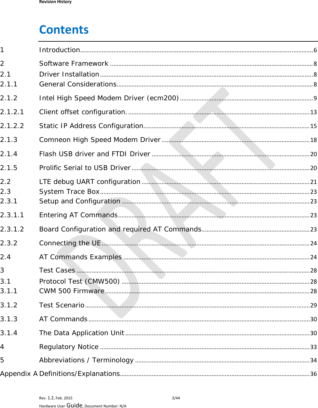
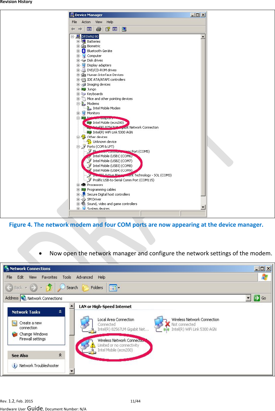
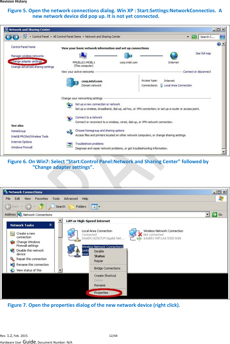
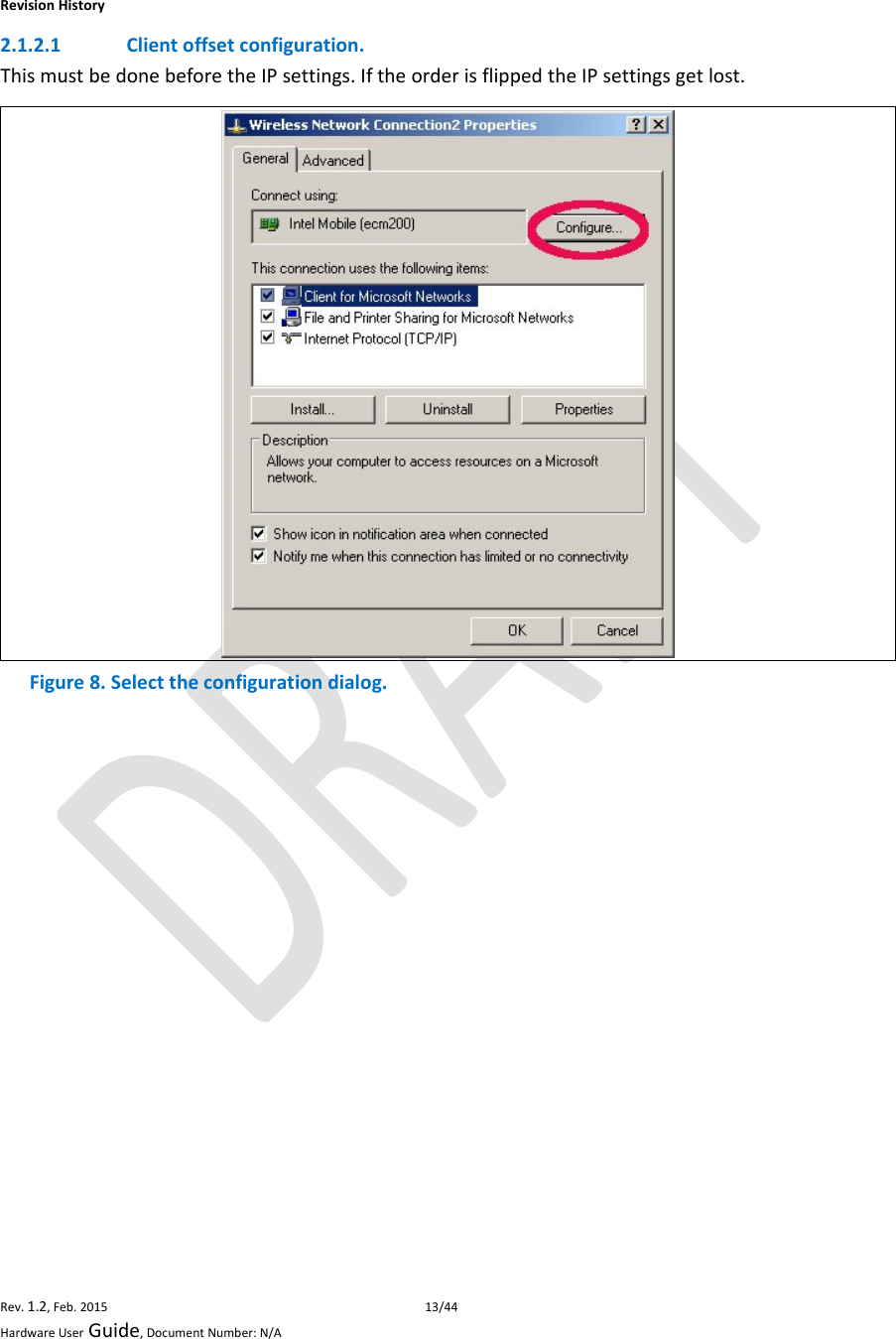
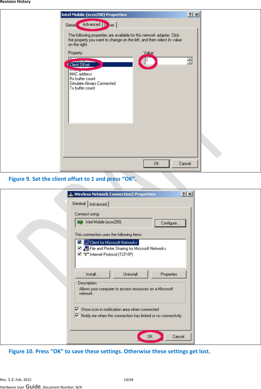
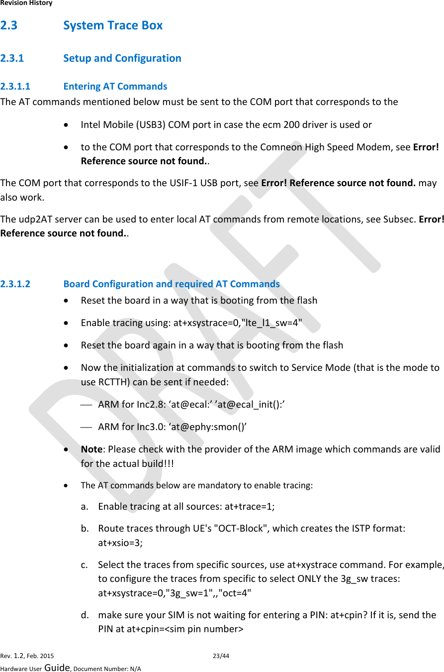
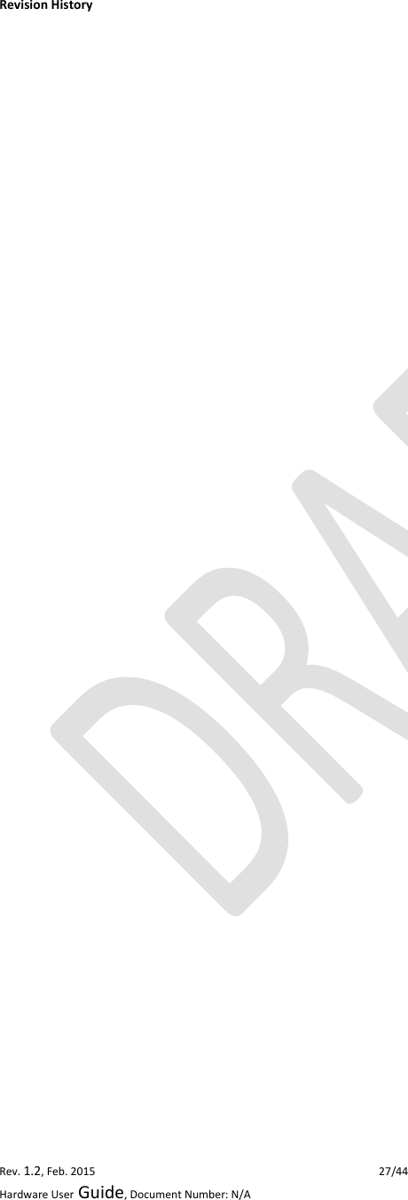
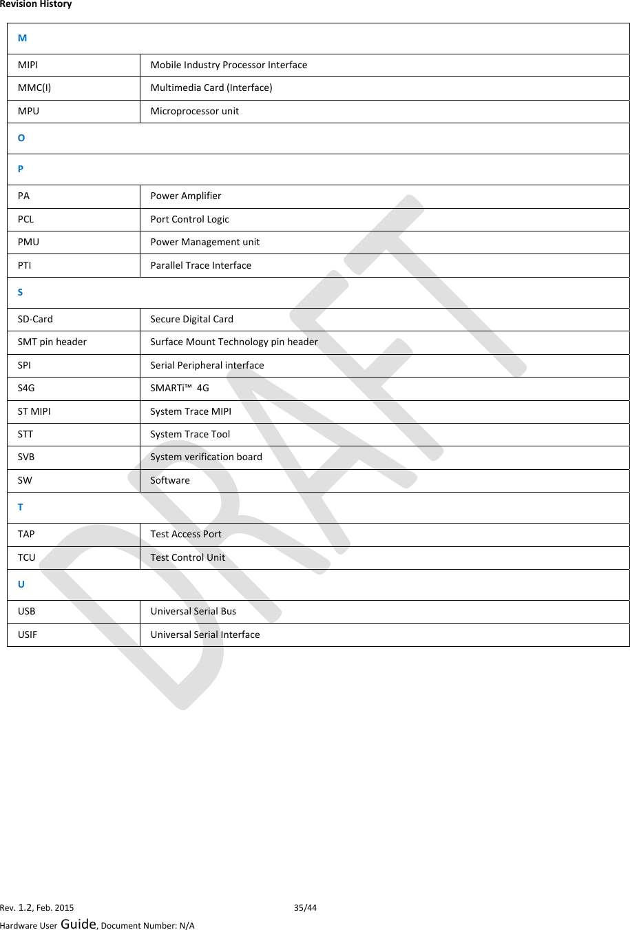
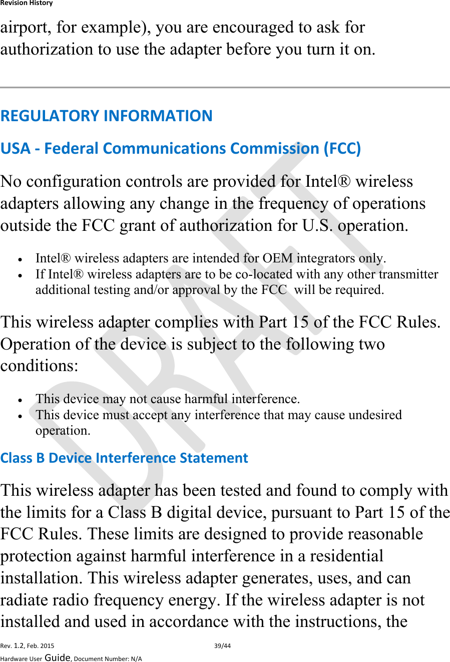
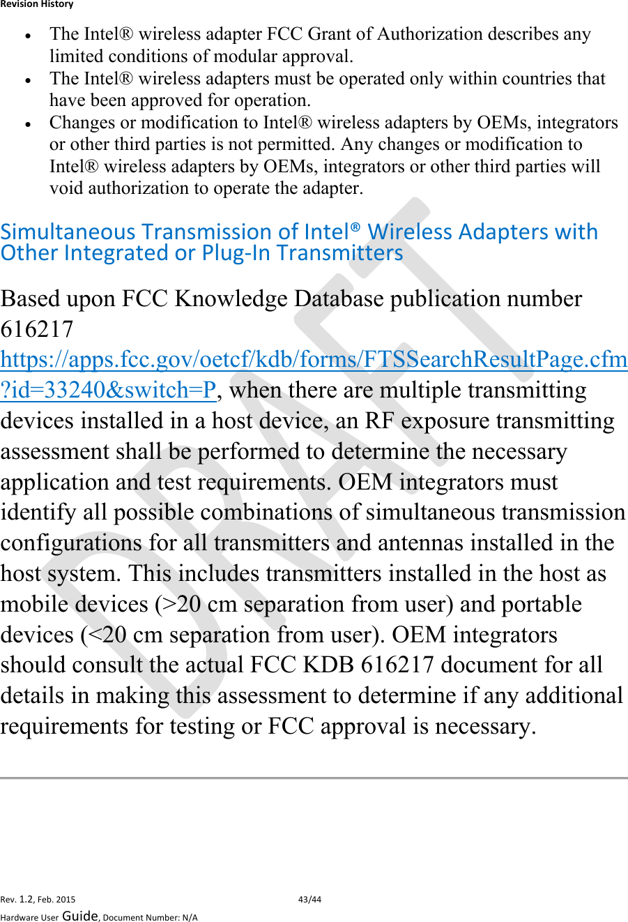
![RevisionHistoryRev.1.2,Feb.201526/44HardwareUserGuide,DocumentNumber:N/AOutgoingVoiceCallTable7.ATCommandsforanOutgoingCallCommandsentbyDTEDCEResponseDescriptionATOKAT+CLIP=1 ActivationofCallerlineIDpresentationOKATD+862161019000; OutgoingvoicecallOKVoicecallisacceptfromnetworkATH HangupOKSMSManagementTable8.ATCommandsforSMSManagementCommandsentbyDTEDCEResponseDescriptionAT+CMGF=1OKSetthetextmodeastheformatthatwillbeused.TobesetbeforeofthefirstoperationAT+CMGF=0OKSetthePDUmodeastheformatthatwillbeused.TobesetbeforeofthefirstoperationAT+CMGS=”0171112233”<CR>“Thisisthetext”<ctrl‐Z>CMGS:<mr>[,<scts>]ifPDUmode(+CMGF=0):+CMGS=<length><CR>PDUisCMGS:<mr>[,<ackpdu>]given<ctrl‐Z/ESC>OKorCMSERROR:<error>TestcommandAT+CMGS=?OK](https://usermanual.wiki/Intel/7262W2/User-Guide-2698346-Page-26.png)