Intelibs D01T4JX5 Radio Hub Unit (RHU) User Manual
Intelibs, Inc. Radio Hub Unit (RHU) Users Manual
UserManual.wiki
>
Intelibs
>
D01T4JX5 User Manual
Users Manual
Navigation menu
Upload a User Manual
Namespaces
Wiki Guide
HTML
PDF
Info
Views
User Manual
Discussion / Help
Navigation
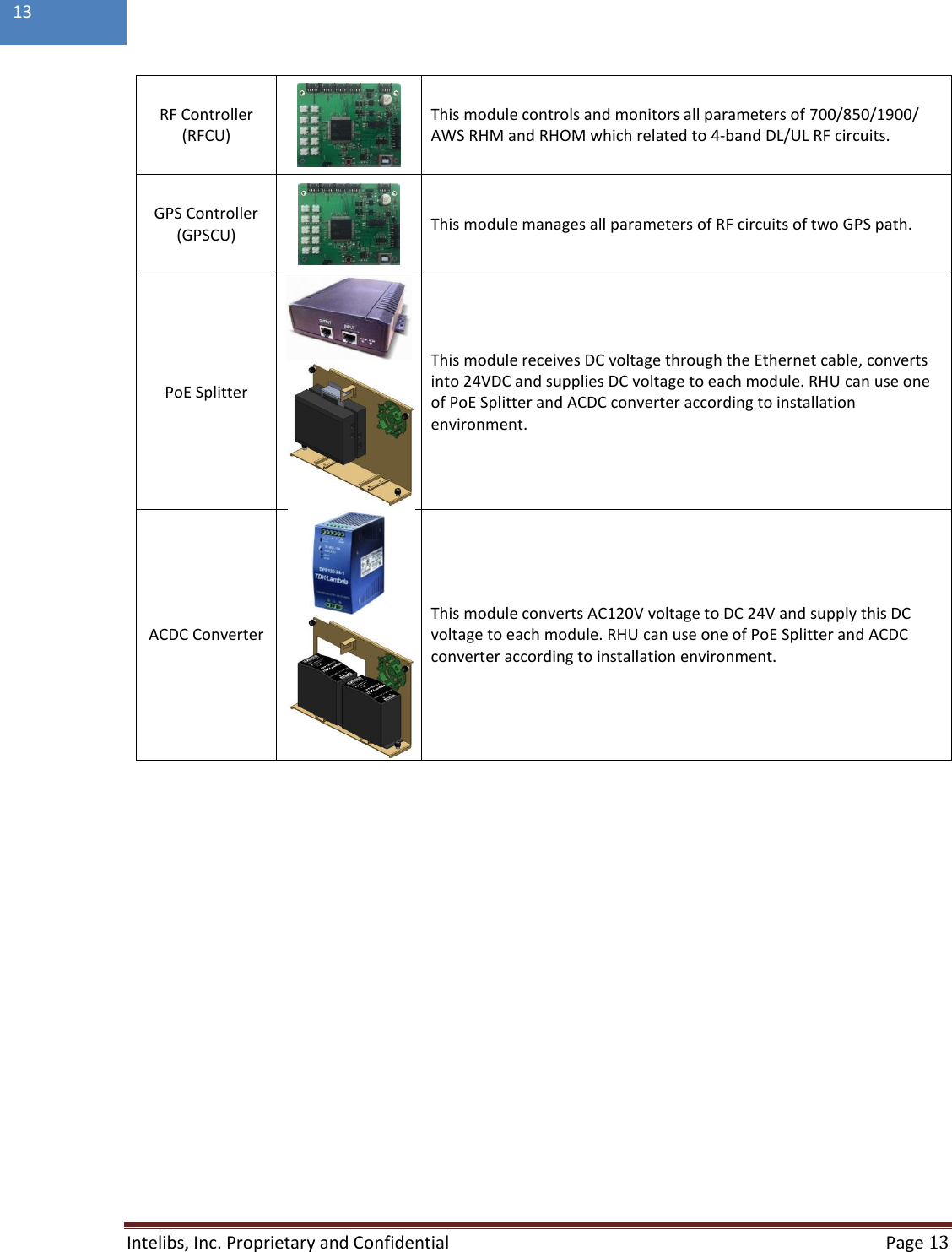
![Intelibs, Inc. Proprietary and Confidential Page 12 12 Table 2-3 RHU system’s modules Module Picture Description 700 RHM [Down Link] This module filters 700 DL RF signal from link antenna, amplifies with low noise, filters A/B/C/UpperC sub-band signals by digital band pass filters and transmits the selected 700 DL RF signal to optical module. [Up Link] This module filters 700 UL RF signal from optical module, filterers A/B/C/UpperC sub-band signals by digital band pass filters, amplifies to get high power and transmits 700 UL RF signal via antenna port. 850 RHM [Down Link] This module filters 850 DL RF signal coming from link antenna, amplifies with low noise, filters sub-band by digital band pass filters and transmits the selected 850 DL RF signal to optical module. [Up Link] This module filters 850 UL RF signal coming from optical module, filters sub-band by digital band pass filters, amplifies to get high power and transmits 850 UL RF signal to antenna. 1900 RHM [Down Link] This module filters 1900 DL RF signal coming from link antenna, amplifies with low noise, filters sub-band by digital band pass filters and transmits the selected 1900 DL RF signal to optical module. [Up Link] This module filters 1900 UL RF signal coming from optical module, filters sub-band by digital band pass filters, amplifies to get high power and transmits 1900 UL RF signal to antenna. 2100 RHM [Down Link] This module filters 2100MHz DL RF signal coming from link antenna, amplifies with low noise, filters sub-band by digital band pass filters and transmits the selected 2100MHz DL RF signal to optical module. [Up Link] This module filters 1700 UL RF signal coming from optical module, filters sub-band by digital band pass filters, amplifies to get high power and transmits 1700 UL RF signal to antenna. GPS FEM This unit filters GPS L1 band signal, amplifies by low noise, converts GPS signal into optical signal and transmits this optic signal to RU site via fiber. This unit has two GPS ports to support GPS redundancy function. If one GPS fails, second GPS port switch over automatically. RHOM [Down Link] This module combines 4-band mobile RF signal from 700/850/1900/ AWS RHM or GPS-FEM and converts into optical signal and transmits to RU site via fiber. [Up Link] This module converts optical signal coming from fiber into RF UL signals and amplifies UL signals to compensate fiber loss and transmits to 700/850/1900/AWS RHM or GPS-FEM.](https://usermanual.wiki/Intelibs/D01T4JX5/User-Guide-3245693-Page-12.png)
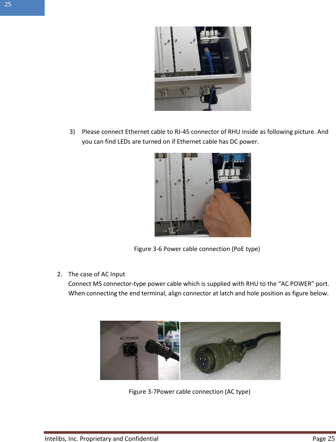
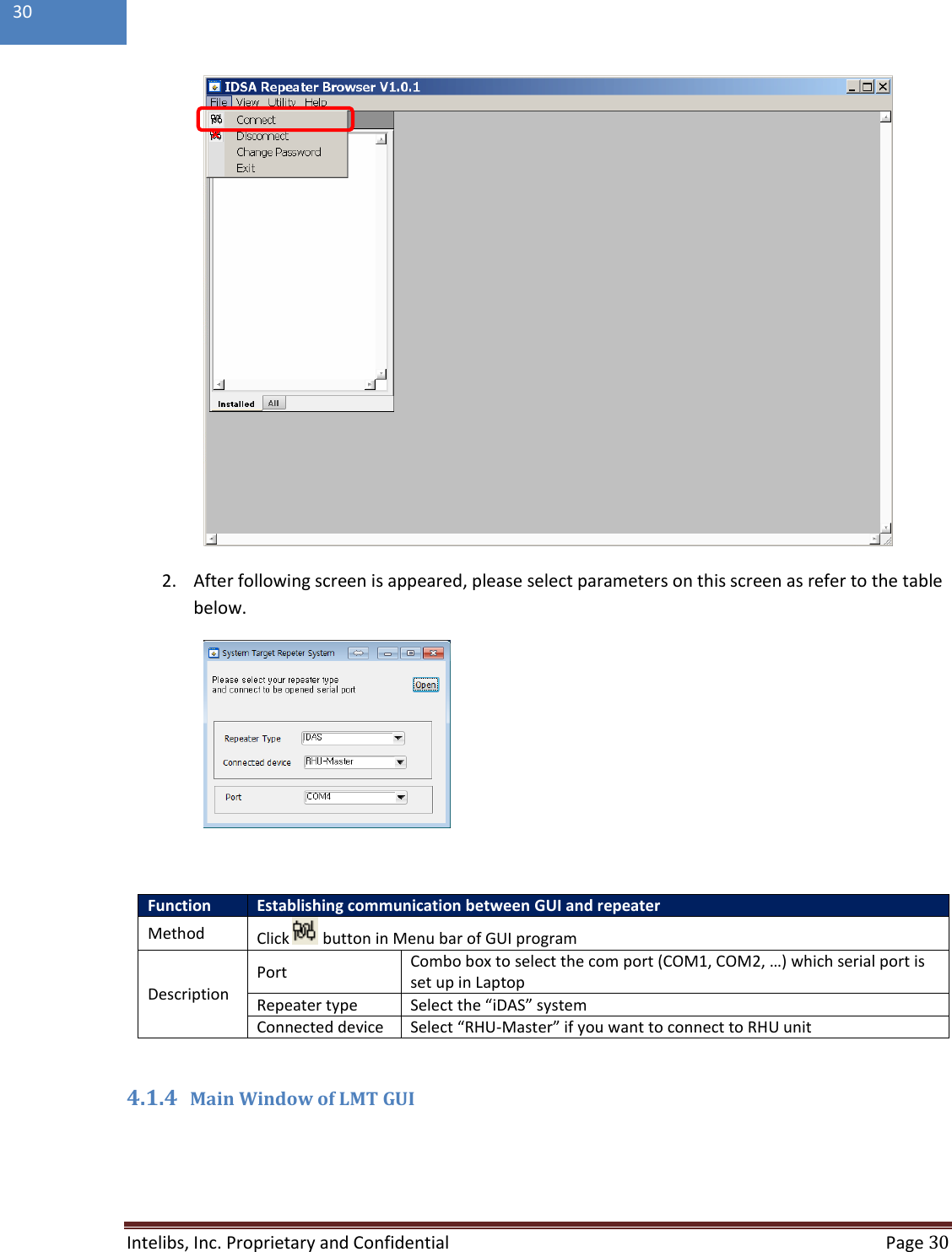
![Intelibs, Inc. Proprietary and Confidential Page 26 26 3.7 Optic cable RHU provides Six optic ports. Fiber_1 and Fiber_2 are the ports to connect with FHU/SRU/MRU, and Fiber_3 to Fiber_6 are the ports to connect with GPS BEUs. The type of fiber connector is all LC/UPC type connector as figure below. [LC/UPC type fiber connector] Figure 3-8 LC/UPC fiber connector connection Connect the fiber connector to the desired optic port in RHU. When connecting the optic connector, align the connector at latch and hole position, then plug in deeply to get the right connection.](https://usermanual.wiki/Intelibs/D01T4JX5/User-Guide-3245693-Page-26.png)
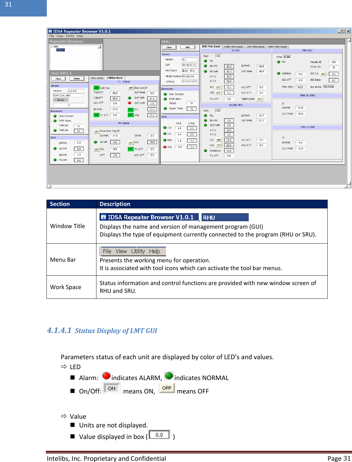
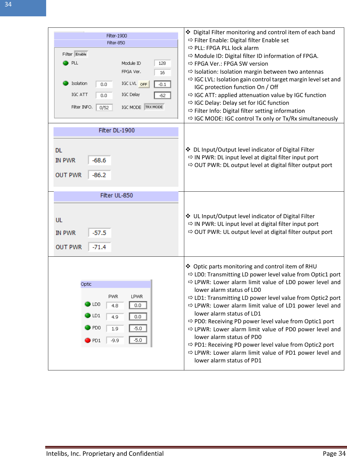
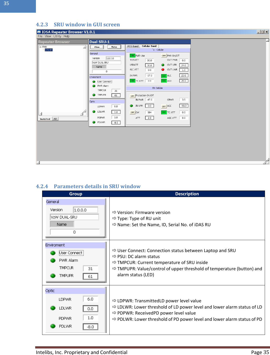
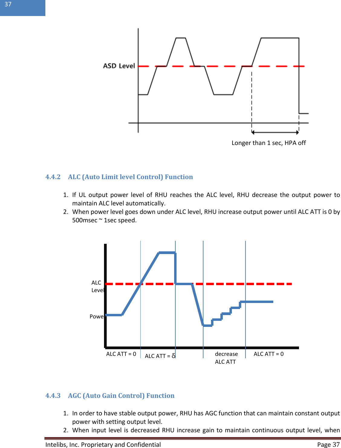
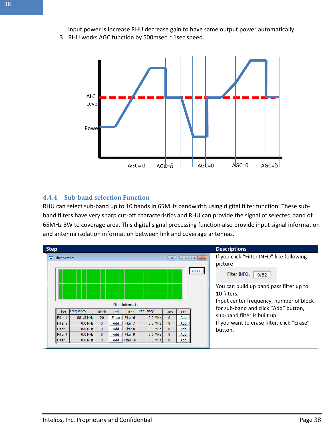
![Intelibs, Inc. Proprietary and Confidential Page 36 36 SRU parameter screen selection for PCS/Cellular band TAB. Path Use: Path use/not use selection TOTATT: Total attenuation value that is applied to DL path [TOTATT= USRATT + ALCATT + TCATT] USRATT: User attenuation set value for user gain set ALCATT: Attenuation value that controls DL gain automatically to maintain output level under ALC level when HPA output is higher than ALC level. INPWR: Input power level which input to SRU TCATT: Temperature compensation attenuation value and temperature compensation Function ON/OFF HPA On/Off: HPA ON/OFF function OUT PWR: Transmitting output power level from SRU antenna port OUT UPR: Output upper threshold level value and alarm OUT LWR: Output lower threshold level value and alarm ALC: Auto level limit control threshold value and on/off set ASD: Auto level shutdown threshold value and on/off set Protection On/Off: Protection Function ON/OFF to protect SRU from over input power IN UPR: UL(Rx) input upper threshold level value and alarm CW: CH number of pilot signal and ON/OFF function to check UL path gain budget (Pilot signal power level is -60dBm) IN PWR: RVS power value at the LNA output point ATT: User attenuation set value to control UL(Rx) gain OPWR: UL output power level of SRU AGC: Auto gain control level value and Function ON/OFF AGC ATT: Applied attenuation value by AGC function TC ATT: Applied temperature compensation attenuation value and function ON/OFF 4.3 Firmware download Firmware download is performed when system needs to be updated. Downloading improper images (executable file of repeater CPU) may cause harmful damages to equipment. 4.4 Additional function of RHU 4.4.1 ASD (Auto Shutdown) Function 1. If UL output power level of RHU is above the shutdown level longer than 1 second, RHU automatically turns off amplifier to protect undesirable transmission. 2. During shutdown state, monitor RU input power. If the level is below5dBfrom shut down level, turns on UL amplifier automatically.](https://usermanual.wiki/Intelibs/D01T4JX5/User-Guide-3245693-Page-36.png)