Intermec Technologies 07CN3 CN3 User Manual part 3
Intermec Technologies Corporation CN3 part 3
Contents
- 1. Compliance Insert
- 2. User Manual part 1 of 6
- 3. User Manual part 2 of 6
- 4. User Manual part 3 of 6
- 5. User Manual part 4 of 6
- 6. User Manual part 5 of 6
- 7. User Manual part 6 of 6
- 8. User Manual 1 of 6
- 9. User Manual 2 of 6
- 10. User Manual 3 of 6
- 11. User Manual 4 of 6
- 12. User Manual 5 of 6
- 13. User Manual 6 of 6
- 14. Manual
- 15. Radio Info
- 16. User Manual part 1
- 17. User Manual part 2
- 18. User Manual part 3
- 19. User Manual part 4
- 20. User Manual 1
User Manual part 3

6822 Series 80-Column Printer
User’s
Manual
Photo of printer not
available at this
time

6822 Series 80-Column Printer
User’s
Manual

6822 Series 80-Column Printer User’s Manual 97
6Troubleshooting
This chapter helps you correct printing problems that may
occur. If you experience a printing problem, you can perform
several tests to find and possibly correct the problem. In this
chapter you will find these sections:
•Checking the power source
•Aligning the printer mechanism
•Troubleshooting system components
•Communications pin-out configurations
Chapter 6 — Troubleshooting
98 6822 Series 80-Column Printer User’s Manual
Checking the Power Source
Press any button on the printer control panel. If there is power, the power
indicator (green LED) turns on and the printhead moves to its starting
position. If the printer emits beeps and any of the other indicators light
up or flash, observe the number of beeps and indicator flashes and see
“Printer Failure Indicators” on page 102
If there is no reaction from the printer after you press a key on the
control panel, or only the green power light blinks, verify that the power
cables are properly connected between the printer mechanism and its
power source (internal battery, vehicle cable, or ac). If none of these
steps “wake” up the printer with the problem, then you need to return the
printer for service.
•Internal battery
Check the battery and its cable by installing into another known-
good printer.
•Vehicle cable
Attach the printer in question to another vehicle power cable.
•AC power
Plug the printer into another outlet.
Aligning the Printer Mechanism
If head jams occur, you may need to align the printer mechanism.
To align the printer mechanism
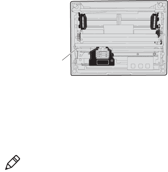
1Open the printer top cover, then install a ribbon cartridge (see
page 15) and position the printhead to the far left toward the green
thumb wheel.
Chapter 6 — Troubleshooting
6822 Series 80-Column Printer User’s Manual 99
2Check the area between the printhead and the printer cavity. If the
ribbon cartridge touches the pivot frame, the printer mechanism
needs realignment.
Printhead at far left in the printer
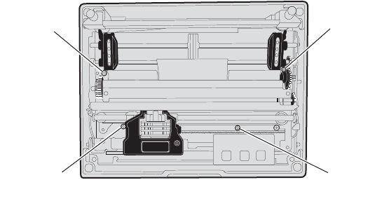
3Loosen the four screws that hold the mechanism in place using a
Phillips screwdriver (see the following illustration).
4Push the printer mechanism to the right away from the green thumb
wheel.
5Press on the right side of the printer mechanism to the back as far as
it will go.
Pivot frame
Note: In this position, the right back edge of the printer
mechanism may touch the pivot frame. The left side must not
touch the pivot frame.
Chapter 6 — Troubleshooting
100 6822 Series 80-Column Printer User’s Manual
6Hold the printer mechanism in place and tighten the screws in the
sequence shown below.
Four screws hold down the printer mechanism
Troubleshooting System Components
The printing system is composed of four basic components: printer,
computer, power source, and communications. Any one of these
components can prevent the printer from functioning properly.
Verifying the Printer Components
Power Source Verification
Start by verifying that power is available at the printer. Visually inspect
the control panel to verify that the power indicator (green LED) is lit. If
it is not, press the Set Page button and note if the power indicator lights
up. If it does, the power system is all right. If it does not, press the printer
reset button. If the power indicator still does not light, check the power
cable, by connecting it to a different printer. If the power indicator works
on the new printer, then the cable is all right, and the printer that was
originally connected is suspect. If it does not light, then the problem is
most likely the cable or the power source. Depending on the results,
either replace the cable or return the printer for service.
3 Top left
2 Bottom
left
1 Top right
4 Bottom
right
Chapter 6 — Troubleshooting
6822 Series 80-Column Printer User’s Manual 101
Printer Verification
If the power indicator works properly and the printer still does not print,
then printer errors are noted. If any indicators light when you press the
Set Page button, or the printer beeps, refer to the Printer Failure
Indicators table on page 102 to determine the problem.
If none of the listed conditions are indicated by the beep codes and
LEDs, yet the printer does not perform properly, then perform a printer
self-test. Press and hold (for several seconds) both Form Feed and the
Set Page buttons at the same time, until the printer beeps and all
indicator lights come on. The lights change throughout the test, as it
progresses.
At the end of the self-test, the printer generates a report. This report
verifies the following: errors detected during self-test, the error history,
and the communication configuration. If the printer self-test report does
not print, then reset the printer. If the report does print after resetting,
then the printer is all right and the reason the printer does not respond to
PC print requests is probably communications or PC related. If the report
is partially completed, and a printer error occurs during the printing of
self-test, refer to the Printer Failure Indicators table on page 102 for the
cause of the printer failure.
Perform a power-on-self-test (POST) to test for errors either by resetting
the printer or powering it up. If errors occur, audible error codes, along
with indicator light status, are produced during POST (see the POST
Error Codes table on page 104).
If the POST completes without error, try the printer self-test again. If the
self-test prints correctly, but the printer does not respond to the PC, then
the problem may be related to communications or PC problems.
Communications / PC Verification
Use the self-test report to verify that the communications protocol
options, selected at the printer, match those expected by the host. If they
do not match the expected results, reconfigure the printer using the
control panel configuration modes described below in the Configuration
part of this chapter.

Chapter 6 — Troubleshooting
102 6822 Series 80-Column Printer User’s Manual
If the protocol options match, then the communications cable may be
defective. To determine if the cable is working, substitute a new cable. If
the PC is suspect, substitute a different PC. A defective computer dock
might be another possibility.
Understanding Printer Errors
Printer Errors are divided into classes:
•Runtime errors
•POST errors,
•Fatal errors (consisting of flash write errors and EEPROM block
errors).
Runtime Errors
Runtime errors can occur during the course of printing. These errors are
displayed on the LEDs, along with beep sequences. This causes the
printer to stop printing and enter an error state. Then beep sequences are
emitted, LED codes are displayed, the error status may be sent to the
host (depending on the protocol), and the printer goes into suspend
mode.
The printer exits from the suspend mode when the user presses one of
the keyboard keys or communications is resumed from the host. The
printer also places the printhead in its home position and attempts to
recover from the error condition. Until the error condition is corrected,
the error procedure does not end, and the error state is not removed.
For paper out errors, load paper and press the Set Page button before
printing begins. Press the Form Feed button to load the paper to the top
of form. The following table provides a listing of printer failure
indicators and describes what they mean.
Printer Failure Indicators
Sets of Beeps Paper Out Head Jam Low Batt Meaning
1 beep Off Off On 12 V under voltage fault (Low Battery)
1 set of 2 beeps Off Off 2 blinks 12 V over voltage fault (Input Voltage
too high)
1 set of 3 beeps Off Off 3 blinks 24 V under voltage fault (internal
power supply failure)

Chapter 6 — Troubleshooting
6822 Series 80-Column Printer User’s Manual 103
Power-On-Self-Test (POST) Errors
When you reset the printer, a POST runs to determine why the printer
might be failing. Audible error codes, along with indicator light status,
are produced during POST if an error occurs. See on POST Error Codes
on page 104.
To perform a POST
1Open the printer case.
2Insert the printer diagnostic cable into the phone jack on the printer
and then connect the 9-pin D-Sub plug to your PC. The cable is used
during POST to configure the printer, access printer diagnostics,
update software, and install new fonts.
1 set of 4 beeps Off Off 4 blinks 24 V over voltage fault (internal power
supply failure)
1 set of 13 beeps Off Off Off Configuration error
2 sets of 2 beeps Off 2 blinks 2 blinks printhead over temperature
2 sets of 3 beeps On Off Off Paper Out
2 sets of 4 beeps Off On Off Head Jam
5 sets of 2 beeps 5 blinks 5 blinks 5 blinks Paper feed current fault
(Possible paper jam or feed motor
failure)
3 sets of 2 beeps 3 blinks Off 3 blinks printhead over current (printhead
failure)
3 sets of 4 beeps Off 3 blinks Off Home switch failure
4 sets of 2 beeps 4 blinks 4 blinks Off printhead short (printhead failure)
12 sets of 12 beeps Off Off Off Operating System software failure
Printer Failure Indicators (continued)
Sets of Beeps Paper Out Head Jam Low Batt Meaning
Note: The most common errors are Paper Out, Low Battery,
and Head Jam. Status indicators on the front panel alert you to
these errors. For a description see “Understanding the Status
Indicators” on page 3

Chapter 6 — Troubleshooting
104 6822 Series 80-Column Printer User’s Manual
3Press the Reset button to start the POST. When the POST starts,
green Power LED will come on followed by a single beep indicating
that the printer is active.
The printer emits beeps and flashes the LEDs to indicate the cause of any
POST errors. POST error codes are described in the following table.
Fatal Errors
There are two types of fatal errors, flash write errors and EEPROM
configuration block errors. These errors are extremely rare, but measures
are built into the printer diagnostics to track possible occurrences.
Flash Write Errors
Errors related to writing or erasing flash are critical errors. These errors
cause the printer to stop all processing and produce an LED code and a
sequence of beeps. The LED code indicates the address of the segment
where the error occurred in octal notation.
Note: After the test is completed, all LEDs turn off and the
printhead moves to the home position. Only runtime errors or
fatal errors are reported until the next time the printer is reset
and POST is performed.
POST Error Codes
Long
Beep
Short
Beep
Paper
Out
Head
Jam
Low
Batt Power Meaning
0 1 Off Off Off On Operational
00Off Off Off Off No Power
0 0 Off Off Off On Control program Initial Program Load (IPL)
successful
11Off On Off On Invalid CRC on boot block
1 2 Off On On On Invalid CRC on control program or program not
found
14Off Off Off On Upper 192K RAM failure
1 4 Off Off On On Upper 64K RAM failure
00On Off Off On Diagnostic mode command check
1 5 On Off On On Diagnostic flash memory check failed or is not
initialized
15On On Off On Diagnostic memory write failure
0 0 OnOnOnOnControl program IPL

Chapter 6 — Troubleshooting
6822 Series 80-Column Printer User’s Manual 105
The octal digit changes every four beeps until four octal digits are
output. Only four octal digits are output since blocks are 256 bytes in
size and flash can be addressed with a total of 0x7ff blocks. The segment
address output is the runtime address of the flash block and not the offset
of the block within flash.
To obtain the block offset within the flash
•Subtract 0x800 from the address output to determine the block offset.
The printer suspends after the processing the error code. When the
printer resumes, an error again and the printer suspends again. Reset the
printer to correct the error. If a reset does not correct the error, have the
printer checked by a qualified service technician.
EEPROM Configuration Block Errors
Errors related to an invalid configuration block (diagnostic block)
produce 13 beeps, and then the printer suspends. It continues to produce
this symptom until the configuration block error is corrected.
Configuration block errors may be caused by a flash write error or an
incorrect printer configuration. Reset the printer to correct the error. If a
reset does not correct the error, have the printer checked by a qualified
service technician.
Self-Test Function Descriptions
The self-test performs the following functions.
Boot Block Program Verification
A CRC (Cyclic Redundancy Check) is performed on the boot block
program. The calculated CRC is compared to the CRC embedded in the
program module.
Control Program Verification
A CRC is performed on the control program, which is loaded into
writable flash program memory. The calculated CRC is compared to the
CRC embedded in the program module. The results of this test are
printed on the self-test report.
Note: Flash write errors may be unrecoverable.

Chapter 6 — Troubleshooting
106 6822 Series 80-Column Printer User’s Manual
Font Module Verification
A CRC is performed on the font modules, which are loaded into writable
flash font memory. The calculated CRC is compared to the CRC
embedded in the program module. Results are printed on the self-test
report.
A2D Check
Current reading of the A2D sources are performed, and the results are
printed on the self-test report.
Nonvolatile Diagnostic Memory Verification
A CRC is performed on the area of the nonvolatile diagnostic memory
that has a CRC over it. Results are printed on the self-test report.
Nonvolatile Diagnostic Memory Update
The nonvolatile diagnostic memory is updated from the nonvolatile
diagnostic memory data shadowed in memory.
Detailed Printer Self-Test
Perform a self-test to verify printer functions, and provide reporting of
printer diagnostics. The self-test performs a series of internal diagnostics
and prints the results. When the self-test begins, the beeper sounds for
half a second and all LEDs turn on for half a second.
Initiating Self-Test
•While the printer is idle or in Suspend mode, press the Line Feed and
Set Page buttons simultaneously to initiate a
self-test.
Terminating Self-Test
•Press the Line Feed and Set Page buttons simultaneously to manually
terminate a self-test.
Self-Test Report
Note: This method is recommended to determine printer
functionality.
Chapter 6 — Troubleshooting
6822 Series 80-Column Printer User’s Manual 107
A self-test is equivalent to a warm start. Both are performed when you
simultaneously press Form Feed and Set Page buttons on the control
panel for a few seconds. Release the buttons when the printer beeps and
all indicators are lit. If you press the buttons for too long, the self-test
will not happen and the printer will form-feed one page.
As the self-test progresses, the indicator lights change. Internal tests are
performed and the two page report is printed. This report provides
helpful information in diagnosing and troubleshooting printer problems.
When you perform a self-test, the following actions occur:
•All LEDs are turned on to verify the lights work
•A 600 ms beep is emitted to verify the beeper works
•LEDs flash individually to show progress during internal tests
•Current voltage and ambient temperature are obtained
•Validity of diagnostic block program is checked
•Validity of boot block program is checked
•Validity of control program is checked
•Validity of loaded fonts is checked
•LEDs turn off
•Self-test report is printed
Printer capability is diagnosed by printing the report. Device errors are
displayed on the LEDs and emitted by the beeper. The printer then does
a warm reset (soft reboot) when an error is encountered or when the self-
test report prints.
Understanding the Self-Test Report
The self-test report is divided into sections. Refer to page 110 and
page 111 for a sample printout. All other values are informational only.
Remember that these values are cleared after the self-test.
• The printer model number is given on line 1 (first line). This identifies
the printer type used, in this case the 6822.
• The 8-digit serial number of the printer is listed on line 4 under the
“Serial#” heading on line 3. The serial number is also on the inside of
the printer. In portable printers, raise the printer mechanism to look for
the number on the inside back wall.

Chapter 6 — Troubleshooting
108 6822 Series 80-Column Printer User’s Manual
•Battery Voltage, (line 13)
Indicates the input voltage sampled at the beginning of the self-test.
The input range must be between 7.5 and 15 V. The input voltage
must be greater than 10.5 V to charge the internal battery. At 7.5 V or
less, the Low Batt LED comes on and the printer enters Sleep mode.
At 10.5 V or less, the Low Batt comes on but the printer still prints.
•Auto Feed (line 16)
Auto feed is a configurable item. Carriage Return (CR) means no
auto linefeed. This is the most common setting for applications using
NPCP CR+LF means a line feed will be added to each CR. This
setting can produce double-spacing of reports. See “Setting the
Autofeed” on page 29
•Interface Mode (line 17)
Interface mode lists the interface protocol for the printer. The typical
setting is NPCP. Others include DTR with no, odd, or even parity,
and IrDA. See “Protocol Selection Mode” on page 29
•Bit Rate (line 18)
Bit rate is commonly set to 19200 (19.2K) or 9600 bps. See
“Selecting the Bit Rate” on page 29
•A2D History (lines 21 through 25)
Shows the recorded history for voltage measurements and
temperature measurements.
•Head Jam History (lines 26 through 29)
Provides information on head jams. If the printer is having frequent
head jams, these lines can assist in determining the problem.
Head Jam History Information
Heading Description
Home Err indicates the home position LED sensor has failed.
Command Indicates which printer command was executed when the
head jammed.
Direction Indicates which way the head was moving, left is toward the
home position and right is away from the home position.
Home position is at the extreme left, toward the green thumb
wheel.
Speed Indicates the acceleration speed of the printhead when the
jam occurred.

Chapter 6 — Troubleshooting
6822 Series 80-Column Printer User’s Manual 109
•Head Dot Pattern (line 37)
Is used to verify the individual dot wires. There should be nine dots.
If some dots are missing, it could be a printhead failure or a circuit
board failure.
•Error Log information appears on lines 38-43. This information is
cleared after every self-test.
Step The acceleration step at the jam. 0 means no steps were
taken, 15 means all steps were taken. 1-14 indicates the
printer jammed during acceleration or deceleration.
Temp The ambient temperature at the last head jam. The
temperature is listed in Celsius.
Position Position of carriage at the time of the jam in 1/720 in = 12 *
step position. Divide the number by 12 to get the step
position. There are 512 steps across the page. If it is jammed
at position 0, check the printer mechanism alignment. If it is
jamming in the middle, it is more likely a dirty ribbon or
obstruction in the printhead’s path.
Head Jam History Information (continued)
Heading Description
Error Log Information
Heading Description
PE Number of paper jams while feeding paper
HJ Number of head jams while printhead is moving
12Vu Number of 12 V under-voltage
12Vo Number of 12 V over-voltage
24Vu Number of 24 V under-voltage (head/motor voltage)
24Vo Number of 24 V over-voltage
Home Number of home detect errors (typically caused by paper
scraps or circuit failures)
Temp Unused
OverC Number of head over-current errors (typically caused by a
bad printhead)
HeadS Number of head driver short errors (typically caused by
circuit failures)
Fault Number of paper feed motor over current errors (excess
current in paper feed motor could indicate circuit failure)

Chapter 6 — Troubleshooting
110 6822 Series 80-Column Printer User’s Manual
Sample First Page of the Self-Test
----------------------------------------------------------------------------------------------
------------------------------------------- 1NP6822
2 Copyright 1997, 1998, Intermec Technologies Corporation. All Rights Reserved.
3Serial# MFG Date Hardware Check Repairs Svc Date
412345678 yy/mm/dd ddd-ddd-ddd/dddd (TOP) GO/NG 00 yy/mm/dd
5 ddd-ddd-ddd/dddd (MLB)
6 ddd-ddd-ddd/dddd (PS)
7 ddd-ddd-ddd/dddd (IOB)
8Revisions:..........0000000000303100
9Bootblock: NPBB6822.MOD - Version XX.XX XXXX XXXX GO/NG
10Control Program: npfl6822.mod - Version XX.XX XXXX XXXX GO/NG
11Font Module: nftxxxxx.mod - Version XX.XX XXXX XXXX GO/NG
12Font Module: nftxxxxx.mod - Version XX.XX XXXX XXXX GO/NG
13Battery Voltage: 012.34 Low...../....High
14Total Pages: 123456
15Zero Font Style: O
16Auto Feed: CR
17Interface mode: NPCP
18Bit Rate: 19200
19Cold Starts: 00024
20Warm Starts: 00050
21A2D History
22 Curr Low High Min Max Error Page Count
2324v: 024.00 023.21 023.91 023.21 024.51 027.21 00401 00021
2412v: 012.55 010.91 013.51 010.90 014.50 8.71 00401 00021
25Temp: 023 -020 055 -021 060 000 00401 00021
26Head Jam History
27Total Head Jams: 00186
28Home Command Direction Speed Step Temp Position Page
29 Print Left Const 010 -010 01440 12345
30NPCP History
31Disc Addr Parity IFTS Seq CRC Frame Bind IPLDU
3212345 12345 12345 12345 12345 12345 12345 12345 12345
33IRDA History
34 FramesOk BroadCasts CRC/TMO DISCARD
35rx 1234567890 1234567890 0123456789 0000000000
36tx 1234567890 1234567890 0123456789 0000000000
37HEAD DOT PATTERN
38 Error Log
39PE HJ 12Vu 12Vo 24Vu 24Vo Home Temp OverC HeadS Fault ADErr EEErr
40Dlink Llink
4112345 12345 12345 12345 12345 12345 12345 12345 12345 12345 12345 12345 12345
4212345 12345 12345 12345 12345 12345 12345 12345 12345 12345 12345 12345 12345
4312345 12345 12345 12345 12345 12345 12345 12345 12345 12345
ADErr Number of A2D conversion failures
EEErr Number of EEPROM write failures to diagnostic block
Dlink Number of software memory errors (corruption in internal
memory)
Llink Number of software memory errors
Error Log Information (continued)
Heading Description
Note: Lines 15-18 are factory default printer settings. Take note
of these lines when reading the self-test report.

Chapter 6 — Troubleshooting
6822 Series 80-Column Printer User’s Manual 111
Sample Second Page of the Self-Test
Page 2 of the self-test contains the print pattern used to diagnose printer
mechanical behavior. The pattern continuously prints the ASCII
characters between 33 and 126 decimal inclusive for the entire page, or
until you cancel the print by pressing a button on the printer. An example
of that rotating pattern is shown below.
!”#$%’()*+,–./
0123456789:;<=>?@ABCDEFGHIJKLMNOPQRSTUVWXYZ[\]^_’abcdefghijklmnopqrstuvwxyz{|}~!”#$%’
()*+,–./
0123456789:;<=>?@ABCDEFGHIJKLMNOPQRSTUVWXYZ[\]^_’abcdefghijklmnopqrstuvwxyz{|}~!”#$%’
()*+,–./
0123456789:;<=>?@ABCDEFGHIJKLMNOPQRSTUVWXYZ[\]^_’abcdefghijklmnopqrstuvwxyz{|}~!”#$%’
()*+,–./
0123456789:;<=>?@ABCDEFGHIJKL
Self-Test Failure
•For help, see “Miscellaneous Troubleshooting Tips” on page 111.
•Check the power source (internal battery, charge cable, or ac adaptor)
for a possible power failure.
Miscellaneous Troubleshooting Tips
The following table lists actual printing problems, possible causes, and
actions you should take to correct a problem.
Possible Printer Problems
Symptom Test or Cause Solution
Printer does not communicate
with the mobile computer.
Bluetooth unable to connect.
Incorrect protocol selection. Check lines 17 and 18 on the self-test
report for correct bit rate and protocol
selection. Change protocol settings
through configuration process.
Make sure you are in range
(10 cm to 10 m) Make sure your device is
configured to be discoverable
and/or connectable. For help,
see “Bluetooth Configuration
Commands and
Specifications” on page 133.
Make sure the Bluetooth shutdown
timer has not expired
Double-spacing on
application reports but single-
spacing on
self-test.
Check line 16 on the self-test
report. CR+LF indicates an
incorrect configuration for
NPCP.
For help, see “Cleaning the Mask
Spring” on page 22.
Zero prints incorrectly (with
or without slash). Check line 15 on the self–test
report for the Zero Font Style
setting.
If incorrect, adjust the zero print
option, see “Cleaning the Mask
Spring” on page 22

Chapter 6 — Troubleshooting
112 6822 Series 80-Column Printer User’s Manual
Does not print extended
character set — missing font. Check line 11 or 12 on the
self–test report to see if the
NFT0000.MOD file is listed
after Font Module.
Use the 6820 Printer Tool Kit to reload
the font file or send the printer in for
hardware repair.
Printer emits 1 or 2 beeps or
blinking green light is the
only indicator.
Printer mechanism does not
have adequate power for
printing. The 12 V may be
under or over voltage fault.
(Note: Error lights do not
flash if voltage is too high)
Check battery or power supply.
If battery, recharge or replace
(see “Installing the Internal
Battery” on page 10
If power supply, adjust supply
voltage to 7.5 to 15 V. Check the printer’s internal battery, if
installed. Check the vehicle charge
cable (see 6822 Printer Installation
Instructions P/N 931-052-001).
Printer emits 2 sets of 3 beeps Printer out of paper Reload paper into printer mechanism.
For help, see “Loading the Paper Tray”
on page 13.
Printer works but some or all
LEDs do not work. Gray ribbon cable connecting
control panel board to pivot
frame assembly is loose.
Call Customer Support
(800-755-5505) or send printer for
hardware repair.
Printer does not print No voltage Voltage too high or low. Check line 13
on the self–test report, under the
Battery Voltage heading
No data input Adjust supply voltage to
7.5-15 V
Tighten computer
connections.
No paper feed (paper jam or head jam)
Te s t: Pull paper toward roller.
Cause: If paper is resistant: Paper tray too full Torn paper perforation
Paper wrinkled, creased,
moist, or perforations missing White ribbon cables
obstructing paper Head Jams due to carriage alignment.
Check line 29 on self-test report, under
Position heading, for value.
Ensure fewer than 200 3-ply
sheets in the deep paper tray
and fewer than 50 3-ply
sheets in the shallow paper
tray.
Remove torn paper, load and center
new paper, readjust pinfeed holders.
Possible Printer Problems (continued)
Symptom Test or Cause Solution

Chapter 6 — Troubleshooting
6822 Series 80-Column Printer User’s Manual 113
Replace the paper. Straighten the white ribbon
cables. If “0,” realign mechanism in pivot tray.
See “Aligning the Printer
Mechanism” on page 98
No paper feed (paper jam or
head jam) Move the printhead manually
from side to side. Remove ribbon cartridge, move
printhead. If smooth, ribbon is
jammed.
Remove ribbon cartridge, move
printhead. If still resistant, mask spring
is bent or damaged.
Cause: printhead gap
adjuster too tight.
Cause: Paper scraps found in
printer mechanism or around
platen.
Printer mechanism unlatched
(unlocked). (portable, fixed
mount printers)
Remove ribbon cartridge and
turn knob. If ribbon resists,
replace ribbon cartridge (see
“Installing the Ribbon
Cartridge” on page 11
Replace the mask spring see
“Cleaning the Mask
Spring” on page 22
Set the head gap adjuster to
the fifth notch away from the
paper see “Adjusting the
Printhead Gap” on page 12
If ribbon cartridge bumps
against inside of printer,
check white ribbon cable,
home position sensor, and
four screws.
Remove any paper scraps, do
a cleaning.
Latch (lock) the printer
mechanism into place.
Perform a self-test.
Possible Printer Problems (continued)
Symptom Test or Cause Solution
Note: In paper jams or head jams, press the Set Page button to
clear the printer before printing can resume.

Chapter 6 — Troubleshooting
114 6822 Series 80-Column Printer User’s Manual
Compatibility Issues
Use the following information to determine some compatibility issues
that come up relative to the 6822:I
Understanding Diagnostic Information
Diagnostic information is stored in flash to support the hardware
configuration, both at time of manufacture and in the field. This includes
recording the initial configuration changes to hardware and software,
and various environmental statistics helpful in determining why failures
are occurring in the field. The flash is provided for storage of critical
data that must remain in the unit after power to the unit is lost. The data
in the flash is used for diagnostic information for a catastrophic failure,
or over the phone with a customer.
Diagnostic information is updated and maintained by the printer. All
diagnostic information is shadowed in RAM. At the end of every 50
forms, the flash information is updated from the RAM. The printer also
updates the diagnostic information for nonrecoverable error, printer
resets, printer self-test, and remote polling of diagnostic information.
Fields are stored with ID first, then length, then data. The details of the
data and the length of the entire field, including ID and Length bytes, are
shown in the “Diagnostic Information” table on page 115.
The amount of flash memory reserved for nonvolatile diagnostic
memory is 16 K bytes. Printer self-test prints most of the information
contained in the diagnostic memory for remote and end-user diagnostic
access.
Compatibility Issues and Conclusions
Issue Conclusion
Does a 6820 ribbon work on the 6822? Yes.
Do 6820 applications work on the 6822? Yes. Applications that work on the 6820 also work on
the 6822.
Does the 6822 work with an application
that downloads some custom characters to
the printer?
Yes. The downloadable character set feature is the same
for both the 6820 and 6822.
Can 6820 printers be replaced with 6822s? Yes. 6822s can be installed on existing 6820 mounting
brackets.

Chapter 6 — Troubleshooting
6822 Series 80-Column Printer User’s Manual 115
Diagnostic Information
Field
Id Length Description Stored as
Tota l
Length
01 4 Serial Number 7 digit BCD set at MFG 39 bytes
3Date of Manufacture, yy/mm/dd 6 digit BCD set at MFG
7
7
7
7
Hardware Configuration
ddd-ddd-ddd/ddd (top level P/N)
ddd-ddd-ddd/ddd (control board)
ddd-ddd-ddd/ddd (power supply)
ddd-ddd-ddd/ddd (I/O board)
52 digit BCD set at
MFG
2CRC of preceding fields 2 byte binary set at MFG
08 8 Hardware Revisions: ECNs. applied. 64
ECNs can record separately by number 1-64. 8 byte bit field 11 bytes
1Service Repairs: a two-digit field indicating
number of times serviced 2 BCD digits
3 Date of last repair, yy/mm/dd 6 BCD digits
09 2 Cold starts since MFG or last repair binary digits 8 bytes
2 Warm starts since last cold start binary digits
2Pages printed over life binary digits
10 2 Last high and low voltage extremes on 24 V
input over last 50 reports. Extremes stored as
8-bit A2D conversions
2 bytes 11 bytes
2Voltage extreme history stores min/max 24 V
A2D conversions over printer life 2 bytes
1 24 V voltage error. Voltages greater than 10%
considered errors. A2D error count 1 byte
2Form number at last voltage error 2 bytes
2 24 V error count 2 bytes
20 2 Last high and low voltage extremes on 12 V
input over last 50 reports. Extremes stored as
8-bit A2D conversions
2 bytes 11 bytes
2 Voltage extreme stores min/max 12 V A2D
conversions over printer life 2 bytes
112 V error. Voltages less than 10.5 V and
greater than 14.5 V are considered errors.
A2D value is recorded
1 byte
2 Page number at last 12 V error 2 bytes
212 V error count 2 bytes
30 2 Temperature, maximum and minimum over
last 50 reports. Set A2D value 2 bytes 11 bytes

Chapter 6 — Troubleshooting
116 6822 Series 80-Column Printer User’s Manual
2Temperature, min/max over printer life. Set
A2D value 2 bytes
1 Temperature error. Last A2D conversion
below -10 or above 60°C recorded 1 byte
2Page number at last temperature error 2 bytes
2 Total number of temperature errors 2 bytes
40 2 Total number of head jams 2 bytes binary 11 bytes
1 Command
0 = Stop
2 = Print
4 = Print/LF
6 = Seek
8 = Slow Seek
10 = Change Speed
12 = Feed
14 = Wait
Speed
00 = Init
01 = Low
10 = High
Direction
1 = Left
0 = Right
Home Switch
0 = No Error
1 = High Error
bits 0-3
bits 4-5
bit 6
bit 7
1Acceleration or deceleration stop motor value
when jam occurred 1 byte binary
1 Ambient temperature when had jam
occurred. Set A2D value 1 byte
2Form number where head jam occurred 2 bytes binary
2 Carriage position where head jam occurred 2 bytes binary in 1/720
in
60 4 IrDA rxFramesOK – total frames received
OK 4 bytes 46 bytes
Diagnostic Information (continued)
Field
Id Length Description Stored as
Tota l
Length

Chapter 6 — Troubleshooting
6822 Series 80-Column Printer User’s Manual 117
4 IrDA rxFrameCrcErr – total frames received
with CRC error 4 bytes
4IrDA rxTotalBytes – total bytes received OK 4 bytes
4 IrDA rxFramesDiscardBuf – total frames
discarded due to no buffer space 4 bytes
4IrDA rxBroadcastFrames – total broadcast
frames received OK 4 bytes
4 IrDA rxFramesDiscardHwErr – total
received frames discarded due to hardware
error
4 bytes
4IrDA txFramesOK – total frames transmitted
OK 4 bytes
4 IrDA txTotalBytes – total bytes transmitted
OK 4 bytes
4IrDA txBroadcastFrames – total broadcast
frames transmitted OK 4 bytes
4 IrDA txFramesNotTxTimeout – total frames
not transmitted due to time out 4 bytes
4IrDA txFramesNotTxHwErr – total frames
not transmitted due to a hardware error 4 bytes
70 2 Paper out count 2 bytes 74 bytes
2Head jam count 2 bytes
2 12 V low count 2 bytes
212 V high count 2 bytes
2 24 V low count 2 bytes
224 V high count 2 bytes
2 Home switch error count 2 bytes
2Unused 2 bytes
2 Over current error count 2 bytes
2Head short error count 2 bytes
2 Paper fault error count 2 bytes
2A2D conv. error count 2 bytes
2 EEPROM write error count 2 bytes
2Double link error count 2 bytes
2 Lost link error count 2 bytes
Diagnostic Information (continued)
Field
Id Length Description Stored as
Tota l
Length

Chapter 6 — Troubleshooting
118 6822 Series 80-Column Printer User’s Manual
2Out of buffers error count 2 bytes
2 Unused 20 * 2 bytes
Diagnostic Information (continued)
Field
Id Length Description Stored as
Tota l
Length
Chapter 6 — Troubleshooting
6822 Series 80-Column Printer User’s Manual 119
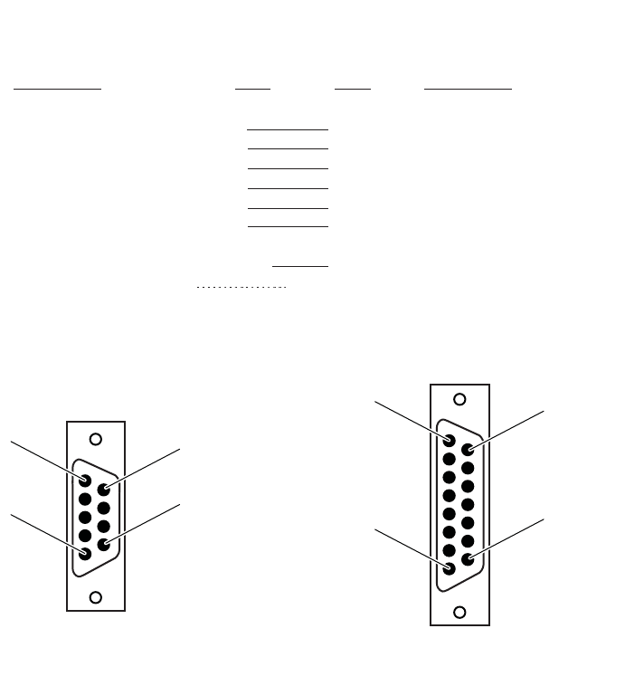
Communications Pin-Out Configurations
This section shows common cable configurations between a mobile
computer or a dock and the printer.
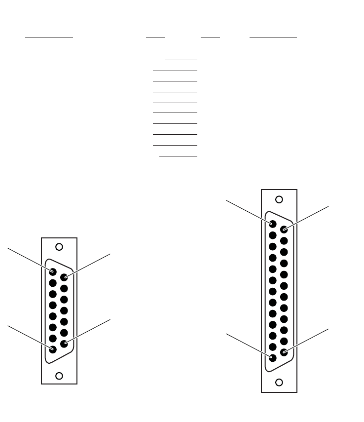
15-Pin to 25-Pin Cable (P/N 216-605-1XX)
Mobile Computer
Signal Name
Chassis Ground
Charge Input
SG (Signal Ground)
DSR (Data Set Ready)
DTR (Data Terminal Ready)
CTS (Clear To Send)
RTS (Ready To Send)
RXD (Receive Data)
TXD (Transmit Data)
Dock_A/B_SW
Wall Mount Printer or
Remote Mount Terminal Holder
15-Pin DSUB Male
15-Pin to 25-Pin Cable (P/N 216-605-1XX)
25-Pin DSUB Male
Signal Name
NC (No Connection)
HHC_CHARGE
GND
DTR
NC
RTS
CTS
TXD
RXD
Term A/B
Pin #
shell
8
9
7
2
6
3
5
4
NC
Pin #
1
9
7
6
20
5
4
3
2
12
shield
8
1
15
9
13
1
25
14
Chapter 6 — Troubleshooting
120 6822 Series 80-Column Printer User’s Manual
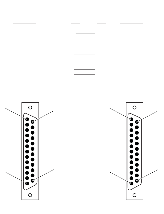
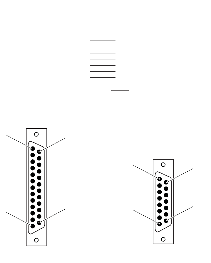
25-Pin to 25-Pin Cable (P/N 216-771-XXX)
PC
* Signals are not available on the 6100 Dock
Signal Name
DTR (Data Terminal Ready)*
RC (Receive Carrier)
TC (Transmit Carrier)
DCD (Data Carrier Detect)
SG (Signal Ground)
DSR (Data Set Ready)*
CTS (Clear to Send)
RTS (Ready to Send)
RXD (Receive Data)
TXD (Transmit Data)
Wall Mount Printer
25-Pin DSUB Female
25-Pin to 25-Pin Cable (P/N 216-771-XXX)
25-Pin DSUB Male
Signal Name
NC (No Connection)
NC
NC
NC
GND
DTR
RTS
CTS
TXD
RXD
Pin #
20
17
15
8
7
6
5
4
3
2
Pin #
20
17
15
8
7
6
5
4
3
2
13
1
25
14
13
1
25
14
Chapter 6 — Troubleshooting
6822 Series 80-Column Printer User’s Manual 121
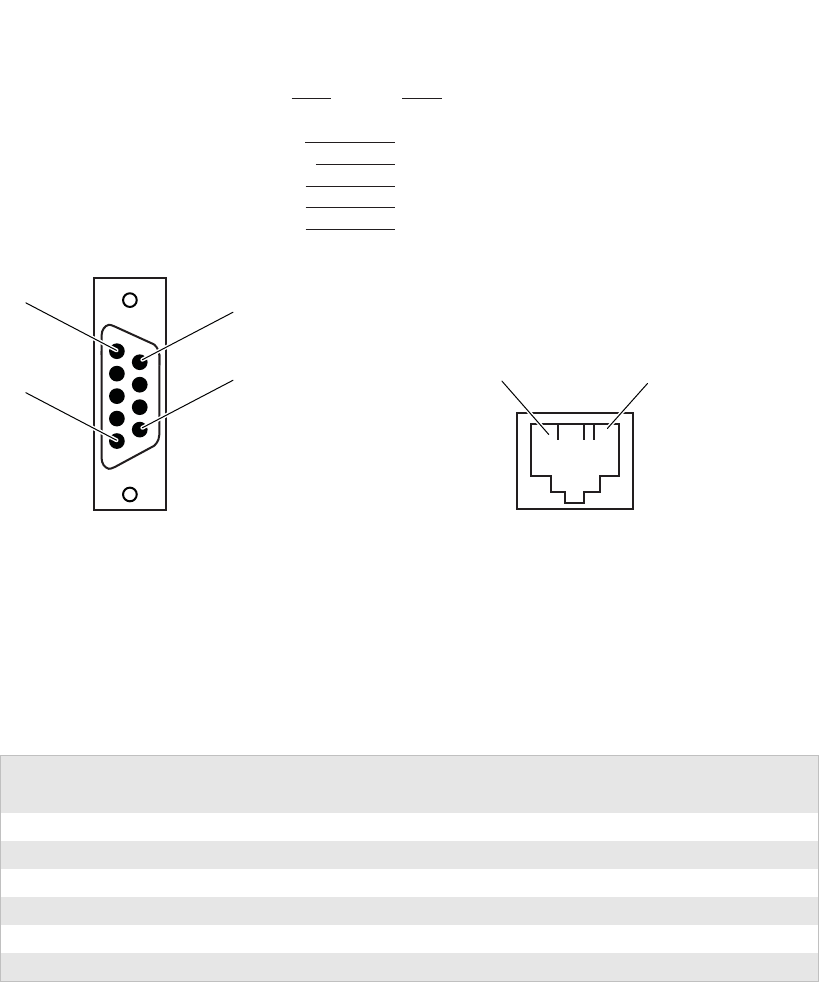
9-Pin to 15-Pin Cable (P/N 226-016-XXX)
PC
Signal Name
TXD (Transmit Data)
RXD (Receive Data)
RTS (Ready to Send)
CTS (Clear to Send)
DSR (Data Set Ready)
SG (Signal Ground)
Chassis Ground
Printer
9-Pin DSUB Female
9-Pin to 15-Pin Cable (P/N 226-016-XXX)
15-Pin DSUB Female
Signal Name
RCT
TXD
CTS
RTS
DTR (Data Terminal Ready)
GND
Chassis Ground
Terminal Charge out to computer
Pin #
3
2
7
8
6
5
shell
Pin #
4
5
3
6
7
9
shell
8
1
5
6
9
shield
1
8
9
15
Chapter 6 — Troubleshooting
122 6822 Series 80-Column Printer User’s Manual
25-Pin to 15-Pin Cable (P/N 226-162-XXX)
Dock
* Signal is not available on the 6100 Dock
Signal Name
TXD (Transmit Data)
DTR (Data Terminal Ready)
RTS (Ready to Send)
RXD (Receive Data)
CTS (Clear to Send)
DSR (Data Set Ready)*
SG (Signal Ground)
Printer w/6210 Terminal Holder
15-Pin DSUB Female
Signal Name
RXD
NC (No Connection)
CTS
TXD
RTS
DTR
GND
Pin #
2
20
4
3
5
6
7
open
Pin #
4
2
3
5
6
7
9
shell
shield
1
8
9
15
25-Pin DSUB Male
25-Pin to 15-Pin Cable (P/N 226-162-XXX)
13
1
25
14
Chapter 6 — Troubleshooting
6822 Series 80-Column Printer User’s Manual 123
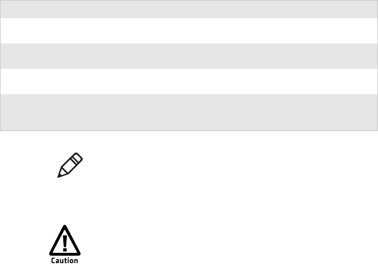
Data Communications Cable (P/N 226-270-XXX)
The printer has a 25-pin connector with the following pinout
designations and signal mnemonics:
PC Printer
RJ-11 Jack
Pin #
7
5
3
2
8
Pin #
6
5
3
2
1
9-Pin DSUB Male
Data Communications Cable (P/N 226-270-XXX)
5
1
9
616
Printer Communications Connector
15-Pin
D–Sub
25–Pin
D–Sub Signal Name Type I/O Description
1 NC NC – – – – – – NC (No Connection)
2 20 DSR (Data Set Ready) RS-232 IN Printer’s DSR
3 4 CTS (Clear To Send) RS-232 IN Wake up
4 2 RXD (Receive Data) RS-232 IN Printer’s RxD
5 3 TXD (Transmit Data) RS-232 OUT Printer’s TxD
6 5 RTS (Ready To Send) RS-232 OUT Printer’s RTS

Chapter 6 — Troubleshooting
124 6822 Series 80-Column Printer User’s Manual
7 6 DTR (Data Terminal
Ready) RS-232 OUT Printer’s DTR
8 9 HHC_CHARGE POWER OUT 11-13 V, 2 A maximum
9 7 GND POWER SG (Signal Ground)
Printer Communications Connector (continued)
15-Pin
D–Sub
25–Pin
D–Sub Signal Name Type I/O Description

6822 Series 80-Column Printer User’s Manual 125
ASpecifications
This appendix provides physical specifications for the 6822
printer models as well as specifications for the media used with
the printers.

Appendix A — Specifications
126 6822 Series 80-Column Printer User’s Manual
Specifications
Print Speed
230 cps
Weight
Fixed Mount Printers6.55 kg (14.41 lbs)
Portable Printers
w/ 4000 or 61XX terminal holder5.80 kg (12.75 lbs)
w/ 62XX, 600 series, 700 series, or CK60 holder5.67 kg (12.25 lbs)
Mounting plate1.93 kg (4.25 lbs)
Flat paper tray2.45 kg (5.40 lbs)
Compact paper tray2.05 kg (4.50 lbs)
Temperature
DC Operating -20°C to 60°C (-4°F to 140°F)
AC Operating -20°C to 45°C (-4°F to 113°F)
Storage -30°C to 70°C (-22°F to 158°F)
Humidity
Operating10 to 85% noncondensing
Storage5 to 95% noncondensing
Altitude
Operating–100 to 5000 m
Storage15,000 m
Electrical
Voltage13.8 VDC (nominal)
Current10 mA (idle, sleep mode not charging batteries);
3.5 A (average while printing);
450 mA (charging internal battery);
Up to 1.5 A (charging computer battery)
Vibration
12 g RMS for 4 hours
Note: Various print fonts do affect the print speed.

Appendix A — Specifications
6822 Series 80-Column Printer User’s Manual 127
ESD
15 kV noncontact and 8 kV contact
Battery Shelf Life
1 year at 25°C (77° F)
2.3 Ah
12 V sealed lead-acid)
Printer Dimensions
Listed below are the dimensions of the fixed mount and portable
printers.
Fixed Mount Printer
The base of the fixed mount printer is 32.5 cm (12.75 in) wide by
35.5 cm (14.0 in) front to back. The upper portion varies according to the
configurations shown in the following table.
Note: The battery goes dead within two weeks when connected
to the printer and with no external charge source.
Note: A printer and a computer, using the supplied serial cable,
can operate up to 9 m (30 ft) apart.
Fixed Mount Printer Dimensions
Configuration
(with deep paper tray) Width Length Depth
with 61XX Holder Side Mount 51.4 cm
(20.25 in) 36.8 cm
(14.5 in) 19.1 cm
(7.5 in)
with 4000 Series, 62XX, 600 Series, 700 Series, or CK60
Holder Side Mount 47.0 cm
(18.5 in) 36.8 cm
(14.5 in) 20.3 cm
(8.0 in)
with 61XX Holder Top Mount 42.5 cm
(16.75 in) 42.6 cm
(16.75 in) 19.1 cm
(7.5 in)
with 4000 Series, 62XX, 600 Series, 700 Series, or CK60
Holder Top Mount 38.1 cm
(15.0 in) 42.6 cm
(16.75 in) 20.3 cm
(8.0 in)
Appendix A — Specifications
128 6822 Series 80-Column Printer User’s Manual
Portable Printer
The portable printer may come with a handle, an AC foot, or with a
terminal holder top mount.
Media Specifications
The printer works with 1-3 ply carbonless paper that is single-edge glued
and designed for sprocket feed. Standard paper size is 8.5 x 11 in or 241
x 305 mm international (8.5 x 12 in). Use 3-ply forms up to a maximum
of 0.23 mm (0.009 in) thick.
A soft, flexible, rubber type cement applied to one perforation strip only
is preferred. The paper should wrap around a 1 1/4 in diameter roll
without curl or wrinkle.
Portable Printer Dimensions
Configuration Width Length Depth
with handle, 61XX Holder Top Mount, and Deep Paper
Tray 41.9 cm
(16.5 in) 42.6 cm
(16.8 in) 20.3 cm
(8.0 in)
with handle, 61XX Holder Top Mount, Shallow Paper Tray 42.5 cm
(16.8 in) 42.6 cm
(16.8 in) 19.1 cm
(7.5 in)
with handle, 4000 Series, 62XX, 600 Series, 700 Series, or
CK60 Holder Top Mount, and Deep Paper Tray 38.1 cm
(15.0 in) 42.6 cm
(16.8 in) 20.3 cm
(8.0 in)
with handle, 4000 Series, 62XX, 600 Series, or 700 Series,
or CK60 Holder Top Mount or Fill Plate, and Shallow Paper
Tray
41.9 cm
(16.5 in) 38.1 cm
(15.0 in) 13.0 cm
(5.1 in)
Note: The AC foot adds 6.35 cm (2.5 in) to the length of the
printer.
Using paper that matches the following specifications
ensures optimum 6822 performance. Variation from these
specifications, use of aged paper, or use of paper exposed to
elements such as dirt or humidity may cause printing
problems.

Appendix A — Specifications
6822 Series 80-Column Printer User’s Manual 129
Material Breakdown
The following tables show the material broken down per ply:
14# CBF (Carbonless Back and Front)
Target Under Over
Basis Weight 14 lb 13.3 lb 14.7 lb
Caliper 2.9 2.6 3.2
Moisture 5.0 4.0 6.0
Smoothness (RS) 165 110 230
Smoothness (CB) 270 220 320
Brightness (Wht) 88 86 90
Colors available: White, Canary, Pink, Goldenrod, Blue, Green
15# CF (Carbonless Front)
Target Under Over
Basis Weight 15 lb 14.43 lb 15.8 lb
Caliper 3.0 2.5 3.2
Moisture 5.0 4.0 6.0
Smoothness (RS) 140 100 180
Smoothness (CB) 140 100 180
Brightness (Wht) 85 84 86
Colors available: White, Canary, Pink, Goldenrod, Blue, Green
16# CB (Carbonless Back)
Target Under Over
Basis Weight 16 lb 15.2 lb 16.8 lb
Caliper 3.3 2.8 3.8
Moisture 5.7 4.2 6.7
Smoothness (RS) 180 120 270
Smoothness (CB) 270 220 320
Brightness (Wht) 86 84 88
Opacity (Wht) 81 78.5 82
Colors available: White, Canary, Pink, Goldenrod, Blue, Green

Appendix A — Specifications
130 6822 Series 80-Column Printer User’s Manual
Caliper Breakdown
The following table shows the caliper of forms broken down by ply:
20# OCR Laser Bond
Target Under Over
Basis Weight 20 lb 15.2 lb 16.8 lb
Caliper 4.0 3.8 4.2
Moisture 3.8 4.7 5.0
Smoothness 140 100 170
Brightness (Wht) 94 82 N/A
Opacity (Wht) 85 84 N/A
Caliper Breakdown
Target Maximum
1-Ply (20 lb) 4.0 4.2
2-Ply (15 lb and 16 lb) 6.3 7.0
3-Ply (14 lb, 15 lb, and 16 lb) 9.2 10.2
Appendix A — Specifications
6822 Series 80-Column Printer User’s Manual 131
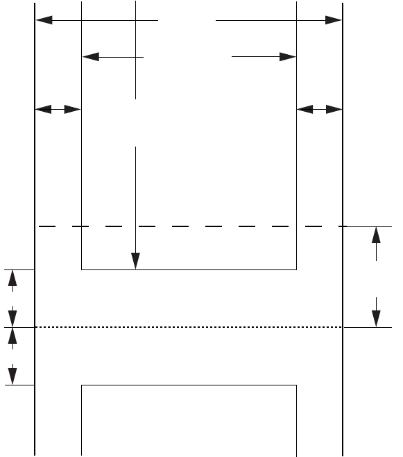
Understanding the Fanfold Paper Page Layout
The following illustration shows the printable area of the lower section
of a page of fanfold paper and the upper section of the next page. The
Assured Print Area is the best area to use for printing.
Printable Area of Fanfold Page
You should leave a 1 in margin at both the top and the bottom of the
page. This provides for a margin of six lines at 1/6 in line spacing. Even
though printing in Area 1 (before or after the perforation) may be
possible, you should keep in mind that paper feed precision is reliable
only within the Assured Print Area.
Page width
Paper End
Detection Position
Assured Print Area
55 lines max
(at 1/16” line spacing)
Perforation
Abcdef... ...Xyz
Abcdef... ...Xyz
Assured Print Area
8 inches Max.
(area 2)
0.75 inch
(or more)
(area 2)
0.75 inch
(or more)
(area 1)
1 inch
1 inch (area 1)
(area 3)
1.833 inches
(11 lines)
Appendix A — Specifications
132 6822 Series 80-Column Printer User’s Manual
•The top and bottom margins are represented by Area 1, as shown in
the previous illustration. The top margin is defined as the distance
between the top edge of the paper and the first row of printed
characters. The bottom margin is defined as the distance between the
last row of printed characters and the bottom edge of the paper.
•There is a possibility that printing can start within one line below the
perforation and printing could continue beyond the Assured Print
Area, however paper feed precision is only reliable with top and
bottom margins of approximately one inch. Basically, you should
consider there are only 55 lines available for reliable printing.
•The left and right margins are represented by Area 2. For reliable
printing, use a margin of at least 0.75 in for the left and right margins.
The Paper End Detection line indicates the point where the Paper Out
sensor detects the bottom edge of the paper.
Area 3 represents the distance between the Paper End Detection position
and the bottom edge of the page.
Once the last page of the fanfold paper stack is in the printer, and the
printhead has advanced past this Paper End Detection line, printing is no
longer reliable.
When the bottom end of the last page has advanced through the printer,
past the spring plate along the front of the platen, the paper should not
reverse back through the printer, because the printer could jam and cause
paper feed problems.