Intermec Technologies 07CN3 CN3 User Manual part 3
Intermec Technologies Corporation CN3 part 3
Contents
- 1. Compliance Insert
- 2. User Manual part 1 of 6
- 3. User Manual part 2 of 6
- 4. User Manual part 3 of 6
- 5. User Manual part 4 of 6
- 6. User Manual part 5 of 6
- 7. User Manual part 6 of 6
- 8. User Manual 1 of 6
- 9. User Manual 2 of 6
- 10. User Manual 3 of 6
- 11. User Manual 4 of 6
- 12. User Manual 5 of 6
- 13. User Manual 6 of 6
- 14. Manual
- 15. Radio Info
- 16. User Manual part 1
- 17. User Manual part 2
- 18. User Manual part 3
- 19. User Manual part 4
- 20. User Manual 1
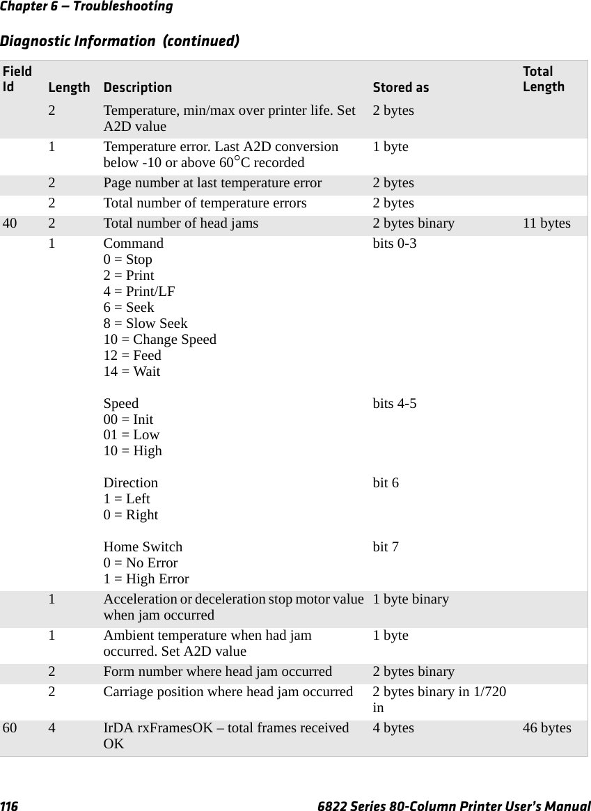
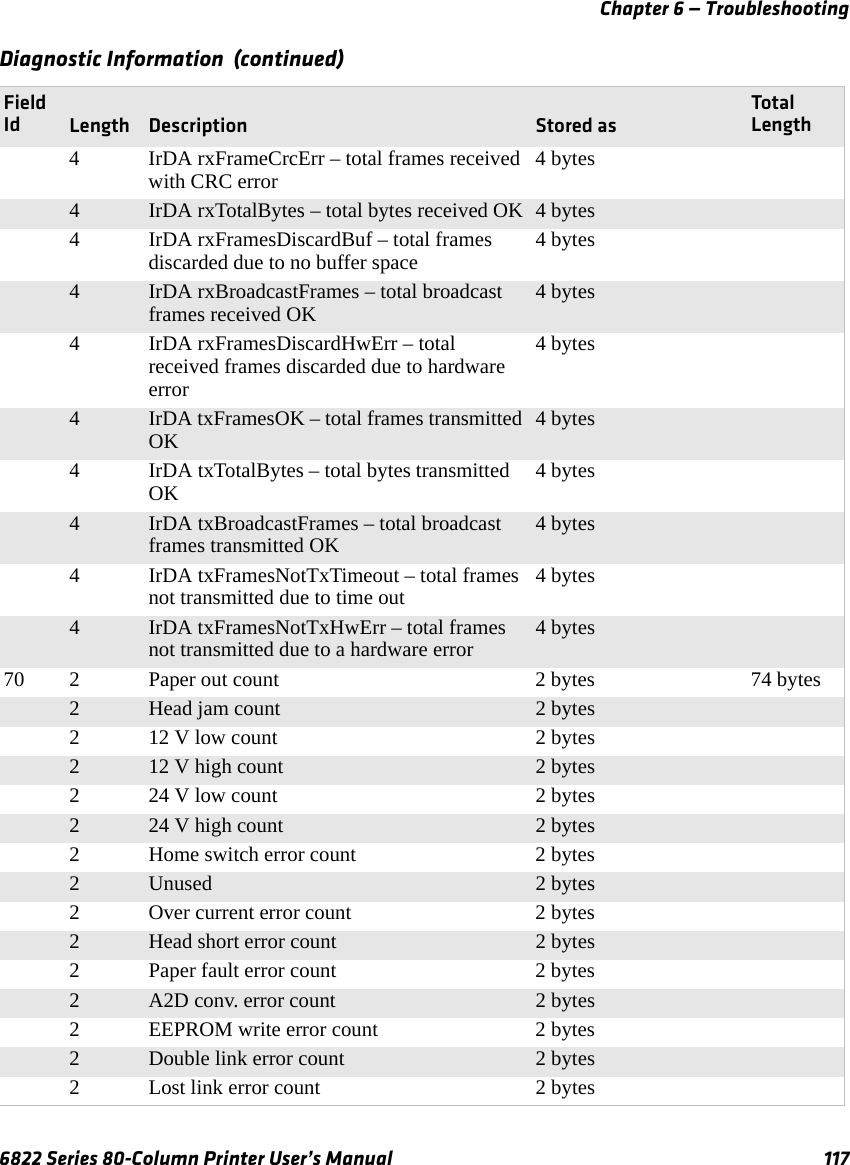
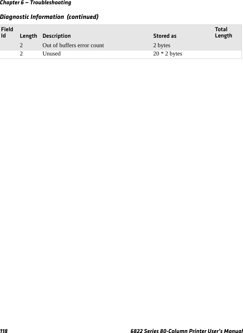
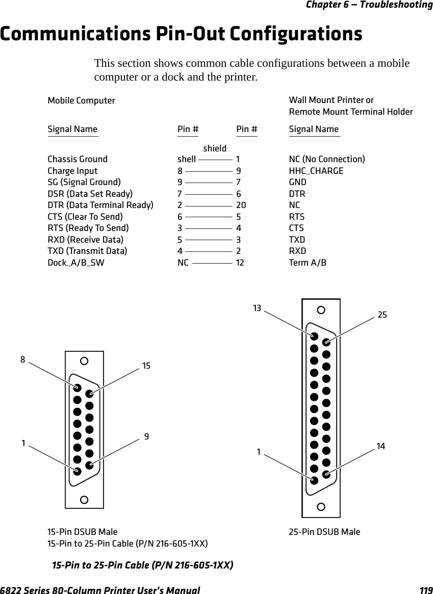
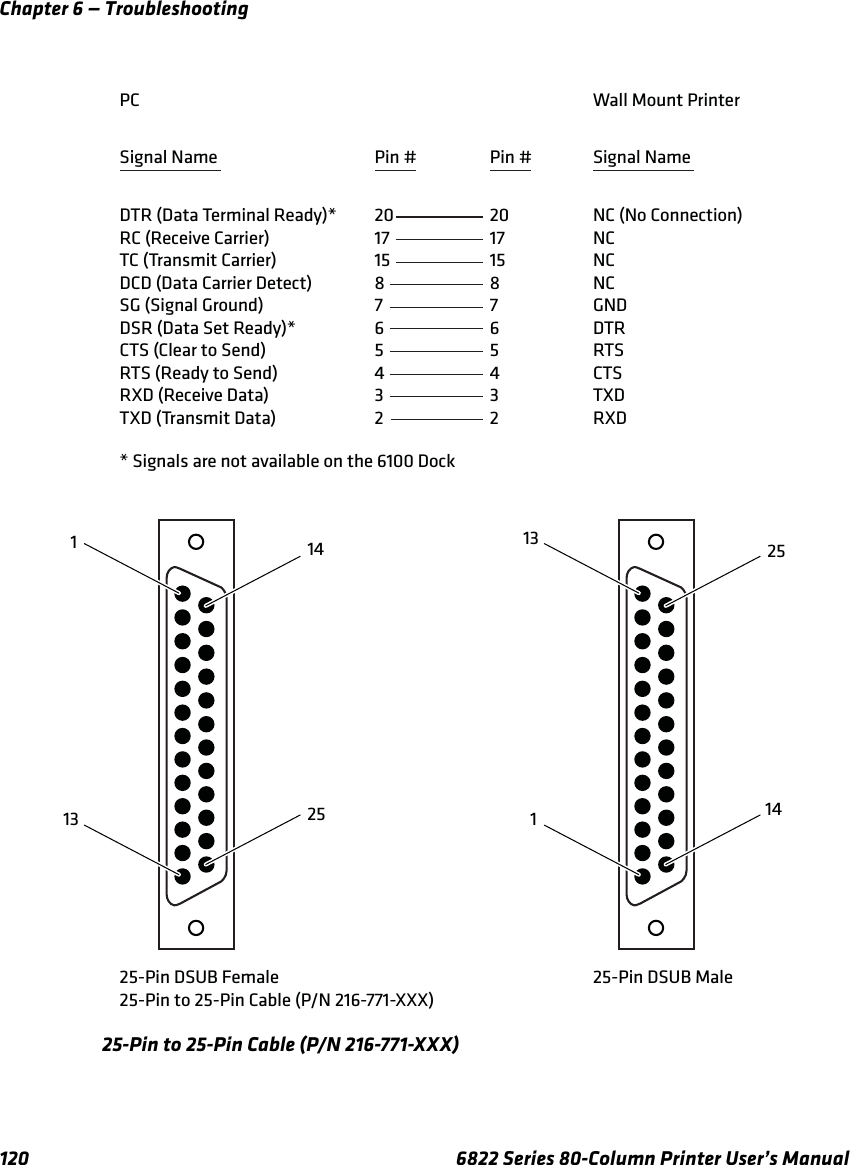
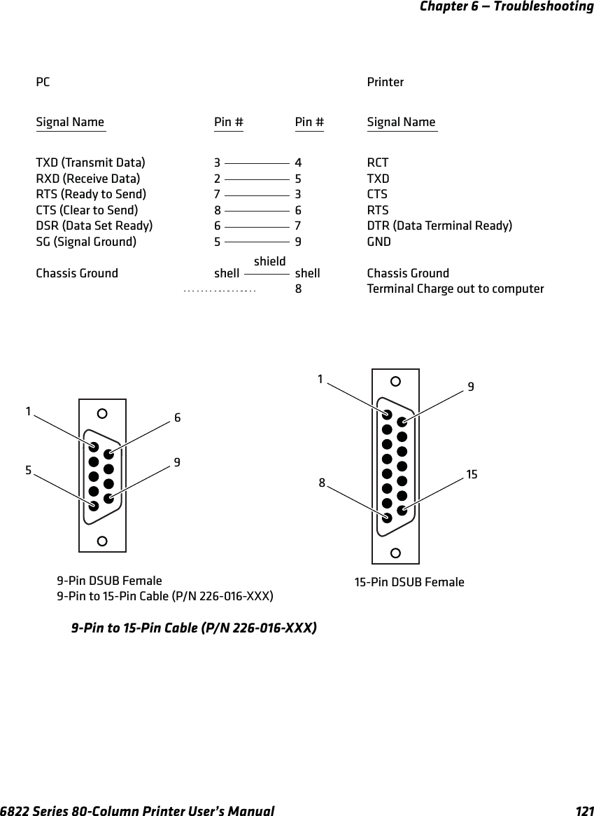
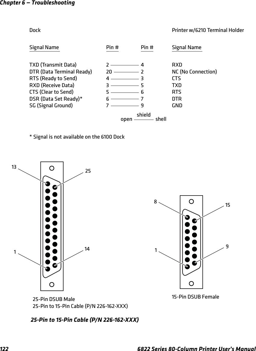
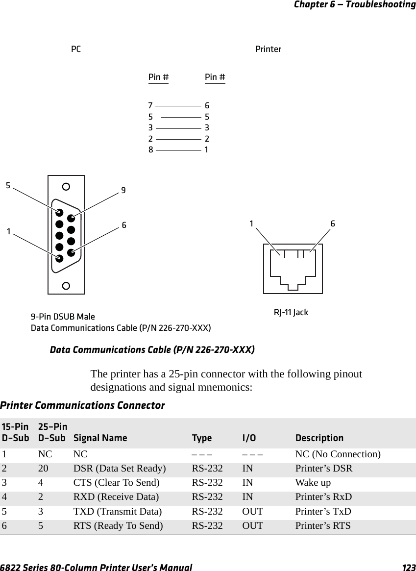
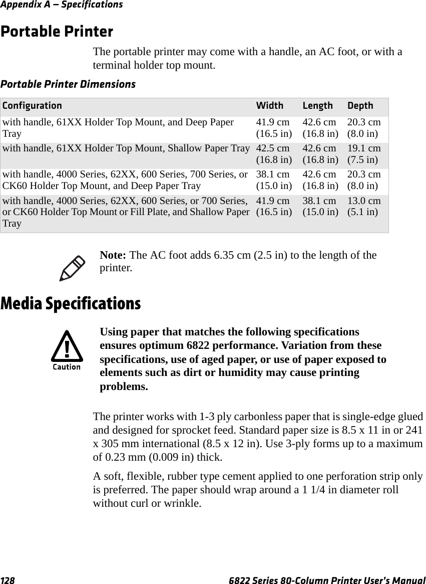
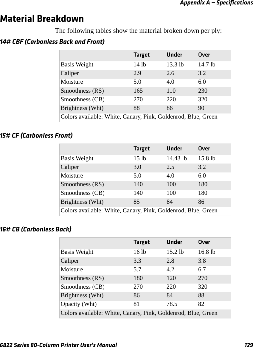
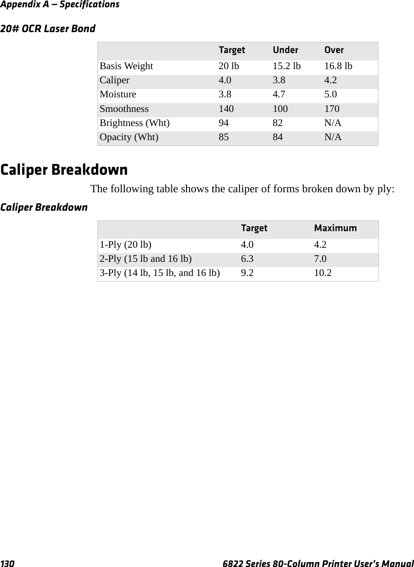
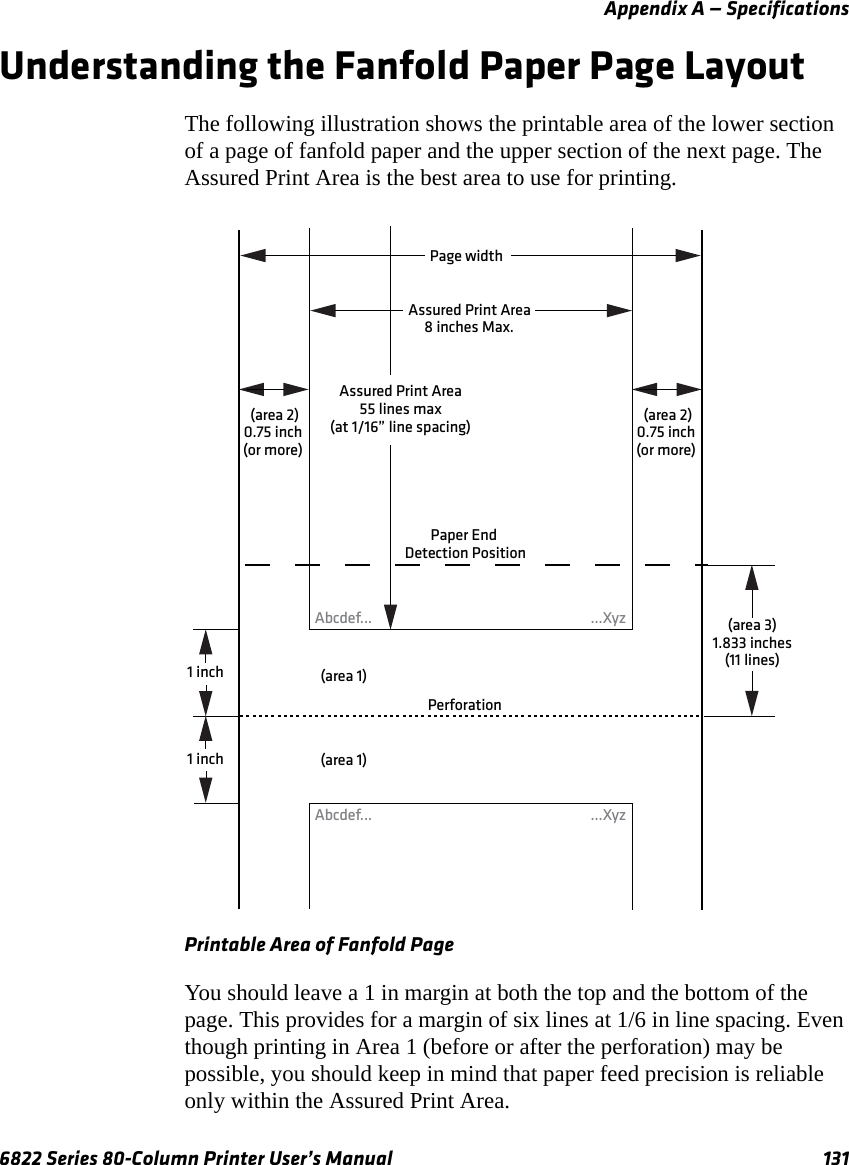
User Manual part 3
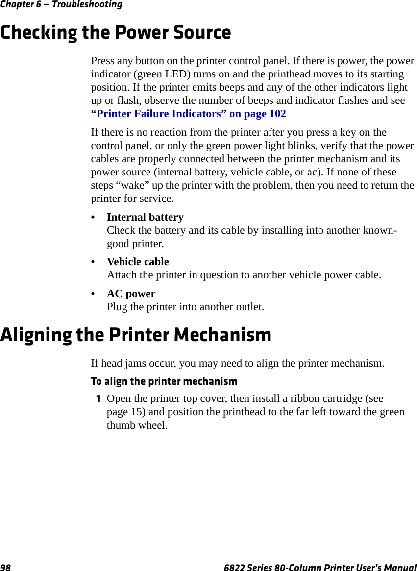
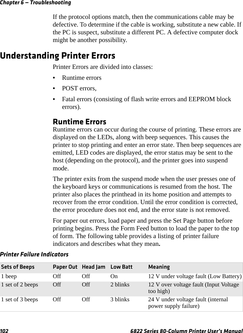
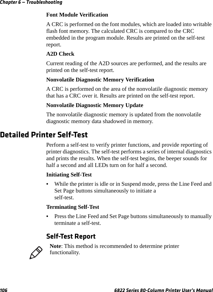
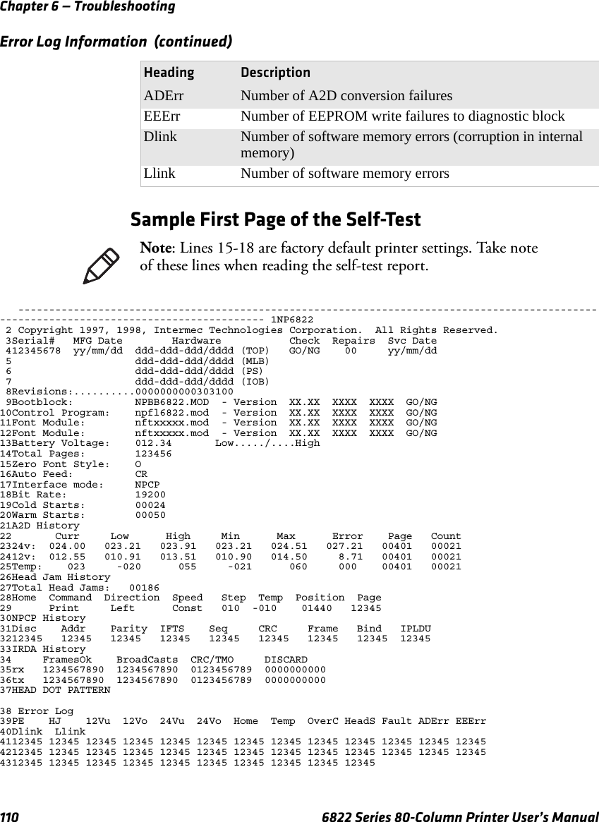
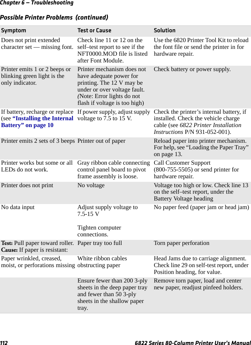
![Chapter 6 — Troubleshooting6822 Series 80-Column Printer User’s Manual 111Sample Second Page of the Self-TestPage 2 of the self-test contains the print pattern used to diagnose printer mechanical behavior. The pattern continuously prints the ASCII characters between 33 and 126 decimal inclusive for the entire page, or until you cancel the print by pressing a button on the printer. An example of that rotating pattern is shown below.!”#$%’()*+,–./0123456789:;<=>?@ABCDEFGHIJKLMNOPQRSTUVWXYZ[\]^_’abcdefghijklmnopqrstuvwxyz{|}~!”#$%’()*+,–./0123456789:;<=>?@ABCDEFGHIJKLMNOPQRSTUVWXYZ[\]^_’abcdefghijklmnopqrstuvwxyz{|}~!”#$%’()*+,–./0123456789:;<=>?@ABCDEFGHIJKLMNOPQRSTUVWXYZ[\]^_’abcdefghijklmnopqrstuvwxyz{|}~!”#$%’()*+,–./0123456789:;<=>?@ABCDEFGHIJKLSelf-Test Failure•For help, see “Miscellaneous Troubleshooting Tips” on page 111.•Check the power source (internal battery, charge cable, or ac adaptor) for a possible power failure.Miscellaneous Troubleshooting TipsThe following table lists actual printing problems, possible causes, and actions you should take to correct a problem.Possible Printer Problems Symptom Test or Cause SolutionPrinter does not communicate with the mobile computer. Bluetooth unable to connect.Incorrect protocol selection. Check lines 17 and 18 on the self-test report for correct bit rate and protocol selection. Change protocol settings through configuration process.Make sure you are in range (10 cm to 10 m) Make sure your device is configured to be discoverable and/or connectable. For help, see “Bluetooth Configuration Commands and Specifications” on page 133.Make sure the Bluetooth shutdown timer has not expired Double-spacing on application reports but single-spacing on self-test.Check line 16 on the self-test report. CR+LF indicates an incorrect configuration for NPCP.For help, see “Cleaning the Mask Spring” on page 22.Zero prints incorrectly (with or without slash). Check line 15 on the self–test report for the Zero Font Style setting.If incorrect, adjust the zero print option, see “Cleaning the Mask Spring” on page 22](https://usermanual.wiki/Intermec-Technologies/07CN3.User-Manual-part-3/User-Guide-935673-Page-17.png)