Intermec Technologies 2610CF 2610CF User Manual legal
Intermec Technologies Corporation 2610CF legal
Contents
700C User Manual 1 of 3
700 Series Color
Mobile Computer
User's Manual

ii 700 Series Color Mobile Computer User’s Manual
Intermec Technologies Corporation
Corporate Headquarters Technical Communications Department
6001 36th Ave. W. 550 Second Street SE
Everett, WA 98203 Cedar Rapids, IA 52401
U.S.A. U.S.A.
www.intermec.com
The information contained herein is proprietary and is provided solely for the purpose of allowing customers
to operate and service Intermec-manufactured equipment and is not to be released, reproduced, or used for
any other purpose without written permission of Intermec.
Information and specifications contained in this document are subject to change without prior notice and do
not represent a commitment on the part of Intermec Technologies Corporation.
E2002-2004 by Intermec Technologies Corporation. All rights reserved.
The word Intermec, the Intermec logo, Norand, ArciTech, CrossBar, Data Collection Browser, dcBrowser,
Duratherm, EasyCoder, EasyLAN, Enterprise Wireless LAN, EZBuilder, Fingerprint, i-gistics, INCA (under
license), InterDriver, Intermec Printer Network Manager, IRL, JANUS, LabelShop, Mobile Framework,
MobileLAN, Nor*Ware, Pen*Key, Precision Print, PrintSet, RoutePower, TE 2000, Trakker Antares, UAP,
Universal Access Point, and Virtual Wedge are either trademarks or registered trademarks of Intermec
Technologies Corporation.
Throughout this manual, trademarked names may be used. Rather than put a trademark (™or ®) symbol in
every occurrence of a trademarked name, we state that we are using the names only in an editorial fashion,
and to the benefit of the trademark owner, with no intention of infringement.
There are U.S. and foreign patents pending.
Microsoft, Windows, and the Windows logo are registered trademarks of Microsoft Corporation in the
United States and/or other countries.
Bluetooth is a trademark of Bluetooth SIG, Inc., U.S.A.
This product includes software developed by the OpenSSL Project for use in the OpenSSL Toolkit
(www.opensssl.org).
This product includes cryptographic software written by Eric Young (EAY@cryptsoft.com).
Wi-Fi is a registered certification mark of the Wi-Fi Alliance.

iii700 Series Color Mobile Computer User’s Manual
Document Change Record
This page records changes to this document. The document was originally released as Revision A.
Revision Date Description of Change
B11/2002 Added information about the Siemens MC45 radio module, the tethered scanner, CAB
extraction, FTP Server parameters, and Data Collection control panel applet imager op-
tions.
C04/2003 Added information about the ambient light sensor, the beeper, keypad sequences, the
alphanumeric keypad, the vibrator, an accessories list, programming notifications, the
MaxiCode symbology, the Utilities control panel applet, and the Wireless Network con-
trol panel applet.
D08/2003 Upgraded Pocket PC 2002 information to Windows Mobile 2003, upgraded all illustra-
tions to gray-scale, added new Imager functions, moved the Automatic Data Collection
COM Interface material to the SDK User’s Manual.
E01/2004 Added 730 Computer information, revised CDMA Setup information, and revised Wire-
less Area Network Printing information.
F04/2004 Updated 802.11 security supplicant information. Added new network selection APIs.
Incorporated information about the Intermec Settings control panel applet for PSM
Builds 3.00 or newer. Added information about the PhoneUtility application. Revised
Chapter 4, “Network Support.” Added tethered scanner and internal scanner configura-
tion and troubleshooting information to Chapter 6, “Scanner Support.”
G01/2005 Added information about resetting the 700 Series Computer. Updated the Profile Wizard
information in Appendix A, “Configurable Settings.” Revised information about using
Sprint Watcher and added information about a Phone application for units with CDMA
or GSM radios in Chapter 4, “Network Support.” Added information about the 741, 751,
and 761 Computers and the MC46 Radio.
iv 700 Series Color Mobile Computer User’s Manual
Contents
v700 Series Color Mobile Computer User’s Manual
Contents
Before You Begin xix.............................................................
Safety Summary xix.......................................................
Donotrepairoradjustalone xix.......................................
First aid xix.......................................................
Resuscitation xix...................................................
Energized equipment xix.............................................
Safety Icons xx...........................................................
Global Services and Support xxi..............................................
Warranty Information xxi............................................
Web Support xxi...................................................
Telephone Support xxi...............................................
WhoShouldReadthisManual? xxii..........................................
Related Documents xxii....................................................
Introduction
1...............................................................
Ambient Light Sensor 2..........................................................
Audio System 3.................................................................
Speaker 3...............................................................
Microphone 4...........................................................
External Headset Jack 4....................................................
Battery 5......................................................................
Beeper 7......................................................................
Enable the Beeper 7.......................................................
Disable the Scanner Mute 8.................................................
Select a Beeper Volume 9...................................................
Disable the Beeper 10.....................................................
Keypad 11.....................................................................
Backlight for Keypad 11....................................................
Key Sequences 12.........................................................
[Gold] or [Gold/White] Plane Keys 12..................................
Alpha (Blue) Plane Keys 14...........................................
Modem Support 16..............................................................
PSM Build Version 16...........................................................
Resetting Your 700 Color Computer 17..............................................
Software Build Version 18.........................................................
1
Contents
vi 700 Series Color Mobile Computer User’s Manual
Storage Media 19...............................................................
CompactFlash Cards 19....................................................
Secure Digital Cards 19....................................................
Vibrator 20....................................................................
Wireless Network Support 21......................................................
Accessories 22..................................................................
What’s New 22.................................................................
Windows Mobile 2003
23....................................................
Software Builds 24..............................................................
Where to Find Information 25.....................................................
Basic Skills 26..................................................................
Today Screen 26..........................................................
Programs 27.............................................................
Navigation Bar and Command Bar 28.........................................
Pop-up Menus 29........................................................
Notifications 29..........................................................
Entering Information 30...................................................
Typing With the Onscreen Keyboard 31................................
Using Block Recognizer 32...........................................
Using Letter Recognizer 33...........................................
Using Transcriber 33................................................
Selecting Typed Text 33.............................................
Writing on the Screen 34...................................................
Selecting the Writing 34.............................................
Converting Writing to Text 35........................................
Drawing on the Screen 37..................................................
Creating a Drawing 37..............................................
Selecting a Drawing 37..............................................
Recording a Message 38....................................................
Creating a Recording 38.............................................
Using My Text 39........................................................
Finding and Organizing Information 40.......................................
Customizing Your 700 Color Computer 41.....................................
Adjusting Settings 41...............................................
Adding or Removing Programs 41.....................................
Microsoft ActiveSync 44..........................................................
2
Contents
vii700 Series Color Mobile Computer User’s Manual
Microsoft Pocket Outlook 46......................................................
Calendar: Scheduling Appointments and Meetings 46.............................
Synchronizing Calendar 47...........................................
Why Use Categories in the Calendar? 47................................
What’s an All Day Event? 48.........................................
What’s a Recurrence Pattern? 49.......................................
Viewing Appointments 49............................................
Creating or Changing an Appointment 51...............................
Creating an All Day Event 52.........................................
Setting a Reminder for an Appointment 53...............................
Adding a Note to an Appointment 54...................................
Making an Appointment Recurring 55..................................
Assigning an Appointment to a Category 56..............................
Sending a Meeting Request 57........................................
Finding an Appointment 58..........................................
Deleting an Appointment 58..........................................
Changing Calendar Options 59.......................................
Contacts: Tracking Friends and Colleagues 60...................................
Creating a Contact 61...............................................
Synchronizing Contacts 61...........................................
Viewing Contacts 62................................................
Creating or Changing a Contact 63....................................
Adding a Note to a Contact 64........................................
Assigning a Contact to a Category 65...................................
Copying a Contact 65...............................................
Sending a Message to a Contact 66.....................................
Finding a Contact 67...............................................
Deleting a Contact 67...............................................
Adding a Contact to Speed Dial 68.....................................
Changing Contacts Options 68........................................
Tasks: Keeping a To Do List 69..............................................
Creating a Task 70.................................................
Synchronizing Tasks 70..............................................
Notes: Capturing Thoughts and Ideas 71......................................
Creating a Note 71.................................................
Synchronizing Notes 72.............................................
Inbox: Sending and Receiving E-mail Messages 73...............................
Synchronizing E-mail Messages 73.....................................
Managing E-mail Messages and Folders 74...............................
Connecting to a Mail Server 75........................................
Composing and Sending Messages 77...................................
Companion Programs 78.........................................................
Pocket Word 78..........................................................
Creating a Document 78.............................................
Typing Mode 79...................................................
Writing Mode 80..................................................
Recording Mode 80................................................
Drawing Mode 81..................................................
Synchronizing Pocket Word Documents 81..............................
Pocket Excel 82..........................................................
Creating a Workbook 82
.............................................
Tips for Working in Pocket Excel 83...................................
Contents
viii 700 Series Color Mobile Computer User’s Manual
MSN Messenger 84.......................................................
Setting Up an Account 85............................................
Signing In and Out 85..............................................
Working with Contacts 86...........................................
Managing Contacts 87..............................................
Sending a Message 88...............................................
Windows Media Player for Windows Mobile 89.................................
Microsoft Reader 90.......................................................
Getting Books on Your 700 Color Computer 90..........................
Using the Library 91................................................
Reading a Book 92.................................................
Using Reader Features 93............................................
Removing a Book 93................................................
Pocket Internet Explorer 94........................................................
TheMobileFavoritesFolder 94..............................................
Favorite Links 94.........................................................
Mobile Favorites 95.......................................................
Using AvantGo Channels 96................................................
Using Pocket Internet Explorer 96............................................
Viewing Mobile Favorites and Channels 97..............................
Browsing the Internet 97.............................................
Getting Connected 98............................................................
Connecting to an Internet Service Provider 98...................................
Connecting to Work 102...................................................
Creating a Modem Connection to Work 103.............................
Creating a Wireless Network Connection 106............................
Creating a VPN Server Connection to Work 111..........................
Ending a Connection 113..................................................
Connecting Directly to an E-mail Server 114....................................
Setting Up an E-mail Account 114...........................................
Installing Applications
117..................................................
Packaging an Application 118......................................................
Installing Applications 119........................................................
Using Microsoft ActiveSync 119.............................................
Using the FTP Server 120..................................................
Using a Storage Card 120..................................................
Copying to a CompactFlash Card 120..................................
Copying to a Secure Digital Storage Card 121............................
Updating the System Software 121..................................................
Application Migration 122........................................................
Migrating from a 700 Monochrome Computer 124.....................................
3
Contents
ix700 Series Color Mobile Computer User’s Manual
Installing Cabinet Files 124........................................................
Network Support
125........................................................
Understanding Your 700 Series Computer 126.........................................
Antennas (760/761 Computers) 127.................................................
Network Adapters 127...........................................................
Ethernet Communications (740, 741, 750, 751, 760, 761 Computers) 128............
Wireless 802.11 Communications 129.........................................
No Networking 130.......................................................
Network Selection APIs 130.......................................................
Network Connections 131........................................................
CORE (760, 761 Computers with WAN Radios) 132...................................
Activating CORE 132.....................................................
Install an Available Radio Module 132.........................................
Loading a Radio Module 133................................................
802.11 CF CORE Module 133..............................................
General 134......................................................
Details 135.......................................................
CDMA/1xRTT CORE Module (760 Computers with WAN Radios) 135.............
WAN Monitor — General 136........................................
WAN Monitor — Details 137........................................
GSM/GPRS CORE Module (760 Computers with WAN Radios) 138................
WAN Monitor — General 138........................................
WAN Monitor — Details 139........................................
Microsoft Phone Application (761 Computers with CDMA Radios) 140.....................
Data Provisioning (Sprint) 140..............................................
Phone Application 143.....................................................
Speed Dial 144....................................................
Call History 144...................................................
Tools 145........................................................
Phone Settings 146.................................................
Microsoft Phone Application (761 Computers with GSM Radios) 149......................
Activation 149...........................................................
Phone Application 149.....................................................
Call History 150...................................................
Speed Dial 150....................................................
Tools 151........................................................
Phone Settings 151.................................................
4
Contents
x 700 Series Color Mobile Computer User’s Manual
PhoneUtility (760 Computers with GPRS Radios) 154..................................
Audio Mode 154.........................................................
Notification 155..........................................................
Advanced Audio 155......................................................
SB555 Watcher (760 Computers with CDMA Radios) 157...............................
Copying CDMA Radio Module CAB Files from Intermec Web Site 157..............
Via Microsoft ActiveSync 158...............................................
Via a CompactFlash or Secure Digital Storage Card 158...........................
Finishing the Installation 159...............................................
Activation 160...........................................................
Verizon Automated Activation Process 163.....................................
Sprint Automated Activation Process 167......................................
Download and Activate Sprint Watcher 167..............................
Using Sprint Watcher 170...........................................
Data Provisioning 173..............................................
Telus and Bell Mobility Activation 176........................................
AT Command Interface (760 Computers) 177..................................
Command Set for Sierra Wireless SB555 177.............................
Command Set for Siemens MC45 or MC46 177..........................
Testing the AT Commands 178.......................................
Wireless Personal Area Networking 182..............................................
Documentation 182.......................................................
About the Application 182..................................................
Mode 182........................................................
Wireless Printing 183...............................................
File Transfer 184...................................................
AutoIP/DHCP 186..............................................................
SNMP Configuration on the 700 Color Computer 187..................................
Management Information Base 187...........................................
Object Identifiers 188.....................................................
Configuring with SNMP 188...............................................
Printer Support
189..........................................................
Printing ASCII 190..............................................................
Directly to a Port 190.....................................................
Directly to a Generic Serial Port 190..........................................
IrDA Printer Driver 190..........................................................
5
Contents
xi700 Series Color Mobile Computer User’s Manual
NPCP Printer Driver 191.........................................................
About NPCP 191........................................................
NPCP Driver Installation and Removal 191....................................
Opening the NPCP Driver 192..............................................
Closing the NPCP Driver 192...............................................
Reading from the NPCP Driver 192..........................................
Writing to the NPCP Driver 192.............................................
NPCP Driver I/O Controls 193..............................................
NPCP Printer Communications 194..........................................
Sample Code 194.........................................................
NPCP Error Codes 195....................................................
O’Neil Printer Driver 196.........................................................
DTR Driver Installation and Removal 196.....................................
Opening the DTR Driver 197...............................................
Closing the DTR Driver 197................................................
Writing to the DTR Driver 197..............................................
DTR Printer Communications 197...........................................
Scanner Support
199.........................................................
Scanner Control and Data Transfer 200..............................................
Data Collection Configuration 201..................................................
Internal Scanners 202............................................................
For Units With PSM Build 3.00 or Newer 202..................................
Scanner and Imager Settings 203.............................................
Internal Scanner Supported Symbologies 203....................................
Tethered Scanners 204...........................................................
For Units With PSM Builds Older than 3.00 204................................
Enabling and Disabling 204..........................................
Error Message 205.................................................
Changing Comm Settings 205........................................
Scanner Cabling 207................................................
Limitations and Capabilities 207.......................................
For Units With PSM Build 3.00 or Newer 209..................................
Configuring the Tethered Scanner 209..................................
Troubleshooting the 1551E/1553 Tethered Scanner 212....................
Reset Factory Defaults 212...........................................
Tethered Scanner Supported Symbologies 213...................................
6
Contents
xii 700 Series Color Mobile Computer User’s Manual
Programming
215............................................................
Creating CAB Files 216..........................................................
Creating Device-Specific CAB Files 216.......................................
Creating an .INF File 216............................................
Sample .INF File 225...............................................
Using Installation Functions in SETUP.DLL 228................................
After the CAB File Extraction 228............................................
Creating CAB Files with CAB Wizard 231.....................................
Troubleshooting the CAB Wizard 232.........................................
Customization and Lockdown 233..................................................
FTP Server 234.................................................................
Configurable Parameters Via the Registry Editor 235.............................
BlockSize 235.....................................................
DeviceName 235..................................................
DeviceURL 235...................................................
IDNATarget 236..................................................
ManifestName 236.................................................
PauseAtStartup 236.................................................
Root 236.........................................................
Transferring Files Over TCP/IP Networks 237..................................
Stopping the FTP Server from Your Application 240..............................
Autostart FTP 240........................................................
Kernel I/O Controls 242..........................................................
IOCTL_HAL_GET_DEVICE_INFO 242.....................................
IOCTL_HAL_ITC_READ_PARM 243.......................................
IOCTL_HAL_ITC_WRITE_SYSPARM 247...................................
IOCTL_HAL_GET_DEVICEID 249........................................
IOCTL_HAL_GET_OAL_VERINFO 250....................................
IOCTL_HAL_GET_BOOTLOADER_VERINFO 251..........................
IOCTL_HAL_WARMBOOT 252...........................................
IOCTL_HAL_COLDBOOT 252............................................
IOCTL_HAL_GET_RESET_INFO 253......................................
IOCTL_HAL_GET_BOOT_DEVICE 254....................................
IOCTL_HAL_REBOOT 255...............................................
IOCTL_PROCESSOR_INFORMATION 256.................................
IOCTL_GET_CPU_ID 257................................................
7
Contents
xiii700 Series Color Mobile Computer User’s Manual
Network Selection APIs 258.......................................................
Basic Connect/Disconnect Functions 260......................................
RadioConnect() 260................................................
RadioDisconnect() 260..............................................
RadioDisassociate() 261.............................................
Query Information Functions 261............................................
GetAssociationStatus() 261...........................................
GetAuthenticationMode() 262........................................
GetBSSID() 262...................................................
GetDiversity() 263.................................................
GetLinkSpeed() 263................................................
GetMac() 264.....................................................
GetNetworkMode() 264.............................................
GetNetworkType() 265..............................................
GetSSID() 265....................................................
GetPowerMode() 266...............................................
GetRSSI() 266....................................................
GetTXPower() 267.................................................
GetWepStatus() 268................................................
GetRadioIpAddress() 269............................................
GetCCXStatus() 269................................................
Set Information Functions 270..............................................
AddWep() 270....................................................
EnableWep() 270..................................................
EncryptionStatus() 271..............................................
SetAuthenticationMode() 272.........................................
SetChannel() 272..................................................
SetNetworkMode() 273.............................................
SetPowerMode() 273................................................
SetSSID() 274.....................................................
SetCCXStatus() 274................................................
SetMixedCellMode() 274............................................
RemoveWep() 275.................................................
Helper Functions 275.....................................................
ConfigureProfile() 275..............................................
EnableZeroConfig() 276.............................................
isZeroConfigEnabled() 276...........................................
isOrinoco() 276....................................................
isSupplicantRunning() 277...........................................
StartScanList() 277.................................................
StartSupplicant() 277...............................................
StopSupplicant() 278...............................................
isDHCPEnabled() 278..............................................
RenewDHCP() 278................................................
GetCurrentDriverName() 279........................................
ResetRadioToSystemSave() 279.......................................
EnableSuppLogging() 279............................................
SwitchPacketDriver() 280............................................
Deprecated Functions 280..................................................
Contents
xiv 700 Series Color Mobile Computer User’s Manual
Notifications 281...............................................................
NLEDGetDeviceInfo 282..................................................
NLEDSetDevice 282......................................................
Reboot Functions 283............................................................
IOCTL_HAL_REBOOT 283...............................................
IOCTL_HAL_COLDBOOT 283............................................
IOCTL_HAL_WARMBOOT 283...........................................
Remapping the Keypad 284.......................................................
Unshifted Plane 284.......................................................
Gold Plane 284..........................................................
Alpha (Blue) Plane 285....................................................
Key Values 285..........................................................
Numeric Keypad 285...............................................
Alphanumeric Keypad 285...........................................
How Key Values Are Stored in Registry 286....................................
Change Notification 286...................................................
Advanced Keypad Remapping 286............................................
Scan Codes 287..........................................................
Numeric Keypad 287...............................................
Alphanumeric Keypad 288...........................................
Sample View of Registry Keys 290............................................
Configurable Settings
291...................................................
Configuration Parameters 292......................................................
Changing a Parameter Setting 292............................................
About Configuration Parameters 293..........................................
Data Collection Control Panel Applet 294............................................
Symbologies 295.........................................................
Code 39 296......................................................
Standard 2 of 5 297.................................................
Codabar 298......................................................
UPC/EAN 299....................................................
Code 93 300......................................................
Code 128 301.....................................................
Plessey 304.......................................................
MSI 305.........................................................
PDF417 306......................................................
Interleaved 2 of 5 309...............................................
Matrix 2 of 5 310..................................................
Telepen 311......................................................
Code 11 312......................................................
QR Code 313.....................................................
Data Matrix 314...................................................
MaxiCode 315....................................................
A
Contents
xv700 Series Color Mobile Computer User’s Manual
Symbology Options 316....................................................
Symbology ID 316.................................................
Prefix 322........................................................
Suffix 323........................................................
Beeper/LED 324.........................................................
Beeper 325.......................................................
Beeper Volume 326.................................................
Beeper Frequency 327...............................................
Good Read Beeps 328...............................................
Good Read Beep Duration 329........................................
Imager 330..............................................................
Aimer LED Duration 330............................................
Sticky Aimer Duration 331...........................................
Image Dimension 332...............................................
Lighting Mode 333.................................................
1D OmniDir Decode Enable 334......................................
Virtual Wedge 335........................................................
Virtual Wedge 335.................................................
Preamble 336.....................................................
Postamble 338.....................................................
Grid 340.........................................................
Code Page 341....................................................
Intermec Settings Control Panel Applet 342...........................................
SNMP Control Panel Applet 343...................................................
Security 344.............................................................
Read Only Community 344..........................................
Read/Write Community 345.........................................
Read Encryption 346...............................................
Write Encryption 347...............................................
Encryption Key 348................................................
Traps 349...............................................................
Authentication 349.................................................
Threshold 350.....................................................
Identification 351.........................................................
Contact 351......................................................
Name 352........................................................
Location 353......................................................
Unit Information Control Panel Applet 354...........................................
Versions 354............................................................
Battery Status 355........................................................
CAB Files 356...........................................................
Utilities Control Panel Applet 358..................................................
Dock Switch 358.........................................................
Registry Save 359.........................................................
Wakeup Mask 360........................................................
App Launch 361.........................................................
Contents
xvi 700 Series Color Mobile Computer User’s Manual
Wireless Network Control Panel Applet 363...........................................
About the Wireless Network 363.............................................
Terminology 363.........................................................
Configuring Your Wireless Network 365.......................................
Basic 366.........................................................
Security 367......................................................
Advanced 384.....................................................
Other Configurable Parameters 385.................................................
Audio Volume 385........................................................
Automatic Shutoff 385.....................................................
Backlight Timeout 386....................................................
Date/Time 386..........................................................
Key Clicks 386...........................................................
Using Reader Commands 387......................................................
Change Configuration 387.................................................
Set Time and Date 388....................................................
Configuration Bar Codes 389......................................................
Audio Volume 389........................................................
Automatic Shutoff 390.....................................................
Backlight Timeout 390....................................................
Key Clicks 391...........................................................
Virtual Wedge Grid, Preamble, Postamble 392..................................
Grid 392.........................................................
Preamble 392.....................................................
Postamble 392.....................................................
Bar Code Symbologies
393..................................................
Codabar 394...................................................................
Code 11 394...................................................................
Code 39 394...................................................................
Encoded Code 39 (Concatenation) 395........................................
Encoded Code 39 (Full ASCII) 395...........................................
Code 93 395...................................................................
Code 128 396..................................................................
Data Matrix 397................................................................
EAN (European Article Numbering) 397.............................................
B
Contents
xvii700 Series Color Mobile Computer User’s Manual
I 2 of 5 (Interleaved) 398.........................................................
Matrix 2 of 5 398...............................................................
MaxiCode 398.................................................................
PDF417 398...................................................................
Plessey 399....................................................................
QR Code (Quick Response Code) 400...............................................
S2of5(Standard2of5) 400......................................................
Telepen 401...................................................................
UPC (Universal Product Code) 401.................................................
Index
Classes and Functions 404........................................................
General Index 410...............................................................
Files Index 426.................................................................
I
Contents
xviii 700 Series Color Mobile Computer User’s Manual
Before You Begin
xix700 Series Color Mobile Computer User’s Manual
Before You Begin
This section provides you with safety information, technical support
information, and sources for additional product information.
Safety Summary
Your safety is extremely important. Read and follow all warnings and
cautions in this document before handling and operating Intermec
equipment. You can be seriously injured, and equipment and data can be
damaged if you do not follow the safety warnings and cautions.
Donotrepairoradjustalone
Do not repair or adjust energized equipment alone under any
circumstances. Someone capable of providing first aid must always be
present for your safety.
First aid
Always obtain first aid or medical attention immediately after an injury.
Never neglect an injury, no matter how slight it seems.
Resuscitation
Begin resuscitation immediately if someone is injured and stops breathing.
Any delay could result in death. To work on or near high voltage, you
should be familiar with approved industrial first aid methods.
Energized equipment
Never work on energized equipment unless authorized by a responsible
authority. Energized electrical equipment is dangerous. Electrical shock
from energized equipment can cause death. If you must perform
authorized emergency work on energized equipment, be sure that you
comply strictly with approved safety regulations.

Before You Begin
xx 700 Series Color Mobile Computer User’s Manual
Safety Icons
This section explains how to identify and understand dangers, warnings,
cautions, and notes that are in this manual. You may also see icons that tell
you when to follow ESD procedures and when to take special precautions
for handling optical parts.
A warning alerts you of an operating procedure, practice, condition,
or statement that must be strictly observed to avoid death or serious
injury to the persons working on the equipment.
Avertissement: Un avertissement vous avertit d’une procédure de
fonctionnement, d’une méthode, d’un état ou d’un rapport qui doit
être strictement respecté pour éviterl’occurrencedemortoude
blessures graves aux personnes manupulant l’équipement.
A caution alerts you to an operating procedure, practice, condition, or
statement that must be strictly observed to prevent equipment damage
or destruction, or corruption or loss of data.
Attention: Une précaution vous avertit d’une procédure de
fonctionnement, d’une méthode, d’un état ou d’un rapport qui doit
être strictement respecté pour empêcher l’endommagement ou la
destruction de l’équipement, ou l’altération ou la perte de données.
Note: Notes either provide extra information about a topic or contain
special instructions for handling a particular condition or set of
circumstances.

Before You Begin
xxi700 Series Color Mobile Computer User’s Manual
Global Services and Support
Warranty Information
To understand the warranty for your Intermec product, visit the Intermec
web site at www.intermec.com and click Service & Support.TheIntermec
Global Sales & Service page appears. From the Service & Support menu,
move your pointer over Support,andthenclickWarranty.
Disclaimerofwarranties:Thesamplecodeincludedinthisdocumentis
presented for reference only. The code does not necessarily represent
complete, tested programs. The code is provided “as is with all faults.” All
warranties are expressly disclaimed, including the implied warranties of
merchantability and fitness for a particular purpose.
Web Support
Visit the Intermec web site at www.intermec.com to download our current
manuals in PDF format. To order printed versions of the Intermec
manuals, contact your local Intermec representative or distributor.
Visit the Intermec technical knowledge base (Knowledge Central) at
intermec.custhelp.com to review technical information or to request
technical support for your Intermec product.
Telephone Support
These services are available from Intermec Technologies Corporation.
Service Description
In the U.S.A. and Canada
call 1-800-755-5505
and choose this option
Factory Repair and
On-site Repair
Request a return authorization
number for authorized service
center repair, or request an
on-site repair technician.
1
Technical Support Get technical support on your
Intermec product.
2
Service Contract
Status
Inquire about an existing
contract, renew a contract, or ask
invoicing questions.
3
Schedule Site Surveys
or Installations
Schedule a site survey, or request
a product or system installation.
4
Ordering Products Talk to sales administration,
place an order, or check the
status of your order.
5
Outside the U.S.A. and Canada, contact your local Intermec
representative. To search for your local representative, from the Intermec
web site, click Contact.

Before You Begin
xxii 700 Series Color Mobile Computer User’s Manual
WhoShouldReadthisManual?
This manual provides you with information about the features of the 700
Series Color Mobile Computer and how to configure, troubleshoot, and
support it. You must be familiar with your host PC, your network, and
your other Intermec equipment.
Related Documents
This table contains a list of related Intermec documents and their part
numbers.
Document Title Part Number
700 Color with Windows Mobile 2003 Quick Start Guide 962-054-069
730 Mobile Computer Quick Start Guide 962-054-068
Intermec Computer Command Reference Manual 073529
Intermec Developer’s Library CD 235-114-001 (Kit)
700C Recovery CD Windows Mobile 2003 Edition English 235-110-001 (Kit)
The Intermec web site at www.intermec.com contains many of our
documents that you can download in PDF format.
To order printed versions of the Intermec manuals, contact your local
Intermec representative or distributor.

1700 Series Color Mobile Computer User’s Manual
Introduction
1
This chapter introduces the 700 Series Color Mobile Computer, devel-
oped by Intermec Technologies Corporation to enhance wireless connec-
tivity needs.
This chapter contains hardware and software configuration information to
assist you in making the most out of your 700 Color Computer.
Note: “700 Color” pertains to 740, 741, 750, 751, 760, and 761 Com-
puters unless otherwise noted.
The components include:
SAmbient light sensors (next page)
SAudio system (page 3)
SBattery (page 5)
SBeeper (page 7)
SKeypad (page 11)
SModem support (page 16)
SPSM build version (page 16)
SResetting your 700 Series Computer (page 17)
SSoftware build version (page 18)
SStorage media (page 19)
SVibrator (page 20)
SWireless network support (page 21)
Note: Desktop icons and control panel applet icons are shown to the left.
IntroductionChapter —1
2 700 Series Color Mobile Computer User’s Manual
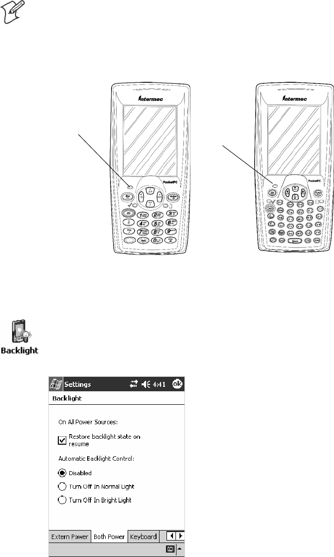
Ambient Light Sensor
Note: This information does not apply to the 730 Computer.
The ambient light sensor turns on the display lighting when conditions
warrant but automatically turns if off again as surrounding light increases.
This conserves your 700 Color battery power.
Ambient Light
Sensor Ambient Light
Sensor
This illustration shows the 700 Color Computer with a numeric keypad (left) and an alphanumeric
keypad (right).
To adjust the ambient light sensor, tap Start >Settings >theSystem tab >
the Backlight icon > the Both Power tab. Make your selections, then tap
ok to exit this applet.
Introduction—Chapter 1
3700 Series Color Mobile Computer User’s Manual
Audio System
The audio system consists of the speaker, internal microphone, and the
external headset jack.
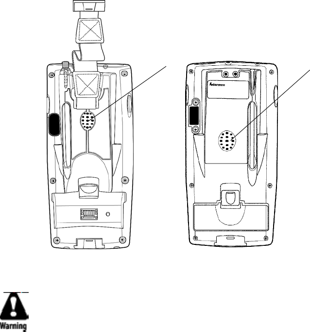
Speaker
A speaker capable of variable volume levels is located on the back of the
computer. This speaker has a transducer volume of 85 dB min at 10 CM
and a frequency range of 1–8 KHz.
Speaker Speaker
700 Color Computer 730 Computer
Warning: Do not place the speaker next to your ear when the speaker
volume is set to “Loud” (maximum), or you may damage your
hearing.
IntroductionChapter —1
4 700 Series Color Mobile Computer User’s Manual
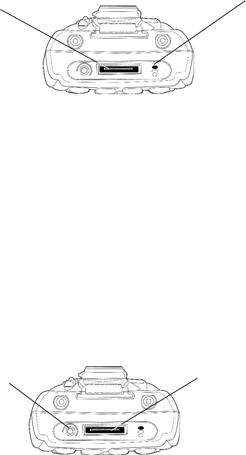
Microphone
The built-in microphone is located on the bottom of the unit next to the
Hirose docking connector.
Charging/Docking
connector Microphone
This is the bottom of the 700 Color Computer. Note that the keypad is to the bottom in this
illustration.
External Headset Jack
The external headset jack connects a mobile phone style headset to your
mobile computer for use in noisy environments. The jack is a 2.5 mm,
three-conductor jack, with autosensing of the headset jack insertion which
disables the internal speaker and microphone. The external headset jack is
located on the bottom of the mobile computer next to the Hirose docking
connector.
Charging/Docking
connector
Headset jack
This is the bottom of the 700 Color Computer. Note that the keypad is to the bottom in this
illustration.
Introduction—Chapter 1
5700 Series Color Mobile Computer User’s Manual
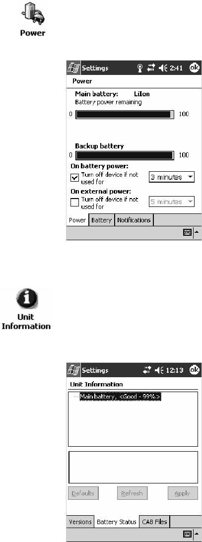
Battery
The 700 Color Computer comes with a 14.4 Watt-hour, 7.2V,
replaceable Lithium-Ion (LiIon) battery.
The 730 Computer comes with an 8.8 Watt-hour, 3.7V, replaceable LiIon
battery.
To view the status of this battery, tap Start >Settings >theSystem tab >
the Power icon > the Power tab to view the current status of both the
main battery and the backup battery. Tap ok to exit this information.
For Units With PSM Builds Older than 3.00
You can also view the battery status by accessing the Unit Information
control panel applet. Tap Start >Settings >theSystem tab>theUnit
Information icon > the Battery Status tab to view the current status. Tap
ok to exit this information.
IntroductionChapter —1
6 700 Series Color Mobile Computer User’s Manual
If your computer shuts down because of low battery conditions, your com-
puter does not operate. This is done to ensure that data is protected. Al-
though the battery does protect the data against loss for several hours, you
should connect your computer to a power source when you first detect a
low battery condition.
Your computer contains an internal super capacitor, a temporary power
storage device, that protects data for up to ten minutes. This is to give you
time to replace the main battery pack before that data is lost. Be sure to put
the computer in a suspend mode before doing so.
If you have at least one device in your 700 Color Computer (radio, scan-
ner, imager, or Ethernet), the battery power fail level is set so that after the
system shuts down in a low battery condition, there is still sufficient charge
to allow the unit to remain configured, keep proper time, and maintain
DRAM (Dynamic Random Access Memory) for at least 23 to 32 hours at
room temperature if the main battery remains in the mobile computer.
The configuration and time are lost if:
SThe battery discharges beyond this level.
SThe battery is removed when the computer is not in suspend mode.
SA cold reset is performed on the computer.
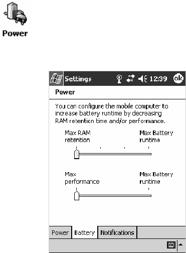
You can modify RAM maintenance in a limited way. On the 700 Color
Computer, tap Start >Settings >theSystem tab>thePower icon > the
Battery tab. Drag the slider bar to the right to change the suspend voltage
to favor suspend time over rundown time, then click ok to exit.
Introduction—Chapter 1
7700 Series Color Mobile Computer User’s Manual
Beeper
Note: Each time the 700 Color Computer is cold-booted, all default set-
tings are restored unless registry storage is enabled. See page 123 for infor-
mation about enabling the registry storage.
For information about setting volume levels for screen taps, ActiveSync
alert noises, etc., tap Start >Help >Pocket PC Basics
, then select
Notifications.
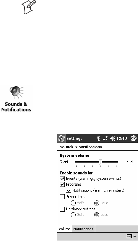
Enable the Beeper
To enable the beeper:
1Tap Start >Settings >thePersonal tab > Sounds & Notifications >the
Volume tab.
2Drag the System volume slider bar to the right of the “Silent” position.
3Tap ok to exit this applet.
IntroductionChapter —1
8 700 Series Color Mobile Computer User’s Manual
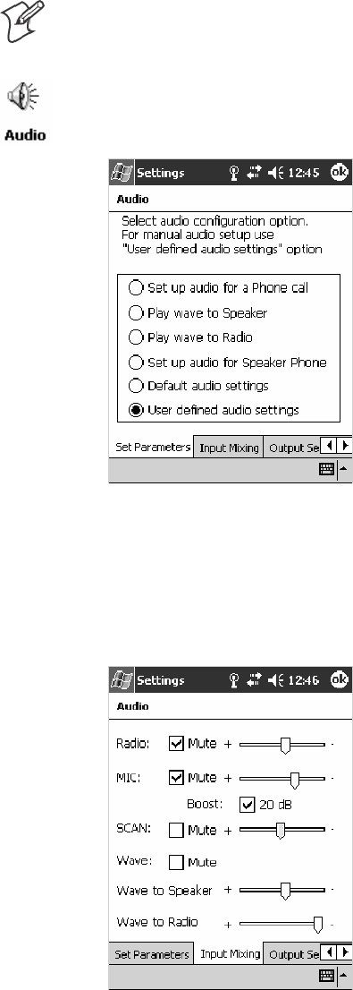
Disable the Scanner Mute
Note: This information does not apply to the 730 Computer.
Todisablethemutefeatureonthescanner.
1Tap Start >Settings >theSystem tab>theAudio icon, then select
User defined audio settings.
2Tap the Input Mixing tab, then clear the SCAN Mute box.
3Drag its slider bar (note the greyed slider bar) to the appropriate level of
loudest, with the left side being the most loud and the right side being
the most quiet. Tap ok to exit this applet.
Introduction—Chapter 1
9700 Series Color Mobile Computer User’s Manual
Select a Beeper Volume
Note: The 730 Computer does not support the laser scanner.
To determine your PSM Build version, tap Start >Programs >File Ex-
plorer >theFlash File Store folder > the PSMinfo text file.
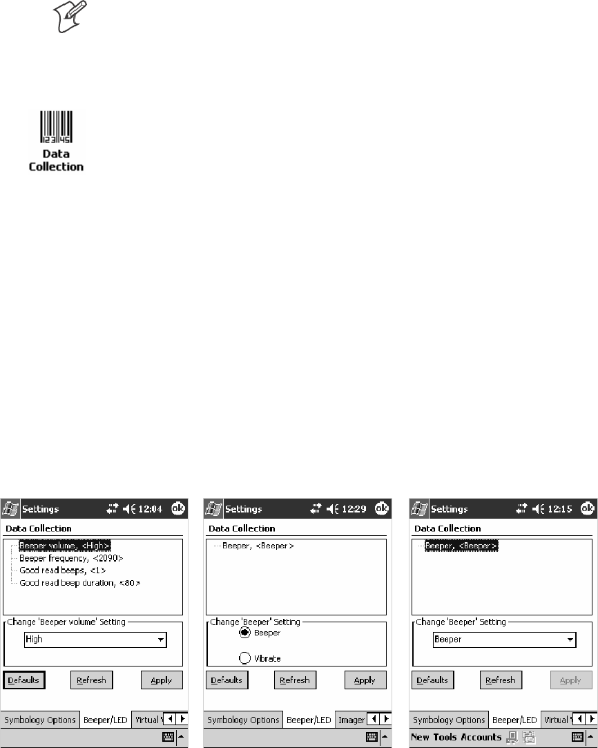
For Units With PSM Builds Older than 3.00
Do the following to select a beeper volume. 700 Color Computers built
with a laser scanner have three options: Off, High, or Medium. 700
Computers built with an imager have just two: Beeper or Vibrate. 730
Computers have just the Beeper option. See Appendix A, “Configurable
Settings,” for more information about the Beeper Volume or Beeper
option.
1Tap Start >Settings >theSystem tab>theData Collection icon to
access its control panel applet.
2Use the right and left arrows to scroll to the Beeper/LED tab, then tap
this tab.
3For units with laser scanners:
Tap Beeper Volume, select an option, then tap Apply to change the set-
ting.
For units with imagers:
Select either option, then tap Apply to change the setting. For 730 Com-
puters, the Vibrate option is not supported.
4Tap ok to confirm this change, then tap ok to exit the Data Collection
control panel applet.
700 Color with Imager Screen 730 Screen
700 Color with Laser Scanner
Screen
IntroductionChapter —1
10 700 Series Color Mobile Computer User’s Manual
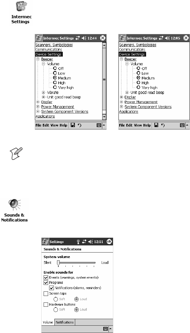
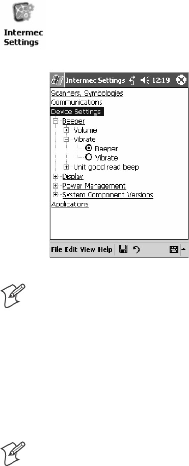
For Units With PSM Build 3.00 or Newer
To select a beeper volume for the 700 Color Computer, tap Start >Set-
tings >theSystem tab>theIntermec Settings icon. Tap the Device Set-
tings option, tap (+) to expand Beeper, then tap (+) to expand Volume.
Select an item, then close this option.
700 Color Screen 730 Screen
Note: Information about the settings you can configure with the Intermec
Settings control panel applet is described in the Intermec Computer Com-
mand Reference Manual (P/N: 073529). The online manual is available
from the Intermec web site at www.intermec.com.
Disable the Beeper
Do the following to disable the beeper:
1Tap Start >Settings >thePersonal tab > Sounds & Notification >the
Volume tab.
2Drag the System volume slider completely to the left to “Silent.”
3Tap ok to exit this applet.
Introduction—Chapter 1
11700 Series Color Mobile Computer User’s Manual
Keypad
Instructions for the keypad include the backlight and keypress sequences.
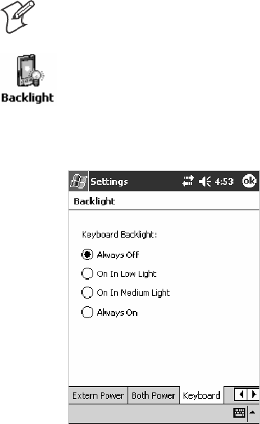
Backlight for Keypad
Note: This information does not apply to the 730 Computer.
You can configure your keypad to turn on a backlight to assist you when
you are working in low lighting. To adjust the backlight for the keypad,
tap Start >Settings >theSystem tab > Backlight. Use the left/right scroll
arrows to move to and tap the Keyboard tab. Make your selection, then
tap ok to exit this applet.

IntroductionChapter —1
12 700 Series Color Mobile Computer User’s Manual
Key Sequences
Use the following key sequences to enter characters into your 700 Color
Computer using either a numeric keypad or an alphanumeric keypad.
[Gold] or [Gold/White] Plane Keys
The [Gold] bplane key (numeric keypad) or the [Gold/White] cplane
key (alphanumeric keypad) provides you access to display controls, special
characters, and Pocket PC options.
Press the [Gold] bkey or the [Gold/White] ckey for each gold plane
key stroke you wish to make. For example to turn on the front light, press
andholdthe[Gold] bkey plus the 3key on the numeric keypad or
press and hold the [Gold/White] ckey plus the Ikey on the alphanu-
meric keypad. To turn the front light off, press the appropriate keys again.
Belowandonthenextpagearethekeysequences.
Numeric Keypad
The following table lists sequences that use the [Gold] bplane key. See
Chapter 2, “Windows Mobile 2003,” for information about the Pocket PC
applications.
Press the Keys To Do This
[Gold]
b3
Toggle the backlight on or off (also goes through backlight
power levels if held down)
[Gold]
ba
Access the Pocket PC Record application (see Note).
[Gold]
b4
Access the Pocket PC Calendar application (see Note).
[Gold]
b5
Access the Pocket PC Contacts application (see Note).
[Gold]
b6
Access the Pocket PC Tasks application (see Note).
[Gold]
b7
Move up one page.
[Gold]
b8
Enter an asterisk (*).
[Gold]
b9
Move down one page.
[Gold]
b0
Access the Pocket PC Start menu.
[Gold]
be
Enter an at symbol (@).
[Gold]
bK
Enter a backslash (/).
[Gold]
bE
Enter a minus sign (–).
[Gold]
bA
Enter a plus sign (+).
[Gold]
b→
Tab to the right.
[Gold]
b←
Tab to the left.
[Gold]
bU
Increase volume
[Gold]
bD
Decrease volume
Note: Pocket PC applications are accessible only if configured to do so in the App Launch
portion of the Utilities control panel applet. See page 358 for more information.

Introduction—Chapter 1
13700 Series Color Mobile Computer User’s Manual
Alphanumeric Keypad
Note: This information does not apply to the 730 Computer.
The following table lists sequences that use the [Gold/White] cplane
key. See Chapter 2, “Windows Mobile 2003,” for information about the
Pocket PC applications.
Press the Keys To Do This
[Gold/White]
cI
Toggle the backlight on or off (also goes through backlight
power levels if held down)
[Gold/White]
cA
Access the Pocket PC Record application (see Note).
[Gold/White]
cB
Access the Pocket PC Calendar application (see Note).
[Gold/White]
cC
Access the Pocket PC Contacts application (see Note).
[Gold/White]
cD
Access the Pocket PC Tasks application (see Note).
[Gold/White]
cJ
Move up one page.
[Gold/White]
cG
Enter an asterisk (*).
[Gold/White]
cP
Move down one page.
[Gold/White]
cE
Access the Pocket PC Start menu.
[Gold/White]
cK
Enter an at symbol (@).
[Gold/White]
cH
Enter a backslash (/).
[Gold/White]
cL
Enter a minus sign (–).
[Gold/White]
cR
Enter a plus sign (+).
[Gold/White]
cl
Tab to the right.
[Gold/White]
cj
Tab to the left.
[Gold/White]
ck
Increase volume
[Gold/White]
cm
Decrease volume
Note: Pocket PC applications are accessible only if configured to do so in the App Launch
portion of the Utilities control panel applet. See page 358 for more information.

IntroductionChapter —1
14 700 Series Color Mobile Computer User’s Manual
Alpha (Blue) Plane Keys
The alphabet can be entered with either the numeric keypad or the alpha-
numeric keypad. Below and on the next page are the key sequences.
Numeric Keypad
When you press F, the Scanning/Alpha LED (C)shows‘red’for
the Alpha mode. The keypad stays in Alpha mode until you press F.
To type a lowercase ‘c,’ press F222(the [2] key three
times). To type a letter on the same key as the last letter entered, wait two
seconds, then enter the correct series of keystrokes to create the next letter.
WhileyouareintheAlphamodeandyoupress1to initiate the CAPS
mode, you will render a CAPS LOCK until you press 1again. Once
you are in CAPS mode, you stay in CAPS until it is pressed again.
Press 0to enter a space.
To Enter Press the Keys To Enter Press the Keys
aF2 AF12
bF22 BF122
cF222 CF1222
dF3 DF13
eF33 EF133
fF333 FF1333
gF4 GF14
hF44 HF144
iF444 IF1444
jF5 JF15
kF55 KF155
lF555 LF1555
mF6 MF16
nF66 NF166
oF666 OF1666
pF7 PF17
qF77 QF177
rF777 RF1777
sF7777 SF17777
tF8 TF18
uF88 UF188
vF888 VF1888
wF9 WF19
xF99 XF199
yF999 YF1999
zF9999 ZF19999

Introduction—Chapter 1
15700 Series Color Mobile Computer User’s Manual
Alphanumeric Keypad
When you press d, the Scanning/Alpha LED (C) lights ‘red’ to indi-
cate Alpha mode. The keypad stays in the Alpha mode until you press d
again.
If you want to type a lowercase ‘c,’ press dC. If you want an uppercase
“C,” press and hold the gkey, then press C.
Press bto enter a space.
To Enter Press the Keys To Enter Press the Keys
a
dA
A
dgA
b
dB
B
dgB
c
dC
C
dgC
d
dD
D
dgD
e
dE
E
dgE
f
dF
F
dgF
g
dG
G
dgG
h
dH
H
dgH
i
dI
I
dgI
j
dJ
J
dgJ
k
dK
K
dgK
l
dL
L
dgL
m
dM
M
dgM
n
dN
N
dgN
o
dO
O
dgO
p
dP
P
dgP
q
dQ
Q
dgQ
r
dR
R
dgR
s
dS
S
dgS
t
dT
T
dgT
u
dU
U
dgU
v
dV
V
dgV
w
dW
W
dgW
x
dX
X
dgX
y
dY
Y
dgY
z
dZ
Z
dgZ
IntroductionChapter —1
16 700 Series Color Mobile Computer User’s Manual
Modem Support
The 700 ColorComputer has the following modem options:
SModem dock that provides charging and includes a built-in modem and
a serial port between which an application can switch.
SSnap-on modem, a stand-alone product, that attaches to the bottom of
your 700 Color Computer. Note that you cannot place this modem in a
dock, printer, or other devices. Contact your Intermec representative for
more information.
PSM Build Version
The Persistent Storage Manager (PSM) is an area of storage which is em-
bedded in a section of the system’s FLASH memory. This storage area is
not erased during a cold-boot. It may, however, be erased during the re-
flashing process. In addition to storing applications and data files, you do
have the option to store a persistent registry to the PSM region.
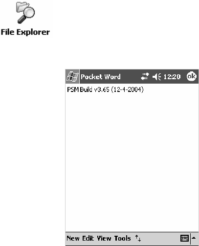
To determine what PSM Build is on your 700 Color Computer, tap Start
>Programs >File Explorer. Access the Flash File Store folder from the
My Device root directory, then tap the PSMinfo textfile.Takenoteof
your information, then tap ok to exit.
Introduction—Chapter 1
17700 Series Color Mobile Computer User’s Manual
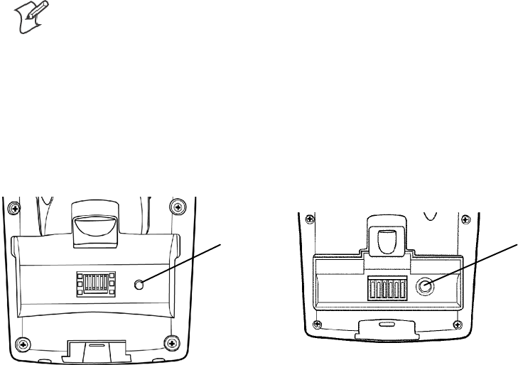
Resetting Your 700 Color Computer
In some cases where the 700 Color Computer completely stops respond-
ing, it may be necessary to perform a cold reset. Because cold resetting may
result in data loss, it is not recommended unless all other recovery methods
have failed.
Note: Cold resetting deletes all programs and data stored in RAM includ-
ing the Object Store. Make sure data is backed up to your host computer
or a storage card before performing a cold reset.
1Release the lower clip of the hand strap.
2Remove the battery pack.
3Press the Reset button.
4Reinstall the battery pack.
Reset button Reset button
700 Color Computer 730 Computer
This illustration shows the back of the 700 Color Computer on the left and of the 730 Computer on the right.
IntroductionChapter —1
18 700 Series Color Mobile Computer User’s Manual
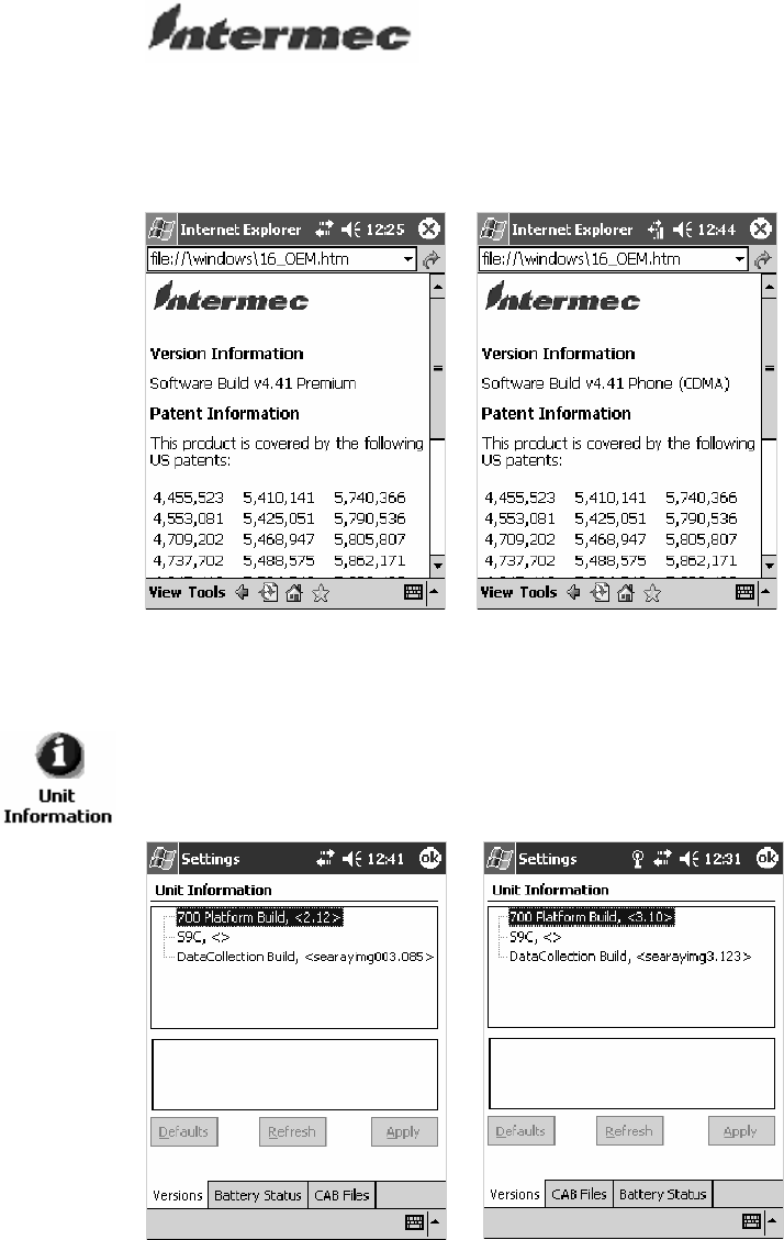
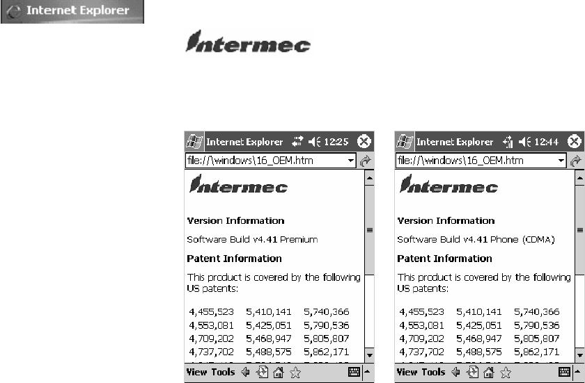
Software Build Version
To check to see if your 700 Color Computer has the latest software build,
select Start >Internet Explorer >theIntermec logo.
The latest software build version is displayed beneath the Version
Information title. This information would be useful should you need
assistance.
730, 740, 750, 760 Units 761 Units with CDMA
For Units With PSM Builds Older than 3.00
You can also view the latest software build by accessing the Unit
Information control panel applet. Select Start >Settings >theSystem tab
>theUnit Information icon > the Versions tab to view the current build.
700 Color Screen 730 Screen
Introduction—Chapter 1
19700 Series Color Mobile Computer User’s Manual
Storage Media
Note: MultiMediaCards (MMCs) are not supported in 700 Color Com-
puters.
The 700 Color Computer supports both CompactFlash and Secure Digital
storage cards. To access either card slot, locate the access door at the top of
the 700 Color Computer, remove its two screws, then remove the door.
See the 700 Color with Windows Mobile 2003 Quick Start Guide (P/N:
962-054-069) for more information.
The 730 Computer only supports the Secure Digital storage card. The
CompactFlash card slot is embedded in the 730 Computer and cannot be
removed. To access the Secure Digital card slot, locate the access door at
the top of the 730 Computer, remove its screws, then remove the door.
See the Model 730 Mobile Computer Quick Start Guide (P/N:
962-054-068) for more information.
CompactFlash Cards
On 700 Color Computers, the CompactFlash card slot accepts either a
storage card or the 802.11b or 802.11b/g radio, which is factory-installed
and cannot be removed. The 730 Computer does not support Compact-
Flash storage cards.
Secure Digital Cards
The Secure Digital card slot accepts storage cards only.
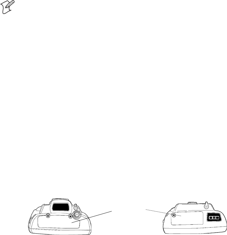
Storage Media
Access Door
700 Color Computer 730 Computer
This illustration shows the top of the 700 Color Computer on the left and of the 730 Computer on
the right. Note that the keypad is to the bottom.
IntroductionChapter —1
20 700 Series Color Mobile Computer User’s Manual
Vibrator
Note: This information does not apply to the 730 Computer.
Ifyour700ColorComputerisbuiltwithanimagerorscannerandthe
vibrator is disabled, do the following instructions to enable the vibrator. If
you are not able to enable the vibrator, then contact Customer Support.
For information about setting volume levels for screen taps, ActiveSync
alert noises, etc., tap Start
>
Help >Pocket PC Basics
, then select
Notifications.
See Chapter 7, “Programming,” to see how to programmatically control the
vibrator. See Appendix A, “Configurable Settings,” for more information
about the Beeper Volume option.
Note: Each time the 700 Color Computer is cold-booted, all default set-
tings are restored.
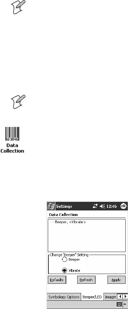
For Units With PSM Builds Older than 3.00
1Tap Start >Settings >theSystem tab > Data Collection to access its
control panel applet.
2Use the right and left arrows to scroll to the Beeper/LED tab, then tap
this tab.
3Tap Beeper, select the “Vibrate” option, then tap Apply.
4Tap ok to confirm this change, then tap ok to exit the Data Collection
control panel applet.
Introduction—Chapter 1
21700 Series Color Mobile Computer User’s Manual
For Units With PSM Build 3.00 or Newer
Do the following to enable the vibrator for the 700 Color Computer. Tap
Start >Settings >theSystem tab>theIntermec Settings icon. Tap the
Device Settings option, tap (+) to expand Beeper, then tap (+) to expand
Vibrate. Select an item, then close this option.
Note: Information about the settings you can configure with the Intermec
Settings control panel applet is described in the Intermec Computer Com-
mand Reference Manual. The online manual is available from the Intermec
web site at www.intermec.com
Wireless Network Support
Radios are installed at the factory and cannot be installed by a user. The
700 Color Computer must be serviced to install or replace radios. Contact
your Intermec representative for more information. See Chapter 4, “Net-
work Support” for information about supported radios.
Note: Changes or modifications not expressly approved by Intermec
Technologies Corporation could void the user’s authority to operate the
equipment.

IntroductionChapter —1
22 700 Series Color Mobile Computer User’s Manual
Accessories
The following accessories are available for the 700 Color Computer. Note
that this is not a complete list. Contact your Intermec representative for in-
formation about these and other accessories that are not in this list.
Accessory Descriptions
Intermec
Part Number 700 Color 730 Computer
Single Dock Charger with Ethernet and Auxiliary Battery Charger 225-681-001 X **
Single Dock Charger with USB and Ethernet 225-683-001 XX**
Quad Battery Charger 852-060-001
852-054-001
X
X
Single Battery Charger 852-060-002 X
Multidock — Charge Only (holds four 700 Computers) 225-682-004 X X
Multidock Charging with Ethernet support (holds four units) 225-682-003 X
Modem Dock 225-683-002 X X
Vehicle Dock 225-685-001 X X
Vehicle Cradle 225-680-101 X X
Snap-On Modem 225-687-001 X
Long Range Tethered Scanning Adapter (3.3v to 5v) 225-686-002 X
DEX Adapter 225-683-001 X
Standard Scan Handle Option 714-525-001
714-502-001
X
X
Dockable Scan Handle 714-525-002 X
Belt Clip 805-612-001 X X
** No Ethernet Support
What’s New
These changes have occurred since the last release of this manual, to in-
cludesoftwarechangesfromsoftwareversion4.0:
SAdded information about resetting the 700 Color Computer in this
chapter.
SRevised information about using Sprint Watcher and a Phone applica-
tion for 741, 751, or 761 Computers with CDMA or GSM radios in
Chapter 4, “Network Support.”
SUpdated information about the Profile Wizard in Appendix A, “Confi-
gurable Settings.”
SUpdated the manual to include 741, 751, and 761 Computers and the
MC46 Radio.
23700 Series Color Mobile Computer User’s Manual
Windows Mobile 2003
2
This chapter introduces Microsoft Windows Mobile 2003 for Pocket PC.
While using your 700 Color Computer, keep these key points in mind:
STap Start on the navigation bar, located at the top of the screen, to
quickly move to programs, files, and settings. Use the command bar at
the bottom of the screen to perform tasks in programs. The command
bar includes menus, buttons, and the onscreen keyboard.
STap and hold an item to see a pop-up menu containing a list of actions
you can perform. Pop-up menus give you quick and easy access to the
most common actions.
Note: “700 Color” pertains to 740, 741, 750, 751, 760, and 761 Com-
puters unless otherwise noted.
Below is a list of Windows Mobile 2003 components described in this
chapter. Tap Start >Help on your 700 Color Computer to find additional
information on Windows Mobile components.
Windows Mobile 2003 Components
Microsoft ActiveSync Client (page 44)
Microsoft Pocket Outlook (page 46)
Pocket Word (page 78)
Pocket Excel (page 82)
MSN Messenger (page 84)
Windows Media Player for Pocket PC (page 89)
Microsoft Reader (page 90)
Pocket Internet Explorer (page 94)
Windows Mobile 2003Chapter —2
24 700 Series Color Mobile Computer User’s Manual
Software Builds
Do the following to determine which Intermec build of Windows Mobile
2003 is on your unit.
1Select Start >Internet Explorer >theIntermec logo.
2Note the “Software Build” information displayed beneath the Version
Information title.
730, 740, 750, 760 Units 761 Units with CDMA
3Tap the Close icon in the top right corner to exit the Internet Explorer.

Windows Mobile 2003—Chapter 2
25700 Series Color Mobile Computer User’s Manual
Where to Find Information
This chapter describes your 700 Color Computer hardware, provides an
overview of the programs on your 700 Color Computer, and explains how
to connect your 700 Color Computer to a desktop, a network, or the In-
ternet. For instructions on setting up your 700 Color Computer and
installing ActiveSync, see the Quick Start Guide. The following is a guide
to more information to assist you use your 700 Color Computer.
For information on: See this source:
Programs on your mobile computer. This chapter and mobile computer Help. To view Help,
tap Start >Help.
Additional programs that can be installed on the mobile
computer.
The Windows Mobile Companion CD.
Connecting to and synchronizing with a desktop. The Quick Start Guide or AutoSync Help on your desk-
top. To view Help, click Help >Microsoft ActiveSync
Help.
Last-minute updates and detailed technical information. The Read Me files, located in the Microsoft ActiveSync
folder on the desktop and on the Windows Mobile Com-
panion CD.
Up-to-date information on your Windows Mobile. http://www.microsoft.com/windowsmobile/resources/
communities/default.mspx
Windows Mobile and many of the technologies supported by the 700 Col-
or Computer are not from Intermec Technologies. Many of the utilities
and features on a Windows Mobile device come directly from Microsoft
without any modification from Intermec Technologies. There may be cer-
tain Microsoft-specific issues that Intermec Technologies would not be
able to support, so contact our front-line support personnel to determine
the best source of assistance.
Use these URLs for additional information about Microsoft Windows
Mobile (Pocket PC):
Shttp://msdn.microsoft.com/support/
Shttp://support.microsoft.com/
Snews://news.microsoft.com (a free support option)
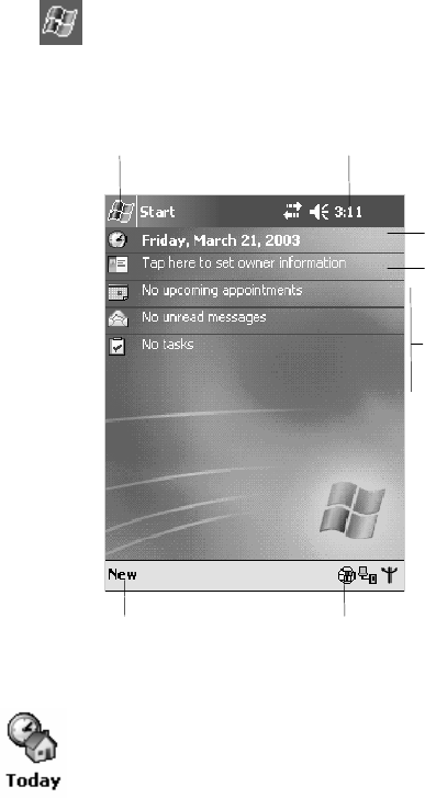
Windows Mobile 2003Chapter —2
26 700 Series Color Mobile Computer User’s Manual
Basic Skills
Learning to use your 700 Color Computer is easy. This section describes
the basic concepts of using and customizing your 700 Color Computer.
Today Screen
When you turn on your 700 Color Computer for the first time each day
(or after four hours of inactivity),youseetheToday screen. You can also
displayitbytappingtheStart flag (shown left) and then Today.Onthe
Today screen, you can see important information for the day.
Taptocreatea
new item.
Your day at a glance. Tap
to open the associated
program.
Tap to disconnect from ActiveSync.
Tap to change owner
information.
Tap to change date and time.
Tap and hold to change time format.
Tap to start a program.
To customize what is displayed on the Today screen, including the back-
ground image, tap Start >Settings >thePersonal tab > Today.
Status icons display information such as low batteries or when the 700
Color Computer is connected to a desktop or to the Internet. You can tap
an icon to open the associated setting or program.
Windows Mobile 2003—Chapter 2
27700 Series Color Mobile Computer User’s Manual
Programs
You can switch from one program to another by selecting it from the Start
menu. (You can customize which programs you see on this menu. For
information, see “Adjusting Settings” on page 41.) To access some
programs, tap Start >Programs, and then the program name.
You can also switch to some programs by pressing a program button. Your
700 Color Computer has one or more program buttons located on the
front or side of the computer. The icons on the buttons identify the pro-
grams to which they switch.
Note: Some programs have abbreviated labels for check boxes and drop-
down menus. To see the full spelling of an abbreviated label, tap and hold
the stylus on the label. Drag the stylus off the label so that the command is
not carried out.
The following is a partial list of programs that are on your 700 Color
Computer. Look on the Windows Mobile Companion CD for additional
programs that you can install onto your 700 Color Computer.
Synchronize information between your 700 Color Computer and desktop.
Keep track of your appointments and create meeting requests.
Keep track of your friends and colleagues.
Send and receive e-mail messages.
Browse Web and WAP (Wireless Application Protocol) sites, and down-
load new programs and files from the Internet.
Create handwritten or typed notes, drawings, and recordings.
Keep track of your tasks.
Play digital audio and video files that are stored on your 700 Series Com-
puteroronanetwork.
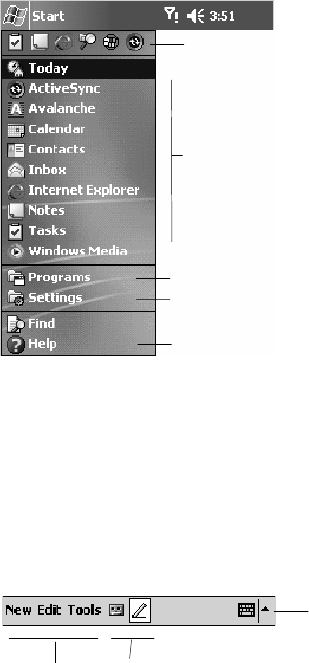
Windows Mobile 2003Chapter —2
28 700 Series Color Mobile Computer User’s Manual
Navigation Bar and Command Bar
The navigation bar is located at the top of the screen. It displays the active
program and current time, and allows you to switch to programs and close
screens.
Taptoswitchtoaprogram.
Tap to see more programs.
Taptoswitchtoaprogram
that you recently used.
Tap to change device
settings.
Tap to see a Help topic
for the current screen.
Use the command bar at the bottom of the screen to perform tasks in pro-
grams. The command bar includes menu names, buttons, and the Input
Panel button. To create a new item in the current program, tap New.To
see the name of a button, tap and hold the stylus on the button. Drag the
stylus off the button so that the command is not carried out.
Taptoselect
menu commands.
Tap to display the input
panel.
Taptoselect
button commands.
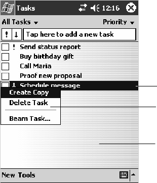
Windows Mobile 2003—Chapter 2
29700 Series Color Mobile Computer User’s Manual
Pop-up Menus
Use pop-up menus to quickly perform an action on an item. For example,
you can use a pop-up menu to delete or make a copy of an item. To access
a pop-up menu, tap and hold the item on which you want to perform the
action. When the menu appears, tap the action you want to perform, or
tap anywhere outside the menu to close the menu without performing the
action.
Tap and hold to display the
pop-up menu.
Lift the stylus and tap the action
you want.
Tap outside the menu to
close it without performing
an action.
Notifications
When you have something to do, your device notifies you in a variety of
ways. For example, if you have set up an appointment in Calendar, an e-
mail message arrives, or a friend sends you an instant message, you are no-
tified in any of the following ways:
SA message box appears on the screen.
SA sound, which you can specify, is played.
SA light flashes on your 700 Color Computer.
SThe700ColorComputervibrates.
You can choose the notification types.
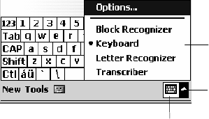
Windows Mobile 2003Chapter —2
30 700 Series Color Mobile Computer User’s Manual
Entering Information
You can enter information on your 700 Color Computer in several ways,
depending on the type of device you have and the program you are using:
SSynchronizing
Using Microsoft ActiveSync, synchronize or copy information between
your desktop and 700 Color Computer. For more information on Acti-
veSync, see ActiveSync Help on your desktop.
STyping
Using the input panel, enter typed text into the 700 Color Computer.
You can do this by tapping keys on the onscreen keyboard or by using
handwriting recognition software.
SWriting
Using the stylus, write directly on the screen.
SDrawing
Using the stylus, draw directly on the screen.
SRecording
Create a stand-alone recording or embed a recording into a document or
note.
Use the input panel to enter information in any program on your 700
Color Computer. You can either type using the onscreen keyboard or
write using Block Recognizer,Letter Recognizer,orTranscriber.Ineither
case, the characters appear as typed text on the screen.
To show or hide the input panel, tap the Input Panel button. Tap the ar-
row next to the Input Panel button to see your choices.
Tap to see your choices.
Input Panel button.
Select an input method.
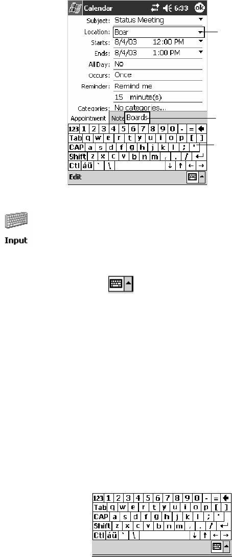
Windows Mobile 2003—Chapter 2
31700 Series Color Mobile Computer User’s Manual
When you use the input panel, your 700 Color Computer anticipates the
word you are typing or writing and displays it above the input panel.
When you tap the displayed word, it is inserted into your text at the
insertion point. The more you use your 700 Color Computer, the more
words it learns to anticipate.
Tap a text box to display
the currently selected
input panel (in this case,
Keyboard).
To enter characters, tap
them on the onscreen
keyboard.
Tap to insert anticipated
word.
To change word suggestion options, such as the number of words sug-
gested at one time, tap Start >Settings >thePersonal tab > Input >the
Word Completion tab.
Typing With the Onscreen Keyboard
Tap the arrow, then tap Keyboard. On the soft keyboard that is dis-
played, tap the keys with your stylus.
STo type lowercase letters, tap the keys with the stylus.
STo type a single uppercase letter or symbol, tap the Shift key. To tap
multiple uppercase letters or symbols, tap the CAP key.
STo convert a letter to uppercase, tap and hold the stylus on the letter
and drag up.
STo add a space, drag the stylus to the right across at least two keys.
STo backspace one character, drag the stylus to the left across at least
two keys.
STo insert a carriage return, tap and hold the stylus anywhere on the
keyboard and drag down.
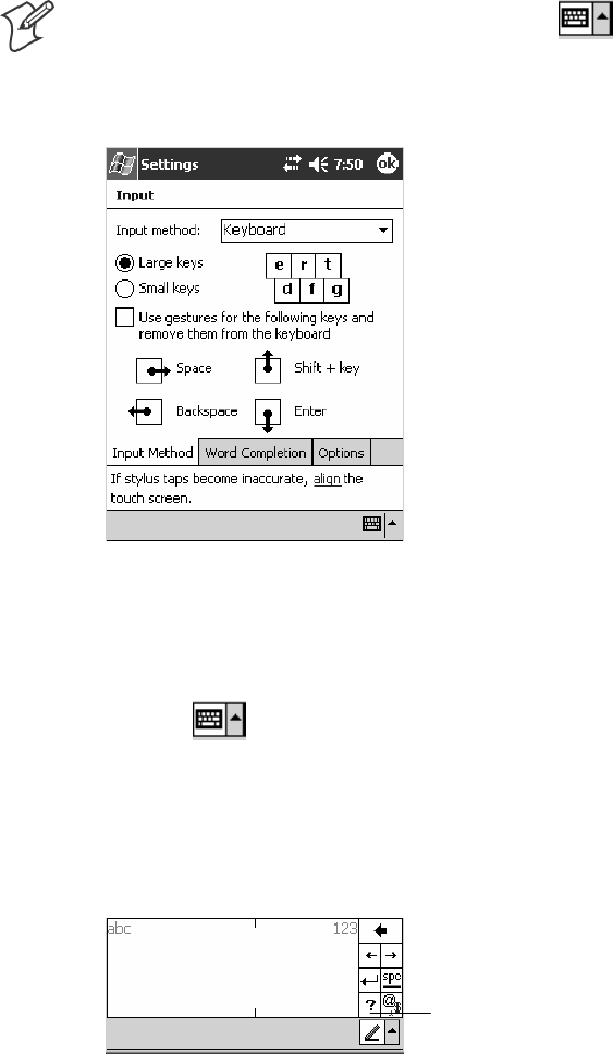
Windows Mobile 2003Chapter —2
32 700 Series Color Mobile Computer User’s Manual
Note: If you want to use larger keys, tap the arrow, tap Options,
select “Keyboard” from the Input method drop-down list, then select
Large keys.
Using Block Recognizer
Character recognition software gives you a fast and easy method for enter-
ing information in any program on your 700 Color Computer. Letters,
numbers, and punctuation you write are translated into typed text.
Tap the arrow, then tap Block Recognizer. Write a letter in the box.
When you write a letter, it is converted to typed text that appears on the
screen.
For specific instructions on using Block Recognizer, with Block Recogniz-
er open, tap the question mark next to the writing area.
Tap for assistance.
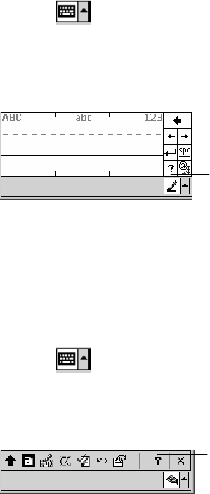
Windows Mobile 2003—Chapter 2
33700 Series Color Mobile Computer User’s Manual
Using Letter Recognizer
With Letter Recognizer, you can write letters using the stylus just as you
would on paper.
Tap the arrow, then tap Letter Recognizer. Write a letter in the box.
When you write a letter, it is converted to typed text that appears on the
screen. For specific instructions on using Letter Recognizer, with Letter
Recognizer open, tap the question mark next to the writing area.
Tap for assistance.
Using Transcriber
With Transcriber, you can write anywhere on the screen using the stylus
just as you would on paper. Unlike Letter Recognizer and Block Recogniz-
er, you can write a sentence or more of information. Then, pause and let
Transcriber change the written characters to typed characters.
Tap the arrow, then tap Transcriber. Write anywhere on the screen.
For specific instructions on using Transcriber, with Transcriber open, tap
the question mark in the lower, right-hand corner of the screen.
Tap for assistance.
Selecting Typed Text
Ifyouwanttoeditorformattypedtext,youmustselectitfirst.
SDrag the stylus across the text you want to select.
You can cut, copy, and paste text by tapping and holding the selected
words and then tapping an editing command on the pop-up menu, or by
tapping the command on the Edit menu.

Windows Mobile 2003Chapter —2
34 700 Series Color Mobile Computer User’s Manual
Writing on the Screen
In any program that accepts writing, such as the Notes program, and in
the Notes tab in Calendar, Contacts, and Tasks, you can use your stylus to
write directly on the screen. Write the way you do on paper. You can edit
andformatwhatyouhavewrittenandconverttheinformationtotextata
later time.
STap the Pen button to switch to writing mode. This action displays
lines on the screen to help you write.
Tap to use your stylus like a pen.
Note: Some programs that accept writing may not have the Pen button.
Seethedocumentationforthatprogramtofindouthowtoswitchtowrit-
ing mode.
Selecting the Writing
Ifyouwanttoeditorformatwriting,youmustselectitfirst.
1Tap and hold the stylus next to the text you want to select until the in-
sertion point appears.
2Without lifting, drag the stylus across the text you want to select.
If you accidentally write on the screen, tap Tools >Undo and try again.
You can also select text by tapping the Pen button to deselect it and then
dragging the stylus across the screen.
You can cut, copy, and paste written text in the same way you work with
typed text: tap and hold the selected words and then tap an editing com-
mand on the pop-up menu, or tap the command on the Edit menu.
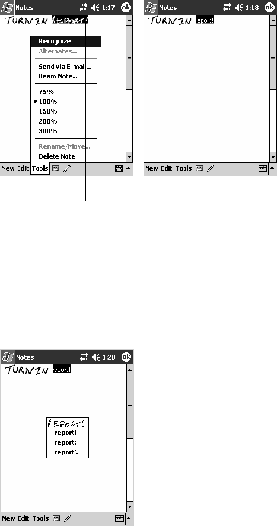
Windows Mobile 2003—Chapter 2
35700 Series Color Mobile Computer User’s Manual
Converting Writing to Text
You can convert words you write in print or cursive to text by tapping
Tools >Recognize. If a word is not recognized, it stays in its written form.
If you want to convert only certain words, tap Pen to disable the writing
function, tap twice over the word or phrase to highlight, then tap Tools >
Recognize.
Tap to disable the pen function.
Select the text you want to
convert and tap Recognize
on the pop-up menu.
The writing is turned
into text.
If the conversion is incorrect, you can choose different words from a list of
alternates or return to the original writing. To do so, tap and hold the
incorrect word (tap one word at a time). On the pop-up menu, tap
Alternates. Tap the word you want to use from the menu with a list of
alternate words, or tap the writing at the top of the menu to return to the
original writing.
Taptoreturntoyour
original writing.
Or, tap the word you
want to use.
Windows Mobile 2003Chapter —2
36 700 Series Color Mobile Computer User’s Manual
Tips for getting good recognition:
SWrite neatly.
SWrite on the lines and draw descenders below the line. Write the cross
of the “t” and apostrophes below the top line so they are not confused
with the word above. Write periods and commas above the baseline.
SFor better recognition, try increasing the zoom level to 300% by using
the Tools menu. Recognition does not work well below a 150% zoom
level.
SWrite the letters of a word closely and leave big gaps between words so
that the 700 Color Computer can easily tell where words begin and end.
SHyphenated words, foreign words that use special characters such as ac-
cents, and some punctuation cannot be converted.
SIf you add writing to a word to change it (such as changing a “3” to an
“8”) after you attempt to recognize the word, the writing you add is not
included if you attempt to recognize the writing again.
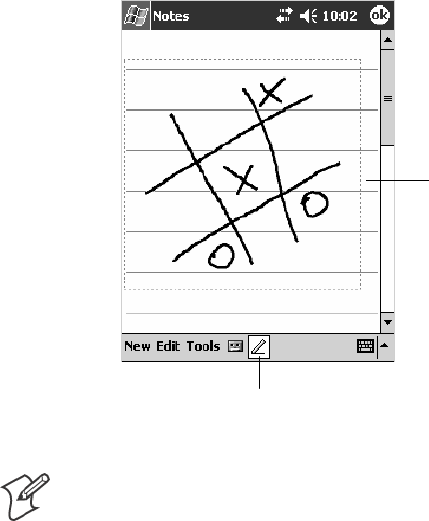
Windows Mobile 2003—Chapter 2
37700 Series Color Mobile Computer User’s Manual
Drawing on the Screen
You can draw on the screen in the same way that you write on the screen.
The difference between writing and drawing on the screen is how you se-
lect items and how they are edited. For example, you can resize selected
drawings, while you cannot resize writing.
Creating a Drawing
SCross three ruled lines on your first stroke. A drawing box appears. Sub-
sequent strokes in or touching the drawing box become part of the dra-
wing. Drawings that do not cross three ruled lines are treated as writing.
The drawing box indicates
the boundaries of the
drawing.
Pen button.
Note: You may want to change the zoom level so that you can more easily
work on or view your drawing. Tap Tools and then a zoom level.
Selecting a Drawing
Ifyouwanttoeditorformatadrawing,youmustselectitfirst.
STap and hold the stylus on the drawing until the selection handle ap-
pears. To select multiple drawings, deselect the Pen button and then
drag to select the drawings you want.
You can cut, copy, and paste selected drawings by tapping and holding the
selected drawing and then tapping an editing command on the pop-up
menu, or by tapping the command on the Edit menu. To resize a drawing,
make sure the Pen button is not selected, and drag a selection handle.
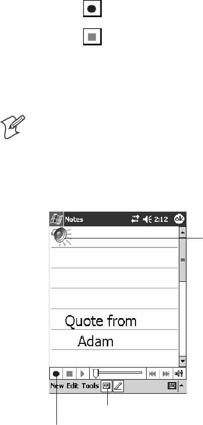
Windows Mobile 2003Chapter —2
38 700 Series Color Mobile Computer User’s Manual
Recording a Message
In any program where you can write or draw on the screen, you can also
quickly capture thoughts, reminders, and phone numbers by recording a
message.
In the Inbox program, you can add a recording to an e-mail message. In
Calendar, Tasks, and Contacts, you can include a recording in the Notes
tab. In the Notes program, you can create a stand-alone recording or add a
recording to an open note.
Creating a Recording
1Hold the 700 Color Computer’s microphone near your mouth or
source of sound.
2Tap and make your recording.
3Tap when finished. If you are recording in an open note, an icon
appears in the note. If you are creating a stand-alone recording, it ap-
pears in the note list.
4To play a recording, tap the recording icon in the open note or tap the
recording in the note list.
Note: To quickly create a recording, hold down the Record hardware but-
ton. When you hear the beep, begin your recording. Release the button
when you are finished. The new recording is stored in the open note or as
a stand-alone recording if no note is open.
To play a recording, tap it in the list or tap its icon in the note.
Indicates an em-
bedded recording.
Tap to begin recording.
Tap to show or hide the Recording toolbar.
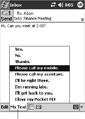
Windows Mobile 2003—Chapter 2
39700 Series Color Mobile Computer User’s Manual
Using My Text
When using Inbox or MSN Messenger, use My Text to quickly insert pre-
set or frequently used messages into the text entry area. To insert a mes-
sage, tap My Text and tap a message.
STo quickly add common messages, tap My Text and tap a desired mes-
sage.
STo edit a My Text message, tap Tools >Edit My Text Messages.Tap
the message you want to edit and enter new text at the bottom of the
screen.
Tap to select a prewritten message.
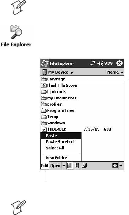
Windows Mobile 2003Chapter —2
40 700 Series Color Mobile Computer User’s Manual
Finding and Organizing Information
The Find feature on your 700 Color Computer helps you quickly locate
information.
Tap Start >Find. Enter the text you want to find, select a data type, and
then tap Go to initiate the search.
Note: To quickly find information that is taking up storage space on your
700 Color Computer, select Larger than 64 KB in Type.
You can also use the File Explorer to find files on your 700 Color Com-
puter and to organize these files into folders. Tap Start >Programs >File
Explorer.
Tap the folder name
to open it.
Tap New Folder to
create a new folder.
Note: You can move files in File Explorer by tapping and holding the item
you want to move, and then tapping Cut or Copy and Paste on the pop-
up menu.

Windows Mobile 2003—Chapter 2
41700 Series Color Mobile Computer User’s Manual
Customizing Your 700 Color Computer
You can customize your 700 Color Computer by adjusting settings and
installing additional software.
Adjusting Settings
You can adjust settings to suit the way you work. To see available options,
tap Start >Settings > either of the following tabs located at the bottom of
thescreen.Youmightwanttoadjustthefollowing:
Personal Tab
Menus:
To customize what appears on the Start menu, and to enable a pop-up
menu from the New button.
Owner Information:
Toenteryourcontactinformation.
Password:
To limit access to your 700 Color Computer.
Today:
To customize the look and information displayed on the Today screen.
System Tab
Clock:
To change the time or to set alarms.
Power:
To maximize battery life.
Adding or Removing Programs
Programs added to your 700 Color Computer at the factory are stored in
ROM (Read Only Memory). You cannot remove this software, and you
cannot accidentally lose ROM contents. ROM programs can be updated
using special installation programs with a *.XIP extension. All other pro-
grams and data files added to your 700 Color Computer after factory
installation are stored in RAM (Random Access Memory).
You can install any program created for your 700 Color Computer, as long
as your 700 Color Computer has enough memory. The most popular
place to find software for your 700 Color Computer is on the Windows
Mobile Web site (http://www.microsoft.com/windowsmobile/resources/
communities/default.mspx).

Windows Mobile 2003Chapter —2
42 700 Series Color Mobile Computer User’s Manual
Adding Programs Using ActiveSync
Install the appropriate software for your 700 Color Computer on your
desktop before installing it on your 700 Color Computer.
1Determine your 700 Color Computer and processor type so that you
know which version of the software to install. Tap Start >Settings >the
System tab > About >theVersion tab, then make a note of the
information in Processor.
2Download the program to your desktop (or insert the CD or disk that
contains the program into your desktop). You may see a single *.XIP,
*.EXE, or *.ZIP file, a SETUP.EXE file, or several versions of files for
different 700 Color Computer types and processors. Be sure to select
the program designed for the Windows Mobile and your 700 Color
Computer processor type.
3Read any installation instructions, Read Me files, or documentation that
comes with the program. Many programs provide special installation
instructions.
4Connect your 700 Color Computer and desktop.
5Double-click the *.EXE file.
SIf the file is an installer, the installation wizard begins. Follow the di-
rections on the screen. Once the software is installed, the installer au-
tomatically transfers the software to your 700 Color Computer.
SIf the file is not an installer, an error message stating that the program
is valid but it is designed for a different type of computer is displayed.
Move this file to your 700 Color Computer. If you cannot find any
installation instructions for the program in the Read Me file or docu-
mentation, use ActiveSync Explore to copy the program file to the
Program Files folder on your 700 Color Computer. For more infor-
mation on copying files using ActiveSync, see ActiveSync Help.
Once installation is complete, tap Start >Programs, and then the program
icon to switch to it.
Adding a Program Directly from the Internet
1Determine your 700 Color Computer and processor type so that you
know which version of the software to install. Tap Start >Settings >the
System tab > About >theVersion tab, then make a note of the
information in Processor.
2Download the program to your 700 Color Computer straight from the
Internet using Pocket Internet Explorer. You may see a single *.XIP,
*.EXE, or *.ZIP file, a SETUP.EXE file, or several versions of files for
different 700 Color Computer types and processors. Be sure to select
the program designed for the Windows Mobile and your 700 Color
Computer processor type.
3Read program installation instructions, Read Me files, or other docu-
mentation. Many programs provide installation instructions.
4Tap the file, such as a *.XIP or *.EXE file to start the installation wi-
zard. Follow the directions on the screen.

Windows Mobile 2003—Chapter 2
43700 Series Color Mobile Computer User’s Manual
Adding a Program to the Start Menu
Tap Start >Settings >Menus >theStart Menu tab, and then the check
box for the program. If you do not see the program listed, you can either
useFileExploreronthe700ColorComputertomovetheprogramtothe
Start Menu folder, or use ActiveSync on the desktop to create a shortcut
to the program and place the shortcut in the Start Menu folder.
Using File Explorer on the 700 Color Computer
Tap Start >Programs >File Explorer, and locate the program (tap the
folder list, labeled My Documents by default, and then My Device to see a
list of all folders on the 700 Color Computer). Tap and hold the program
and tap Cut on the pop-up menu. Open the Start Menu folder located in
the Windows folder, tap and hold a blank area of the window, and tap
Paste on the pop-up menu. The program now appears on the Start menu.
For more information on using File Explorer, see “Finding and Organizing
Information” on page 40.
Using ActiveSync on the desktop
Use the Explorer in ActiveSync to explore your 700 Color Computer files
and locate the program. Right-click the program, and then click Create
Shortcut. Move the shortcut to the Start Menu folder in the Windows
folder. The shortcut now appears on the Start menu. For more informa-
tion, see ActiveSync Help.
Removing Programs
Tap Start >Settings >theSystem tab > Remove Programs.
If the program does not appear in the list of installed programs, use File
Explorer on your 700 Color Computer to locate the program, tap and
hold the program, and then tap Delete on the pop-up menu.

Windows Mobile 2003Chapter —2
44 700 Series Color Mobile Computer User’s Manual
Microsoft ActiveSync
Visit the following Microsoft Web site for the latest in updates, technical
information, and samples:
http://www.microsoft.com/windowsmobile/resources/communities/de-
fault.mspx
Using Microsoft ActiveSync, you can synchronize the information on your
desktop with the information on your 700 Color Computer. Synchroniza-
tion compares the data on your 700 Color Computer with your desktop
and updates both computers with the most recent information. For exam-
ple:
SKeep Pocket Outlook data up-to-date by synchronizing your 700 Color
Computer with Microsoft Outlook data on your desktop.
SSynchronize Microsoft Word and Microsoft Excel files between your
700 Color Computer and desktop. Your files are automatically con-
verted to the correct format
Note: By default, ActiveSync does not automatically synchronize all types
of information. Use ActiveSync options to turn synchronization on and off
for specific information types.
With ActiveSync, you can also:
SBack up and restore your 700 Color Computer data.
SCopy (rather than synchronize) files between your 700 Color Computer
and desktop.
SControl when synchronization occurs by selecting a synchronization
mode. For example, you can synchronize continually while connected to
your desktop or only when you choose the synchronize command.
SSelect which information types are synchronized and control how much
data is synchronized. For example, you can choose how many weeks of
past appointments you want synchronized.
Before you begin synchronization, install ActiveSync on your desktop from
the Windows Mobile Companion CD. For more information on installing
ActiveSync, see your Quick Start card. ActiveSync is already installed on
your 700 Color Computer.
After installation is complete, the ActiveSync Setup Wizard helps you con-
nectyour700ColorComputertoyourdesktop,setupapartnershipso
you can synchronize information between your 700 Color Computer and
your desktop, and customize your synchronization settings. Your first syn-
chronization process automatically begins when finished using the wizard.
After your first synchronization, look at Calendar, Contacts, and Tasks on
your 700 Color Computer. Notice that information you have stored in
Microsoft Outlook on your desktop was copied to your 700 Color Com-
puter, and you did not have to type a word. Disconnect the 700 Color
Computer from your computer and you are ready to go!
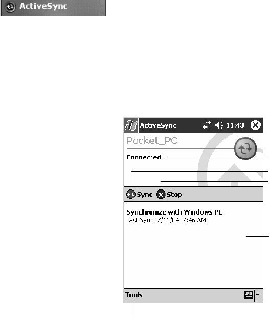
Windows Mobile 2003—Chapter 2
45700 Series Color Mobile Computer User’s Manual
Once you have set up ActiveSync and completed the first synchronization
process, you can initiate synchronization from your 700 Color Computer.
To switch to ActiveSync on your 700 Color Computer, tap Start >
ActiveSync. Note that if you have a wireless LAN card, you can
synchronize remotely from your 700 Color Computer.
For information about using ActiveSync on your desktop, start ActiveSync
on your desktop, and then see ActiveSync Help.
Tap to synchronize via IR or change
synchronization settings.
View connection status.
Tap to connect and synchronize.
Taptostopsynchronization.
View synchronization status.
For more information about ActiveSync on your 700 Color Computer,
switch to ActiveSync, then tap Start >Help.
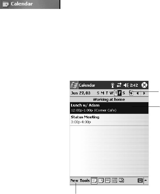
Windows Mobile 2003Chapter —2
46 700 Series Color Mobile Computer User’s Manual
Microsoft Pocket Outlook
Microsoft Pocket Outlook includes Calendar, Contacts, Tasks, Inbox, and
Notes. You can use these programs individually or together. For example,
youcanusee-mailaddressesstoredinContactstoaddresse-mailmessages
in Inbox.
Using ActiveSync, you can synchronize information in Microsoft Outlook
or Microsoft Exchange on your desktop with your 700 Color Computer.
You can also synchronize this information directly with a Microsoft Ex-
change server. Each time you synchronize, ActiveSync compares the
changes you made on your 700 Color Computer and desktop or server
and updates both computers with the latest information. For information
on using ActiveSync, see ActiveSync Help on the desktop.
You can switch to any program by tapping it on the Start menu.
Calendar: Scheduling Appointments and Meetings
To switch to Calendar on the 700 Color Computer, tap Start >Calendar.
Use Calendar to schedule appointments, including meetings and other
events. You can check your appointments in one of several views (Day,
Week, Month, Year, and Agenda) and set Calendar to remind you of ap-
pointments with a sound or other method.
Appointments for the day can display on the Today screen.
If you use Outlook on your desktop, you can synchronize appointments
between your device and desktop.
Tap to create a new appointment
TaptogotoToday
Tap to display or edit
the appointment details.
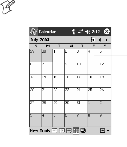
Windows Mobile 2003—Chapter 2
47700 Series Color Mobile Computer User’s Manual
Synchronizing Calendar
Calendar items stored on your device can be synchronized with calendar
items on your desktop or Microsoft Exchange Server. (Note that you can
only synchronize information directly with an Exchange Server if your
company is running Microsoft Mobile Information Server 2002 or later.)
Calendar synchronization is automatically selected in ActiveSync.
Calendar items entered on one computer are copied to the other during
synchronization. Handwritten notes and drawings are saved as metafiles
(pictures).
For more information on synchronization, see ActiveSync Help on the
desktop.
Why Use Categories in the Calendar?
Use categories to group related tasks, contacts, and appointments. Then,
use these groupings to quickly display only the information you want. For
example, you can easily share your device with another by assigning your
appointments to a category with a special project’s name. You can then use
this category to filter Calendar and only display appointments for that
project.
Note: In Month View, the day of an appointment assigned to the Holiday
category appears in red.
TaptoaccesstheMonthview
This day was assigned
the Holiday category.
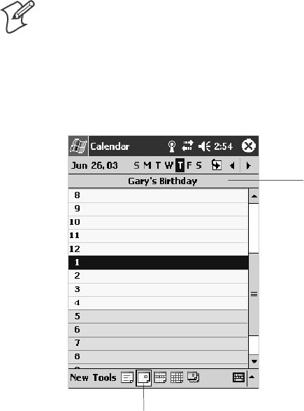
Windows Mobile 2003Chapter —2
48 700 Series Color Mobile Computer User’s Manual
What’s an All Day Event?
An appointment can either be a normal appointment or an all day event,
which lasts the full day or spans many days. Examples include a trade
show, a vacation, or a seminar. You can also use all day events to schedule
an annual event, such as a birthday or anniversary. In this case, change the
Status box to Free (you may need to scroll to see it) so that it does not
show time as busy in your calendar. All day events do not occupy blocks of
time in Calendar; they appear in banners at the top of the calendar.
Note: You cannot modify or create all day events with attendees on the
device. If you create all day events with attendees on your desktop, use Ac-
tiveSync to copy such events to the device. Then, view them in Calendar.
For more information on copying files, see ActiveSync Help.Tousethe
device to schedule an appointment with attendees lasting all day, set type
to “Normal,” then adjust the date and time appropriately.
Tap to access the Day view
This describes the all
day event.
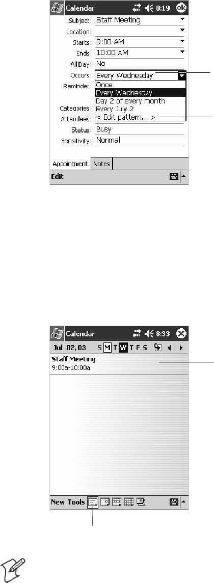
Windows Mobile 2003—Chapter 2
49700 Series Color Mobile Computer User’s Manual
What’s a Recurrence Pattern?
If you have an appointment or task that you do on a regular basis, such as
a weekly team meeting or a monthly status report, enter the item once and
set a recurrence pattern for it. If the default patterns in the list are not
what you need, you can create your own pattern using the wizard.
Select your recurrence
pattern from this drop-
down list.
Select <Edit pattern...>
to access the wizard
with which to custom-
ize your recurrence.
Viewing Appointments
You can view appointments in one of several views (Agenda, Day, Week,
and Month). In Agenda view, upcoming appointments are displayed in
bold. To see detailed appointment information in any view, tap the ap-
pointment. To see a list of available actions for an appointment, tap and
hold the appointment.
Tap to access the Agenda view
This displays the ap-
pointment in bold.
Note:TapStart >Today to quickly see your appointments for the day.
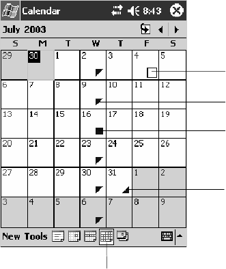
Windows Mobile 2003Chapter —2
50 700 Series Color Mobile Computer User’s Manual
Month view displays symbols to indicate the types of appointments you
have on a given day. An upward triangle indicates a morning appointment;
a downward triangle indicates an afternoon appointment. If you have ap-
pointments in the morning and afternoon, a solid square is displayed. If
you have an all day event not marked Free, a hollow square is displayed.
TaptoaccesstheMonthview
This displays an all day
event not marked Free.
This displays a morn-
ing appointment.
This displays appoint-
ments in both morning
and afternoon.
This displays an after-
noon appointment.
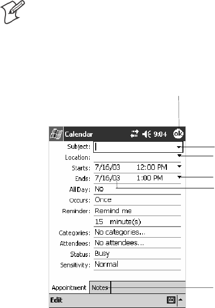
Windows Mobile 2003—Chapter 2
51700 Series Color Mobile Computer User’s Manual
Creating or Changing an Appointment
To create an appointment, tap New. To select a new date from a pop-up
calendar, tap the display date. To enter or select a new time, tap the dis-
play time. Enter the appointment details, and when finished, tap OK to
return to the calendar.
IfyouareworkinginDayview,tapthetimeslotforthenewappointment
and then tap New to have the time automatically entered for you.
To change an appointment, tap it in the calendar, and then tap Edit.
Change any appointment detail by tapping it and entering the new infor-
mation.
Note: Tap the arrows to the right of the description and location boxes to
choose from previous entries.
When entering a time, you can type military and abbreviated time forms,
such as 2300 (becomes 11:00 PM), 913pm (becomes 9:13 PM), 911 (be-
comes 9:11 AM), and 9p (becomes 9:00 PM).
Tap to return to the calendar
(the appointment is saved
automatically).
Tap to choose from
predefined text.
Tap to choose from previously
entered locations.
Taptoselectatime.
Tap to select a date.
Notes is a good place for
maps and directions.
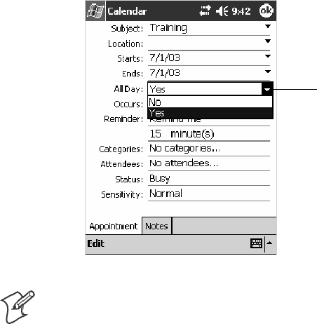
Windows Mobile 2003Chapter —2
52 700 Series Color Mobile Computer User’s Manual
Creating an All Day Event
To create an all day event, do the following:
1Tap New.
2Tap All Day, then select Yes.
Tap to select either
Yes or No whether
this is an all day
event.
Note: To change an all day event, switch to Day or Agenda view, tap the
event listed at the top of the calendar, and then tap Edit. Change any ap-
pointment detail by tapping it and entering the new information.
You cannot modify or create all day events with attendees on the 700 Col-
or Computer. If you create all day events with attendees on your desktop,
use ActiveSync to copy such events to the 700 Color Computer. Then,
view them in Calendar. For more information on copying files, see Active-
Sync Help. To use the device to schedule an appointment with attendees
lasting all day, set type to Normal, then adjust date and time accordingly.
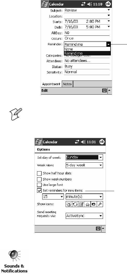
Windows Mobile 2003—Chapter 2
53700 Series Color Mobile Computer User’s Manual
Setting a Reminder for an Appointment
Do the following to set a reminder for an appointment in the calendar:
1Tap the appointment, then tap Edit to change the appointment.
2Tap Reminder and select Remind me.
3To change how many minutes before the appointment you are re-
minded, tap the minutes displayed, then select the new minutes from a
drop-down or enter the new minutes.
Tap minutes to change hours, days, or weeks.
TaptoselectRemind me
to enable the reminder
feature.
Note: To automatically set a reminder for all new appointments, in the
calendar, tap Tools >Options, select Set reminders for new items,then
tap the number and timeframe options to change the information given.
Tap this to set reminders
for new appointments
automatically.
To choose how you are reminded, for example by a sound, Tap Start >
Settings >thePersonal tab>theSounds & Notifications icon.
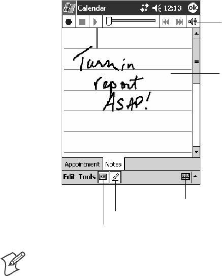
Windows Mobile 2003Chapter —2
54 700 Series Color Mobile Computer User’s Manual
Adding a Note to an Appointment
You can add written or typed notes and even recordings (if your device
supports recordings) to an appointment. This is a good place for maps,
drawings, and other detailed information.
1In the calendar, tap the appointment, then tap Edit.
2Tap the Notes tab to enter notes. For specific instructions, tap Start >
Help >Notes to see Notes Help.
Tap to activate the writing pad.
These are controls for
the recorder.
Use your stylus to write
or draw your informa-
tion here.
Tap to activate the recorder.
Tap to activate the keyboard.
Note: To edit an existing note, tap the appointment in the calendar, tap
Edit,thentaptheNotes tab.
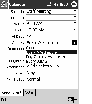
Windows Mobile 2003—Chapter 2
55700 Series Color Mobile Computer User’s Manual
Making an Appointment Recurring
Do the following to make a recurring appointment:
1In the calendar, tap the appointment, then tap Edit
2Tap Occurs and select a pattern from the list. Or, to create a new pat-
tern, tap <Edit pattern...>, and follow the steps in the wizard.
Select your recurrence
pattern from this drop-
down list.
Select <Edit pattern...>
to access the wizard
withwhichtocustom-
ize your recurrence.
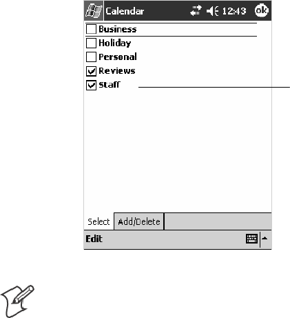
Windows Mobile 2003Chapter —2
56 700 Series Color Mobile Computer User’s Manual
Assigning an Appointment to a Category
1In the calendar, tap the appointment, then tap Edit.
2Tap Categories.
3On the Select tab, select the categories to which you want to assign the
appointment.
4To create a new category, tap the Add/Delete tab, enter the category
name, then tap Add. The new category is automatically selected in the
Select tab.
5Tap ok to return to the appointment.
A check mark indicates
a selected category.
Note: To find an appointment assigned to a category, tap Tools >Catego-
ries and select the type of appointment that you want displayed. To show
all appointments again, tap Tools >Categories and clear all categories.
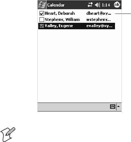
Windows Mobile 2003—Chapter 2
57700 Series Color Mobile Computer User’s Manual
Sending a Meeting Request
Use Calendar to schedule meetings with people who use Outlook or Pock-
et Outlook. When attendees receive a meeting request, they can accept or
decline the meeting. If they accept, the meeting is automatically added to
their schedule. In addition, their response is sent back to you, and your
calendar is updated.
Before you can send a meeting request, you must enter e-mail addresses in
Contacts Help and set up Inbox to send and receive messages. For more
information on sending and receiving meeting requests, tap Start >Help >
Calendar to see Calendar Help,andtapStart >Help >Inbox to see Inbox
Help.
1Tap New, then enter the meeting information.
2Hide the onscreen keyboard, if needed, then tap Attendees.Onlythose
contacts with e-mail addresses are displayed. Select the contacts you
want to invite, then tap ok to return to the appointment.
3Select other desired options and then tap ok.
4Inbox automatically creates a meeting request and sends it to the atten-
dees the next time you synchronize with your desktop. Textual notes
entered in the Notes tab (excluding writing or recordings) are sent also.
A check mark indicates
a selected attendee.
Note: If you are sending the meeting request through a connection to an
ISP or the network, rather than through synchronization with your desk-
top, tap Tools >Options.FromtheSend meeting requests via drop-down
list, tap the service to use to send the meeting request.
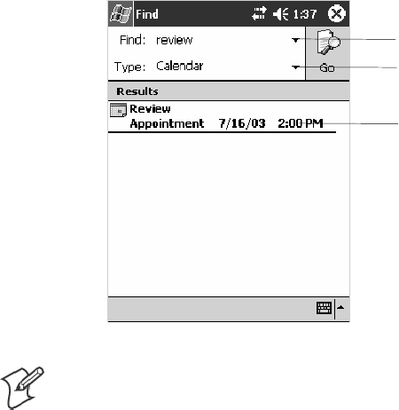
Windows Mobile 2003Chapter —2
58 700 Series Color Mobile Computer User’s Manual
Finding an Appointment
There are two ways to find an appointment:
STap Start >Find, enter the appointment name, tap the Type arrow and
select Calendar from the drop-down list, and then tap Go.
SIn the calendar, tap Tools >Categories and select the type of appoint-
ment you want displayed. To show all appointments again, tap Tools >
Categories and clear all categories.
Tap this to select from a drop-down
list or enter a phrase.
Tap this for a drop-down list of
areas where to search this phrase.
Tap this to see its details.
Note: In Find, you can tap the Find arrow to select from a list of items of
previously searched items or phrases.
Deleting an Appointment
1In the calendar, tap and hold the appointment.
2On the pop-up menu, tap Delete Appointment.Thenexttimeyou
synchronize, the appointment is also deleted from the desktop.
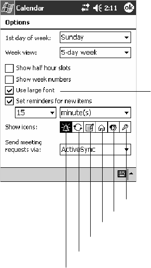
Windows Mobile 2003—Chapter 2
59700 Series Color Mobile Computer User’s Manual
Changing Calendar Options
In the calendar, tap Tools >Options.
STo see appointment indicators, select icons to display in Show icons.
You can choose to display indicators for such things as recurring ap-
pointments, appointments with notes, and appointments with remind-
ers. Tap and hold an icon to see its name.
SIf you are having trouble reading the calendar, select Use large font.
You may see less appointment information.
Tap this to view larger text.
Tap to indicate reminders.
Tap to indicate recurrences.
Tap to indicate notes.
Tap to indicate locations.
Tap to indicate attendees.
Tap to indicate private.
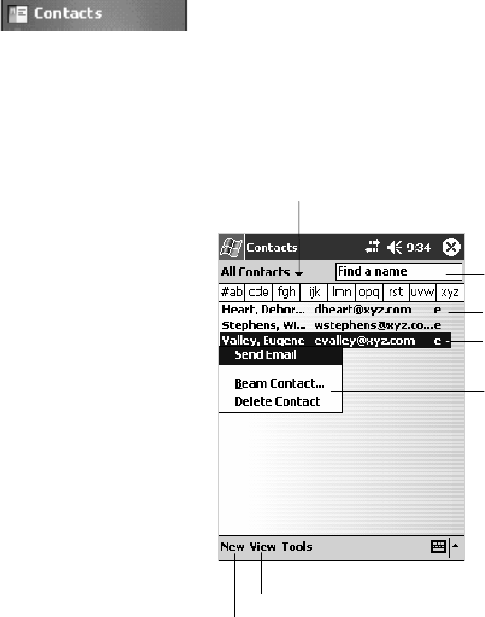
Windows Mobile 2003Chapter —2
60 700 Series Color Mobile Computer User’s Manual
Contacts: Tracking Friends and Colleagues
To switch to Contacts on the 700 Color Computer, tap Start >Contacts.
Contacts maintains a list of your friends and colleagues so that you can
easily find the information you are looking for, whether you are at home
or on the road. You can enter both personal and business information.
If you use Microsoft Outlook on your desktop, you can synchronize
contacts between your 700 Color Computer and your desktop.
Tap and enter part of a name
to quickly find it in the list.
Tap to create a new contact.
Select the category of contacts you
want displayed in the list.
Tap to see additional phone
numbers and e-mail addresses.
Tap to display or edit the
contact details.
Tap and hold to display a
pop-up menu of actions.
Tap to toggle to By Company (note the Name view)
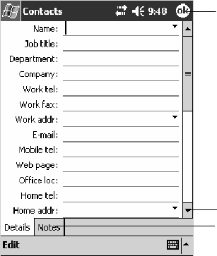
Windows Mobile 2003—Chapter 2
61700 Series Color Mobile Computer User’s Manual
Creating a Contact
1Tap New.
2Using the input panel, enter a name and other contact information.
Scroll down to see all available fields.
3To assign the contact to a category, scroll to and tap Categories and se-
lect a category from the list. In the contact list, you can display contacts
by category.
4To add notes, tap the Notes tab. You can enter text, draw, or create a
recording. For more information on creating notes, see “Notes: Captur-
ing Thoughts and Ideas”onpage71.
5When finished, tap OK to return to the contact list.
Tap to return to the contact list (the
contact is saved automatically).
Scroll to see more fields.
Notes is a good place for
maps and directions.
Synchronizing Contacts
Contacts stored on your device can be synchronized with Outlook contacts
stored on your desktop or with Mobile Information Server 2002 or later.
New items entered in one location are copied to the other during synchro-
nization. Handwritten notes and drawings are saved as pictures when syn-
chronizing with your desktop, but are removed when synchronizing with a
server.
For more information on synchronization, see ActiveSync Help on the
desktop.
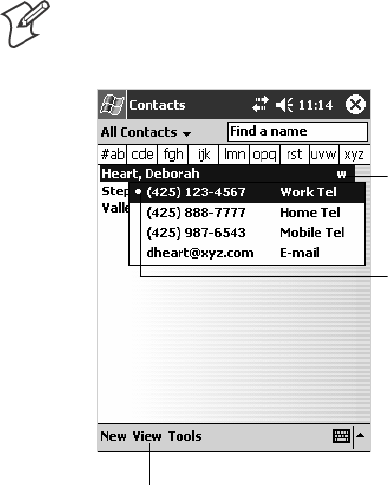
Windows Mobile 2003Chapter —2
62 700 Series Color Mobile Computer User’s Manual
Viewing Contacts
The contact list displays the contact name and the first primary phone
number or e-mail address specified for that contact. Contacts are ordered
by name of contact or company.
STap the default letter (home, work, mobile, or e-mail) to the right of
the contact to see additional phone numbers and e-mail addresses.
SSelect a contact and press the Left/Right controls to change the default
number, displayed as a letter to the right of the contact name.
STo see more contact information, tap the contact.
STo see a list of available actions for a contact via a pop-up menu, tap
andholdthecontact.
STo see a list of contacts employed by a specific company, tap View >By
Company. Then, tap the desired company name.
Note: You can change the appearance of the contact list by tapping Tools
>Options.
Tap for a list of phone num-
bers and e-mail addresses.
Tap to toggle By Name and By Company views.
Indicates the default number.
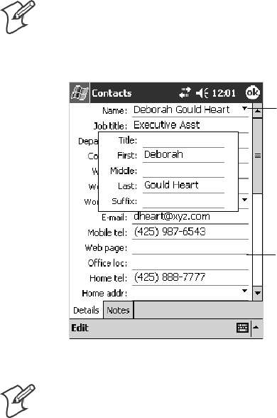
Windows Mobile 2003—Chapter 2
63700 Series Color Mobile Computer User’s Manual
Creating or Changing a Contact
STo create a contact, tap New. To enter notes, tap the Notes tab. When
finished, tap ok to return to the contact list.
STo change a contact, tap it in the contact list, and then tap Edit.To
cancel edits, tap Edit >Undo. When finished making changes, tap ok to
return to the contact list.
Note: Ifyouenteranamewithmorethantwowords,themiddleword
is recorded as a middle name. If your contact has a double first or last
name, tap the Name arrow and enter the names in the proper box.
Tap to access the Name
fields.
Tap anywhere outside the box
to close and return to details.
Note: New contacts are added to the displayed category.
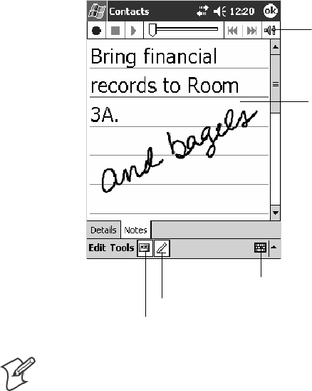
Windows Mobile 2003Chapter —2
64 700 Series Color Mobile Computer User’s Manual
Adding a Note to a Contact
You can add written or typed notes and even recordings (if your device
supports recordings) to a contact. Notes are handy for maps and drawings.
1In the contact list, tap the contact.
2Tap the Notes tab. For specific instructions, tap Start >Help >Notes
to see Notes Help.
Tap to activate the writing pad.
These are controls for
the recorder.
Use your stylus to write
or draw your informa-
tion here.
Tap to activate the recorder.
Tap to activate the keyboard.
Note: To edit an existing note, tap the contact, tap Edit,thentapthe
Notes tab.
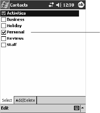
Windows Mobile 2003—Chapter 2
65700 Series Color Mobile Computer User’s Manual
Assigning a Contact to a Category
1In the contact list, tap the contact, and then tap Edit.
2Scroll to and tap Categories.
3On the Select tab, select the categories to which you want to assign the
contact.
4To create a new category, tap the Add/Delete tab, enter the category
name, then tap Add. The new category is automatically selected in the
Select tab.
5Tap ok to return to the contacts.
A check mark indicates
a selected category.
Copying a Contact
1In the contact list, select the contact. To select multiple contacts, tap
and drag.
2Tap Tools,andthenselectCopy Contacts.
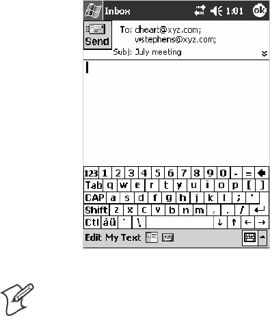
Windows Mobile 2003Chapter —2
66 700 Series Color Mobile Computer User’s Manual
Sending a Message to a Contact
1In the contact list, tap and hold the contact. To select multiple contacts,
tap and drag. Then, tap and hold the selected contacts.
2On the pop-up menu, select Send Email or Send SMS, depending
upon the type of message to send.
Note: To send an e-mail message, you must have an e-mail address config-
ured for the contact. To send an SMS (Short Messaging Service) message,
you must have an SMS number for the contact, which is usually the mo-
bile phone number.
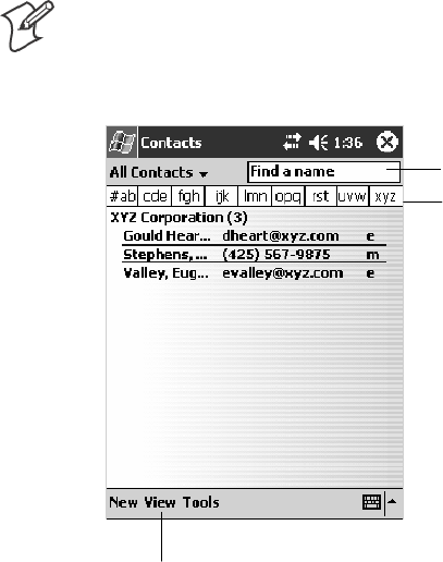
Windows Mobile 2003—Chapter 2
67700 Series Color Mobile Computer User’s Manual
Finding a Contact
There are four ways to find a contact:
STap Start >Find, enter the contact name (first, last, or middle), phone
number, or address, select Contacts for the type, then tap Go.
SFrom Contacts, start typing a contact name until you see it displayed on
the screen. To show all contacts again, tap the text box at the top of the
screen and clear the text, or tap the arrow to the right of the text box.
SIn the contact list, tap the category list (labeled All Contacts by default)
and tap the category to which you have assigned a contact. To show all
contacts again, select All Contacts.
STo view the names of companies for which your contacts work, in the
contact list, tap View >By Company. The number of contacts that
work for that company is displayed to the right of the company name.
Note: To quickly move through a long list of contacts, tap one of the sets
of letters displayed at the top of the contact list. This takes you to the con-
tact names beginning with those letters.
Taptojumptothatpor-
tion of the contacts list.
Enter the first few letters of
the contact in question here.
Tap to toggle to By Name (note the Company view)
Deleting a Contact
1In the contact list, tap and hold the contact. To select multiple contacts,
tap and drag. Then, tap and hold the selected contacts.
2On the pop-up menu, tap Delete Contact. The next time you synchro-
nize, the contact is deleted from the desktop also.
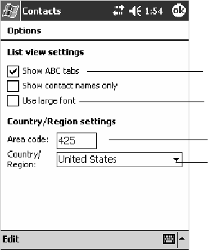
Windows Mobile 2003Chapter —2
68 700 Series Color Mobile Computer User’s Manual
Adding a Contact to Speed Dial
You can create speed dials to call frequently-called numbers with a single
tap. Before you can create a speed dial entry for a phone number, that
number must already exist in Contacts.
1From the Phone keypad, tap Speed Dial >New.
2Tapthedesiredcontactnameandnumber.
3In the Location field, tap the Up/Down arrows to select an available
location to assign as the new speed dial entry. The first speed dial loca-
tion is reserved for your voice mail.
To delete a speed dial entry, go to the Speed Dial list, tap and hold the
contact name in the box to the right of the assigned speed dial number,
then tap Delete.
Changing Contacts Options
In the contact list, tap Tools >Options.
SThe area code and country/region for new contacts are automatically
entered based on the information in Country/Region settings.
SIf you are having trouble reading the contacts in the contact list, select
Use large font.
STo increase the available space for displaying contacts in the list, clear
Show ABC tabs.
Enter the three-digit area code.
Select from a drop-down list.
Tap this to view larger text.
Clear this to view more
contacts per screen.
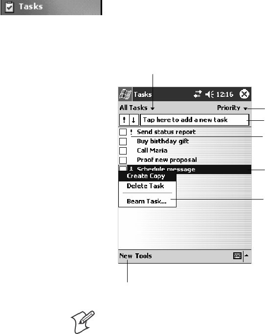
Windows Mobile 2003—Chapter 2
69700 Series Color Mobile Computer User’s Manual
Tasks: Keeping a To Do List
To switch to Tasks on your 700 Color Computer, tap Start >Tasks.
Use Tasks to keep track of what you have to do. A variety of task informa-
tion can display on the Today screen. If you use Microsoft Outlook on
your desktop, you can synchronize tasks between your device and desktop.
Select the sort order of the list.
Taptocreateanewtask.
Use this entry bar to assign a task quickly.
Tap to display or edit the
task details.
Tap and hold to display a
pop-up menu of actions.
Select the category of tasks you want displayed in the list.
Indicates a high priority.
Note: To change the way information is displayed in the list, tap Tools >
Options.
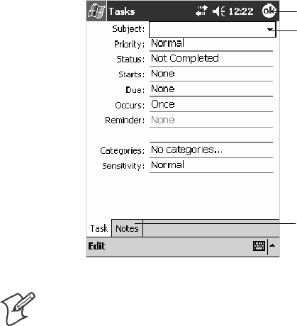
Windows Mobile 2003Chapter —2
70 700 Series Color Mobile Computer User’s Manual
Creating a Task
STo quickly create a task, enter text in the Tap here to add a new task
box at the top of the screen. If you do not see this box, tap Tools >
Entry Bar.
STo create a task with detailed information, such as start and due dates,
tap New. To enter notes, tap the Notes tab.
You can enter a start date and due date or enter other information by
first tapping the field. If the input panel is open, you need to hide it to
see all available fields.
You can enter text, draw, or create a recording. For more information
on creating notes, see “Notes: Capturing Thoughts and Ideas” on page 71.
STo change a task, tap it in the task list, and then tap Edit.
SUsing the onscreen keyboard, enter a description.
STo assign the task to a category, tap Categories and select a category
from the list. In the task list, you can display tasks by category.
SWhen finished, tap ok to return to the task list.
Taptoreturntothetasklist(the
task is saved automatically).
Tap to choose from predefined
subjects.
Notes is a good place for
maps and drawings.
Note: To quickly create a task with only a subject, tap Entry Bar on the
Tools menu. Then, tap Tap here to add a new task and enter your task
information.
Synchronizing Tasks
Tasks stored on your 700 Color Computer can synchronize with Micro-
soft Outlook on your desktop. Task synchronization is automatically se-
lected in ActiveSync.
New items entered on one computer are copied to the other during syn-
chronization. Handwritten notes and drawings are saved as metafiles (pic-
tures).
For more information on synchronization, see ActiveSync Help on the
desktop.
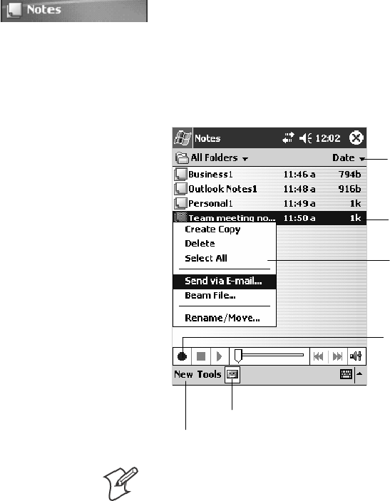
Windows Mobile 2003—Chapter 2
71700 Series Color Mobile Computer User’s Manual
Notes: Capturing Thoughts and Ideas
To switch to Notes on your 700 Color Computer, tap Start >Notes.
Notes helps you quickly capture your ideas, notes, and thoughts. You can
create a note using written and typed text, drawings, and recordings. You
can also share your notes with others through e-mail, infrared, and syn-
chronization with your desktop.
Tap to change the sort
order of the list.
Tap to create a new item.
Taptoopenanoteor
play a recording.
Tap and hold to display a
pop-up menu of actions.
Tap to record.
Tap to show or hide the Recording toolbar.
Note: To create documents with advanced formatting or templates, such
asbulletedlistsandtabs,usewordprocessingsoftwaredevelopedforyour
device, such as Pocket Word.
Creating a Note
To create your note, tap New,thenwrite,draw,type,orrecordyourin-
formation. For information about using the input panel, writing and dra-
wing, and creating recordings, see “Basic Skills” on page 26.
SWriting
Using the stylus, write directly on the screen.
SDrawing
Using the stylus, draw directly on the screen.
STyping
Using the input panel, enter typed text into the 700 Color Computer.
Do this by tapping keys on the onscreen keyboard or by using hand-
writing recognition software.
SRecording
Create a stand-alone recording or embed a recording into a note.

Windows Mobile 2003Chapter —2
72 700 Series Color Mobile Computer User’s Manual
Synchronizing Notes
Notes can be synchronized between your desktop and device either
through notes synchronization or file synchronization. Notes synchroniza-
tion synchronizes the notes on your 700 Color Computer with Outlook
Notes on your desktop. File synchronization synchronizes all notes on
your700ColorComputerwiththeMyDocumentsfolderforthe700
ColorComputeronyourdesktop.
To synchronize your notes through notes synchronization, first select the
Notes information type for synchronization in ActiveSync. The next time
you synchronize, all notes in My Documents and its subfolder on your
device appear in Outlook Notes on your desktop. Notes that contain only
text appear as regular notes in Outlook on your desktop, while notes con-
taining written text or drawings appear in the device format. In addition,
all notes in the Notes group in Outlook on the desktop appear in Notes on
the device.
To synchronize your notes as files, in ActiveSync, select the Files informa-
tion type for synchronization and clear the Notes information type. When
you select Files, the My Documents folder for the 700 Color Computer is
created on your desktop. All .PWI files placed in the My Documents fold-
er on your device and all .DOC files placed in the My Documents folder
forthe700ColorComputeronyourdesktoparesynchronized.Password-
protected files cannot be synchronized.
ActiveSync converts documents during synchronization. For more infor-
mation on synchronization or file conversion, see ActiveSync Help on the
desktop.
Note: When you delete or change an item on either your desktop or 700
Color Computer, the item is changed or deleted in the other location the
next time you synchronize.
Note: If you synchronize your notes using file synchronization and then
later decide to use notes synchronization, all of your notes are synchro-
nized with Outlook on your desktop and no longer store in the My Docu-
ments folder for the 700 Color Computer.

Windows Mobile 2003—Chapter 2
73700 Series Color Mobile Computer User’s Manual
Inbox: Sending and Receiving E-mail Messages
To switch to Inbox on your 700 Color Computer, tap Start >Inbox.
You can receive Internet e-mail messages and SMS messages in Inbox. In-
ternet e-mail messages are sent by using an address you receive from your
Internet service provider (ISP) or your employer. SMS messages are sent
and received through your wireless phone service provider by using a
phone number as the message address.
You can send and receive e-mail by synchronizing with your desktop, or
by connecting to a Post Office Protocol 3 (POP3) or Internet Message Ac-
cess Protocol 4 (IMAP4) mail server. You need to set up an e-mail account
for each method that you use except for Microsoft ActiveSync, which is set
upbydefault.TheActiveSyncfolderonyour700ColorComputerstores
messages that you send and receive through synchronization with a desk-
top. Account names appear as folders in the folder list (located on the left,
under the navigation bar) in the Inbox message list.
With synchronization, messages are synchronized between the device In-
box and the PC Inbox by using ActiveSync and Microsoft Exchange or
Microsoft Outlook. For more information, see “Synchronizing E-mail Mes-
sages”below.
When connecting to a POP3 or IMAP4 server, you use a modem to con-
nect to your Internet service provider (ISP), or a modem or Ethernet card
to connect to the local area network to which your e-mail server is connec-
ted. You can also use your phone to connect by using a cellular line con-
nection. For more information, see “Connecting to a Mail Server”onpage
75.
Synchronizing E-mail Messages
After selecting Inbox for synchronization in ActiveSync, e-mail messages
are synchronized as part of the general synchronization process. During
synchronization:
SMessages are copied from the Inbox folder on your desktop or the
Microsoft Exchange server to the Inbox folder on your 700 Color Com-
puter. (Note that you can only synchronize information directly with an
Exchange Server if your company is running Microsoft Mobile Infor-
mation Server 2002 or later.) By default, you receive messages from the
last three days only, the first 100 lines of each new message, and file at-
tachmentsoflessthan100KBinsize.
SMessages in the Outbox folder on your device are transferred to Ex-
change or Outlook and then sent from those programs.
SThe messages on the two computers are linked. When you delete a mes-
sage on your 700 Color Computer, it is deleted from your desktop the
next time you synchronize.
SMessages in subfolders in other e-mail folders in Outlook are synchro-
nized only if they were selected for synchronization in ActiveSync.
For information on initiating Inbox synchronization or changing synchro-
nization settings, see ActiveSync Help on your desktop or select Start >
Help >Connections to see Connections Help.
Windows Mobile 2003Chapter —2
74 700 Series Color Mobile Computer User’s Manual
Managing E-mail Messages and Folders
Each e-mail account and SMS account has its own folder hierarchy with
fivedefaultfolders:Inbox,Outbox,DeletedItems,Drafts,andSentItems.
The messages you receive and send through the mail account are stored in
these folders. You can also create additional folders within each hierarchy.
The Deleted Items folder contains messages that were deleted on the de-
vice. The behavior of the Deleted Items and Sent Items folders depends on
the Inbox options you have chosen.
The behavior of the folders you create depends on whether you are using
ActiveSync,SMS,POP3,orIMAP4.
SIf you use ActiveSync,
e-mail messages in the Inbox folder in Outlook automatically synchro-
nize with your device. You can select to synchronize additional folders
by designating them for ActiveSync. The folders you create and the
messages you move are then mirrored on the server. For example, if you
movetwomessagesfromtheInboxfoldertoafoldernamedFamily,
and you have designated Family for synchronization, the server creates a
copy of the Family folder and copies the messages into that folder. You
can then read the messages while away from your desktop.
SIf you use SMS,
messages are stored in the Inbox folder.
SIf you use POP3
and you move e-mail messages to a folder you created, the link is broken
between the messages on the device and their copies on the mail server.
The next time you connect, the mail server sees that the messages are
missing from the device Inbox and deletes them from the server. This
prevents you from having duplicate copies of a message, but it also
means that you no longer have access to messages that you move to fold-
ers created from anywhere except the 700 Color Computer.
SIf you use IMAP4,
the folders you create and the e-mail messages you move are mirrored
on the server. Therefore, messages are available to you anytime you con-
nect to your mail server, whether it is from your 700 Color Computer
or desktop. This synchronization of folders occurs whenever you con-
nect to your mail server, create new folders, or rename or delete folders
when connected.
For all accounts except ActiveSync, you can access folder options by tap-
ping Tools >Manage Folders.

Windows Mobile 2003—Chapter 2
75700 Series Color Mobile Computer User’s Manual
Connecting to a Mail Server
In addition to synchronizing e-mail messages with your desktop, you can
send and receive e-mail messages by connecting to an e-mail server using a
modem or network card connected to your 700 Color Computer. You
need to set up a remote connection to a network or an ISP, and a connec-
tion to your e-mail server. For more information, see “Getting Connected”
on page 98.
When you connect to the e-mail server, new messages are downloaded to
the 700 Color Computer Inbox folder, messages in the 700 Color Com-
puter Outbox folder are sent, and messages that were deleted on the e-mail
server are removed from the 700 Color Computer Inbox folder.
Messages that you receive directly from an e-mail server are linked to your
e-mail server rather than your desktop. When you delete a message on
your 700 Color Computer, it is also deleted from the e-mail server the
next time you connect based on the settings selected in ActiveSync.
You can work online or offline. When working online, you read and re-
spond to messages while connected to the e-mail server. Messages are sent
as soon as you tap Send, which saves space on your 700 Color Computer.
When working offline, once you have downloaded new message headers or
partial messages, you can disconnect from the e-mail server and then de-
cide which messages to download completely. The next time you connect,
Inbox downloads the complete messages you have marked for retrieval and
sends the messages you have composed.
Setting Up or Changing an Account
To set up an account:
STo set up a POP3 or IMAP4 e-mail account, tap Accounts >New Ac-
count. Follow the instructions in the New Account Wizard.
STo set up an SMS account, tap Accounts >Accounts, and then tap
SMS. Follow the instructions on the screen.
To change options for an account:
1Tap Accounts >Accounts.
2Tap the name of the account, and follow the instructions on the screen.
To delete an account:
1Tap Accounts >Accounts.
2Tap and hold the name of the account, and then tap Delete.
Note: You can set up several e-mail accounts including your ActiveSync
account, but you can set up only one SMS account.
Note: You cannot add a new account while connected. Tap Accounts >
Disconnect to disconnect.
Note: You cannot delete your SMS account.

Windows Mobile 2003Chapter —2
76 700 Series Color Mobile Computer User’s Manual
Downloading Messages from the Server
In Inbox, tap Accounts >Connect to open a connection to the Internet or
your corporate network, depending on the account. For more information,
tap Start >Help >Connections to see Connections Help.
1Tap Accounts and ensure that the account you want to use is selected
(marked by a bullet.)
2Tap Connect.Themessagesonyour700ColorComputerande-mail
server are synchronized: new messages are downloaded to the 700 Color
Inbox folder, messages in the 700 Color Outbox folder are sent, and
messages that were deleted from the server are removed from the 700
Color Inbox. Tap a message in the message list to open it.
3If you read a message and decide that you need the full copy, tap Edit >
Mark for Download while in the message window. If you are in the
message list, tap and hold the message, and then tap Mark for Down-
load. This also downloads message attachments if you selected those op-
tions when you set up the e-mail account. You can also choose to down-
load full copies of messages by default.
4When finished, tap Accounts >Disconnect.
Note: Receiving entire messages consumes storage memory.
Note: The size column in the message list displays the local size and server
size of a message. Even when a message has downloaded fully, these num-
bers may differ because the size of a message can vary between the server
and the device.
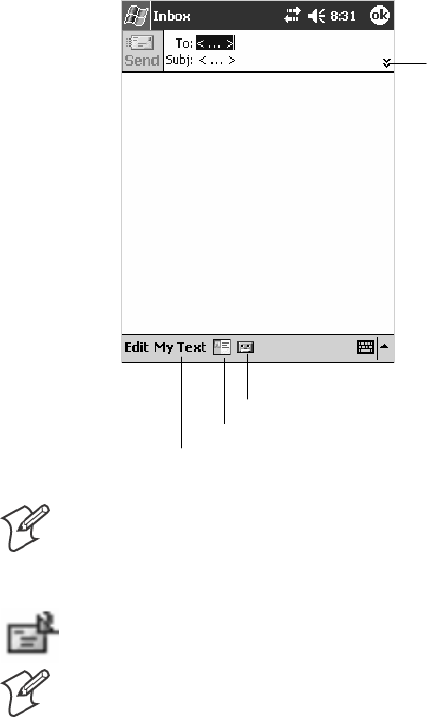
Windows Mobile 2003—Chapter 2
77700 Series Color Mobile Computer User’s Manual
Composing and Sending Messages
To compose a message:
1In the message list, tap New.
2To select an account, tap the From list and select “ActiveSync,” “SMS,”
or the desired e-mail account.
3Enter the e-mail address or SMS address of one or more recipients, sepa-
rating them with semicolons. To access addresses and phone numbers
from Contacts, tap To.
4Enter your message. To quickly add common messages, tap My Text
and tap a desired message.
5To check spelling, tap Edit >Spell Check.
6Tap Send. If you are working offline, the message is moved to the Out-
box folder and is sent the next time you connect.
Tap to show or hide the
complete header.
Tap to show or hide the recording tool bar.
Tap to display the Address Book.
Tap to insert common (preset) messages.
Note: If you are sending an SMS message and want to know if it was re-
ceived, before sending the message, tap Edit >Options >Request SMS
text message delivery notification.
You can directly call the sender of an SMS message by tapping the icon
shown to the left, then Call.
Note: Depending on the e-mail address options that you select, you can
use a directory service in addition to your contact list to verify names.
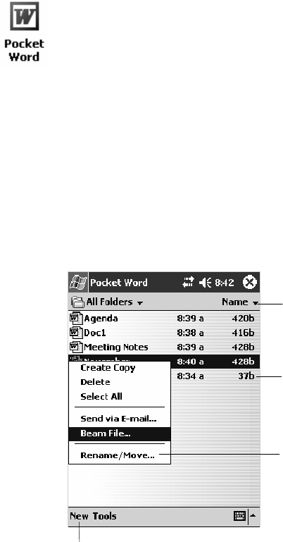
Windows Mobile 2003Chapter —2
78 700 Series Color Mobile Computer User’s Manual
Companion Programs
The companion programs consist of Microsoft Pocket Word, Microsoft
Pocket Excel, Windows Media Player, and Microsoft Reader. To switch to
a companion program on your 700 Color Computer, tap Start >
Programs, then tap the program name.
Pocket Word
Pocket Word works with Microsoft Word on your desktop to give you
access to copies of your documents. You can create new documents on
your 700 Color Computer, or you can copy documents from your desktop
to your 700 Color Computer. Synchronize documents between your desk-
top and your 700 Color Computer to have up-to-date content in both
locations.
Creating a Document
Use Pocket Word to create documents, such as letters or meeting minutes.
To create a new file, tap Start >Programs >Pocket Word >New.Youget
either a blank document or a template, depending on what you have se-
lected in the Tools >Options dialog box. Select an input mode from the
View menu.
You can open only one document at a time; when you open a second doc-
ument, you have to save the first. You can save a document you create or
edit in formats such as Word (.DOC), Pocket Word (.PSW), Rich Text
Format (.RTF), and Plain Text (.TXT).
Pocket Word contains a list of files stored on your 700 Color Computer.
Tap a file in the list to open it. To delete, make copies of, and send files,
tap and hold a file in the list, then, select the action on the pop-up menu.
Tap to change the sort
order of the list.
Tap to create a new document.
Tap to open a document.
Tap and hold an item to
see a pop-up menu of
actions.
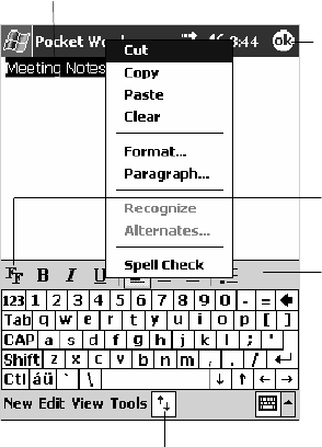
Windows Mobile 2003—Chapter 2
79700 Series Color Mobile Computer User’s Manual
You can enter information in Pocket Word in one of four modes (typing,
writing, recording, and drawing), which are displayed on the View menu.
Each mode has its own toolbar, which you can show and hide by tapping
the Show/Hide Toolbar buttononthecommandbar.
You can change the zoom magnification by tapping View >Zoom,then
select the percentage you want. Select a higher percentage to enter text and
a lower one to see more of your document.
If you are opening a Word document created on a desktop, you may select
View >Wrap to Window so that you can see the entire document.
To check spelling, select text, then tap Tools >Spell Check.Touseyour
new document as a template, move the document to the Templates folder.
You can insert the data in a document. First, make sure that no drawings
are selected, tap and hold anywhere on the document, then tap Insert
Date from the pop-up menu.
Typing Mode
Using the input panel, enter typed text into the document. For more in-
formation on entering typed text, see “Basic Skills” on page 26.
To format existing text and to edit text, first select the text. You can select
text as you do in a Word document, using your stylus instead of the mouse
to drag through the text you want to select. You can search a document to
find text by tapping Edit >Find/Replace.
Tap to show or hide the toolbar.
Tap to change formatting
options.
Taptoformattext.
Taptoreturntothe
document list (changes are
saved automatically).
Tap and hold to see a pop-up menu of actions.
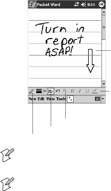
Windows Mobile 2003Chapter —2
80 700 Series Color Mobile Computer User’s Manual
Writing Mode
In writing mode, use your stylus to write directly on the screen. Ruled
lines are displayed as a guide, and the zoom magnification is greater than
in typing mode to allow you to write more easily. For more information
on writing and selecting writing, see “Basic Skills” on page 26.
Tap to select formatting options, such as
pen weight and line color.
With Space button selected,
drag to insert space. An arrow
appears showing the space
direction and size.
Tap to highlight selected text.
Space button.
Pen button.
Note: If you cross three ruled lines in a single stylus stroke, the writing
becomes a drawing, and can be edited and manipulated as described in
“Drawing Mode”onthenextpage.
Note: Written words are converted to graphics (metafiles) when a Pocket
Word document is converted to a Word document on your desktop.
Recording Mode
In recording mode, embed a recording into your document. Recordings
are saved as .WAV files. For more information on recording, see “Basic
Skills” on page 26.
For more information on using Pocket Word, tap Start >Help >Pocket
Word to see Pocket Word Help.
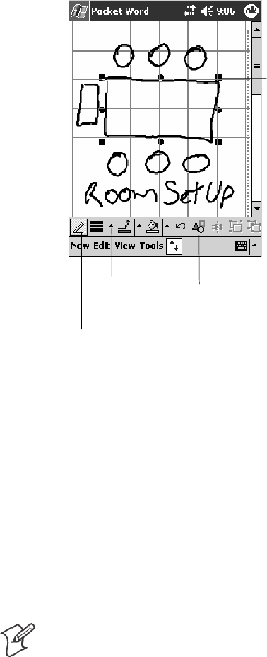
Windows Mobile 2003—Chapter 2
81700 Series Color Mobile Computer User’s Manual
Drawing Mode
In drawing mode, use your stylus to draw on the screen. Grid lines appear
as a guide. When you lift your stylus off the screen after the first stroke, a
drawing box indicating the boundaries of the drawing appears. Every sub-
sequent stroke within or touching the drawing box becomes part of the
drawing. For more information on drawing and selecting drawings, see
“Basic Skills” on page 26.
Tap to select formatting options, such as
line weight, fill color, and line color.
Resize an object by dragging
the selection handles.
Tap an arrow to see your choices.
Pen button.
Synchronizing Pocket Word Documents
Pocket Word documents can be synchronized with Word documents on
your desktop. To synchronize files, first select the Files information type
for synchronization in ActiveSync. When you select Files, the My Docu-
ments folder for the 700 Color Computer is created on your desktop.
Place all files you want to synchronize with the device in this folder. Pass-
word-protected files cannot be synchronized.
All Pocket Word files stored in My Documents and its subfolders are syn-
chronized with the desktop. ActiveSync converts documents during syn-
chronization.
For more information on synchronization or file conversion, see ActiveSync
Help on the desktop.
Note: When you delete a file on either your desktop or your 700 Color
Computer, the file is deleted in the other location the next time you syn-
chronize.
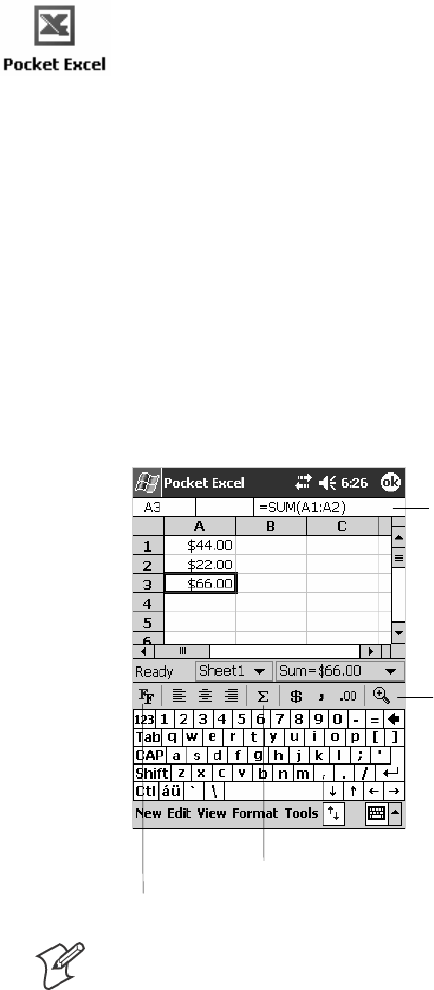
Windows Mobile 2003Chapter —2
82 700 Series Color Mobile Computer User’s Manual
Pocket Excel
You can create and edit workbooks and templates in Microsoft Pocket Ex-
cel as you do in Microsoft Excel on your desktop. Pocket Excel workbooks
are usually saved as .PXL files, but you can also save them in .XLS format.
When you close a workbook, it is automatically named and placed in the
Pocket Excel workbook list. You can attach a password to a workbook to
help ensure privacy.
Creating a Workbook
Use Pocket Excel to create workbooks, such as expense reports and mileage
logs. To create a new file, tap Start >Programs >Pocket Excel >New.A
blank workbook appears. Or, if you have selected a template for new
workbooks in the Tools >Options dialog box, that template appears with
appropriate text and formatting already provided. You can open only one
workbook at a time; when you open a second workbook, save the first.
You can save a workbook you create or edit in a variety of formats,
including Pocket Excel (.PXL) and Excel (.XLS). You can also save a
workbook as a template by moving the workbook to the Templates folder.
Pocket Excel contains a list of the files stored on your 700 Color Comput-
er. Tap a file in the list to open it. To delete, make copies of, and send
files, tap and hold a file in the list. Then select the appropriate action from
the pop-up menu.
Pocket Excel provides fundamental spreadsheet tools, such as formulas,
functions, sorting, and filtering. To display the toolbar, tap View >
Toolbar.
Zoom button.
Format button.
AutoSum button.
Cell contents appear
here as you enter them.
Note: If your workbook contains sensitive information, you can protect it
with a password. To do so, open the workbook, tap Edit >Password.Ev-
ery time you open the workbook, enter a password, preferably one that is
easy for you to remember but hard for others to guess.
Windows Mobile 2003—Chapter 2
83700 Series Color Mobile Computer User’s Manual
Tips for Working in Pocket Excel
Note the following when working in large worksheets in Pocket Excel:
SView in full-screen mode to see as much of your worksheet as possible.
Tap View >Full Screen.Toexitfull-screenmode,tapRestore.
STap View >Zoom and select a percentage so that you can easily read
the worksheet.
SShow and hide window elements. Tap View and then tap the elements
you want to show or hide.
SFreeze panes on a worksheet. First select the cell where you want to
freeze panes. Tap View >Freeze Panes.Youmightwanttofreezethe
top and leftmost panes in a worksheet to keep row and column labels
visible as you scroll through a sheet. Tap View >Unfreeze Panes to
undo this process.
SSplit panes to view different areas of a large worksheet. Tap View >
Split. Then drag the split bar to where you want it. To remove the split,
tap View >Remove Split.
SShow and hide rows. To hide a row, select a cell in the row you want to
hide. Then tap Format >Row >Hide. To show a hidden row, tap
Tools >Go To, and then type a reference that is in the hidden row.
Then tap Format >Row >Unhide.
SDo the same to show and hide columns. To hide a column, select a cell
in the column you want to hide. Then tap Format >Column >Hide.
To show a hidden column, tap Tools >Go To, and then type a refer-
ence that is in the hidden column. Then tap Format >Column >Un-
hide.
For more information on using Pocket Excel, tap Start >Help >Pocket
Excel to see Pocket Excel Help.

Windows Mobile 2003Chapter —2
84 700 Series Color Mobile Computer User’s Manual
MSN Messenger
MSN Messenger on your 700 Color Computer provides the same chat
environment as MSN Messenger on your desktop. These features include:
SSeeing who is online
SSending and receiving instant messages
SHaving an instant message conversation with a group of contacts
STelling contacts that you are unavailable
SBlocking contacts from seeing your status or sending you messages
To use MSN Messenger, you need a Microsoft Passport account, or a
Microsoft Exchange e-mail account that your employer provides. Once
youhaveoneoftheseaccounts,dothefollowing:
1Set up a connection on your 700 Color Computer, such as a modem or
wireless connection, that enables you to connect to the Internet.
2SetupanaccountinMSNMessenger.
3Sign in to MSN Messenger.
Note: To set up a free Hotmail account, go to http://www.hotmail.com.
To set up a Microsoft Passport account, go to http://www.passport.com.
To set up an Exchange account, see your network administrator.
For more information on using MSN Messenger, tap Start >Help >MSN
Messenger to see MSN Messenger Help.
To switch to MSN Messenger, tap Start >Programs >MSN Messenger.
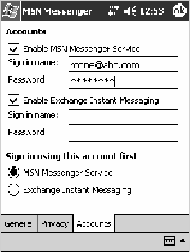
Windows Mobile 2003—Chapter 2
85700 Series Color Mobile Computer User’s Manual
Setting Up an Account
Before you can use MSN Messenger, you must set up the instant messag-
ing accounts to use. For MSN Messenger Service, you must have a Micro-
soft Passport or Hotmail account. For Exchange Instant Messaging, you
must have an Exchange account.
1Create a connection for your device. To use MSN Messenger Service,
set up a connection to the Internet; to use Exchange Instant Messaging,
set up a connection to your corporate network. See page 98 for more
information on getting connected.
2In MSN Messenger, tap Tools >Options >theAccounts tab.
3Select Enable MSN Messenger Service or Enable Exchange Instant Mes-
saging.
4Enter your sign-in name and password for the selected accounts. Your
sign-in name is usually in the username@domain.com form.
5If you selected both accounts, under Sign in using this account first, se-
lect which account to sign in to first.
Signing In and Out
STo sign in, tap anywhere on the screen. Follow the directions on the
screen.
STo sign out, tap Tools >Sign Out.
STo sign in upon connecting, tap Tools >Options >General and select
the Run this program upon connection box.
SSigning in to an Exchange account may take several minutes depending
upon your connection speed. Reducing the number of Exchange con-
tacts decreases your sign-in time.
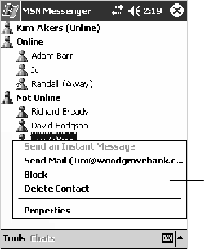
Windows Mobile 2003Chapter —2
86 700 Series Color Mobile Computer User’s Manual
Working with Contacts
The MSN Messenger window shows all of your messenger contacts at a
glance, divided into Online and Not Online categories. From this view,
while connected, you can chat, send e-mail, block the contact from chat-
ting with you, or delete contacts from your list using the pop-up menu.
Tap a contact to start a
chat.
Tap and hold to display a
pop-up menu of actions.
To add a contact, tap Tools >Add a Contact and follow the directions on
the screen.
To delete a contact, tap and hold the contact’s name, then tap Delete
Contact from the pop-up menu.
To see others online without being seen, tap Tools >My Status >Appear
Offline.
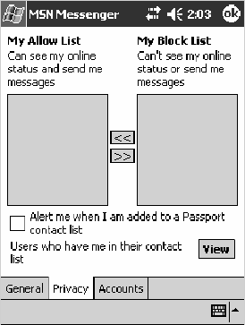
Windows Mobile 2003—Chapter 2
87700 Series Color Mobile Computer User’s Manual
Managing Contacts
To be alerted each time you are added to a contact list, tap Tools >Op-
tions >thePrivacy tab.
STo block a contact from seeing your status and sending you messages,
tap the contact and tap the right arrow. This moves the contact to the
My Block List.
STo unblock a contact, tap the contact and tap the left arrow. This
moves the contact to the My Allow List.
STo receive an alert when someone adds you to their contacts list, select
Alert me when I am added to a Passport contact list.
STo see who has you listed as a contact, tap View.
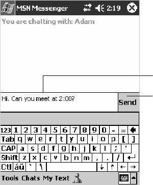
Windows Mobile 2003Chapter —2
88 700 Series Color Mobile Computer User’s Manual
Sending a Message
STap a contact to whom you want to send a message. Enter your message
in the text entry area at the bottom of the screen and tap Send.To
quickly add common messages, tap My Text and tap a desired message.
STo invite another contact to an ongoing chat, tap Tools >Invite and
tap a contact.
STo see who is already chatting or to switch between chats, tap Chats.
Enter a message.
Tap to send message.
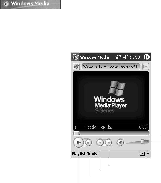
Windows Mobile 2003—Chapter 2
89700 Series Color Mobile Computer User’s Manual
Windows Media Player for Windows Mobile
Use Microsoft Windows Media Player for Windows Mobile to play digital
audio and video files that are stored on your 700 Series Computer or on a
network.
To switch to Windows Media Player on your 700 Color Computer, tap
Start >Windows Media.
Use Microsoft Windows Media Player on your desktop to copy digital au-
dio and video files to your 700 Color Computer. You can play Windows
Media and MP3 files on your Windows Mobile.
Indicates the progress
of the current track.
Tap to adjust volume.
Tap to skip to the next song.
Tap to play a previous song.
Taptostop.
Tap to play or pause.
For more information about using Windows Media Player for Windows
Mobile, tap Start >Help >Windows Media Player to see Windows Media
Player Help.

Windows Mobile 2003Chapter —2
90 700 Series Color Mobile Computer User’s Manual
Microsoft Reader
Use Microsoft Reader to read eBooks on your 700 Color Computer.
Download books to your desktop from your favorite eBook Web site.
Then, use ActiveSync to copy the book files to your activated 700 Color
Computer. The books appear in the Reader Library, where you can tap
them in the list to open them. Each book consists of a cover page, an op-
tional table of contents, and the pages of the book. You can:
SPage through the book by using the Up/Down control on your 700
ColorComputerorbytappingthepagenumberoneachpage.
SAnnotate the book with highlighting, bookmarks, notes, and drawings.
SSearch for text and look up definitions for words.
The Guidebook contains all the information needed to use the software.
To open the Guidebook, tap Help on the Reader command bar. Or, on a
book page, tap and hold on the book title, and then tap Help on the pop-
up menu.
To switch to Microsoft Reader, tap Start >Programs >Microsoft Reader.
Getting Books on Your 700 Color Computer
You can download book files from the Web. Just visit your favorite eBook
retailer and follow the instructions to download the book files.
Sample books and a dictionary are also included in the MSReader folder in
the Extras folder on the Windows Mobile Companion CD.
Use ActiveSync to download the files from your desktop to your activated
mobile computer as described in the Read Me file in the MSReader folder.
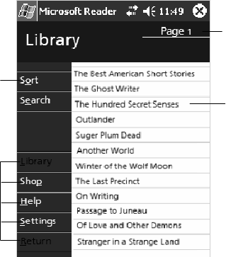
Windows Mobile 2003—Chapter 2
91700 Series Color Mobile Computer User’s Manual
Using the Library
The Library is your Reader home page; it displays a list of all books stored
onyour700ColorComputerorstoragecard.ToopentheLibrary:
1On the Reader command bar, tap Library.
2On a book page, tap the book title, then tap Library on the pop-up
menu.
3To open a book, tap its title in the Library list.
Tap to scroll through
the Library list.
Tap to open a book.
Tap here to navigate to
other parts of the Reader.
Tap to select a sort order.
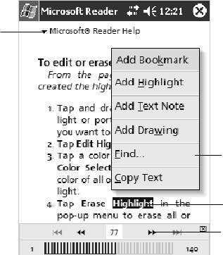
Windows Mobile 2003Chapter —2
92 700 Series Color Mobile Computer User’s Manual
Reading a Book
Each book consists of a cover page, an optional table of contents, and the
pages of the book. Navigation options are listed in the bottom portion of
the cover page.
Thefirsttimeyouopenabook,gotothefirstpageortothetableofcon-
tents, if there is one. Subsequently, whenever you open the book, you are
automatically taken to the last page read.
In addition to the text, each book page includes a page number and book
title.
Taptoselecta
navigation option.
Select an option after
dragging to select a
text.
Drag to select text.
Tap arrows to turn the
page, or tap and hold
page number to bring up
page riffle.
You can also page through a book by using the Up/Down/Left/Right con-
trols on your 700 Color Computer.

Windows Mobile 2003—Chapter 2
93700 Series Color Mobile Computer User’s Manual
Using Reader Features
Reading a book electronically gives you several options not available with
paper books. These options are available from any book page.
Select text by dragging across the text on the page. Then, tap an option on
the pop-up menu, as described here:
Searching for Text Find text in a book by tapping Find on the pop-up menu. Enter the word you want to
search for, and tap the desired Find option. Reader highlights found text on the page. To
close Find, tap outside the box. To return to your original page, tap the title and then tap
Return on the pop-up menu.
Copying Text You can copy text from books that support this feature into any program that accepts
text. On a book page, select the text you want to copy. Then, tap Copy Text on the pop-
up menu. The text can be pasted into the program of your choice.
Adding Bookmarks When you add a bookmark to a book, a color-coded bookmark icon appears in the right
margin. You can add multiple bookmarks to a book. Then, from anywhere in the book,
tap the bookmark icon to go to the bookmarked page.
Highlighting Text When you highlight text, it appears with a colored background.
Attaching Notes to Text When you attach a note to text, you enter the text in a notepad that appears on top of the
book page. A Note icon displays in the left margin. To show or hide the note, tap the
icon.
Adding Drawings When you add a drawing, a Drawing icon appears in the bottom-left corner of the page,
and drawing tools appear across the bottom of the page. Draw by dragging your stylus.
Annotations Index To see a list of a book’s annotations, including bookmarks, highlights, text notes, and
drawings, tap Annotations Index on the book’s cover page. You can tap an entry in the
list to go to the annotated page.
Removing a Book
When you finish reading a book, you can delete it to conserve space on
your 700 Color Computer. If a copy of the book is stored on your desk-
top, you can download it again at any time.
To remove a book from your 700 Color Computer, tap and hold the title
in the Library list, and then tap Delete on the pop-up menu.

Windows Mobile 2003Chapter —2
94 700 Series Color Mobile Computer User’s Manual
Pocket Internet Explorer
Use Microsoft Pocket Internet Explorer to view Web or WAP pages in
either of these ways:
SDuring synchronization with your desktop, download your favorite
links and mobile favorites that are stored in the Mobile Favorites sub-
folder in Internet Explorer on the desktop.
SConnect to an ISP or network and browse the Web. To do this, create
the connection first, as described in “Getting Connected” on page 98.
When connected to an ISP or network, you can also download files and
programs from the Internet or intranet.
To switch to Pocket Internet Explorer on your 700 Color Computer, tap
Start >Internet Explorer.
The Mobile Favorites Folder
Only items stored in the Mobile Favorites subfolder in the Favorites folder
in Internet Explorer on your desktop are synchronized with your 700 Col-
or Computer. This folder was created automatically when you installed
ActiveSync.
Favorite Links
During synchronization, the list of favorite links in the Mobile Favorites
folder on your desktop is synchronized with Pocket Internet Explorer on
your 700 Color Computer. Both computers are updated with changes
made to either list each time you synchronize. Unless you mark the favor-
ite link as a mobile favorite, only the link is downloaded to your 700 Color
Computer. Connect to your ISP or network to view the content.
1In ActiveSync on your desktop, click Tools >Options, and select “Fa-
vorites” from the Mobile Device list. For more information on using
ActiveSync, see ActiveSync Help on the desktop.
2In Internet Explorer on your desktop, save or move favorite links to the
Mobile Favorites subfolder in the Favorites list via Favorites >Organize
Favorites. For more information on using Internet Explorer, see Internet
Explorer Help on the desktop.
3Connect your 700 Color Computer to your desktop. If synchronization
does not start automatically, in ActiveSync on your desktop, click Sync.
Windows Mobile 2003—Chapter 2
95700 Series Color Mobile Computer User’s Manual
Mobile Favorites
If you are using Microsoft Internet Explorer 5.0 or later on your desktop,
you can download mobile favorites to your 700 Color Computer. Syn-
chronizing mobile favorites downloads Web content to your 700 Color
Computer so that you can view pages while you are disconnected from
your ISP and desktop.
Use the Internet Explorer plug-in installed with ActiveSync to create mo-
bile favorites quickly. To create a mobile favorite:
1In ActiveSync on your desktop, click Tools >Options,andselect
“Favorites” from the Mobile Device list. For more information on using
ActiveSync, see ActiveSync Help on the desktop.
2In Internet Explorer 5.0 or greater on your desktop, browse to the page
you want to view offline, then click Tools >Create Mobile Favorite.
3To change the link name, enter a new name in the Name box.
4In the Update box, select a desired update schedule to keep the page in
the Mobile Favorites folder up to date. You can also update content by
clicking Tools >Synchronize in Internet Explorer.
5To save the link in a subfolder of Mobile Favorites, click Create In and
select the desired subfolder.
6Click OK. Internet Explorer downloads the latest version of the page to
your desktop.
7To download the pages that are linked to the mobile favorite you just
created, in Internet Explorer on the desktop, right-click the mobile
favorite, then click Properties.OntheDownload tab, specify the
number of links deep you want to download. To conserve 700 Color
Computer memory, go only one level deep.
8Connect your 700 Color Computer to your desktop. If synchronization
between your 700 Color Computer and desktop does not start, in Acti-
veSync on your desktop, click Sync.
Mobile favorites take up storage memory on your 700 Color Computer.
To minimize the amount of memory used:
SIn the settings for the Favorites information, type in ActiveSync op-
tions, turn off pictures and sounds, or stop some mobile favorites from
being downloaded to the 700 Color Computer. For more information,
see ActiveSync Help.
SLimit the number of downloaded linked pages. In Internet Explorer on
thedesktop,right-clickthemobilefavoriteyouwanttochangeandthen
Properties.IntheDownload tab, specify “0” or “1” for the number of
linked pages you want to download.
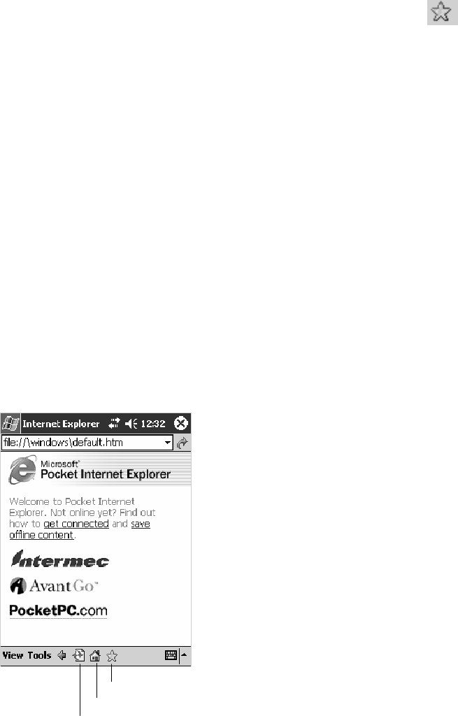
Windows Mobile 2003Chapter —2
96 700 Series Color Mobile Computer User’s Manual
Using AvantGo Channels
AvantGo is a free interactive service that gives you access to personalized
content and thousands of popular Web sites. You subscribe to AvantGo
channels directly from your 700 Color Computer. Then, you synchronize
your 700 Color Computer and desktop, or connect to the Internet to
download the content. For more information, visit the AvantGo Web site.
To synchronize an AvantGo channel:
1In Pocket Internet Explorer on your 700 Color Computer, tap to
display your list of favorites.
2Tap the AvantGo Channels link.
3Tap Activate.
4Follow the directions on the screen. Synchronize your 700 Series Com-
puterwithyourdesktop,thentapMy Channels to complete the Avant-
Go setup.
5When synchronization is complete, tap the AvantGo Channels link in
your list of favorites to see a few of the most popular channels.
To add or remove channels, tap the Add or Remove link.
Using Pocket Internet Explorer
YoucanusePocketInternetExplorertobrowsemobilefavoritesandchan-
nels that were downloaded to your 700 Color Computer without connect-
ing to the Internet. You can also connect to the Internet through an ISP or
a network connection and browse the Web.
Favorites button
Home button
Refresh button
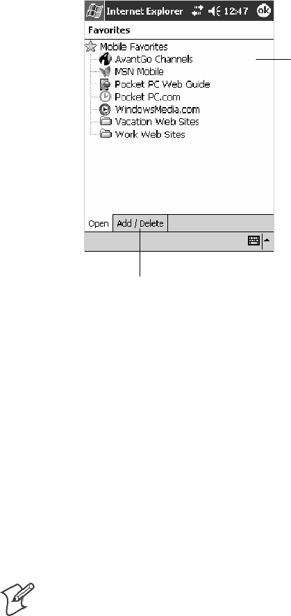
Windows Mobile 2003—Chapter 2
97700 Series Color Mobile Computer User’s Manual
Viewing Mobile Favorites and Channels
1Tap the Favorites button to display your list of favorites.
2Tap the page you want to view.
Tap the favorite you want
to view.
Tap to add or delete a folder or favorite link.
The page that was downloaded the last time you synchronized with your
desktop opens. If the page is not on your 700 Color Computer, the favor-
ite is dimmed. Synchronize with your desktop again to download the page
to your 700 Color Computer, or connect to the Internet to view the page.
Browsing the Internet
1Set up a connection to your ISP or corporate network using Connec-
tions, as described in “Getting Connected” on page 98.
2To connect and start browsing, do one of the following:
STap the Favorites button, and then tap the favorite you want to view.
STap View >Address Bar. In the address bar that appears at the top of
the screen, enter the Web address you want to visit and then tap Go.
Tap the arrow to choose from previously entered addresses.
Note: To add a favorite link while using the 700 Color Computer, go to
the page you want to add, tap and hold on the page, and tap Add to
Favorites.

Windows Mobile 2003Chapter —2
98 700 Series Color Mobile Computer User’s Manual
Getting Connected
You can set up connections to the Internet and corporate network at work
to do such activities as browsing the Internet or intranet, sending and re-
ceiving e-mail and instant messages, and synchronizing information using
ActiveSync.
Connections can be made using a modem, wireless network, or Ethernet.
You can use a modem connection to set up connections with an external
modem, or through your mobile phone network using a cellular line or
GPRS.
Your 700 Series Computer has two groups of connection settings: My ISP
and My Work Network. Use My ISP settings to connect to the Internet.
Use My Work Network settings to connect to any private network, such as
a corporate network used at work.
SMy ISP: Once connected, you can send and receive e-mail messages by
using Inbox and view Web or WAP pages by using Pocket Internet Ex-
plorer. The communication software for creating an ISP connection is
already installed on your 700 Series Computer. Your service provider
provides the software needed to install other services, such as paging and
fax services. If this is the method you want to use, see “Connecting to an
Internet Service Provider”onpage98.
SMy Work Network: Connect to the network at your company or orga-
nization where you work. Once connected, you can send and receive
e-mail messages by using Inbox, view Web or WAP pages by using
Pocket Internet Explorer, and synchronize with your desktop. If this is
the method you want to use, see “Connecting to Work” on page 102.
Connecting to an Internet Service Provider
You can connect to your ISP, and use the connection to send and receive
e-mail messages and view Web or WAP pages. You can connect to your
ISP via a modem connection.
Obtain the following information from your ISP. Some ISPs require infor-
mation in front of the user name, such as MSN/username.
SISP dial-up access telephone number
SUser name
SPassword
If you do not have a modem dock, use a NULL modem cable and ap-
propriate adapters to connect an external modem to your 700 Color Com-
puter through the serial port.
To view additional information for any screen in the wizard or while
changing settings, tap the Help icon.
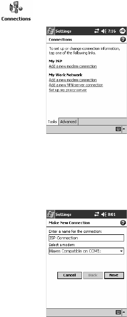
Windows Mobile 2003—Chapter 2
99700 Series Color Mobile Computer User’s Manual
1Tap Start >Settings >theConnections tab>theConnections icon. In
My ISP,tapAdd a new modem connection.
2Enter a name for the connection, such as “ISP Connection.”
In the Select a modem list, select your modem type. If your modem
type does not appear, try reinserting the 700 Color Computer into your
modem dock. If you are using an external modem that is connected to
your 700 Color Computer with a cable, select “Hayes Compatible on
COM1.” Tap Next to continue.
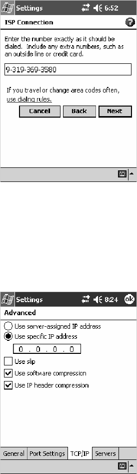
Windows Mobile 2003Chapter —2
100 700 Series Color Mobile Computer User’s Manual
3Enter the access phone number, then tap Next.
4You should not need to change any settings in Advanced.MostISPs
now use a dynamically-assigned address. If the ISP you are connecting
to does not use a dynamically-assigned address, tap Advanced >the
TCP/IP tab, tap Use specific IP address, then enter the address. Tap ok
to close the Advanced page.
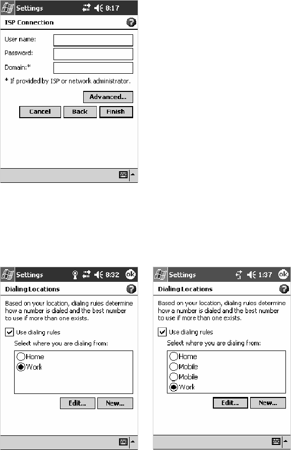
Windows Mobile 2003—Chapter 2
101700 Series Color Mobile Computer User’s Manual
Enter the user name, password, and domain (if provided by an ISP or
your network administrator), then tap Finish.
5Tap the Advanced tab from the Connections screen, then tap Select
Location to specify your current location. These settings apply to all
connections. Tap Use dialing rules,tapOK,then tap Edit to continue.
730, 740, 750, 760 Screens 741, 751, 761 Screens
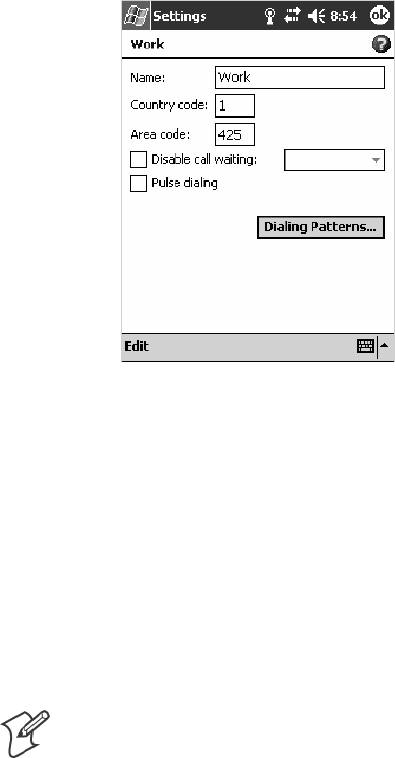
Windows Mobile 2003Chapter —2
102 700 Series Color Mobile Computer User’s Manual
6Specify your current phone type. If your phone type is pulse dialing,
check the Pulse dialing box. If your type is tone dialing (as most phone
lines are), then clear the Pulse dialing box. Continue to tap ok to close
each page and return to the Settings page.
To start the connection, start using one of the following programs. Once
connected, you can:
SSend and receive e-mail messages by using Inbox. Before you can use
Inbox, you need to provide the information it needs to communicate
with the e-mail server. For specific instructions, see “Connecting Directly
to an E-mail Server” on page 114.
SVisit Web and WAP pages by using Pocket Internet Explorer. For more
information, see “Pocket Internet Explorer” on page 94.
SSend and receive instant messages with MSN Messenger. For more in-
formation, see “MSN Messenger” on page 84.
Note: To change modem connection settings in My ISP, tap Manage
existing connections. Select the desired modem connection, tap Settings,
and follow the instructions on the screen.
Connecting to Work
If you have access to a network at work, you can send e-mail messages,
view intranet pages, synchronize your 700 Color Computer, and possibly
access the Internet. You can connect to work in one of two ways:
Create a modem connection by using a RAS (Remote Access Server) ac-
count. Before you can create this modem connection, your network ad-
ministrator needs to set up a RAS account for you. Your network adminis-
trator may also give you Virtual Private Network (VPN) settings.
Get a dial-up access telephone number, a user name, and a password from
your network administrator. If your 700 Color Computer does not have
access to a mobile phone network, insert your 700 Color Computer into a
modem dock.
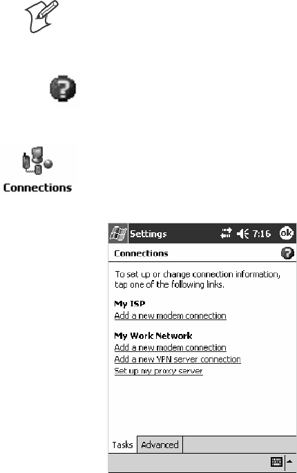
Windows Mobile 2003—Chapter 2
103700 Series Color Mobile Computer User’s Manual
Note: To change modem connection settings in My Work Network, tap
Manage existing connections. Select the desired modem connection, tap
Edit, and follow the instructions on the screen.
To view additional information for any screen in the wizard or while
changing settings, tap the Help icon.
Creating a Modem Connection to Work
1Tap Start >Settings >theConnections tab>theConnections icon.
Tap Add a new modem connection beneath My Work Network to ini-
tiate this procedure.
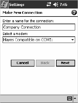
Windows Mobile 2003Chapter —2
104 700 Series Color Mobile Computer User’s Manual
2Enter a name for the connection, such as “Company Connection.” In
the Select a modem list, select your modem type. If your modem type
does not appear, try reinserting your 700 Color Computer into your
modem dock.
SIf using an external modem connected to your 700 Computer with a
cable, select “Hayes Compatible on COM1.”
SIf using any type of external modem, select the modem by name. If a
listing does not exist for your external modem, select “Hayes Com-
patible on COM1.”
SWireless connections can be made via a mobile phone network or
GPRS. If using a mobile phone network to connect, select “Cellular
Line.” If using GPRS, tap “Cellular Line (GPRS).”
Tap Next to continue.
3Enter the access phone number, using some of the following guidelines.
If you know part of the phone number changes frequently as you travel,
create dialing rules to avoid creating numerous modem connections for
the same phone number. For more information, tap Use Dialing Rules.
SEnterthephonenumberexactlyasyouwantitdialed.Forexample,
if you call from a business complex or hotel that requires a nine be-
fore dialing out, enter “9” in front of the phone number.
SEnter the APN provided by your mobile phone service provider.
SWhen using dialing rules, phone numbers are entered differently. To
use additional numbers, such as a “9” to dial from an office complex
or hotel, you must use additional dialing rules or change dialing pat-
terns. See “Create Dialing Rules” via your online help for information.
aIn the Country/Region box, enter the appropriate code when dial-
ing internationally. For more information, contact an operator at
your local phone company.
bIn the Area code box, enter the area code. Area codes are not need-
ed in all countries.
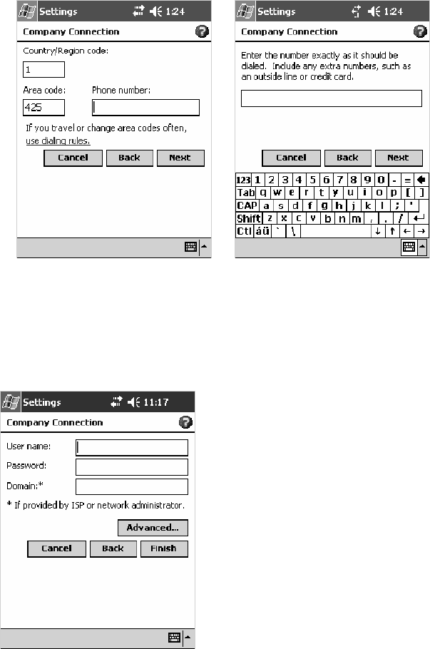
Windows Mobile 2003—Chapter 2
105700 Series Color Mobile Computer User’s Manual
cEnter the main phone number, then tap Next to continue.
4Enter the user name, password, and domain (if provided by an ISP or
your network administrator). If a domain name was not provided, try
the connection without entering a domain name.
5You should not need to change any advanced settings. Instances where
you are to change advanced settings include the following. To change
advanced settings, tap Advanced.Otherwise,tapFinish.
SYou want to change baud rate settings, dialing string commands, or
credit card options.
SYou need to change port settings.
SThe server you are connecting to does not use dynamically-assigned
addresses, and you need to enter your TCP/IP settings.
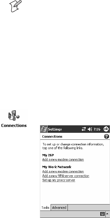
Windows Mobile 2003Chapter —2
106 700 Series Color Mobile Computer User’s Manual
Note: The following information applies when you have “Wireless
802.11” selected via the NDISTRAY pop-up menu (see page 129).
Creating a Wireless Network Connection
Microsoft Corporation’s wireless network configuration tool is called
“Wireless Zero Config.” Intermec Technologies recommends that you use
the Wireless Network control panel applet instead as it offers more security
choices and exhibit better roaming behavior. Information about the Wire-
less Network control panel applet is in Appendix A.
Networks already configured are preferred networks and are listed in
Wireless networks. You can connect to only preferred networks or search
for and connect to any available network.
A wireless network can be added either when the network is detected, or
manually by entering settings information. To determine if authentication
information is needed, see your network administrator.
1Tap Start >Settings >theConnections tab>theConnections icon.
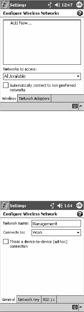
Windows Mobile 2003—Chapter 2
107700 Series Color Mobile Computer User’s Manual
2Tap the Advanced tab > Network Card >theWireless tab > Add New
... .
3Tap the General tab, then enter a network name. If the network was
detected, the network name is entered and cannot be changed.
From Connects to, select to what your network is to connect. If you
select “Work,” you can do a vpn connection or use proxy servers. If you
select “The Internet,” you can connect directly to the internet.
To connect to an ad-hoc connection, select This is a device-to-device
(ad-hoc) connection.
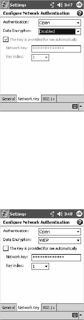
Windows Mobile 2003Chapter —2
108 700 Series Color Mobile Computer User’s Manual
4Tap the Network Key tab, then do the following:
To Disable Authentication
aSet Authentication to either “Open” if WEP keys are not required;
or “Shared” when WEP keys are required for association.
bSet Data Encryption to “Disabled.”
To Enable WEP Encryption
aSet Authentication to either “Open” if WEP keys are not required;
or “Shared” when WEP keys are required for association.
bSet Data Encryption to “WEP.”
cTo change the network key, clear The Key is provided for me auto-
matically box, then enter the new Network key and select the ap-
propriate Key index.
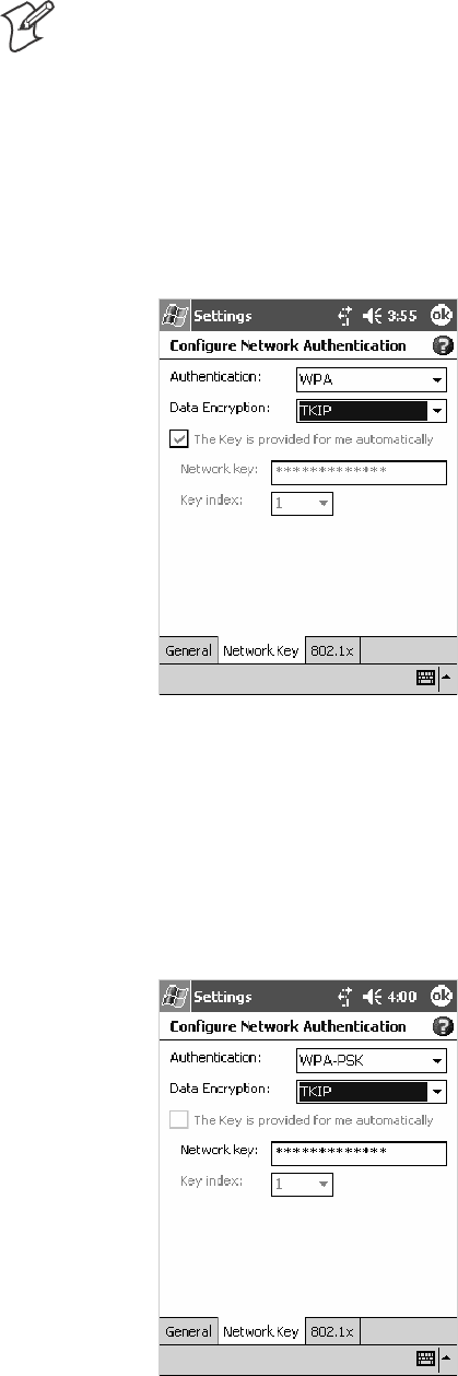
Windows Mobile 2003—Chapter 2
109700 Series Color Mobile Computer User’s Manual
Note: The following information applies when you have Enable
Microsoft’s Wireless Zero Config checked via the Wireless Network
control panel applet (see Appendix A, “Configurable Settings”).
To Enable WPA Authentication (730, 751, 751, 761 Computers)
aSet Authentication to “WPA.” See page 364 for information about
WPA encryption.
bSet Data Encryption to either “WEP” or “TKIP.” See page 364 for
information about WEP and TKIP encryption.
To Enable WPA Authentication Using a Preshared Key (730, 741, 751, 761 Computers)
aSet Authentication to “WPA-PSK.” See page 364 for information
about WPA encryption.
bSet Data Encryption to either “WEP” or “TKIP.” See page 364 for
information about WEP and TKIP encryption.
cEnter the new Network key.
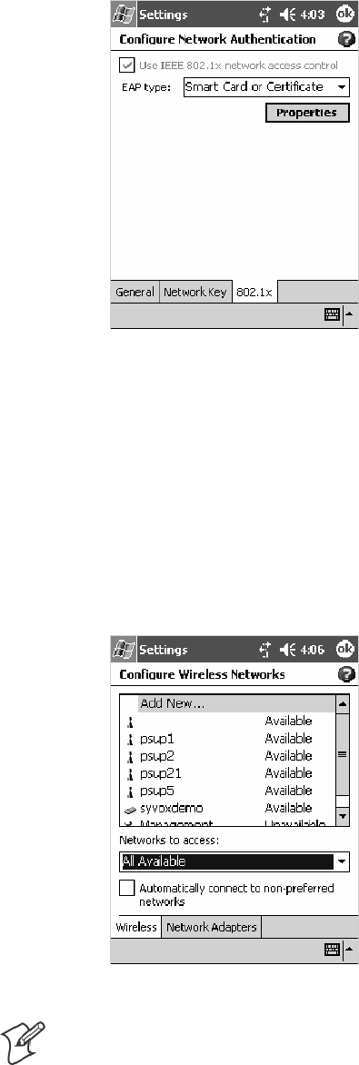
Windows Mobile 2003Chapter —2
110 700 Series Color Mobile Computer User’s Manual
5Tap the 802.1x tab, select either “PEAP” or “Smart Card or Certificate”
for the EAP type,thentapProperties to adjust its settings.
6Tap ok to return to the Configure Wireless Network screen.
7From the Networks to access drop-down list, select “All Available,”
“Only access points,” or “Only computer-to-computer” depending on
thetypeofnetworkstowhichyouconnect.
To connect only to networks you have already configured, clear Auto-
matically connect to non-preferred networks.
Tap ok to close this screen.
Note: If you select to automatically connect to non-preferred networks,
your device detects any new networks and provide you the opportunity to
configure them.
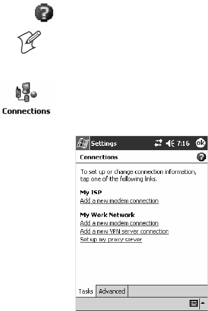
Windows Mobile 2003—Chapter 2
111700 Series Color Mobile Computer User’s Manual
Creating a VPN Server Connection to Work
A VPN connection helps you to securely connect to servers, such as a cor-
porate network, via the Internet. Ask your network administrator for the
following:
SUser name
SPassword
SDomain name
STCP/IP settings
SHost name or IP address of the VPN server
To view additional information for any screen in the wizard or while
changing settings, tap the Help icon.
Note: To change existing settings in My Work Network, tap Manage
existing connections >theVPN tab. Select the desired VPN connection,
tap Settings, and follow the instructions on the screen.
1Tap Start >Settings >theConnections tab>theConnections icon.
Tap Add a new VPN server connection beneath My Work Network to
initiate this procedure.
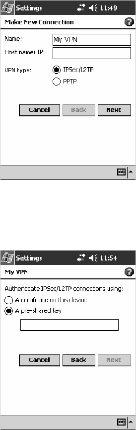
Windows Mobile 2003Chapter —2
112 700 Series Color Mobile Computer User’s Manual
2In Name, enter a name for the connection, such as a company’s name.
In Host name/ IP, enter the VPN server name or IP address.
Next to VPN type, select the type of authentication to use with your
device: “IPSec/L2TP” or “PPTP.” If you are not sure which option to
choose, ask your network administrator.
Tap Next to continue.
3Selectthetypeofauthentication.IfyouselectA pre-shared key,enter
the key provided by your network administrator.
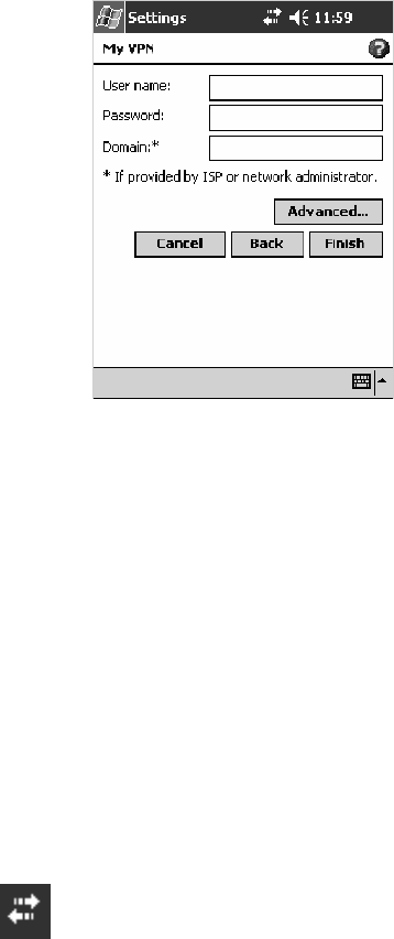
Windows Mobile 2003—Chapter 2
113700 Series Color Mobile Computer User’s Manual
4Enter your user name, password, and domain name as provided by your
ISP or network administrator. If a domain name was not provided, try
the connection without entering a domain name.
5You should not need to change any Advanced settings. Instances where
you must change advanced settings include:
SThe server to which you are connecting does not use dynamically-as-
signed addresses, and you need to enter your TCP/IP settings.
SYou need to change server DNS or WINS settings.
To change advanced settings, tap Advanced.Otherwise,tapFinish.
Insert necessary equipment, such as a network (Ethernet) card, into the
device, and use a desired program to automatically begin connecting. For
example, switch to Pocket Internet Explorer and browse to a Web page.
Ending a Connection
To disconnect, do one of the following:
SWhen connected via modem or VPN, tap the Connectivity icon on the
navigation bar, and then tap Disconnect.
SWhen connected via cable or cradle, detach your device.
SWhen connected via Infrared, move the device away from the other
computer or device.
SWhen connected via a wireless network, switch off the connection.

Windows Mobile 2003Chapter —2
114 700 Series Color Mobile Computer User’s Manual
Connecting Directly to an E-mail Server
You can set up a connection to an e-mail server so that you can send and
receive e-mail messages by using a modem or network connection and In-
box on your 700 Color Computer.
Note: The ISP or network must use a POP3 or IMAP4 e-mail server and
an SMTP gateway.
You can use multiple e-mail services to receive your messages. For each
e-mail service you intend to use, first set up and name the e-mail service. If
you use the same service to connect to different mailboxes, set up and
name each mailbox connection.
Setting Up an E-mail Account
Do the following to set up an e-mail service. Tap the question mark at the
top of the screen for more assistance.
1On your 700 Color Computer, tap Start >Inbox to access the Inbox
application. Tap Accounts >New Account.
2Enter an e-mail address, tap Next,Cancel,thenNext after the status of
the automatic configuration is listed as “Completed.”
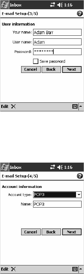
Windows Mobile 2003—Chapter 2
115700 Series Color Mobile Computer User’s Manual
3Enter the Your name and Password information, then tap Next.
4Select the appropriate service type from the Account type drop-down
list, either “POP3” or “IMAP4,” or enter a new account type, then tap
Next.
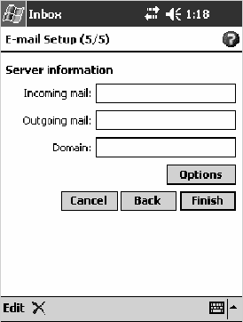
Windows Mobile 2003Chapter —2
116 700 Series Color Mobile Computer User’s Manual
5In Incoming mail,enterthenameofyoure-mailserver.InOutgoing
mail,enterthenameofyourSimpleMailTransferProtocol(SMTP)
host. If you are using a network connection, enter your domain name in
Domain.TapOptions to do additional configurations. Tap Finish to
assign this service.
When finished, to connect to your e-mail server, from the Inbox applica-
tion, tap Accounts >Connect. For more information on using the Inbox
application, see “Inbox: Sending and Receiving E-mail Messages”onpage73.

117700 Series Color Mobile Computer User’s Manual
Installing Applications
3
There are multiple ways to get an application to your 700 Series Color
Mobile Computer; just as there are multiple ways to package the applica-
tion for delivery.
Note: “700 Color” pertains to 740, 741, 750, 751, 760, and 761 Com-
puters unless otherwise noted.

Installing ApplicationsChapter —3
118 700 Series Color Mobile Computer User’s Manual
Packaging an Application
Useanyofthesemethodstopackageanapplicationforinstallation:
SFor very simple applications, the application itself might be the only file
that needs to be delivered.
SIt could be a directory structure that contains the application, support-
ing files like ActiveX controls, DLLs, images, sound files, and data files.
SOr, you could package an application via a CAB file.
Consider any of the following when choosing a location into which to
store your application:
SIn the basic 700 Color Computer, there are two built-in storage op-
tions: the Object Store and the Persistent Storage Manager (PSM). The
Object Store is RAM that looks like a disk. Anything copied here is de-
leted when a cold-boot is performed on the 700 Color Computer. The
PSMisanareaofstoragewhichisembeddedinasectionofthesystem’s
FLASH memory. This storage area is not erased during a cold-boot. It
may, however, be erased during the reflashing process. In addition to
storing applications and data files, you do have the option to store a per-
sistent registry to the PSM region.
SIf the optional Secure Digital or CompactFlash storage card is in the
system, then consider this card the primary location for placing an ap-
plications install files. The following folders represent either card:
SThe Secure Digital storage card creates the “\SDMMC Disk” folder.
SThe CompactFlash storage card creates the “\Storage Card” folder.
Note: The 730 Mobile Computer does not support the Compact
Flash storage card.
SUse the small non-volatile Flash File Store region to hold CAB files that
rebuild the system at cold-boot or install applications from a CAB file
into the Flash File Store so they are ”ready-to-run” when a cold-boot is
performed. Since the FLASH in the system has a limited number of
write cycles, do not use the Flash File Store for excessive writing pur-
poses; however, reading is okay.
Files copied to any of these locations are safe when a cold-boot is
performed on a 700 Color Computer — providing the AutoRun system is
installed in the appropriate location You can find this system in the 700
Color Management Tools portion of the Intermec Developer’s Library CD.
Copying a CAB file to the “\CABFILES” folder on one of these cards
automatically extracts that CAB file on every cold-boot to ensure that your
system is properly set up (see page 124).
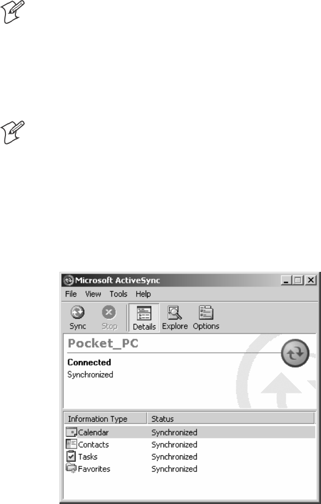
Installing Applications—Chapter 3
119700 Series Color Mobile Computer User’s Manual
Installing Applications
Consider any of the following options to get the package to the preferred
location on your 700 Series Computer.
SMicrosoft ActiveSync
SFTP Server (page 120)
SSecure Digital or CompactFlash storage cards (page 120)
Using Microsoft ActiveSync
Note: These instructions assume the 700 Color Management Tools por-
tion of the Intermec Developer’s Library CD was installed on your desktop.
The Microsoft ActiveSync tool is located on the 700 Color Companion CD.
See Chapter 2, “Windows Mobile 2003,” for information about this tool as
provided by Microsoft Corporation.
This can be a serial, USB, Ethernet, InfraRed, or 802.11b ActiveSync con-
nection. Files can be copied using File Explorer on a desktop or a laptop
computer. This is usually good when updating few 700 Color Computers.
Note: The 730 Computer does not support Ethernet.
These instructions assume that Microsoft ActiveSync was installed onto
your desktop and is up and running. If not, go to Chapter 2, “Windows
Mobile 2003,” for an URL from which to download the latest application.
1Connectyour700ColorComputertoyourdesktopcomputerviaan
ActiveSync cable or IrDA.
2Wait for a “Connected” message to appear in the Microsoft ActiveSync
application to signal a connection to the 700 Series Computer. If neces-
sary, select File >Get Connected to initiate a connection.

Installing ApplicationsChapter —3
120 700 Series Color Mobile Computer User’s Manual
3Click Explore toaccesstheMobileDevicefolderonyourunit.
4From your desktop, select Start >Windows Explorer, then browse the
“C:\Intermec\700C Mgmt Tools\CabFiles” path for any CAB files
needed for your 700 Color Computer. Select the appropriate file, right-
click the file for a pop-up menu, then select Copy.
5Within the Mobile Device directory, go to the directory where you
want the files located on the 700 Color Computer, do a right-click for a
pop-up menu, then select Paste.
6When all of the files are pasted, perform a warm-boot on the 700 Color
Computer. When the computer reboots, wait for the LED on the top
left of your keypad to stop blinking. Tap Start >Programs >File
Explorer to locate the newly copied executable files, then tap these files
to activate their utilities.
Using the FTP Server
The 700 Color Computer has a built-in FTP Server that connects to a net-
work via Ethernet, 802.11b, or WAN (Wireless Access Network). This
allows connections to the 700 Color Computer to perform file transfers or
computer management functions. Another benefit is you can create FTP
scripts to automate the process of copying files to the 700 Color Comput-
er.Thisoptionisgoodforwhenalargenumberof700ColorComputers
need updating. See Chapter 7, “Programming,” for more information.
Using a Storage Card
Use the following steps to install an application using a storage card:
Copying to a CompactFlash Card
Note: These instructions do not apply to the 730 Computer.
1Suspendthe700ColorComputerandremoveitsCompactFlashdrive,
which holds a SanDisk CompactFlash storage card.
2Using a CompactFlash Adapter card, place the CompactFlash drive in
your desktop PC card drive.
3Create a subdirectory on the PCMCIA CompactFlash drive in which to
store your application.
4Use the CEImager application to add the autorun system to the storage
card. See the Software Tools User’s Manual to learn about CEImager.
5Copy your application, data files, and all required DLLs and drivers to
the subdirectory created on the CompactFlash drive.
6Add your application to the AUTOUSER.DAT file on the
“\Storage Card\2577” directory with the following statement:
RUN=\<your directory>\<yourapp.exe>
where your directory is the directory on the CompactFlash storage card
where the application was installed, and yourapp.exe isthenameofyour
application. Finish the “RUN=” statement with a carriage return line-
feed combination. There may be multiple run statements in the file.
Installing Applications—Chapter 3
121700 Series Color Mobile Computer User’s Manual
7Remove the CompactFlash card from your desktop and reinstall it into
the 700 Color Computer.
8Warm-boot the 700 Color Computer to add these files to the Compact-
Flash storage card.
If the AUTOUSER.DAT file is found and the “RUN=” statement is cor-
rect, the task manager launches and executes your program on startup.
Copying to a Secure Digital Storage Card
1Suspend the 700 Color Computer and remove its Secure Digital drive,
which holds a Secure Digital storage card.
2Using a Secure Digital Adapter card, place the Secure Digital drive in
your desktop PC card drive.
3Create a subdirectory on the PCMCIA Secure Digital drive in which to
store your application.
4Use the CEImager application to add the autorun system to the storage
card. See the Software Tools User’s Manual to learn about CEImager.
5Copy your application, data files, and all required DLLs and drivers to
thesubdirectorycreatedontheSecureDigitaldrive.
6Add your application to the AUTOUSER.DAT file on the
“\SDMMC Disk\2577” directory with the following statement:
RUN=\<your directory>\<yourapp.exe>
where your directory is the directory on the Secure Digital storage card
where the application was installed, and yourapp.exe isthenameofyour
application. Finish the “RUN=” statement with a carriage return line-
feed combination. There may be multiple run statements in the file.
7Remove the Secure Digital card from your desktop and reinstall it into
the 700 Color Computer.
8Warm-boot the 700 Color Computer to add these files to the Secure
Digital storage card.
If the AUTOUSER.DAT file is found and the “RUN=” statement is cor-
rect, the task manager launches and executes your program on startup.
Updating the System Software
You can use the Intermec Recovery CD to reinstall or update the operating
system software on the 700 Color Computer. For more information, con-
tact your Intermec representative.
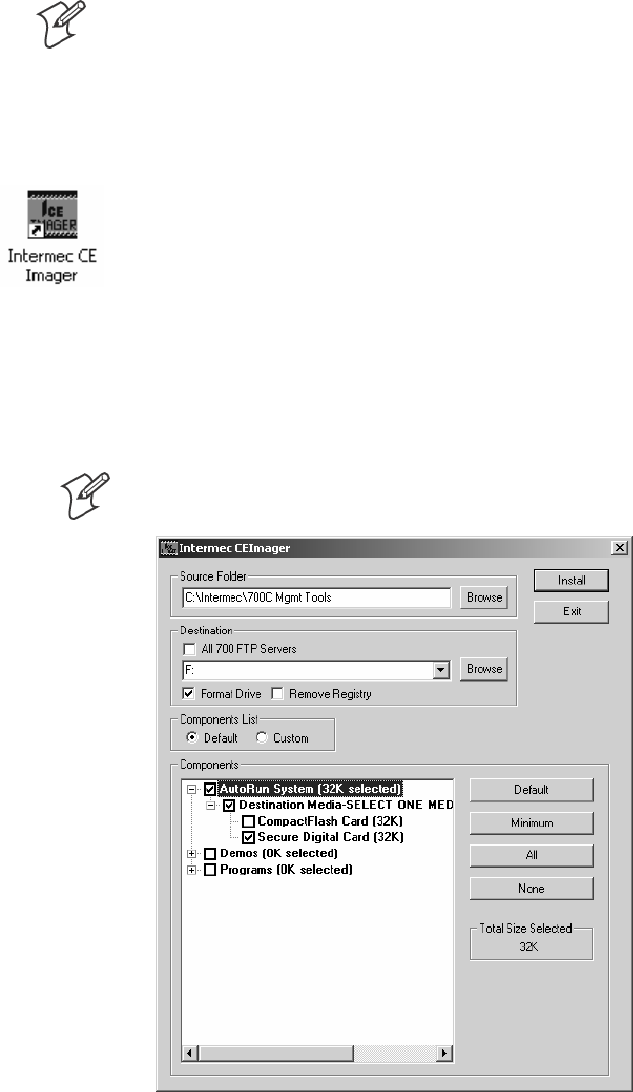
Installing ApplicationsChapter —3
122 700 Series Color Mobile Computer User’s Manual
Migrating Applications
Note: These instructions assume that the 700 Color Management Tools
portion of the Intermec Developer’s Library CD was installed on your desk-
top and that a storage card was added to the base configuration of the 700
Color Computer.
Do the following required stepstoensurethatCABfilesarerestored,ap-
plications automatically start, and registry is restored on cold-boot:
1From your desktop, double-click the Intermec CE Imager desktop icon
to access the Intermec CEImager application. If this icon is not on your
desktop, then double-click the CEIMAGER.EXE executable from the
“C:\Intermec\700C Mgmt Tools\Tools\CEImager” folder.
2Click Default under Components List to activate the components.
3Click (+) to expand the AutoRun System component, click (+) to ex-
pand the Destination Media option, then select either the
CompactFlash Card option or the Secure Digital Card option. Do not
select both storage cards, as the AutoRun files copied will work for one stor-
age card, but not work on the other storage card.
Note: The 730 Computer does not support CompactFlash storage cards.
4Click Install to install the AUTORUN files onto the storage card.
5Create a “\CabFiles” folder on the storage card. Copy any CAB files that
are to be extracted on every startup into this folder.
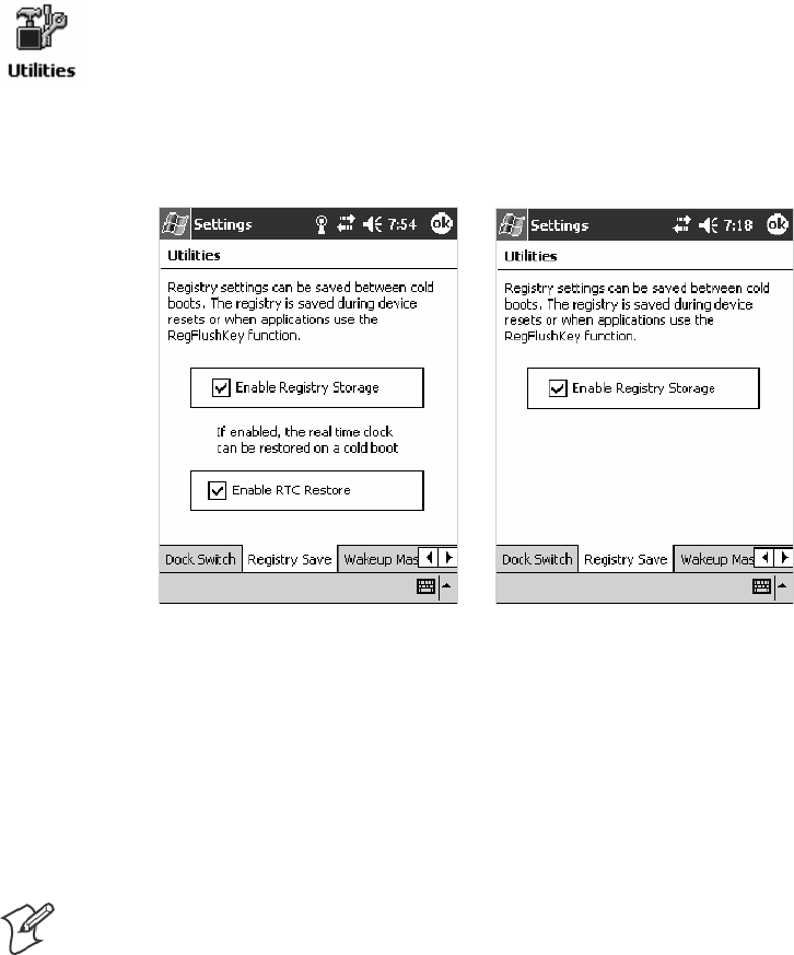
Installing Applications—Chapter 3
123700 Series Color Mobile Computer User’s Manual
6In the “\2577” directory, add your custom AUTOUSER.DAT file. See
the Recovery Help for more information on how to set up an
AUTOUSER.DAT file.
7If you are using the RegFlushKey() API, the application must use a spe-
cial API to make sure the registry is written to the appropriate card; or
you can use the Utilities control panel applet, as follows. See Appendix
A, “Configurable Settings,” for more information about this applet.
aFrom the 700 Series Computer, tap Start >Settings >theSystem tab
>theUtilities icon > the Registry Save tab.
bTap Enable Registry Storage to save the registry in the Flash File Sys-
tem (PSM) via the “\Flash_File_Store\Registry” path.
cTap ok to save your entry and exit the Utilities control panel applet.
700 Color Screen 730 Screen
8Remove the storage card from the desktop PC and install the card into
the 700 Series Computer.
9Perform a cold-boot on the 700 Series Computer. Files automatically
install from the storage card upon reboot. Any calls to the
RegFlushKey() API automatically writes the registry to the appropriate
location.
Note: Both the warm-boot and the cold-boot procedures, via the software
API, will also flush the registry.
Installing ApplicationsChapter —3
124 700 Series Color Mobile Computer User’s Manual
Migrating from a 700 Monochrome Computer
As you migrate from a 700 Monochrome Computer to a 700 Color Com-
puter, you need to consider the following: When converting a 700 Mono-
chrome Computer application to run on the 700 Color Computer, most
APIs should work without changes. Below are a few exceptions:
SThe 700 Monochrome Computer uses the “\Storage Card” folder for
nonvolatile storage. You may need to change the application to store
data onto the “SDMMC Disk” folder instead of the “\Storage Card”
folder if a Secure Digital storage card is present in the system.
SIf the application uses the RegFlushKey() API, it must first verify that
the proper media is available in the system and call the special API men-
tioned in Step 7 on the previous page.
SIftheapplicationisusingthe700Colorswitchabledock,usethe
IOCTL_DOCK_SWITCH value from the
IOCTL_HAL_ITC_WRITE_SYSPARM function to set the proper
port on the dock before communications. See more information about
this KernelIOControl function in Chapter 7, “Programming.”
SSome WAN radio options have changed. Review the WAN radio infor-
mation in Chapter 4, “Network Support,“to determine if any changes are
required in your application.
SArrow and tab keys are reversed from the 700 Monochrome Computer.
Keyboard remapping is available on the 700 Color Computer should
you need to map these keys like that of the 700 Monochrome Comput-
er (see page 121).
SSpecial SDKs are not needed to compile applications for the Xscale pro-
cessor. Targeting the SA1110 processor creates applications that run on
the 700 Color Computer.
Installing Cabinet Files
CAB files (short form of “cabinet” files) are compressed folders as defined by
Microsoft. A “cabinet” file is a single file, usually suffixed with .CAB, that
stores compressed files in a file library. A compressed file can be spread
over several cabinet files. During installation, the setup application decom-
presses the files stored in a cabinet and copies them to the user’s system.
For the 700 Series Computer, CAB files register DLLs, create shortcuts,
modify registry entries, and run custom setup programs. Tap a CAB file to
extract that file or place the CAB file on one of the approved storage de-
vices in the “\CabFiles” folder, then perform a warm-boot on the 700 Se-
ries Computer. There are two methods available to extract a CAB file:
STap a CAB file to extract it. With this method, the CAB file is automat-
ically deleted when the extraction process is successful, unless the CAB
file is set with the read-only attribute.
SUse the AUTOCAB method to extract all files when a cold-boot is per-
formed on the 700 Series Computer. This method is on the Intermec
Developer’s Library CD,seeitsSoftware Tools User’s Manual for informa-
tion.

125700 Series Color Mobile Computer User’s Manual
Network Support
4
The 700 Series Color Mobile Computer can integrate up to three radios in
a single unit, and automatically installs the appropriate software for radio
or phone use when the unit is powered on.
Note: “700 Color” pertains to 740, 741, 750, 751, 760, and 761 Com-
puters unless otherwise noted.

Network SupportChapter —4
126 700 Series Color Mobile Computer User’s Manual
Understanding Your 700 Series Computer
Due to the number of 700 Series Computers now available, and to the
number of applications, drivers, and modules that may or may not be
available, these tables are to help you determine what is on your particular
computer.
Hardware Features
730 Computers 802.11b radio, Bluetooth
740 Computers Ethernet, Bluetooth
741 Computers Ethernet, Bluetooth
750 Computers Ethernet, 802.11b radios, Bluetooth
751 Computers Ethernet, 802.11b/g radios, Bluetooth
760 Computers Ethernet, 802.11b, CDMA/1xRTT WAN (data only*), GSM/GPRS WAN (data and voice)
radios, Bluetooth
761 Computers Ethernet, 802.11b/g, CDMA/1xRTT WAN (data and voice), GSM/GPRS WAN (data and
voice) radios, Bluetooth
*ThisisforunitssoldintheUnitedStates.
Software Applications
Computers: 730 740 741 750 751 760 761
CORE (page 132) XXXXXXX*
Microsoft Phone for CDMA Radios (page 140) X
Microsoft Phone for GSM Radios (page 149) X
On-board Wired Ethernet (page 128) XXXXXX
PhoneUtility (page 154) X
SB555 Watcher (page 157) X
Wireless Local Area Network (page 129) X XXXX
Wireless Personal Area Network (page 182) XXXXXXX
Wireless Wide Area Network XX
WWAN Communicator** X X
WWAN Toolkit XX
* Does not apply to WAN radios
** See the “WWAN Communicator User’s Guide” P/N: 074250.
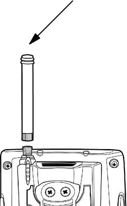
Network Support—Chapter 4
127700 Series Color Mobile Computer User’s Manual
Antennas (760/761 Computers)
The 760 Computers have color-coded tips to identify the WWAN radio
type within. Below are the colors and their types. The 761 Computers in
the United States and Canada use the external antenna with no color in its
tip. See your Intermec representative for more information.
SRed (760 Computers)
CDMA (non-Sprint networks) and GSM/GPRS US/Canada
SWhite (760 Computers)
GSM/GPRS US/Canada and CDMA Sprint networks
SBlue (760/761 Computers)
GSM/GPRS International (MC45 WAN radios)
SNo Color (761 Computers)
CDMA and GSM/GPRS US/Canada (MC46 WAN radios)
Network Adapters
Your 700 Color Computer can have up to three radios installed. The de-
fault network adapter or radio is dependent on what radios are installed in
your 700 Color Computer.
With the boot menu, you can specify “802.11,” “Ethernet,” or “No Net-
working” to load onto your 700 Color Computer when a cold-boot is per-
formed. When a warm boot is performed, the 700 Color Computer loads
the network set just prior to the warm boot.
The 730 Computer only has the 802.11b radio and wireless printing. It
does not have an external antenna. Other radios are not supported. See the
Developer’s Support web site for the latest information on network adapt-
ers for your unit.
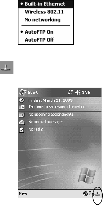
Network SupportChapter —4
128 700 Series Color Mobile Computer User’s Manual
Ethernet Communications (740, 741, 750, 751, 760, 761 Computers)
Follow the steps below to start Ethernet communications on the 700 Color
Computer. If your system does not contain an 802.11b or 802.11b/g
radio, then Ethernet networking using DHCP is selected as the default.
When “Built-in Ethernet” is selected from the NDISTRAY pop-up menu
(the Network Driver Interface Specification tray application),
then the Ethernet icon shown to the left appears in the System Tray as
circled in the following illustration.
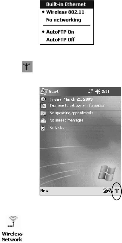
Network Support—Chapter 4
129700 Series Color Mobile Computer User’s Manual
Wireless 802.11 Communications
When “Wireless 802.11” is selected via the NDISTRAY pop-up menu:
the Wireless 802.11 antenna icon shown to the left appears in the system
tray as circled in the following illustration.
To configure wireless 802.11 communications on the 700 Color
Computer, tap Start >Settings >theSystem tab>theWireless Network
icon to access the Profile Wizard for the 802.11b or 802.11b/g radio
module.GotoAppendixA,“Configurable Settings,” for configuration
information.
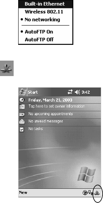
Network SupportChapter —4
130 700 Series Color Mobile Computer User’s Manual
No Networking
When “No networking” is selected from the NDISTRAY pop-up menu:
the disconnected icon shown to the left appears in the system tray as
circled in the following illustration.
Network Selection APIs
The Network Selection APIs change the network adapter configuration
programmatically. Both drivers support the same IOCTL function num-
bers for loading and unloading the drivers. Go to Chapter 7, “Program-
ming,” to see the APIs.
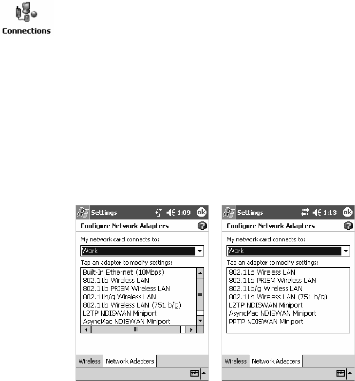
Network Support—Chapter 4
131700 Series Color Mobile Computer User’s Manual
Network Connections
From the 700 Color Computer, tap Start >Settings >theConnections
tab > Connections >theAdvanced tab > Network Card or the Network
Adapters tab to access the network connections for this unit. Make the
changes necessary for your network, then tap ok when finished. Consider
the following before making your selection:
SFor a work connection or an internet connection, select the “Built-In
Ethernet (10 Mbps)” option.
SThe “802.11b Wireless LAN” option is for 750 and 760 Computers
with legacy 802.11b radios.
SThe “802.11b PRISM Wireless LAN” option is for 750 and 760 Com-
puters with standard 802.11b radios.
SThe “802.11b/g Wireless LAN” option is for 751 and 761 Computers
with the latest 802.11b/g radios.
700 Color Screen 730 Screen

Network SupportChapter —4
132 700 Series Color Mobile Computer User’s Manual
CORE (760, 761 Computers with WAN Radios)
The Intermec CORE application provides a framework for various mod-
ules that let you configure and manage your Intermec products. If a mod-
uleisnotyetusedorset,COREdefaultstothefirstmoduleaslistedal-
phabetically.
These modules are software plug-ins that can be configuration tools, such
as the 802.11b or 802.11b/g radio configuration module, or they can pro-
vide information on your environment, such as a battery life module.
CORE modules are collections of specific information. Each module can
display general and detailed information. Tap the General and Details tabs
near the bottom to switch between general and detailed information. Note
that not all modules have detailed information.
Activating CORE
CORE is built into the operating system of every 760 or 761 Computer.
To run CORE for the first time, select Start >Programs >File Explorer,
select “\Flash File Store\Apps\CORE,” then tap the CORE executable file.
After CORE is run on the 760 or 761 Computer, tap Start >Programs >
Core to access this application henceforth.
Note: To deactivate CORE, tap CORE >Exit from within the CORE
application.
Install an Available Radio Module
To install an available radio module onto your 760 or 761 Computer, tap
Modules >Add/Remove, select a module from the bottom Available box,
then tap Add to put the selected module in the upper Installed box. Click
OK to exit the Add/Remove Modules screen.
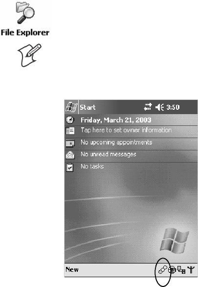
Network Support—Chapter 4
133700 Series Color Mobile Computer User’s Manual
Loading a Radio Module
To load or switch to another radio module installed on the 760 or 761
Computer, tap Modules >Choose Module, select a module from the
Installed Modules box, then tap Choose to initialize and begin using that
module.
To learn more about this application, see its online help. Tap Start >
Programs >File Explorer and select “\Flash File Store\Apps\CORE,” then
tap the corehelp .HTM file.
Note: Once CORE is running, you can return to it by tapping its icon
from the System Tray via the Today screen. Tap Start >Today >theCore
three-ring icon (circled in the following illustration).
802.11 CF CORE Module
The 802.11 CF CORE module displays helpful information about the
802.11b or 802.11b/g radio option built into your 760 or 761 Computer.
Note that you can configure the 802.11b or 802.11b/g radio module from
this CORE application. Select Configure >Configure Intermec 802.11
CF from the bottom menu bar to access the Profile Wizard application.
See Appendix A, “Configurable Settings,” for information about this ap-
plication via the Wireless Network control panel applet.
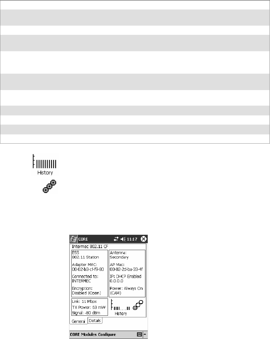
Network SupportChapter —4
134 700 Series Color Mobile Computer User’s Manual
General
Below are descriptions and meanings for each piece of information pro-
vided via the General tab. Note that the information is listed alphabetically.
Adapter MAC Identifies the MAC address for this 802.11b or 802.11b/g adapter.
Antenna Identifies the antenna used with the 802.11b or 802.11b/g radio: “Primary,” “Secondary,” or “Di-
versity.”
AP Mac Identifies the MAC address of the access point to which this 760 Computer is connected.
Connected to
or Scanning...
Reports the connection status and to which SSID this 760 Computer is attached.
Encryption or
Keys Absent
“Encryption” reports the encryption mode and the association mode (in parentheses). See page 367
for information about WEP encryption. “Keys Absent” reports the association mode in parentheses.
See page 367 for information about WPA encryption.
ESS Identifies the type of network to which you are attached, either an ESS (Extended Service Set)
802.11 Station, or Ad-hoc.
IP Provides the IP address which can be set as either DHCP (Dynamic Host Configuration Protocol)
or statically.
Link Indicates the speed at which a connection is made, the data rate of the last transmitted packet.
Power Indicates the power status of this 802.11b profile, such as “CAM,” “Auto,” or “PSP.”
Signal Identifies the radio signal strength (in dBm) of signals coming from an access point.
TX Power Shows the transmit power (in milliwatts) at which transmissions are made.
History:
This bar graph displays an active history of this radio module’s quality of
connections.
Friendly Indicator:
This indicates the general quality of the 802.11b or 802.11b/g connection.
Three filled dots indicates the best quality; two filled dots dictates good
quality; one filled dot is of fair quality; and when all three dots are empty,
the quality is considered poor. When this icon appears with a red line, the
radio is disconnected or nearly so from the access point.
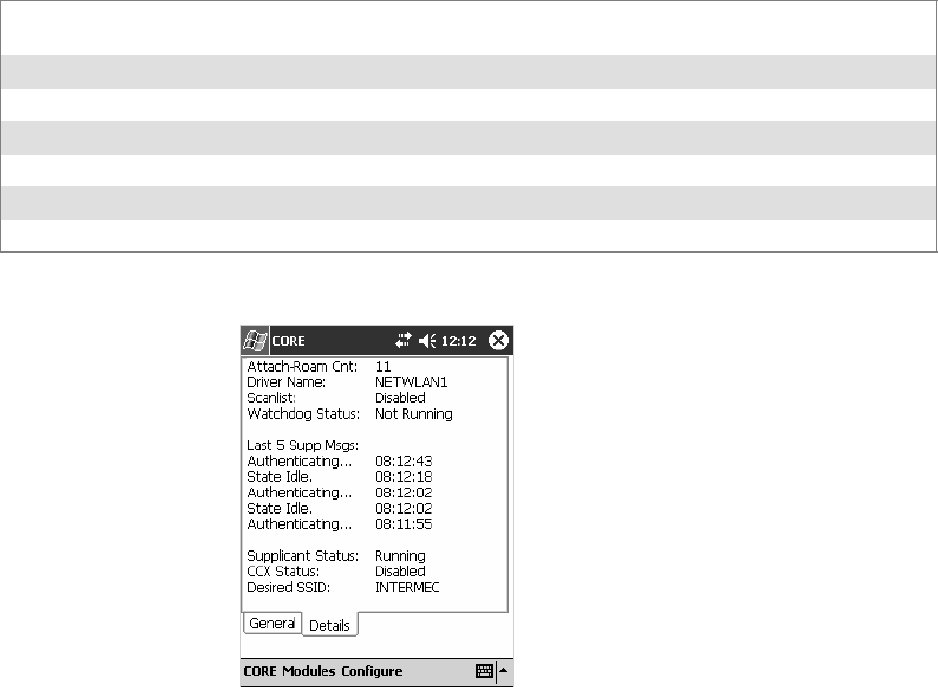
Network Support—Chapter 4
135700 Series Color Mobile Computer User’s Manual
Details
Below are descriptions and meanings for each piece of information pro-
vided via the Details tab. Note the information is listed alphabetically.
Attach-Roam Cnt Includes the number of new associations made during the current session, due to roaming. The
number is reset on suspend/resume cycles.
CCX Status States the status of the CCX features, either enabled or disabled.
Desired SSID Identifies the preferred Service Set Identifier (SSID).
Driver Name Identifies the 802.11b or 802.11b/g driver installed on this 700 Color Computer.
Last 5 Supp Msgs Monitors and reports the 802.11 Security Supplicant activity.
Scanlist Indicates whether the Scan List option was enabled or disabled.
Supplicant Status Monitors the 802.11 security activity on the client: “Running” or “Stopped.”
CDMA/1xRTT CORE Module (760 Computers with WAN Radios)
Code Division Multiple Access (CDMA) is a form of wide area wireless
communications. 1XRTT supports up to 144 KB per second packet data
transmission.
The WAN radio CORE module displays helpful information about the
CDMA/1xRTT radio option built into your 760 Computer.
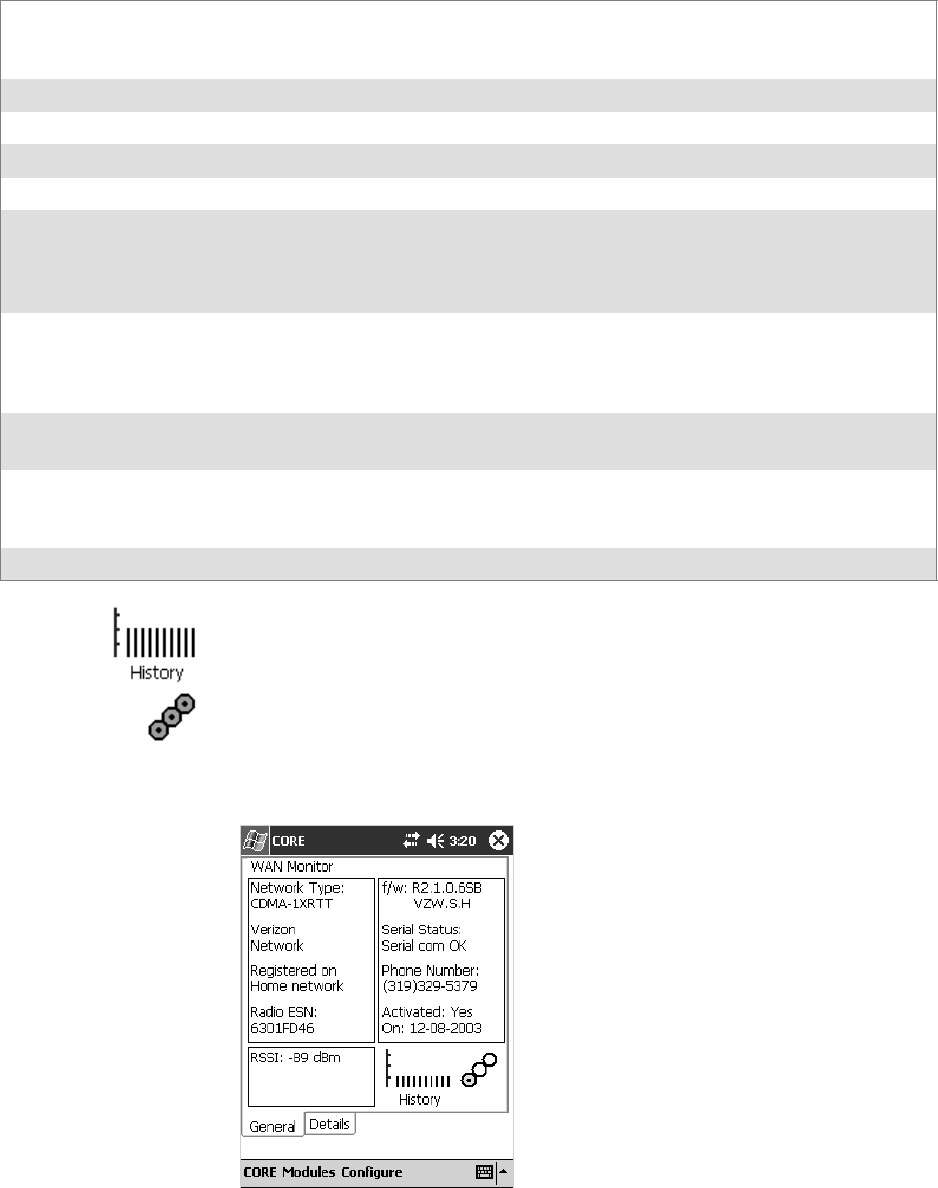
Network SupportChapter —4
136 700 Series Color Mobile Computer User’s Manual
WAN Monitor — General
Below are descriptions and meanings for each piece of information pro-
vided via the General tab. Note that the information is listed alphabetically.
Activated Indicates whether the ESN on this unit was ever activated. Note: this activation indicates that the
device was activated at some point in time. However, it does not guarantee that the activation is valid
or is working on the carrier’s network.
f/w Identifies the firmware version, if available.
Network Type The network type which would list “CDMA-1XRTT.”
On Indicates when activation was provided by your service provider.
Phone Number Identifies the telephone number (or MDN) assigned to the WAN Module installed in your unit.
Radio ESN Lists the Electronic Serial Number (ESN) assigned to this radio module or “Unavailable” if a
number cannot be read from the radio. This number is required for activation. You must provide
this number to your service provider, such as Sprint, Verizon, Bell Mobility, etc., for activation.
Note a decimal version of your ESN is on the Details page.
Registered on
home network
If the WAN radio module is registered with a service provider network, one of these appears:
SRegistered on home network: Radio module is registered on its “home” network.
SRegistered on roamed network: Radio module registered on another service provider’s network.
SRadio Not Registered: There is no network within range of this radio module.
RSSI Displays the Received Signal Strength Indicator (RSSI) frequency or lists “Unavailable” if there
is no signal or the signal cannot be retrieved from the radio module.
Serial Status Indicates whether serial communications passed (“Serial com OK”) or failed (“Serial com FAIL”)
in its last transaction. A status of “Serial com FAIL” typically indicates that the 760 Computer is
unable to establish communication with the radio module installed within.
Verizon Network Identifies your network service provider.
History:
This bar graph displays an active history of this radio module’s quality of
connections.
Friendly Indicator:
Usually indicates the signal strength for this radio module. Three filled
dots indicate a high quality or strong signal. Three empty dots indicate
that the signal is out of range or there is no signal detected.
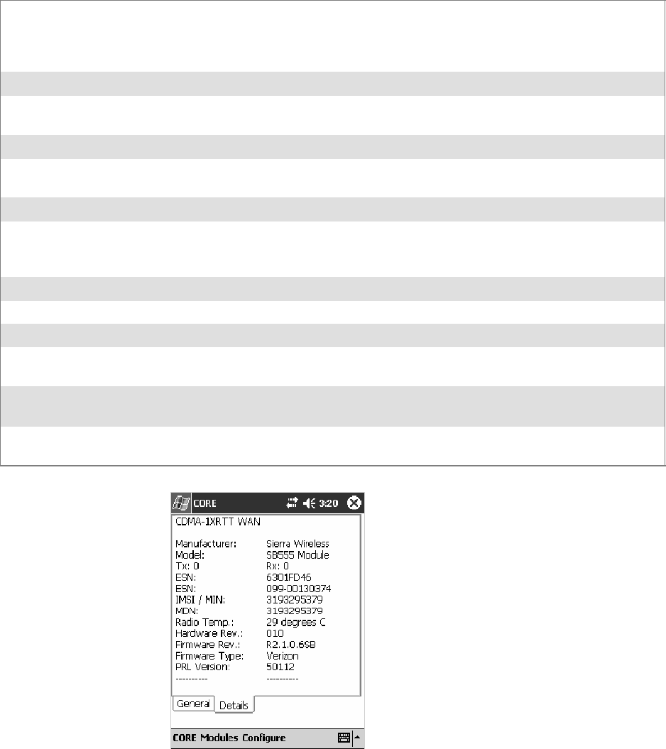
Network Support—Chapter 4
137700 Series Color Mobile Computer User’s Manual
WAN Monitor — Details
Below are descriptions and meanings for each piece of information pro-
vided via the Details tab. Most of this is similar to what is shown under
the General tab. Note that the information is listed alphabetically.
ESN Lists the Electronic Serial Number (ESN) assigned to this radio module or “Unavailable” if a num-
ber cannot be read from the radio. This number is required for activation. You must provide this
number to your service provider, such as Sprint, Verizon, Bell Mobility, etc., for activation. Note
that both the hex version and the decimal version of your ESN is provided.
Firmware Rev Identifies the firmware version, if available.
Firmware Type Identifies the type of firmware installed in the WAN radio module. It should match the carrier
you are using as your network provider.
Hardware Rev Identifies the hardware revision of the WAN radio module installed in your unit.
IMSI/MIN Shows the IMSI (International Mobile Subscriber Identity) number assigned to the Subscriber
Identity Module (SIM) card installed in this 760 Computer.
Manufacturer Lists the name of the manufacturer that developed this radio module, such as “Sierra Wireless.”
MDN Shows the MDN (Mobile Directory Number) or DN (Directory Number) — the number that
identifies the account tied to your device. You can consider this the “phone number.” Note that
the MDN and IMSI/MIN numbers can be the same.
Model Lists the product name for this radio module, such as “Model 72.”
Phone Number Identifies the telephone assigned to the WAN radio module.
PRI Version Provides the version number of the Preferred Roaming List (PRL).
Radio Temp Identifies the temperature of the radio module, or lists “Unavailable degrees” if no information or
temperaturecannotbemeasured.
Rx (abbreviation for receive) Indicates the number of bytes received over the WAN connection since
the CORE WAN Module was started.
Tx (abbreviation for transmit) Indicates the number of bytes received over the WAN connection since
the CORE WAN Module was started.

Network SupportChapter —4
138 700 Series Color Mobile Computer User’s Manual
GSM/GPRS CORE Module (760 Computers with WAN Radios)
GSM (Global System for Mobile communications) is an open, nonpro-
prietary wireless system. GPRS (General Packet Radio Service) is the high-
speed data evolution of GSM that supports Internet Protocol (IP), enab-
ling access to Internet and intranet content and applications from GPRS
wireless devices.
WAN Monitor — General
The WAN Monitor CORE module displays helpful information about the
GSM/GPRS radio option built into your 760 Computer. The following
illustrations are for a GSM/GPRS Siemens MC45 radio.
Below are descriptions and meanings for each piece of information pro-
vided via the General tab. Note that the information is listed alphabetically.
ATT Wireless
Network
Lists the name of the service providing the network support.
Band Identifies the frequency spectrum used by the radio module.
BER (Bit Error Rate) The average number of bits transmitted in error.
f/w Identifies the firmware version, if available.
h/w Identifies the hardware version, if available.
Network Type The network type which would list “GSM-GPRS.”
Phone Number Identifies the telephone number assigned to the SIM card.
Radio ESN The Electronic Serial Number (ESN) assigned to this radio module. “Unavailable” appears if a
number cannot be read from the radio.
Registered on
home network
If the WAN radio module has registered with a service provider network, one of these appears:
SRegistered on home network: Radio module is registered on its “home” network.
SRegistered on roamed network: Radio module registered on another service provider’s network.
SRadio Not Registered: There is no network within range of this radio module.
RSSI Displays the Received Signal Strength Indicator (RSSI) frequency or lists “Unavailable” if there
is no signal or the signal cannot be retrieved from the radio module.
Serial Status Indicates whether serial communications passed (“Serial com OK”) or failed (“Serial com FAIL”)
in its last transaction. A status of “Serial com FAIL” typically indicates that the 760 Computer is
unable to establish communication with the radio module installed within.
History:
This bar graph displays an active history of this radio module’s quality of
connections.
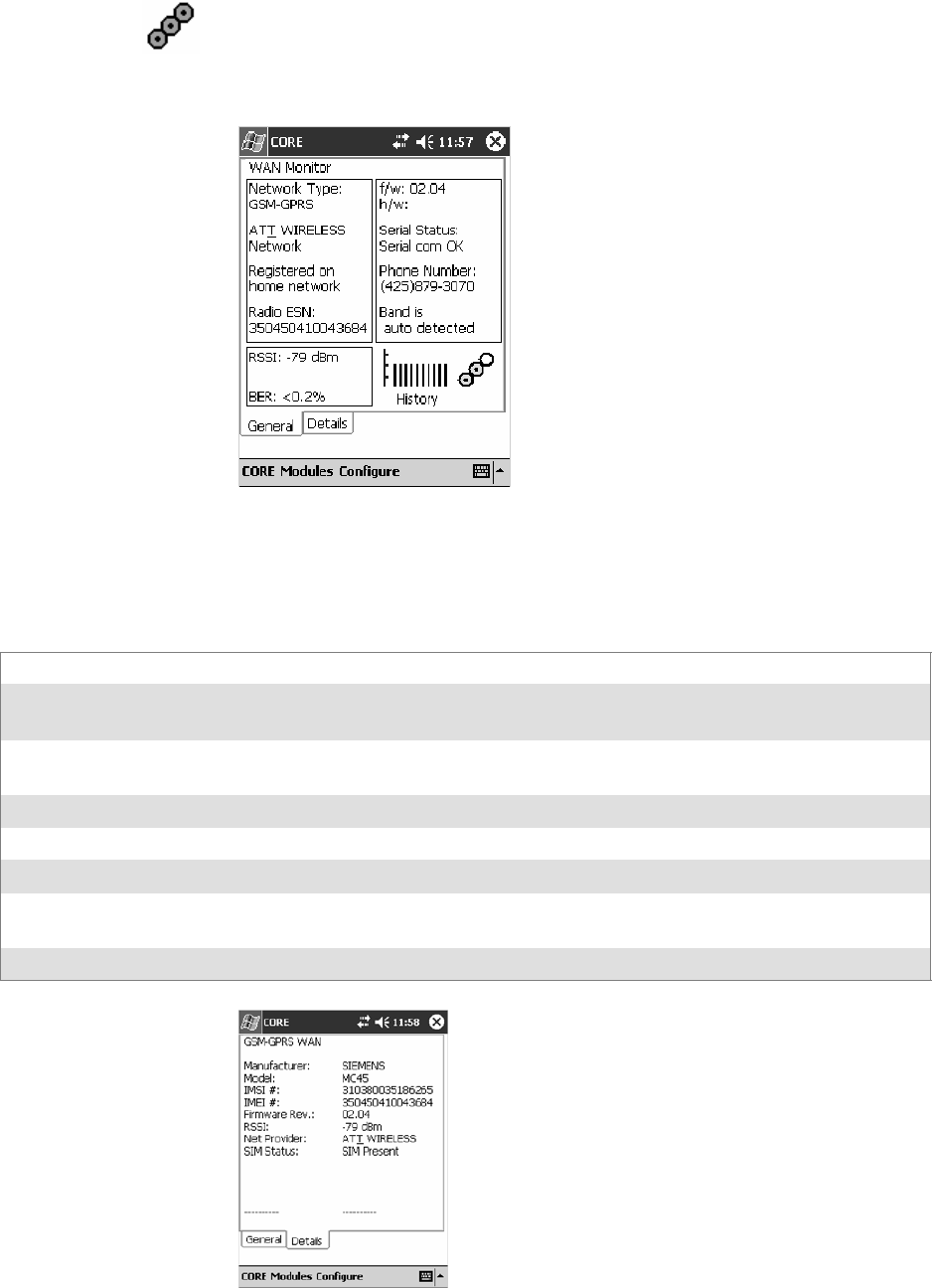
Network Support—Chapter 4
139700 Series Color Mobile Computer User’s Manual
Friendly Indicator:
Usually indicates the signal strength for this radio module. Three filled
dots indicate a high quality or strong signal. Three empty dots indicate
that the signal is out of range or there is no signal detected.
WAN Monitor — Details
Below are descriptions and meanings for each piece of information pro-
vided via the Details tab. Most of this is similar to what is shown under
the General tab. Note that the information is listed alphabetically.
Firmware Rev Identifies the firmware version, if available.
IMEI # The IMEI (International Mobile station Equipment Identity) serial number of the GSM/GPRS
radio module.
IMSI # Shows the IMSI (International Mobile Subscriber Identity) number assigned to the SIM card
installed in this 760 Computer.
Manufacturer Lists the name of the manufacturer that developed this radio module, such as “Siemens.”
Model Lists the product name for this radio module, such as “MC45.”
Net Provider Lists the name of the service providing the network support.
RSSI Displays the RSSI frequency or lists “Unavailable” if there is no signal or the signal cannot be
retrieved from the radio module.
SIM Status Identifies whether a SIM card is installed in this 760 Computer.
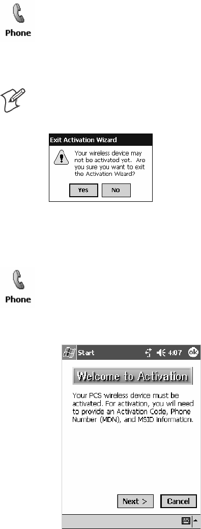
Network SupportChapter —4
140 700 Series Color Mobile Computer User’s Manual
Microsoft Phone Application (761 Computers with CDMA Radios)
With the WAN radio module installed in your 761 Computer, you can
send and receive telephone calls. Use the speaker on the back of the com-
puter as your earpiece and use the connector on the bottom of the com-
puter for your mouthpiece.
Tap Start >Programs >thePhone desktop icon or tap Start >Phone
from the Today screen to access the application which processes your
phone calls. Tap the Close button in the upper right corner of this
application to close.
Data Provisioning (Sprint)
Note: If you wish to do this activation another time, tap Cancel to close
this wizard, then tap Yes.
It is necessary to initiate activation before using your Microsoft Phone ap-
plication. Below are the instructions:
1From the Phone application, tap Tools >Activation Wizard.
2Have your activation code, phone number (MDN), and MSID infor-
mation ready before you tap Next to continue. You can get this infor-
mation from your network provider.
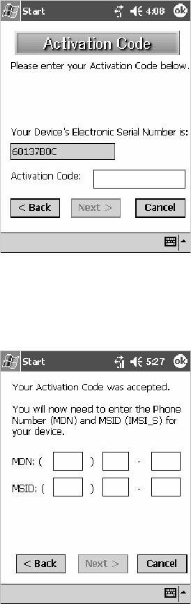
Network Support—Chapter 4
141700 Series Color Mobile Computer User’s Manual
3Enter your 6-digit activation code, then tap Next to continue.
4Enter your phone number and MSID from Sprint, then tap Next to
continue.
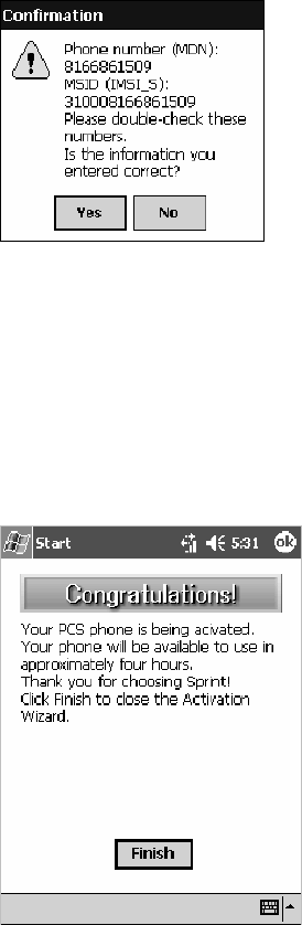
Network SupportChapter —4
142 700 Series Color Mobile Computer User’s Manual
5The application prompts whether the information entered is correct. If
so, tap Yes to continue, otherwise tap No to return to the MSN and
MSID screen.
6Note that voice service is available immediately. Data service take a
minimum of four hours of activation before you can use the service. If
after four hours, a data connection is not established, see “Data Provi-
sioning” on page 140 to manually launch data provisioning.
The application acknowledges that your phone will be in service in four
hours. Tap Finish to close the wizard.
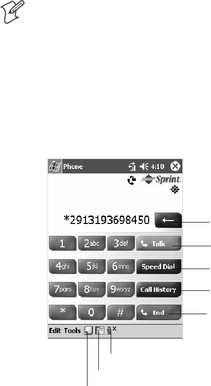
Network Support—Chapter 4
143700 Series Color Mobile Computer User’s Manual
Phone Application
Note: Wait at least four hours after activation is complete before using this
application. Data provisioning should occur automatically. Network infor-
mation about your 761 Computer needs to propogate through the Sprint
Network after the activation is complete.
If data provisioning does not occur automatically, tap Start >Settings >
the Personal tab>thePhone icon. Tap the Data tab, then tap Provision
to initiate a session.
Tap the appropriate keys to enter a telephone number, then tap Talk to
dial the number. Tap End to “hang up” the phone.
Tap this to dial the phone number
shown above the keypad.
Tap this to backspace one digit.
Tap this to select a previously
dialed number.
Tap this to view your previous calls.
Tap this to “hang up” your current
call.
Tap this to access the Contacts application.
Tap this toggle the mute option.
Tap this to access the Notes application.
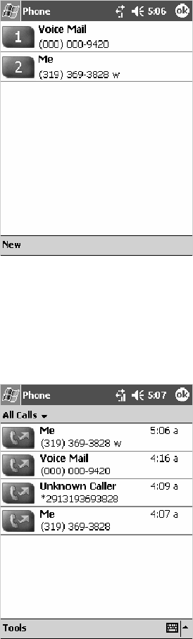
Network SupportChapter —4
144 700 Series Color Mobile Computer User’s Manual
Speed Dial
Tap Speed Dial to select a telephone number with which the 761 Com-
puter is to dial automatically. To add to this list, use the Contacts applica-
tion. See Chapter 2, “Windows Mobile 2003,” for more information about
the Contacts application.
Call History
Tap Call History to note the telephone numbers that were previously
dialed from this 761 Computer.
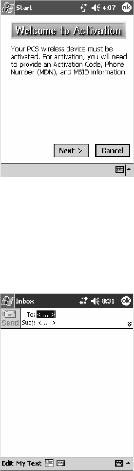
Network Support—Chapter 4
145700 Series Color Mobile Computer User’s Manual
Tools
Use the Tools menu to send a voice mail, access the Activation Wizard,
send an SMS email message, or configure phone settings.
STap Tools >Voice Mail to call and leave a voice message.
STap Tools >Activation Wizard to access the wizard with which to acti-
vate your 761 Computer. Be sure to have an activation code, a phone
number, and MSID information ready. See page 140 for instructions on
using this wizard.
STap Tools >Send SMS tab to access the Inbox application and send an
SMS (Short Messaging Service) message. Be sure to have an SMS num-
ber ready to send the message — this is usually the mobile phone num-
ber. See Chapter 2, “Windows Mobile 2003,” for information about the
Inbox application.
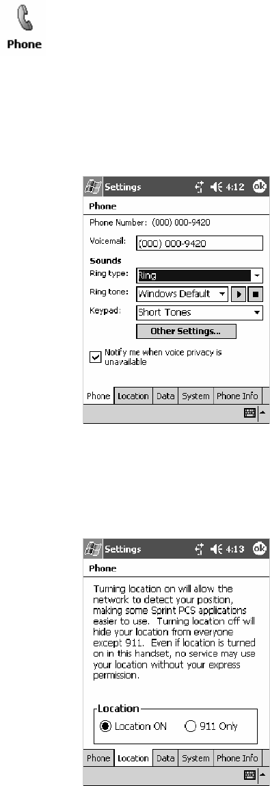
Network SupportChapter —4
146 700 Series Color Mobile Computer User’s Manual
Phone Settings
Either select Tools >Options from the Phone application or select Start >
Settings >thePersonal tab>thePhone icon to access the Phone Settings
control panel applet.
STap the Phone tab to customize your phone settings such as the ring
type and ring tone to use for incoming calls, and the keypad tone to use
when entering phone numbers. Tap Other Settings to go to the Sounds
& Notifications control panel applet. Select Start >Help for more online
information about this feature.
STap the Location tab to toggle between letting your location be visible
for everyone to detect and hiding your location from everyone except
911.
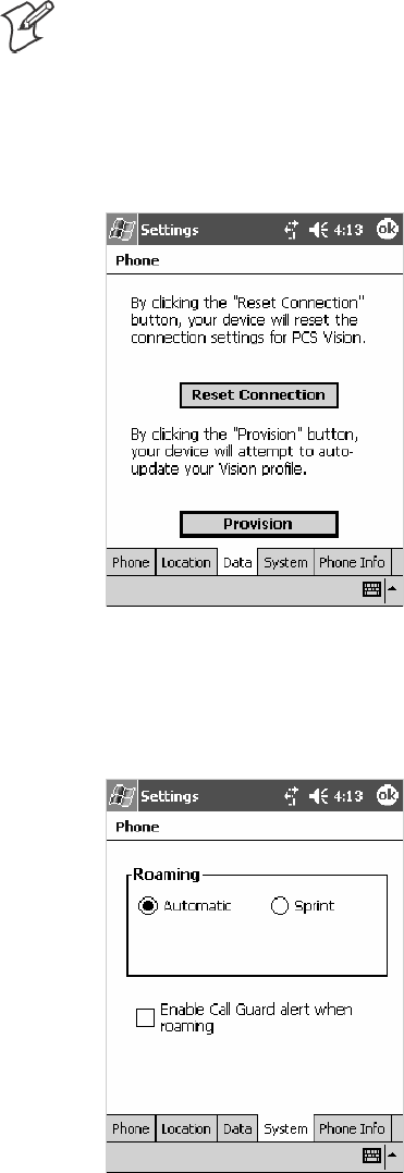
Network Support—Chapter 4
147700 Series Color Mobile Computer User’s Manual
STap the Data tab to either reset your connection settings for PCS Vi-
sion or update your PCS Vision profile.
If your 761 Computer is unable to make a data connection and it has
been more than four hours since activation, you can launch data provi-
sioning from this screen. Tap Provision, then follow the prompts. This
would take several minutes to set up the data connections.
Note: The data provisioning process can be automatically initiated by
the Sprint network, by attempting to make a cellular line connection to
the WAN before the 761 Computer is data provisioned, or by manually
starting the connections through this screen. Intermec recommends that
Sprint Network “push” the data provisioning to your unit. This should oc-
cur shortly after the voice activation is complete.
STap the System tab to toggle between automatic or Sprint roaming and
to enable the Call Guard alert when roaming.
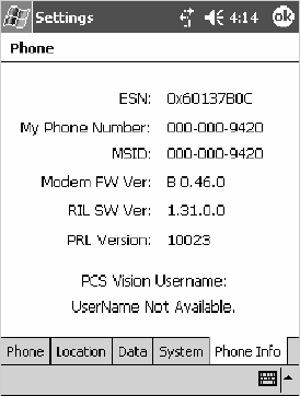
Network SupportChapter —4
148 700 Series Color Mobile Computer User’s Manual
STap the Phone Info tab to view the phone settings.
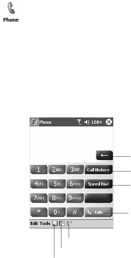
Network Support—Chapter 4
149700 Series Color Mobile Computer User’s Manual
Microsoft Phone Application (761 Computers with GSM Radios)
With the WAN radio module installed in your 761 Computer, you can
send and receive telephone calls. Use the speaker on the back of the com-
puter as your earpiece and use the connector on the bottom of the com-
puter for your mouthpiece.
Tap Start >Programs >thePhone desktop icon or tap Start >Phone
from the Today screen to access the application which processes your
phone calls. Tap the Close button in the upper right corner of this
application to close.
Activation
The GSM phone is activated via a SIM card that you can purchase from
your network provider.
Phone Application
Tap the appropriate keys to enter a telephone number, then tap Talk to
dial the number.
Tap this to dial the phone number
shown above the keypad.
Tap this to backspace one digit.
Tap this to select a previously
dialed number.
Tap this to view your previous calls.
Tap this to access the Contacts application.
Tap this toggle the mute option.
Tap this to access the Notes application.
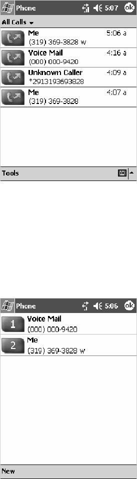
Network SupportChapter —4
150 700 Series Color Mobile Computer User’s Manual
Call History
Tap Call History to note the telephone numbers that were previously
dialed from this 761 Computer.
Speed Dial
Tap Speed Dial to select a telephone number with which the 761 Com-
puter is to dial automatically. To add to this list, use the Contacts applica-
tion. See Chapter 2, “Windows Mobile 2003,” for more information about
the Contacts application.
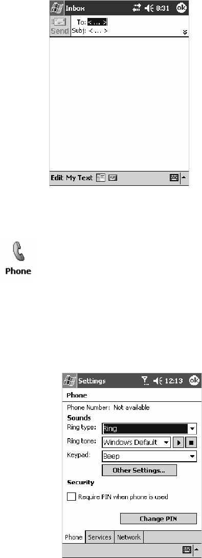
Network Support—Chapter 4
151700 Series Color Mobile Computer User’s Manual
Tools
Tap Tools >Send SMS tab to access the Inbox application and send an
SMS (Short Messaging Service) message. Be sure to have an SMS number
ready to send the message — this is usually the mobile phone number. See
Chapter 2, “Windows Mobile 2003,” for information about the Inbox ap-
plication.
Phone Settings
Either select Tools >Options from the Phone application or select Start >
Settings >thePersonal tab>thePhone icon to access the Phone Settings
control panel applet. Select Start >Help for more online information about
these features.
STap the Phone tab to customize your phone settings such as the ring
type and ring tone to use for incoming calls, and the keypad tone to use
when entering phone numbers. Tap Other Settings to go to the Sounds
& Notifications control panel applet.
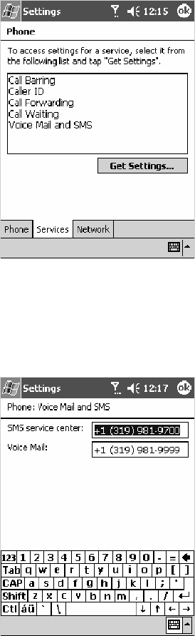
Network SupportChapter —4
152 700 Series Color Mobile Computer User’s Manual
STap the Services tab to access settings for any of the provided services.
Tap any of the settings, then tap Get Settings.Makeyourchanges,then
tap ok to return to the Settings screen. Below is a sample Settings
screen.
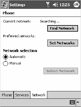
Network Support—Chapter 4
153700 Series Color Mobile Computer User’s Manual
STap the Network tab to find, set, or select the type of network on
which this phone is to communicate.
Network SupportChapter —4
154 700 Series Color Mobile Computer User’s Manual
PhoneUtility (760 Computers with GPRS Radios)
Note: This application is for 760 Computers with GPRS radios only, due
to E911 requirements issued by the FCC. In the United States, voice is
not an option on 760 Computers with CDMA radios.
With the WAN radio module installed in your 760 Computer, you can
send and receive telephone calls. Use the speaker on the back of the com-
puter as your earpiece and use the connector on the bottom of the com-
puter for your mouthpiece.
Tap Start >PhoneUtility from the Today screen to access the application
which will process your phone calls. Tap Exit or ok to close this
application and return to the Today screen.
Audio Mode
Select either Handset or Speakerphone from the Audio Mode box, then
do the following to send or answer a phone call:
STap the numbers for a phone call, using Clear to erase each digit, then
tap Send to initiate the call.
STap Answer to receive an incoming call.
STap End to disconnect a transaction.
SDrag the Vol slider up or down to adjust the speaker volume.
SDrag the Mic slider up or down to adjust the microphone sensitivity.
Handset Audio Mode Speakerphone Audio Mode
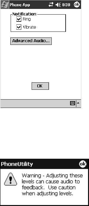
Network Support—Chapter 4
155700 Series Color Mobile Computer User’s Manual
Notification
Tap Settings to set your 760 Computer to either ring or vibrate or do
both, then tap OK or ok to return to the Audio Mode screen. If you need
to adjust the audio settings, tap Advanced Audio to continue.
Advanced Audio
Tap ok to close the warning and continue.
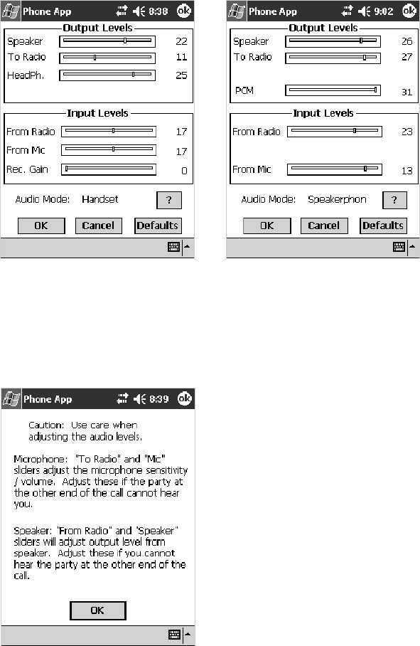
Network SupportChapter —4
156 700 Series Color Mobile Computer User’s Manual
Drag the appropriate slider bars left or right to adjust the output and in-
put levels. Tap Defaults to return the handset or speakerphone levels to
their factory defaults. Click OK or ok to return to the Notification screen.
Handset Output/Input Levels Speakerphone Output/Input Levels
Tap ?for more information on these level settings, then click ok or OK to
return to the Output/Input Levels screen.

Network Support—Chapter 4
157700 Series Color Mobile Computer User’s Manual
SB555 Watcher (760 Computers with CDMA Radios)
The SB555 Watcher program is used on the 760 Computer with CDMA
radios only. Use this primarily to activate the WAN radio. Once the WAN
radio is activiated, you can remove the SB555 Watcher program from the
760 Computer.
This tells you how to set up your CDMA radio in your 760 Computer.
Below are terms to familiarize you with CDMA radio technology:
Note: Set up and provision information is also available in the 700 Color
CDMA Radio Setup Quick Start Guide P/N: 962-054-063.
Activation The process of programming the radio with the lock code (MSL) and phone number (MIN) to
allow it to communicate on the provider’s network. Once activation is complete you can make
voice calls (if enabled by the carrier) with the mobile computer.
Data Provisioning The process of activating the ability for the CDMA radio to establish data connections, such as
connecting to the Internet. The CDMA radio makes data connection only after it is activated
and data provisioned.
NID (Network ID) A numeric value programmed into the CDMA radio at the factory or during the activation
process. Your carrier may or may not use this value, but your carrier may provide this for ac-
tivation purposes.
SID (System ID) A numeric value programmed into the CDMA radio at the factory or during the activation
process. This number is used by your carrier to determine if the radio belongs to its CDMA
network. Your carrier may provide this number for activation purposes.
Note: Descriptions in this chapter are for Sprint PCS, Bell Mobility, Te-
lus, and Verizon Networks versions of the SB555 Watcher program. Oth-
er carriers may be added pending regulatory and carrier approval.
Copying CDMA Radio Module CAB Files from Intermec Web Site
Copy CAB files from the Intermec web site at www.intermec.com onto
your desktop. Note that this is subject to change.
1Select Service & Support >Developers Support fromthebluenaviga-
tion bar on the Intermec home page.
2Select 700 Color Support from the Developers Support navigation co-
lumn on the left side of the screen.
3Select Downloads from beneath the 700 Color Support selectioninthe
Developers Support navigation column on the left side of the screen.
4Select WWAN from the center of the screen, beneath the “Downloads”
title.
5From beneath the “Sierra Wireless ‘Watcher’ Application” title, down-
load any of the CAB files shown, then choose your carrier CAB files.
Intermec recommends one of two methods with which to load these CAB
files onto your 760 Computer: via the Microsoft ActiveSync application
(next paragraph) or via a CompactFlash or Secure Digital storage card
(next page). See Chapter 3, “Installing Applications,” for more information
about these methods.
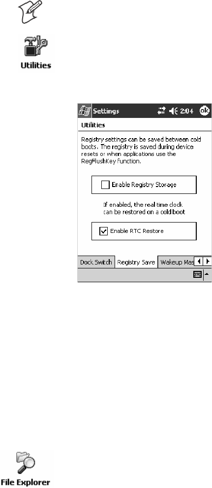
Network SupportChapter —4
158 700 Series Color Mobile Computer User’s Manual
Via Microsoft ActiveSync
You can transfer files from your desktop to your 760 Computer via Micro-
soft ActiveSync. See Chapter 2, “Windows Mobile 2003” for more infor-
mation about ActiveSync.
1Obtain software from the Intermec web site as described earlier. Down-
load the software to any location on your 760 Computer, such as the
Temp folder via the My Device root location.
2Tap the carrier CAB file to install the application.
3Go to “Finishing the Installation” on page 159.
Via a CompactFlash or Secure Digital Storage Card
Note: These instructions are based on default locations. You can change
the location to which to copy your CAB files.
1Make sure the Registry Restore feature on your 760 Computer is dis-
abled. Select Start >Settings >theSystem tab. Tap the Utilities desk-
top icon, then the Registry Save tab. Clear the Enable Registry Save
box.
2Copy the CAB files for your carrier to your CompactFlash or Secure
Digital storage card after downloading it from the web site.
3Cold-boot your 760 Computer. Remove the battery pack and press the
reset button in the bottom of the battery compartment.
4Go through the normal getting started steps detailed in your 700 Color
CDMA Radio Setup Quick Start Guide.
5Install the CompactFlash or Secure Digital memory card into the card
slot in your 760 Computer. Note that if you do not want the CAB files
erased after installation, set the CAB file attributes to “read-only” after copy-
ing them to the storage card.
6From the 760 Computer, tap Start >Programs >theFile Explorer
icon.
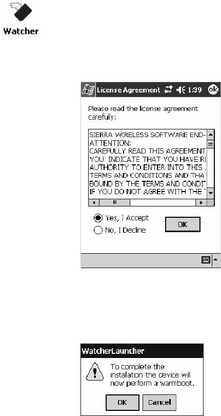
Network Support—Chapter 4
159700 Series Color Mobile Computer User’s Manual
7Tap the pull-down menu for My Documents and tap the My Device
root location.
8If you are using a CompactFlash storage card,
tap Storage Card.
If you are using an Secure Digital storage card,
tap SDMMC Disk.
9Scroll down, then tap the Sprint Watcher CAB file to install the ap-
plication.
10 Go to “Finishing the Installation” in the next paragraph.
Finishing the Installation
Do the following to run the SB555 Watcher application. Be sure to do
step 1 as it is important to perform a warm-boot on your 760 Computer.
Upon restart, the Watcher application sets up on the 760 Computer for
activation.
1Tap Start >Programs >theWatcher icon.
2Tap Yes, I accept to accept the license agreement, then tap OK to con-
tinue. Note that this license agreement does not appear again after this
installation.
3Tap OK for the 760 Computer to perform a warm-boot and complete
the installation.

Network SupportChapter —4
160 700 Series Color Mobile Computer User’s Manual
Activation
Note: Set the date and time before doing this activation.
SB555 Watcher is for activation and data provisioning. Once you enable
voice capability, data capability, or both depending on the carrier, remove
this program from the system by cold-booting your computer.
Intermec Technologies does not recommend using the SB555 Watcher
program to make data and voice calls on a daily basis for these reasons:
SThe SB555 Watcher application is a third-party application unaware of
certain power management methods used in your 760 Computer.
Therefore, the application consumes more power than necessary.
SThe application size consumes memory better used for your application
data.
The process of setting up the account with your carrier and enabling the
CDMA WAN radio in your 760 Computer is called activation. To proper-
ly function, program the CDMA device with the necessary information
and set up the network carrier account. If either piece has errors, the de-
vice does not function on the CDMA network.
The CDMA radio is pre-programmed for a specific carrier, such as Sprint,
Telus, Bell Mobility, Verizon, etc.). Therefore, information about your
radio should already be in your carrier’s database.
You need to notify the carrier and set up mobile accounts for each unit
you are activating. The Electronic Serial Number (ESN hex 63xxxxxx)
that you need to supply to your carrier is located in two places:
SOn the outside of the 760 Computer shipping box.
SOn the inside of the 760 Computer battery compartment.
The ESN comes in both decimal and hexadecimal formats. Most carriers
accept either format, but with a preference for the decimal format. You
only need to provide one number to your carrier.
SThe decimal format consists of 11 digits, beginning with “099.”
SThe hexadecimal format is an 8-digit number, beginning with “63.”
Accounts for Verizon and Sprint carriers can be set up for data only. Cana-
dian carriers (Telus and Bell Mobility) can be set for data only, voice only,
or both voice and data. This is determined by your application and the
services your carrier offers.
After the all ESNs are provided to the carrier and the carrier has estab-
lished the accounts, you will be provided with the lock codes and tele-
phone numbers needed to complete the activation process. You use the
SB555 Watcher program to accomplish this task. Be sure to write down this
information for future use.
Note: Ensure that you receive a spreadsheet with your order that calls out
all ESNs in both decimal and hexadecimal formats.
Note: Keep the activation information for your devices in a safe, accessible
place should you have any future issues.
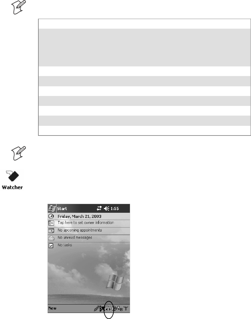
Network Support—Chapter 4
161700 Series Color Mobile Computer User’s Manual
Note: Not all of the elements listed are required by all service providers.
ESN of the modem
Lock/ActivationCode(maybetermedoneofthefollowing):
SMSL — Master Subsidy Lock
SOTSL — OneTime Subsidy Lock
SSPC — Service Provisioning Code
SOTKSL — One Time Key Subsidy Lock
SID (System ID)
NID (Network ID)
User Name
Password
MIN
MSD
MDN
Note: The activation process for your Watcher version may vary from the
following steps. Thus, you may not have to do all of them.
1Tap Start >Programs >theWatcher icon or tap the Watcher icon from
the NDISTRAY via the Today screen (circled in the following illustra-
tion) to launch the SB555 Watcher program.
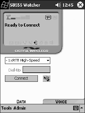
Network SupportChapter —4
162 700 Series Color Mobile Computer User’s Manual
2The Activation Wizard should start automatically. If not, then tap
Admin >Activation Wizard from the bottom of the screen.
3Follow the screen prompts, tapping Next to move from one screen to
the next.
4When you reach the Activation screen, select Manual Activation.
5At the appropriate screen, enter the Activation Code (OTSL, MSL,
OTKSL, or SPC) provided by your carrier and tap Next.
6Enterthephonenumberprovidedwhenyour760Computerwasacti-
vated and tap Next.
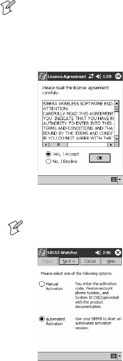
Network Support—Chapter 4
163700 Series Color Mobile Computer User’s Manual
Verizon Automated Activation Process
Note: This process takes approximately 60 seconds.
Do the following to activate Verizon on your 760 Computer:
1After initializing the Watcher program, tap Yes, I accept to accept the
license agreement, then tap OK to perform a warm-start on the 760
Computer. Note this license agreement does not appear again after the
installation.
2Start the Watcher program again, select Automated Activation,then
click Next.
Note: YoumustbeintheVerizoncoverageareatoactivateyour760
Computer and only in the location of intended use.
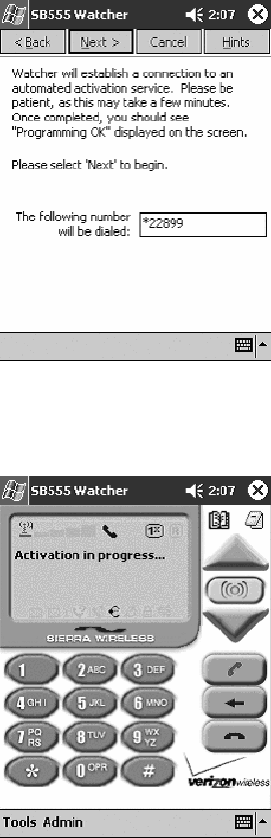
Network SupportChapter —4
164 700 Series Color Mobile Computer User’s Manual
3Click Next,clickNext again to dial the number displayed on the screen.
4The activation process starts automatically.
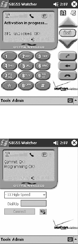
Network Support—Chapter 4
165700 Series Color Mobile Computer User’s Manual
5You will see a series of unlock codes on your screen.
6The following illustration shows the result of a successful activation.
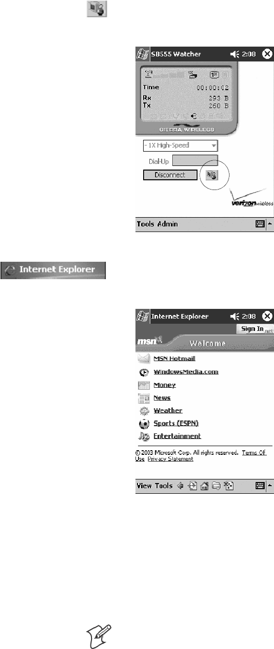
Network SupportChapter —4
166 700 Series Color Mobile Computer User’s Manual
7Click the Connect button (circled in the following illustration) to connect
to the carrier’s network.
8Select Start >Internet Explorer, then choose a web site. Your unit is
now successfully activated.
9Perform a cold-boot on your 760 Computer to uninstall the Watcher
application. Watcher is intended for activation purposes only. Intermec
recommends using the following for establishing and maintaining con-
nection to the WAN radio.
SCustom application using Intermec WWAN Toolkit API
SCustom customer application using Connection Manager Interface
Note: When connecting to the WAN radio via Pocket PC Connection
Manager, use the 10-digit phone number@vzw3g.com for the user
name (such as 1234567890@vzw3g.com) and “vzw” for the password.
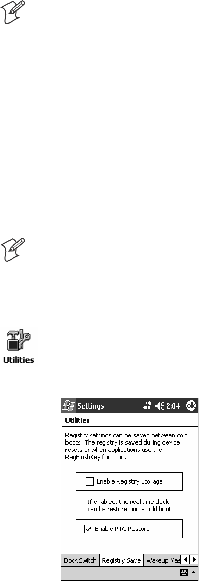
Network Support—Chapter 4
167700 Series Color Mobile Computer User’s Manual
Sprint Automated Activation Process
Note: Sprint PCS uses a data provisioning method termed IOTA (Internet
Over The Air) to complete its activation and data enablement. The follow-
ing steps detail how to properly activate and data provision your 760
Computer.
Do the following to set up activation:
1Provide Sprint with your ESN, rate plan, and account information.
2Sprint provides you with the following for each ESN:
SMDN, such as 214-555-5555
SMSID, such as 214-555-5555
SMSL/OTKSL (Activation Code), such as 945614
SNAI (Network Access Identifier), such as the following:
CustomerNameo103@sprintpcs.com
You must use a Secure Digital storage card with only the
SPRINT_WATCHER.CAB file in the “\SDMMC/Cabfiles” directory.
Note: Other CAB files in the “SDMMC/Cabfiles” directory may cause
problems with testing — remove or uninstall these before proceeding.
You need at least 80% (4 of 5 bars) CDMA signal strength for a successful
over-the-air activation.
Download and Activate Sprint Watcher
1Make sure the Registry Restore feature on your 760 Computer is dis-
abled. Select Start >Settings >theSystem tab. Tap the Utilities desk-
top icon, then the Registry Save tab. Clear the Enable Registry Save
box.
2Perform a cold-boot on your 760 Computer, then go through the nor-
mal Pocket PC set-up (i.e. Align Screen etc.).
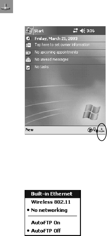
Network SupportChapter —4
168 700 Series Color Mobile Computer User’s Manual
3Important! Set the Date and Time.
4Tap the Sprint_Watcher_PPC_2002-03xxx.CAB file to perform the
installation.
5Perform a warm-boot on your 760 Computer to load the CAB file.
6From the Today screen, tap the LAN Network icon in the System Tray
(circled in the following illustration).
7In the NDISTRAY pop-up menu (the Network Driver Interface Speci-
fication tray application), select No Networking and Auto FTP Off.
Tap anywhere on the screen to close the menu.
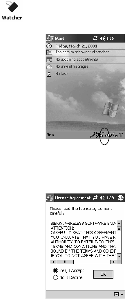
Network Support—Chapter 4
169700 Series Color Mobile Computer User’s Manual
8Tap Start >Programs >theWatcher icon or tap the Watcher icon from
the NDISTRAY via the Today screen (circled in the following illustra-
tion) to launch the SB555 Watcher program.
9Tap Yes, I accept to accept the license agreement, then tap OK to con-
tinue. Note that this license agreement does not appear again after this
installation.
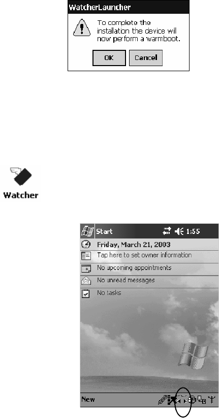
Network SupportChapter —4
170 700 Series Color Mobile Computer User’s Manual
Tap OK for the 760 Computer to perform a warm-boot and complete the
installation.
Using Sprint Watcher
Before you start using the Sprint Watcher application, make sure you
match the correct ESN with each 760 Computer and that you have at least
80% CDMA signal strength.
1Tap Start >Programs >theWatcher icon or tap the Watcher icon from
the NDISTRAY via the Today screen (circled in the following illustra-
tion) to launch the SB555 Watcher program.
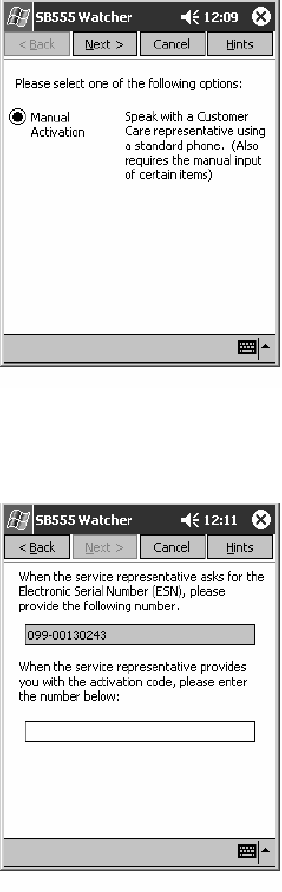
Network Support—Chapter 4
171700 Series Color Mobile Computer User’s Manual
2If your 760 Computer was not previously activated, Watcher automati-
cally starts the Activation Wizard. Otherwise, select Manual Activation
to continue.
3EntertheMSLorlockcodereceivedfromSprint.
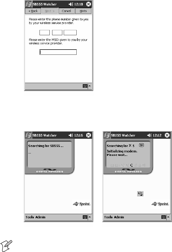
Network SupportChapter —4
172 700 Series Color Mobile Computer User’s Manual
4Enterthephonenumber(MIN)andMSIDreceivedfromSprint.
Thesenumbersmaybethesame.
5After entering the phone number and MSID, the modem resets. Watch-
er displays the following two screens:
Note: If the “searching for SB555” screen does not proceed to the next
screen after 30-40 seconds, perform a warm-boot on your 760 Comput-
er, then restart the Watcher program.
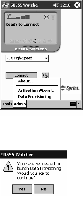
Network Support—Chapter 4
173700 Series Color Mobile Computer User’s Manual
Data Provisioning
At this point, the activation on the Sprint network is complete. It is rec-
ommended by Sprint to wait before you launch data provisioning to allow
time for the activation to propagate through your Sprint network.
Before you manually launch data provisioning, wait at least 30 minutes. In
some cases, you may have to wait up to two hours.
1If Data Provisioning does not start automatically, select Admin >Data
Provisioning from the bottom menu bar.
2Tap Yes to proceed with data provisioning.
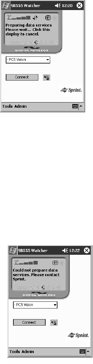
Network SupportChapter —4
174 700 Series Color Mobile Computer User’s Manual
Activation over the air typically takes 1–20 minutes.
If data provisioning fails, do the following:
SIf Data Provisioning fails and the message “could not prepare data ser-
vices, please contact Sprint” displays, retry the Data Provisioning step by
tapping the “Admin” menu icon at the bottom of the Watcher screen.
Select “Data Provisioning...” and answer “yes” to the request.
SIf after several attempts to complete the Data Provisioning over the air,
it may be necessary to manually enter the data activation method.
SGo to Intermec Knowledge Central www.intermec.com, then select Ser-
vice & Support >Knowledge Central) to learn about manual activa-
tion. The article (number 5749) is titled How to Manually Activate a
Sprint CDMA WAN Radio in the 760 Device.
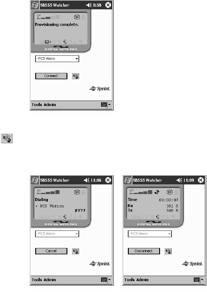
Network Support—Chapter 4
175700 Series Color Mobile Computer User’s Manual
3The following screen appears once data provisioning is complete:
4Test the data connection by tapping on the “connect” button to make a
data connection to the network. Watcher progresses through the follow-
ing two screens. Once you see the second screen you know that your
mobile computer has successfully connected to the 1XRTT network.
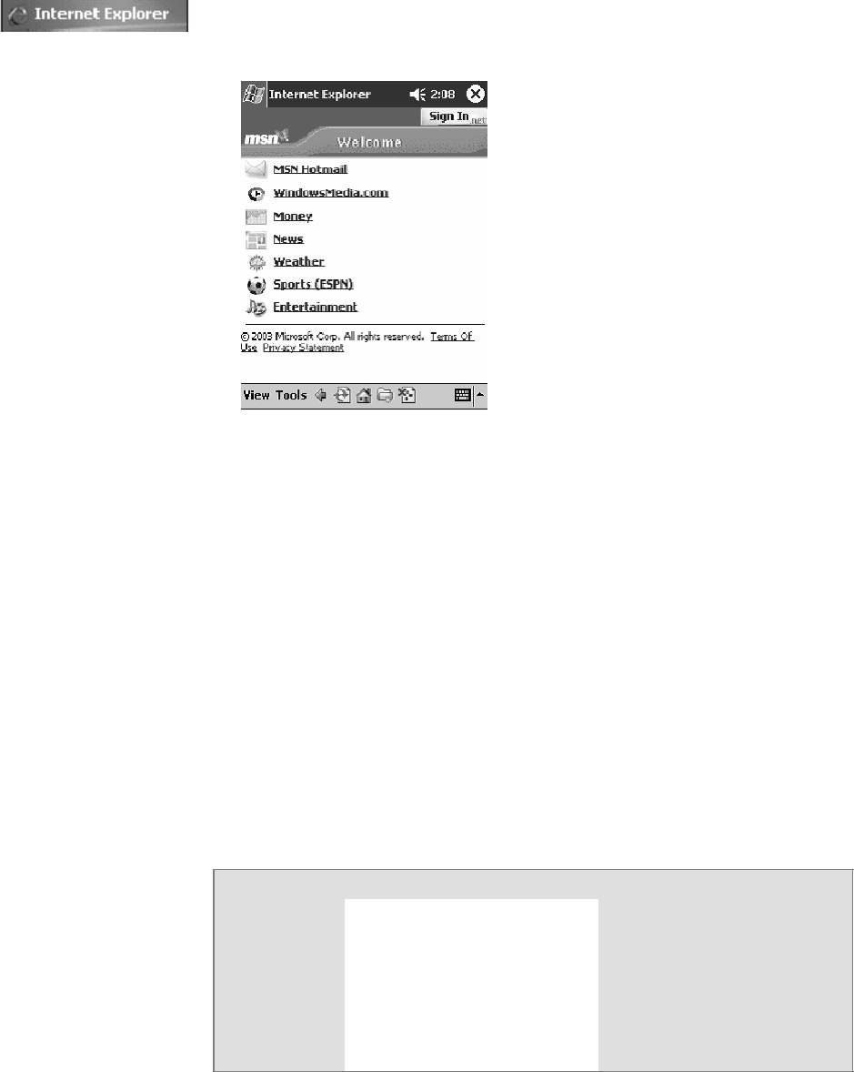
Network SupportChapter —4
176 700 Series Color Mobile Computer User’s Manual
5Select Start >Internet Explorer, then choose a web site. Your unit is
now successfully activated.
Perform a cold-boot on your 760 Computer to uninstall the Watcher ap-
plication. Watcher is intended for activation purposes only. Intermec rec-
ommends using the following for establishing and maintaining connection
to the WAN radio.
SCustom application using Intermec WWAN Toolkit API
SCustom customer application using Connection Manager Interface
Telus and Bell Mobility Activation
Activation of Bell Mobility and Telus are similar to the first portion of the
Sprint activation process. Follow the instructions for manual activation
using the Bell Mobility Watcher.CAB or Telus Watcher.CAB file to install
the applicable application. Enter the activation lock codes and phone num-
bers as requested.
Username, Password, SID Information
Bell Mobility Telus
Username 10 digit phone
number@1xbell.ca
10-digit phone
number@1x.telusmobility.com
Password Original Voice Mail system pass-
word (usually a 4 digit number)
This is available from the activat-
ing organization.
The 11-digit ESN printed inside
the 760 Computer battery
compartment, begins with 099.
SID 16420 16422

Network Support—Chapter 4
177700 Series Color Mobile Computer User’s Manual
AT Command Interface (760 Computers)
This interface specification is based on the following recommendation:
SETSI GSM 07.05:
European Digital Cellular Telecommunication System (phase 2)
Use of DTE-DCE interface for Short message and cell broadcast service.
SETSI GSM 07.07:
European Digital Cellular Telecommunication System (phase 2)
AT command set for GSM Mobile Equipment.
SITU-T Recommendation V.25 ter
Serial asynchronous automatic dialing and control.
Note: You need the Adobe Acrobat Reader application to view a PDF do-
cument. Go to www.adobe.com/prodindex/acrobat/readstep.html to install
or download the latest Adobe Acrobat Reader.
Command Set for Sierra Wireless SB555
Use the AT command interface from Sierra Wireless to program the
CDMA/1xRTT SB555 radio module. Documentation for this interface is
available via the following URL. Click the “General AT command refer-
ence” link for a PDF document, which is 680 KB in size. Note that this
URL is subject to change.
www.sierrawireless.com/ProductsOrdering/embedded_docs.html
Command Set for Siemens MC45 or MC46
Use the MC45 or MC46 AT command interface from Siemens AG to
program the GPRS/GSM MC45 or MC46 radio module. The “MC45
Siemens Cellular Engine AT Command Set”andthe“MC46 Siemens Cellu-
lar Engine AT Command Set” are available either from Intermec Technolo-
gies or from Siemens AG. Contact either your Intermec representative or
the Siemens AG support personnel at the following URL for more infor-
mation. Note this URL is subject to change.
www.siemens-mobile.com/btob/CDA/presentation/ap_btob_cda_presenta-
tion_frontdoor/0,2950,12,FF.html
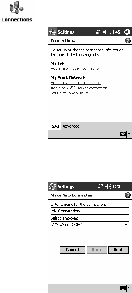
Network SupportChapter —4
178 700 Series Color Mobile Computer User’s Manual
Testing the AT Commands
These commands can be sent to either WAN radio by setting up a dial-up
networking connection to COM4. Do the following to initiate this con-
nection and test these commands to your radio:
1From the 760 Computer, select Start >Settings >theConnections tab
>Connections.UnderMy ISP,tapAdd a new modem connection.
2Enter a name for the connection, select “WANA on COM4” from the
Select a modem drop-down list, then tap Next to continue.
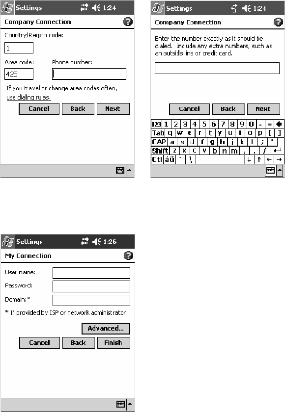
Network Support—Chapter 4
179700 Series Color Mobile Computer User’s Manual
3Enter a phone number as it should be dialed, then tap Next to continue.
Select Start >Help for more information or tap use dialing rules to
make modifications. Note that this screen may vary based on dialing rules.
4Tap Advanced to continue.
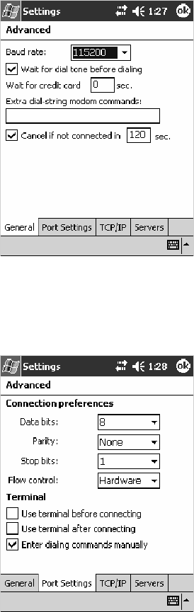
Network SupportChapter —4
180 700 Series Color Mobile Computer User’s Manual
5Select “115200” from the Baud rate drop-down list via the General
page.
6Tap the Port Settings tab, check Enter dialing commands manually,
then tap ok
,then
Finish to return to the Connections screen.
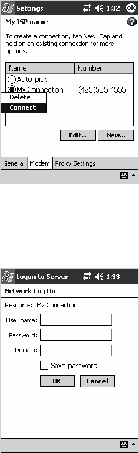
Network Support—Chapter 4
181700 Series Color Mobile Computer User’s Manual
7Tap Manage existing connections from the Connections page, press
and hold the new connection for a pop-up menu, then tap Connect to
initiate the connection.
8Wait about ten seconds for the Network Log On screen, then tap OK.
Note: You do not need to enter any information within the Network Log
On screen.
Useeithertheonscreenkeyboard,orpressthekeystotypeanyoftheAT
commands provided. Press or tap Enter to send each command. The re-
sults of each command sent will print onscreen. Note that each “AT” com-
mand must start with the “at” characters.
STo see what you typed onscreen, type “ate1” to initiate the AT Echo
command, then press Enter.
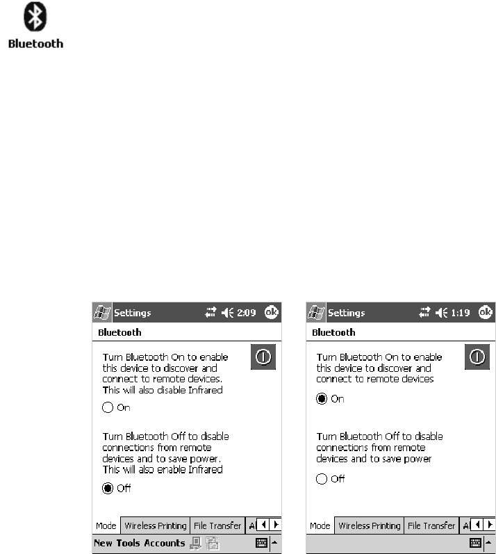
Network SupportChapter —4
182 700 Series Color Mobile Computer User’s Manual
Wireless Personal Area Networking
“Bluetooth” is the name given to a technology standard using short-range
radio links, intended to replace the cables connecting portable and fixed
electronic devices. The standard defines a uniform structure for a wide
range of devices to communicate with each other, with minimal user ef-
fort. Its key features are robustness, low complexity, low power, and low
cost. The technology also offers wireless access to LANs, the mobile phone
network, and the internet for a host of home appliances and portable
hand-held interfaces.
Documentation
Information about other Bluetooth software is in the Wireless Printing
SDK and the Wireless Printing Development Guide (on the Intermec Devel-
oper’s Library CD, via the “\Wireless Printing SDK” directory off the root).
About the Application
Bluetooth is not started automatically by default after a cold-boot is per-
formed. To run Bluetooth, tap Start >Settings >theConnections tab >
the Bluetooth icon. The 700 Color Computer retains the Bluetooth state
when warm-boots are performed, for example:
SIf Bluetooth is active, and a warm-boot was performed, the 700 Color
Computer boots up with the Bluetooth state activated and Bluetooth
virtual COM ports (such as printing) registered. However, you must
reactivate connections, as the system does not do these automatically.
SIf Bluetooth is inactive, and a warm-boot was performed, the 700 Color
Computer boots up with Bluetooth deactivated.
Mode
The default tab activates or deactivates Bluetooth. When Bluetooth is acti-
vated, the 700 Color Computer can discover and connect to remote de-
vices.
700 Color Screen 730 Screen
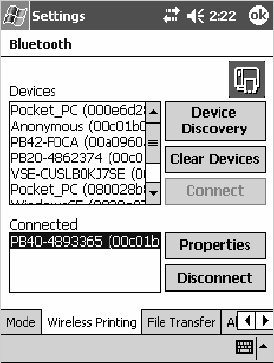
Network Support—Chapter 4
183700 Series Color Mobile Computer User’s Manual
Wireless Printing
Use this tab to print via Bluetooth devices. Tap Device Discovery to disco-
ver (or scan) for remote Bluetooth devices. When the 700 Color Comput-
er is finished scanning, any newly discovered devices appear in the upper
Devices box.
Tap Clear Devices to remove the list from the Devices box.
To print to a Bluetooth device, select any of the devices listed in the
Devices box, then tap Connect. Once connected, the selected device
moves to the lower Connected box.
To view connection information or register a COM port for a device,
from the lower Connected box, select a device, then tap Properties.See
“Properties” on the next page for information.
When done printing to a device, select that device in the Connected box,
then tap Disconnect. This moves the device in question back to the upper
Devices box.
Properties
Select a COM Port from the Choose COM Port box to register for this
device, then check Enable Wireless Printing to complete the COM port
registration. To change your COM port selection, clear (uncheck) the En-
able Wireless Printing box, select a new COM port, then check Enable
Wireless Printing again. Check Default COM ports that already are in use
are grayed out.
When you enable Wireless Printing, a status message is shown near the
bottom of the screen to confirm your action. To print a test page to your
printer, tap PrintTestPage.
Check Default to set this printer to identify the assigned COM Port as the
WPPort in the registry. See the Wireless Printing Development Guide for
more details on WPPort.
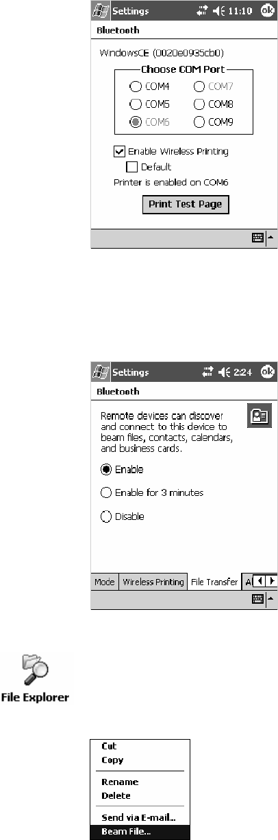
Network SupportChapter —4
184 700 Series Color Mobile Computer User’s Manual
Tap ok to return to the Wireless Printing page.
File Transfer
UsethispagetoenableyourunittoreceivefilesfromanotherBluetooth
device, or from any device that supports this function.
Note that this does not apply to the 730 Computer. From this point, this
transfer is similar to an IrDA file transfer. To transfer a file, tap Start >
Programs >File Explorer and locate the file to transfer. Press and hold on
thefileforapop-upmenu,thenselectBeam File.
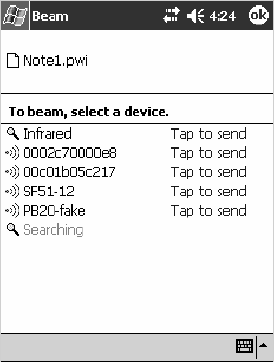
Network Support—Chapter 4
185700 Series Color Mobile Computer User’s Manual
The system searches for a list of Bluetooth devices that will accept a con-
nection from your unit. When the list is complete, tap on a device to
which to send the file. Note: in some cases, the user of the target device has to
“accept” the file before it is transmitted.

Network SupportChapter —4
186 700 Series Color Mobile Computer User’s Manual
AutoIP/DHCP
Automatic Private IP Addressing (AutoIP) is enabled by default in
Windows Mobile 2003. To remain compatible with other versions of
Pocket PC, this setting needs to be enabled. You can configure the registry
settings in the following to set the required AutoIP/DHCP behavior:
SFor Ethernet:
HKEY_LOCAL_MACHINE\Comm\LAN9001\TcpIp
SFot 802.11:
HKEY_LOCAL_MACHINE\Comm\NETWLAN1\TcpIp
Other registry keys that can modify the behavior of AutoIP are as follows.
You can find the appropriate settings and behavior of each of these keys in
Microsoft Help.
SAutoInterval
SAutoMask
SAutoSubnet
SAutoIP
SAutoSeed
When a TCP/IP client cannot find a DHCP server, it generates an AutoIP
address from the 169.254.xxx.xxx block. The client then tries to check for
a DHCP server every 15 seconds and if a DHCP server is found, the client
drops the AutoIP address and uses the address from the DHCP server.
In the MSDN Windows CE documentation available out on the Micro-
soft Developer Network web site (www.msdn.com), see “Automatic Client
Configuration” for more information on AutoIP.
To disable AutoIP, set the AutoCfg registry entry to “0.” If a DHCP serv-
er cannot be found, instead of using AutoIP, the system will display the
“Unable to obtain a server assigned IP address” message.
Note: If you try to disable AutoIP using a CAB file to set the registry value
for AutoIP, remember to set the EnableDHCP value to “1” to keep
DHCP enabled
Note: To extend the number of attempts that a DHCP client makes to get
a DHCP address, use the DhcpRetryDialogue and DhcpMaxRetry registry
settings.
Note: Change the AutoInterval registry key value to make the client retry
moreoftentoobtainaDHCPaddress.

Network Support—Chapter 4
187700 Series Color Mobile Computer User’s Manual
SNMP Configuration on the 700 Color Computer
In short, SNMP is an application-layer protocol that facilitates the ex-
change of management information between network devices. The 700
Color Computer is such an SNMP-enabled device. Use SNMP to control
and configure the 700 Color Computer anywhere on an SNMP-enabled
network.
The 700 Color Computer supports four proprietary Management Infor-
mation Bases (MIBs) and Intermec Technologies provides SNMP support
for MIB-II through seven read-only MIB-II (RFC1213-MIB) Object
Identifiers (OIDs).
Note: You can only query these seven OIDs through an SNMP manage-
ment station.
Management Information Base
The Management Information Base is a database that contains information
about the elements to be managed. The information identifies the manage-
ment element and specifies its type and access mode (Read-Only, Read-
Write). MIBs are written in ASN.1 (Abstract Syntax Notation.1) — a ma-
chine independent data definition language. Note: Elements to be managed
are represented by objects. The MIB is a structured collection of such objects.
You will find the following MIB files either in the 700 Color Management
Tools portion of the Intermec Developer’s Library CD or on the web via
www.intermec.com:
SINTERMEC.MIB
Defines the root of the Intermec MIB tree.
SITCADC.MIB
Defines objects for Automated Data Collection (ADC), such as bar
code symbologies.
SITCSNMP.MIB
Defines objects for Intermec SNMP parameters and security methods,
such as an SNMP security IP address.
SITCTERMINAL.MIB
Defines objects for 700 Color parameters, such as key clicks.

Network SupportChapter —4
188 700 Series Color Mobile Computer User’s Manual
Object Identifiers
Each object has a unique identifier called an OID, which consist of a se-
quence of integer values represented in dot notation. Objects are stored in
a tree structure and OIDs are assigned based on the position of the object
in the tree. For example, the internet OID is equal to 1.3.6.1. Seven MIB
OIDsareshowninthefollowingtable:
MIB Object Identifiers
MIB-II Item OID Group or Table Description
ifNumber 1.3.6.1.2.1.2.1.0 Interfaces Group Indicates the number of adapters
present in the system. For the 700
Color Computer, if one adapter is
present in the system, then ifNum-
ber =1andifIndex=1.
ifIndex 1.3.6.1.2.1.2.2.1.1.ifIndex Interfaces Table (ifTable) A unique value for each interface.
The value ranges between 1 and the
value of ifNumber.
ifDescr 1.3.6.1.2.1.2.2.1.2.ifIndex Interfaces Table (ifTable) A textual string containing informa-
tion about the interface.
ifType 1.3.6.1.2.1.2.2.1.3.ifIndex Interfaces Table (ifTable) An integer containing information
about the type of the interface. It is
equal to 1 for Other.
ipAdEntAddr 1.3.6.1.2.1.4.20.1.1.IpAddress IP address Table
(ipAddrTable)
The IP address to which this entry’s
addressing information pertains
(same as 700 IP address),whereIP
Addressisthevalidnon-zeroIPad-
dress of the 700 Color Computer.
ipAdEntIfIndex 1.3.6.1.2.1.4.20.1.2.IpAddress IP address Table
(ipAddrTable)
Theindexvaluethatuniquelyiden-
tifies the interface to which this
entry is applicable (same as ifIndex).
ipAdEntNetMask 1.3.6.1.2.1.4.20.1.3.IpAddress IP address Table
(ipAddrTable)
The subnet mask associated with
theIPaddressofthisentry(same as
Subnet Mask).
Configuring with SNMP
The community string allows an SNMP manager to manage the 700 Col-
or Computer with a specified privilege level. The default read-only com-
munity string is “public” and “private” is the default read/write communi-
ty string. See the specific configuration parameter to find its OID. To
configure the 700 Color Computers using SNMP:
1Configure700ColorComputersforRForEthernetcommunications.
2Determine the OID (Object Identifier) for the parameter to be chan-
ged. The Intermec base OID is 1.3.6.1.4.1.1963.
3Use your SNMP management station to get and set variables that are
defined in the Intermec MIBs. You can set the traps, identification, or
security configuration parameters for SNMP. See Appendix A, “Confi-
gurable Settings,” to learn more about these parameters.

189700 Series Color Mobile Computer User’s Manual
Printer Support
5
The 700 Series Color Mobile Computer works with the following printers
from Intermec Technologies. Contact an Intermec representative for infor-
mation about these printers.
S6820
A full-page, 80-column printer.
S6808
A 4-inch belt-mount printer.
SPB20
A 2-inch belt-mount printer with a Bluetooth compatible module from
Socket Communications.
S782T
A 2-inch workboard printer.
Note: “700 Color” pertains to 740, 741, 750, 751, 760, and 761 Com-
puters unless otherwise noted.
Printer SupportChapter —5
190 700 Series Color Mobile Computer User’s Manual
Printing ASCII
The following methods for printing using Pocket PC at this time is as fol-
lows:
SAdd port drivers to print ASCII directly to the port.
SUse LinePrinter ActiveX Control from the Software Developer’s Kit
(SDK) — see the SDK User’s Manual for more information.
SVia wireless printing - see the Wireless Printing Development Guide on the
Intermec Developer’s Library CD for more information.
Directly to a Port
Printing directly to the port sends RAW data to the printer. The format of
this data depends upon your application and the printer capabilities.
Youmustunderstandtheprintercommandsavailableforyourspecific
printer. Generally, applications just send raw ASCII text to the printer.
Since you are sending data to the printer from your application directly to
the port you are in complete control of the printers operations. This allows
youtodolineprinting(printonelineatatime)rather than the page for-
mat printing offered by the GDI approach. It is also much faster since data
does not have to be converted from one graphics format to the other (dis-
play to printer). Most Intermec
®
printers use Epson Escape Sequences to
control print format operations.
These commands are available in documentation you receive with your
printers or from technical support. Win32 APIs are required to print di-
rectly to the port.
Directly to a Generic Serial Port
To print directly to a generic serial port printer (non-Intermec printers):
SUse CreateFile() to open ports — COM1 can be opened on most de-
vices.
SUse WriteFile() to send data directly to the printer.
SUse CloseHandle() when you are finished printing to close the port.
IrDA Printer Driver
IrDA printing is only available on the certain devices and is supported di-
rectly by the Windows CE load via the IrSock API provided by the Micro-
soft Win32 API without need for additional drivers. Intermec 6804, 6805,
6806, 6808 and 6820 and other IrDA printers are supported.
Printer Support—Chapter 5
191700 Series Color Mobile Computer User’s Manual
NPCP Printer Driver
The NPCP printer communications driver (NPCPPORT.DLL) is a
Stream Device Driver built into the operating system. The driver supports
only NPCP communications to and from the 6820 and 4820 printers over
a selected serial port.
All applications use WIN32 API functions to access the drivers. Basic op-
erations are easily implemented by applications through the CreateFile(),
WriteFile(), ReadFile(), DeviceIOControl(), and CloseHandle() Win32
APIs.
Operations to upgrade printer modules, perform printer diagnostics, and
get printer configuration are performed largely via DeviceIOControl()
functions.
About NPCP
NPCP (Norand
®
Portable Communications Protocol) is a proprietary
protocol that provides session, network, and datalink services for Intermec
mobile computers in the Intermec LAN environment used with printers
and data communications.
NPCP Driver Installation and Removal
UseLPT9:fortheNPCPprinterdeviceandCOM1forthelastparame-
ter. COM1 is the connection available via the 700 Color Computer.
Applications use the RegisterDevice() function to install the driver.
DeregisterDevice() uninstalls the device driver and frees memory space
when the driver is not required. Use the HANDLE returned by
RegisterDevice() as the parameter to DeregisterDevice().
Use the RegisterDevice() function call as demonstrated below. Specify the
full path name to the driver starting at the root for the RegisterDevice()
function to work properly. The last parameter to RegisterDevice() is a
DWORD that represents the name of the port for the NPCP stream
driver to use. Build this parameter on the stack if it is not to be paged out
duringthecall.Thefirstparameter“LPT”(DeviceName)andthesecond
parameter “9’ (index), indicate the name of the registered device, such as
LPT9. This is used in the CreateFile() function call.
Install()
{HANDLE hDevice;
TCHAR port[6];
port[0] = TCHAR(‘C’);
port[1] = TCHAR(‘O’);
port[2] = TCHAR(‘M’);
port[3] = TCHAR(‘1’);
port[4] = TCHAR(‘:’);
port[5] = TCHAR(0);
hDevice = RegisterDevice ( (TEXT(”LPT”), 9,
TEXT(“\\STORAGE CARD\\WINDOWS\\NPCPPORT.dll”), (DWORD)port);
}
Printer SupportChapter —5
192 700 Series Color Mobile Computer User’s Manual
Opening the NPCP Driver
TheapplicationopenstheNPCPdriverbyusingtheCreateFile()
function. The call can be implemented as follows. The first parameter
“LPT9:”mustreflectthedevicenameandindexusedinthe
RegisterDevice() function call and will fail for any of the following reasons:
hFile = CreateFile(_T(”LPT9:”), GENERIC_WRITE |
GENERIC_READ, 0, NULL, OPEN_ALWAYS, FILE_ATTRIBUTE_NORMAL,
NULL);
SThe port associated with the device during RegisterDevice() is in use.
SThe NPCP device is already open.
SThe share mode is not set to zero. The device cannot be shared.
SAccess permissions are not set to GENERIC_WRITE |
GENERIC_READ. Both modes must be specified.
Closing the NPCP Driver
Using the CloseHandle() (hFile) function closes the NPCP driver. Where
hFile is the handle returned by the CreateFile() function call.
STRUE = the device is successfully closed.
SFALSE = an attempt to close NULL HANDLE or an already closed de-
vice.
Reading from the NPCP Driver
Reading of the NPCP printers is not supported since all responses from
the printer are the result of commands sent to the printer.
DeviceIoControl() functions are provided where data is to be received
from the printer.
Writing to the NPCP Driver
All Print data can be sent to the printer using the WriteFile() function.
The print data written to the driver must contain the proper printer
commands for formatting. If the function returns FALSE, the NPCP error
may be retrieved using IOCTL_NPCP_ERROR. See the description on
the next page.
Printer Support—Chapter 5
193700 Series Color Mobile Computer User’s Manual
NPCP Driver I/O Controls
An application uses the DeviceIoControl() function to specify an printer
operation to be performed. Certain I/O controls are required to bind and
close communication sessions with the printer, and must be completed
before any other commands to the driver can execute properly.
The function returns TRUE to indicate the device successfully completed
its specified I/O control operation, otherwise it returns FALSE. The
following I/O control codes are defined:
#define IOCTL_NPCP_CANCEL
CTL_CODE(FILE_DEVICE_SERIAL_PORT,0x400,METHOD_BUFFERED,FILE_ANY_ACCESS)
#define IOCTL_NPCP_BIND
CTL_CODE(FILE_DEVICE_SERIAL_PORT,0x401,METHOD_BUFFERED,FILE_ANY_ACCESS)
#define IOCTL_NPCP_CLOSE
CTL_CODE(FILE_DEVICE_SERIAL_PORT,0x402,METHOD_BUFFERED,FILE_ANY_ACCESS)
#define IOCTL_NPCP_ERROR
CTL_CODE(FILE_DEVICE_SERIAL_PORT,0x403,METHOD_BUFFERED,FILE_ANY_ACCESS)
#define IOCTL_NPCP_FLUSH
CTL_CODE(FILE_DEVICE_SERIAL_PORT,0x404,METHOD_BUFFERED,FILE_ANY_ACCESS)
#define IOCTL_NPCP_IOCTL
CTL_CODE(FILE_DEVICE_SERIAL_PORT,0x405,METHOD_BUFFERED,FILE_ANY_ACCESS)
#define IOCTL_NPCP_PRTVER
CTL_CODE(FILE_DEVICE_SERIAL_PORT,0x406,METHOD_BUFFERED,FILE_ANY_ACCESS)
SIOCTL_NPCP_CANCEL
This cancels all printing at the printer. It flushes the printer buffers and
reinitializes the printer to its default state. No parameters are required.
SIOCTL_NPCP_BIND
This command is required before any data is sent or received by the
printer. Once the driver is opened, the application must bind the com-
munications session with the printer before any data can be sent or re-
ceived by the printer. If an error occurs during the bind, the application
may use IOCTL_NPCP_ERROR to get the current extended error
code. No parameters are required.
SIOCTL_NPCP_CLOSE
This command closes the current session with the printer. This function
always returns TRUE. No parameters are required.
SIOCTL_NPCP_ERROR
This command returns the extended NPCP error code in PL/N format.
The word returned will contain the PL/N compatible error code in the
low byte and completion flags in the high byte. If the frame that re-
turned an error was not received correctly by the printer the
FRAME_NOT_ACKED bit will be set in the high byte. This operation
always returns TRUE. An output buffer of at least 2 bytes is required.
See “NPCP Error Codes” on page 195.
SIOCTL_NPCP_FLUSH
This command allows the application to poll the printer for errors while
the report is completing the print process at the printer. If an error oc-
curs during the polling process, the operation will return FALSE and
the application can get the extended error code by using
IOCTL_NPCP_ERROR. No parameters are required.
Printer SupportChapter —5
194 700 Series Color Mobile Computer User’s Manual
NPCP Printer Communications
All NPCP printer communications should be based on the following flow:
1Use CreateFile(); to open the printer driver.
2Use IOCTL_NPCP_BIND to bind a session with the printer;
IOCTL_NPCP_ERROR to check for errors on the bind to ensure suc-
cess; and IOCTL_NPCP_CANCEL to cancel any outstanding print
jobs.
3Use IOCTL_NPCP_FLUSH to poll the printer to free up printer buff-
er resources. Use IOCTL_NPCP_FLUSH to poll the printer’s status. If
an error is reported by the IOCTL, then use IOCTL_NPCP_ERROR
to get the error and determine the correct recovery procedure.
4Use WriteFile(); to write your data to the printer. Check for errors and
that all data were written. Use IOCTL_NPCP_ERROR to get the ex-
tended error. If the error is critical in nature, use
IOCTL_NPCP_CLOSE, followed by CloseFile(), to end the commu-
nications session. Start a new session, beginning with step 1 to ensure
proper printing. For noncritical errors display the error and retry the
operation.
5After all data is sent to the printer, ensure that the printer continues to
print the report properly by polling the printer’s status. Use
IOCTL_NPCP_FLUSH to poll the printer’s status. If an error is re-
ported by the IOCTL, then use IOCTL_NPCP_ERROR to get the
error and determine the correct recovery procedure.
Sample Code
See sample code in the “\700C Dev Tools\Installable Drivers\Port
Drivers\Npcp\NPCPPrint\” directory for more details on printing, printer
communications and error code handling.
Printer Support—Chapter 5
195700 Series Color Mobile Computer User’s Manual
NPCP Error Codes
Call the IOCTL_NPCP_ERROR I/O control function to receive PL/N
compatible error codes. Applications must decide how to act upon the data
returned.
// Definition of NPCP communications Errors and Printer Errors
#define PNRDY (BYTE)102 // link not ready error
#define RXTMO (BYTE)104 // link no receive error
#define TXTMO (BYTE)106 // link no transmit error
#define BADADR (BYTE)111 // frame address error
#define GAPERR (BYTE)112 // link gap error (timeout) in receive data
#define LSRPE (BYTE)113 // frame parity error on length field
#define IFTS (BYTE)120 // session layer - invalid frame this state
#define NS_NE_VR (BYTE)121 // session layer sequence error
#define NR_NE_VS (BYTE)122 // session layer sequence error
#define MAC_CRCERR (BYTE)124 // MAC CRC error
#define RLENERR (BYTE)123 // MAC too much data received
#define FRMERR (BYTE)200 // Frame Reject
#define FRMERR_IF (BYTE)201 // Frame Reject - Invalid Frame
#define FRMERR_NR (BYTE)202 // Frame Reject - NR Mismatch
#define FRMERR_NS (BYTE)203 // Frame Reject - NS Mismatch
#define NDMERR (BYTE)204 // Normal Disconnect mode error
#define BINDERR (BYTE)210 // bind error
#define IPLDUR (BYTE)221 // invalid presentation layer response
#define HEADJAM (BYTE)222 // printer head jam
#define PAPEROUT (BYTE)223 // printer paper out
#define LOWVOLTS (BYTE)224 // printer low voltage
#define HIVOLTS (BYTE)225 // printer over voltage
#define LOWBAT (BYTE)226 // printer low battery
#define COVEROFF (BYTE)227 // printer cover off error
#define HEADFAULT (BYTE)228 // printer head short or driver short error
#define PFFAULT (BYTE)229 // paper feed motor fault.
#define FRAME_NOT_ACKED 0x8000 // frame was not received by printer and need
to be resent.
Printer SupportChapter —5
196 700 Series Color Mobile Computer User’s Manual
O’Neil Printer Driver
The DTR printer communications driver is a Stream Device Driver
named ONEIL.DLL.
All applications use WIN32 API functions to access drivers. Basic
operations are easily implemented by applications through the
CreateFile(), WriteFile(), DeviceIOControl() and CloseHandle() Win32
APIs.
The driver supports communications to 6804DM, 6804T, 6805A, 6806,
6808, 681T, and PB20 printers over a selected serial port.
DTR Driver Installation and Removal
Your application must install the device driver by using the RegisterDe-
vice() function. The driver name is ONEIL.DLL. We recommend that
you use “DTR” for the Device Name parameter, “1” for the Device Driv-
er index parameter, and use any of the following strings for the last param-
eter:
SNULL (==0) Defaults to COM1 @ 9600
S“COM1” only COM port specified defaults to 9600
S“COM1:9600” sets to COM port and specified bit rate
S“COM1:19200” sets to COM port and specified bit rate
Use the HANDLE returned by RegisterDevice() as the parameter to
DeregisterDevice(). The correct usage of the RegisterDevice() function call
is demonstrated below. You may use DeregisterDevice() to uninstall the
driver.
Install()
{
HANDLE hDevice;
TCHAR port[6];
port[0] = TCHAR(‘C’);
port[1] = TCHAR(‘O’);
port[2] = TCHAR(‘M’);
port[3] = TCHAR(‘1’);
port[4] = TCHAR(‘:’);
port[5] = TCHAR(0);
hDevice = RegisterDevice ( (TEXT(”DTR”), 1, TEXT(”\\WINDOWS\\ONEIL.DLL”),
(DWORD)port);
}
Printer Support—Chapter 5
197700 Series Color Mobile Computer User’s Manual
Opening the DTR Driver
The application opens the DTR driver by using the CreateFile() function.
The call can be implemented as follows:
hFile = CreateFile(_T(”DTR1:”), GENERIC_WRITE, 0, NULL,
OPEN_ALWAYS, FILE_ATTRIBUTE_NORMAL, NULL);
The first parameter “DTR1:” must reflect the device name and index used
in the RegisterDevice() function call.
The function call will fail for any of the following reasons:
SThe port associated with the device during RegisterDevice() is currently
in use.
SThe DTR device is already open.
SThe share mode is not set to zero. The device cannot be shared.
SAccess permissions are not set to GENERIC_WRITE.
Closing the DTR Driver
Using the CloseHandle() (hFile) function closes the DTR driver. Where
hFile is the handle returned by the CreateFile() function call.
STRUE indicates the device is successfully closed.
SFALSE indicates an attempt to close a NULL HANDLE or an already
closed device.
Writing to the DTR Driver
You can use the WriteFile() function to send all Print data to the printer.
The print data being written must contain the proper formatting printer
commands.
DTR Printer Communications
All DTR printer communications should be based on the following flow:
1Use CreateFile() to open the printer driver.
2Use WriteFile() to write your data to the printer. Check for errors and
that all data were written.
3Use CloseHandle() to close the driver.
Printer SupportChapter —5
198 700 Series Color Mobile Computer User’s Manual

199700 Series Color Mobile Computer User’s Manual
Scanner Support
6
The 700 Series Color Mobile Computer is available with imaging or laser
scanning technologies, including the following:
APS Linear Imager:(standard for 730 Computers)
— includes the EV10 Scan Engine
Reads 1D symbologies and PDF417 bar codes. Linear imag-
ing using Vista Scanning technology reads low-contrast bar
codes, laminated bar codes, and bar codes displayed on CRT
or TRT displays. This imaging uses harmless LEDs for illu-
mination and does not require any warning labels. Vista Scan-
ning is more reliable than lasers as it is a completely solid state
with no moving parts or oscillating mirrors.
2D Imager:(not supported on 730 Computers)
— includes the IT4000 Scan Engine
This decodes several stacked 1D and 2D symbologies, includ-
ing PDF417, Data Matrix, and MaxiCode without “paint-
ing.” It can also read 1D codes from any orientation, for ex-
ample the scan beam does not need to align perpendicular to
the symbol to read it. Photography is a secondary application;
the lens in the device favors bar code reading. Photos are
640x480, 256 gray-scale.
1D Laser Scanner:(not supported on 730 Computers)
— includes the SE900, SE900HS, SE900-S6, and
SE900HS-S6 scan engines
Traditional laser scanner that decodes 1D bar codes.
PDF417 Laser Scanner:(not supported on
730 Computers)
Higher speed laser scanner that can read PDF417 labels by
“painting” the label.
A 700 Color Imager Demo application demonstrates the more common
features of the 700 Color Computer imager. See the Imager Demo V1.0
User’s Guide on the Intermec Developer’s Library CD for information.
Note: “700 Color” pertains to 740, 741, 750, 751, 760, and 761 Com-
puters unless otherwise noted.

Scanner SupportChapter —6
200 700 Series Color Mobile Computer User’s Manual
Scanner Control and Data Transfer
Note: To use the methods described below, enable Data Collection func-
tionality on the 700 Computer using the bootloader configuration menu.
The Data Server and associated software provide several ways to manipu-
late scanner control and data transfer between the scanner subsystem and
user applications:
SAutomatic Data Collection COM Interfaces:
These COM interfaces allow user applications to receive bar code data,
and configure and control the bar code reader engine.
SITCAxBarCodeReaderControl functions:
These ActiveX controls allow user applications to collect bar code data
from the scanner, to configure the scanner, and to configure audio and
visual notification when data arrives.
SITCAxReaderCommand functions:
Use these ActiveX controls to modify and retrieve configuration infor-
mation using the reader interface commands.
SScanning EasySet bar code labels:
You can use the EasySet
R
bar code creation software from Intermec
Technologies Corporation to print configuration labels. Scan the labels
to change the scanner configuration and data transfer settings.
Use the Intermec EasySet software to print configuration labels you can
scan to change your configuration settings. For more information, see
the EasySet online help. EasySet is available from the Intermec Data
Capture web site.
For more information, see the SDK User’s Manual provided with your
Windows CE/PocketPC SDK.

6 Scanner Support—Chapter
201700 Series Color Mobile Computer User’s Manual
Data Collection Configuration
For Units with PSM Builds Older than 3.00
Scanner settings for the 700 Color Computer can be configured via the
Data Collection control panel applet. From the 700 Color Computer, tap
Start >Settings >theSystem tab > Data Collection.SeeAppendix A,
“Configurable Settings” for more information about the following parame-
ters. Note that these are in alphabetical order.
SCodabar (page 298)
SCode 11 (page 312)
SCode 128 (page 301)
SCode 128 Options (page 302)
SCode 128 FNC1 Character (page 303)
SCode 39 (page 296)
SCode 93 (page 300)
SCode 93 Length (page 300)
SData Matrix (page 314)
SInterleaved 2 of 5 (page 309)
SMatrix 2 of 5 (page 310)
SMaxiCode (page 315)
SMSI (page 305)
SPDF417 (page 306)
SMacro PDF (page 306)
SMicro PDF417 (page 308)
SPlessey (page 304)
SQR Code (page 313)
SStandard 2 of 5 (page 297)
STelepen (page 311)
SUPC/EAN (page 299)
For Units With PSM Build 3.00 or Newer
You can configure scanner settings for the 700 Color Computer via the
Intermec Settings control panel applet. From the 700 Color Computer,
tap Start >Settings >theSystem tab>theIntermec Settings icon. See the
Intermec Computer Command Reference Manual (P/N: 073529) for infor-
mation about the settings you can configure with this applet. This online
manual is available from the Intermec web site at www.intermec.com.
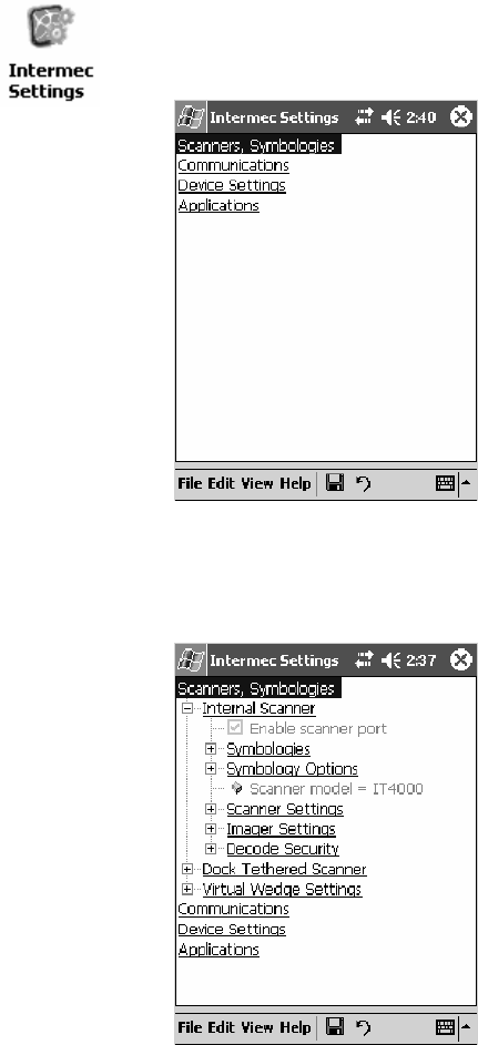
Scanner SupportChapter —6
202 700 Series Color Mobile Computer User’s Manual
Internal Scanners
The Intermec Internal Scanner feature allows Automatic Data Collection
(ADC) by accepting data from the COM1 port and wedging it into the
keyboard interface. You can enable or disable this feature from the Today
screen on the 700 Color Computer.
For Units With PSM Build 3.00 or Newer
Do the following before you configure your internal scanner from the In-
termec Settings control panel applet. Information about the settings you
can configure with this applet is described in the Intermec Computer Com-
mand Reference Manual. The online manual is available from the Intermec
web site at www.intermec.com.
1From the 700 Color Computer, tap Start >Settings >theSystem tab >
the Intermec Settings icon.
2Tap the Scanners, Symbologies option, then tap (+) to expand Internal
Scanner.This sample screen is for the IT4000 scan engine.

6 Scanner Support—Chapter
203700 Series Color Mobile Computer User’s Manual
Scanner and Imager Settings
Depending on what is selected as the scanner model, image settings, de-
code security, scanner settings, and virtual wedge are configured from the
Intermec Settings applet. See the the Intermec Computer Command Refer-
ence Manual, available from the Intermec web site at www.intermec.com,
for more information about each enabled option.
Internal Scanner Supported Symbologies
See the following table for a guideline and Appendix B, “Bar Code Symbol-
ogies” for more information on each supported symbology:
Symbologies EV10 IT4000 SE900 SE900HS SE900-S6 SE900HS-S6
Code39 XX X X X X
UPC/EAN X X X X X X
Code 128 XX X X X X
Interleaved 2 of 5 X X X X X X
Code 93 XX X X X X
Codabar X X X X X X
Code 2 of 5 XX X X X X
MSI X X X X X X
Plessey XX X X X X
Code 11 X X X X X X
Matrix 2 of 5 XX X X X X
Telepen X X X X X X
PDF417 XX X X X X
Micro PDF417 X X X X X X
MaxiCode X
Data Matrix X
QR Code X
RSS 14 X X X X Available in f/w
Sxxp304
Available in f/w
Sxxp304
RSS Limited XX X XAvailableinf/w
Sxxp304
Available in f/w
Sxxp304
RSS Expanded X X X X Available in f/w
Sxxp304
Available in f/w
Sxxp304
Codablock A XX X X X X
Codablock F X X X X X X
UCC Composite X
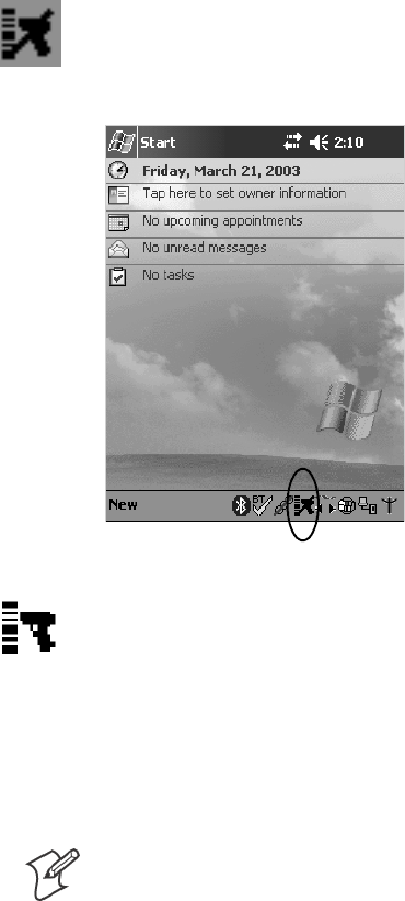
Scanner SupportChapter —6
204 700 Series Color Mobile Computer User’s Manual
Tethered Scanners
The Intermec Tethered Scanner feature allows Automatic Data Collection
(ADC) by accepting data from the COM1 port and wedging it into the
keyboard interface. You can enable or disable this feature from the Today
screen on the 700 Color Computer.
The following information is divided between units with PSM Builds old-
er than 3.00 (next paragraph) or units with PSM Builds 3.00 or newer
(starting on page 209).
For Units With PSM Builds Older than 3.00
Enabling and Disabling
On the 700 Color Computer, tap Start >Today. Tap the bar code scan-
nericonintheSystemTray(circled below). Initially, the bar code scanner
icon indicates that this feature is disabled (shown to the left).
SSelect Comm Port Wedge to send any data, coming into the 700 Color
Computer through the COM1 port from an external input device, as
keyboard data to an application on the desktop.
For example, if you have Pocket Word running on your 700 Color
Computer desktop, information scanned with a scanner connected to
the COM1 port appears in the Word document. If another data collec-
tion application is running and is active on the 700 Color Computer,
the scanned information appears in that application.
Note: When Comm Port Wedge is selected, regardless of the data sent
by the external input device, you cannot control the device or the data
format using any of the Intermec scanner control or data transfer APIs
from the SDK or the internal Data Collection software. The external
inputdeviceisgovernedbywhatsoftwareithasonboardtotellithow
to scan, take pictures, or send the data elsewhere.
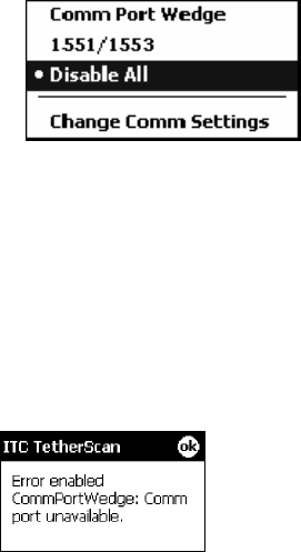
6 Scanner Support—Chapter
205700 Series Color Mobile Computer User’s Manual
SSelect 1551/1553 to enable the Sabre 1551E or 1553 Tethered Scanner
to scan, then send data as keyboard data. The 1551/1553 Tethered
Scanner has software onboard that translates scanned data into charac-
ters, so the running/active application does not need to know how to do
that. All the scanner control and data transfer APIs will work with the
1551/1553 Tethered Scanner, so you can control the device.
SSelect Disable All to disable this feature and use the COM1 port for
another application, such as ActiveSync. An error message will result if
this option were not selected, but this action was attempted. Similarly, if
ActiveSync is using the COM1 port, and you select Comm Port Wedge
or 1551/1553, an error message will result. See “Error Message”for
more information.
Error Message
If the COM1 port is used by another application, such as ActiveSync, nei-
ther the Comm Port Wedge nor the 1551/1553 Tethered Scanner can be
enabled. As a result, the following message may appear. Note that this mes-
sage is for the Comm Port Wedge. You must disable that application to free
uptheCOM1portbeforeyoucanenableeitherthewedgeorthescanner.
Changing Comm Settings
Tap Change Comm Settings to configure the settings for the COM1
port. Current settings are restored after a warm-boot is performed, but are
lost after a cold-boot is performed. When these settings are not changed,
the OK button is disabled (grayed out). When changes are made, tap OK
after it is enabled to accept these changes.
SBaud Rate: 1200, 2400, 4800, 9600, 19200, 38400, 57600,
115200
SData Bits:7or8
SParity: None, Odd, Even, Mark, Space
SStop Bits:1or2
SFlow Control: None or Hardware
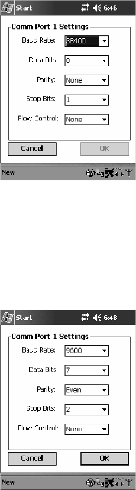
Scanner SupportChapter —6
206 700 Series Color Mobile Computer User’s Manual
Tethered Scanner
Default settings for the Tethered Scanner are shown in this illustration:
Sabre 1551E or 1553 Tethered Scanner
The default communication configuration for the Sabre 1551E or 1553
Tethered Scanner is shown in the following illustration. Scan the EasySet
Reset Factory Defaults label to set the Sabre 1551E or 1553 tethered scan-
ner communications settings to this configuration. The COM1 port con-
figuration settings must also match those of the scanner to scan labels.
Welch Allyn 1470 Imager Settings
You can set the Welch Allyn 1470 Imager to this configuration by scan-
ning the Factory Default Settings label.
6 Scanner Support—Chapter
207700 Series Color Mobile Computer User’s Manual
Scanner Cabling
A null modem cable is required for the Welch Allyn 1470 Imager to com-
municate with the 700 Color Computer when using the 700 Color Serial
Cable (P/N: 226-999-001).
Sabre 1551E / 1553 Cables connect directly to the Model 700 COM Port.
Limitations and Capabilities
The Tethered Scanner has the following limitations:
SNo auto detection of a scanner’s physical connection to COM1 port.
User needs to ensure the communication settings of COM1 port
matched the settings of the device.
SThe Pocket PC Pocket Office applications misbehave when control
characters such as carriage return are wedged. This is a known Pocket
PC problem, which is being worked with Microsoft and for which a
work around is being developed.
SCommunications port is COM1 and cannot be changed.
SA complete bar code label is detected when the time between bytes (the
inter-byte gap) exceeds 100 ms. This allows that data could be concate-
nated if two labels were received while the Comm Port Wedge or the
1551/1553 Tethered Scanner was not performing a read. That is, it
could be wedging data just read or the read thread could be preempted.
Also, the labels could appear concatenated if the scanner itself were to
buffer the labels before transmitting them.
When enabled, the “Comm Port Wedge” menu option has this limitation:
SThereisnobarcodeAPItogetbarcodedatafromthebarcodescan-
ner. The Comm Port Wedge transmits the data through the keyboard
interface only.
When enabled, the “1551/1553” menu option has these capabilities:
SGrid Data Editing is available.
SThe source of the symbology configurations is only available via the
Easy Set command labels. You can only configure the Virtual Wedge
configurations via the Data Collection control panel applet Virtual
Wedge page. See Appendix A, “Configurable Settings,” for information.
SMay transmit the data through the keyboard interface (via the Virtual
Wedge).
Scanner SupportChapter —6
208 700 Series Color Mobile Computer User’s Manual
SThe bar code APIs, defined in the IADC interface, are available to get
barcodedatafromthebarcodescanner.Thefollowingexampleshows
how to programmatically collects bar code data:
#include “IADC.h” // Linked with ITCUUID.LIB
#include “ITCAdcMgmt.h” // Linked with ITCAdcDevMgmt.lib
IADC* pIADC;
HRESULT hrStatus = S_OK;
// Create a ADC COM interface to collect bar code data from the 1551E/1553
// when the 1551/1553 menu option is enabled.
hrStatus =
ITCDeviceOpen(TEXT(“ExtScanner”), // Name of the ADC device.
IID_IADC, // COM interface to return
ITC_DHDEVFLAG_READAHEAD, // Device’s Flags
(LPVOID *) &pIADC); // the returned interface
if( SUCCEEDED(hrStatus) )
{BYTE byteBuffer[MAX_LABEL_SIZE];
DWORD dwLength = 0;
HRESULT hr = pIDC->Read(
byteBuffer, // Buffer to put the ADC data.
MAX_LABEL_SIZE, // Size of pDataBuffer in bytes.
&dwLength, // Number bytes returned.
NULL, // Time stamp of the received data. NULL.
INFINITE // Number of milliseconds to wait.
);
}when done using this COM interface, delete it:
ITCDeviceClose( (IUnknown **) pIADC);
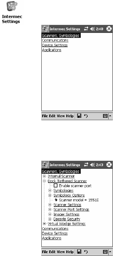
6 Scanner Support—Chapter
209700 Series Color Mobile Computer User’s Manual
For Units With PSM Build 3.00 or Newer
Configuring the Tethered Scanner
Do the following before you configure your tethered scanner from the In-
termec Settings control panel applet. Information about the settings you
can configure with this applet is described in the Intermec Computer Com-
mand Reference Manual. The online manual is available from the Intermec
web site at www.intermec.com.
1Connect your tethered scanner to the tethered scanner port.
2From the 700 Color Computer, tap Start >Settings >theSystem tab >
the Intermec Settings icon.
3Tap the Scanners, Symbologies option, then tap (+) to expand Dock
Tethered Scanner.
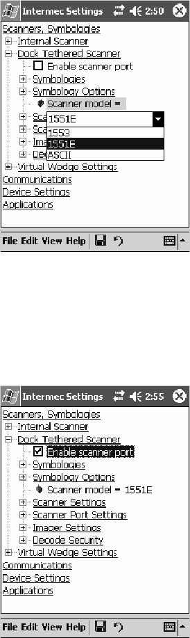
Scanner SupportChapter —6
210 700 Series Color Mobile Computer User’s Manual
4Tap Scanner model for a drop-down list, then select the applicable
scanner, such as “1551E” or “1553” in this sample screen.
5Make sure a scanner is connected to your 700 Computer properly.
Then, tap to check Enable scanner port,thentapFile >Save Settings
from the bottom of the screen. These changes take several moments to
reset.
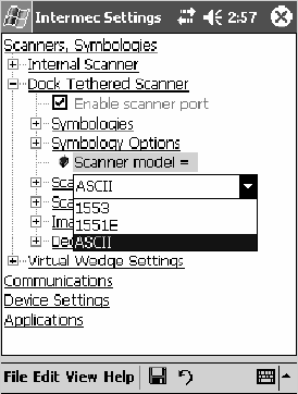
6 Scanner Support—Chapter
211700 Series Color Mobile Computer User’s Manual
1551E or 1553 Selected for Scanner Model
When “1551E” or “1553” is selected from the Scanner model option (see
step 4 above), and the port state is already enabled (see step 5),theprocess
will take several moments to reset. When 1551E or 1553 is successfully
connected during this step, the unit will emit some beeps. Here, the termi-
nal is initializing the scanner at 9600 for the baud rate, 7 data bits, even
parity, and 2 stop bits and synchronizing the terminal’s configuration with
the attached scanner.
With “1551E” or “1553” selected, Symbologies, Symbology Options,
Hardware Trigger, and Scanner Port settings are configured from the In-
termec Settings applet. See the the Intermec Computer Command Reference
Manual, available from the Intermec web site at www.intermec.com, for
more information about each enabled option.
ASCII Selected for Scanner Model
To send data coming into the 700 Color Computer through the COM1
port from an external input device, as keyboard data to an application on
the desktop, do the following:
1Select “ASCII” from the Scanner model option.
2Tap to check Enable scanner port.
3Tap File >Save Settings from the bottom of the screen.
With “ASCII” selected, Symbology Options, Hardware Trigger, and Scan-
ner Port settings are configured from the Intermec Settings applet. See the
the Intermec Computer Command Reference Manual,availablefromtheIn-
termec web site at www.intermec.com, for more information about each
enabled option.

Scanner SupportChapter —6
212 700 Series Color Mobile Computer User’s Manual
Note: When selecting either the 1551E or the 1553 Scanner or enabling
the scanner port for these scanners, the 700 Computer tries to communi-
cate with the attached scanner. If the scanner is not powered, if the cable is
not connected properly, the wrong cable is used, or if the scanner firmware
is older than 2.0, and the “Failed to save one or more settings” message
appears, then this step failed.
This process can take time as the terminal is going through a group of
RS-232 settings to communicate with the scanner. After successful com-
municated with the scanner (about eight beeps are generated), it initializes
the scanner with the 700 Computer’s current settings. This process might
generate a series of beeps pending on the firmware version installed in the
scanner. These beeps are suppressed in firmware versions 2.08 or greater.
Troubleshooting the 1551E/1553 Tethered Scanner
Do the following to troubleshoot your 1551/1553 Tethered Scanner:
1Ensure the correct cable is used for the scanner on the tethered scanner
port. Note the 700 Computer cannot supply power to the scanner.
2Perform a quick test to determine whether the connection is good.
Temporary select the scanner model as “ASCII,” then enable the scan-
ner port state. Go to a command prompt or a notepad and scan a data
label. If a label is wedged into the command prompt or notepad, then
the connection is good.
3If step 2 passes, reset the scanner configurations to their defaults (scan
the Reset Factory Defaults label on the next page) to prevent miscom-
munication, then reenable the scanner port state.
4If step 2 fails, then the firmware installed in the tethered scanner may be
older than version 2.0. Upgrade your scanner firmware.
Reset Factory Defaults
Scan the EasySet software bar code label “Reset Factory Default” to restore
all of your scanner’s configurations to their factory defaults. When this
command label is scanned, reinitialize the tethered scanner (such as disable
the scanner port state, then enable it) on the 700 Computer. Otherwise,
the online configuration and scanning on the 700 Computer are not func-
tional. In general, scan this label only to initially reset the scanner.
Do not scan EasySet command labels to change the following settings:
SSymbologies code mark SCode 128, EAN29 Identifier
SPreamble and Postamble SEnable/Disable symbologies
SSymbology ID transmit option
In some cases, scanning EasySet Command labels cause the current setting
on the user interface to be out of sync with the scanner settings. However,
in some cases, scanning these labels does corrupt scanned data.
The “Open COMx error: 0x00000037” message appears if the COM port
cannot open due to another application using the port. Disable that ap-
plication to free up the COM1 port before you can enable the scanner. “x”
istheCOMportnumber,suchas1,2,or3.

6 Scanner Support—Chapter
213700 Series Color Mobile Computer User’s Manual
Tethered Scanner Supported Symbologies
The user interface may allow configuration of PDF417, Micro PDF417,
RSS, and Codablock bar code symbologies. However, these symbologies
are dependant on what scanner models and firmware versions are in use.
See the following table for a guideline and Appendix B, “Bar Code Symbol-
ogies” for more information on each supported symbology:
You can use a generic ASCII scanner with the 700 Color Computer.
Pending on the scanner, linear symbologies such as Code39, should de-
code correctly. However, 2D symbologies such as PDF417 may not de-
code correctly.
Symbologies 1551E 1553
Code39 XX
UPC/EAN X X
Code 128 XX
Interleaved 2 of 5 X X
Code 93 XX
Codabar X X
Code 2 of 5 XX
MSI X X
Plessey XX
Code 11 X X
Matrix 2 of 5 XX
Telepen X X
PDF417 Available in 1551 0808 PDF
Micro PDF417 Available in 1551 0808 PDF, Sxxp217_ or later
MaxiCode
Data Matrix
QR Code
RSS 14 F/w version 2.15 or later F/w version 2.15 or later
RSS Limited F/w version 2.15 or later F/w version 2.15 or later
RSS Expanded F/w version 2.15 or later F/w version 2.15 or later
Codablock A Available in 1551 0808 PDF
Codablock F Available in 1551 0808 PDF
UCC Composite
Scanner SupportChapter —6
214 700 Series Color Mobile Computer User’s Manual

215700 Series Color Mobile Computer User’s Manual
Programming
7
The following programming information pertains to the 700 Series Color
Mobile Computer:
SCreating CAB Files (page 216)
SCustomization and Lockdown (page 233)
SFTP Server (page 234)
SKernel I/O Control Functions (page 242)
SNetwork Selection APIs (page 258)
SNotifications (page 281)
SReboot Functions (page 283)
SRemapping the Keypad (page 284)
Note: “700 Color” pertains to 740, 741, 750, 751, 760, and 761 Com-
puters unless otherwise noted.
ProgrammingChapter —7
216 700 Series Color Mobile Computer User’s Manual
Creating CAB Files
The Windows CE operating system uses a .CAB file to install an applica-
tion on a Windows CE-based device. A .CAB file is composed of multiple
files that are compressed into one file. Compressing multiple files into one
file provides the following benefits:
SAll application files are present.
SA partial installation is prevented.
SThe application can be installed from several sources, such as a desktop
computer or a Web site.
Use the CAB Wizard application (CABWIZ.EXE) to generate a .CAB file
foryourapplication.
Creating Device-Specific CAB Files
Do the following to create a device-specific .CAB file for an application, in
the order provided:
1Create an .INF file with Windows CE-specific modifications (page
216).
2Optional Create a SETUP.DLL file to provide custom control of the
installation process (page 228).
3UsetheCABWizardtocreatethe.CABfile,usingthe.INFfile,the
optional SETUP.DLL file, and the device-specific application files as
parameters (page 231).
Creating an .INF File
An .INF file specifies information about an application for the CAB Wi-
zard. Below are the sections of an .INF file:
[Version]
This specifies the creator of the file, version, and other relevant informa-
tion.
Required? Yes
SSignature:“signature_name”
“$Windows NT$”
SProvider:“INF_creator”
The company name of the application, such as “Microsoft.”
SCESignature
“$Windows CE$”
Example
[Version]
Signature = “$Windows NT$”
Provider = “Intermec”
CESignature = “$Windows CE$”
Programming—Chapter 7
217700 Series Color Mobile Computer User’s Manual
[CEStrings]
This specifies string substitutions for the application name and the default
installation directory.
Required? Yes
SAppName:app_name
Name of the application. Other instances of %AppName% in the .INF
file are replaced with this string value, such as RP32.
SInstallDir:default_install_dir
Default installation directory on the device. Other instances of %Install-
Dir% in the .INF file are replaced with this string value. Example:
\SDMMC_Disk\%AppName%
Example
[CEStrings]
AppName=“Game Pack”
InstallDir=%CE1%\%AppName%
[Strings]
This section is optional and defines one or more string keys. A string key
represents a string of printable characters.
Required? No
Sstring_key:value
String consisting of letters, digits, or other printable characters. Enclose
value in double quotation marks ““”” if the corresponding string key is
used in an item that requires double quotation marks. No string_keys is
okay.
Example
[Strings]
reg_path = Software\Intermec\My Test App
ProgrammingChapter —7
218 700 Series Color Mobile Computer User’s Manual
[CEDevice]
Describes the platform for the targeted application. All keys in this section
are optional. If a key is nonexistent or has no data, Windows CE does not
perform any checking with the exception being UnsupportedPlatforms.If
the UnsupportedPlatforms key exists but no data, the previous value is not
overridden.
Required? Yes
SProcessorType :processor_type
The value that is returned by SYSTEMINFO.dwProcessorType.For
example, the value for the ARM CPU is 2577
SUnsupportedPlatforms:platform_family_name
This lists known unsupported platform family names. If the name
specified in the [CEDevice.xxx] section is different from that in the
[CEDevice] section, both platform_family_name values are unsupported
for the microprocessor specified by xxx. That is, the list of unsupported
platform family names is appended to the previous list of unsupported
names. Application Manager will not display the application for an
unsupported platform. Also, a user will be warned during the setup
process if the .CAB file is copied to an unsupported device.
Example
[CEDevice]
UnsupportedPlatforms = pltfrm1 ; pltfrm1 is unsupported
[CEDevice.SH3]
UnsupportedPlatforms = ; pltfrm1 is still unsupported
SVersionMin:minor_version
Numeric value returned by OSVERSIONINFO.dwVersionMinor. The
.CAB file is valid for the currently connected device if the version of
this device is greater than or equal to VersionMin.
SVersionMax:major_version
Numeric value returned by OSVERSIONINFO.dwVersionMajor. The
.CAB file is valid for the currently connected device if the version of
this device is less than or equal to VersionMax.
SBuildMin:build_number
Numeric value returned by OSVERSIONINFO.dwBuildNumber. The
.CAB file is valid for the currently connected device if the version of
this device is greater than or equal to BuildMin.
SBuildMax:build_number
Numeric value returned by OSVERSIONINFO.dwBuildNumber. The
.CAB file is valid for the currently connected device if the version of
this device is less than or equal to BuildMax.

Programming—Chapter 7
219700 Series Color Mobile Computer User’s Manual
Example
The following code example shows three [CEDevice] sections: one that
gives basic information for any CPU and two that are specific to the SH3
and the MIPS microprocessors.
[CEDevice] ; A “template” for all platforms
UnsupportedPlatforms = pltfrm1 ; Does not support pltfrm1
; The following specifies version 1.0 devices only.
VersionMin = 1.0
VersionMax = 1.0
[CEDevice.ARM] ; Inherits all [CEDevice] settings
; This will create a .CAB file specific to ARM devices.
ProcessorType = 2577 ; ARM .cab file is valid for ARM microprocessors.
UnsupportedPlatforms = ; pltfrm1 is still unsupported
; The following overrides the version settings so that no version checking is
performed.
VersionMin =
VersionMax =
[CEDevice.MIPS] ; Inherits all [CEDevice] settings
; This will create a .CAB file specific to “MIPS” devices.
ProcessorType = 4000 ; MIPS .CAB file is valid for MIPS
microprocessor.
UnsupportedPlatforms =pltfrm2 ; pltfrm1,pltfrm2 unsupported for MIPs .CAB
file.
Note:TocreatethetwoCPU-specific.CABfilesfortheSETUP.INFfile
in the previous example, run the CAB Wizard with the “/cpu arm mips”
parameter.
ProgrammingChapter —7
220 700 Series Color Mobile Computer User’s Manual
[DefaultInstall]
This describes the default installation of your application. Note that under
this section, you will list items expanded upon later in this description.
Required? Yes
SCopyfiles:copyfile_list_section
Maps to files defined later in the .INF file, such as Files.App, Files.Font,
and Files.Bitmaps.
SAddReg:add_registry_section
Example: RegSettings.All
SCEShortcuts:shortcut_list_section
String that identifies one more section that defines shortcuts to a file, as
defined in the [CEShortcuts] section.
SCESetupDLL:setup_DLL
Optimal string that specifies a SETUP.DLL file. It is written by the In-
dependent Software Vendor (ISV) and contains customized functions
for operations during installation and removal of the application. The
file must be specified in the [SourceDisksFiles] section.
SCESelfRegister:self_reg_DLL_filename
String that identifies files that self-register by exporting the DllRegister-
Server and DllUnregisterServer Component Object Model (COM)
functions. Specify these files in the [SourceDiskFiles] section. During
installation, if installation on the device fails to call the file’s exported
DllRegisterServer function, the file’s exported DllUnregisterServer
function will not be called during removal.
Example
[DefaultInstall]
AddReg = RegSettings.All
CEShortcuts = Shortcuts.All
[SourceDiskNames]
This section describes the name and path of the disk on which your ap-
plication resides.
Required? Yes
Sdisk_ordinal:disk_label,,path
1=,“App files” , C:\Appsoft\RP32\...
2=,“Font files”,,C:\RpTools\...
3=,“CE Tools” ,,C:\windows ce tools...
SCESignature: “$Windows CE$”
Example
[SourceDisksNames] ; Required section
1 = ,“Common files”,,C:\app\common ; Using an absolute path
[SourceDisksNames.SH3]
2 = ,“SH3 files”,,sh3 ; Using a relative path
[SourceDisksNames.MIPS]
2 = ,“MIPS files”,,mips ; Using a relative path

Programming—Chapter 7
221700 Series Color Mobile Computer User’s Manual
[SourceDiskFiles]
This describes the name and path of the files in which your application
resides.
Required? Yes
Sfilename:disk_number[,subdir]
RPM.EXE = 1,c:\appsoft\...
WCESTART.INI = 1
RPMCE212.INI = 1
TAHOMA.TTF = 2
Note:[,subdir] is relative to the location of the INF file.
Example
[SourceDisksFiles] ; Required section
begin.wav = 1
end.wav = 1
sample.hlp = 1
[SourceDisksFiles.SH3]
sample.exe = 2 ; Uses the SourceDisksNames.SH3 identification of 2.
[SourceDisksFiles.MIPS]
sample.exe = 2 ; Uses the SourceDisksNames.MIPS identification of 2.
ProgrammingChapter —7
222 700 Series Color Mobile Computer User’s Manual
[DestinationDirs]
This describes the names and paths of the destination directories for the
application on the target device. Note Windows CE does not support directo-
ry identifiers.
Required? Yes
Sfile_list_section:0,subdir
String that identifies the destination directory. The following list shows
the string substitutions supported by Windows CE. Use these only for
the beginning of the path. \
%CE1% \Program Files
%CE2% \Windows
%CE3% \My Documents
%CE4% \Windows\Startup
%CE5% \My Documents
%CE6% \Program Files\Accessories
%CE7% \Program Files\Communication
%CE8% \Program Files\Games
%CE9% \Program Files\Pocket Outlook
%CE10% \Program Files\Office
%CE11% \Windows\Start Menu\Programs
%CE12% \Windows\Start Menu\Programs\Accessories
%CE13% \Windows\Start Menu\Programs\Communications
%CE14% \Windows\Start Menu\Programs\Games
%CE15% \Windows\Fonts
%CE16% \Windows\Recent
%CE17% \Windows\Start Menu
%InstallDir%
Contains the path to the target directory selected during installation. It
is declared in the [CEStrings] section
%AppName%
Contains the application name defined in the [CEStrings] section.
Example
[DestinationDirs]
Files.Common = 0,%CE1%\My Subdir ; \Program Files\My Subdir
Files.Shared = 0,%CE2% ; \Windows

Programming—Chapter 7
223700 Series Color Mobile Computer User’s Manual
[CopyFiles]
This section, under the [DefaultInstall] section, describes the default files
to copy to the target device. Within the [DefaultInstall] section, files were
listed that must be defined elsewhere in the INF file. This section identi-
fies that mapping and may contain flags.
Required? Yes
Scopyfile_list_section:destination_filename,[source_filename]
The source_filename parameter is optional if it is the same as destina-
tion_filename.
Scopyfile_list_section:flags
Thenumericvaluethatspecifiesanactiontobedonewhilecopyingfi-
les. The following table shows values supported by Windows CE.
Flag Value Description
COPYFLG_WARN_IF_SKIP 0x00000001 Warn user if skipping a file is attempted after error.
COPYFLG_NOSKIP 0x00000002 Do not allow a user to skip copying a file.
COPYFLG_NO_OVERWRITE 0x00000010 Do not overwrite files in destination directory.
COPYFLG_REPLACEONLY 0x00000400 Copy the source file to the destination directory only if the
file is already in the destination directory.
CE_COPYFLG_NO_DATE_DIALOG 0x20000000 Do not copy files if the target file is newer.
CE_COPYFLG_NODATECHECK 0x40000000 Ignore date while overwriting the target file.
CE_COPYFLG_SHARED 0x80000000 Create a reference when a shared DLL is counted.
Example
[DefaultInstall.SH3]
CopyFiles = Files.Common, Files.SH3
[DefaultInstall.MIPS]
CopyFiles = Files.Common, Files.MIPS

ProgrammingChapter —7
224 700 Series Color Mobile Computer User’s Manual
[AddReg]
This section, under the [DefaultInstall] section, is optional and describes
the keys and values that the .CAB file adds to the device registry. Within
the [DefaultInstall] section, a reference may have been made to this
section, such as “AddReg=RegSettings.All”. This section defines the
options for that setting.
Required? No
Sadd_registry_section:registry_root_string
String that specifies the registry root location. The following list shows
thevaluessupportedbyWindowsCE.
SHKCR Same as HKEY_CLASSES_ROOT
SHKCU Same as HKEY_CURRENT_USER
SHKLM Same as HKEY_LOCAL_MACHINE
Sadd_registry_section:value_name
Registryvaluename.Ifempty,the“default”registryvaluenameisused.
Sadd_registry_section:flags
Numeric value that specifies information about the registry key. The
following table shows the values that are supported by Window CE.
Flag Value Description
FLG_ADDREG_NOCLOBBER 0x00000002 If the registry key exists, do not overwrite it. Can be used
with any of the other flags in this table.
FLG_ADDREG_TYPE_SZ 0x00000000 REG_SZ registry data type.
FLG_ADDREG_TYPE_MULTI_SZ 0x00010000 REG_MULTI_SZ registry data type. Value field that follows
can be a list of strings separated by commas.
FLG_ADDREG_TYPE_BINARY 0x00000001 REG_BINARY registry data type. Value field that follows
must be a list of numeric values separated by commas, one
byte per field, and must not use the 0x hexadecimal prefix.
FLG_ADDREG_TYPE_DWORD 0x00010001 REG_DWORD data type. The noncompatible format in the
Win32 Setup .INF documentation is supported.
Example
AddReg = RegSettings.All
[RegSettings.All]
HKLM,%reg_path%,,0x00000000,alpha ; <default> = “alpha”
HKLM,%reg_path%,test,0x00010001,3 ; Test = 3
HKLM,%reg_path%\new,another,0x00010001,6 ; New\another = 6
Programming—Chapter 7
225700 Series Color Mobile Computer User’s Manual
[CEShortCuts]
This section, a Windows CE-specific section under the [DefaultInstall]
section, is optional and describes the shortcuts that the installation applica-
tion creates on the device. Within the [DefaultInstall] section, a reference
may have been made to this section, such as “ShortCuts.All”. This section
defines the options for that setting.
Required? No
Sshortcut_list_section:shortcut_filename
String that identifies the shortcut name. It does not require the .LNK
extension.
Sshortcut_list_section:shortcut_type_flag
Numeric value. Zero or empty represents a shortcut to a file; any non-
zero numeric value represents a shortcut to a folder.
Sshortcut_list_section:target_file_path
String value that specifies the destination location. Use the target file
name for a file, such as MyApp.exe, that must be defined in a file copy
list. For a path, use a file_list_section name defined in the [Destination-
Dirs] section, such as DefaultDestDir,orthe%InstallDir% string.
Sshortcut_list_section:standard_destination_path
Optional string value. A standard %CEx% path or %InstallDir%.Ifno
value is specified, the shortcut_list_section name of the current section or
the DefaultDestDir value from the [DestinationDirs] section is used.
Example
CEShortcuts = Shortcuts.All
[Shortcuts.All]
Sample App,0,sample.exe ; Uses the path in DestinationDirs. Sample
App,0,sample.exe,%InstallDir% ; The path is explicitly specified.
Sample .INF File
[Version] ; Required section
Signature = “$Windows NT$”
Provider = “Intermec Technologies Corporation”
CESignature = “$Windows CE$”
;[CEDevice]
;ProcessorType =
[DefaultInstall] ; Required section
CopyFiles = Files.App, Files.Fonts, Files.BitMaps, Files.Intl,
Files.TelecomNcsCE, Files.Windows, Files.Import, Files.Export, Files.Work,
Files.Database, Files.WinCE AddReg = RegSettings.All ;CEShortcuts =
Shortcuts.All
[SourceDisksNames] ; Required section
1 = ,“App files” ,,c:\appsoft\...
2 = ,”Font files” ,,c:\WinNT\Fonts
3 = ,”CE Tools” ,,c:\windows ce tools\wce400\700ie\mfc\lib\x86
[SourceDisksFiles] ; Required section
rpm.exe = 1,C:\Appsoft\program\wce400\WCEX86Rel700
wcestart.ini = 1
ProgrammingChapter —7
226 700 Series Color Mobile Computer User’s Manual
rpmce212.ini = 1
intermec.bmp = 1
rpmlogo.bmp = 1
rpmname.bmp = 1
import.bmp = 1
export.bmp = 1
clock.bmp = 1
printer.bmp = 1
filecopy.bmp = 1
readme.txt = 1
lang_eng.bin = 1
rpmdata.dbd = 1,database\wce1
tahoma.ttf = 2
mfcce212.dll = 3
olece212.dll = 3
olece211.dll = 1,c:\windows ce tools\wce400\NMSD61102.11\mfc\lib\x86
rdm45wce.dll = 1,c:\rptools\rdm45wce\4_50\lib\wce400\wcex86rel
picfmt.dll = 1,c:\rptools\picfmt\1_00\wce400\wcex86rel6110
fmtctrl.dll = 1,c:\rptools\fmtctrl\1_00\wce400\wcex86rel6110
ugrid.dll = 1,c:\rptools\ugrid\1_00\wce400\wcex86rel6110
simple.dll = 1,c:\rptools\pspbm0c\1_00\wce400\wcex86rel
psink.dll = 1,c:\rptools\psink\1_00\wce400\WCEX86RelMinDependency
pslpwce.dll =1,c:\rptools\pslpm0c\1_00\wce400\WCEX86RelMinDependency
npcpport.dll = 1,c:\rptools\cedk\212_03\installable drivers\printer\npcp
;dexcom.dll = 1,c:\rptools\psdxm0c\1_00\x86
ncsce.exe = 1,c:\rptools\ncsce\1_04
nrinet.dll = 1,c:\rptools\ncsce\1_04
[DestinationDirs] ; Required section
;Shortcuts.All = 0,%CE3% ; \Windows\Desktop
Files.App = 0,%InstallDir%
Files.DataBase = 0,%InstallDir%\DataBase
Files.BitMaps = 0,%InstallDir%\Bitmaps
Files.Fonts = 0,%InstallDir%\Fonts
Files.Intl = 0,%InstallDir%\Intl
Files.TelecomNcsCE = 0,%InstallDir%\Telecom\NcsCE
Files.Windows = 0,%InstallDir%\Windows
Files.Import = 0,%InstallDir%\Import
Files.Export = 0,%InstallDir%\Export
Files.Work = 0,%InstallDir%\Work
Files.WinCE = 0,\storage_card\wince
[CEStrings] ; Required section
AppName = Rp32
InstallDir = \storage_card\%AppName%
[Strings] ; Optional section
;[Shortcuts.All]
;Sample App,0,sample.exe ; Uses the path in DestinationDirs.
;Sample App,0,sample.exe,%InstallDir% ; The path is explicitly specified.
[Files.App]
rpm.exe,,,0
rpm.ini,rpmce212.ini,,0
mfcce212.dll,,,0
olece212.dll,,,0
olece211.dll,,,0
rdm45wce.dll,,,0
picfmt.dll,,,0
Programming—Chapter 7
227700 Series Color Mobile Computer User’s Manual
fmtctrl.dll,,,0
ugrid.dll,,,0
simple.dll,,,0
psink.dll,,,0
pslpwce.dll,,,0
npcpport.dll,,,0
;dexcom.dll,,,0
[Files.DataBase]
rpmdata.dbd,,,0
[Files.Fonts]
tahoma.ttf,,,0
[Files.BitMaps]
intermec.bmp,,,0
rpmlogo.bmp,,,0
rpmname.bmp,,,0
import.bmp,,,0
export.bmp,,,0
clock.bmp,,,0
printer.bmp,,,0
filecopy.bmp,,,0
[Files.Intl]
lang_eng.bin,,,0
[Files.TelecomNcsCE]
ncsce.exe,,,0
nrinet.dll,,,0
[Files.Windows]
readme.txt,,,0
[Files.Import]
readme.txt,,,0
[Files.Export]
readme.txt,,,0
[Files.Work]
readme.txt,,,0
[Files.WinCE]
wcestart.ini,,,0
[RegSettings.All]
HKLM,”SOFTWARE\Microsoft\Shell\AutoHide”,,0x00010001,1
; Autohide the taskbar HKLM,”SOFTWARE\Microsoft\Shell\OnTop”,,0x00010001,0
; Shell is not on top
HKLM,”SOFTWARE\Microsoft\Clock”,SHOW_CLOCK,0x00010001,0
; Clock is not on taskbar

ProgrammingChapter —7
228 700 Series Color Mobile Computer User’s Manual
Using Installation Functions in SETUP.DLL
SETUP.DLL is an optional file that enables you to perform custom opera-
tions during installation and removal of your application. The following
list shows the functions that are exported by SETUP.DLL.
Install_Init Called before installation begins. Use this function to check the application version when reinstal-
ling an application and to determine if a dependent application is present.
Install_Exit Called after installation is complete. Use this function to handle errors that occur during applica-
tion installation.
Uninstall_Init Called before the removal process begins. Use this function to close the application, if the applica-
tion is running.
Uninstall_Exit Called after the removal process is complete. Use this function to save database information to a
file and delete the database and to tell the user where the user data files are stored and how to rein-
stall the application.
Note;Use[DefaultInstall] >CESelfRegister (page 220) in the .INF file to
point to SETUP.DLL.
After the CAB File Extraction
Cab files that need to cause a warm reset after cab extraction will need to
create the __RESETMEPLEASE__.TXT file in the “\Windows” directory.
The preferred method to create this file is within the DllMain portion of
theSETUP.DLLfile.Itlookslikethis:
#include <windows.h>
#include <Tlhelp32.h>
#include <winioctl.h>
#include <ce_setup.h> // in the public SDK dir
#define IOCTL_TERMINAL_RESET CTL_CODE (FILE_DEVICE_UNKNOWN,FILE_ANY_ACCESS,
2050, METHOD_NEITHER)
BOOL APIENTRY DllMain( HANDLE h, DWORD reason, LPVOID lpReserved )
{return TRUE;
} // DllMain
//************************************************************************
// $DOCBEGIN$
// BOOL IsProcessRunning( TCHAR * pname );
//
// Description: Get process table snapshot, look for pname running.
//
// Arguments: pname - pointer to name of program to look for.
// for example, app.exe.
//
// Returns: TRUE - process is running.
// FALSE - process is not running.
// $DOCEND$
//************************************************************************
BOOL IsProcessRunning( TCHAR * pname )
{HANDLE hProcList;
Programming—Chapter 7
229700 Series Color Mobile Computer User’s Manual
PROCESSENTRY32 peProcess;
DWORD thDeviceProcessID;
TCHAR lpname[MAX_PATH];
if ( !pname || !*pname ) return FALSE;
_tcscpy( lpname, pname );
_tcslwr( lpname );
hProcList = CreateToolhelp32Snapshot( TH32CS_SNAPPROCESS, 0 );
if ( hProcList == INVALID_HANDLE_VALUE ) {
return FALSE;
} // end if
memset( &peProcess, 0, sizeof(peProcess) );
peProcess.dwSize = sizeof(peProcess);
if ( !Process32First( hProcList, &peProcess ) ) {
CloseToolhelp32Snapshot( hProcList );
return FALSE;
} // end if
thDeviceProcessID = 0;
do {
_tcslwr( peProcess.szExeFile );
if ( _tcsstr( peProcess.szExeFile, lpname ) ) {
thDeviceProcessID = peProcess.th32ProcessID;
break;
} // end if
} while ( Process32Next( hProcList, &peProcess ) );
if ( ( GetLastError() == ERROR_NO_MORE_FILES ) && ( thDeviceProcessID == 0
)){
CloseToolhelp32Snapshot( hProcList );
return FALSE;
} // end if
CloseToolhelp32Snapshot( hProcList );
return TRUE;
} // IsProcessRunning
codeINSTALL_INIT Install_Init(
HWND hwndParent,
BOOL fFirstCall,
BOOL fPreviouslyInstalled,
LPCTSTR pszInstallDir )
{return codeINSTALL_INIT_CONTINUE;
}
codeINSTALL_EXIT Install_Exit (
HWND hwndParent,
LPCTSTR pszInstallDir,
WORD cFailedDirs,
WORD cFailedFiles,
WORD cFailedRegKeys,
ProgrammingChapter —7
230 700 Series Color Mobile Computer User’s Manual
WORD cFailedRegVals,
WORD cFailedShortcuts )
{HANDLE h;
TCHAR srcfile[MAX_PATH];
TCHAR dstfile[MAX_PATH];
if (cFailedDirs || cFailedFiles || cFailedRegKeys ||
cFailedRegVals || cFailedShortcuts)
return codeINSTALL_EXIT_UNINSTALL;
if ( IsProcessRunning( L”autocab.exe” ) )
{h = CreateFile( L”\\Windows\\__resetmeplease__.txt”,
(GENERIC_READ | GENERIC_WRITE), 0, NULL, CREATE_ALWAYS,
FILE_ATTRIBUTE_HIDDEN, NULL );
if ( h != INVALID_HANDLE_VALUE )
CloseHandle( h );
else
{// Couldn’t create the file. If it failed because the file already
exists, it is not fatal.
// Otherwise, notify user of the inability to reset the device and they
will have to
// perform it manually after all of the installations are complete.
} // end if
}
else
{DWORD dret;
h = CreateFile( L”SYI1:”,
(GENERIC_WRITE | GENERIC_READ), 0, NULL, OPEN_EXISTING,
FILE_ATTRIBUTE_NORMAL, NULL );
// Force a warm start NOW.
if ( h != INVALID_HANDLE_VALUE )
{DeviceIoControl( h, IOCTL_TERMINAL_RESET, NULL, 0, NULL, 0, &dret,
NULL);
// Won’t return, but we’ll show clean up anyway
CloseHandle( h );
}
else
{// Couldn’t access SYSIO. Notify user.
} // end if
} // end if
return codeINSTALL_EXIT_DONE;
}
codeUNINSTALL_INIT
Uninstall_Init(
HWND hwndParent,
LPCTSTR pszInstallDir ) {

Programming—Chapter 7
231700 Series Color Mobile Computer User’s Manual
// TODO: Perform the reverse of INSTALL_INIT here
return codeUNINSTALL_INIT_CONTINUE;
}
codeUNINSTALL_EXIT
Uninstall_Exit(HWND hwndParent) {
// TODO: Perform the reverse of INSTALL_EXIT here
return codeUNINSTALL_EXIT_DONE;
}
The system software looks for the following directory structure and files on
theinstalledmediacardwhetheritbeanSDcardorCFcardorembedded
flash file system. No other folders need exist.
\2577\autorun.exe
\2577\autorun.dat
\2577\autocab.exe
\2577\autocab.dat
\cabfiles\*.cab
Creating CAB Files with CAB Wizard
After you create the .INF file and the optional SETUP.DLL file, use the
CAB Wizard to create the .CAB file. The command-line syntax for the
CABWizardisasfollows:
cabwiz.exe “inf_file” [/dest dest_directory] [/err error_file] [/cpu cpu_type
[cpu_type]]
A batch file, located in <program> directory, with the following com-
mands, works well:
cabwiz.exe c:\appsoft\<program>\<inf_file_name>
cd \appsoft\<program>
“inf_file” The SETUP.INF file path.
dest_directory The destination directory for the .CAB files. If no directory is specified, the .CAB files are created
in the “inf_file” directory.
error_file The file name for a log file that contains all warnings and errors that are encountered when the
.CAB files are compiled. If no file name is specified, errors are displayed in message boxes. If a file
name is used, the CAB Wizard runs without the user interface (UI); this is useful for automated
builds.
cpu_type Creates a .CAB file for each specified microprocessor tag, which is a label used in the Win32 SE-
TUP.INF file to differentiate between different microprocessor types. The /cpu parameter, fol-
lowed by multiple cpu_type values, must be the last qualifier in the command line.
Example
This example creates .CAB files for the ARM and MIPS microprocessors,
assuming the Win32 SETUP.INF file contains the ARM and MIPS tags:
cabwiz.exe “c:\myfile.inf” /err myfile.err /cpu arm mips
Note: CABWIZ.EXE, MAKECAB.EXE, and CABWIZ.DDF (Windows
CE files available on the Windows CE Toolkit) must be installed in the
same directory on the desktop computer. Call CABWIZ.EXE using its full
path for the CAB Wizard application to run correctly.
ProgrammingChapter —7
232 700 Series Color Mobile Computer User’s Manual
Troubleshooting the CAB Wizard
To identify and avoid problems that might occur when using the CAB
Wizard, follow these guidelines:
SUse %% for a percent sign (%) character when using this character in
an .INF file string, as specified in Win32 documentation. This will not
work under the [Strings] section.
SDo not use .INF or .CAB files created for Windows CE to install ap-
plications on Windows-based desktop platforms.
SEnsure the MAKECAB.EXE and CABWIZ.DDF files, included with
Windows CE, are in the same directory as CABWIZ.EXE.
SUse the full path to call CABWIZ.EXE.
SDo not create a .CAB file with the MAKECAB.EXE file included with
Windows CE. You must use CABWIZ.EXE, which uses
MAKECAB.EXE to generate the .CAB files for Windows CE.
SDo not set the read-only attribute for .CAB files.

Programming—Chapter 7
233700 Series Color Mobile Computer User’s Manual
Customization and Lockdown
Pocket PC (Windows Mobile) is a hardware specification created by
Microsoft Corporation. Devices that wish to carry the Pocket PC logo
must meet the minimum hardware requirements set in the Pocket PC spe-
cification. Manufacturers are free to add extra hardware functionality.
Pocket PC devices also use a specialized version of the CE operating sys-
tem. This operating system is built from Windows CE 4.2 but contains
customizations, most notably the lack of a desktop and the addition of the
Today Screen.
To carry the Pocket PC logo, all devices must be tested at an Independent
Test Laboratory. The ITL testing is done based on Microsoft require-
ments. The test lab then reports the findings back to Microsoft Corpora-
tion and Intermec Technologies. If the 700 Color Computer passed all
tests, Intermec is allowed to ship the device with the Pocket PC logo. Each
time the operating system is modified, Intermec must resubmit to ITL
testing.
This means we cannot change the operating system much and still be a
Pocket PC device. For example, if we remove Word from the Start menu,
thedevicewouldfailITLtestingandwewouldnotbeabletoshipdevices
with the Pocket PC logo.
Although many customers want a Pocket PC device, some customers
would prefer that their users not have access to all of the Pocket PC featu-
res. Intermec cannot customize the operating system in any way but a cus-
tom application can:
Delete items from the Start menu, and Programs folder. These items are just shortcuts in the file system so the ap-
plication is not really being deleted. Cold booting the device will bring these items back so the application will need
toberunoneverycoldboot.
Use the RegFlushKey() API to save a copy of the registry to a storage device. See the 700 Color Management Tools
portion of the Intermec Developer’s Library CD for more information on how to do this. Saving a copy of the registry
restores most system settings in a cold boot situation.
Use the SHFullScreen() API in conjunction with other APIs to make the application take up the entire display and
prevent the start menu from being available.
Remap keys and disable keys on the keypad.
Create a custom SIP.
Make changes to the registry to configure the device.
Should you want your 700 Color Computer to display a full screen, keep
in mind that your computer is Pocket-PC certified by Microsoft Corpora-
tion. Check out resources on programming for the Pocket PC, using the
following links. These give full instructions on how to display full screen.
SInstructions on how to create a full screen application for eVC++ ap-
plications using an SHFullScreen() API:
http://support.microsoft.com/support/kb/articles/Q266/2/44.ASP
SInstructions on how to create a full screen application for eVB applica-
tions also using the SHFullScreen() API:
http://support.microsoft.com/support/kb/articles/Q265/4/51.ASP

ProgrammingChapter —7
234 700 Series Color Mobile Computer User’s Manual
FTP Server
FTP support is provided through the FTP Server application
FTPDCE.EXE (MS Windows CE Versions) which is provided as part the
base system.
FTPDCE is the Internet File Transfer Protocol (FTP) server process. The
server can be invoked from an application or command line. Besides ser-
vicing FTP client requests the FTP Server also send a “network announce-
ment” to notify prospective clients of server availability.
Note: You should consult the RFC959 specification for proper use of
some of these commands at the following URL:
Shttp://www.ietf.org/rfc/rfc959.txt for the text version, or
Shttp://www.w3.org/Protocols/rfc959/ for an html version
Do the following to send commands:
1Start an FTP client and connect to the device FTP server.
2Log in with “intermec” as the user name and “cr52401” for the pass-
word.
3From the FTP client, send the command.
4Wait for a response.
Synopsis
ftpdce [options ]
Options
–Aaddr (where addr is in the form of a.b.c.d) Sets the single target address to which to send the network an-
nouncement. Default is broadcast.
–Bbyte Sets the FTP data block size. Smaller sizes may be useful over slower links. Default is 65536.
–Cname Sets the device name. Used by Intermec management software.
–Fvalue Disables the default Intermec account. A value of “0” disables the account. Default is “1”.
Note that disabling the default account without providing a working access control list on the server
will result in a device that will not accept any FTP connections.
–Hsec Sets the interval between network announcements in seconds.A value of “0” turns the network an-
nouncement off. Default is 30 seconds.
–Iaddr (where addr is in the form of a.b.c.d) Sets the preferred 6920 Communications Server (optional).
–Llog (where log is either “0” or “1”) Sets the state of logging. Default is 0 (disabled).
–Nsec Specifies the number of seconds to wait before initially starting FTP server services.
–Pport Sets the UDP port on which the network announcement will be sent. Default port is 52401.
–Qport Sets the port on which the FTP Server will listen for connections. Defaultportis21.
–Rdir Sets the FTP mount point to this directory. Default is the root folder of the object store.
–Tscrip Sets the script name for the 6920 Communications Server to process.
–Uurl Sets the default URL for this device.
–Z“parms” Sets extended parameters to be included in the network announcement.

Programming—Chapter 7
235700 Series Color Mobile Computer User’s Manual
Configurable Parameters Via the Registry Editor
The following parameters receive default values during the installation of
the Intermec FTP Server components. A few of the parameters are visible
in the registry by default, but most must be created in order to modify the
default behavior of the FTP server.
BlockSize
Setting this parameter configures the Intermec FTP Server to transmit and
receive Ethernet packets using the specified data block size. By default, the
FTP server transmits and receives data using a 64K data block size. Adjust-
ing this value may be useful in certain wireless TCP/IP installations.
Key HKLM\Software\Intermec\IFTP
Value Type REG_DWORD - data block size, in bytes.
Valid Range 0x100-0x10000 (256-65536 decimal).
Default 65536
DeviceName
This parameter configures the Intermec FTP Server to include the speci-
fied device name in the Intermec Device Network Announcement
(IDNA). Adjusting this value may be useful in assigning a symbolic name
to this device for asset tracking.
Key HKLM\Software\Intermec\IFTP
Value Type REG_SZ
Valid Range None.
Default None.
DeviceURL
This parameter configures the Intermec FTP Server to transmit the speci-
fied URL in the IDNA. This can be used by Intermec management soft-
ware for asset management.
Key HKLM\Software\Intermec\IFTP
Value Type REG_SZ
Valid Range None.
Default None.

ProgrammingChapter —7
236 700 Series Color Mobile Computer User’s Manual
IDNATarget
This parameter configures the Intermec FTP Server to transmit the IDNA
to a specific destination instead of a general UDP broadcast. This parame-
ter is useful on networks that do not allow UDP broadcasts to be routed
between subnets. The use of this parameter restricts the reception of the
IDNA to the target destination only.
Key HKLM\Software\Intermec\IFTP
Value Type REG_SZ
Valid Range None.
Default None.
ManifestName
This parameter configures the Intermec FTP Server to transmit the speci-
fied manifest name in the IDNA. This parameter is used by the Intermec
6920 Communications Server for communication transactions. See the
6920 Communications Server documentation for proper use of this pa-
rameter.
Key HKLM\Software\Intermec\IFTP
Value Type REG_SZ
Valid Range None.
Default iftp.ini
PauseAtStartup
This parameter configures the Intermec FTP Server to sleep for the speci-
fied number of seconds before making the FTP service available on the
device.
Key HKLM\Software\Intermec\IFTP
Value Type REG_DWORD - stored in seconds.
Valid Range None.
Default 0
Root
This parameter configures the Intermec FTP Server to set the root of the
FTP mount point to the specified value. Note that this must map to an ex-
isting directory or you will not be able to log into the FTP Server.
Key HKLM\Software\Intermec\IFTP
Value Type REG_SZ
Valid Range None.
Default \

Programming—Chapter 7
237700 Series Color Mobile Computer User’s Manual
Transferring Files Over TCP/IP Networks
The File Transfer Protocol (FTP) server transfers files over TCP/IP net-
works. The FTPDCE.EXE program is a version that does not display a
window, but can run in the background.
FTPDCE is the Internet File Transfer Protocol (FTP) server process. The
server can be invoked from an application or command line. Besides ser-
vicing FTP client requests, the FTP Server also sends a “network an-
nouncement” to notify prospective clients of server availability.
Remarks
The FTP Server currently supports the following FTP requests:
CDUP Changes to the parent directory of the current working directory.
CWD Changes working directory.
DELE Deletes a file.
HELP Gives help information.
LIST (This FTP request is the same as the ls -lgA command). Gives list files in a directory.
MKD Makes a directory.
MODE (AlwaysUsesBinary).Specifies data transfer mode.
NLST (Not supported) Givesanamelistoffilesindirectory(thisFTPrequestisthesameasthels command).
NOOP Does nothing.
PASS Specifies a password.
PWD Prints the current working directory.
QUIT Terminates session.
RETR Retrieves a file.
RMD Removes a directory.
RNFR Specifies rename-from file name.
RNTO Specifies rename-to file name.
STOR Stores a file.
SYST Shows the operating system type of server system.
TYPE (Binary transfers only.) Specifies the data transfer type with the Type parameter.
USER Specifies user name.
XCUP (Not Normally Used) Changes the parent directory of the current working directory.
XCWD (Not Normally Used) Changes the current directory.
XMKD (Not Normally Used) Creates a directory.
XPWD (Not Normally Used) Prints the current working directory.
XRMD (Not Normally Used) Removes a directory.

ProgrammingChapter —7
238 700 Series Color Mobile Computer User’s Manual
SITE The following extended OEM commands are supported by the SITE request. For Microsoft FTP cli-
ents, you can send site commands by preceding the command with “quote” such as “quote site status.”
ATTRIB Gets or sets the attributes of a given file. (SITE ATTRIB)
Usage QUOTE SITE ATTRIB [+R |-R][+A |-A ][+S |-S][+H |-H][[path]
filename]
+Sets an attribute.
–Clears an attribute.
RRead-only file attribute.
AArchive file attribute.
SSystem file attribute.
HHidden file attribute.
To retrieve the attributes of a file, only specify the file. The server response will be:
200-AD SHRCEIX filename
If the flag exists in its position shown above, it is set. Also, in addition to the values
defined above, there is also defined:
CCompressed file attribute.
EEncrypted file attribute.
IINROM file attribute.
XXIPfileattribute(executeinROM,notshadowedinRAM).
BOOT Reboots the server OS. This will cause the system on which the server is executing to
reboot. The FTP Server will shut down cleanly before reboot. All client connections
will be terminated. Cold boot is default except for the PocketPC build in which the
default is warm boot. (SITE BOOT)
Usage: QUOTE SITE BOOT [WARM |COLD]
COPY Copies a file from one location to another. (SITE COPY)
Usage: QUOTE SITE COPY [source][destination]
Example: QUOTE SITE COPY ‘\Storage Card\one.dat’ ‘\Stor-
age Card\two.dat’
EXIT Exits the FTP Server. This command will shut down the FTP Server thus termina-
ting all client connections. (SITE EXIT)
Usage: QUOTE SITE EXIT
HELP Gives site command help information. (SITE HELP)
Usage: QUOTE SITE HELP [command]
KILL Terminates a running program. (SITE KILL)
Usage: QUOTE SITE KILL [program |pid]
LOG Opens or closes the program log. (SITE LOG)
Usage: QUOTE SITE LOG [open [filename]| close]
PLIST Lists the running processes (SITE PLIST)
Usage: QUOTE SITE PLIST
RUN Starts a program running. If the program to run has spaces in path or filename,
wrappingthenamewithsinglequotesisrequired.
Usage: QUOTE SITE RUN [program]
Example: QUOTE SITE RUN ‘\Storage Card\app.exe’

Programming—Chapter 7
239700 Series Color Mobile Computer User’s Manual
STATUS Returns the current settings of the FTP Server. MAC, serial number, model, IP ad-
dress, network announcement information as well as OS memory usage are returned.
(SITE STATUS)
Usage: QUOTE SITE STATUS
TIMEOUT Toggles idle timeout between 120 to 1200 seconds (2 to 20 minutes). If this timer
expires with no activity between the client and the server, the client connection will
be disconnected. If the optional seconds argument is supplied, the server will set the
connection timeout to the number of seconds specified. Default is 120 seconds or 2
minutes. (SITE TIMEOUT)
Usage: QUOTE SITE TIMEOUT [seconds]
EKEY Gives site command electronic key information. (SITE HELP)
Usage: QUOTE SITE EKEY [command]
EVAL Gives site command electronic value information. (SITE HELP)
Usage: QUOTE SITE EVAL [command]
GVAL Gives site command general value information. (SITE HELP)
Usage: QUOTE SITE GVAL [command]
PVAL Gives site command value information. (SITE HELP)
Usage: QUOTE SITE PVAL [command]
The remaining FTP requests specified in RFC 959 are recognized, but not
implemented.
The banner returned in the parenthetical portion of its greeting shows the
version number of the FTP Server as well as the MAC address, serial num-
ber and operating system of the machine hosting the server.
The FTP Server supports browsing from the latest Netscape and Microsoft
web browsers. Drag-and-drop capability is available using this environ-
ment.
The FTPDCMDS subdirectory contains commands to use from the web
browser.
SClick EXITME.BIN to execute a SITE EXIT command.
SClick REBOOTME.BIN to execute SITE BOOT command.
SUse the GET command on these files to have the FTP Server execute
these commands.
SSecurity:
A customer configurable access control list may be installed on the
700 Color Computer. This list will allow customers to restrict access
via the FTP Server to users they wish and is in addition to default
Intermec accounts that are disabled using the -F0 option at runtime.
The access control list is named FTPDCE.TXT and is placed in the
same directory on the 700 Color Computer as the FTPDCE.EXE
server. The FTP Server encrypts this file to keep the information safe
from unauthorized users. This file is encrypted when the FTP Server
is started so a file that is placed onto the 700 Color Computer after
the FTP Server starts will require a restart of the FTP Server to take
effect.
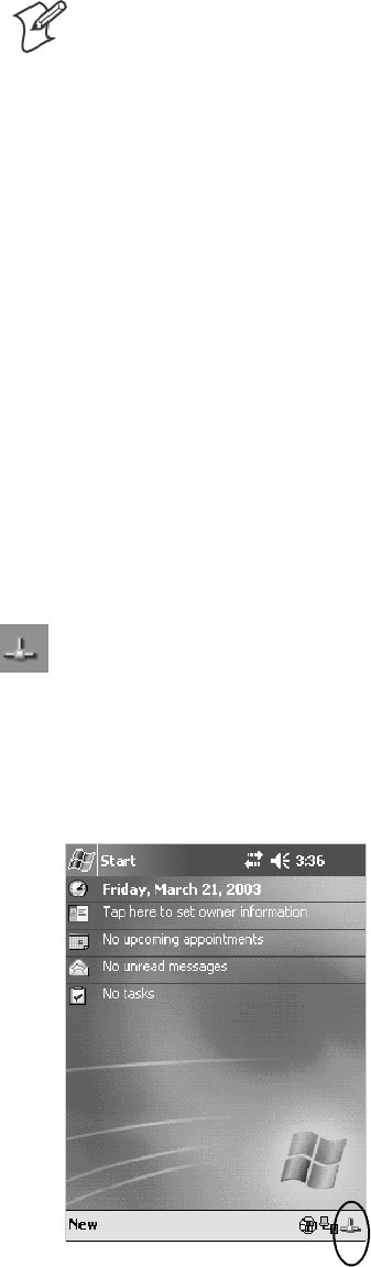
ProgrammingChapter —7
240 700 Series Color Mobile Computer User’s Manual
The format of the FTPDCE.TXT is as follows:
FTPDCE:user1!passwd1<cr><lf>user2!passwd2<cr><lf>user3
!passwd3<cr><lf>...
Note: The user accounts and passwords are case sensitive.
Once the access control list is encrypted on the 700 Color Computer,
the FTP Server hides this file from users. Once an access control list
is installed on the 700 Color Computer, a new one is not accepted by
the FTP Server until the previous one is removed. Encrypted access
control lists are not portable between 700 Color Computers.
Stopping the FTP Server from Your Application
To allow application programmers the ability to programmatically shut
down the FTP Server, the FTP Server periodically tests to see if a named
event is signaled. The name for this event is “ITC_IFTP_STOP” (no
quotes).
For examples on how to use events, consult the Microsoft Developer Net-
work Library at http://www.msdn.com. The MSDN Library is an essential
resource for developers using Microsoft tools, products, and technologies.
It contains a bounty of technical programming information, including
sample code, documentation, technical articles, and reference guides.
Autostart FTP
This automatically starts the FTP Server (FTPDCE.EXE) when the 700
Color Computer is powered on. This is provided with the NDISTRAY
program (the Network Driver Interface Specification tray application),
which displays the popup menu that currently allows you to load and un-
load the network drivers. Tap the antenna icon in the System Tray of the
Today screen (a sample antenna icon is circled below) for this pop-up menu.
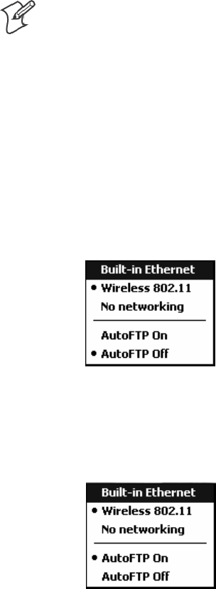
Programming—Chapter 7
241700 Series Color Mobile Computer User’s Manual
The default is to start the FTP Server at boot time, unless the following
registry entry is defined and set to “0” which disables AutoFTP. “1” en-
ablestheAutoFTP.TheentrycanbesetfromtheNDISTRAYpop-up
menu by selecting either AutoFTP On or AutoFTP Off.
HKEY_LOCAL_MACHINE\Software\Intermec\Ndistray\StartupIFTP
These new entries are located below the selections to load the network
drivers. If the StartupIFTP registry key is not defined, the FTP Server is
loaded by default, to provide “out-of-the-box” capability for customers
who want to begin loading files to the 700 Color Computer without any
prior configuration.
Note: If a network driver is unloaded using the NDISTRAY popup menu,
and the FTP Server is running, the FTP Server is stopped.
On a resume, if AutoFTP is enabled and the FTP Server is running, it is
stopped and restarted. NDISTRAY uses a helper application named RESE-
TIFTP to implement the restart on resume feature.
To do an AutoFTP Installation Check:
1Ensure the FTP Server is running “out-of-the-box” the first time.
2Tap Start >Today to access the Today screen, then tap the antenna
icon in the System Tray to bring up the NDISTRAY pop-up menu.
Select AutoFTP Off to disable AutoFTP. Do a warm boot and confirm
the FTP Server is not running.
3Tap Start >Today to access the Today screen, then tap the antenna
icon in the System Tray to bring up the NDISTRAY pop-up menu.
Select AutoFTP On to enable AutoFTP, reboot, confirm it is running.
4Unload the network driver when the FTP Server is running and con-
firm that it is not running any more.
5Load the FTP Server, establish a connection, then suspend and resume.
The server should still run, but the FTP connection to the client should
be dropped.

ProgrammingChapter —7
242 700 Series Color Mobile Computer User’s Manual
Kernel I/O Controls
This describes the KernelIoControl() functions available to application
programmers. Most C++ applications will need to prototype the function
as the following to avoid link and compile errors.
extern “C” BOOL KernelIoControl(DWORD dwIoControlCode, LPVOID lpInBuf, DWORD
nInBufSize, LPVOID lpOutBuf, DWORD nOutBufSize, LPDWORD lpBytesReturned);
IOCTL_HAL_GET_DEVICE_INFO
This IOCTL returns either the platform type or the OEMPLATFORM
namebasedonaninputvalue.
Syntax
BOOL KernelIoControl( IOCTL_HAL_GET_DEVICE_INFO, LPVOID
lpInBuf, DWORD nInBufSize, LPVOID lpOutBuf, DWORD
nOutBufSize, LPDWORD lpBytesReturned );
Parameters
lpInBuf Points to a DWORD containing either the SPI_GETPLAT-
FORMTYPE or SPI_GETOEMINFO value.
lpInBufSize Must be set to sizeof(DWORD).
lpOutBuf Must point to a buffer large enough to hold the return data of the
function. If SPI_GETPLATFORMTYPE is specified in lpInBuf,
then the “PocketPC\0” Unicode string is returned. If SPI_GE-
TOEMINFO is specified in lpInBuf, then the “Intermec 700\0”
Unicode string is returned.
nOutBufSize ThesizeoflpOutBuf in bytes. Must be large enough to hold the
string returned.
lpBytesReturned The actual number of bytes returned by the function for the data
requested.
Return Values
Returns TRUE if function succeeds. Returns FALSE if the function fails.
GetLastError() may be used to get the extended error value.

Programming—Chapter 7
243700 Series Color Mobile Computer User’s Manual
IOCTL_HAL_ITC_READ_PARM
Usage
#include “oemioctl.h”
Syntax
BOOL KernelIoControl( IOCTL_HAL_ITC_READ_PARM,LPVOID
lpInBuf,DWORD nInBufSize,LPVOID lpOutBuf,DWORD
nOutBufSize,LPDWORD lpBytesReturned );
Parameters
lpInBuf Points to this structure. See “ID Field Values”below.
struct PARMS {
BYTE id;
BYTE ClassId;
};
nInBufSize Must be set to the size of the PARMS structure.
lpOutBuf Must point to a buffer large enough to hold the return data of the
function. If this field is set to NULL and nOutBufSize is set to zero
when the function is called the function will return the number
bytes required by the buffer.
nOutBufSize ThesizeoflpOutBuf in bytes.
lpBytesReturned Number of bytes returned by the function for the data requested.
Return Values
Returns TRUE if function succeeds. Returns FALSE if the function fails.
GetLastError() may be used to get the error value. Either
ERROR_INVALID_PARAMETER or
ERROR_INSUFFICIENT_BUFFER may be returned when this function
is used to get the error.
ID Field Values
The id field of the PARMS structure may be one of the following values:
ID Field Values
ITC_NVPARM_ETHERNET_ID
This IOCTL returns the Ethernet 802.11b or 802.11b/g MAC Address. Six bytes are returned in the buffer pointed
to by the lpOutBuffer parameter.
ITC_NVPARM_SERIAL_NUM
This IOCTL returns the serial number of the device in BCD format. Six bytes are returned in the buffer pointed to
by the lpOutBuffer parameter.
ITC_NVPARM_MANF_DATE
This IOCTL returns the device date of manufacture in the BCD YYYY/MM/DD format. Four bytes are returned in
the buffer pointed to by the lpOutBuffer parameter.
ITC_NVPARM_SERVICE_DATE
This IOCTL returns the device’s date of last service in BCD YYYY/MM/DD format. Four bytes are returned in the
buffer pointed to by the lpOutBuffer parameter.

ProgrammingChapter —7
244 700 Series Color Mobile Computer User’s Manual
ID Field Values (continued)
ITC_NVPARM_DISPLAY_TYPE
This IOCTL returns the device’s display type. One byte is returned in the buffer pointed to by the lpOutBuffer
parameter.
ITC_NVPARM_EDG_IP
This IOCTL returns the device Ethernet debug IP address. Four bytes are returned in the buffer pointed to by the
lpOutBuffer parameter.
ITC_NVPARM_EDBG_SUBNET
This IOCTL returns the device Ethernet debug subnet mask. Four bytes are returned in the buffer pointed to by the
lpOutBuffer parameter.
ITC_NVPARM_ECN
This IOCTL returns ECNs applied to the device in a bit array format. Four bytes are returned in the buffer pointed
to by the lpOutBuffer parameter.
ITC_NVPARM_CONTRAST
This IOCTL returns the device default contrast setting. Two bytes are returned in the buffer pointed to by the
lpOutBuffer parameter.
ITC_NVPARM_MCODE
This IOCTL returns the manufacturing configuration code for the device. Sixteen bytes are
returned in the buffer pointed to by the lpOutBuffer parameter.
ITC_NVPARM_VERSION_NUMBER
This IOCTL returns the firmware version for various system components. These values for the ClassId field of the
PARMS structure are allowed when ITC_NVPARM_VERSION_NUMBER is used in the id field:
SVN_CLASS_KBD Returns a five-byte string, including null terminator, that contains an ASCII value which
represents the keypad microprocessor version in the system. The format of the string is x.xx with a terminating null
character.
SVN_CLASS_ASIC Returns a five-byte string, including null terminator, that contains an ASCII value which
represents the version of the FPGA firmware in the system. The format of the string is x.xx with a terminating null
character.
SVN_CLASS_BOOTSTRAP Returns a five-byte string, including null terminator, that contains an ASCII value
which represents the version of the Bootstrap Loader firmware in the system. The format of the string is x.xx with a
terminating null character.
ITC_NVPARM_INTERMEC_SOFTWARE_CONTENT
This IOCTL reads the manufacturing flag bits from the non-volatile data store that dictates certain software
parameters. A BOOLEAN DWORD is returned in the buffer pointed to by lpOutBuffer that indicates if Intermec
ContentisenabledintheXIPregions.TRUEindicatesthatitisenabled.FALSEindicatesthatitisnotenabled.
ITC_NVPARM_ANTENNA_DIVERSITY
This IOCTL reads the state of the antenna diversity flag. A BOOLEAN DWORD is returned in the buffer pointed
to by lpOutBuffer that indicates if there is a diversity antenna installed. TRUE indicates that it is installed. FALSE
indicatesthatitisnotinstalled.
ITC_NVPARM_WAN_RI
This IOCTL reads the state of the WAN ring indicator flag. A BOOLEAN DWORD is returned in the buffer
pointed to by lpOutBuffer that indicates the polarity of the WAN RI signal. TRUE indicates active high. FALSE
indicates active low.

Programming—Chapter 7
245700 Series Color Mobile Computer User’s Manual
ID Field Values (continued)
ITC_NVPARM_RTC_RESTORE
This IOCTL reads the state of the real-time clock restore flag. A BOOLEAN DWORD is returned in the buffer
pointed to by lpOutBuffer. TRUE indicates that the RTC is restored upon a cold boot. FALSE indicates that the
RTC is not restored.
ITC_NVPARM_INTERMEC_DATACOLLECTION_SW
This IOCTL reads the state of the data collection software enabled flag. A BOOLEAN DWORD is returned in the
buffer pointer to by lpOutBuffer that indicates the data collection software is to install at boot time. FALSE indicates
the data collection software should not install.
ITC_NVPARM_INTERMEC_DATACOLLECTION_HW
This IOCTL reads the data collection hardware flags. A BYTE is returned in the buffer pointer to by lpOutBuffer
that indicates the type of data collection hardware installed. The maximum possible value returned is
ITC_DEVID_SCANHW_MAX.
SITC_DEVID_SCANHW_NONE No scanner hardware is installed.
SITC_DEVID_OEM2D_IMAGER OEM 2D imager is installed.
SITC_DEVID_INTERMEC2D_IMAGER Intermec 2D imager is installed.
SITC_DEVID_SE900_LASER SE900 laser is installed.
SITC_DEVID_SE900HS_LASER SE900HS laser is installed.
SITC_DEVID_INTERMEC_EVIO EVIO linear imager is installed.
The high bit indicates whether the S6 scanning engine is installed. The bit mask for this is
ITC_DEVID_S6ENGINE_MASK. A non-zero value indicates that the S6 scanning engine is installed.
ITC_NVPARM_WAN_INSTALLED
This IOCTL reads the state of the WAN radio installed flag. A BOOLEAN DWORD is returned in the buffer
pointed to by lpOutBuffer. TRUE indicates that the WAN radio is installed. FALSE indicates that no WAN radio is
installed.
ITC_NVPARM_WAN_FREQUENCY
This IOCTL reads the state of the WAN radio frequency flag. A BOOLEAN DWORD is returned in the buffer
pointed to by lpOutBuffer. TRUE indicates that the WAN radio frequency is United States. FALSE indicates that
the WAN radio frequency is European.
ITC_NVPARM_WAN_RADIOTYPE
This IOCTL reads the WAN radio ID installed by manufacturing. A BYTE is returned in the buffer pointer to by
lpOutBuffer whichindicatesthetypeofWANradiohardwareinstalled.Themaximumpossiblevaluereturnedis
ITC_DEVID_WANRADIO_MAX. The current definitions are:
SITC_DEVID_WANRADIO_NONE No WAN radio installed.
SITC_DEVID_WANRADIO_SIERRA_SB555 CDMA Sierra Wireless radio.
SITC_DEVID_WANRADIO_XIRCOM_GEM3503 GSM/GPRS Intel (Xircom) radio.
SITC_DEVID_WANRADIO_SIEMENS_MC45 GSM/GPRS Siemens radio.
SITC_DEVID_WANRADIO_SIEMENS_MC46 GSM/GPRS Siemens radio.
ITC_NVPARM_80211_INSTALLED
This IOCTL reads the state of the 802.11b or 802.11b/g radio installed flag. A BOOLEAN DWORD is returned in
the buffer pointed to by lpOutBuffer. TRUE indicates that the 802.11b or 802.11b/g radio is installed. FALSE
indicates that no 802.11b or 802.11b/g radio is installed.
ITC_NVPARM_80211_RADIOTYPE
This IOCTL reads the 802.11b or 802.11b/g radio ID installed by manufacturing. A BYTE is returned in the buffer
pointer to by lpOutBuffer that indicates the type of 802.11b or 802.11b/g radio hardware installed. The maximum
possible value returned is ITC_DEVID_80211RADIO_MAX. The current definitions are:
SITC_DEVID_80211RADIO_NONE No 802.11b or 802.11b/g radio installed.
SITC_DEVID_80211RADIO_INTEL_2011B Intel 2011B radio installed.

ProgrammingChapter —7
246 700 Series Color Mobile Computer User’s Manual
ID Field Values (continued)
ITC_NVPARM_BLUETOOTH_INSTALLED
This IOCTL reads the state of the Bluetooth radio installed flag. A BOOLEAN DWORD is returned in the buffer
pointed to by lpOutBuffer. TRUE indicates that the Bluetooth radio is installed. FALSE indicates that no Bluetooth
radio is installed.
ITC_NVPARM_SERIAL2_INSTALLED
This IOCTL reads the state of the serial 2 (COM2) device installed flag. A BOOLEAN DWORD is returned in the
buffer pointed to by lpOutBuffer. TRUE indicates that the serial 2 device is installed. FALSE indicates that no serial
2 device is installed.
ITC_NVPARM_VIBRATE_INSTALLED
This IOCTL reads the state of the vibrate device installed flag. A BOOLEAN DWORD is returned in the buffer
pointed to by lpOutBuffer. TRUE indicates that the vibrate device is installed. FALSE indicates that no vibrate
device is installed.
ITC_NVPARM_LAN9000_INSTALLED
This IOCTL reads the state of the Ethernet device installed flag. A BOOLEAN DWORD is returned in the buffer
pointed to by lpOutBuffer. TRUE indicates that the Ethernet device is installed. FALSE indicates that no Ethernet
device is installed.
ITC_NVPARM_SIM_PROTECT_HW_INSTALLED
This IOCTL reads the state of the SIM card protection hardware installed flag. A BOOLEAN DWORD is returned
in the buffer pointed to by lpOutBuffer. TRUE indicates that the SIM card protection hardware is installed. FALSE
indicates that no SIM card protection hardware is installed.
ITC_NVPARM_SIM_PROTECT_SW_INSTALLED
This IOCTL reads the state of the SIM card protection software installed flag. A BOOLEAN DWORD is returned
in the buffer pointed to by lpOutBuffer. TRUE indicates that the SIM card protection software is installed. FALSE
indicates that no SIM card protection software is installed.

Programming—Chapter 7
247700 Series Color Mobile Computer User’s Manual
IOCTL_HAL_ITC_WRITE_SYSPARM
Describes and enables the registry save location.
Usage
#include “oemioctl.h”
Syntax
BOOL KernelIoControl( IOCTL_HAL_ITC_WRITE_SYSPARM,LPVOID
lpInBuf,DWORD nInBufSize, LPVOID lpOutBuf, DWORD
nOutBufSize, LPDWORD lpBytesReturned );
Parameters
lpInBuf Asinglebytethatmaybeoneoftheid values. See “ID Field Values”
on the next page.
nInBufSize Must be set to the size of the lpInBuf in bytes.
lpOutBuf Must point to a buffer large enough to hold the data to be written
to the non-volatile data store.
nOutBufSize ThesizeoflpOutBuf in bytes.
lpBytesReturned The number of bytes returned by the function.
Return Values
Returns TRUE if function succeeds. Returns FALSE if the function fails.
GetLastError() may be used to get the error value. Either
ERROR_INVALID_PARAMETER or
ERROR_INSUFFICIENT_BUFFER may be returned when this function
is used to get the error.

ProgrammingChapter —7
248 700 Series Color Mobile Computer User’s Manual
ID Field Values
The id field of lpInBuf may be one of the following values:
ID Field Values
ITC_REGISTRY_SAVE_ENABLE
This function enables or disables the save registry to non-volatile media feature of the RegFlushKey() function.
lpOutBuf mustbesettozero(FALSE)ifthefeatureistobedisabledorone(TRUE)ifthefeatureistobeenabled.
ITC_ DOCK_SWITCH
This IOCTL sets a position of the dock switch. The dock switch may be set to either “modem” or “serial” positions.
lpOutBuf must point to a buffer that contains a byte value of either DOCK_MODEM or DOCK_SERIAL as
defined in OEMIOCTL.H; the value specifies the position the switch is to be set. The call appears as follows:
// port = DOCK_MODEM or DOCK_SERIAL as defined in oemioctl.h
BOOL SetDockSwitch( BYTE port)
{
DWORD cmd = ITC_DOCK_SWITCH;
DWORD cbRet;
return KernelIoControl(IOCTL_HAL_ITC_WRITE_SYSPARM,&cmd, sizeof(cmd),
&port,sizeof(port),&cbRet)
}
ITC_ WAKEUP_MASK
This IOCTL sets a bit mask that represents the mask for the five programmable wakeup keys. The I/O key is not a
programmable wakeup key. By default it is always the system resume key and all other keys are set to disable key
wakeup. A zero in a bit position masks the wakeup for that key. A one in a bit position enables wakeup for that key.
lpOutBuf must point to a buffer that contains a byte value of a wakeup mask consisting of the OR’ed constants as
definedinOEMIOCTL.H.Onlythefollowingkeysareprogrammableaswakeupevents.
#define SCANNER_TRIGGER 1
#define SCANNER_LEFT 2
#define SCANNER_RIGHT 4
#define GOLD_A1 8
#define GOLD_A2 0x10
ITC_AMBIENT_KEYBOARD (does not apply to the 730 Computer)
This IOCTL sets the threshold for the keypad ambient sensor. This can be a value from 0 (always off) to 255 (always
on). lpOutBuf must point to a buffer that contains a byte value of the desired setting.
ITC_AMBIENT_FRONTLIGHT (does not apply to the 730 Computer)
This IOCTL sets the threshold for the frontlight ambient sensor. This can be a value from 0 (always off) to 255.
lpOutBuf must point to a buffer that contains a byte value of the desired setting.

Programming—Chapter 7
249700 Series Color Mobile Computer User’s Manual
IOCTL_HAL_GET_DEVICEID
This IOCTL returns the device ID. There are two types of device IDs
supported,whicharedifferentiatedbasedonthesizeoftheoutput buffer.
TheUUIDisreturnedifthebuffersizeissetto
sizeof(UNIQUE_DEVICEID),otherwisetheoldstyledeviceIDisre-
turned.
Usage
#include “pkfuncs.h”
#include “deviceid.h”
Syntax
BOOL KernelIoControl( IOCTL_HAL_GET_DEVICEID,LPVOID
lpInBuf,DWORD nInBufSize,LPVOID lpOutBuf,DWORD
nOutBufSize,LPDWORD lpBytesReturned );
Parameters
lpInBuf Should be set to NULL. STRICT_ID settings are not supported.
lpInBufSize Should be set to zero.
lpOutBuf Must point to a UNIQUE_DEVICEID structure as defined by
DEVICEID.H if the UUID is to be returned
nOutBufSize The size of the UNIQUE_DEVICEID in bytes if the UUID is to
be returned. A DEVICE_ID as defined by PKFUNCS.H is re-
turned if the size in bytes is greater than or equal to sizeof(DE-
VICE_ID).
lpBytesReturned The number of bytes returned by the function.
Return Values
Returns TRUE if function succeeds. Returns FALSE if the function fails.
GetLastError() may be used to get the extended error value.

ProgrammingChapter —7
250 700 Series Color Mobile Computer User’s Manual
IOCTL_HAL_GET_OAL_VERINFO
Returns the HAL version information of the Pocket PC image.
Usage
#include “oemioctl.h”
Syntax
BOOL KernelIoControl( IOCTL_HAL_GET_OAL_VERINFO,LPVOID
lpInBuf,DWORD nInBufSize,LPVOID lpOutBuf,DWORD
nOutBufSize,LPDWORD lpBytesReturned );
Parameters
lpInBuf Should be set to NULL.
lpInBufSize Should be set to zero.
lpOutBuf Must point to a VERSIONINFO structure as defined by
OEMIOCTL.H. The fields should have these values:
Scboemverinfo sizeof (tagOemVerInfo);
Sverinfover 1
Ssig; “ITC\0”
Sid; ‘N’
Stgtcustomer “”
Stgtplat SeaRay
Stgtplatversion Current build version number
Stgtcputype[8]; “Intel\0”
Stgtcpu “PXA255\0”;
Stgtcoreversion “”
Sdate Build time
Stime Build date
nOutBufSize ThesizeofVERSIONINFOinbytes.
lpBytesReturned Returns sizeof(PVERSIONINFO).
Return Values
Returns TRUE if function succeeds. Returns FALSE if the function fails.
GetLastError() may be used to get the extended error value.

Programming—Chapter 7
251700 Series Color Mobile Computer User’s Manual
IOCTL_HAL_GET_BOOTLOADER_VERINFO
Returns the HAL version information of the Pocket PC image.
Usage
#include “oemioctl.h”
Syntax
BOOL KernelIoControl( IOCTL_HAL_GET_OAL_VERINFO,LPVOID
lpInBuf, DWORD nInBufSize,LPVOID lpOutBuf,DWORD
nOutBufSize,LPDWORD lpBytesReturned );
Parameters
lpInBuf Should be set to NULL.
nInBufSize Should be set to zero.
lpOutBuf Must point to a VERSIONINFO structure as defined by
OEMIOCTL.H. The fields should have these values:
Scboemverinfo Sizeof (tagOemVerInfo);
Sverinfover 1
Ssig; “ITC\0”
Sid; ‘B’
Stgtcustomer “”
Stgtplat SeaRay
Stgtplatversion Current build version number of the
bootstrap loader
Stgtcputype[8]; “Intel\0”;
Stgtcpu “PXA255\0”
Stgtcoreversion “”
Sdate Build time
Stime Build date
nOutBufSize ThesizeofVERSIONINFOinbytes.
lpBytesReturned The number of bytes returned to lpOutBuf.
Return Values
Returns TRUE if function succeeds. Returns FALSE if the function fails.
GetLastError() may be used to get the extended error value.

ProgrammingChapter —7
252 700 Series Color Mobile Computer User’s Manual
IOCTL_HAL_WARMBOOT
Causes the system to perform a warm-boot. The object store is retained.
Usage
#include “oemioctl.h”
Syntax
BOOL KernelIoControl( IOCTL_HAL_WARMBOOT,LPVOID
lpInBuf,DWORD nInBufSize,LPVOID lpOutBuf,DWORD
nOutBufSize,LPDWORD lpBytesReturned );
Parameters
lpInBuf Should be set to NULL.
lpInBufSize Should be set to zero.
lpOutBuf Should be NULL.
nOutBufSize Should be zero.
Return Values
None.
IOCTL_HAL_COLDBOOT
Causes the system to perform a cold-boot. The object store is cleared.
Usage
#include “oemioctl.h”
Syntax
BOOL KernelIoControl( IOCTL_HAL_COLDBOOT,LPVOID
lpInBuf,DWORD nInBufSize,LPVOID lpOutBuf,DWORD
nOutBufSize,LPDWORD lpBytesReturned );
Parameters
lpInBuf Should be set to NULL.
lpInBufSize Should be set to zero.
lpOutBuf Should be NULL.
nOutBufSize Should be zero.
Return Values
None.

Programming—Chapter 7
253700 Series Color Mobile Computer User’s Manual
IOCTL_HAL_GET_RESET_INFO
This IOCTL code allows software to check the type of the most recent
reset.
Usage
#include “oemioctl.h”
Syntax
BOOL KernelIoControl( IOCTL_HAL_GET_RESET_INFO,LPVOID
lpInBuf,DWORD nInBufSize,LPVOID lpOutBuf,DWORD
nOutBufSize,LPDWORD lpBytesReturned );
Parameters
lpInBuf Should be set to NULL.
lpInBufSize Should be set to zero.
lpOutBuf Must point to a HAL_RESET_INFO structure. See sample below.
nOutBufSize ThesizeofHAL_RESET_INFOinbytes.
lpBytesReturned The number of bytes returned by the function.
Return Values
Returns TRUE if function succeeds. Returns FALSE if the function fails.
GetLastError() may be used to get the extended error value.
Sample
typedef struct {
DWORD ResetReason; // most recent reset type
DWORD ObjectStoreState; // state of object store
} HAL_RESET_INFO, * PHAL_RESET_INFO;
// Reset reason types
#define HAL_RESET_TYPE_UNKNOWN 0
#define HAL_RESET_REASON_HARDWARE 1 // cold
#define HAL_RESET_REASON_SOFTWARE 2 // suspend
#define HAL_RESET_REASON_WATCHDOG 4
#define HAL_RESET_BATT_FAULT 8 // power fail
#define HAL_RESET_VDD_FAULT 16 // warm boot
// Object store state flags
#define HAL_OBJECT_STORE_STATE_UNKNOWN 0
#define HAL_OBJECT_STORE_STATE_CLEAR 1

ProgrammingChapter —7
254 700 Series Color Mobile Computer User’s Manual
IOCTL_HAL_GET_BOOT_DEVICE
This IOCTL code allows software to check which device CE booted from.
Usage
#include “oemioctl.h”
Syntax
BOOL KernelIoControl( IOCTL_HAL_GET_BOOT_DEVICE,LPVOID
lpInBuf,DWORD nInBufSize,LPVOID lpOutBuf,DWORD
nOutBufSize,LPDWORD lpBytesReturned );
Parameters
lpInBuf Should be set to NULL.
lpInBufSize Should be set to zero.
lpOutBuf Must point to a buffer large enough to hold a DWORD (4 bytes)
that contains the boot device. The following boot devices are sup-
ported:
#define HAL_BOOT_DEVICE_UNKNOWN 0
#define HAL_BOOT_DEVICE_ROM_XIP 1
#define HAL_BOOT_DEVICE_ROM 2
#define HAL_BOOT_DEVICE_PCMCIA_ATA 3
#define HAL_BOOT_DEVICE_PCMCIA_LINEAR 4
#define HAL_BOOT_DEVICE_IDE_ATA 5
#define HAL_BOOT_DEVICE_IDE_ATAPI 6
nOutBufSize ThesizeoflpOutBuf in bytes (4).
lpBytesReturned The number of bytes returned by the function.
Return Values
Returns TRUE if function succeeds. Returns FALSE if the function fails.
GetLastError() may be used to get the extended error value.

Programming—Chapter 7
255700 Series Color Mobile Computer User’s Manual
IOCTL_HAL_REBOOT
Causes the system to perform a warm-boot. The object store is retained.
Usage
#include “oemioctl.h”
Syntax
BOOL KernelIoControl( IOCTL_HAL_REBOOT,LPVOID
lpInBuf,DWORD nInBufSize,LPVOID lpOutBuf,DWORD
nOutBufSize,LPDWORD lpBytesReturned );
Parameters
lpInBuf Should be set to NULL.
lpInBufSize Should be set to zero.
lpOutBuf Should be NULL.
nOutBufSize Should be zero.
Return Values
None.

ProgrammingChapter —7
256 700 Series Color Mobile Computer User’s Manual
IOCTL_PROCESSOR_INFORMATION
Returns processor information.
Usage
#include “pkfuncs.h”
Syntax
BOOL KernelIoControl( IOCTL_PROCESSOR_INFORMATION,LPVOID
lpInBuf,DWORD nInBufSize,LPVOID lpOutBuf,DWORD
nOutBufSize,LPDWORD lpBytesReturned );
Parameters
lpInBuf Should be set to NULL.
nInBufSize Should be set to zero.
lpOutBuf Should be a pointer to the PROCESSOR_INFO structure. The
PROCESSOR_INFO structure stores information that describes
the CPU more descriptively.
typedef __PROCESSOR_INFO {
WORD wVersion; // Set to value 1
WCHAR szProcessorCore[40]; // “ARM\0”
WORD wCoreRevision; // 4
WCHAR szProcessorName[40]; // “PXA255\0”
WORD wProcessorRevision; // 0
WCAHR szCatalogNumber[100]; // 0
WCHAR szVendor[100]; // “Intel Corporation\0”
DWORD dwInstructionSet; // 0
DWORD dwClockSpeed; // 400
}
nOutBufSize Should be set to sizeof(PROCESSOR_INFO) in bytes.
lpBytesReturned Returns sizeof(PROCESSOR_INFO);
Return Values
Returns TRUE if function succeeds. Returns FALSE if the function fails.
GetLastError() may be used to get the extended error value.

Programming—Chapter 7
257700 Series Color Mobile Computer User’s Manual
IOCTL_GET_CPU_ID
Returns Xscale processor ID.
Usage
#include “oemioctl.h”
Syntax
BOOL KernelIoControl( IOCTL_GET_CPU_ID,LPVOID lpInBuf,
DWORD nInBufSize,LPVOID lpOutBuf,DWORD nOutBufSize,LPDWORD
lpBytesReturned );
Parameters
lpInBuf ShouldpointtoaCPUIdInfostructuredefinedinOEMIOCTL.H.
lpInBufSize Should be sizeof(CPUIdInfo).
lpOutBuf Should be NULL.
nOutBufSize Should be set to 0.
lpBytesReturned Returns sizeof(PROCESSOR_INFO);
Return Values
Returns TRUE if function succeeds. Returns FALSE if the function fails.
GetLastError() may be used to get the extended error value.
ProgrammingChapter —7
258 700 Series Color Mobile Computer User’s Manual
Network Selection APIs
The Network Selection APIs change the network adapter configuration
programmatically. Both drivers support the same IOCTL function num-
bers for loading and unloading the drivers.
Loading and unloading of the 802.11b or 802.11b/g driver is performed
by the FWL1: device in the system by performing DeviceIOControl() calls
to the driver.
Loading and unloading of the driver for the built-in Ethernet adapter is
performed by the SYI1: device in the system by performing
DeviceIOControl() calls to the driver.
SFor loading an NDIS driver associated with an adapter, the IOCTL is
IOCTL_LOAD_NDIS_MINIPORT.
SFor unloading NDIS drivers associated with an adapter the IOCTL is
IOCTL_UNLOAD_NDIS_MINIPORT.
Example
#include <winioctl.h>
#include “sysio.h”
void DoLoad(int nDevice) {
LPTSTR devs[] = { _T(“SYI1:”), _T(“FWL1:”) };
HANDLE hLoaderDev;
DWORD bytesReturned;
hLoaderDev = CreateFile(devs[nDevice], GENERIC_READ|GENERIC_WRITE, 0,
NULL, OPEN_EXISTING, 0, NULL);
if (hLoaderDev != INVALID_HANDLE_VALUE) {
if (!DeviceIoControl( hLoaderDev, IOCTL_LOAD_NDIS_MINIPORT, NULL, -1, NULL, 0,
&bytesReturned, NULL)){
MessageBox(NULL, TEXT(“SYSIO IoControl Failed”), TEXT(“Network
loader”),MB_ICONHAND);
if (hLoaderDev!=INVALID_HANDLE_VALUE) CloseHandle(hLoaderDev);
hLoaderDev = INVALID_HANDLE_VALUE; // bad handle
}else {
CloseHandle(hLoaderDev);
}
}
}
void DoUnload(int nDevice) {
LPTSTR devs[] = { _T(“SYI1:”), _T(“FWL1:”) };
HANDLE hLoaderDev;
DWORD bytesReturned;
hLoaderDev = CreateFile(devs[nDevice], GENERIC_READ|GENERIC_WRITE, 0,
NULL, OPEN_EXISTING, 0, NULL);
if (hLoaderDev != INVALID_HANDLE_VALUE) {
if (!DeviceIoControl( hLoaderDev, IOCTL_UNLOAD_NDIS_MINIPORT, NULL, -1, NULL, 0,
&bytesReturned, NULL)){
MessageBox(NULL, TEXT(“SYSIO IoControl Failed”),TEXT(“Network
loader”),MB_ICONHAND);
if (hLoaderDev!=INVALID_HANDLE_VALUE) CloseHandle(hLoaderDev);
hLoaderDev = INVALID_HANDLE_VALUE; // bad handle
}else {
CloseHandle(hLoaderDev);
}
}
}

Programming—Chapter 7
259700 Series Color Mobile Computer User’s Manual
The API provided by Intermec Technologies exposes a limited set of rou-
tines that allows a programmer to access and affect the 802.11b or
802.11b/g network interface card from within their application. The rou-
tines provided also reads/writes values to the CE registry that pertain to the
802.11b or 802.11b/g radio driver. By using the provided functions, a
programmer can alter the 802.11b or 802.11b/g parameters of Network
Name(SSID),WEPkeys,infrastructuremodes,radiochannel,andpower
management modes. A programmer can also retrieve network connect sta-
tus and signal strength indication from the RF network card.
The API is contained within the 80211API.DLL file that should be pres-
ent in any load with the 802.11b or 802.11b/g networking installed.
NETWLAN.DLL
PRISMNDS.DLL
This file is the 802.11b or 802.11b/g driver. It is present in all 700 CE loads that use the
802.11b or 802.11b/g network interface card.
80211API.DLL This file is an Intermec authored file that provides the programmer with a set of API calls to
configure or monitor status of the 802.11b or 802.11b/g network.
MOD80211.DLL The CORE module for the 802.11 NIC. It provides the 802.11b or 802.11b/g status informa-
tion displayed when the CORE application is running.
80211CONF.EXE This is the “Control Panel” for configuring the 802.11b or 802.11b/g network parameters.
Note that it is an EXE file and is actually called by CPL802.CPL (see below). It is also called
by the CORE application when the “Configuration” button is pressed.
CPL802.CPL A control panel application that does nothing but call 80211CONF.EXE.
80211SCAN.EXE Internally manages the Scan List activity.
802PM.DLL This handles profile management for radio configurable values.
URODDSVC.EXE This handles radio configuration and security authentication based on a selected profile.
The Profile Manager supports up to four radio configuration profiles.
TheseprofilesarethesameasthosesetbytheWirelessNetworkcontrol
panel applet that runs on the Windows CE unit. You can configure
different 802.11b or 802.11b/g profiles and switch between them using
the 802.11 API. See the ConfigureProfile() function on page 275 for more
information.

ProgrammingChapter —7
260 700 Series Color Mobile Computer User’s Manual
Basic Connect/Disconnect Functions
Below are functions available for the 700 Color Computer when enabled
with the 802.11b or 802.11b/g radio module.
RadioConnect()
Connects to the available radio. Use this function if you plan on using a
lot of API calls that talk directly to the radio. Note that the 802.11b or
802.11b/g radio must be enabled via NDISTRAY before you can connect
to it.
Syntax UINT RadioConnect( );
Parameters None.
Return Values ERROR_SUCCESS when successful, otherwise
ERR_CONNECT_FAILED
Remarks Call this function before you call any other function found within
this API. It hunts out and connects to the 802.11b or 802.11b/g
radio available on the system. Check extended error codes if it re-
turns anything else for information.
Definitions #ifdef DYNAMIC_LOADING
typedef UINT (*PFN_RadioConnect)();
#else
UINT RadioConnect();
#endif
RadioDisconnect()
Call this function when done using the 802.11 API to clean up a
connection from a previous RadioConnect() call. If you do not call this
function, you may leave memory allocated.
Syntax UINT RadioDisconnect( );
Parameters None.
Return Values ERROR_SUCCESS when successful, otherwise
ERR_CONNECT_FAILED.
Remarks None.
Definitions #ifdef DYNAMIC_LOADING
typedef UINT (*PFN_RadioDisconnect)();
#else
UINT RadioDisconnect();
#endif

Programming—Chapter 7
261700 Series Color Mobile Computer User’s Manual
RadioDisassociate()
Call this function to have the 802.11b or 802.11b/g radio disassociate
from the current service set. The radio then enters an “off” mode until it is
woken again by setting the Service Set Identifier (SSID). Also, the NDIS
driver generates an NDIS media disconnect event.
Syntax UINT RadioDisassociate( );
Parameters None.
Return Values ERROR_SUCCESS when successful, otherwise
ERR_CONNECT_FAILED.
Remarks None.
Definitions #ifdef DYNAMIC_LOADING
typedef UINT (*PFN_RadioDisassociate)();
#else
UINT RadioDisassociate();
#endif
Query Information Functions
GetAssociationStatus()
Call this function to obtain the radio’s current association status with a
service set.
Syntax UINT GetAssociationStatus( ULONG &);
Parameters NDIS_RADIO_ASSOCIATED Indicates the radio is associated with an access point
NDIS_RADIO_SCANNING Indicates the radio is looking for an access point with which
to associate
Return Values ERROR_SUCCESS when successful, ERR_QUERY_FAILED when the query failed, or
ERR_CONNECT_FAILED if a connection with the radio failed.
Remarks Data is only valid if the function returns ERROR_SUCCESS. Also, if ERROR_SUCCESS is re-
turned, your ULONG reference is populated by one of the parameters listed above.
Definitions #ifdef DYNAMIC_LOADING
typedef UINT (*PFN_GetAssociationStatus)(ULONG &);
#else
UINT GetAssociationStatus(ULONG &);
#endif

ProgrammingChapter —7
262 700 Series Color Mobile Computer User’s Manual
GetAuthenticationMode()
Call this function to obtain the radio’s current authentication mode.
Syntax UINT GetAuthenticationMode( ULONG &);
Parameters NDIS_RADIO_AUTH_MODE_OPEN 802.11 Open Authentication. Indicates that
the radio is using an open system.
NDIS_RADIO_AUTH_MODE_SHARED 802.11 Shared Authentication. Indicates that
the radio is using a shared key.
NDIS_RADIO_AUTH_MODE_AUTO Auto switch between Open/Shared. Indicates
automatic detection is used when available.
NDIS_RADIO_AUTH_MODE_ERROR Defined as error value. Indicates the authen-
tication mode was not determined at this
time or is unknown.
NDIS_RADIO_AUTH_MODE_WPA WPA Authentication
NDIS_RADIO_AUTH_MODE_WPA_PSK WPA Preshared Key Authentication
NDIS_RADIO_AUTH_MODE_WPA_NONE WPA None
Return Values ERROR_SUCCESS when successful, ERR_QUERY_FAILED when the query failed, or
ERR_CONNECT_FAILED if a connection with the radio failed.
Remarks Data is only valid if ERROR_SUCCESS is returned. Also, if ERROR_SUCCESS is returned,
your USHORT reference is populated with one of the parameters listed above.
Definitions #ifdef DYNAMIC_LOADING
typedef UINT (*PFN_GetAuthenticationMode)(ULONG &);
#else
UINT GetAuthenticationMode(ULONG &);
#endif
GetBSSID()
Call this function to get the current MAC address (BSSID) of the service
set. In ESS mode, this is the MAC address of the access point the radio is
associated with. In IBSS mode, this is a randomly generated MAC address,
andservesastheIDfortheIBSS.
Syntax UINT GetBSSID( TCHAR * );
Parameters Pointer to a character array, which is populated with the current BSSID after a successful call.
Return Values ERROR_SUCCESS when successful, ERR_QUERY_FAILED when the query failed, or
ERR_CONNECT_FAILED if a connection with the radio failed.
Remarks If ERROR_SUCCESS is returned, your TCHAR array is populated with the BSSID of the cur-
rent service set: xx-xx-xx-xx-xx-xx
Definitions #ifdef DYNAMIC_LOADING
typedef UINT (*PFN_GetBSSID)(TCHAR *);
#else
UINT GetBSSID(TCHAR *);
#endif

Programming—Chapter 7
263700 Series Color Mobile Computer User’s Manual
GetDiversity()
Call this function to get the current diversity setting of your 802.11b or
802.11b/g radio. This uses an optional NDIS5.1 OID to query the radio,
of which a large number of 802.11b or 802.11b/g devices do not support.
This may be inaccurate.
Syntax UINT GetDiversity(USHORT *);
Parameters ANT_PRIMARY The primary antenna is selected.
ANT_SECONDARY The secondary antenna is selected.
ANT_DIVERSITY The radio is in diversity mode, and uses both antennas
Return Values ERROR_SUCCESS when successful, ERR_QUERY_FAILED when the query failed, or
ERR_CONNECT_FAILED if a connection with the radio failed.
Remarks If ERROR_SUCCESS is returned, your USHORT reference is populated with one of the parame-
ters listed above.
Definitions #ifdef DYNAMIC_LOADING
typedef UINT (*PFN_GetDiversity)(USHORT *);
#else
UINT GetDiversity(USHORT *);
#endif
GetLinkSpeed()
Call this function to get the current link speed of the 802.11b or
802.11b/g radio.
Syntax UINT GetLinkSpeed( int &);
Parameters This function accepts an int reference, and your int is populated with the current link speed, in
Mbps, rounded to the nearest whole integer, for example: 1, 2, 5, 11, etc.
Return Values ERROR_SUCCESS when successful, ERR_QUERY_FAILED when the query failed, or
ERR_CONNECT_FAILED if a connection with the radio failed.
Remarks Data returned is valid if ERROR_SUCCESS is returned.
Definitions #ifdef DYNAMIC_LOADING
typedef UINT (*PFN_GetLinkSpeed)(int &);
#else
UINT GetLinkSpeed(int &);
#endif

ProgrammingChapter —7
264 700 Series Color Mobile Computer User’s Manual
GetMac()
Call this function to get the MAC address of the 802.11b or 802.11b/g
radio.
Syntax UINT GetMac( TCHAR * );
Parameters Pointer to a character array, which is populated with the MAC address after a successful call.
Return Values ERROR_SUCCESS when successful, ERR_QUERY_FAILED when the query failed, or
ERR_CONNECT_FAILED if a connection with the radio failed.
Remarks If ERROR_SUCCESS is returned, your TCHAR array is populated with the formatted MAC
address of the adapter, as follows: xx-xx-xx-xx-xx-xx
Definitions #ifdef DYNAMIC_LOADING
typedef UINT (*PFN_GetMac)(TCHAR *);
#else
UINT GetMac(TCHAR *);
#endif
Note: Be sure to call RadioConnect() before calling this function for this
function to work properly.
GetNetworkMode()
Call this function to get the current Network Mode (SSID) for the
802.11b or 802.11b/g radio.
Syntax UINT GetNetworkMode( ULONG &);
Parameters NDIS_NET_MODE_IBSS 802.11 Ad-Hoc Mode.
NDIS_NET_MODE_ESS 802.11 Infrastructure Mode.
NDIS_NET_MODE_UNKNOWN Anything Else/Unknown Error
NDIS_NET_AUTO_UNKNOWN Automatic Selection. Use of this option is not supported or
recommended.
NDIS_NET_TYPE_OFDM_5G 5Gigahertz54Mbps
NDIS_NET_TYPE_OFDM_2_4G 802.11 2.4 Gigahertz
Return Values ERROR_SUCCESS when successful, ERR_QUERY_FAILED when the query failed, or
ERR_CONNECT_FAILED if a connection with the radio failed.
Remarks If ERROR_SUCCESS is returned, your ULONG reference is populated with one of the parame-
ters listed above.
Definitions #ifdef DYNAMIC_LOADING
typedef UINT (*PFN_GetNetworkMode)(ULONG &);
#else
UINT GetNetworkMode(ULONG &);
#endif

Programming—Chapter 7
265700 Series Color Mobile Computer User’s Manual
GetNetworkType()
Call this function to get the current network type of the radio. Do not
confuse this with GetNetworkMode().
Syntax UINT GetNetworkType( ULONG &);
Parameters NDIS_NET_TYPE_FH Indicatesthisisafrequencyhoppingradio.
NDIS_NET_TYPE_DS Indicatesthatthisisadirectsequenceradio.
NDIS_NET_TYPE_UNDEFINED Indicates this radio type is unknown or undefined.
Return Values ERROR_SUCCESS when successful, ERR_QUERY_FAILED when the query failed, or
ERR_CONNECT_FAILED if a connection with the radio failed.
Remarks If ERROR_SUCCESS is returned, your ULONG reference is populated with one of the parame-
ters listed above.
Definitions #ifdef DYNAMIC_LOADING
typedef UINT (*PFN_GetNetworkType)(ULONG &);
#else
UINT GetNetworkType(ULONG &);
#endif
GetSSID()
Call this function to get the desired SSID of the 802.11b or 802.11b/g
radio.
Syntax UINT GetSSID( TCHAR * );
Parameters Pointer to a character array, which is populated with the current SSID when successful.
Return Values ERROR_SUCCESS when successful, ERR_QUERY_FAILED when the query failed, or
ERR_CONNECT_FAILED if a connection with the radio failed.
Remarks If ERROR_SUCCESS is returned, your TCHAR array is populated with the desired SSID.
Definitions #ifdef DYNAMIC_LOADING
typedef UINT (*PFN_GetSSID)(TCHAR *);
#else
UINT GetSSID(TCHAR *);
#endif
Note: Call RadioConnect() before this function for this function to work
properly.

ProgrammingChapter —7
266 700 Series Color Mobile Computer User’s Manual
GetPowerMode()
Call this function to get the current power savings mode of the radio.
Syntax UINT GetPowerMode( ULONG &);
Parameters NDIS_RADIO_POWER_MODE_CAM Continuous Access Mode (ie: always on).
NDIS_RADIO_POWER_MODE_PSP Power Saving Mode.
NDIS_RADIO_POWER_UNKNOWN Unknown power mode.
NDIS_RADIO_POWER_AUTO Auto. (Available for 730 Mobile Computers)
NDIS_RADIO_POWER_MODE_FAST_PSP Fast PSP, good savings, fast
Return Values ERROR_SUCCESS when successful, ERR_QUERY_FAILED when the query failed, or
ERR_CONNECT_FAILED if a connection with the radio failed.
Remarks If ERROR_SUCCESS is returned, your ULONG reference is populated with one of the parame-
ters listed above.
Definitions #ifdef DYNAMIC_LOADING
typedef UINT (*PFN_GetPowerMode)(ULONG &);
#else
UINT GetPowerMode(ULONG &);
#endif
Note: Do not use Automatic Switching mode at this time.
GetRSSI()
Call this function to get the current RSSI (Radio Signal Strength Indica-
tor), in Dbm.
Syntax UINT GetRSSI( ULONG & );
Parameters References a ULONG that is populated with the current RSSI after a successful call.
Return Values ERROR_SUCCESS when successful, ERR_QUERY_FAILED when the query failed, or
ERR_CONNECT_FAILED if a connection with the radio failed.
Remarks If ERROR_SUCCESS is returned, your ULONG reference contains the RSSI. Valid RSSI range
is from –100 Dbm to –30 Dbm.
Definitions #ifdef DYNAMIC_LOADING
typedef UINT (*PFN_GetRSSI)(ULONG &);
#else
UINT GetRSSI(ULONG &);
#endif

Programming—Chapter 7
267700 Series Color Mobile Computer User’s Manual
GetTXPower()
Call this function to get the current transmit power of the radio.
Syntax UINT GetTXPower( ULONG &);
Parameters NDIS_POWER_LEVEL_63 63 mW
NDIS_POWER_LEVEL_30 30 mW
NDIS_POWER_LEVEL_15 15 mW
NDIS_POWER_LEVEL_5 5mW
NDIS_POWER_LEVEL_1 1mW
NDIS_POWER_LEVEL_UNKNOWN Unknown Value or Error.
Return Values ERROR_SUCCESS when successful, ERR_QUERY_FAILED when the query failed, or
ERR_CONNECT_FAILED if a connection with the radio failed.
Remarks If ERROR_SUCCESS is returned, your ULONG reference is populated with the TX power in
milliwatts (mW). Valid ranges are from 5 mW to 100 mW.
Definitions #ifdef DYNAMIC_LOADING
typedef UINT (*PFN_GetTXPower)(ULONG &);
#else
UINT GetTXPower(ULONG &);
#endif

ProgrammingChapter —7
268 700 Series Color Mobile Computer User’s Manual
GetWepStatus()
Call this function to get the current state of the radio’s WEP and encryp-
tion levels.
Syntax UINT GetWepStatus( ULONG &);
Parameters NDIS_ENCRYPTION_1_ENABLED WEP is enabled; TKIP and AES are not enabled,
and a transmit key may or may not be available.
(same as NDIS_RADIO_WEP_ENABLED)
NDIS_ENCRYPTION_DISABLED Indicates that AES, TKIP, and WEP are
disabled, and a transmit key is available. (Same as
NDIS_RADIO_WEP_DISABLED)
NDIS_ENCRYPTION_NOT_SUPPORTED Indicates encryption (WEP, TKIP, AES) is not
supported. (Same as
NDIS_RADIO_WEP_NOT_SUPPORTED)
NDIS_ENCRYPTION_1_KEY_ABSENT Indicates that AES, TKIP, and WEP are
disabled, and a transmit key is not available.
(Same as NDIS_RADIO_WEP_ABSENT)
NDIS_ENCRYPTION_2_ENABLED IndicatesthatTKIPandWEPareenabled;AES
is not enabled, and a transmit key is available.
NDIS_ENCRYPTION_2_KEY_ABSENT Indicates that there are no transmit keys available
for use by TKIP or WEP, TKIP and WEP are
enabled; and AES is not enabled.
NDIS_ENCRYPTION_3_ENABLED Indicates that AES, TKIP, and WEP are enabled,
and a transmit key is available.
NDIS_ENCRYPTION_3_KEY_ABSENT Indicates that there are no transmit keys available
forusebyAES,TKIP,orWEP,andAES,TKIP,
and WEP are enabled.
Return Values ERROR_SUCCESS when successful, ERR_QUERY_FAILED when the query failed, or
ERR_CONNECT_FAILED if a connection with the radio failed.
Remarks If ERROR_SUCCESS is returned, your ULONG reference is populated with one of the
parameters listed above.
Definitions #ifdef DYNAMIC_LOADING
typedef UINT (*PFN_GetWepStatus)(ULONG &);
#else
UINT GetWepStatus(ULONG &);
#endif

Programming—Chapter 7
269700 Series Color Mobile Computer User’s Manual
GetRadioIpAddress()
Call this function to obtain a formatted string indicating whether DHCP
is enabled, and what is the current adapters IP address.
Syntax UINT GetRadioIpAddress( TCHAR *);
Parameters Pointer to a character array that contains the formatted string of the IP address and static/DHCP
information.
Return Values ERROR_SUCCESS when successful, ERR_QUERY_FAILED when the query failed, or
ERR_CONNECT_FAILED if a connection with the radio failed.
Remarks If ERROR_SUCCESS is returned, your TCHAR array contains a string formatted as follows:
IP: DHCP Enabled\nxxx.xxx.xxx.xxx\n or
IP: DHCP Disabled\nxxx.xxx.xxx.xxx\n
Definitions #ifdef DYNAMIC_LOADING
typedef UINT (*PFN_GetRadioIpAddress)(TCHAR *);
#else
UINT GetRadioIpAddress(TCHAR *);
#endif
GetCCXStatus()
Call this function to get information about the current CCX status of the
adapter.
Syntax UINT GetCCXStatus( ULONG &);
Parameters NDIS_NETWORK_EAP_MODE_OFF Disable EAP mode.
NDIS_NETWORK_EAP_MODE_ON Enable EAP mode.
Return Values ERROR_SUCCESS when successful, ERR_QUERY_FAILED when the query failed, or
ERR_CONNECT_FAILED if a connection with the radio failed.
Remarks If ERROR_SUCCESS is returned, your ULONG reference is populated with one of parameters
listed above.
Definitions #ifdef DYNAMIC_LOADING
typedef UINT (*PFN_GetCCXStatus)(ULONG &);
#else
UINT GetCCXStatus(ULONG &);
#endif
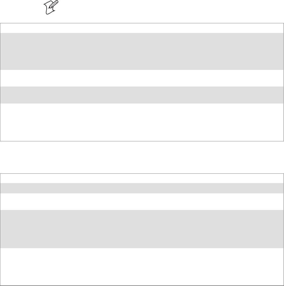
ProgrammingChapter —7
270 700 Series Color Mobile Computer User’s Manual
Set Information Functions
AddWep()
Call this function to add a WEP key to the radio. Call this function multi-
pletimeswhenaddingmorethanoneWEPkey.Savethe“default”keyfor
last. For example, when adding four keys, and the second key is the default
transmit key, add keys 1, 3 and 4 before you add key 2.
Note: Addthedefaulttransmitkeylast.
Syntax UINT AddWep( ULONG, BOOL, TCHAR * );
Parameters ULONG Specifies the key index to be set. Valid values are 0–3.
BOOL When set to TRUE, specifies that this key is the default transmit key.
TCHAR Pointer to a character array that specifies the key data in either HEX (length of
10 or 26) or ASCII (length of 5 or 13). This string must be null-terminated.
Return Values ERROR_SUCCESS when successful, ERR_QUERY_FAILED when the query failed, or
ERR_CONNECT_FAILED if a connection with the radio failed.
Remarks When adding WEP keys to the radio, turn off encryption before you add the keys, then turn en-
cryption back on afterwards. Also, be sure to add the TRANSMIT KEY last.
Definitions #ifdef DYNAMIC_LOADING
typedef UINT (*PFN_AddWep)(ULONG, BOOL, TCHAR *);
#else
UINT AddWep(ULONG, BOOL, TCHAR *);
#endif
EnableWep()
Enables or disables WEP encryption on the radio (TRUE/FALSE).
Syntax UINT EnableWep( BOOL );
Parameters Set BOOL to TRUE to enable WEP encryption, or FALSE to disable WEP encryption.
Return Values ERROR_SUCCESS when successful, ERR_QUERY_FAILED when the query failed, or
ERR_CONNECT_FAILED if a connection with the radio failed.
Remarks Call this function with TRUE as the parameter to enable WEP encryption. Call this function with
the FALSE parameter to disable WEP encryption. This call is an alias for EncryptionStatus(). See
the following:
EnableWEP(TRUE) = EncryptionStatus(NDIS_ENCRYPTION_1_ENABLED)
EnableWEP(FALSE) = EncryptionStatus(NDIS_ENCRYPTION_DISABLED)
Definitions #ifdef DYNAMIC_LOADING
typedef UINT (*PFN_EnableWep)(BOOL);
#else
UINT EnableWep(BOOL);
#endif

Programming—Chapter 7
271700 Series Color Mobile Computer User’s Manual
EncryptionStatus()
Call this function to set the desired encryption status.
Syntax UINT EncryptionStatus( UINT mode );
Parameters NDIS_ENCRYPTION_1_ENABLED WEP is enabled; TKIP and AES are not
enabled, and a transmit key may or may not be
available. (same as
NDIS_RADIO_WEP_ENABLED)
NDIS_ENCRYPTION_DISABLED Indicates that AES, TKIP, and WEP are
disabled, and a transmit key is available. (Same
as NDIS_RADIO_WEP_DISABLED)
NDIS_ENCRYPTION_NOT_SUPPORTED Indicates that encryption (WEP, TKIP, and
AES) is not supported. (Same as
NDIS_RADIO_WEP_NOT_SUPPORTED)
NDIS_ENCRYPTION_1_KEY_ABSENT Indicates that AES, TKIP, and WEP are
disabled, and a transmit key is not available.
(Same as NDIS_RADIO_WEP_ABSENT)
NDIS_ENCRYPTION_2_ENABLED IndicatesthatTKIPandWEPareenabled;AES
is not enabled, and a transmit key is available.
NDIS_ENCRYPTION_2_KEY_ABSENT Indicates that there are no transmit keys
available for use by TKIP or WEP, TKIP and
WEP are enabled; and AES is not enabled.
NDIS_ENCRYPTION_3_ENABLED Indicates that AES, TKIP, and WEP are
enabled, and a transmit key is available.
NDIS_ENCRYPTION_3_KEY_ABSENT Indicates that there are no transmit keys
available for use by AES, TKIP, or WEP, and
AES, TKIP, and WEP are enabled.
Return Values ERROR_SUCCESS when successful, ERR_QUERY_FAILED when the query failed, or
ERR_CONNECT_FAILED if a connection with the radio failed.
Remarks None.
Definitions #ifdef DYNAMIC_LOADING
typedef UINT (*PFN_EncryptionStatus)(UINT mode);
#else
UINT EncryptionStatus(UINT mode);
#endif

ProgrammingChapter —7
272 700 Series Color Mobile Computer User’s Manual
SetAuthenticationMode()
Call this function to set the desired authentication mode.
Syntax UINT SetAuthenticationMode( ULONG );
Parameters NDIS_RADIO_AUTH_MODE_OPEN 802.11 Open Authentication. Indicates that
the radio is using an open system.
NDIS_RADIO_AUTH_MODE_SHARED 802.11 Shared Authentication. Indicates that
the radio is using a shared key.
NDIS_RADIO_AUTH_MODE_AUTO Auto switch between Open/Shared. Indicates
automatic detection is used when available.
NDIS_RADIO_AUTH_MODE_ERROR Defined as error value. Indicates the authenti-
cation mode was not determined at this time
or is unknown.
NDIS_RADIO_AUTH_MODE_WPA WPA Authentication
NDIS_RADIO_AUTH_MODE_WPA_PSK WPA Preshared Key Authentication
NDIS_RADIO_AUTH_MODE_WPA_NONE WPA None
Return Values ERROR_SUCCESS when successful, ERR_QUERY_FAILED when the query failed, or
ERR_CONNECT_FAILED if a connection with the radio failed.
Remarks None.
Definitions #ifdef DYNAMIC_LOADING
typedef UINT (*PFN_SetAuthenticationMode)(ULONG);
#else
UINT SetAuthenticationMode(ULONG);
#endif
SetChannel()
This function is currently not implemented. Ad-hoc networks automatical-
ly select a channel or use the already existing channel.
Syntax UINT SetChannel( USHORT );
Parameters USHORT value that should populate with the desired channel (1–14).
Return Values None.
Remarks None.
Definitions #ifdef DYNAMIC_LOADING
typedef UINT (*PFN_SetChannel)(USHORT);
#else
UINT SetChannel(USHORT);
#endif

Programming—Chapter 7
273700 Series Color Mobile Computer User’s Manual
SetNetworkMode()
Call this function to set the desired Network Mode.
Syntax UINT SetNetworkMode( ULONG );
Parameters NDIS_NET_MODE_IBSS 802.11 Ad-Hoc Mode.
NDIS_NET_MODE_ESS 802.11 Infrastructure Mode.
NDIS_NET_MODE_UNKNOWN Anything Else/Unknown Error
NDIS_NET_AUTO_UNKNOWN Automatic Selection. Use of this option is not supported or
recommended.
NDIS_NET_TYPE_OFDM_5G 5Gigahertz54Mbps
NDIS_NET_TYPE_OFDM_2_4G 802.11 2.4 Gigahertz
Return Values ERROR_SUCCESS when successful, ERR_QUERY_FAILED when the query failed, or
ERR_CONNECT_FAILED if a connection with the radio failed.
Remarks None.
Definitions #ifdef DYNAMIC_LOADING
typedef UINT (*PFN_SetNetworkMode)(ULONG);
#else
UINT SetNetworkMode(ULONG);
#endif
SetPowerMode()
Call this function to set the desired power mode.
Syntax UINT SetPowerMode( ULONG mode );
Parameters NDIS_RADIO_POWER_MODE_CAM Continuous Access Mode (ie: always on).
NDIS_RADIO_POWER_MODE_PSP Power Saving Mode.
NDIS_RADIO_POWER_UNKNOWN Unknown power mode.
NDIS_RADIO_POWER_AUTO Auto. (Available for 730 Computers)
NDIS_RADIO_POWER_MODE_FAST_PSP Fast PSP, good savings, fast
Return Values ERROR_SUCCESS when successful, ERR_QUERY_FAILED when the query failed, or
ERR_CONNECT_FAILED if a connection with the radio failed.
Remarks None.
Definitions #ifdef DYNAMIC_LOADING
typedef UINT (*PFN_SetPowerMode)(ULONG mode);
#else
UINT SetPowerMode(ULONG mode);
#endif

ProgrammingChapter —7
274 700 Series Color Mobile Computer User’s Manual
SetSSID()
Call this function with a pointer to a null-terminated TCHAR array con-
taining the desired SSID to set the desired SSID of the adapter.
Syntax UINT SetSSID( TCHAR * );
Parameters Pointer to a character array that contains the desired SSID. This should be null-terminated.
Return Values ERROR_SUCCESS when successful, ERR_QUERY_FAILED when the query failed, or
ERR_CONNECT_FAILED if a connection with the radio failed.
Remarks If an “ANY” network is desired, pass in _T(“ANY”).
Definitions #ifdef DYNAMIC_LOADING
typedef UINT (*PFN_SetSSID)(TCHAR *);
#else
UINT SetSSID(TCHAR *);
#endif
SetCCXStatus()
Call this function to set the desired CCX / Network EAP status.
Syntax UINT SetCCXStatus( ULONG );
Parameters NDIS_NETWORK_EAP_MODE_OFF Disable Network EAP / CCX
NDIS_NETWORK_EAP_MODE_ON Enable Network EAP / CCX
Return Values ERROR_SUCCESS when successful, ERR_QUERY_FAILED when the query failed, or
ERR_CONNECT_FAILED if a connection with the radio failed.
Remarks None.
Definitions #ifdef DYNAMIC_LOADING
typedef UINT (*PFN_SetCCXStatus)(ULONG);
#else
UINT SetCCXStatus(ULONG);
#endif
SetMixedCellMode()
Call this function to set the desired mixed cell mode.
Syntax UINT SetMixedCellMode( ULONG );
Parameters NDIS_MIXED_CELL_OFF Disable Mixed Cell
NDIS_MIXED_CELL_ON Enable Mixed Cell
Return Values ERROR_SUCCESS when successful, ERR_QUERY_FAILED when the query failed, or
ERR_CONNECT_FAILED if a connection with the radio failed.
Remarks None.
Definitions #ifdef DYNAMIC_LOADING
typedef UINT (*PFN_SetMixedCellMode)(ULONG);
#else
UINT SetMixedCellMode(ULONG);
#endif

Programming—Chapter 7
275700 Series Color Mobile Computer User’s Manual
RemoveWep()
Call this function with a key index of 0–3 to remove the WEP key at that
index.
Syntax UINT RemoveWep( ULONG );
Parameters ULONG value that specifies the key index to set. Valid values are 0–3.
Return Values ERROR_SUCCESS when successful, ERR_QUERY_FAILED when the query failed, or
ERR_CONNECT_FAILED if a connection with the radio failed.
Remarks On disassociation with all BSSIDs of the current service set, WEP key is removed by the adapter.
Definitions #ifdef DYNAMIC_LOADING
typedef UINT (*PFN_RemoveWEP)(ULONG);
#else
UINT RemoveWEP(ULONG);
#endif
Helper Functions
ConfigureProfile()
If using the Intermec 802.11 Profile Management system, you can pro-
gram the API to configure the radio to a specific profile by passing the
profile name.
Syntax UINT ConfigureProfile( TCHAR * );
Parameters Pointer to a character array that contains the profile name. This should be null-terminated.
Return Values ERROR_SUCCESS when successful, ERR_QUERY_FAILED when the query failed, or
ERR_CONNECT_FAILED if a connection with the radio failed.
Remarks Call this function with a pointer to a null-terminated TCHAR array that contains the name of the
profile you wish to configure. This function reads profile data from the profile manager, sets that
profile as the default active profile, and configures the radio appropriately.
If needed, the supplicant and any other related services are automatically started and stopped.
Definitions #ifdef DYNAMIC_LOADING
typedef UINT (*PFN_ConfigureProfile)(TCHAR *);
#else
UINT ConfigureProfile(TCHAR *);
#endif

ProgrammingChapter —7
276 700 Series Color Mobile Computer User’s Manual
EnableZeroConfig()
This enables or disables the Wireless Zero Configuration Wizard from
Microsoft. After calling this function, a warm-boot is required for the
change to take effect.
Note: Enabling this function effectively disables all the SET commands in
this API.
Syntax UINT EnableZeroConfig( USHORT );
Parameters TRUE Enable Wireless Zero Config
FALSE Disable Wireless Zero Config
Return Values ERROR_SUCCESS when successful, ERR_ZERO_CONFIG_CHANGE_FAILED when the
query failed.
Remarks Call this function to set the desired Zero Config status.
Definitions #ifdef DYNAMIC_LOADING
typedef UINT (*PFN_EnableZeroConfig)(USHORT);
#else
UINT EnableZeroConfig(USHORT);
#endif
isZeroConfigEnabled()
Call this function to determine whether Zero Config is currently enabled.
Syntax UINT isZeroConfigEnabled( );
Parameters None.
Return Values TRUE if ZeroConfig is enabled, and FALSE if it is disabled.
Remarks None.
Definitions #ifdef DYNAMIC_LOADING
typedef UINT (*PFN_isZeroConfigEnabled)();
#else
UINT isZeroConfigEnabled();
#endif
isOrinoco()
Call this function to determine whether the current radio is an
ORiNOCO, Lucent, or WaveLAN radio.
Syntax UINT isOrinoco( );
Parameters None.
Return Values TRUE if this is an ORiNOCO radio, and FALSE if it is not.
Remarks None.
Definitions #ifdef DYNAMIC_LOADING
typedef UINT (*PFN_isOrinoco)();
#else
UINT isOrinoco();
#endif

Programming—Chapter 7
277700 Series Color Mobile Computer User’s Manual
isSupplicantRunning()
Call this function to determine whether the security supplicant is running.
Syntax UINT isSupplicantRunning( );
Parameters None.
Return Values TRUE if the security supplicant is running, FALSE if it is not running.
Remarks None.
Definitions #ifdef DYNAMIC_LOADING
typedef UINT (*PFN_isSupplicantRunning)();
#else
UINT isSupplicantRunning();
#endif
StartScanList()
If a scan list is configured on the system, this causes the API to begin the
process of scanning for an available network. This call can take quite a
while to process (depending upon the length of the scan list and how long it
takestofindavalidnetwork), you may wish to call it from a separate
thread.
Syntax UINT StartScanList( );
Parameters None.
Return Values ERROR_SUCCESS when successful.
Remarks Call this function to start the scan list functionality of the system.
Definitions #ifdef DYNAMIC_LOADING
typedef UINT (*PFN_StartScanList)();
#else
UINT StartScanList();
#endif
StartSupplicant()
Call this function to start the supplicant service if it is installed on the sys-
tem.
Syntax UINT StartSupplicant( );
Parameters None.
Return Values ERROR_SUCCESS when successful.
Remarks None.
Definitions #ifdef DYNAMIC_LOADING
typedef UINT (*PFN_StartSupplicant)();
#else
UINT StartSupplicant();
#endif

ProgrammingChapter —7
278 700 Series Color Mobile Computer User’s Manual
StopSupplicant()
Call this function to stop the supplicant service.
Syntax UINT StopSupplicant( );
Parameters None.
Return Values ERROR_SUCCESS when successful.
Remarks None.
Definitions #ifdef DYNAMIC_LOADING
typedef UINT (*PFN_StopSupplicant)();
#else
UINT StopSupplicant();
#endif
isDHCPEnabled()
Call this function to determine whether DHCP is enabled on the current
adapter.
Syntax UINT isDHCPEnabled( );
Parameters None.
Return Values TRUE if DHCP is enabled, FALSE if it is not.
Remarks None.
Definitions #ifdef DYNAMIC_LOADING
typedef UINT (*PFN_isDHCPEnabled)();
#else
UINT isDHCPEnabled();
#endif
RenewDHCP()
Call this function to force a DHCP renewal on the current network adap-
ter.
Syntax UINT RenewDHCP( );
Parameters None.
Return Values ERROR_SUCCESS when successful.
Remarks You should not have to call this function on Microsoft PocketPC 2003 or Microsoft Windows CE
4.2 .NET and later devices.
Definitions #ifdef DYNAMIC_LOADING
typedef UINT (*PFN_RenewDHCP)();
#else
UINT RenewDHCP();
#endif

Programming—Chapter 7
279700 Series Color Mobile Computer User’s Manual
GetCurrentDriverName()
Call this function to populate the TCHAR array with the driver name.
Syntax UINT GetCurrentDriverName( TCHAR *);
Parameters Pointer to a TCHAR array which contains the name of the driver when successful.
Return Values ERROR_SUCCESS when successful.
Remarks This function is called with a pointer to a TCHAR array that is large enough to hold the name of
the driver PLUS the null terminator.
Definitions #ifdef DYNAMIC_LOADING
typedef UINT (*PFN_GetCurrentDriverName)(TCHAR *);
#else
UINT GetCurrentDriverName(TCHAR *);
#endif
ResetRadioToSystemSave()
Call this function to force the radio to reset to the last desired active pro-
file.
Syntax UINT ResetRadioToSystemSave( );
Parameters None.
Return Values ERROR_SUCCESS when successful.
Remarks None.
Definitions #ifdef DYNAMIC_LOADING
typedef UINT (*PFN_ResetRadioToSystemSave)();
#else
UINT ResetRadioToSystemSave();
#endif
EnableSuppLogging()
Call this function to set the desired supplicant logging mode.
Syntax UINT EnableSuppLogging( ULONG );
Parameters NDIS_SUPP_LOGGING_ON Supplicant Logging Enabled
NDIS_SUPP_LOGGING_OFF Supplicant Logging Disabled
Return Values ERROR_SUCCESS when successful.
Remarks None.
Definitions #ifdef DYNAMIC_LOADING
typedef UINT (*PFN_EnableSuppLogging)(ULONG);
#else
UINT EnableSuppLogging(ULONG);
#endif

ProgrammingChapter —7
280 700 Series Color Mobile Computer User’s Manual
SwitchPacketDriver()
Call this function to switch between available packet drivers on the system.
Syntax UINT SwitchPacketDriver( USHORT );
Parameters INTERMEC_PACKET_DRIVER Intermec Packet Driver (ZNICZIO)
NDISUIO_PACKET_DRIVER Microsoft Packet Driver (NDISUIO)
Return Values ERROR_SUCCESS when successful.
Remarks After switching to a new packet driver, perform a warm boot for changes to take effect.
Definitions #ifdef DYNAMIC_LOADING
typedef UINT (*PFN_SwitchPacketDriver)(USHORT);
#else
UINT SwitchPacketDriver(USHORT);
#endif
Deprecated Functions
The following functions are deprecated. While these are not removed from
the API, these are no longer supported. Their parameters are no longer
applicable and the return value for all of these functions is:
ERR_FUNCTION_DEPRECATED
Function Syntax
GetRTSThreshold(Deprecated) UINT GetRTSThreshold( USHORT &);
GetMedia(Deprecated) UINT GetMedia( ULONG &);
GetMedium(Deprecated) UINT GetMedium( ULONG &);
GetNicStats(Deprecated) UINT GetNicStats( NDIS_802_11_STATISTICS &);
SetRTSThreshold(Deprecated) UINT SetRTSThreshold( USHORT &);
SetTXRate(Deprecated) UINT SetTXRate( UCHAR );
EncryptWepKeyForRegistry(Deprecated) UINT EncryptWepKeyForRegistry( TCHAR * szDest,
TCHAR * szSource );
SetDiversity(Deprecicated) UINT SetDiversity( USHORT );
Programming—Chapter 7
281700 Series Color Mobile Computer User’s Manual
Notifications
Use the following information to programmatically control the vibrator, to
write an application to turn on the vibrator when a message is received via
the WLAN radio link, and turn it off when the user hits a key.
Vibrator support is implemented in the NLED driver as a false LED. The
vibrator is LED 5 and is identified with an CycleAdjust of –1. The vibrate
option is only available in the notifications panel when the vibrator is pres-
ent in the system.
Regarding an applications interface to NLED.DLL, LEDs must be avail-
able for use by applications. This is possible via two functions exported by
the COREDLL.DLL file. To use the LED functions, declare these as ex-
tern ”C” as follows:
extern ”C” BOOL WINAPI NLEDGetDeviceInfo(UINT nInfoId,
void *pOutput);
extern ”C” BOOL WINAPI NLEDSetDevice( UINT nDeviceId, void
*pInput);
The LEDs are enumerated for access through the data structures associated
with these APIs:
SNotification LED 0
SRadio On LED 1 (does not apply to the 730 Computer)
SAlpha Lock LED 2
SScanner LED 3
SLow Battery 4
SVibrator 5 (does not apply to the 730 Computer)

ProgrammingChapter —7
282 700 Series Color Mobile Computer User’s Manual
NLEDGetDeviceInfo
Usage
#include “nled.h”
Syntax
BOOL NLEDGetDeviceInfo ( UINT nInfoId, void *pOutput );
Parameters
nInfoId Integer specifying the information to return. These values are defined:
NLED_COUNT_INFO Indicates the pOutput buffer specifies the number of LEDs on
the device.
NLED_SUPPORTS_INFO_ID Indicates the pOutput buffer specifies information about the
capabilities supported by the LED.
NLED_SETTINGS_INFO_ID Indicates the pOutput buffer contains information about the
LED current settings.
pOutput Pointer to the buffer to which the information is returned. The buffer points to various structure
types defined in “nled.h”, depending on the value of nId, as detailed in the following table:
Value of nID Structure in pOutput
LED_COUNT_INFO NLED_COUNT_INFO
NLED_SUPPORTS_INFO NLED_SUPPORTS_INFO
NLED_SETTINGS_INFO NLED_SETTINGS_INFO
NLEDSetDevice
Usage
#include “nled.h”
Syntax
BOOL NLEDSetDevice ( UINT nDeviceId, void *pInput );
Parameters
nDeviceId Integer specifying the device identification. The following is defined:
NLED_SETTINGS_INFO_ID Contains information about the desired LED settings.
pInput Pointer to the buffer that contains the NLED_SETTINGS_INFO structure.
Programming—Chapter 7
283700 Series Color Mobile Computer User’s Manual
Reboot Functions
There are several methods, via Kernel I/O Control functions, that an ap-
plication program can use to force the 700 Color Computer to reboot.
IOCTL_HAL_REBOOT
IOCTL_HAL_REBOOT performs a warm-boot. See page 255.
IOCTL_HAL_COLDBOOT
Invoking the KernelIOControl function with
IOCTL_HAL_COLDBOOT forces a cold reboot. This resets the 700
Color Computer and reloads Windows CE as if a power-up was
performed. The contents of the Windows CE RAM-based object store are
discarded. See page 252.
IOCTL_HAL_WARMBOOT
This function is supported on 700 Color Computers. It performs a warm
boot of the system, preserving the object store. See page 252.

ProgrammingChapter —7
284 700 Series Color Mobile Computer User’s Manual
Remapping the Keypad
Note: Use caution when remapping the keypad. Improper remapping may
render the keypad unusable. Data within the 700 Color Computer could
also be lost, should any problems occur.
Applications have the ability to remap keys on the 700 Color Numeric
Keypad and 700 Color Alphanumeric Keypad. This will allow applications
to enable keys that would otherwise not be available, such as the [F1]
function key. Also, to disable keys that should not be available, such as the
alpha key because no alpha entry is required. Care should be exercised
when attempting to remap the keypad because improper remapping may
cause the keypad to become unusable. This can be corrected by cold boot-
ing the device which will cause the default keymap to be loaded again.
Note that remapping the keys in this way affects the key mapping for the
entire system, not just for the application that does the remapping.
There are three “planes” supported for the 700 Color Numeric Keypad
and Alphanumeric Keypad. Keys that are to be used in more than one shift
plane must be described in each plane.
Unshifted Plane
The unshifted plane contains values from the keypad when not pressed
with other keys, such as the following:
Press the Keys
Numeric Keypad Alphanumeric Keypad To Enter This
1M
1
5T
5
9Y
9
Gold Plane
The gold plane contains values from the keypad when a key is simulta-
neously pressed with the [Gold] bkey on the numeric keypad or the
[Gold/White]
c
key on the alphanumeric keypad, such as the following:
Press the Keys
Numeric Keypad Alphanumeric Keypad To Enter This
[Gold] b
1
[Gold/White]
ce
Send
[Gold] b
5
[Gold/White]
cC
A3
[Gold] b
9
[Gold/White]
cP
PgDn

Programming—Chapter 7
285700 Series Color Mobile Computer User’s Manual
Alpha (Blue) Plane
The alpha plane contains values from the keypad when the keypad has
beenplacedinalphamodebypressingthebluealphakey,suchasthefol-
lowing:
Press the Keys
Numeric Keypad Alphanumeric Keypad To Enter This
[Alpha] F
1
[Alpha]
dg
Caps
[Alpha] F
5
[Alpha]
dJ
j
[Alpha] F
9
[Alpha]
dW
w
Key Values
Key values for each plane are stored in the registry. All units ship with a
default key mapping already loaded in the registry. Applications that wish
to change the default mapping need to read the appropriate key from the
registry into an array of Words, modify the values required and then write
the updated values back into the registry. The registry access can be done
with standard Microsoft API calls, such as RegOpenKeyEx(),
RegQueryValueEx(), and RegSetValueEx().
Numeric Keypad
For the 700 Color Numeric Keypad, the following registry keys contain
the plane mappings:
STheunshiftedplanemappingcanbefoundintheregistryat:
HKEY_LOCAL_MACHINE\HARDWARE\DEVICEMAP\KEYBD\Vkey
SThe gold plane mapping can be found in the registry at:
HKEY_LOCAL_MACHINE\HARDWARE\DEVICEMAP\KEYBD\VkeyGold
SThealphaplanemappingcanbefoundintheregistryat:
HKEY_LOCAL_MACHINE\HARDWARE\DEVICEMAP\KEYBD\VkeyAlpha
Alphanumeric Keypad
For the 700 Color Alphanumeric Keypad, the following registry keys con-
tain the plane mappings:
STheunshiftedplanemappingcanbefoundintheregistryat:
HKEY_LOCAL_MACHINE\HARDWARE\DEVICEMAP\KEYBD\ALPHA\Vkey
SThe gold plane mapping can be found in the registry at:
HKEY_LOCAL_MACHINE\HARDWARE\DEVICEMAP\KEYBD\ALPHA\VkeyGold
SThealphaplanemappingcanbefoundintheregistryat:
HKEY_LOCAL_MACHINE\HARDWARE\DEVICEMAP\KEYBD\ALPHA\VkeyAlpha

ProgrammingChapter —7
286 700 Series Color Mobile Computer User’s Manual
How Key Values Are Stored in Registry
To know which fields to update in the registry, you must know what Scan
Codes are assigned to each physical key (see the “Keypad Scan Codes and
Meanings” tableonthenextpage).TheScanCodeisusedatthelowest
level of the system to let the keypad driver know which physical key has
been pressed. The keypad driver takes that scan code and looks it up in a
table (a copy of the one stored in the registry) to determine which values
to pass on to the operating system.
Each registry key is just an array that describes to the keypad driver what
value needs to be passed for each physical key. The key values are indexed
by the scan code, this is a zero-based index. For example in the unshifted
plane, the [4] key has a scan code of 0x06. This means that the seventh
word under the “Vkey” registry key will have the value for the [4] key.
Taking a sample of the “Vkey” registry key shows the following values:
00,00,0B,05,02,03,C1,07,04,03,BE,00,34,00,00,00,. . .
Thevalueis34,00.Thevaluesareinreversebyteorderbecausethatisthe
way the processor handles data. When writing an application, nothing
needs to be done to swap the bytes, as this will happen automatically when
the data is read into a byte value. This is something you just need to be
aware of when looking at the registry. Knowing this, we can see that the
value that the keypad driver will pass to the system is a hex 34. Looking
that up on an UNICODE character chart, we see that it maps to a “4”. If
you wanted the key, labeled “4”, to output the letter “A” instead, you
would need to change the seventh word to “41” (the hexadecimal repre-
sentation of “A” from the UNICODE chart), then put the key back into
the registry.
Note: Do not remap scan codes 0x01, 0x41, 0x42, 0x43, 0x44. Remap-
pingthesescancodescouldrenderyour700ColorComputerunusable
until a cold-boot is performed.
If you wish to disable a certain key, remap its scan code to 0x00.
Change Notification
Just changing the registry keys will not immediately change the key
mappings. To notify the keypad driver that the registry has been updated,
signal the “ITC_KEYBOARD_CHANGE” named event using the
CreateEvent() API.
Advanced Keypad Remapping
It is also possible to map multiple key presses to one button and to map
named system events to a button. The multiple key press option could be
useful to cut down on the number of keys needed to press in a given situa-
tion or to remap which key behaves like the action key. Mapping events to
a button could be useful to change which buttons will fire the scanner,
control volume, and allow for suspending and resuming the device. If you
need help performing one of these advanced topics please contact Intermec
Technical Support.

Programming—Chapter 7
287700 Series Color Mobile Computer User’s Manual
Scan Codes
At the lowest driver level, the 700 Color Numeric Keypad and the 700
ColorAlphanumericKeypadidentifieskeysasscancodes.Thesescan
codes are sent via the keypad microcontroller, and cannot be changed
without modifying the keypad firmware.
Numeric Keypad
The following scan codes pertain to the 700 Color Numeric keypad:
Numeric Keypad Scan Codes and Meanings
PressthisKey Meaning ScanCode
Reserved 0x00
I
I/O button 0x01
Scanner Handle Trigger 0x02
Scanner Left 0x03
Scanner Right 0x04
4
4/GHI/A2 0x06
None 0x07
L
Left arrow/Back Tab 0x08
None 0x09
K
BkSp// (forward slash) 0x0A
b
[Gold] key 0x0B
None 0x0C
E
Esc/– (minus sign) 0x0D
D
Down arrow/Volume decrease 0x0E
1
1/Caps/Send 0x0F
7
7/PQRS/PgUp 0x10
F
[Alpha] key 0x11
None 0x12
U
Up arrow/Volume increase 0x13
R
Right arrow/Tab 0x14
2
2/ABC/End 0x15
8
8/TUV/* (asterisk) 0x16
0
0/Win 0x17
5
5/JKL/A3 0x18
None 0x19
A
Action/+ (plus symbol) 0x1A
3
3/DEF/backlight 0x1B
9
9/WXYZ/PgDn 0x1C

ProgrammingChapter —7
288 700 Series Color Mobile Computer User’s Manual
Numeric Keypad Scan Codes and Meanings (continued)
ScanCodeMeaningPressthisKey
e
Enter/@ (at symbol) 0x1D
6
6/MNO/A4 0x1E
None 0x1F–0x40
B
Charge Detect 0x41
C
LCD frontlight 0x42
b
Ambient light 0x42
Threshold crossed 0x42
Headset detected 0x43
Keypad Backlight 0x44
b
Ambient Light 0x44
Threshold Crossed 0x44
Alphanumeric Keypad
The following scan codes pertain to the 700 Color Alphanumeric keypad:
Alphanumeric Keypad Scan Codes and Meanings
PressthisKey Meaning ScanCode
Reserved 0x00
i
I/O button 0x01
Scanner Handle Trigger 0x02
Scanner Left 0x03
Scanner Right 0x04
A
A/A1 key 0x05
B
B/A2 key 0x06
e
Escape/Send 0x07
j
Left arrow/Back Tab 0x08
k
Up arrow/Volume increase 0x09
m
Down arrow/Volume decrease 0x0A
l
Right arrow/Tab 0x0B
a
Action/End 0x0C
E
E/Win 0x0D
F
F/= (equal sign) 0x0E
G
G/* (asterisk) 0x0F
C
C/A3 0x10
H
H// (forward slash) 0x11
D
D/A4 0x12

Programming—Chapter 7
289700 Series Color Mobile Computer User’s Manual
Alphanumeric Keypad Scan Codes and Meanings (continued)
ScanCodeMeaningPressthisKey
J
J/PgUp 0x13
K
K/@ (as symbol) 0x14
L
L/– (minus sign) 0x15
M
M/1 0x16
N
N/2 0x17
I
I/backlight 0x18
P
P/PgDn 0x19
Q
Q/, (comma) 0x1A
R
R/+ (plus sign) 0x1B
S
S/4 0x1C
T
T/5 0x1D
O
O/3 0x1E
g
Caps/Lock 0x1F
h
BkSp 0x20
V
V/. (period) 0x21
W
W/7 0x22
X
X/8 0x23
U
U/6 0x24
c
Gold/White 0x25
NumLock 0x26
b
Space 0x27
Z
Z/0 0x28
f
Enter 0x29
Y
Y/9 0x2A
None 0x2B–0x40
B
Charge Detect 0x41
C
LCD frontlight 0x42
b
Ambient light 0x42
Threshold crossed 0x42
Headset detected 0x43
Keypad Backlight 0x44
b
Ambient Light 0x44
Threshold Crossed 0x44
ProgrammingChapter —7
290 700 Series Color Mobile Computer User’s Manual
Sample View of Registry Keys
The following is a sample view of the current default key mapping for the
700 Color Numeric Keypad. See the registry on your device for the latest
key mappings.
[HKEY_LOCAL_MACHINE\HARDWARE\DEVICEMAP\KEYBD]
”ResumeMask”=dword:7
”Vkey”=hex: 00,00,0B,05,02,03,C1,07,04,03,BE,00,34,00,00,00,\
25,00,00,00,08,00,03,02,00,00,1B,00,28,00,31,00,\
37,00,01,02,00,00,26,00,27,00,32,00,38,00,30,00,\
35,00,00,00,01,03,33,00,39,00,0D,00,36,00,00,00,\
00,00,00,00,00,00,00,00,00,00,00,00,00,00,00,00,\
00,00,00,00,00,00,00,00,00,00,00,00,00,00,00,00,\
00,00,00,00,00,00,00,00,00,00,00,00,00,00,00,00,\
00,00,00,00,00,00,00,00,00,00,00,00,00,00,00,00,\
00,00,07,05,01,05,03,05,02,05
”VkeyGold”=hex: 00,00,0B,05,02,03,C1,07,04,03,BE,00,34,00,00,00,\
09,01,00,00,BF,00,03,02,00,00,BD,00,75,00,72,00,\
21,00,01,02,00,00,76,00,09,00,73,00,38,01,5B,00,\
35,00,00,00,BB,01,09,05,22,00,32,01,36,00,00,00,\
00,00,00,00,00,00,00,00,00,00,00,00,00,00,00,00,\
00,00,00,00,00,00,00,00,00,00,00,00,00,00,00,00,\
00,00,00,00,00,00,00,00,00,00,00,00,00,00,00,00,\
00,00,00,00,00,00,00,00,00,00,00,00,00,00,00,00,\
00,00,07,05,01,05,03,05,02,05
”VkeyAlpha”=hex: 00,00,0B,05,02,03,C1,07,04,03,BE,00,47,00,00,00,\
25,00,00,00,08,00,03,02,00,00,1B,00,28,00,02,02,\
50,00,01,02,00,00,26,00,27,00,41,00,54,00,20,00,\
4A,00,00,00,01,03,44,00,57,00,0D,00,4D,00,00,00,\
00,00,00,00,00,00,00,00,00,00,00,00,00,00,00,00,\
00,00,00,00,00,00,00,00,00,00,00,00,00,00,00,00,\
00,00,00,00,00,00,00,00,00,00,00,00,00,00,00,00,\
00,00,00,00,00,00,00,00,00,00,00,00,00,00,00,00,\
00,00,07,05,01,05,03,05,02,05

291700 Series Color Mobile Computer User’s Manual
Configurable Settings
A
This appendix contains information about the Data Collection, Intermec
Settings, SNMP, Unit Information, Utilities, and Wireless Network con-
trol panel applets that may be on the 700 Series Color Mobile Computer.
Note: “700 Color” pertains to 740, 741, 750, 751, 760, and 761 Com-
puters unless otherwise noted.
SNMP, Intermec Settings, and Data Collection settings that can appear
under Settings are dependent on what hardware configuration is done for
each 700 Color Computer at the time of shipment. These settings current-
lyonlyappearifascanneroranimageroptionispresent.
Likewise, other control panel applets that are specifically related to the
802.11b or 802.11b/g radio module will appear when a 802.11b or
802.11b/g radio module is installed in a 700 Color Computer. Control
panel applets that are specific for Wireless Printing, CDMA/1xRTT, and
GSM/GPRS radio modules will only appear when each respective hard-
ware configuration is done on the 700 Color Computer. See Chapter 4,
“Network Support,” for more information about the radio modules or the wire-
less printing.
Information about using reader commands and configuration bar codes to
configuresomeofyoursettingsisalsointhisappendix.
Note: Information about the settings you can configure with the Intermec
Settings control panel applet is described in the Intermec Computer Com-
mand Reference Manual (P/N: 073529). The online manual is available
from the Intermec web site at www.intermec.com.
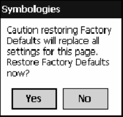
Configurable SettingsAppendix —A
292 700 Series Color Mobile Computer User’s Manual
Configuration Parameters
A configuration parameter changes the way the 700 Color Computer op-
erates, such as configuring a parameter to have the 700 Color Computer
emit a very loud beep in a noisy environment. Use any of the following
methods to execute configuration parameters:
SChange Data Collection and SNMP parameters via control panel ap-
plets later in this appendix.
SSend parameters from an SNMP management station. See “SNMP Con-
figuration on the 700 Color Computer” starting on page 187.
SScan EasySet bar codes. You can use the EasySet bar code creation soft-
ware from Intermec Technologies Corporation to print configuration
labels. Scan the labels to change the scanner configuration and data
transfer settings.
Use the Intermec EasySet software to print configuration labels you can
scan to change your configuration settings. For more information, see
the EasySet online help. EasySet is available from the Intermec Data
Capture web site.
Changing a Parameter Setting
Menus of available parameters for each group are listed. Use the scroll bars
to go through the list. Expand each menu (+) to view its parameter set-
tings. Tap a parameter to select, or expand a parameter (+) to view its sub-
parameters.
Note that each parameter or subparameter is shown with its default setting
or current setting in (< >) brackets. Tap a parameter or subparameter to
select that parameter, then do any of the following to change its setting:
Tap Apply to apply any changes. Note that these illustrations are from a
Symbologies parameter.
STypinganewvalueinanentryfield.
SChoosing a new value from the drop-down list.
SSelecting a different option. The selected option contains a bullet.
STap Defaults,thenApply to restore factory-default settings. Tap Yes
when you are prompted to verify this action.
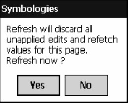
Configurable SettingsAppendix —A
293700 Series Color Mobile Computer User’s Manual
STap Refresh to discard changes and start again. Tap Yes when you are
prompted to verify this action.
About Configuration Parameters
You can find this information about each configuration parameter:
SName and Purpose:
Describes the parameter and its function.
SAction:
Describes what to do with a parameter once that parameter is selected.
SSNMP OID:
Lists the SNMP OID for the parameter.
SSyntax or Options:
Syntax lists the two-character code for the parameter, if the parameter is
configurable by scanning a bar code or by sending parameters through a
network. Both Syntax and Options list acceptable values for the para-
meter.

Configurable SettingsAppendix —A
294 700 Series Color Mobile Computer User’s Manual
Data Collection Control Panel Applet
Note: This applet is not available in units with PSM Build 3.00 or newer.
To determine your PSM Build version, tap Start >Programs >
File Explorer >thePSMinfo text file.
If your unit has PSM Build 3.00 or newer, then you may have the Intermec
Settings control panel applet in place of the Data Collection applet.
Information about the settings you can configure with the Intermec
Settings applet is described in the Intermec Computer Command Reference
Manual. The online manual is available from the Intermec web site at
www.intermec.com.
See “Scanner Control and Data Transfer”intheIntermec Windows CE/
Pocket PC Software Developer’s Kit (SDK) User’s Manual shipped with the
Software Developer’s Kit (SDK) for information about data collection
functions. Note that icons are shown to the left.
To access the settings from the 700 Color Computer, tap Start >Settings
>theSystem tab > Data Collection to access its control panel applet.
Use the left and right arrows to scroll through the tabs along the bottom of
the control panel applet, then tap a tab to access its menus. These tabs rep-
resent the following groups of settings or parameters:
SSymbologies (starting on page 295)
SSymbology Options (starting on page 316)
SBeeper/LED (starting on page 324)
SImager (starting on page 330)
SVirtual Wedge (starting on page 335)

Configurable SettingsAppendix —A
295700 Series Color Mobile Computer User’s Manual
Symbologies
You can change bar code symbology parameter settings in your 700 Color
Computer via the Data Collection control panel applet. The following
parameters are for bar code symbologies. Additional information about the
more common bar code symbologies are in Appendix B, “Bar Codes.” Note
that these parameters are listed in the order of their appearance within this tab.
Most of these symbologies apply to both the imager and the laser scanner
tools. However, when using an imager, the Macro PDF (page 306),Micro
PDF417 (page 308),Matrix2of5(page 310), Telepen (page 311),and
Code 11 (page 312) symbologies are not supported. Likewise, when using
a laser scanner, the QR Code (page 313), Data Matrix (page 314),and
MaxiCode (page 315) symbologies are not supported.
Note: The 730 Computer uses the EV10 APS linear imager which sup-
ports 1D symbologies.
The following table shows which bar code symbologies are supported by
an imager, a laser scanner, or the EV10 APS Linear Imager
Bar Code Symbology Imager Laser Scanner
EV10 APS
Linear Imager
Code 39 XXX
Interleaved 2 of 5 XXX
Standard 2 of 5 XXX
Matrix 2 of 5 X X
Code 128 XXX
Code 93 XXX
Codabar XXX
MSI X X
Plessey XX
UPC XXX
EAN/EAN 128 XXX
Code 11 X X
PDF417 XXX
Micro PDF417 X X
Telepen XX
Data Matrix X
QR Code X
MaxiCode X
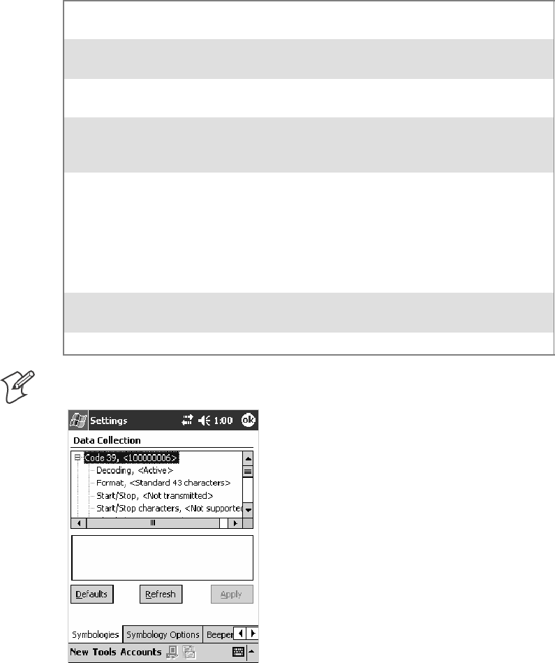
Configurable SettingsAppendix —A
296 700 Series Color Mobile Computer User’s Manual
Code 39
Code 39 is a discrete, self-checking, variable length symbology. The char-
acter set is uppercase A–Z, 0–9, dollar sign ($), period (.), slash (/), per-
cent (%), space ( ), plus (+), and minus (-).
Action
Tap (+) to expand the Code 39 parameter, select the setting to be
changed, then tap an option to change this setting or select an option from
the drop-down list.
SNMP OID
1.3.6.1.4.1.1963.15.3.3.1.1.3.1
Options
Decoding 0
1
Not active
Active (default)
Format 0
1
Standard 43 characters (default)
Full ASCII
Start/Stop 0
1
Not transmitted (default)
Transmitted
Start/Stop characters
(Not supported when us-
ing an imager)
0
1
2
$(dollarsign)only
* (asterisk) only (default)
$ and * (dollar sign and asterisk)
Check digit 0
1
2
3
4
5
6
Not used (default)
Mod 43 transmitted
Mod 43 not transmitted
French CIP transmitted
French CIP not transmitted
Italian CPI transmitted
Italian CPI not transmitted
Bar code length 0
1
Any length (default)
Minimum length
Minimum length 001–254 Minimum length 1–254 (default is 6)
Note:IfBar code length =“1”thenMinimum length is entered.
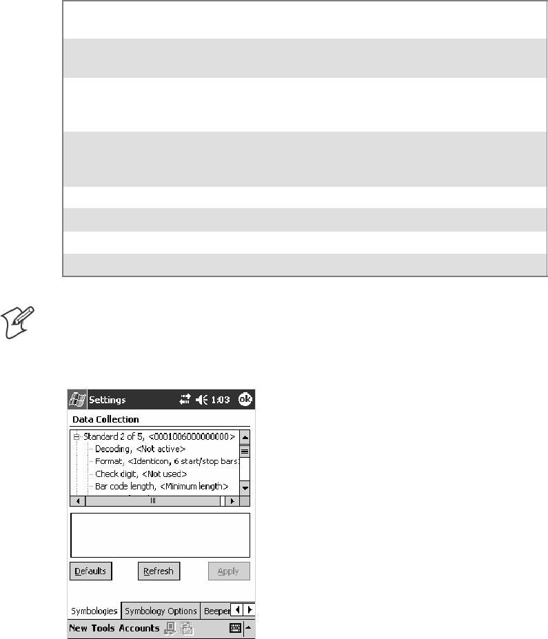
Configurable SettingsAppendix —A
297700 Series Color Mobile Computer User’s Manual
Standard 2 of 5
Standard 2 of 5 is a discrete and self-checking symbology that uses the bars
to encode information and the spaces to separate the individual bars.
Action
Tap (+) to expand the Standard 2 of 5 parameter, select the setting to be
changed, then tap an option to change this setting or select an option from
the drop-down list.
SNMP OID
1.3.6.1.4.1.1963.15.3.3.1.1.4.1
Options
Decoding 0
1
Not active (default)
Active
Format 0
1
Identicon, 6 start/stop bars (default)
Computer Identics, 4 start/stop bars
Check digit 0
1
2
Not used (default)
Mod 10 transmitted
Mod 10 not transmitted
Bar code length 0
1
2
Any length
Minimum length (default)
Fixed lengths
Minimum length 001–254 Minimum length 1–254 (default is 6)
Fixed length 1 000–254 Fixed bar code length 0–254 (default is 0)
Fixed length 2 000–254 Fixed bar code length 0–254 (default is 0)
Fixed length 3 000–254 Fixed bar code length 0–254 (default is 0)
Note:IfBar code length =“1”thenMinimum length is entered. If Bar
code length =“2”thenFixed length 1,Fixed length 2,orFixed length 3
is entered.
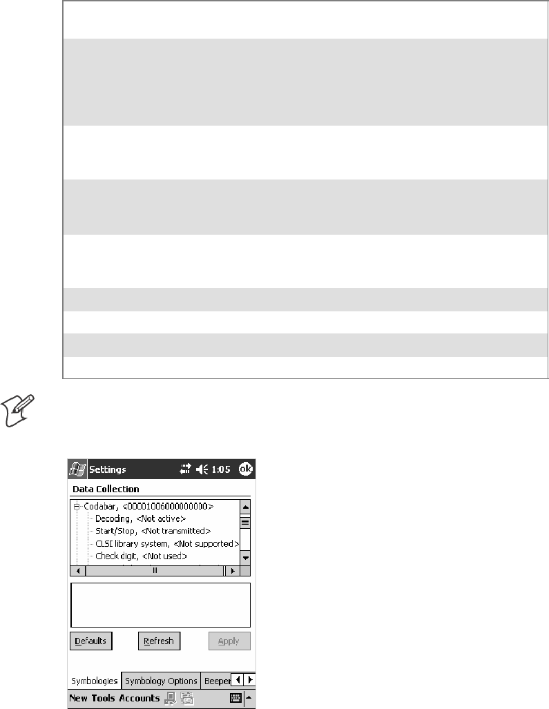
Configurable SettingsAppendix —A
298 700 Series Color Mobile Computer User’s Manual
Codabar
Codabar is a self-checking, discrete symbology.
Action
Tap (+) to expand the Codabar parameter, select a setting to be changed,
then select an option from the drop-down list to change this setting.
SNMP OID
1.3.6.1.4.1.1963.15.3.3.1.1.5.1
Options
Decoding 0
1
Not active (default)
Active
Start/Stop 0
1
2
3
4
Not transmitted (default)
abcd transmitted
ABCD transmitted
abcd/tn*e transmitted
DC1–DC4 transmitted
CLSI library system
(Not supported when us-
ing an imager)
0
1
Not active (default)
Active
Check digit 0
1
2
Not used (default)
Transmitted
Not transmitted
Bar code length 0
1
2
Any length
Minimum length (default)
Fixed lengths
Minimum length 003–254 Minimum length 3–254 (default is 6)
Fixed length 1 000–254 Fixed bar code length 0–254 (default is 0)
Fixed length 2 000–254 Fixed bar code length 0–254 (default is 0)
Fixed length 3 000–254 Fixed bar code length 0–254 (default is 0)
Note:IfBar code length =“1”thenMinimum length is entered. If Bar
code length =“2”thenFixed length 1,Fixed length 2,orFixed length 3
is entered.
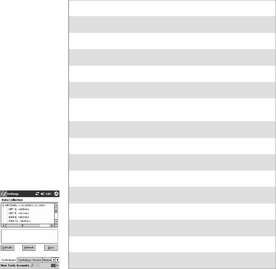
Configurable SettingsAppendix —A
299700 Series Color Mobile Computer User’s Manual
UPC/EAN
UPC/EAN are fixed-length, numeric, continuous symbologies that use
four element widths.
Action
Tap (+) to expand the UPC/EAN parameter, select the setting to be
changed, then select an option to change this setting.
SNMP OID
1.3.6.1.4.1.1963.15.3.3.1.1.6.1
Options
UPC A 0
1
Not Active
Active (default)
UPC E 0
1
Not Active
Active (default)
EAN 8 0
1
Not Active
Active (default)
EAN 13 0
1
Not Active
Active (default)
Add-on digits 0
1
Not required (default)
Required
Add-on 2 digits 0
1
Not active (default)
Active
Add-on 5 digits
(Not supported when us-
ing an imager)
0
1
Not active (default)
Active
UPC A check digit 0
1
Not transmitted
Transmitted (default)
UPC E check digit 0
1
Not transmitted
Transmitted (default)
EAN 8 check digit 0
1
Not transmitted
Transmitted (default)
EAN 13 check digit 0
1
Not transmitted
Transmitted (default)
UPC A number system 0
1
Not transmitted
Transmitted (default)
UPC E number system 0
1
Not transmitted
Transmitted (default)
UPC A re-encoding 0
1
UPC A transmitted as UPC A
UPC A transmitted as EAN 13 (default)
UPC E re-encoding 0
1
UPC E transmitted as UPC E (default)
UPC E transmitted as UPC A
EAN 8 re-encoding 0
1
EAN 8 transmitted as EAN 8 (default)
EAN 8 transmitted as EAN 13
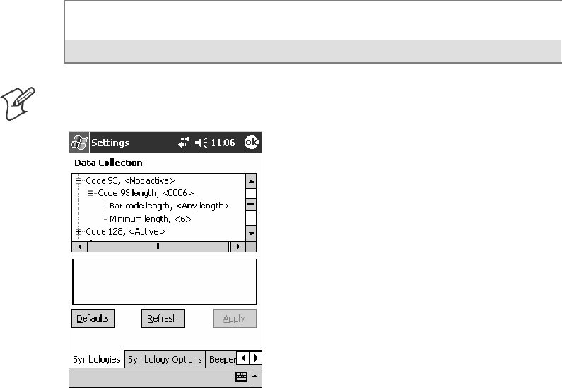
Configurable SettingsAppendix —A
300 700 Series Color Mobile Computer User’s Manual
Code 93
Code 93 is a variable length, continuous symbology that uses four element
widths.
Action
Tap the Code 93 parameter, then select an option to change this parame-
ter setting. Tap (+) to access the Code 93 Lengths parameter.
SNMP OID
1.3.6.1.4.1.1963.15.3.3.1.1.7.1
Options
0 Not active (default)
1Active
Code 93 Length
Sets the Code 93 bar code length.
Action
Tap (+) to expand the Code 93 parameter, then tap (+) to expand the
Code 93 Lengths parameter. Tap the setting to be changed, then tap an
option to change this setting.
SNMP OID
1.3.6.1.4.1.1963.15.3.3.1.1.19.1
Options
Bar code length 0
1
Any length
Minimum length (default)
Minimum length 001–254 Minimum length 1–254 (default is 6)
Note:IfBar code length =“1”thenMinimum length is entered.

Configurable SettingsAppendix —A
301700 Series Color Mobile Computer User’s Manual
Code 128
Code 128 is a variable-length, continuous, high-density, alphanumeric
symbology that uses multiple element widths and supports the extended
ASCII character set.
Action
Tap the Code 128 parameter, then select an option to change this parame-
ter setting.
SNMP OID
1.3.6.1.4.1.1963.15.3.3.1.1.9.1
Options
0 Not active (default)
1Active
This illustration is from a 700 Color Computer using a laser scanner.
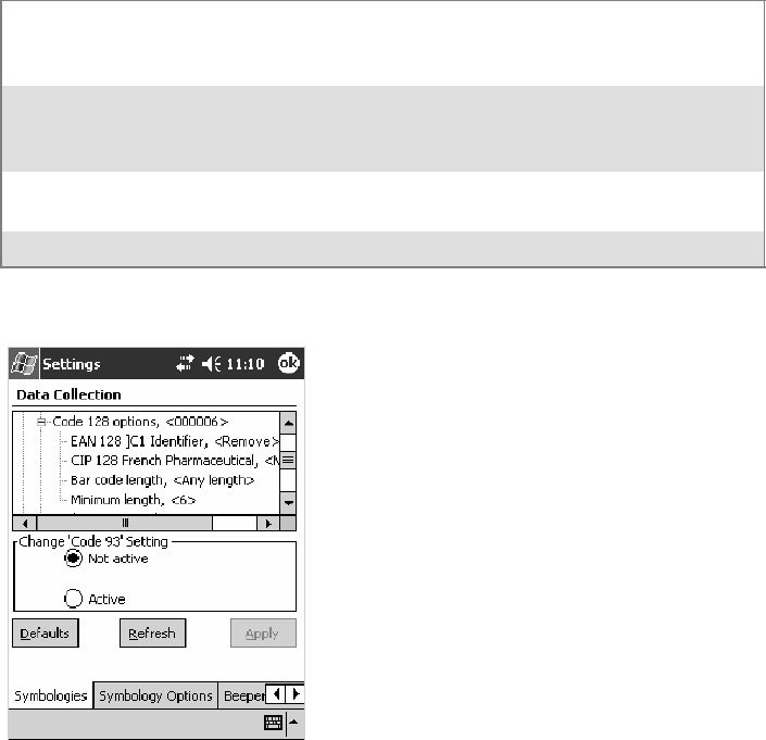
Configurable SettingsAppendix —A
302 700 Series Color Mobile Computer User’s Manual
Code 128 Options
Set the following for the Code 128 parameter. Note that the EAN 128 ]C1
and CIP 128 French Pharmaceutical options are not available when you use
an imager with your 700 Color Computer.
Action
Tap (+) to expand the Code 128 Options parameter, select a setting, then
select an option to change this setting.
SNMP OID
None.
Options
EAN 128 ]C1 Identifier
(Not supported when using an
imager)
0
1
Remove (default)
Include
CIP 128 French Pharmaceutical
(Not supported when using an
imager)
0
1
Not active (default)
Active
Bar code length 0
1
Any length (default)
Minimum length
Minimum length 001–254 Minimum length 1–254 (default is 6)
This illustration is from a 700 Color Computer using a laser scanner.
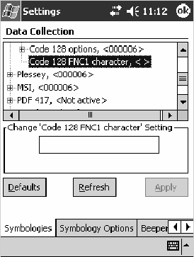
Configurable SettingsAppendix —A
303700 Series Color Mobile Computer User’s Manual
Code 128 FNC1 Character
The Code 128 FNC1 character (EAN 128 norms) can be any ASCII char-
acter and is used as a separator when multiple identifiers and their fields
are concatenated. Note that this is not available when you use an imager with
your 700 Color Computer.
Non-printable ASCII characters can be entered using the following syntax
where HH is the hexadecimal value of the character.
\xHH
For example, the GS character, whose hexadecimal value is 1D, would be
entered as \x1D. In addition,the following characters have their own
identifiers:
SBEL \a
SBS \b
SFF \f
SLF \n
SCR \r
SHT \t
SVT \v
Action
Tap (+) to expand the Code 128 parameter, then type the ASCII charac-
ters to be set for the Code 128 FNC1 character parameter.
SNMP OID
1.3.6.1.4.1.1963.15.3.3.1.1.21.1
Options
Any ASCII character (default is the GS function character — ID hex)
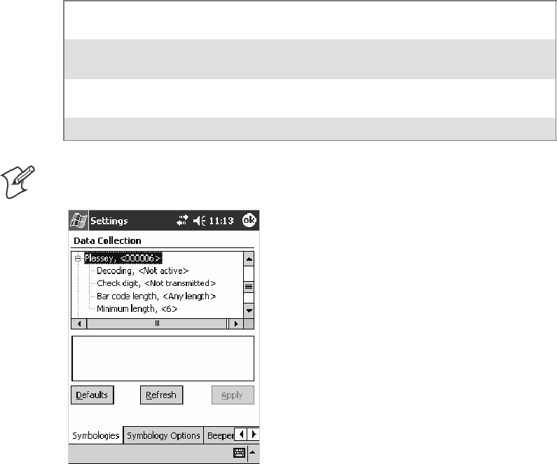
Configurable SettingsAppendix —A
304 700 Series Color Mobile Computer User’s Manual
Plessey
Plessey is a pulse-width modulated symbology like most other bar codes. It
includes a start character, data characters, an eight-bit cyclic check digit,
and a termination bar. The code is continuous and not self-checking. You
need to configure two parameters for Plessey code: Start Code and Check
Digit. Note that this is not available when you use an imager with your 700
Color Computer.
Action
Tap (+) to expand the Plessey parameter, select the setting to be changed,
then select an option to change this setting or select an option from the
drop-down list.
SNMP OID
1.3.6.1.4.1.1963.15.3.3.1.1.10.1
Options
Decoding 0
1
Not active (default)
Active
Check digit 0
1
Not transmitted (default)
Transmitted
Bar code length 0
1
Any length
Minimum length (default)
Minimum length 001–254 Minimum length 1–254 (default is 6)
Note:IfBar code length =“1”thenMinimum length is entered.
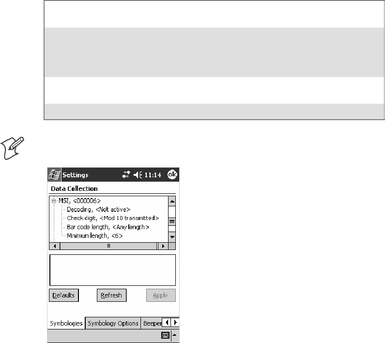
Configurable SettingsAppendix —A
305700 Series Color Mobile Computer User’s Manual
MSI
MSI is a symbology similar to Plessey code (page 304) that includes a start
pattern, data characters, one or two check digits, and a stop pattern. Note
that this is not available when you use an imager with your 700 Color Com-
puter.
Action
Tap (+) to expand the MSI parameter, select the setting to be changed,
then select an option to change this setting or select an option from the
drop-down list.
SNMP OID
1.3.6.1.4.1.1963.15.3.3.1.1.15.1
Options
Decoding 0
1
Not active (default)
Active
Check digit 0
1
2
3
Mod 10 transmitted (default)
Mod 10 not transmitted
Double Mod 10 transmitted
Double Mod 10 not transmitted
Bar code length 0
1
Any length
Minimum length (default)
Minimum length 001–254 Minimum length 1–254 (default is 6)
Note:IfBar code length =“1”thenMinimum length is entered.
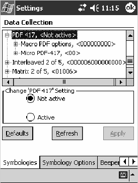
Configurable SettingsAppendix —A
306 700 Series Color Mobile Computer User’s Manual
PDF417
PDF417 is a stacked two-dimensional symbology that provides the ability
to scan across rows of code. Each row consists of start/stop characters, row
identifiers, and symbol characters, which consist of four bars and four
spaces each and contain the actual data. This symbology uses error correc-
tion symbol characters appended at the end to recover loss of data.
Because the virtual wedge translates incoming data into keypad input, the
size of the keypad buffer limits the effective length of the label to 128
characters. Longer labels may be truncated. For PDF417 labels of more
than 128 characters, you can develop an application that bypasses the key-
pad buffer.
Action
Tap the PDF417 parameter, then select an option to change this parame-
ter setting. Tap (+) to access either the Macro PDF options parameter or
the Micro PDF417 parameter.
SNMP OID
1.3.6.1.4.1.1963.15.3.3.1.1.17.1
Options
0Notactive
1Active(default)
This illustration is from a 700 Color Computer using a laser scanner.
Macro PDF options
Macro PDF is used when a long message requires more than one PDF417
label. Note that this is not available when you use an imager with your 700
Color Computer.
SSelect Buffered to store a multi-label PDF417 message in the Sabre
buffer, thus transmitting the entire message when all labels are read.
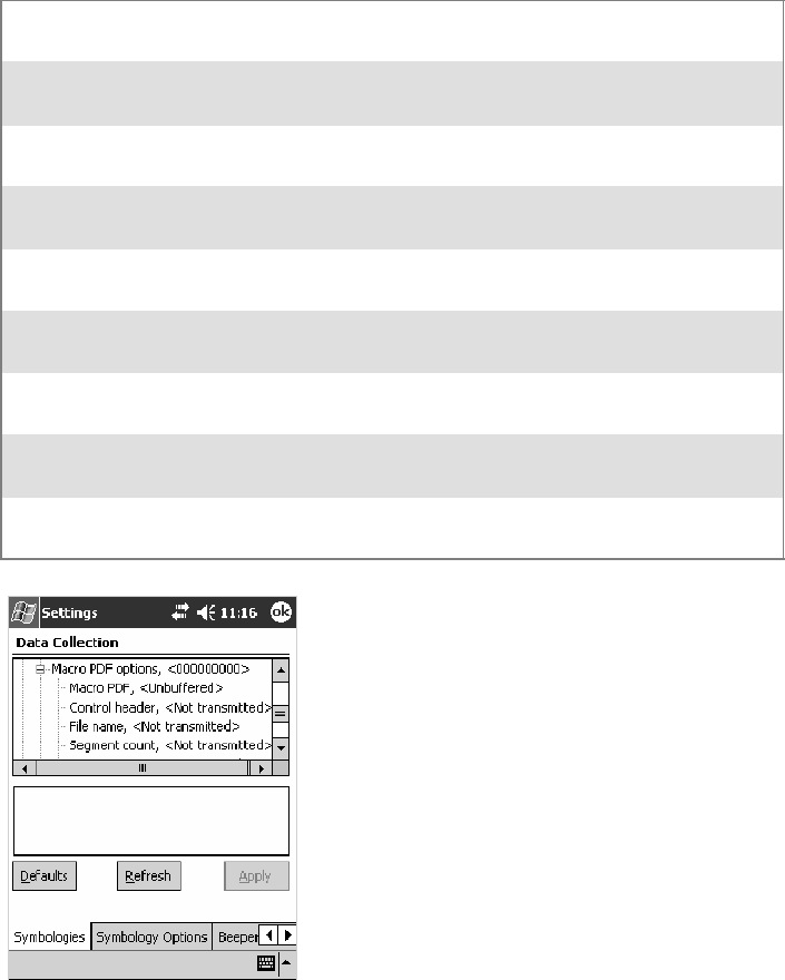
Configurable SettingsAppendix —A
307700 Series Color Mobile Computer User’s Manual
SSelect Unbuffered for multi-label PDF417 messages that are too long
for the Sabre buffer (memory overflow). Each part of the PDF417 label
is transmitted separately, and the host application must then assemble
the message using the macro PDF control header transmitted with each
label. Control Header is only present in macro PDF codes and is always
transmitted with unbuffered option.
Action
Tap (+) to expand the PDF417 parameter, tap (+) to expand the Macro
PDF parameter, select a setting to be changed, then select an option to
change this setting.
SNMP OID
1.3.6.1.4.1.1963.15.3.3.1.1.22.1
Options
Macro PDF 0
1
Unbuffered
Buffered (default)
Control header 0
1
Not transmitted (default)
Transmitted
File name 0
1
Not transmitted (default)
Transmitted
Segment count 0
1
Not transmitted (default)
Transmitted
Time stamp 0
1
Not transmitted (default)
Transmitted
Sender 0
1
Not transmitted (default)
Transmitted
Addressee 0
1
Not transmitted (default)
Transmitted
File size 0
1
Not transmitted (default)
Transmitted
Checksum 0
1
Not transmitted (default)
Transmitted
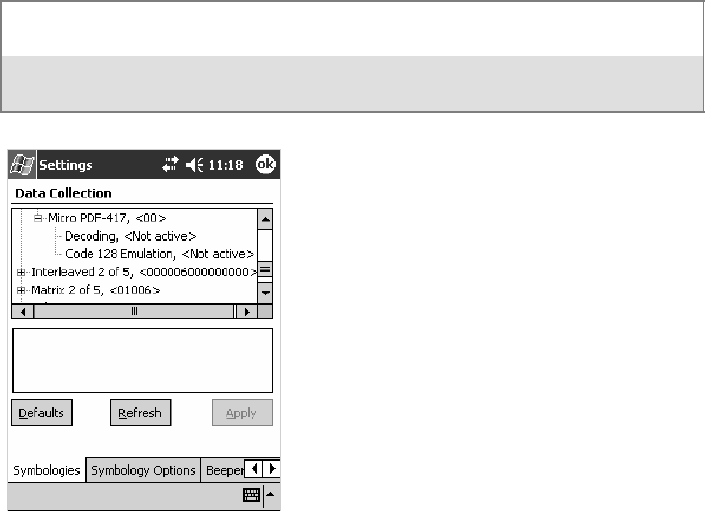
Configurable SettingsAppendix —A
308 700 Series Color Mobile Computer User’s Manual
Micro PDF417
Micro PDF417 is a multi-row symbology derived from and closely based
on PDF417 (page 306). A limited set of symbology sizes is available, to-
gether with a fixed level of error correction for each symbology size. Note
that this is not available when you use an imager with your 700 Color Com-
puter.
Action
Tap (+) to expand the PDF417 parameter, tap (+) to expand the Micro
PDF417 parameter, select a setting to be changed, then select an option to
change this setting.
SNMP OID
1.3.6.1.4.1.1963.15.3.3.1.1.27.1
Options
Decoding 0
1
Not active (default)
Active
Code 128 Emulation 0
1
Not active (default)
Active
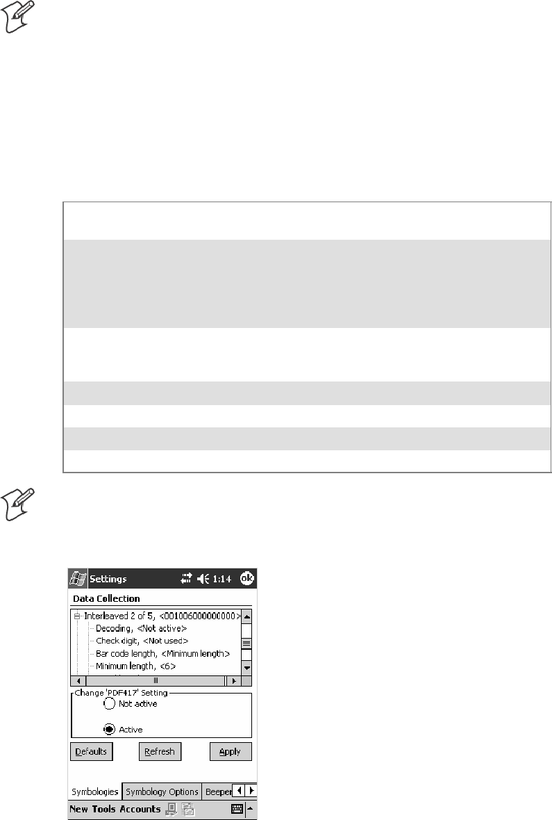
Configurable SettingsAppendix —A
309700 Series Color Mobile Computer User’s Manual
Interleaved 2 of 5
Interleaved 2 of 5 (I 2 of 5) is a high-density, self-checking, continuous,
numeric symbology used mainly in inventory distribution and the automo-
bile industry.
Note: An Interleaved 2 of 5 bar code label must be at least three characters
long for the 700 Color Computer to scan and decode correctly.
Action
Tap (+) to expand the Interleaved 2 of 5 parameter, select the setting to be
changed, then tap an option to change this setting or select an option from
the drop-down list.
SNMP OID
1.3.6.1.4.1.1963.15.3.3.1.1.23.1
Options
Decoding 0
1
Not active (default)
Active
Check digit 0
1
2
3
4
Not used (default)
Mod 10 transmitted
Mod 10 not transmitted
French CIP transmitted
French CIP not transmitted
Bar code length 0
1
2
Any length
Minimum length (default)
Fixed lengths
Minimum length 003–254 Minimum length 3–254 (default is 6)
Fixed length 1 003–254 Fixed bar code length 3–254 (default is 3)
Fixed length 2 003–254 Fixed bar code length 3–254 (default is 3)
Fixed length 3 003–254 Fixed bar code length 3–254 (default is 3)
Note:IfBar code length =“1”thenMinimum length is entered. If Bar
code length =“2” then Fixed length 1,Fixed length 2,orFixed length 3 is
entered.
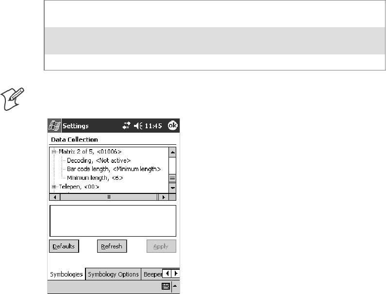
Configurable SettingsAppendix —A
310 700 Series Color Mobile Computer User’s Manual
Matrix 2 of 5
Matrix 2 of 5 is a numerical symbology. Note that this is not available when
you use an imager with your 700 Color Computer.
Action
Tap (+) to expand the Matrix 2 of 5 parameter, select the setting to be
changed, then tap an option to change this setting or select an option from
the drop-down list.
SNMP OID
1.3.6.1.4.1.1963.15.3.3.1.1.24.1
Options
Decoding 0
1
Not active (default)
Active
Bar code length 0
1
Any length
Minimum length (default)
Minimum length 001–254 Minimum length 1–254 (default is 6)
Note:IfBar code length =“1”thenMinimum length is entered.
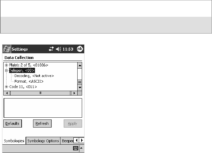
Configurable SettingsAppendix —A
311700 Series Color Mobile Computer User’s Manual
Telepen
Telepen is an alphanumeric, case-sensitive, full ASCII symbology. Note
that this is not available when you use an imager with your 700 Color Com-
puter.
Action
Tap (+) to expand the Telepen parameter, select the setting to be changed,
then tap an option to change this setting.
SNMP OID
1.3.6.1.4.1.1963.15.3.3.1.1.25.1
Options
Decoding 0
1
Not active (default)
Active
Format 0
1
ASCII (default)
Numeric
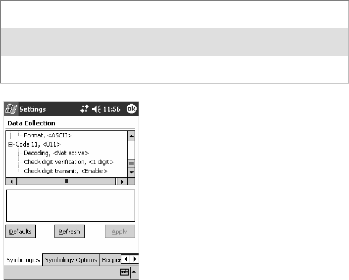
Configurable SettingsAppendix —A
312 700 Series Color Mobile Computer User’s Manual
Code 11
Code 11 is a high density, discrete numeric symbology that is extensively
used in labeling telecommunications components and equipment. Note
that this is not available when you use an imager with your 700 Color Com-
puter.
Action
Tap (+) to expand the Code 11 parameter, select the setting to be
changed, then tap an option to change this setting.
SNMP OID
1.3.6.1.4.1.1963.15.3.3.1.1.26.1
Options
Decoding 0
1
Not active (default)
Active
Check digit verification 1
2
1 digit (default)
2 digits
Check digit transmit 0
1
Disable
Enable (default)
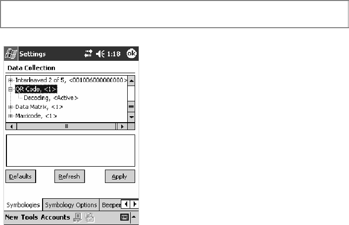
Configurable SettingsAppendix —A
313700 Series Color Mobile Computer User’s Manual
QR Code
QR Code (Quick Response Code) is a two-dimensional matrix symbology
containing dark and light square data modules. It has position detection
patterns on three of its four corners and features direct encodation of the
Japanese Kana-Kanji character set. It can encode up to 2509 numeric or
1520 alphanumeric characters and offers three levels of error detection.
Note that this is not available when you use a laser scanner with your 700 Col-
or Computer or if you are using a 730 Computer.
Action
Tap (+) to expand the QR Code parameter, select the setting to be
changed, then tap an option to change this setting or select an option from
the drop-down list.
SNMP OID
1.3.6.1.4.1.1963.15.3.3.1.1.35.1
Options
Decoding 0
1
Not active
Active (default)
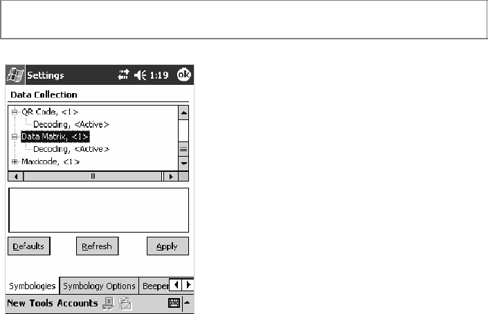
Configurable SettingsAppendix —A
314 700 Series Color Mobile Computer User’s Manual
Data Matrix
A two-dimensional matrix symbology, which is made of square modules
arranged within a perimeter finder pattern. The symbology utilizes Error
Checking and Correcting (ECC) algorithm with selectable levels for data
error recovery and Cyclic Redundancy Check algorithm to validate the
data. The character set includes either 128 characters conforming to ISO
646 (ANSI X3.4 - 1986) or 256 extended character set. Maximum capac-
ity of a symbol is 2335 alphanumeric characters, 1556 8-bit byte charac-
ters or 3116 numeric digits. Note that this is not available when you use a
laserscannerwithyour700ColorComputerorifyouareusinga730Com-
puter.
Action
Tap (+) to expand the Data Matrix parameter, select the setting to be
changed, then tap an option to change this setting.
SNMP OID
1.3.6.1.4.1.1963.15.3.3.1.1.34.1
Options
Decoding 0
1
Not active
Active (default)
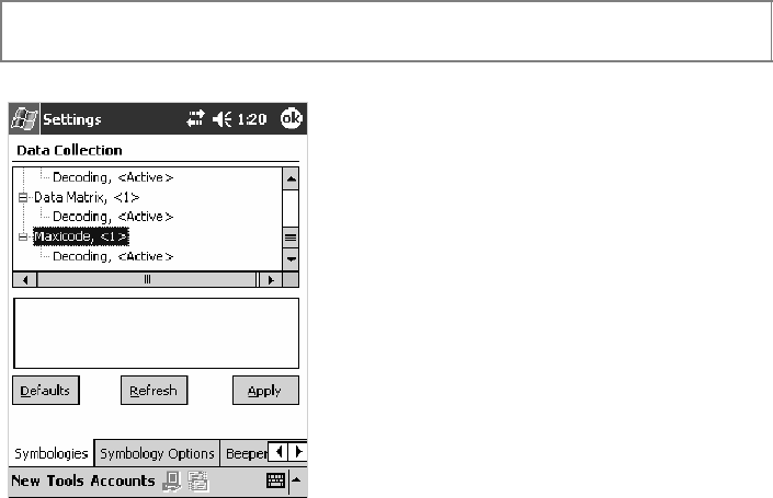
Configurable SettingsAppendix —A
315700 Series Color Mobile Computer User’s Manual
MaxiCode
MaxiCode is a fixed-size 2-D matrix symbology which is made up of offset
rows of hexagonal elements arranged around a unique circular finder pat-
tern. ASCII data is encoded in six-bit symbol characters. The symbol con-
tains 33 rows which are alternately 30 and 29 elements wide. There are
five different code sets. A single MaxiCode symbol can encode up to 93
characters of data. Note that this is not available when you use a laser scanner
withyour700ColorComputerorifyouareusinga730Computer.
Action
Tap (+) to expand the MaxiCode parameter, select the setting to be
changed, then tap an option to change this setting.
SNMP OID
1.3.6.1.4.1.1963.15.3.3.1.1.33.1
Options
Decoding 0
1
Not active
Active (default)
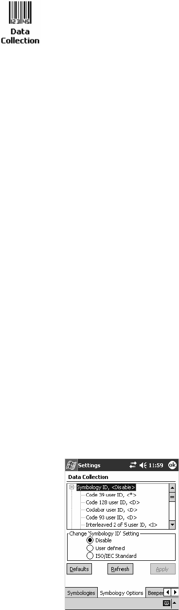
Configurable SettingsAppendix —A
316 700 Series Color Mobile Computer User’s Manual
Symbology Options
To access the settings from the 700 Color Computer, tap Start >Settings
>theSystem tab>theData Collection icon to access its control panel
applet.
Use the right and left arrows to scroll to the Symbology Options tab, then
tap this tab to access its parameters. The following are parameters for bar
code symbology options. Note that these are listed in the order of their
appearance within the Symbology Options tab.
Symbology ID
Identifies the bar code symbology in which data is encoded by prepending
a user-specified symbology identifier to the data. You can prepend one of
these types of character strings to identify the symbology:
SUser-defined ASCII Character (Option 1):
A user-defined symbology identifier is a single ASCII character. You can
assign a custom identifier character to each bar code symbology. Note
that this is not available when you use an imager with your 700 Color
Computer.
SAIM ISO/IEC Standard (Option 2 — Required to define symbology IDs):
The AIM Standard has a three-character structure which indicates the
symbology and optional features. See the AIM ISO/IEC Standard for
information.
Action
Select Symbology ID, then select an option to change this parameter set-
ting. Tap (+) to expand the Symbology ID parameter, then select any of
the user ID parameters listed. See the top of the next page for a sample screen
of the Code 39 user ID.
SNMP OID
1.3.6.1.4.1.1963.15.3.3.4.1.22.1
Options
0 Disable (default)
1 User defined (disabled when using an imager)
2 ISO/IEC Standard
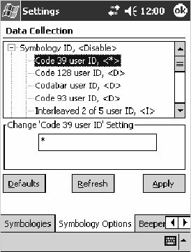
Configurable SettingsAppendix —A
317700 Series Color Mobile Computer User’s Manual
Code 39 User ID
If “1” was selected in the Symbology ID parameter, you can set your own
ASCII character to identify Code 39 bar code data. Note that this is not
available when you use an imager with your 700 Color Computer.
Action: Tap (+) to expand the Symbology ID parameter, select the Code 39 user
ID parameter, then enter a user ID value to change this parameter setting.
SNMP OID: 1.3.6.1.4.1.1963.15.3.3.4.1.3.1
Options: xwhere xis a single ASCII character. Default is asterisk (*).
Code 128 User ID
If “1” was selected in the Symbology ID parameter, you can set your own
ASCII character to identify Code 128 bar code data. Note that this is not
available when you use an imager with your 700 Color Computer.
Action: Tap (+) to expand the Symbology ID parameter, select the Code 128 user
ID parameter, then enter a user ID value to change this parameter setting.
SNMP OID: 1.3.6.1.4.1.1963.15.3.3.4.1.5.1
Options: xwhere xis a single ASCII character. Default is asterisk (*).
Codabar User ID
If “1” was selected in the Symbology ID parameter, you can set your own
ASCII character to identify Codabar bar code data. Note that this is not
available when you use an imager with your 700 Color Computer.
Action: Tap (+) to expand the Symbology ID parameter, select the Codabar user
ID parameter, then enter a user ID value to change this parameter setting.
SNMP OID: 1.3.6.1.4.1.1963.15.3.3.4.1.2.1
Options: xwhere xis a single ASCII character. Default is D.
Configurable SettingsAppendix —A
318 700 Series Color Mobile Computer User’s Manual
Code 93 User ID
If “1” was selected in the Symbology ID parameter, you can set your own
ASCII character to identify Code 93 bar code data. Note that this is not
available when you use an imager with your 700 Color Computer.
Action: Tap (+) to expand the Symbology ID parameter, select the Code 93 user
ID parameter, then enter a user ID value to change this parameter setting.
SNMP OID: 1.3.6.1.4.1.1963.15.3.3.4.1.4.1
Options: xwhere xis a single ASCII character. Default is asterisk (*).
Interleaved 2 of 5 User ID
If “1” was selected in the Symbology ID parameter, you can set your own
ASCII character to identify Interleaved 2 of 5 bar code data. Note that this
is not available when you use an imager with your 700 Color Computer.
Action: Tap (+) to expand the Symbology ID parameter, select the Interleaved 2
of 5 user ID parameter, then enter a user ID value to change this parame-
ter setting.
SNMP OID: 1.3.6.1.4.1.1963.15.3.3.4.1.10.1
Options: xwhere xis a single ASCII character. Default is I (not lowercase L).
PDF417 User ID
If “1” was selected in the Symbology ID parameter, you can set your own
ASCII character to identify PDF417 bar code data. Note that this is not
available when you use an imager with your 700 Color Computer.
Action: Tap (+) to expand the Symbology ID parameter, select the PDF417 user
ID parameter, then enter a user ID value to change this parameter setting.
SNMP OID: 1.3.6.1.4.1.1963.15.3.3.4.1.12.1
Options: xwhere xis a single ASCII character. Default is an asterisk (*).
MSI User ID
If “1” was selected in the Symbology ID parameter, you can set your own
ASCII character to identify MSI bar code data. Note that this is not avail-
able when you use an imager with your 700 Color Computer.
Action: Tap (+) to expand the Symbology ID parameter, select the MSI user ID
parameter, then enter a user ID value to change this parameter setting.
SNMP OID: 1.3.6.1.4.1.1963.15.3.3.4.1.11.1
Options: xwhere xis a single ASCII character. Default is D.
Configurable SettingsAppendix —A
319700 Series Color Mobile Computer User’s Manual
Plessey User ID
If “1” was selected in the Symbology ID parameter, you can set your own
ASCII character to identify Plessey bar code data. Note that this is not
available when you use an imager with your 700 Color Computer.
Action: Tap (+) to expand the Symbology ID parameter, select the Plessey user
ID parameter, then enter a user ID value to change this parameter setting.
SNMP OID: 1.3.6.1.4.1.1963.15.3.3.4.1.13.1
Options: xwhere xis a single ASCII character. Default is D.
Standard 2 of 5 User ID
If “1” was selected in the Symbology ID parameter, you can set your own
ASCII character to identify Standard 2 of 5 bar code data. Note that this is
not available when you use an imager with your 700 Color Computer.
Action: Tap (+) to expand the Symbology ID parameter, select the Standard 2 of
5userIDparameter, then enter a user ID value to change this parameter
setting.
SNMP OID: 1.3.6.1.4.1.1963.15.3.3.4.1.23.1
Options: xwhere xis a single ASCII character. Default is D.
UPC A User ID
If “1” was selected in the Symbology ID parameter, you can set your own
ASCII character to identify UPC-A (Universal Product Code) bar code
data. Note that this is not available when you use an imager with your 700
Color Computer.
Action: Tap (+) to expand the Symbology ID parameter, select the UPC A user
ID parameter, then enter a user ID value to change this parameter setting.
SNMP OID: 1.3.6.1.4.1.1963.15.3.3.4.1.6.1
Options: xwhere xis a single ASCII character. Default is A.
UPC E User ID
If “1” was selected in the Symbology ID parameter, you can set your own
ASCII character to identify UPC-E bar code data. Note that this is not
available when you use an imager with your 700 Color Computer.
Action: Tap (+) to expand the Symbology ID parameter, select the UPC E user
ID parameter, then enter a user ID value to change this parameter setting.
SNMP OID: 1.3.6.1.4.1.1963.15.3.3.4.1.7.1
Options: xwhere xis a single ASCII character. Default is E.
Configurable SettingsAppendix —A
320 700 Series Color Mobile Computer User’s Manual
EAN 8 User ID
If “1” was selected in the Symbology ID parameter, you can set your own
ASCII character to identify EAN-8 bar code data. Note that this is not
available when you use an imager with your 700 Color Computer.
Action: Tap (+) to expand the Symbology ID parameter, select the EAN 8 user
ID parameter, then enter a user ID value to change this parameter setting.
SNMP OID: 1.3.6.1.4.1.1963.15.3.3.4.1.8.1
Options: xwhere xis a single ASCII character. Default is \xFF.
EAN 13 User ID
If “1” was selected in the Symbology ID parameter, you can set your own
ASCII character to identify EAN-13 (European Article Numbering) bar
code data. Note that this is not available when you use an imager with your
700 Color Computer.
Action: Tap (+) to expand the Symbology ID parameter, select the EAN 13 user
ID parameter, then enter a user ID value to change this parameter setting.
SNMP OID: 1.3.6.1.4.1.1963.15.3.3.4.1.9.1
Options: xwhere xis a single ASCII character. Default is F.
Matrix 2 of 5 User ID
If “1” was selected in the Symbology ID parameter, you can set your own
ASCII character to identify Matrix 2 of 5 bar code data. Note that this is
not available when you use an imager with your 700 Color Computer.
Action: Tap (+) to expand the Symbology ID parameter, select the Matrix 2 of 5
user ID parameter, then enter a user ID value to change this parameter
setting.
SNMP OID: 1.3.6.1.4.1.1963.15.3.3.4.1.24.1
Options: xwhere xis a single ASCII character. Default is D.
Telepen User ID
If “1” was selected in the Symbology ID parameter, you can set your own
ASCII character to identify Telepen bar code data. Note that this is not
available when you use an imager with your 700 Color Computer.
Action: Tap (+) to expand the Symbology ID parameter, select the Telepen user
ID parameter, then enter a user ID value to change this parameter setting.
SNMP OID: 1.3.6.1.4.1.1963.15.3.3.4.1.25.1
Options: xwhere xis a single ASCII character. Default is an asterisk (*).
Configurable SettingsAppendix —A
321700 Series Color Mobile Computer User’s Manual
Code 11 User ID
If “1” was selected in the Symbology ID parameter, you can set your own
ASCII character to identify Code 11 bar code data. Note that this is not
available when you use an imager with your 700 Color Computer.
Action: Tap (+) to expand the Symbology ID parameter, select the Code 11 user
ID parameter, then enter a user ID value to change this parameter setting.
SNMP OID: 1.3.6.1.4.1.1963.15.3.3.4.1.16.1
Options: xwhere xis a single ASCII character. Default is asterisk (*).
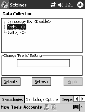
Configurable SettingsAppendix —A
322 700 Series Color Mobile Computer User’s Manual
Prefix
Prepends a string of up to 20 ASCII characters to all scanned data.
Action
Tap the Prefix parameter, then enter a prefix value to change this parame-
ter setting.
SNMP OID
1.3.6.1.4.1.1963.15.3.3.4.1.29.1
Options
Acceptable values are up to 20 ASCII characters. Embedded null
(<NUL >) characters are not allowed. Default is no characters (disabled).
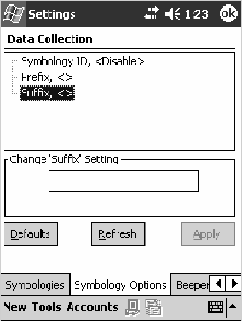
Configurable SettingsAppendix —A
323700 Series Color Mobile Computer User’s Manual
Suffix
Appends a string of up to 20 ASCII characters to all scanned data.
Action
Tap the Suffix parameter, then enter a suffix value to change this parame-
ter setting.
SNMP OID
1.3.6.1.4.1.1963.15.3.3.4.1.30.1
Options
Acceptable values are up to 20 ASCII characters. Embedded null
(<NUL >) characters are not allowed. Default is no characters (disabled).

Configurable SettingsAppendix —A
324 700 Series Color Mobile Computer User’s Manual
Beeper/LED
To access the settings from the 700 Color Computer, tap Start >Settings
>theSystem tab>theData Collection icon to access its control panel
applet.
Use the right and left arrows to scroll to the Beeper/LED tab, then tap this
tab to access its parameters.
Most of these functions are not available when using an imager. The following
table shows which functions are supported either by an imager or by a
laser scanner.
Beeper Function Imager Laser Scanner
Beeper X
Beeper Volume X
Beeper Frequency X
Good Read Beeps X
Good Read Beep Duration X
The following are parameters for features on the 700 Color Computer.
Note that these are listed in the order of their appearance.
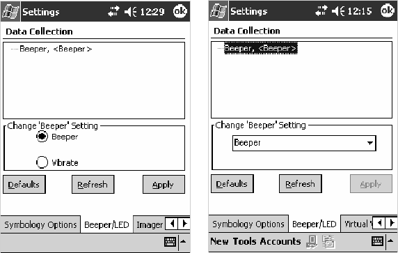
Configurable SettingsAppendix —A
325700 Series Color Mobile Computer User’s Manual
Beeper
Sets the volume for the good read beep. Note that this is not available when
youusealaserscannerwithyour700ColorComputer.
Action
Tap the Beeper parameter, then select an option to change this parameter
setting.
SNMP OID
1.3.6.1.4.1.1963.15.3.1.4.1.6.1
Options
1 Beeper (default)
4Vibrate(not supported on 730 Computers)
700 Color with Imager Screen 730 Screen
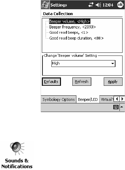
Configurable SettingsAppendix —A
326 700 Series Color Mobile Computer User’s Manual
Beeper Volume
Sets the volume for the good read beep. Note that this is not available when
you use an imager with your 700 Color Computer.
Action
Tap the Beeper volume parameter, then select an option to change this
parameter setting.
SNMP OID
1.3.6.1.4.1.1963.15.3.1.4.1.6.1
Options
0Low
1High(default)
2Medium
3Off
4Vibrate
Disabling the Volume
To disable the beeper, tap Start >Settings >thePersonal tab > Sounds &
Notifications >theVolume tab, drag the System volume slider bar to the
left “Silent” position, then tap ok to exit this applet. See Chapter 1,
“Introduction“ for more information.
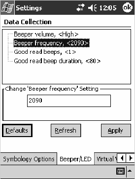
Configurable SettingsAppendix —A
327700 Series Color Mobile Computer User’s Manual
Beeper Frequency
Sets the frequency for the good read beep. Note that this is not available
when you use an imager with your 700 Color Computer.
Action
Tap the Beeper frequency parameter, then enter a frequency value to
change this parameter setting.
SNMP OID
1.3.6.1.4.1.1963.15.3.1.4.1.7.1
Options
1000–4095 (default is 2090)
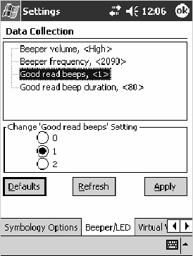
Configurable SettingsAppendix —A
328 700 Series Color Mobile Computer User’s Manual
Good Read Beeps
Sets the number of good read beeps. Note that this is not available when you
useanimagerwithyour700ColorComputer.
Action
Tap the Good read beeps parameter, then select an option to change this
parameter setting.
SNMP OID
1.3.6.1.4.1.1963.15.3.1.4.1.8.1
Options
0 No beeps
1 One beep (default)
2 Two beeps
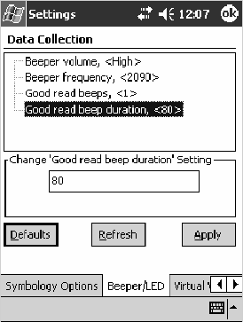
Configurable SettingsAppendix —A
329700 Series Color Mobile Computer User’s Manual
Good Read Beep Duration
Sets the duration of the good read beep. Note that this is not available when
you use an imager with your 700 Color Computer.
Action
Tap the Good read beep duration parameter, then enter a duration value
to change this parameter setting.
SNMP OID
1.3.6.1.4.1.1963.15.3.1.4.1.9.1
Options
0–2550 Beep duration in milliseconds. (default is 80)
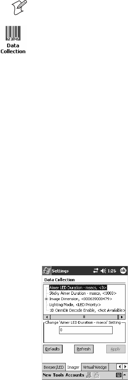
Configurable SettingsAppendix —A
330 700 Series Color Mobile Computer User’s Manual
Imager
Note: These instructions do not apply to the 730 Computer.
To access the settings from the 700 Color Computer, tap Start >Settings
>theSystem tab > Data Collection to access its control panel applet.
Use the right and left arrows to scroll to the Imager tab, then tap this tab
to access its parameters.
The following are parameters for the imager. Note that these are listed in
the order of their appearance within the Imager tab.
Aimer LED Duration
The Aimer LED Duration controls the time the Aimer LED is turned on
when the scan button is pressed. After this time, images are captured for
decoding. The purpose is to position the Aimer LED on the bar code sym-
bol before attempting to decode the bar code. Note that this is not available
whenyouusealaserscannerwithyour700ColorComputer.
Action
Tap the Aimer LED Duration parameter, then enter a value to change this
setting. Note that values must be in 50 ms increments, such as 500, 650,
or 32500. Values not entered in 50 ms increments are rounded down. For
example, 2489 ms is rounded down to 2450 ms, 149 ms is rounded down
to 100 ms, etc..
SNMP OID
1.3.6.1.4.1.1963.15.3.3.3.1.1.21.1
Options
0–65500 ms (Default is 0)
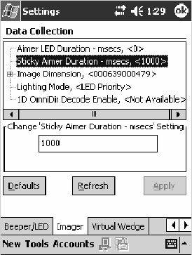
Configurable SettingsAppendix —A
331700 Series Color Mobile Computer User’s Manual
Sticky Aimer Duration
The Sticky Aimer Duration controls the time the Aimer LED stays on af-
ter the a bar code read completes or after the trigger button is released.
Note that this is not available when you use a laser scanner with your 700 Col-
or Computer.
Action
Tap the Sticky Aimer Duration parameter, then enter a value to change
this setting. Note that values must be in 50 ms increments, such as 500,
650, or 32500. Values not entered in 50 ms increments are rounded
down. For example, 2489 ms is rounded down to 2450 ms, 149 ms is
rounded down to 100 ms, etc..
SNMP OID
1.3.6.1.4.1.1963.15.3.3.3.1.1.24.1
Options
0–65535 ms (Default is 1000)
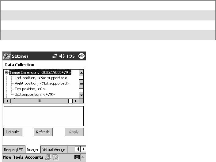
Configurable SettingsAppendix —A
332 700 Series Color Mobile Computer User’s Manual
Image Dimension
The image dimensions control the vertical size of the image for decoding.
This can restrict the image to one bar code when otherwise, there might be
more than one bar code in the image to be decoded. Note that this is not
available when you use a laser scanner with your 700 Color Computer.
Action
Tap the Image dimension parameter, select the position to be changed,
then tap an option or enter a value to change this position.
SNMP OID
1.3.6.1.4.1.1963.15.3.3.3.1.1.22.1
Options
Left position 0Not supported
Right position 0Not supported
Top position 0–478 Position in pixels (Default is 0)
Bottom position 0–479 Position in pixels (Default is 479)
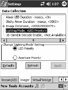
Configurable SettingsAppendix —A
333700 Series Color Mobile Computer User’s Manual
Lighting Mode
TheLightingModesetsthelightingmodeoftheimager.Whensetto
“LED Priority,” the imager depends more on ambient lighting to illumi-
nate the bar code for reading. When set to “Aperture Priority,” the imager
uses its built-in LED to illuminate the bar code for reading. Note that this
is not available when you use a laser scanner with your 700 Color Computer.
Action
Tap the Lighting Mode parameter, then select an option to change this
parameter setting.
SNMP OID
1.3.6.1.4.1.1963.15.3.3.3.1.1.23.1
Options
0LEDPriority(default)
1 Aperture Priority
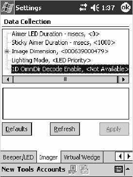
Configurable SettingsAppendix —A
334 700 Series Color Mobile Computer User’s Manual
1D OmniDir Decode Enable
The 1D OmniDir Decode Enable affects the scanning abilities of the
IT4000 Imager. With 1D omni directional enabled, the imager is able to
decode images and bar code labels regardless of the orientation of the label.
With 1D omni directional disabled, the imager only decodes labels in the
direction of the aimer LED. Note that this is not available when you use a
laser scanner with your 700 Color Computer.
Action
Tap the 1D OmniDir Decode Enable parameter,then select an option to
change this parameter setting.
SNMP OID
1.3.6.1.4.1.1963.15.3.3.3.1.1.25.1
Options
0Disabled
1 Enabled (default)
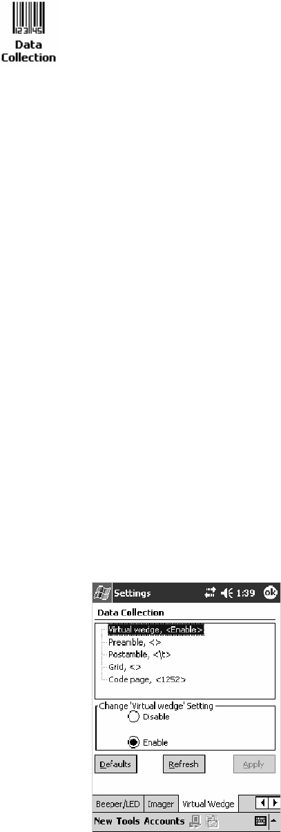
Configurable SettingsAppendix —A
335700 Series Color Mobile Computer User’s Manual
Virtual Wedge
To access the settings from the 700 Color Computer, tap Start >Settings
>theSystem tab > Data Collection to access its control panel applet.
Use the right and left arrows to scroll to the Virtual Wedge tab, then tap
this tab to access its parameters.
The following are parameters for the virtual wedge scanner. Note that these
are listed in the order of their appearance within the Virtual Wedge tab.
Virtual Wedge
Enables or disables the virtual wedge for the internal scanner. The virtual
wedge retrieves scanned Automatic Data Collection (ADC) data and sends
it to the keypad driver so that the 700 Color Computer can receive and
interpret the data as keypad input.
Because the virtual wedge translates incoming data into keypad input, the
size of the keypad buffer limits the effective length of the label to 128
characters. Longer labels may be truncated. For labels of more than 128
characters, you need to develop an application that bypasses the keypad
buffer.
Action
Tap the Virtual Wedge parameter, then tap an option to change this pa-
rameter setting.
SNMP OID
1.3.6.1.4.1.1963.15.3.2.1.1.2.1
Options
0Disable
1Enable(default)
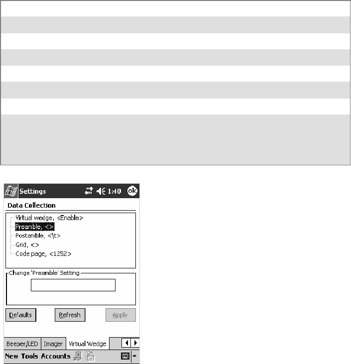
Configurable SettingsAppendix —A
336 700 Series Color Mobile Computer User’s Manual
Preamble
Sets the preamble that precedes any data you scan with the 700 Color
Computer. Common preambles include a data location number or an op-
erator number.
Action
Tap the Preamble parameter, then enter a preamble value to change this
parameter setting.
SNMP OID
1.3.6.1.4.1.1963.15.3.2.1.1.3.1
Syntax
ADdata
where data is any acceptable values up to 31 ASCII characters. Embedded
null (<NUL >) characters are not allowed. Below are the non-printing
characters you can use for Virtual Wedge Preambles. Default is blank.
\a Alert (bell)
\b Backspace
\f Form Feed
\n New line/line feed
\r Carriage return
\t Horizontal tab
\v Vertical tab
\xnnnn nnnn is up to four HEX digits. Use leading zeros to fill out to four digits to
ensure proper conversion. For example, to prepend the character M to
scanned data, set the Preamble to either 1) M, or 2) x004D, where 4D is the
HEX equivalent for an uppercase M.

Configurable SettingsAppendix —A
337700 Series Color Mobile Computer User’s Manual
Note: When you enter the AD command without data, the preamble is
disabled. If you want to use quotation marks or the following combina-
tions of characters as part of the appended data, separate those characters
from the AD command with quotes. If you do not use quotes as described
here, the 700 Color Computer interprets the characters as another config-
uration command:
AD
AE
AF
KC
BV
EX
DF
Example
To use the two-character string BV as a preamble, scan this command (as a
Code 39 label) or send this command through the network:
$+AD“BV”
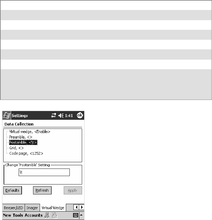
Configurable SettingsAppendix —A
338 700 Series Color Mobile Computer User’s Manual
Postamble
Sets the postamble that is appended to any data you scan with the 700
Color Computer. Common postambles include cursor controls, such as
tabs or carriage return line feeds.
Action
Tap the Postamble parameter, then enter a postamble value to change this
parameter setting.
SNMP OID
1.3.6.1.4.1.1963.15.3.2.1.1.4.1
Syntax
AEdata
where data is any acceptable values up to 31 ASCII characters. Embedded
null (<NUL >) characters are not allowed. Below are the non-printing
characters you can use for Virtual Wedge Postambles:
\a Alert (bell)
\b Backspace
\f Form Feed
\n New line/line feed
\r Carriage return
\t Horizontal tab (default)
\v Vertical tab
\xnnnn nnnn is up to four HEX digits. Use leading zeros to fill out to four digits to
ensure proper conversion. For example, to prepend the character M to
scanned data, set the Preamble to either 1) M, or 2) x004D, where 4D is the
HEX equivalent for an uppercase M.

Configurable SettingsAppendix —A
339700 Series Color Mobile Computer User’s Manual
Note: When you enter the AE command without data, the postamble is
disabled. If you want to use quotation marks or the following combina-
tions of characters as part of the appended data, separate those characters
from the AE command with quotes. If you do not use quotes as described
here, the 700 Color Computer interprets the characters as another config-
uration command.
AD
AE
AF
KC
BV
EX
DF
Example
To use the two-character string BV as a postamble, scan this command (as
a Code 39 label) or send this command through the network:
$+AE“BV”
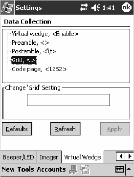
Configurable SettingsAppendix —A
340 700 Series Color Mobile Computer User’s Manual
Grid
Sets the virtual wedge grid, which filters the data coming from this 700
Color Computer. The data server supports data filtering, which allows you
to selectively send scanned data. The virtual wedge grid is similar to the
“format” argument of the C Runtime Library scan function.
Action
Tap the Grid parameter, then enter a grid value to change this parameter
setting.
SNMP OID
1.3.6.1.4.1.1963.15.3.2.1.1.5.1
Syntax
AF<symID> filter-expression= > editing-expression
where:
S<symID>
The AIM symbology ID (optional).
Sfilter-expression
Any character string that includes valid filter expression values. Go to
the SDK User’s Manual provided with your Windows CE/PocketPC SDK
for a list of valid filter expression values.
Sediting-expression
Any character string that includes valid editing expression values. Go to
the SDK User’s Manual provided with your Windows CE/PocketPC SDK
for a list of valid editing expression values.
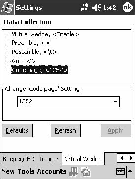
Configurable SettingsAppendix —A
341700 Series Color Mobile Computer User’s Manual
Code Page
Setsthevirtualwedgecodepage.Thecodepagecontrolsthetranslation
from the character set of the raw collected data to Unicode, which is the
character set expected by Windows CE applications. The default code page
is 1252, which is the Windows Latin 1 (ANSI) character set.
Action
Tap the Code Page parameter, then select an option to change this param-
eter setting.
SNMP OID
1.3.6.1.4.1.1963.15.3.2.1.1.6.1
Options
Theonlyacceptablevalueforthecodepageparameteris“1252,” which is
the default.
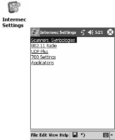
Configurable SettingsAppendix —A
342 700 Series Color Mobile Computer User’s Manual
Intermec Settings Control Panel Applet
You may have the Intermec Settings control panel applet. Information
about the settings you can configure with this applet is described in the
Intermec Computer Command Reference Manual. The online manual is
available from the Intermec web site at www.intermec.com.
See “Scanner Control and Data Transfer”intheIntermec Windows CE/
Pocket PC Software Developer’s Kit (SDK) User’s Manual shipped with the
Software Developer’s Kit (SDK) for information about data collection
functions.
To access the settings from the 700 Color Computer, tap Start >Settings
>theSystem tab > Intermec Settings to access its control panel applet.

Configurable SettingsAppendix —A
343700 Series Color Mobile Computer User’s Manual
SNMP Control Panel Applet
Note: This applet is not available in units with PSM Build 3.00 or newer.
To determine your PSM build version, tap Start >Programs >
File Explorer >thePSMinfo text file.
If your unit has PSM Build 3.00 or newer, then you may have the Intermec
Settings control panel applet in place of the SNMP applet. Information
about the settings you can configure with the Intermec Settings applet is
described in the Intermec Computer Command Reference Manual.The
online manual is available from the Intermec web site at
www.intermec.com.
Simple Network Management Protocol (SNMP) parameters include iden-
tification information, security encryption, security community strings,
and traps.
To access the settings from the 700 Color Computer, tap Start >Settings
>theSystem tab > SNMP to access its control panel applet.
Tap a tab to access its menus. These tabs represent three groups of settings
or parameters:
SSecurity (starting on the next page)
STraps (starting on page 349)
SIdentification (starting on page 351)
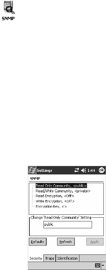
Configurable SettingsAppendix —A
344 700 Series Color Mobile Computer User’s Manual
Security
To access the settings from the 700 Color Computer, tap Start >Settings
>theSystem tab > SNMP >theSecurity tab to access its parameters.
The following are parameters that affect encryption and community
strings. Note that these are listed in the order of their appearance within the
Security tab.
Read Only Community
Sets the read-only community string for this 700 Color Computer, which
is required for processing of SNMP get and get next requests.
Action
Tap the Read Only Community parameter, then enter a community
string to change this parameter setting.
SNMP OID
1.3.6.1.4.1.1963.10.5.1.2.0
Options
The read-only community string can be up to 128 ASCII characters. De-
fault is Public.
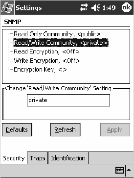
Configurable SettingsAppendix —A
345700 Series Color Mobile Computer User’s Manual
Read/Write Community
Sets the read/write community string, which is required for processing of
SNMP set requests by this 700 Color Computer. An SNMP packet with
this name as the community string will also process SNMP get and next
requests.
Action
Tap the Read/Write Community parameter, then enter a community
string to change this parameter setting.
SNMP OID
1.3.6.1.4.1.1963.10.5.1.3.0
Options
Theread/writecommunitystringcanbeupto128ASCIIcharacters.De-
fault is Private.
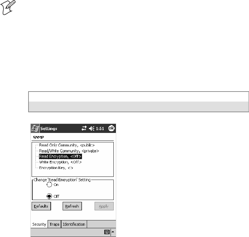
Configurable SettingsAppendix —A
346 700 Series Color Mobile Computer User’s Manual
Read Encryption
Sets the packet-level mode of security for SNMP read-only requests. If you
enable read encryption, all received SNMP get and get next packets have
to be encrypted or the packet will not be authorized. If encryption is en-
abled, you can only use software provided by Intermec Technologies.
Note: To enable security encryption, you also need to set the Security En-
cryption Key (page 348).
Action
Tap the Read Encryption parameter, then select an option to change this
parameter setting.
SNMP OID
1.3.6.1.4.1.1963.10.5.1.4.0
Options
1On SNMPgetandgetnextpacketsmustbeencrypted
2Off SNMP packets do not have to be encrypted (default)
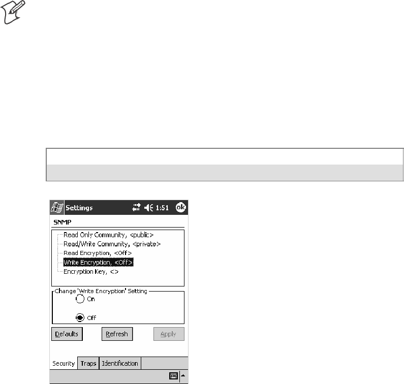
Configurable SettingsAppendix —A
347700 Series Color Mobile Computer User’s Manual
Write Encryption
Sets the packet-level mode of security for SNMP read/write requests. If
you enable write encryption, all SNMP packets that are received with the
read/write community string have to be encrypted or the packet will not
be authorized. You need to use software from Intermec Technologies that
supports encryption.
Note: To enable security encryption, you also need to set the Security En-
cryption Key (page 348).
Action
Tap the Write Encryption parameter, then select an option to change this
parameter setting.
SNMP OID
1.3.6.1.4.1.1963.10.5.1.5.0
Options
1On SNMP packets must be encrypted
2Off SNMP packets do not have to be encrypted (default)
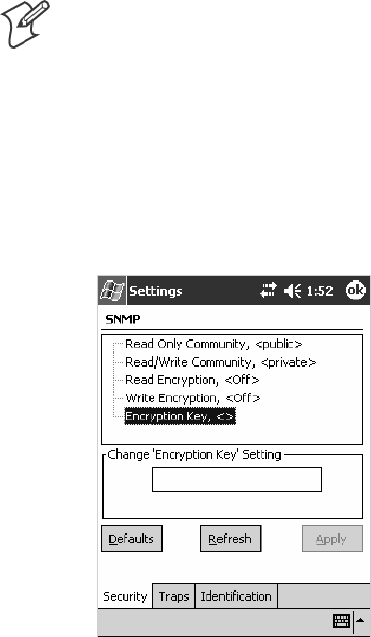
Configurable SettingsAppendix —A
348 700 Series Color Mobile Computer User’s Manual
Encryption Key
Identifies the key that this 700 Color Computer uses to encrypt or deci-
pher SNMP packets. Encryption is used only by software provided by In-
termec Technologies. If encryption is enabled, SNMP management plat-
forms will not be able to communicate with the 700 Color Computer.
The encryption key is returned encrypted.
Action
Tap the Encryption Key parameter, then enter a security encryption key
valuetochangethisparametersetting.
Note: You also need to set either Read Encryption (page 346) or Write
Encryption (page 347) or both.
SNMP OID
1.3.6.1.4.1.1963.10.5.1.6.0
Options
The encryption key can be from 4 to 20 ASCII characters. Default is
NULL.
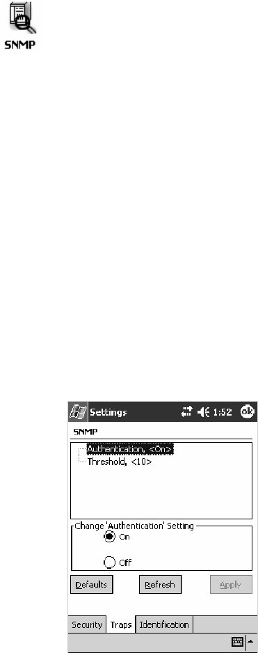
Configurable SettingsAppendix —A
349700 Series Color Mobile Computer User’s Manual
Traps
To access the settings from the 700 Color Computer, tap Start >Settings
>theSystem tab > SNMP >theTraps tab to access its parameters.
The following are authentication and threshold parameters for traps. Note
that these are listed in the order of their appearance within the Traps tab.
Authentication
Determines whether to send authentication traps. When trap authentica-
tion is enabled, an authentication trap is sent if an SNMP packet is re-
ceived by the master agent with an invalid community string.
Action
Tap the Authentication parameter, then select an option to change this
parameter setting.
SNMP OID
1.3.6.1.4.1.1963.10.5.2.2.0
Options
1On(default)
2Off
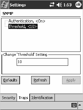
Configurable SettingsAppendix —A
350 700 Series Color Mobile Computer User’s Manual
Threshold
Determines the maximum number of traps per second that the master
agent generates. If the threshold is reached, the trap will not be sent.
Action
Tap the Threshold parameter, then enter a threshold value to change this
parameter setting.
SNMP OID
1.3.6.1.4.1.1963.10.5.2.3.0
Options
Any positive integer value. Default is 10.
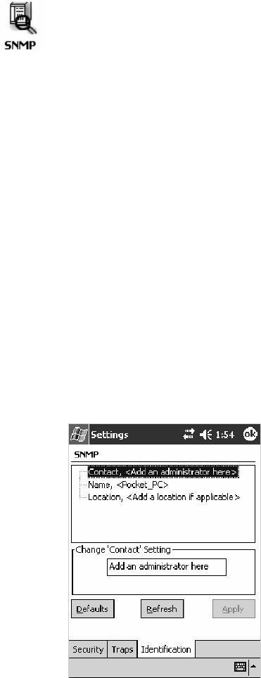
Configurable SettingsAppendix —A
351700 Series Color Mobile Computer User’s Manual
Identification
To access the settings from the 700 Color Computer, tap Start >Settings
>theSystem tab > SNMP >theIdentification tab to access its
parameters.
The following are parameters for contact, location, and name information
for support purposes. Note that these are listed in the order of their appear-
ance within the Identification tab.
Contact
Sets the contact information for the person responsible for this 700 Color
Computer.
Action
Tap the Contact parameter, then enter the name of your contact represen-
tative to change this parameter setting.
SNMP OID
1.3.6.1.2.1.1.4.0
Options
The identification contact may be up to 255 ASCII characters. Default is
no characters or blank.
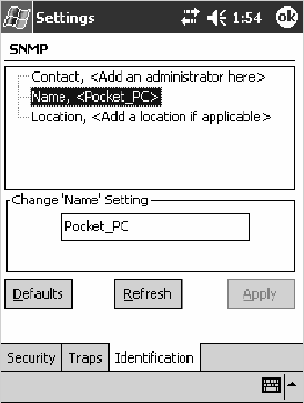
Configurable SettingsAppendix —A
352 700 Series Color Mobile Computer User’s Manual
Name
Sets the assigned name for this 700 Color Computer.
Action
Tap the Name parameter, then enter the name of your 700 Color Com-
puter to change this parameter setting.
SNMP OID
1.3.6.1.2.1.1.5.0
Options
The identification name may be up to 255 ASCII characters. Default is no
characters or blank.
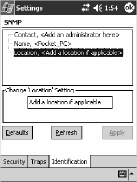
Configurable SettingsAppendix —A
353700 Series Color Mobile Computer User’s Manual
Location
Sets the identification location for this 700 Color Computer, such as
“Shipping.”
Action
Tap the Location parameter, then enter the location of where your 700
Color Computer to change this parameter setting.
SNMP OID
1.3.6.1.2.1.1.6.0
Options
The identification location may be up to 255 ASCII characters. Default is
no characters or blank.
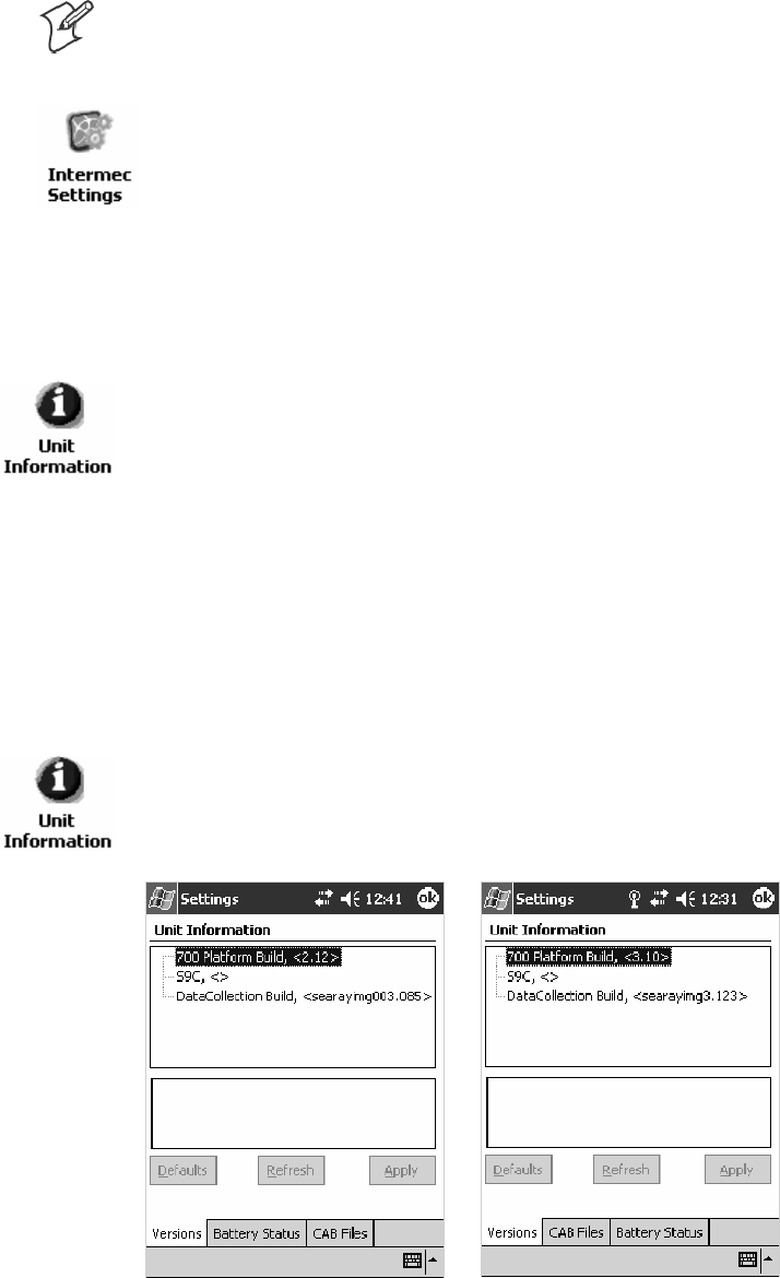
Configurable SettingsAppendix —A
354 700 Series Color Mobile Computer User’s Manual
Unit Information Control Panel Applet
Note: This applet is not available in units with PSM Build 3.00 or newer.
To determine your PSM build version, tap Start >Programs >
File Explorer >thePSMinfo text file.
If your unit has PSM Build 3.00 or newer, then you may have the Intermec
Settings control panel applet in place of the Unit Information applet.
Information about the settings you can configure with the Intermec
Settings applet is described in the Intermec Computer Command Reference
Manual. The online manual is available from the Intermec web site at
www.intermec.com.
Unit Information is a read-only control panel applet that provides infor-
mation about your 700 Color Computer, such as software version builds,
available CAB files, and the internal battery status.
To access the settings from the 700 Color Computer, tap Start >Settings
>theSystem tab > Unit Information to access its control panel applet.
Tap a tab to access its menus. These tabs represent three groups of settings
or parameters:
SVersions (next paragraph)
SBattery Status (starting on page 355)
SCAB Files (starting on page 356)
Versions
You can view the latest software build version on your 700 Color
Computer by accessing the Unit Information control panel applet.
To access the settings from the 700 Color Computer, tap Start >Settings
>theSystem tab > Unit Information >theVersions tab to view the latest
software build version. Tap ok to exit this information.
700 Color Screen 730 Screen
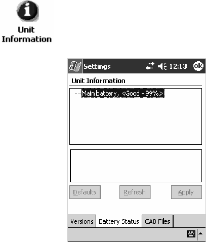
Configurable SettingsAppendix —A
355700 Series Color Mobile Computer User’s Manual
Battery Status
You can view the battery status for your 700 Color Computer by accessing
the Unit Information control panel applet.
To access the settings from the 700 Color Computer, tap Start >Settings
>theSystem tab > Unit Information >theBattery Status tab to view the
current status. Tap ok to exit this information.
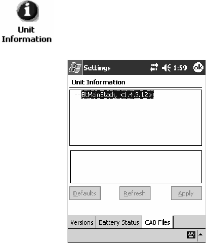
Configurable SettingsAppendix —A
356 700 Series Color Mobile Computer User’s Manual
CAB Files
You can view the latest developer or released version of each CAB file from
Intermec Technologies Corporation that are installed in your 700 Color
Computer via the Unit Information control panel applet. Custom CAB
files are not displayed in this applet. See the Software Tools User’s Manual for
more information about these files.
To access the information from the 700 Color Computer, tap Start >
Settings >theSystem tab > Unit Information >theCAB Files tab to view
thecurrentCABfileversions.Tapok to exit this information.
When a CAB file is built, a registry entry is created with a build number
for that file. This CAB Files control panel applet looks for a registry key
for each CAB file installed. When the registry entry is found, the CAB file
name and version number information are displayed. If a CAB file has not
been installed, then its information is not displayed.
Below is a list of CAB files from Intermec Technologies that are available
foryour700ColorComputerwiththeirlatestdeveloperorreleasedver-
sion of the software build. Should you need to add any of these to your
700 Color Computer, contact an Intermec representative.
SBtMainStack:
Installation of the Main Bluetooth Stack is handled automatically as part
of the operating system boot-up procedure. See Chapter 4, “Network
Support,” for more information about Bluetooth wireless printing.
SComm Port Wedge:
ThesoftwarebuildfortheCommPortWedge.Note that the Comm Port
Wedge CAB file is available on the Intermec Developer’s Library CD.
SNPCPTest:
This installs a Norand
®
Portable Communications Protocol (NPCP)
Printing test application which will print to an Intermec
®
4815, 4820,
or 6820 Printer. See Chapter 5, “Printer Support,” for more information.
Configurable SettingsAppendix —A
357700 Series Color Mobile Computer User’s Manual
SS9C Upgrade:
Installs the files needed to upgrade the S9C scanner firmware. See the
700 Color Management Tools portion of the Intermec Developer’s Library
CD for more information about upgrading the firmware.
SSDK:
Installs the Intermec Software Developer’s Kit (SDK). See the SDK
User’s Manual for more information.
SWinCfg:
Configures the NRINET.INI file, launches the NRINet client, and
loads and unloads the LAN and WLAN device drivers.
SWireless Printing Sample:
Installs a sample application that developers can use for reference when
they are developing their own Wireless Printing applications. The
sourcecodeforthisapplicationisincludedaspartoftheWirelessPrint-
ing SDK on the Intermec Developer’s Library CD.See the SDK User’s
Manual for more information.
SActiveX Control Tools:
This lists some of the CAB files that may be available with which to
install ActiveX Control Tools. See the SDK Online Help for more infor-
mation.
SAXCommunication:
Communication controls that transmit or receive messages from in-
put connections.
SAXFileTransfer:
File transfer controls that transmit and receive files using the Trivial
File Transfer Protocol (TFTP).
SAXReaderCommand:
Reader command functions that modify and retrieve configuration
information from your 700 Color Computer.
SAXVWedge:
The virtual wedge control that retrieves scanned ADC data and sends
it to the keyboard driver to interpret data as keyboard input.
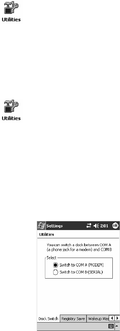
Configurable SettingsAppendix —A
358 700 Series Color Mobile Computer User’s Manual
Utilities Control Panel Applet
The Utilities control panel applet examines and modifies settings and op-
erational modes of specific hardware and software on the 700 Color Com-
puter, including the dock switch, registry storage, wakeup mask, and ap-
plication launch keys.
To access the settings from the 700 Color Computer, tap Start >Settings
>theSystem tab > Utilities to access its control panel applet.
Use the left and right arrows to scroll through the tabs along the bottom of
the control panel applet, then tap a tab to access its menus. These tabs rep-
resent the following groups of settings or parameters:
SDock Switch (next paragraph)
SRegistry Save (page 359)
SWakeup Mask (page 360)
SApp Launch (page 361)
Dock Switch
From the 700 Color Computer, tap Start >Settings >theSystem tab >
Utilities >theDock Switch tab to access the Dock Switch control panel
applet.
Use this applet to control the position of the dock switch. This can be set
either to a COM A (phone jack for a modem) position or to a COM B
(serial) position.
If switched to COM B and suspended, the terminal has the following be-
havior:
SIf the 700 Color Computer is on charge, the dock switch remains
switched to COM B.
SIf the 700 Color Computer is off charge, the dock switch switches to
COMAandremaininthispositionuntilthe700ColorComputerre-
sumes charge.
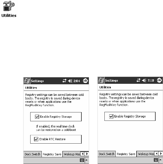
Configurable SettingsAppendix —A
359700 Series Color Mobile Computer User’s Manual
Registry Save
From the 700 Color Computer, tap Start >Settings >theSystem tab >
Utilities >theRegistry Save tab to access the Registry Save control panel
applet.
For Windows Mobile 2003, the only medium available for saving the reg-
istry is the Flash File System (PSM). Registry data is stored in the
“\Flash_File_Store\Registry” path. Check Enable Registry Storage to en-
able this function.
To ensure that the 700 Color Computer restores the real-time clock after a
cold-boot, check the Enable RTC Restore option. Note that this does not
apply to the 730 Computer.
700 Color Screen 730 Screen
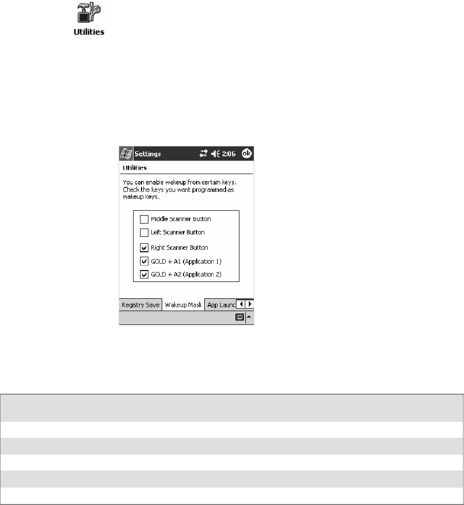
Configurable SettingsAppendix —A
360 700 Series Color Mobile Computer User’s Manual
Wakeup Mask
From the 700 Color Computer, tap Start >Settings >theSystem tab >
Utilities >theWakeup Mask tab to access the Wakeup Mask control pan-
el applet.
This applet programs three scanner buttons and the A1 and A2 application
keys to be “wakeup” or resume keys. That is, to prompt the 700 Color
Computer to “wake up” or resume activity after going to “sleep” as a result
of being inactive after a length of time. This information will remain be-
tween warm and cold boots.
Check the appropriate box, then tap ok to apply your settings.
Based on your setting, do the following to “wake up” the 700 Color Com-
puter.
If you select:
Then do this on
Numeric Keyboard
Then do this on
Alphanumeric Keyboard
Middle Scanner Button SqueezethebuttonontheScanHandle SqueezethebuttonontheScanHandle
Left Scanner Button Squeeze the left scanner button Squeeze the left scanner button
Right Scanner Button Squeeze the right scanner button Squeeze the right scanner button
GOLD+A1(Application1) Press [Gold]
ba
Press [Gold/White]
cA
GOLD+A2(Application2) Press [Gold]
b4
Press [Gold/White]
cB
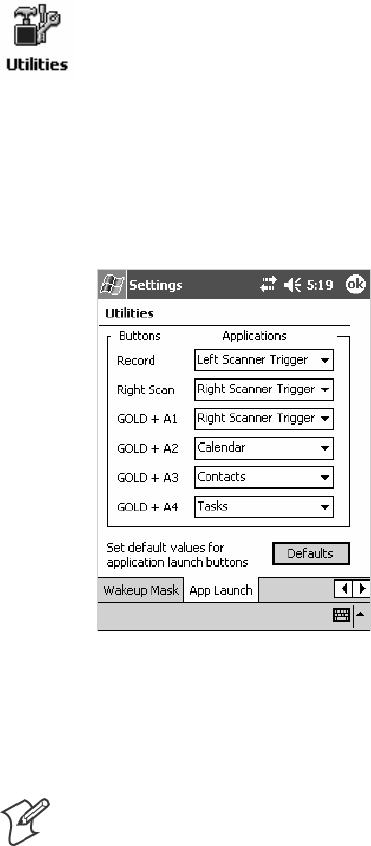
Configurable SettingsAppendix —A
361700 Series Color Mobile Computer User’s Manual
App Launch
From the 700 Color Computer, tap Start >Settings >theSystem tab >
Utilities , then scroll to the right to tap the App Launch tab to access the
Application Launch control panel applet.
This applet programs or maps two scanner buttons and four application
keys to start up to six applications. Note that the left scanner button also acts
as the record button.
For700ColorComputerswitheitheralaserscanneroranimager,
default mappings are shown in the following illustration.
For700ColorComputerswithouteitheralaserscanneroranimager,
the default maps the Record, Calendar, Contacts, and Tasks applications
the top four and the A3 and A4 buttons are ”unassigned” or available for
two more applications.
Note: Record, Calendar, Contacts, and Tasks are Pocket PC applications.
See Chapter 2, “Windows Mobile 2003,” for more information about these
applications.
STo assign an application to a button, select an application from the ap-
plicable drop-down list box.
STo assign a new application, select the “Add new application” option,
which brings up an Open File dialog and browse SD or CF storage
cards for new applications.
STo disable or unmap a currently mapped application from a correspon-
ding button, select “unassigned” from the applicable drop-down list.
STo restore these buttons to their defaults, tap Defaults in the lower
right corner.

Configurable SettingsAppendix —A
362 700 Series Color Mobile Computer User’s Manual
Note; You cannot map an application to more than one button. Should
you assign the same application to two buttons, a verification prompt will
appear after the second button to confirm whether you want to remap the
application. If you tap Yes, the applet changes the first button to “unas-
signed” and map the application to the second button.
Note: All changes are activated immediately upon selection.

Configurable SettingsAppendix —A
363700 Series Color Mobile Computer User’s Manual
Wireless Network Control Panel Applet
Note:SeeChapter4,“Network Support,” for information about the
802.11b or 802.11b/g radio module.
About the Wireless Network
Your wireless adapter (network interface card) connects to wireless net-
works of two types: infrastructure networks and ad-hoc networks.
SInfrastructure networks get you onto your corporate network and the
internet. Your 700 Color Computer establishes a wireless connection to
an access point, which links you to the rest of the network. When you
connect to a network via an access point, you are using the 802.11b or
802.11b/g infrastructure mode.
SAd-hoc networks are private networks shared between two or more cli-
ents, even with no access point.
Each wireless network is assigned a name (or Service Set Identifier —
SSID) to allow multiple networks to coexist in the same area without in-
fringement.
Intermec Technologies recommends using security measures with wireless
networks to prevent unauthorized access to your network and to ensure
your privacy of transmitted data. The following are required elements for
secure networks:
SAuthentication by both the network and the user
SAuthentication is cryptographically protected
STransmitted data
There are many schemes available for implementing these features.
Terminology
Below are terms you may encounter as you configure your wireless net-
work:
SCKIP (Cisco Key Integrity Protocol)
This is Cisco’s version of the TKIP protocol, compatible with Cisco
Airnet products.
SEAP (Extensible Authentication Protocol)
802.11b or 802.11b/g uses this protocol to perform authentication.
This is not necessarily an authentication mechanism, but is a common
framework for transporting actual authentication protocols. Intermec
Technologies provides a number of EAP protocols for you to choose the
bestforyournetwork.
Configurable SettingsAppendix —A
364 700 Series Color Mobile Computer User’s Manual
STKIP (Temporal Key Integrity Protocol)
This protocol is part of the IEEE 802.11i encryption standard for wire-
less LANs., which provides per-packet key mixing, a message integrity
check and a re-keying mechanism, thus overcoming most of the weak
points of WEP. This encryption is more difficult to crack than the stan-
dard WEP. Weak points of WEP include:
SNo Installation Vector (IV) reuse protection
SWeak keys
SNo protection against message replay
SNo detection of message tampering
SNo key updates
SWEP (Wired Equivalent Privacy) encryption
With preconfigured WEP, both the client 700 Color Computer and
access point are assigned the same key, which can encrypt all data be-
tween the two devices. WEP keys also authenticate the 700 Color Com-
puter to the access point — unless the 700 Color Computer can prove
it knows the WEP key, it is not allowed onto the network.
WEP keys are only needed if they are expected by your clients. There
are two types available: 64-bit (5-character strings, 12345) (default) and
128-bit (13-character strings, 1234567890123). Enter these as either
ASCII (12345) or Hex (0x3132333435).
SWPA (Wi-Fi Protected Access)
This is an enhanced version of WEP that does not rely on a static,
shared key. It encompasses a number of security enhancements over
WEP, including improved data encryption via TKIP and 802.11b or
802.11b/g authentication with EAP.
WiFi Alliance security standard is designed to work with existing
802.11 products and to offer forward compatibility with 802.11i.
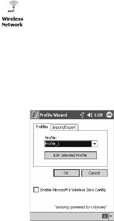
Configurable SettingsAppendix —A
365700 Series Color Mobile Computer User’s Manual
Configuring Your Wireless Network
To start 802.11b or 802.11b/g communications on the 700 Color
Computer, tap Start
>
Settings >theSystem tab > Wireless Network to
access the Profile Wizard for the 802.11b or 802.11b/g radio module.
A profile contains all the information necessary to authenticate you to the
network, such as login name, password or certificate, and protocols by
which you are authenticated.
You can have up to four profiles for different networks. For example, you
may have different login names or passwords on different networks, or you
may use a password on one network, and a certificate on another.
Use the Profiles page to select and configure between the networking envi-
ronments assigned to this 802.11b or 802.11b/g radio.
SProfile:
Tap the drop-down list to choose between four different profiles as-
signed to this unit, then tap Edit Select Profile, make the changes need-
ed for this profile (starting on the next page),thentapOK to return to
the Profiles page.
SEnable Microsoft’s Wireless Zero Config
Check this box to enable Microsoft’s Wireless Zero Config application.
This effectively disables the Intermec software solution for 802.11b or
802.11b/g, including configuration via the CORE application and the
Wireless Network control panel applet.
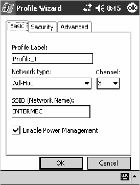
Configurable SettingsAppendix —A
366 700 Series Color Mobile Computer User’s Manual
Basic
Use the Basic page to set the network type, name, and manage battery
power for this profile. Tap ok or OK to return to the Profiles page.
SProfile Label:
Enterauniquenameforyourprofile.
SNetwork type:
Tap the drop-down list to select either “Infrastructure” if your network
uses access points to provide connectivity to the corporate network or
internet; or “Ad-Hoc” to set up a private network with one or more par-
ticipants.
SChannel:
If you selected “Ad-Hoc” for the network type, select the channel on
which you are communicating with others in your network. There are
up to 11 channels available.
SSSID (Network Name):
This assumes the profile name unless another name is entered in this field.
If you want to connect to the next available network or are not familiar
with the network name, enter “ANY” in this field. Consult your LAN
administrator for network names.
SEnable Power Management:
Check this box to conserve battery power (default), or clear this box to
disable this feature.
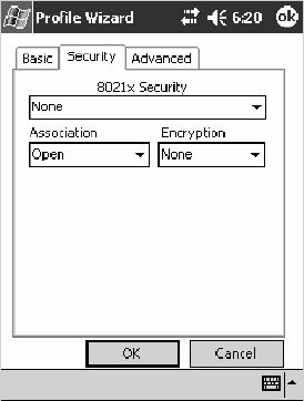
Configurable SettingsAppendix —A
367700 Series Color Mobile Computer User’s Manual
Security
The following are available from the 8021x Security drop-down list. Note
that the last four methods are available if you have purchased the security pack-
age. Contact your Intermec representative for information.
SNone (below)
SPEAP (page 370)
STLS (page 374)
STTLS (page 377)
SLEAP (page 381)
None
Use “None” to disable 802.11b or 802.11b/g Security and enable either
WEP or WPA-PSK encryption.
To Disable 802.1x Security
1Set 8021x Security as “None.”
2Set Association to “Open.”
3Set Encryption to “None.”
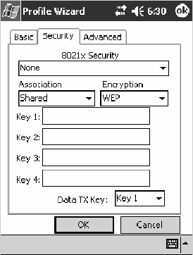
Configurable SettingsAppendix —A
368 700 Series Color Mobile Computer User’s Manual
To Enable WEP Encryption
1Set 8021x Security as “None.”
2Set Association to either “Open” if WEP keys are not required; or
“Shared” when WEP keys are required for association.
3Set Encryption to “WEP.” See page 364 for information about WEP
encryption.
4If you had set Association to “Shared,” then select a data transmission
key from the Data TX Key drop-down list near the bottom of this
screen, then enter the encryption key for that data transmission in the
appropriate Key # field.
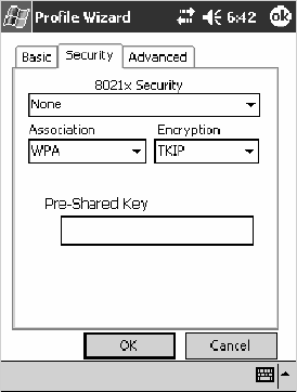
Configurable SettingsAppendix —A
369700 Series Color Mobile Computer User’s Manual
ToEnableWPAEncryptionUsingaPresharedKey
1Set 8021x Security as “None.”
2Set Association to “WPA.” See page 364 for information about WPA
encryption.
3Skip Encryption as it is automatically set to “TKIP.” See page 364 for
more information about TKIP.
4Enter the temporal key as ASCII (12345) in the Pre-Shared Key field.
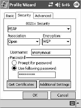
Configurable SettingsAppendix —A
370 700 Series Color Mobile Computer User’s Manual
PEAP (Protected EAP)
This protocol is suitable for performing secure authentication against Win-
dows domains and directory services. It is comparable to EAP-TTLS (see
page 377), both in its method of operation and its security, though not as
flexible. This does not support the range of inside-the-tunnel authentica-
tion methods supported by EAP-TTLS. Microsoft and Cisco both support
this protocol.
Use “PEAP” to configure the use of PEAP as an authentication protocol
and to select “Open,” “WPA,” or “Network EAP” as an association mode.
To Enable PEAP with an Open Association
1Set 8021x Security as “PEAP.”
2Set Association to “Open.”
3Skip Encryption as it is automatically set to “WEP.” See page 364 for
information about WEP encryption.
4Enter your unique user name and password to use this protocol. Select
Prompt for password to have the user enter this password each time to
access the protocol; or leave Use following password as selected to auto-
matically use the protocol without entering a password.
5Tap Get Certificates to obtain or import server certificates. See page
380 for more information.
6Tap Additional Settings to assign an inner PEAP authentication and set
options for server certificate validation and trust. See page 373 for more
information.

Configurable SettingsAppendix —A
371700 Series Color Mobile Computer User’s Manual
To Enable PEAP with WPA Encryption
1Set 8021x Security as “PEAP.”
2Set Association to “WPA.” See page 364 for information about WPA
encryption.
3Skip Encryption as it is automatically set to “TKIP.” See page 364 for
more information about TKIP.
4Enter your unique user name and password to use this protocol. Select
Prompt for password to have the user enter this password each time to
access the protocol, or leave Use following password as selected to auto-
matically use the protocol without entering a password.
5Tap Get Certificates to obtain or import server certificates. See page
380 for more information.
6Tap Additional Settings to assign an inner PEAP authentication and set
options for server certificate validation and trust. See page 373 for more
information.
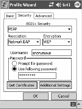
Configurable SettingsAppendix —A
372 700 Series Color Mobile Computer User’s Manual
To Enable PEAP with Network EAP
1Set 8021x Security as “PEAP.”
2Set Association to “Network EAP.” See page 363 for information about
EAP.
3Set Encryption to either “WEP” or “CKIP.” See page 363 for informa-
tion about CKIP and page 364 for information about WEP encryption.
4Enter your unique user name and password to use this protocol. Select
Prompt for password to have the user enter this password each time to
access the protocol, or leave Use following password as selected to auto-
matically use the protocol without entering a password.
5Tap Get Certificates to obtain or import server certificates. See page
380 for more information.
6Tap Additional Settings to assign an inner PEAP authentication and set
options for server certificate validation and trust. See page 373 for more
information.
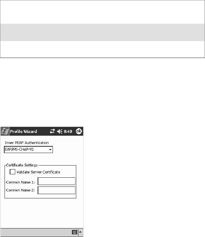
Configurable SettingsAppendix —A
373700 Series Color Mobile Computer User’s Manual
Additional Settings
1Select an authentication method from the Inner PEAP Authentication
drop-down list.
EAP/MS-CHAP-V2 Authenticates against a Windows Domain Controller and
other non-Windows user databases. This is Microsoft’s
implementation of PEAP.
EAP/Token Card Use with token cards. The password value entered is never
cached. This is Cisco’s implementation of PEAP.
EAP/MD5-Challenge Message Digest 5. A secure hashing authentication algo-
rithm.
2Check Validate Server Certificate to verify the identity of the authenti-
cation server based on its certificate when using TTLS or PEAP.
3Enter the Common Names of trusted servers. Note that if these fields are
left blank, the server certificate trust validation is not performed or required.
4Click ok to return to the Security page.
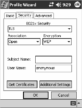
Configurable SettingsAppendix —A
374 700 Series Color Mobile Computer User’s Manual
TLS (EAP-TLS)
EAP-TLS is a protocol that is based on the TLS (Transport Layer Security)
protocol widely used to secure web sites. This requires both the user and
authentication server have certificates for mutual authentication. While
crypticallystrong,thisrequirescorporationsthatdeploythistomaintaina
certificate infrastructure for all their users.
Use “TLS” to configure the use of EAP-TLS as an authentication protocol,
and select either “Open” or “WPA” as an association mode.
ToEnableTLSwithanOpenAssociation
1Set 8021x Security as “TLS.”
2Set Association to “Open.”
3Skip Encryption as it is automatically set to “WEP.” See page 364 for
information about WEP encryption.
4EnteryouruniqueSubject Name and User Name to use this protocol.
5Tap Get Certificates to obtain or import server certificates. See page
380 for more information.
6Tap Additional Settings to set options for server certificate validation
and trust. See page 376 for more information.
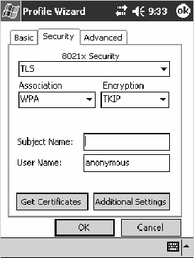
Configurable SettingsAppendix —A
375700 Series Color Mobile Computer User’s Manual
To Enable TLS with WPA Encryption
1Set 8021x Security as “TLS.”
2Set Association to “WPA.” See page 364 for information about WPA
encryption.
3Skip Encryption as it is automatically set to “TKIP.”See page 364 for
more information about TKIP.
4EnteryouruniqueSubject Name and User Name as credentials for this
profile.
5Tap Get Certificates to obtain or import server certificates. See page
380 for more information.
6Tap Additional Settings to set options for server certificate validation
and trust. See page 376 for more information.
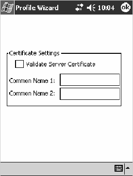
Configurable SettingsAppendix —A
376 700 Series Color Mobile Computer User’s Manual
Additional Settings
1Check Validate Server Certificate to verify the identity of the authenti-
cation server based on its certificate when using PEAP or TLS.
2Enter the Common Names of trusted servers. Note that if these fields are
left blank, the server certificate trust validation is not performed or required.
3Click ok to return to the Security page.
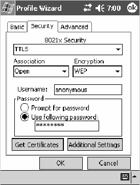
Configurable SettingsAppendix —A
377700 Series Color Mobile Computer User’s Manual
TTLS (EAP-Tunneled TLS)
This protocol provides authentication like EAP-TLS (see page 374) but
does not require certificates for every user. Instead, authentication servers
are issued certificates. User authentication is done using a password or oth-
er credentials that are transported in a securely encrypted “tunnel” estab-
lished using server certificates.
EAP-TTLS works by creating a secure, encrypted tunnel through which
you present your credentials to the authentication server. Thus, inside
EAP-TTLS there is another inner authentication protocol that you must
configure via Additional Settings.
Use“TTLS”toconfiguretheuseofEAP-TTLSasanauthenticationpro-
tocol, and select either “Open” or “WPA” as an association mode.
ToEnableTTLSwithanOpenAssociation(default configuration)
1Set 8021x Security as “TTLS.”
2Set Association to “Open.”
3Skip Encryption as it is automatically set to “WEP.” See page 364 for
information about WEP encryption.
4Enter your unique user name and password to use this protocol. Select
Prompt for password to have the user enter this password each time to
access the protocol, or leave Use following password as selected to auto-
matically use the protocol without entering a password.
5Tap Get Certificates to obtain or import server certificates. See page
380 for more information.
6Tap Additional Settings to assign an inner TTLS authentication and an
inner EAP, and set options for server certificate validation and trust. See
page 379 for more information.
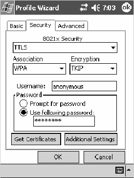
Configurable SettingsAppendix —A
378 700 Series Color Mobile Computer User’s Manual
To Enable TTLS with WPA Encryption
1Set 8021x Security as “TTLS.”
2Set Association to “WPA.” See page 364 for information about WPA
encryption.
3Skip Encryption as it is automatically set to “TKIP.” See page 364 for
more information about TKIP.
4Enter your unique user name and password to use this protocol. Select
Prompt for password to have the user enter this password each time to
access the protocol, or leave Use following password as selected to auto-
matically use the protocol without entering a password.
5Tap Get Certificates to obtain or import server certificates. See page
380 for more information.
6Tap Additional Settings to assign an inner TTLS authentication and an
inner EAP, and set options for server certificate validation and trust. See
page 379 for more information.
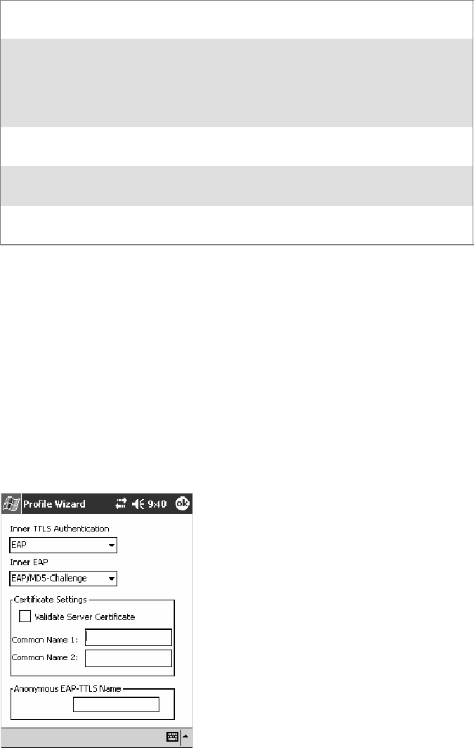
Configurable SettingsAppendix —A
379700 Series Color Mobile Computer User’s Manual
Additional Settings
1Select an authentication protocol from the Inner TTLS Authentication
drop-down list:
PAP Password Authentication Protocol. A simple authentication
protocol that sends security information in the clear.
CHAP Challenge Handshake Authentication Protocol. Use of Radius
to authenticate a terminal without sending security data in the
clear. Authenticates against non-Windows user databases. You
cannot use this if authenticating against a Windows NT Domain
or Active Directory.
MS-CHAP;
MS-CHAP-V2
Authenticates against a Windows Domain Controller and other
non-Windows user databases.
PAP/Token Card Use with token cards. The password value entered is never
cached.
EAP Extensible Authentication Protocol. See page 363 for informa-
tion about EAP.
2If you select “EAP” for the inner authentication protocol, then an inner
EAP protocol from the Inner EAP drop-down list.
3Enter the Common Names of trusted servers. Note that if these fields are
left blank, the server certificate trust validation is not performed or required.
4Check Validate Server Certificate to verify the identity of the authenti-
cation server based on its certificate when using TTLS, PEAP, and TLS.
5Enter the Anonymous EAP-TTLS Name as assigned for public usage.
Use of this outer identity protects your login name or identity.
6Click ok to return to the Security page.
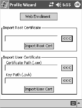
Configurable SettingsAppendix —A
380 700 Series Color Mobile Computer User’s Manual
To Get Certificates
Certificates are pieces of cryptographic data that guarantee a public key is
associated with a private key. They contain a public key and the entity
name that owns the key. Each certificate is issued by a certificate authority.
Usethispagetoimportacertificateontothe700ColorComputer.
Root Certificates
1Tap the <<< button next to the Import Root Certificate field to select
the root certificate (DER-encoded .CER file) to import.
2Click Import Root Cert to install the selected certificate.
User Certificate
1Tap the <<< button next to the Certificate Path field to select the user
certificate (DER-encoded .CER file without the private key) to import.
2Tap the <<< button next to the Key Path field to select the private key
(.PVK file) which corresponds to the user certificate chosen in step 1.
3Tap Import User Cert to install the selected certificate.
Web Enrollment
Tap Web Enrollment to obtain a user certificate over the network from an
IAS Server. Tap ok to return to the Security page.
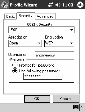
Configurable SettingsAppendix —A
381700 Series Color Mobile Computer User’s Manual
LEAP (Cisco Lightweight EAP)
LEAP is the Cisco Lightweight version of EAP. See page 363 for informa-
tion about EAP.
Use “LEAP” to configure the use of LEAP as an authentication protocol,
select“Open,”“WPA,”or“NetworkEAP”asanassociationmode,oras-
sign Network EAP. Note that this defaults to the Network EAP.
To Enable LEAP with an Open Association
1Set 8021x Security as “LEAP.”
2Set Association to “Open.”
3Skip Encryption as it is automatically set to “WEP.” See page 364 for
information about WEP encryption.
4EnteryouruniqueUser Name to use this protocol.
5Select Prompt for password to have the user enter this password each
time to access the protocol, or leave Use following password as selected
to automatically use the protocol without entering a password.
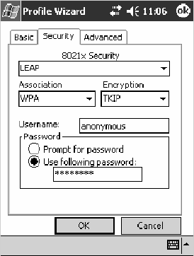
Configurable SettingsAppendix —A
382 700 Series Color Mobile Computer User’s Manual
To Enable LEAP with WPA Encryption
1Set 8021x Security as “LEAP.”
2Set Association to “WPA.” See page 364 for information about WPA
encryption.
3Skip Encryption as it is automatically set to “TKIP.” See page 364 for
more information about TKIP.
4EnteryouruniqueUser Name to use this protocol.
5Select Prompt for password to have the user enter this password each
time to access the protocol, or leave Use following password as selected
to automatically use the protocol without entering a password.
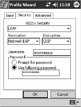
Configurable SettingsAppendix —A
383700 Series Color Mobile Computer User’s Manual
To Enable LEAP with Network EAP
1Set 8021x Security as “LEAP.”
2Set Association to “Network EAP,” an EAP protocol for the network.
See page 363 for information about EAP.
3Set Encryption to either “WEP” or “CKIP.” See page 363 for informa-
tion about CKIP and page 364 for information about WEP encryption.
4EnteryouruniqueUser Name to use this protocol.
5Select Prompt for password to have the user enter this password each
time to access the protocol, or leave Use following password as selected
to automatically use the protocol without entering a password.
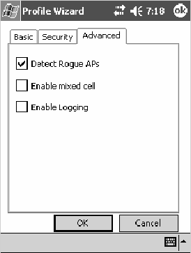
Configurable SettingsAppendix —A
384 700 Series Color Mobile Computer User’s Manual
Advanced
Use this page to configure additional settings for this profile. Tap ok or
OK to return to the Profiles page.
SDetect Rogue APs:
Wireless NICs and APs associate based on the SSID configured for the
NIC. Given an SSID, the BSSID with the strongest signal is often cho-
sen for association. After association, 802.1x authentication may occur
and during authentication credentials to uniquely identify a user —
these are passed between the NIC and the AP.
The base 802.1x technology does not protect the network from “rogue
APs.” These can mimic a legitimate AP to authentication protocols and
user credentials. This provides illegal users ways to mimic legitimate us-
ers and steal network resources and compromise security.
Check this box to detect and report client behavior suspected of being
rogue APs. Once a rouge AP is detected, your 700 Series Computer no
longer associates with that AP until you perform a warm boot.
Clear this box to solve AP connection problems that result when an AP
gets put on the rogue AP list due to inadvertant failed authentications
and not because it is a real rouge.
SEnable mixed cell:
Mixed cell is a profile-dependent setting. If enabled, you can connect to
mixed cell without using WEP, then you can query the cell to deter-
mine whether you can use encryption.
SEnable Logging:
Check this box to log what activity incurs for this profile.
Configurable SettingsAppendix —A
385700 Series Color Mobile Computer User’s Manual
Other Configurable Parameters
The following parameters can be configured by sending reader commands
through the network or from an application. See “Using Reader Com-
mands” on page 387 for more information.
Audio Volume
Changes the volume of all audio signals.
SNMP OID
1.3.6.1.4.1.1963.15.3.1.3.0
Options (Syntax Data for Reader Commands)
0Off
1 Very quiet
2Quiet
3Normal(default)
4Loud
5Veryloud
Automatic Shutoff
Sets the length of time the 700 Color Computer remains on when there is
no activity. When you turn on the 700 Color Computer, it either resumes
exactly where it was when you turned it off or boots and restarts your ap-
plication.
SNMP OID
1.3.6.1.4.1.1963.15.11.3.0
Options (Syntax Data for Reader Commands)
11minute
22minutes
3 3 minutes (default)
44minutes
55minutes
Configurable SettingsAppendix —A
386 700 Series Color Mobile Computer User’s Manual
Backlight Timeout
Sets the length of time that the display backlight remains on. If you set a
longer timeout value, you use the battery power at a faster rate.
SNMP OID
1.3.6.1.4.1.1963.15.13.1.0
Options (Syntax Data for Reader Commands)
10 10 seconds
30 30 seconds
60 1 minute (default)
120 2 minutes
180 3 minutes
240 4 minutes
300 5 minutes
Date/Time
Sets the current date and time.
SNMP OID
Date: 1.3.6.1.4.1.1963.15.501.2.1.0
Time: 1.3.6.1.4.1.1963.15.501.2.2.0
Options (Syntax Data for Reader Commands)
Date Year 0000–9999 (1999)
Month 1–12 (6)
Day 1–31 (1)
Time Hour 0–23 (0)
Minute 0–59 (00)
Second 0–59 (00)
Key Clicks
Enables or disables the keypad clicks. The 700 Color Computer emits a
click each time you press a key or decode a row of a two-dimensional
symbology.
SNMP OID
1.3.6.1.4.1.1963.15.12.1.0
Options (Syntax Data for Reader Commands)
0 Disable clicks
1Enablesoftkeyclicks
2 Enable loud key clicks (default)

Configurable SettingsAppendix —A
387700 Series Color Mobile Computer User’s Manual
Using Reader Commands
After the 700 Color Computer is connected to your network, you can
send the 700 Color Computer a reader command from an application to
perform a task, such as changing the time and date. Some reader com-
mands temporarily override the configuration settings and some change
the configuration settings.
Change Configuration
The Change Configuration command must precede any configuration
command. If you enter a valid string, the 700 Color Computer configura-
tion is modified and the computer emits a high beep. To send the Change
Configuration command through the network, use the
$+ [command]
syntax where command is the two-letter command syntax for the configu-
ration command followed by the value to be set for that command.
You can also make changes to several different commands by using the
$+ [command]...[command n]
syntax. There are seven configuration
command settings that can be changed in this way. See each command for
information on respective acceptable “data” values.
Command Syntax
Audio Volume BVdata
Automatic Shutoff EZdata
Backlight Timeout DFdata
Key Clicks KCdata
Virtual Wedge Grid AFdata
Virtual Wedge Postamble AEdata
Virtual Wedge Preamble ADdata
Note: See pages 336 and 338 for more information about the Virtual
Wedge Postamble and Virtual Wedge Preamble commands.
Example 1
To change the Beep Volume to Off, you can send this string to the 700
ColorComputerthroughthenetwork:
$+BV0
where:
$+ Indicates Change Configuration.
BV Specifies the Audio Volume parameter.
0Specifies a value of Off.
Example 2
To change the Beep Volume to Very Quiet and the Virtual Wedge Grid
to 123:
$+BV1AF123
where:
$+ Indicates Change Configuration
BV1 Specifies Audio Volume, set to Very Quiet (1)
AF123 Specifies Virtual Wedge Grid, set to a value of 123.
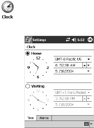
Configurable SettingsAppendix —A
388 700 Series Color Mobile Computer User’s Manual
Set Time and Date
This command sets the date and time on the 700 Color Computer. The
default date and time is June 1, 1999 at 12:00 AM.
From the network, send the following:
/+ yyyymmddhhmmss
where acceptable values for the date are:
yyyy 0000–9999 Year
mm 01–12 Month of the year
dd 01–31 Day of the month
hh 00–23 Hour
mm 00–59 Minutes
ss 00–59 Seconds
You can also set the time and date by using Configuration Management in
Unit Manager, or by using the Clock control panel applet in the Settings
menu. To access this control panel applet, tap Start >Settings >the
System tab>theClock icon to access its control panel applet.

Configurable SettingsAppendix —A
389700 Series Color Mobile Computer User’s Manual
Configuration Bar Codes
You can change some settings on your 700 Color Computer by scanning
the following Code 39 bar code labels.
SYou can use the Data Collection control panel to set the three Virtual
Wedge parameters (starting on page 335).
Note: When you use a bar code creation utility to make a scannable bar
code label, the utility probably adds opening and closing asterisks automat-
ically. Asterisks are included here for translation purposes.
Audio Volume
Note: The Audio Volume parameter information is on page 385.
Turn Audio Off
*$+BV0*
*$+BV0*
Set Audio Volume to very quiet
*$+BV1*
*$+VB1*
Set Audio Volume to quiet
*$+BV2*
*$+BV2*
Set Audio Volume to normal (default)
*$+BV3*
*$+BV3*
Set Audio Volume to loud
*$+BV4*
*$+BV4*
Set Audio Volume to very loud
*$+BV5*
*$+BV5*

Configurable SettingsAppendix —A
390 700 Series Color Mobile Computer User’s Manual
Automatic Shutoff
Note: The Automatic Shutoff parameter information is on page 385.
Set Automatic Shutoff to 1 minute
*$+EZ1*
*$+EZ1*
Set Automatic Shutoff to 2 minutes
*$+EZ2*
*$+EZ2*
Set Automatic Shutoff to 3 minutes (default)
*$+EZ3*
*$+EZ3*
Set Automatic Shutoff to 4 minutes
*$+EZ4*
*$+EZ4*
Set Automatic Shutoff to 5 minutes
*$+EZ5*
*$+EZ5*
Backlight Timeout
Note: The Backlight Timeout parameter information is on page 386.
Backlight Timeout 10 seconds
*$+DF10*
*$+DF10*
Backlight Timeout 30 seconds
*$+DF30*
*$+DF30*
Backlight Timeout 1 minute (default)
*$+DF60*
*$+DF60*

Configurable SettingsAppendix —A
391700 Series Color Mobile Computer User’s Manual
Backlight Timeout 2 minutes
*$+DF120*
*$+DF120*
Backlight Timeout 3 minutes
*$+DF180*
*$+DF180*
Backlight Timeout 4 minutes
*$+DF240*
*$+DF240*
Backlight Timeout 5 minutes
*$+DF300*
*$+DF300*
Key Clicks
Note: The Key Clicks parameter information is on page 386.
Disable key clicks
*$+KC0*
*$+KC0*
Enable soft key clicks
*$+KC1*
*$+KC1*
Enable loud key clicks (default)
*$+KC2*
*$+KC2*
Configurable SettingsAppendix —A
392 700 Series Color Mobile Computer User’s Manual
Virtual Wedge Grid, Preamble, Postamble
The following parameters are user-configurable strings. Refer to a full
ASCII chart for more information.
Grid
ForVirtualWedgeGrid,thefirstpartofthebarcodewouldbethefol-
lowing, which can include a string of up to 240 characters. Parameter in-
formation starts on page 340.
*$+AF
*$+AF
Preamble
ForVirtualWedgePreamble,thefirstpartofthebarcodewouldbebe-
low, followed by a string of up to 31 characters (no <NUL>) and an aster-
isk. Default is no characters. Parameter information is on page 336.
*$+AD
*$+AD
Postamble
For Virtual Wedge Postamble, the first part of the bar code would be be-
low, followed by a string of up to 31 characters (no <NUL>) and an aster-
isk. Default is no characters. Parameter information is on page 338.
*$+AE
*$+AE

393700 Series Color Mobile Computer User’s Manual
Bar Code Symbologies
B
This appendix contains a brief explanation of some of the bar code
symbologies that the 700 Series Color Mobile Computer decodes and ex-
plains some of the general characteristics and uses of these bar code types.
The 700 Color Computer recognizes eleven of the most widely used bar
code symbologies. With bar code symbologies, like languages, there are
many different types. A bar code symbology provides the required flexibil-
ity for a particular inventory tracking system.
A symbology may be for particular industries, such as food and beverage,
automotive, railroad, or aircraft. Some of these industries have established
their own bar code symbology because other symbologies did not meet
their needs.
Without going into great detail on the bar code structure, note that no two
products use the same bar code. Each product gets a unique bar code.
Industries that use a particular type of bar code symbology have formed
regulating committees or are members of national institutes that issue and
keep track of bar codes. This ensures that each organization that contrib-
utes to a particular industry conforms to its standard. Without some form
of governing body, bar coding would not work.
Note: “700 Color” pertains to 740, 741, 750, 751, 760, and 761 Com-
puters unless otherwise noted.
Bar Code SymbologiesAppendix —B
394 700 Series Color Mobile Computer User’s Manual
Codabar
Codabar was for retail price-labeling systems. Today it is widely accepted
by libraries, medical industries, and photo finishing services.
Codabar is a discrete, self-checking code with each character represented
by a stand-alone group of four bars and three intervening spaces.
Four different start or stop characters get defined and designated “a”, “b”,
“c”, and “d”. These start and stop characters are constructed using one
wide bar and two wide spaces. A complete Codabar symbol begins with
one of the start or stop characters followed by some number of data char-
acters and ending in one of the start or stop characters.
Any of the start or stop characters may be used on either end of the sym-
bol. It is possible to use the 16 unique start or stop combinations to identi-
fy label type or other information.
Since Codabar is variable-length, discrete, and self-checking, it is a versa-
tile symbology. The width of space between characters is not critical and
mayvarysignificantlywithinthesamesymbol.Thecharactersetconsists
of “0” through “9”, “-”, “$”, “:”, “/”, “.”, and “+”.
The specific dimensions for bars and spaces in Codabar optimize perfor-
mance of certain early printing and reading equipment. Codabar has 18
different dimensions for bar and space widths. So many different dimen-
sions often result in labels printed out of specification and cause Codabar
printing equipment to be more expensive.
Code 11
Code 11 satisfies the requirements for a very high density, discrete numer-
icbarcode.ThenameCode11derivesfrom11differentdatacharacters
that can be represented, in addition to a start or stop character.
The character set includes the 10 digits and the dash symbol. Each charac-
ter is represented by a stand-alone group of three bars and two intervening
spaces. Although Code 11 is discrete, it is not self-checking. A single print-
ing defect can transpose one character into another valid character. One or
two check digits obtain data security.
The specifications for Code 11 suggest that this code should have a narrow
element width of 7.5 mils. This results in an information density of 15
characters per inch.
Code 39
Code 39 (C39) is the most widely used symbology among the industrial
bar codes. Most major companies, trade associations, and the federal gov-
ernment find this code to fit their needs. The main feature of this symbol-
ogy is the ability to encode messages using the full alphanumeric character
set, seven special characters, and ASCII characters.
Programming for this symbology can be for any length that the application
requires. The application program for the 700 Color Computer handles
symbology at least one character but no more than 32 characters in length.

Bar Code SymbologiesAppendix —B
395700 Series Color Mobile Computer User’s Manual
When programming the computer for Code 39, it is important to set the
symbology limit as close as possible (minimum and maximum bar code
lengths being scanned). Doing so keeps the computer bar code processing
time to a minimum and conserves battery power.
Bar code readers can respond to Uniform Symbology Specification sym-
bols in non-standard ways for particular applications. These methods are
not for general applications, because of the extra programming required.
Code 39 Full ASCII is one example of non-standard code.
Note: See page 389 to scan several Code 39 bar code labels available to
change settings on your 700 Color Computer.
Encoded Code 39 (Concatenation)
If the first data character of a symbol is a space, the reader may be pro-
grammed to append the information contained in the remainder of the
symbol to a storage buffer. This operation continues for all successive sym-
bols that contain a leading space, with messages being added to the end of
previously stored ones. When a message is read which does not contain a
leading space, the contents are appended to the buffer, the entire buffer is
transmitted, and the buffer is cleared.
Encoded Code 39 (Full ASCII)
If the bar code reader is programmed for the task, the entire ASCII charac-
ter set (128 characters) could be coded using two character sequences: a
symbol (“$”,“.”,“%”,“/”) followed by a letter of the alphabet.
Code 93
The introduction of Code 93 provided a higher density alphanumeric
symbology designed to supplement Code 39. The set of data characters in
Code 93 is identical with that offered with Code 39. Each character con-
sists of nine modules arranged into three bars and three spaces.
Code 93 uses 48 of the 56 possible combinations. One of these characters,
represented by a square, is reserved for a start or stop character, four are
used for control characters, and the remaining 43 data characters coincide
with the Code 39 character set. An additional single module termination
bar after the stop character concludes the final space.
Code 93 is a variable length, continuous code that is not self-checking. Bar
andspaceswidthsmaybeone,two,three,orfourmoduleswide.Itsstruc-
ture uses edge-to-similar-edge decoding. This makes the bar code immune
to uniform ink spread, which allows liberal bar width tolerances.
Code 93 uses two check characters. Its supporters believes this makes it the
highest density alphanumeric bar code. The dual check digit scheme pro-
vides for high data integrity. All substitution errors in a single character are
detected for any message length.
Bar Code SymbologiesAppendix —B
396 700 Series Color Mobile Computer User’s Manual
Code 128
Code 128 (C128) is one of the newest symbologies used by the retail and
manufacturing industries. It responds to the need for a compact alphanu-
meric bar code symbol that could encode complex product identification.
The fundamental requirement called for a symbology capable of being
printed by existing data processing printers (primarily dot-matrix printers)
that produce daily, work-in-progress, job, and product traceability docu-
ments. The ability to print identification messages between 10 and 32
characters long, on existing forms and labels deemed an important require-
ment.
Code 128 uniquely addresses this need as the most compact, complete,
alphanumeric symbology available.
Additionally, the Code 128 design with geometric features, improves scan-
ner read performance, does self-checking, and provides data message man-
agement function codes.
Code 128 encodes the complete set of 128 ASCII characters without ad-
ding extra symbol elements. Code 128 contains a variable-length symbolo-
gy and the ability to link one message to another for composite message
transmission. Code 128, being a double-density field, provides two numer-
ic values in a single character.
Code 128 follows the general bar code format of start zone, data, check
digit, stop code, and quiet zone. An absolute minimum bar or space di-
mension of nine mils (0.010 inch minimum nominal ±0.001 inch toler-
ance) must be maintained.
Characters in Code 128 consist of three bars and three spaces so that the
total character set includes three different start characters and a stop char-
acter.
UCC/EAN-128 Shipping Container Labeling is a versatile tool that can
ease movement of products and information. The Shipping Container La-
beling bar code can take any form and usually has meaning only within the
company or facility where applied.
Because this random data can get mistaken later for an industry standard
code format, the UCC and EAN chose a symbology uniquely identified
from these other bar codes. This standard is for maximum flexibility, to
handle the diversity of distribution in global markets by cost efficiency.
The UCC/EAN-128 Container Labeling specification calls for a FUNC1
to immediately follow the bar code’s start character. FUNC1 also follows
any variable-length application field. The specification also calls for the
computer to send “]C1” for the first FUNC1. The specification requires
that the computer send a “<GS>” (hex 1D) for subsequent FUNC1 codes
in the bar code.
Because “<GS>” is not compatible with computer emulation data streams,
the Uniform Code Council has been asked to change the specification.
This change is made to send the same three character sequence “]C1” to
identify the embedded FUNC1 codes.
Bar Code SymbologiesAppendix —B
397700 Series Color Mobile Computer User’s Manual
This implementation should provide for clean application coding by iden-
tifying the same sequences for the same scanned codes. If the communica-
tion of Norand bar code types is enabled, the Shipping Container Label
codes precede with a “J”. These strings will appear on the computer dis-
play. The application may have to allow for strings longer than 48 charac-
ters (maximum length indicated in the specification). Actual length vari-
ance depends on the number of variable-length data fields. Allowing for 60
characters should be sufficient. Within the Code 128 specification, the
computer can link bar codes together. If this is to happen, allow for more
characters (computer limit is 100 characters).
The Application Identifier Standard, that is part of the UCC/EAN Ship-
ping Label concept, complements, rather than replaces, other UCC/EAN
standards. Most UCC/EAN standards primarily identify products.
Several industries expressed the need to standardize more than product
identification. The UCC/EAN Code 128 Application Identifier Standard
supplies this tool. The standard adds versatility for inter-enterprise ex-
changes of perishability dating, lot and batch identification, units of use
measure, location codes, and several other information attributes.
For more detailed information on Code 128 UCC/EAN Shipping Label
bar code and Application Identifier Standard, refer to the UCC/EAN-128
Application Identifier Standard specification.
Data Matrix
Data Matrix is a high density 2D matrix code that can store a large
amount of information. It has excellent error correction abilities and is
mostly used for marking and tracking parts.
Data Matrix can store from 1 to about 2000 characters. The symbol is
square and can range from 0.001 inch per side up to 14 inches per side. As
an example of density, 500 numeric-only characters can encode in a 1-inch
square using a 24-pin dot matrix printer.
Data Matrix is used to encode product and serial number information on
electrical rating plates; to mark of surgical instruments in Japan; to identify
lenses, circuit boards, and other items during manufacturing.
EAN (European Article Numbering)
EAN symbology is similar to UPC symbology, except that it contains 13
characters and uses the first two to identify countries.
The EAN symbology is used in the retail environment throughout most of
Europe. Though similar to UPC symbology, these are not interchangeable.
Bar Code SymbologiesAppendix —B
398 700 Series Color Mobile Computer User’s Manual
I2of5(Interleaved)
I 2 of 5 (Interleaved 2 of 5 Code) is an all-numeric symbology, widely
used for warehouse and heavy industrial applications. Its use has been par-
ticularly prevalent in the automobile industry. The I 2 of 5 symbology can
be placed on smaller labels than what the standard UPC symbology re-
quires.
I 2 of 5 also provides a little more flexibility on the type of material it can
print on. Interleaved 2 of 5 Code has its name because of the way the bar
code is configured.
I 2 of 5 bars and spaces both carry information. The bars represent the
odd number position digits, while spaces represent the even number posi-
tion digits. The two characters are interleaved as one. Messages encoded
with this symbology have to use an even number of characters since two
numeric characters always get interleaved together.
Matrix 2 of 5
Matrix 2 of 5 is a derivitive of Code 11 and is a linear bar code that is only
read by linear imagers. It is limited to the ten digits and start/stop charac-
ter. Discrete but not self-checking. Matrix 2 of 5 is used with a single
Mmodulo 10 check digit. Compared with Code 11 (using two check dig-
its) and the other industrial symbologies, Matrix 2 of 5 is somewhat more
subject to substitution errors and offers no particular advantage.
MaxiCode
MaxiCode is a fixed-size code which holds up to 93 data characters. The
symbol is composed of a central bulls-eye locator and offset rows of hexag-
onal elements; the overall dimensions of the symbol are approximately
1.11 x 1.054 inches. Each element measures 0.035 x 0.041 inches.
Created by United Parcel Service, the MaxiCode symbol was designed for
quick automated scanning of packages on high-speed conveyor lines (spe-
cial cameras can read a MaxiCode on a carton travelling at up to 500 feet
per minute).
PDF417
The PDF417 symbology is a stacked 2D symbology that allows you to
scan across rows of code. Each row consists of start/stop characters, row
identifiers, and symbol characters, which consist of four bars and four
spaces each and contain the actual data. This symbology uses error correc-
tion symbol characters appended at the end to recover loss of data.
PDF417 can store up to about 1800 printable ASCII characters or 1100
binary characters per symbol. The symbol is rectangular; the shape of the
symbol can be adjusted to some extent by setting the width and allowing
theheighttogrowwiththedata.Itisalsopossibletobreaklargeamounts
Bar Code SymbologiesAppendix —B
399700 Series Color Mobile Computer User’s Manual
of data into several PDF417 symbols which are logically linked. There is
no theoretical limit on the amount of data that can store in a group of
PDF417 symbols.
The capacity of PDF417 can be helpful in applications where the data
must travel with the labeled item, where a host database is not always avail-
able for quick look-up. PDF417 is used for hazardous materials labeling;
storing technical specifications, and calibration data on electronic instru-
ments; encoding fingerprints and photographs on the backs of drivers’ li-
censes.
The maximum data density is determined by the smallest elements which
can be reliably printed and scanned. Using the smallest recommended ele-
ment size of 0.0075 inch wide and 0.010 inch high, the maximum data
density in the binary mode is 686 bytes per square inch (106.2 bytes per
square centimeter). In the printable ASCII mode the density is 1144 char-
acters per square inch (177.2 characters per square centimeter).
Micro PDF417
Micro PDF417 is derived from PDF417. The code has a limited set of
symbol sizes and a fixed level of error correction for each symbol size.
Module dimensions are user-specified so that the symbol may be printed
with a variety of printers. The symbology allows up to 150 bytes, 250 al-
phanumeric characters, or 366 numeric digits to be stored. This is done by
specifying one of three compaction modes: data, text or numeric. Text
Compaction mode permits all printable ASCII characters to be encoded
(values 32 to 126 inclusive) as well as selected control characters. Byte
Compaction mode permits all 256 possible 8-bit byte values to be en-
coded. This includes all ASCII characters value 0 to 127 inclusive and pro-
vides for international character set support
Micro PDF417 is designed for applications where the symbol must be
smaller than PDF417 will allow.
Plessey
Plessey finds its origin in the pulse width modulated (PWM) code devel-
oped in England. It is widely used for shelf markings in grocery stores.
Pulse width modulated codes represent each bit of information by a bar
and space pair. A zero bit consists of a narrow bar followed by a wide
space, while a one bit consists of a wide bar followed by a narrow space. It
is mainly a numeric symbology (0-9) with six extra characters available for
assigning any symbol or letter desired.
Plessey codes employ a variety of check characters and a polynomial-based
Cyclic Redundancy Check (CRC). For start and stop characters, Plessey
employs a 1101 and previously used a 0101.
This symbology is very limited about what information can be encoded. It
is not considered for new applications.
Bar Code SymbologiesAppendix —B
400 700 Series Color Mobile Computer User’s Manual
MSI Code (Variant of Plessey)
The MSI Plessey bar code is a variant of the Plessey bar code. It is a pulse-
width modulated non-self checking code, and is used primarily in store
shelf labeling. Each character consists of eight elements, four bars and four
spaces. The character set includes the digits 0 through 9. A Modulo 10
checksum is appended to the end of the code. For start and stop checks,
MSI employs a single bit pair of 1 as a start symbol and a single bit pair of
0 as a stop symbol. MSI reverses the 1-2-4-8 BCD pattern for bit pair
weighting to 8-6-2-1.
QR Code (Quick Response Code)
QR Code is a 2D matrix symbology containing dark and light square data
modules. It has position detection patterns on three of its four corners and
features direct encodation of the Japanese Kana-Kanji character set. A 2D
imaging device such as a CCD camera is necessary to scan the symbology.
QR Code is designed with selectable levels of error correction. It supports
industry standard escape sequences to define international code pages and
special encodation schemes. QR Code is used for small item marking ap-
plications using a wide variety of printing and marking technologies. This
document includes descriptions of the character encodation, symbol struc-
ture, reference decode algorithm, and symbol quality measurements for
QR Code.
S2of5(Standard 2 of 5)
The code S 2 of 5 (Standard 2 of 5 Code) is designed primarily for:
SWarehouse inventory handling
SIdentification of photo finishing envelopes
SAirline tickets
SBaggage and cargo handling
The code S 2 of 5 is simple and straightforward. All information is con-
tained in the widths of the bars, with the spaces serving only to separate
the individual bars.
Bars can either be wide or narrow, and the wide bars are usually three
times the widths of the narrow bars. Spaces may be any reasonable width
but are typically equal to the narrow bars. Narrow bars are identified as
zero bits and wide bars as one bits.
Remember the code structure by associating the bar positions from left to
rightwithweightingfactors1,2,4,7,andparity.Exceptionstothisrule
are zero, start, and stop. This code is a discrete code, since the white spaces
between the characters are not part of the code. Because the white spaces
carry no information, their dimensions are not critical.
The S 2 of 5 code is self-checking, meaning a scanner passing through a
printing void would detect the proper ratio of wide bars to total bars.
When the scanner spots an error, a non-read will occur.
Bar Code SymbologiesAppendix —B
401700 Series Color Mobile Computer User’s Manual
Telepen
Telepen was devised by George Sims, Managing Director of SB Electronic
Systems Limited, in early 1972, this is the only symbology to directly rep-
resent the full ASCII character set without shift characters.Telepen carries
the double-density numeric-only mode and is very compact. The Telepen
symbol is up to 8 ASCII characters or16 digit per inch, and is easy to
print. It has a fixed 3:1 ratio, with a tolerance at least 0.4x. This symbolo-
gy is extremely secure, with negligible risk of misreading. It is supported
by most leading manufacturers.
UPC (Universal Product Code)
The UPC (Universal Product Code) is the symbology used throughout the
grocery and retail industries. This bar code symbology contains two pieces
of numerical information encoded on the bar code, producer identifica-
tion, and product identification information.
The UPC symbol is 12 characters long. The first character of the UPC
symbol is a number system character, such as “0” for grocery items and “3”
for drug- and health-related items.
The UPC symbology is for retail environments such as grocery stores, con-
venience stores, and general merchandise stores.
Some retail items are so small that a standard UPC bar code cannot fit on
the packaging. When this occurs there is a permitted shorter version of the
UPC symbology, referred to as UPC-E. UPC-E is six characters long
(eight including number system and check digit), approximately half the
size of a standard UPC bar code.
Bar Code SymbologiesAppendix —B
402 700 Series Color Mobile Computer User’s Manual

403700 Series Color Mobile Computer User’s Manual
Index
I
The Classes and Functions Index covers classes and functions for the 700 Series
Color Mobile Computer.
The General Index covers all topics. Those in italics are figures, those in bold are
tables.
The Files Index is to assist you in locating descriptions for device drivers, applica-
tions, utilities, batch files, or other files within this publication.
Index
404 700 Series Color Mobile Computer User’s Manual
Classes and Functions
A
add_registry_section, [AddReg]
flags, 224
registry_root_string, 224
value_name, 224
AddReg, [DefaultInstall], 220
[AddReg], add_registry_section
flags, 224
registry_root_string, 224
value_name, 224
AddWep(), 270
ANT_DIVERSITY, GetDiversity(), 263
ANT_PRIMARY, GetDiversity(), 263
ANT_SECONDARY, GetDiversity(), 263
AppName, [CEStrings], 217
Asset management, DeviceURL parameter, 235
B
Basic connect/disconnect functions, 260
BlockSize, FTP Server, 235
BuildMax, [CEDevice], 218
BuildMin, [CEDevice], 218
C
[CEDevice]
BuildMax, 218
BuildMin, 218
ProcessorType, 218
UnsupportedPlatforms, 218
VersionMax, 218
VersionMin, 218
CESelfRegister, [DefaultInstall], 220
CESetupDLL, [DefaultInstall], 220
CEShortcuts, [DefaultInstall], 220
[CEShortcuts], shortcut_list_section
shortcut_filename, 225
shortcut_type_flag, 225
target_file/path, 225
target_file_path, 225
CESignature
[SourceDiskNames], 220
[Version], 216
[CEStrings]
AppName, 217
InstallDir, 217
ClassID field values
VN_CLASS_ASIC, 244
VN_CLASS_BOOTSTRAP, 244
VN_CLASS_KBD, 244
CloseHandle()
DTR printing, 196, 197
IrDA printing, 190
NPCP printing, 191, 192
Cold boot, IOCTL_HAL_COLDBOOT, 252
ConfigureProfile(), 275
Copyfiles, [DefaultInstall], 220
[CopyFiles], file_list_section
destination_filename, 223
flags, 223
source_filename, 223
CreateEvent(), 286
CreateFile()
DTR printing, 196, 197
IrDA printing, 190
NPCP printing, 191, 192
D
[DefaultInstall]
AddReg, 220
CESelfRegister, 220
CESetupDLL, 220
CEShortcuts, 220
Copyfiles, 220
Deprecated functions, 280
DeregisterDevice(), 191
DTR printing, 196
[DestinationDirs], file_list_section, 222
DeviceIOControl(), 258
DTR printing, 196
NPCP printing, 191
DeviceIoControl(), NPCP printing, 192, 193
DeviceName,FTPServer,235
DeviceURL, FTP Server, 235
disk_ordinal, [SourceDiskNames], 220
DllRegisterServer, 220
DllUnregisterServer, 220
E
EnableSuppLogging(), 279
EnableWep(), 270
EnableZeroConfig(), 276
EncryptionStatus(), 271
EncryptWepKeyForRegistry(Deprecated), 280
ERROR_INSUFFICIENT_BUFFER
IOCTL_HAL_ITC_READ_PARM, 243
IOCTL_HAL_ITC_WRITE_SYSPARM, 247
ERROR_INVALID_PARAMETER
IOCTL_HAL_ITC_READ_PARM, 243
IOCTL_HAL_ITC_WRITE_SYSPARM, 247
F
File Transfer Protocol. See FTP
file_list_section
[CopyFiles]
destination_filename, 223
flags, 223
source_filename, 223
[DestinationDirs], 222
filename, [SourceDiskFiles], 221
Index
405700 Series Color Mobile Computer User’s Manual
FTP
client, 237
configurable parameters, 235
BlockSize, 235
DeviceName, 235
DeviceURL, 235
PauseAtStartup, 236
FTPDCMDS subdirectory, 239
RTC 959, 239
server, 237
server requests
CDUP, 237
CWD, 237
DELE, 237
HELP, 237
LIST, 237
MKD, 237
MODE, 237
NLST, 237
NOOP, 237
PASS, 237
PWD, 237
QUIT, 237
RETR, 237
RMD, 237
RNFR, 237
RNTO, 237
SITE, 238
SITE ATTRIB, 238
SITE BOOT, 238
SITE COPY, 238
SITE EKEY, 239
SITE EVAL, 239
SITE EXIT, 238
SITE GVAL, 239
SITE HELP, 238
SITE KILL, 238
SITE LOG, 238
SITE PLIST, 238
SITE PVAL, 239
SITE RUN, 238
SITE STATUS, 239
SITE TIMEOUT, 239
STOR, 237
SYST, 237
TYPE, 237
USER, 237
XCUP, 237
XCWD, 237
XMKD, 237
XPWD, 237
XRMD, 237
stopping server from application, 240
support, 237
web browsers, 239
G
GetAssociationStatus(), 261
GetAuthenticationMode(), 262
GetBSSID(), 262
GetCCXStatus(), 269
GetCurrentDriverName(), 279
GetDiversity(), 263
GetLinkSpeed(), 263
GetMac(), 264
GetMedia(Deprecated), 280
GetMedium(Deprecated), 280
GetNetworkMode(), 264
GetNetworkType(), 265
GetNicStats(Deprecated), 280
GetPowerMode(), 266
GetRadioIpAddress(), 269
GetRSSI(), 266
GetRTSThreshold(Deprecated), 280
GetSSID(), 265
GetTXPower(), 267
GetWepStatus(), 268
H
HAL, verion of Pocket PC
IOCTL_HAL_GET_BOOTLOADER_VERINFO,
251
IOCTL_HAL_GET_OAL_VERINFO, 250
Helper functions, 275
I
ID field values
IOCTL_HAL_ITC_READ_PARM
ITC_NVPARM_80211_INSTALLED, 245
ITC_NVPARM_80211_RADIOTYPE, 245
ITC_NVPARM_ANTENNA_DIVERSITY, 244
ITC_NVPARM_BLUETOOTH_INSTALLED,
246
ITC_NVPARM_CONTRAST, 244
ITC_NVPARM_DISPLAY_TYPE, 244
ITC_NVPARM_ECN, 244
ITC_NVPARM_EDBG_SUBNET, 244
ITC_NVPARM_EDG_IP, 244
ITC_NVPARM_ETHERNET_ID, 243
ITC_NVPARM_INTERMEC_DATACOLLEC-
TION_HW, 245
ITC_NVPARM_INTERMEC_DATACOLLEC-
TION_SW, 245
ITC_NVPARM_INTERMEC_SOFT-
WARE_CONTENT, 244
ITC_NVPARM_LAN9000_INSTALLED, 246
ITC_NVPARM_MANF_DATE, 243
ITC_NVPARM_MCODE, 244
ITC_NVPARM_RTC_RESTORE, 245
ITC_NVPARM_SERIAL_NUM, 243
ITC_NVPARM_SERIAL2_INSTALLED, 246
ITC_NVPARM_SERVICE_DATE, 243
ITC_NVPARM_SIM_PRO-
TECT_HW_INSTALLED, 246
ITC_NVPARM_SIM_PRO-
TECT_SW_INSTALLED, 246
ITC_NVPARM_VERSION_NUMBER, 244
ITC_NVPARM_VIBRATE_INSTALLED, 246
ITC_NVPARM_WAN_FREQUENCY, 245
ITC_NVPARM_WAN_INSTALLED, 245
ITC_NVPARM_WAN_RADIOTYPE, 245
Index
406 700 Series Color Mobile Computer User’s Manual
ITC_NVPARM_WAN_RI, 244
IOCTL_HAL_ITC_WRITE_SYSPARM
ITC_ DOCK_SWITCH, 248
ITC_ WAKEUP_MASK, 248
ITC_AMBIENT_FRONTLIGHT, 248
ITC_AMBIENT_KEYBOARD, 248
ITC_REGISTRY_SAVE_ENABLE, 248
IDNA
DeviceName, 235
DeviceURL, 235
IDNATarget, FTP Server, 236
InstallDir, [CEStrings], 217
Intermec Device Network Announcement. See IDNA
IOCTL_GET_CPU_ID, 257
IOCTL_HAL_COLDBOOT, 252, 283
IOCTL_HAL_GET_BOOT_DEVICE, 254
IOCTL_HAL_GET_BOOTLOADER_VERINFO, 251
IOCTL_HAL_GET_DEVICE_INFO, 242
IOCTL_HAL_GET_DEVICEID, 249
IOCTL_HAL_GET_OAL_VERINFO, 250
IOCTL_HAL_GET_RESET_INFO, 253
IOCTL_HAL_ITC_READ_PARM, 243
IOCTL_HAL_ITC_WRITE_SYSPARM, 247
IOCTL_HAL_REBOOT, 255, 283
IOCTL_HAL_WARMBOOT, 252, 283
IOCTL_LOAD_NDIS_MINIPORT, 258
IOCTL_PROCESSOR_INFORMATION, 256
IOCTL_UNLOAD_NDIS_MINIPORT, 258
isDHCPEnabled(), 278
isOrinoco(), 276
isSupplicantRunning(), 277
isZeroConfigEnabled(), 276
ITC_ DOCK_SWITCH, 248
ITC_ WAKEUP_MASK, 248
ITC_AMBIENT_FRONTLIGHT, 248
ITC_AMBIENT_KEYBOARD, 248
ITC_DEVID_80211RADIO_INTEL_2011B, 245
ITC_DEVID_80211RADIO_MAX values
ITC_DEVID_80211RADIO_INTEL_2011B, 245
ITC_DEVID_80211RADIO_NONE, 245
ITC_DEVID_80211RADIO_NONE, 245
ITC_DEVID_INTERMEC_EVIO, 245
ITC_DEVID_INTERMEC2D_IMAGER, 245
ITC_DEVID_OEM2D_IMAGER, 245
ITC_DEVID_SCANHW_MAX values
ITC_DEVID_INTERMEC_EVIO, 245
ITC_DEVID_INTERMEC2D_IMAGER, 245
ITC_DEVID_OEM2D_IMAGER, 245
ITC_DEVID_SCANHW_NONE, 245
ITC_DEVID_SE900_LASER, 245
ITC_DEVID_SE900HS_LASER, 245
ITC_DEVID_SCANHW_NONE, 245
ITC_DEVID_SE900_LASER, 245
ITC_DEVID_SE900HS_LASER, 245
ITC_DEVID_WANRADIO_NONE, 245
ITC_DEVID_WANRADIO_SIEMENS_MC45, 245
ITC_DEVID_WANRADIO_SIEMENS_MC46, 245
ITC_DEVID_WANRADIO_SIERRA_SB555, 245
ITC_DEVID_WANRADIO_XIRCOM_GEM3503, 245
ITC_IFTP_STOP, 240
ITC_NVPARM_80211_INSTALLED, 245
ITC_NVPARM_80211_RADIOTYPE, 245
ITC_NVPARM_ANTENNA_DIVERSITY, 244
ITC_NVPARM_BLUETOOTH_INSTALLED, 246
ITC_NVPARM_CONTRAST, 244
ITC_NVPARM_DISPLAY_TYPE, 244
ITC_NVPARM_ECN, 244
ITC_NVPARM_EDBG_SUBNET, 244
ITC_NVPARM_EDG_IP, 244
ITC_NVPARM_ETHERNET_ID, 243
ITC_NVPARM_INTERMEC_DATACOLLEC-
TION_HW, 245
ITC_NVPARM_INTERMEC_DATACOLLEC-
TION_SW, 245
ITC_NVPARM_INTERMEC_SOFTWARE_CON-
TENT, 244
ITC_NVPARM_LAN9000_INSTALLED, 246
ITC_NVPARM_MANF_DATE, 243
ITC_NVPARM_MCODE, 244
ITC_NVPARM_RTC_RESTORE, 245
ITC_NVPARM_SERIAL_NUM, 243
ITC_NVPARM_SERIAL2_INSTALLED, 246
ITC_NVPARM_SERVICE_DATE, 243
ITC_NVPARM_SIM_PROTECT_HW_INSTALLED,
246
ITC_NVPARM_SIM_PROTECT_SW_INSTALLED,
246
ITC_NVPARM_VERSION_NUMBER, 244
ITC_NVPARM_VIBRATE_INSTALLED, 246
ITC_NVPARM_WAN_FREQUENCY, 245
ITC_NVPARM_WAN_INSTALLED, 245
ITC_NVPARM_WAN_RADIOTYPE, 245
ITC_NVPARM_WAN_RI, 244
ITC_REGISTRY_SAVE_ENABLE, 248
K
KernelIoControl
IOCTL_GET_CPU_ID, 257
IOCTL_HAL_COLDBOOT, 252, 283
IOCTL_HAL_GET_BOOT_DEVICE, 254
IOCTL_HAL_GET_BOOTLOADER_VERINFO,
251
IOCTL_HAL_GET_DEVICE_INFO, 242
IOCTL_HAL_GET_DEVICEID, 249
IOCTL_HAL_GET_OAL_VERINFO, 250
IOCTL_HAL_GET_RESET_INFO, 253
IOCTL_HAL_ITC_READ_PARM, 243
IOCTL_HAL_ITC_WRITE_SYSPARM, 247
IOCTL_HAL_REBOOT, 255, 283
IOCTL_HAL_WARMBOOT, 252, 283
IOCTL_PROCESSOR_INFORMATION, 256
KernelIoControl(), 242
Index
407700 Series Color Mobile Computer User’s Manual
L
lpBytesReturned
IOCTL_GET_CPU_ID, 257
IOCTL_HAL_GET_BOOT_DEVICE, 254
IOCTL_HAL_GET_BOOTLOADER_VERINFO,
251
IOCTL_HAL_GET_DEVICE_INFO, 242
IOCTL_HAL_GET_DEVICEID, 249
IOCTL_HAL_GET_OAL_VERINFO, 250
IOCTL_HAL_GET_RESET_INFO, 253
IOCTL_HAL_ITC_READ_PARM, 243
IOCTL_HAL_ITC_WRITE_SYSPARM, 247
IOCTL_PROCESSOR_INFORMATION, 256
lpInBuf
IOCTL_GET_CPU_ID, 257
IOCTL_HAL_COLDBOOT, 252
IOCTL_HAL_GET_BOOT_DEVICE, 254
IOCTL_HAL_GET_BOOTLOADER_VERINFO,
251
IOCTL_HAL_GET_DEVICE_INFO, 242
IOCTL_HAL_GET_DEVICEID, 249
IOCTL_HAL_GET_OAL_VERINFO, 250
IOCTL_HAL_GET_RESET_INFO, 253
IOCTL_HAL_ITC_READ_PARM, 243
IOCTL_HAL_ITC_WRITE_SYSPARM, 247
IOCTL_HAL_REBOOT, 255
IOCTL_HAL_WARMBOOT, 252
IOCTL_PROCESSOR_INFORMATION, 256
lpInBufSize
IOCTL_GET_CPU_ID, 257
IOCTL_HAL_COLDBOOT, 252
IOCTL_HAL_GET_BOOT_DEVICE, 254
IOCTL_HAL_GET_DEVICE_INFO, 242
IOCTL_HAL_GET_DEVICEID, 249
IOCTL_HAL_GET_OAL_VERINFO, 250
IOCTL_HAL_GET_RESET_INFO, 253
IOCTL_HAL_REBOOT, 255
IOCTL_HAL_WARMBOOT, 252
lpOutBuf
IOCTL_GET_CPU_ID, 257
IOCTL_HAL_COLDBOOT, 252
IOCTL_HAL_GET_BOOT_DEVICE, 254
IOCTL_HAL_GET_BOOTLOADER_VERINFO,
251
IOCTL_HAL_GET_DEVICE_INFO, 242
IOCTL_HAL_GET_DEVICEID, 249
IOCTL_HAL_GET_OAL_VERINFO, 250
IOCTL_HAL_GET_RESET_INFO, 253
IOCTL_HAL_ITC_READ_PARM, 243
IOCTL_HAL_ITC_WRITE_SYSPARM, 247
IOCTL_HAL_REBOOT, 255
IOCTL_HAL_WARMBOOT, 252
IOCTL_PROCESSOR_INFORMATION, 256
M
ManifestName,FTPServer,236
N
nDeviceId, NLEDGetDeviceInfo, 282
NDIS_ENCRYPTION_1_ENABLED
EncryptionStatus(), 271
GetWepStatus(), 268
NDIS_ENCRYPTION_1_KEY_ABSENT
EncryptionStatus(), 271
GetWepStatus(), 268
NDIS_ENCRYPTION_2_ENABLED
EncryptionStatus(), 271
GetWepStatus(), 268
NDIS_ENCRYPTION_2_KEY_ABSENT
EncryptionStatus(), 271
GetWepStatus(), 268
NDIS_ENCRYPTION_3_ENABLED
EncryptionStatus(), 271
GetWepStatus(), 268
NDIS_ENCRYPTION_3_KEY_ABSENT
EncryptionStatus(), 271
GetWepStatus(), 268
NDIS_ENCRYPTION_DISABLED
EncryptionStatus(), 271
GetWepStatus(), 268
NDIS_ENCRYPTION_NOT_SUPPORTED
EncryptionStatus(), 271
GetWepStatus(), 268
NDIS_MIXED_CELL_OFF, SetMixedCellMode(), 274
NDIS_MIXED_CELL_ON, SetMixedCellMode(), 274
NDIS_NET_AUTO_UNKNOWN
GetNetworkMode(), 264
SetNetworkMode(), 273
NDIS_NET_MODE_ESS
GetNetworkMode(), 264
SetNetworkMode(), 273
NDIS_NET_MODE_IBSS
GetNetworkMode(), 264
SetNetworkMode(), 273
NDIS_NET_MODE_UNKNOWN
GetNetworkMode(), 264
SetNetworkMode(), 273
NDIS_NET_TYPE_DS, GetNetworkType(), 265
NDIS_NET_TYPE_FH, GetNetworkType(), 265
NDIS_NET_TYPE_OFDM_2_4G
GetNetworkMode(), 264
SetNetworkMode(), 273
NDIS_NET_TYPE_OFDM_5G
GetNetworkMode(), 264
SetNetworkMode(), 273
NDIS_NET_TYPE_UNDEFINED, GetNetworkType(),
265
NDIS_NETWORK_EAP_MODE_OFF
GetCCXStatus(), 269
SetCCXStatus(), 274
NDIS_NETWORK_EAP_MODE_ON
GetCCXStatus(), 269
SetCCXStatus(), 274
NDIS_POWER_LEVEL_1, GetTXPower(), 267
NDIS_POWER_LEVEL_15, GetTXPower(), 267
NDIS_POWER_LEVEL_30, GetTXPower(), 267
NDIS_POWER_LEVEL_5, GetTXPower(), 267
NDIS_POWER_LEVEL_63, GetTXPower(), 267
Index
408 700 Series Color Mobile Computer User’s Manual
NDIS_POWER_LEVEL_UNKNOWN, GetTXPower(),
267
NDIS_RADIO_ASSOCIATED, GetAssocationStatus(),
261
NDIS_RADIO_AUTH_MODE_AUTO
GetAuthenticationMode(), 262
SetAuthenticationMode(), 272
NDIS_RADIO_AUTH_MODE_ERROR
GetAuthenticationMode(), 262
SetAuthenticationMode(), 272
NDIS_RADIO_AUTH_MODE_OPEN
GetAuthenticationMode(), 262
SetAuthenticationMode(), 272
NDIS_RADIO_AUTH_MODE_SHARED
GetAuthenticationMode(), 262
SetAuthenticationMode(), 272
NDIS_RADIO_AUTH_MODE_WPA
GetAuthenticationMode(), 262
SetAuthenticationMode(), 272
NDIS_RADIO_AUTH_MODE_WPA_NONE
GetAuthenticationMode(), 262
SetAuthenticationMode(), 272
NDIS_RADIO_AUTH_MODE_WPA_PSK
GetAuthenticationMode(), 262
SetAuthenticationMode(), 272
NDIS_RADIO_POWER_AUTO
GetPowerMode(), 266
SetPowerMode(), 273
NDIS_RADIO_POWER_MODE_CAM
GetPowerMode(), 266
SetPowerMode(), 273
NDIS_RADIO_POWER_MODE_FAST_PSP
GetPowerMode(), 266
SetPowerMode(), 273
NDIS_RADIO_POWER_MODE_PSP
GetPowerMode(), 266
SetPowerMode(), 273
NDIS_RADIO_POWER_UNKNOWN
GetPowerMode(), 266
SetPowerMode(), 273
NDIS_RADIO_SCANNING, GetAssociationStatus(), 261
nInBufSize
IOCTL_HAL_GET_BOOTLOADER_VERINFO,
251
IOCTL_HAL_ITC_READ_PARM, 243
IOCTL_HAL_ITC_WRITE_SYSPARM, 247
IOCTL_PROCESSOR_INFORMATION, 256
nInfoId, NLEDGetDeviceInfo, 282
NLED_COUNT_INFO, NLEDGetDeviceInfo, 282
NLED_SETTINGS_INFO_ID, NLEDGetDeviceInfo,
282
NLED_SUPPORTS_INFO_ID, NLEDGetDeviceInfo,
282
NLEDGetDeviceInfo, 282
NLEDSetDevice, 282
nOutBufSize
IOCTL_GET_CPU_ID, 257
IOCTL_HAL_COLDBOOT, 252
IOCTL_HAL_GET_BOOT_DEVICE, 254
IOCTL_HAL_GET_BOOTLOADER_VERINFO,
251
IOCTL_HAL_GET_DEVICE_INFO, 242
IOCTL_HAL_GET_DEVICEID, 249
IOCTL_HAL_GET_OAL_VERINFO, 250
IOCTL_HAL_GET_RESET_INFO, 253
IOCTL_HAL_ITC_READ_PARM, 243
IOCTL_HAL_ITC_WRITE_SYSPARM, 247
IOCTL_HAL_REBOOT, 255
IOCTL_HAL_WARMBOOT, 252
IOCTL_PROCESSOR_INFORMATION, 256
O
Object store
IOCTL_HAL_COLDBOOT, 252
IOCTL_HAL_REBOOT, 255
IOCTL_HAL_WARMBOOT, 252
Oldstyle device ID, 249
OSVERSIONINFO.dwBuildNumber, 218
OSVERSIONINFO.dwVersionMajor, 218
OSVERSIONINFO.dwVersionMinor, 218
P
PauseAtStartup, FTP Server, 236
pInput, NLEDSetDevice, 282
Pocket PC
IOCTL_HAL_GET_BOOTLOADER_VERINFO,
251
IOCTL_HAL_GET_OAL_VERINFO, 250
pOutput, NLEDGetDeviceInfo, 282
Processor information, IOCTL_PROCESSOR_IN-
FORMATION, 256
ProcessorType, [CEDevice], 218
Provider, [Version], 216
Q
Query Information functions, 261
R
RadioConnect(), 260
RadioDisassociate(), 261
RadioDisconnect(), 260
ReadFile(), NPCP printing, 191
Reboot methods
IOCTL_HAL_COLDBOOT, 283
IOCTL_HAL_REBOOT, 283
IOCTL_HAL_WARMBOOT, 283
RegFlushKey(), 123, 233
RegisterDevice(), 191
DTR printing, 196
Registry
FTP Server parameters, 235
save location, IOCTL_HAL_ITC_WRITE_SYSPARM,
247
Index
409700 Series Color Mobile Computer User’s Manual
RegOpenKeyEx(), 285
RegQueryValueEx(), 285
RegSetValueEx(), 285
RemoveWep(), 275
RenewDHCP(), 278
ResetRadioToSystemSave(), 279
RFC 959, 239
Root, FTP Server, 236
S
Set information functions, 270
SetAuthenticationMode(), 272
SetCCXStatus(), 274
SetChannel(), 272
SetDiversity(Deprecated), 280
SetMixedCellMode(), 274
SetNetworkMode(), 273
SetPowerMode(), 273
SetRTSThreshold(Deprecated), 280
SetSSID(), 274
SetTXRate(Deprecated), 280
SHFullScreen(), 233
shortcut_list_section, [CEShortcuts]
shortcut_filename, 225
shortcut_type_flag, 225
target_file/path, 225
target_file_path, 225
Signature, [Version], 216
SIM cards
protection hardware, 246
protection software, 246
software installed, 246
[SourceDiskFiles], filename, 221
[SourceDiskNames]
CESignature, 220
disk_ordinal, 220
SourceDisksNames.MIPS, 221
SourceDisksNames.SH3, 221
StartScanList(), 277
StartSupplicant(), 277
StopSupplicant(), 278
string_key, [Strings], 217
[Strings], string_key, 217
SwitchPacketDriver(), 280
SYSTEMINFO.dwProcessorType, 218
U
UDP, FTPDCE, 237
UDP broadcasts, IDNATarget parameter, 236
UnsupportedPlatforms, [CEDevice], 218
UUID, 249
V
[Version]
CESignature, 216
Provider, 216
Signature, 216
VersionMax, [CEDevice], 218
VersionMin, [CEDevice], 218
VN_CLASS_ASIC, 244
VN_CLASS_BOOTSTRAP, 244
VN_CLASS_KBD, 244
W
WAN radio IDs
ITC_DEVID_WANRADIO_NONE, 245
ITC_DEVID_WANRADIO_SIEMENS_MC45, 245
ITC_DEVID_WANRADIO_SIEMENS_MC46, 245
ITC_DEVID_WANRADIO_SIERRA_SB555, 245
Warm boot
IOCTL_HAL_REBOOT, 255
IOCTL_HAL_WARMBOOT, 252
Wireless TCP/IP installations, BlockSize parameter, 235
WriteFile()
DTR printing, 196, 197
IrDA printing, 190
NPCP printing, 191, 192
X
Xscale processor ID, IOCTL_GET_CPU_ID, 257
Index
410 700 Series Color Mobile Computer User’s Manual
General Index
Numbers
1470 Imager. See Imager
1551/1553 Tethered Scanner
See also Tethered scanner
configuring, 209
reset to factory defaults, 212
troubleshooting, 212
1D laser scanner, about, 199
1D OmniDir Decode Enable, configuration parameter,
334
2D Imager, about, 199
4820 printer, NPCP driver, 191
6804DM printer
DTR driver, 196
IrDA driver, 190
6804T printer
DTR driver, 196
IrDA driver, 190
6805A printer
DTR driver, 196
IrDA driver, 190
6806 printer
DTR driver, 196
IrDA driver, 190
6808 printer
DTR driver, 196
IrDA driver, 190
printer support, 189
681T printer, DTR driver, 196
6820 printer
IrDA driver, 190
NPCP driver, 191
printer support, 189
6920 Communications Server, ManifestName parameter,
236
740 Color Computer, 284
781 printers, DTR driver, 196
782T printer, printer support, 189
802.11
antenna color code, 127
API, 259
channel, 366
communications setup, 129, 365
configuration profiles, 259
CORE module, 133
LEAP
network EAP, 383
WPA encryption, 382
network type, 366
PEAP
network EAP, 372
WPA encryption, 371
profile label, 366
profile security information, WEP encryption, 368
profiles, 365
advanced settings, 384
basic information, 366
security information, 367
SSID (network name), 366
TTLS, WPA encryption, 378
WPA authentication, Zero Configuration, 109
WPA authentication with pre-shared key, Zero Config-
uration, 109
WPA encryption, 369
zero configuration, WEP encryption, 108
802.11 CF radio CORE module, 133
installing available modules, 132
loading a module, 133
A
Abstract Syntax Notation.1. See ASN.1
Accessory list, 22
Accounts, via Inbox, 75
Activation wizard
Phone application, CDMA radios, 145
phone application, CDMA radios, 140
ActiveSync
ActiveSync Help, 45
adding programs, 42
adding programs to Start menu, 43
Folder behavior connected to e-mail server, 74
installing applications, 119
Microsoft Reader, 90
Pocket Internet Explorer
favorite links, 94
mobile favorites, 95
Mobile Favorites folder, 94
Start menu icon, 27
URL, 44
Windows Mobile, 44
ActiveX control tools, unit information control panel, CAB
files, 357
AD command, with/without data, 337
Adding bookmarks, Microsoft Reader, 93
Adding drawings to text, Microsoft Reader, 93
Adding programs
ActiveSync, 42
Pocket Internet Explorer, 42
to the Start menu, 43
via ActiveSync, 43
via File Explorer, 43
Windows Mobile, 41
Adjusting settings, Windows Mobile, 41
Adobe Acrobat Reader, URL, 177
AE command, with/without data, 339
Aimer LED Duration, configuration parameter, 330
All-Day events, Calendar, 48
creating, 52
Alpha plane on keypad, 285
Index
411700 Series Color Mobile Computer User’s Manual
Alphanumeric keypad
alpha (blue) key sequences, 15
[gold/white] key sequences, 13
registry settings
alpha plane, 285
gold plane, 285
unshifted plane, 285
scan codes, 288
Ambient lighting, 2
Annotations index, Microsoft Reader, 93
Antenna, radio type, 127
APIs
802.11, 259
AT command interface, 177
IrSock, 190
App launch, control panel applet, 361
Application keys
app launch control panel applet, 361
wakeup mask control panel applet, 360
Appointments
Calendar
adding a note, 54
assigning to a category, 56
changing, 51
creating, 51
deleting, 58
finding, 58
making recurring, 55
setting a reminder, 53
viewing, 49
via Calendar, 46
APS linear imager, about, 199
ASCII
printing, 190
printing to a port, port print method, 190
raw text to printer, 190
ASN.1, 187
AT command interface, 177
testing, 178
Attaching notes to text, Microsoft Reader, 93
Audio, phone application, 155
Audio control panel applet, input mixing, 8
Audio files, Windows Media Player, 89
Audio system
external headset jack, 4
microphone, 4
speaker, 3
AutoCab, command line syntax, 124
AutoFTP, 240
AutoIP, 186
Automatic Private IP. See AutoIP
Automatic shutoff
bar code configuration, 385, 390
configuration parameter, 385
Autostart FTP, 240
AvantGo channels, Pocket Internet Explorer, 96
AXCommunication, 357
AXFileTransfer, 357
AXReaderCommand, 357
AXVWedge, 357
B
Backlight control panel applet
ambient light sensor, 2
keypad, 11
Backlight timeout
bar code configuration, 386, 390
configuration parameter, 386
Bar code configuration
audio volume, 385
automatic shutoff, 385
backlight timeout, 386
key clicks, 386
Bar codes
configuration
audio volume, 389
automatic shutoff, 390
backlight timeout, 390
Code 39, 389
key clicks, 391
internal scanner supported symbologies, 203
scanning labels, 389
supported symbologies, 295
symbologies
Codabar, 394
Code 11, 394
Code 128, 396
Code 39, 394
Code 39 concatenation, 395
Code 39 full ASCII, 395
Code 93, 395
Data Matrix, 397
EAN, 397
I 2 of 5, 398
Matrix 2 of 5, 398
MaxiCode, 398
Micro PDF417, 399
MSI code, 400
PDF417, 398
Plessey, 399
QR code, 400
S 2 of 5, 400
Telepen, 401
UPC, 401
tethered scanner supported symbologies, 213
Battery
ambient lighting, 2
low battery conditions, 6
RAM maintenance, 6
status, 5
Battery status, unit information control panel applet, 355
Index
412 700 Series Color Mobile Computer User’s Manual
Beeper
configuration parameter
frequency, 327
volume, 325, 326
disabling the volume, 326
selecting a volume, 9
silencing the volume, 10
supported functions, 324
volume, turning it on, 7
when not available
beeper frequency, 327
good read beep duration, 329
good read beeps, 328
Bell Mobility activation process, 176
Block recognizer, Windows Mobile input panel, 32
Bluealps CORE module
installing available modules, 132
loading a module, 133
Bluetooth
accessing, 182
activating, 182
unit information control panel, main stack CAB file,
356
WPport, 183
Bluetooth compatibility, network support, 182
Books, Microsoft Reader
adding bookmarks, 93
adding drawings, 93
annotations index, 93
attaching notes, 93
copying, 93
downloading, 90
highlighting, 93
reading, 92
removing, 93
searching, 93
Browsing the Internet, Pocket Internet Explorer, 97
Build information, software, 18
C
CAB files
after the extraction, 228
creating, 216
INF files, 216
with CAB Wizard, 231
installation functions, SETUP.DLL, 228
placing files onto storage card, 122
unit information control panel applet, 356
Cabinet Wizard
creating CAB files, 231
troubleshooting, 232
using the application, 216
Cabling, scanner, 207
Calendar
all day events, 48
creating, 52
appointments
adding a note, 54
assigning to a category, 56
changing, 51
creating, 51
deleting, 58
finding, 58
making recurring, 55
setting a reminder, 53
viewing, 49
categories, 47
meetings, sending a request, 57
options, changing, 59
Pocket Outlook, 46
recurrence pattern, 49
Start menu icon, 27
synchronizing, 47
Call Guard alert, enable while roaming, Phone application,
CDMA radios, 147
Call history, Phone application
CDMA radios, 144
GSM radios, 150
Capacitor, internal super, 6
Capturing thoughts and ideas, via Notes, 71
Card support
CompactFlash cards, 19
MultiMediaCards, 19
radios, 21
Secure Digital cards, 19
Carrier, location of ESN, 160
Categories
calendar, 47
contacts, assigning to, 65
CDMA/1xRTT, 135
activation with SB555 Watcher, 160
Bell Mobility, 176
Sprint, 167
Telus, 176
Verizon, 163
antenna color code, 127
AT command set, 177
copying files from web site, 157
via Microsoft ActiveSync, 158
via storage cards, 158
CORE module, 136
location of ESC, 160
phone activation, 140
phone application, 140
setting up, 157
terminology, 157
CEImager
location of the executable file, 122
migrating AUTORUN.DAT files, 122
Channel, 802.11 radio module, 366
Clock
restore real-time after cold-boot, 359
setting date and time, 388
Windows Mobile settings, 41
Closing drivers, NPCP, 192
Codabar, 394
configuration parameter, 298
user ID, 317
Index
413700 Series Color Mobile Computer User’s Manual
Code 11, 394
configuration parameter, 312
user ID, 321
Code 128, 396
configuration parameter, 301
FNC1 character, 303
user ID, 317
Code 39, 394
configuration parameter, 296
user ID, 317
Code 93, 395
configuration parameter, 300
length, 300
user ID, 318
Code Division Multiple Access. See CDMA/1xRTT
Codes
11, 394
128, 396
39, 394
39 concatenation, 395
39 full ASCII, 395
93, 395
Cold boot, performing, 17
COM A, modem position, 358
COM B, serial position, 358
COM port
configuration, 205
wedge settings, 205
COM1, NPCP parameter, 191
COM1 port, 190
Comm port wedge
disabling, 205
enabling, 204
error messages, 205
limitations, 207
settings, 205
unit information control panel, 356
Command line syntax, AutoCab, 124
Common Object Resource Environment. See CORE
Communications
DTR, 197
NPCP, 194
CompactFlash cards
card support, 19
installing applications, 120
migrating applications, 122
packaging an application, 118
Computer shutdown, 6
Concatenation, 395
Configuration parameters
1D OmniDir decode enable, 334
aimer LED duration, 330
automatic shutoff, 385
backlight timeout, 386
beeper, 325
frequency, 327
volume, 326
codabar, 298
user ID, 317
code 11, 312
user ID, 321
code 128, 301
FNC1 character, 303
user ID, 317
code 39, 296
user ID, 317
code 93, 300
length, 300
user ID, 318
datamatrix, 314
date/time, 386
EAN
13 user ID, 320
8 user ID, 320
good read
beep duration, 329
beeps, 328
identification
contact, 351
location, 353
name, 352
image dimension, 332
interleaved 2 of 5, 309
user ID, 318
key clicks, 386
lighting mode, 333
macro PDF, 306
matrix 2 of 5, 310
user ID, 320
maxicode, 315
micro PDF417, 308
MSI, 305
user ID, 318
PDF417, 306
user ID, 318
plessey, 304
user ID, 319
prefix, 322
QR code, 313
security
encryption key, 348
read encryption, 346
read-only community string, 344
read/write community string, 345
write encryption, 347
SNMP, security subnet mask, 316
standard 2 of 5, 297
user ID, 319
sticky aimer duration, 331
suffix, 323
telepen, 311
user ID, 320
trap
authentication, 349
threshold, 350
UPC
A user ID, 319
E user ID, 319
Index
414 700 Series Color Mobile Computer User’s Manual
UPC/EAN, 299
virtual wedge, 335
code page, 341
grid, 340
postamble, 338
preamble, 336
volume, 385
Configuring service settings, Phone application, GSM ra-
dios, 152
Connecting to
an ISP, 98
e-mail server, 114
work, 102
Connecting to a mail server, via Inbox, 75
Connections
See also Getting connected
directly to e-mail server, 114
ending, 113
setting up an e-mail account, 114
to an ISP, 98
via modem, 98
to work, 102
via modem, 103
via VPN server, 111
via modem
to an ISP, 98
to work, 103
via VPN server, to work, 111
via wireless network, 106
Conserving battery power, 2
Contacts
adding a note, 64
adding a telephone number
CDMA radios, 144
GSM radios, 150
adding to speed dial, 68
assigning to a category, 65
changing, 63
changing options, 68
copying, 65
creating, 61, 63
deleting, 67
finding, 67
MSN Messenger
managing, 87
sending messages, 88
working with, 86
Pocket Outlook, 60
sending a message, 66
Start menu icon, 27
synchronizing, 61
viewing, 62
Control panel applets
Audio, 8
backlight, 2, 11
clock, 388
data collection, 294
beeper volume, 9
beeper/LED, 324
imager, 330
symbologies, 295
symbology options, 316
vibrator, 20
virtual wedge, 335
intemec settings
beeper volume, 10
vibrator, 21
intermec settings, 294, 342
phone settings
CDMA radios, 146
GSM radios, 151
power
battery status, 5
RAM maintenance, 6
SNMP, 343
identification, 351
security, 344
traps, 349
system, wireless network, 129, 365
unit information, 354
batterystatus,5,355
CAB files, 356
versions, 18, 354
utilities, 358
app launch, 361
dock switch, 358
registry save, 123, 359
wakeup mask, 360
wireless network, 363
Converting writing to text, 35
Copying, contacts, 65
Copying text, Microsoft Reader, 93
CORE, 132
802.11 CF module, 133
802.11 radio module
details, 135
general, 134
accessing from
Programs panel, 132
Today screen, 133
activating, 132
installing available modules, 132
loading a module, 133
module for 802.11 NIC, 259
WAN monitor, GSM/GPRS, 138
WAN radio module
CDMA/1xRTT, 136
general, 138
Index
415700 Series Color Mobile Computer User’s Manual
Creating
a modem connection
to an ISP, 98
to work, 103
a VPN server connection, to work, 111
a wireless network connection, 106
CAB files, 216
with CAB Wizard, 231
contacts via Contacts, 61
document via Pocket Word, 78
drawing via Notes, 37
INF files, 216
note via Notes, 71
task via Tasks, 70
workbook via Pocket Excel, 82
D
Data, Phone application, CDMA radios, 147
Data collection
configuration parameters
1D OmniDir decode enable, 334
aimer LED duration, 330
beeper, 325
beeper frequency, 327
beeper volume, 326
codabar, 298
codabar user ID, 317
code 11, 312
code 11 user ID, 321
code 128, 301
code 128 FNC1 character, 303
code 128 user ID, 317
code 39, 296
code 39 user ID, 317
code 93, 300
code 93 length, 300
code 93 user ID, 318
datamatrix, 314
EAN-13 user ID, 320
EAN-8 user ID, 320
good read beep duration, 329
good read beeps, 328
image dimension, 332
interleaved 2 of 5, 309
interleaved 2 of 5 user ID, 318
lighting mode, 333
macro PDF, 306
matrix 2 of 5, 310
matrix 2 of 5 user ID, 320
maxicode, 315
micro PDF417, 308
MSI, 305
MSI user ID, 318
PDF417, 306
PDF417 user ID, 318
plessey, 304
plessey user ID, 319
prefix, 322
QR code, 313
standard 2 of 5, 297
standard 2 of 5 user ID, 319
sticky aimer duration, 331
suffix, 323
telepen, 311
telepen user ID, 320
UPC-E user ID, 319
UPC-A user ID, 319
UPC/EAN, 299
virtual wedge, 335
virtual wedge code page, 341
virtual wedge grid, 340
virtual wedge postamble, 338
virtual wedge preamble, 336
vibrator, 20
Data Matrix, 397
configuration parameter, 314
Date, setting, 388
Date/Time, configuration parameter, 386
DHCP, 186
Display full screen, 233
Dock switch, control panel applet, 358
Docks, modem support, 16
DRAM
low battery shutdown, 6
maintenance, 6
Drawing mode, Pocket Word, 81
Drawing on the screen
See also Notes
Pocket Word, 81
Drivers
DTR
communications, 197
installing, 196
opening, 197
removing, 196
writing to, 197
NPCP
closing, 192
communications, 194
I/O controls, 193
installing, 191
opening, 192
reading from, 192
removing, 191
writing to, 192
O’Neil. See DTR printing
DTR printing, 196
closing driver, 197
communications, 197
opening driver, 197
removing driver, 196
writing to driver, 197
E
E-mail account, setting up an account, 114
E-mail server, getting connected, 114
EAN, configuration parameter, 299
13 user ID, 320
8 user ID, 320
Editing a profile, 365
Index
416 700 Series Color Mobile Computer User’s Manual
Edition information, 24
Emails, SMS messages via Phone application
CDMA radios, 145
GSM radios, 151
Encoded Code 39
concatenation, 395
full ASCII, 395
Ending a connection, 113
Epson Escape Sequences, 190
Error messages
comm port wedge, 205
tethered scanner, 205
ESN, location on computer, 160
Ethernet, communications setup, 128
ETSI GSM 07.05 interface specifications, 177
ETSI GSM 07.07 interface specifications, 177
European Article Numbering. See EAN
European Article Numbering code. See EAN
F
Favorite links, Pocket Internet Explorer, 94
File Explorer
adding programs to Start menu, 43
removing programs, 43
Windows Mobile, 40
Find feature, Windows Mobile, 40
Flash File Store
migrating applications, 122
packaging an application, 118
Flash file system, control panel applet, 359
Folder behavior connected to e-mail server
ActiveSync, 74
IMAP4, 74
POP3, 74
SMS, 74
FRAME_NOT_ACKED, 193
FTP
configurable parameters
IDNATarget, 236
ManifestName, 236
Root, 236
heartbeat, 237
server, installing applications, 120
FTPDCMDS subdirectory, FTP support, 239
Full screen display, 233
G
GDI approach, 190
General Packet Radio Service. See GSM/GPRS
Getting connected
directly to an e-mail server, 114
ISP, 98
setting up an e-mail account, 114
to an ISP, 98
creating a modem connection, 98
to work, 102
creating a modem connection, 103
creating a VPN server connection, 111
creating a wireless network connection, 106
Windows Mobile, 98
Gold plane on keypad, 284
Good read, configuration parameter
beep duration, 329
beeps, 328
Grid data, configuration parameter, 340
GSM/GPRS, 138
antenna color code, 127
AT command set
MC45, 177
MC46, 177
CORE module, 138
phone application, 149, 154
H
Handset
phone application, 154
volume, 156
Headset jack, external, 4
Hiding your location from everyone except 911, CDMA
radios, 146
Highlighting text, Microsoft Reader, 93
I
I2of5.See Interleaved 2 of 5
I/O controls, NPCP driver, 193
Identification, configuration parameter
contact, 351
location, 353
name, 352
IDNA
IDNATarget, 236
ManifestName, 236
Image dimension, configuration parameter, 332
Imager
beeper functions not available
beeper frequency, 327
good read beep duration, 329
good read beeps, 328
beeper/LED parameters, beeper, 325
control panel appet, data collection, 330
data collection parameters
1D OmniDir decode enable, 334
aimer LED duration, 330
datamatrix, 314
image dimension, 332
lighting mode, 333
maxicode, 315
QR code, 313
sticky aimer duration, 331
settings, 206
supported
beeper functions, 324
functions, 330
symbologies, 295
Index
417700 Series Color Mobile Computer User’s Manual
symbologies not available
CIP 128 French Pharmaceutical, 302
Code 11, 312
Code 128 FNC1 character, 303
EAN 128 ]C1, 302
Macro PDF, 306
Matrix 2 of 5, 310
micro PDF417, 308
Telepen, 311
symbology user IDs not available
Codabar, 317
Code 11, 321
Code 128, 317
Code 39, 317
Code 93, 318
EAN 13, 320
EAN 8, 320
Interleaved 2 of 5, 318
Matrix 2 of 5, 320
MSI, 318
PDF417, 318
Plessey, 319
Standard 2 of 5, 319
Telepen, 320
UPC A, 319
UPC E, 319
vibrator, enabling, 20
IMAP4, Folder behavior connected to e-mail server, 74
Inbox
accounts, 75
composing/sending messages, 77
connecting to a mail server, 75
downloading messages from server, 76
getting connected, 98
managing e-mail messages and folders, 74
Pocket Outlook, 73
Start menu icon, 27
synchronizing e-mail messages, 73
using My Text, 39
INF files, creating, 216
Input Mixing, Audio control panel applet, 8
Input panel
block recognizer, 32
keyboard, 31
letter recognizer, 33
Pocket Word, 79
selecting typed text, 33
transcriber, 33
Windows Mobile, 28
word suggestions, 31
Installation functions, SETUP.DLL, 228
Installing applications
using a storage card, 120
using CompactFlash cards, 120
using Secure Digital cards, 121
with ActiveSync, 119
with FTP Server, 120
Installing drivers
DTR, 196
NPCP, 191
Instant messaging, 84
Integrated scanners. See Internal scanners
Interface specifications, ETSI GSM 07.0x, 177
Interleaved 2 of 5, 398
configuration parameter, 309
user ID, 318
Intermec part numbers, 22
Intermec settings, 294, 342
beeper volume, 10
vibrator, 21
INTERMEC_PACKET_DRIVER, SwitchPacketDriver(),
280
Internal scanners
configuring, 202
supported symbologies, 203
Internet explorer
software build version, 18
Windows Mobile 2003 edition, 24
Internet Service Provider. See ISP
IOCTL_NPCP_BIND, 193
IOCTL_NPCP_CANCEL, 193
IOCTL_NPCP_CLOSE, 193
IOCTL_NPCP_ERROR, 193
IOCTL_NPCP_FLUSH, 193
IrDA printing, 190
ISP
connecting to via Windows Mobile, 98
creating, a modem connection, 98
Pocket Internet Explorer, 94
Windows Mobile, 98
ITC_KEYBOARD_CHANGE, CreateEvent(), 286
ITU-T interface specifications, 177
K
Keeping a to-do list, via Tasks, 69
Key clicks
bar code configuration, 386, 391
configuration parameter, 386
Key sequences
alpha (blue) keys
alphanumeric, 15
numeric, 14
[gold]keys,numeric,12
[gold/white] keys, alphanumeric, 13
Keyboard
See also Keypad
Windows Mobile input panel, 31
Index
418 700 Series Color Mobile Computer User’s Manual
Keypad
advanced remapping, 286
alphanumeric
alpha (blue) key sequences, 15
[gold/white] key sequences, 13
scan codes, 288
backlight control panel applet, 11
change notification, 286
driver registry settings, 286
numeric
alpha (blue) key sequences, 14
[gold] key sequences, 12
scan codes, 287
planes, 284
remapping, 284
sample registry keys, 290
L
Laser scanner
configuration parameters, 292
data collection parameters
beeper frequency, 327
beeper volume, 326
codabar, 298
codabar user ID, 317
code 11, 312
code 11 user ID, 321
code 128, 301
code 128 FNC1 character, 303
code 128 user ID, 317
code 39, 296
code 39 user ID, 317
code 93, 300
code 93 length, 300
code 93 user ID, 318
EAN-13 user ID, 320
EAN-8 user ID, 320
good read beep duration, 329
good read beeps, 328
interleaved 2 of 5, 309
interleaved 2 of 5 user ID, 318
macro PDF, 306
matrix 2 of 5, 310
matrix 2 of 5 user ID, 320
micro PDF417, 308
MSI, 305
MSI user ID, 318
PDF417, 306
PDF417 user ID, 318
plessey, 304
plessey user ID, 319
prefix, 322
standard 2 of 5, 297
standard 2 of 5 user ID, 319
suffix, 323
telepen, 311
telepen user ID, 320
UPC-E user ID, 319
UPC-A user ID, 319
UPC/EAN, 299
virtual wedge, 335
virtual wedge code page, 341
virtual wedge grid, 340
virtual wedge postamble, 338
virtual wedge preamble, 336
SNMP configuration parameters
identification contact, 351
identification location, 353
identification name, 352
security encryption key, 348
security read encryption, 346
security read-only community string, 344
security read/write community string, 345
security subnet mask, 316
security write encryption, 347
trap authentication, 349
trap threshold, 350
supported
beeper functions, 324
symbologies, 295
symbologies not available
Datamatrix, 313
datamatrix, 314
maxicode, 315
LEAP
802.11 radio module
network EAP, 383
WPA encryption, 382
profile security information, 381
WEP encryption, 381
Letter recognizer, Windows Mobile input panel, 33
Letting your location be visible, CDMA radios, 146
Library, Microsoft Reader, 91
Lighting Mode, configuration parameter, 333
Line printing, 190
Location, Phone application, CDMA radios, 146
LPT9 printer device, 191
M
Macro PDF, configuration parameter, 306
Managing e-mail messages and folders, via Inbox, 74
Matrix 2 of 5, 398
configuration parameter, 310
user ID, 320
MaxiCode, 398
configuration parameter, 315
Meetings
Calendar, sending a request, 57
via Calendar, 46
Menus, Windows Mobile settings, 41
Messages
sending to, contacts, 66
via Inbox
composing/sending, 77
downloading from server, 76
MIBs
ASN.1, 187
files, 187
object identifier, 188
OIDs, 188
Index
419700 Series Color Mobile Computer User’s Manual
Micro PDF417, 399
configuration parameter, 308
Microphone, 4
phone application, 154
Microsoft Developer Network Library. See MSDN library
Microsoft Exchange e-mail account, 84
Microsoft Passport account, 84
Microsoft Reader
books
downloading, 90
reading, 92
removing, 93
features, 93
adding bookmarks, 93
adding drawings, 93
annotations index, 93
attaching notes, 93
copying text, 93
highlighting text, 93
searching for text, 93
using the library, 91
Windows Mobile, 90
Microsoft’s Wireless Zero Config, 365
Migrating applications
Flash File Store, 122
CompactFlash storage cards, 122
Secure Digital storage cards, 122
Migrating to a 700 Color Computer, 124
Mobile Favorites, Pocket Internet Explorer, 95
Mobile Favorites folder, Pocket Internet Explorer, 94
Modem position, COM A, 358
Modems, creating a connection
to an ISP, 98
to work, 103
MP3 files, Windows Media Player, 89
MSDN library, 240
MSDN Windows CE documentation, 186
MSI, 400
configuration parameter, 305
user ID, 318
MSN Messenger
about, 84
accounts
Microsoft Exchange e-mail, 84
Microsoft Passport, 84
contacts
managing, 87
sending messages, 88
working with, 86
setting up an account, 85
using My Text, 39
MultiMediaCards, card support, 19
N
NDIS_SUPP_LOGGING_OFF, EnableSuppLogging(),
279
NDIS_SUPP_LOGGING_ON, EnableSuppLogging(),
279
NDISUIO_PACKET_DRIVER, SwitchPacketDriver(),
280
Network adapters
antenna color code, 127
Ethernet communications, 128
no networking, 130
wireless 802.11, 129
wireless printing, 182
Network EAP
LEAP security method, 383
PEAP security method, 372
Network settings, Phone application, GSM radios, 153
Network type, 802.11 radio module, 366
NLED driver, vibrator, 281
NLED_SETTINGS_INFO_ID, NLEDSetDevice, 282
Notes
adding to
appointments, 54
contacts, 64
creating a note, 71
drawing on the screen, 37
creating a drawing, 37
selecting a drawing, 37
Pocket Outlook, 71
recording a message, 38
Start menu icon, 27
synchronizing notes, 72
writing on the screen, 34
alternate writing, 35
converting writing to text, 35
selecting the writing, 34
tips for good recognition, 36
NPCP printing, 191
about, 191
closing driver, 192
COM1 parameters, 191
communications, 194
driver I/O controls, 193
installation, 191
LPT9, 191
opening driver, 192
reading from driver, 192
removal, 191
sample code, 194
unit information control panel, NPCPTEST CAB file,
356
writing to driver, 192
Numeric keypad
alpha (blue) key sequences, 14
[gold] key sequences, 12
registry settings
alpha plane, 285
gold plane, 285
unshifted plane, 285
scan codes, 287
O
O’Neil printing
See also DTR printer
installing driver, 196
Object Store, packaging an application, 118
Index
420 700 Series Color Mobile Computer User’s Manual
Opening drivers
DTR, 197
NPCP, 192
Owner information, Windows Mobile settings, 41
P
Packaging an application
CompactFlash storage cards, 118
Flash File Store, 118
Object Store, 118
Persistent Storage Manager, 118
Secure Digital storage cards, 118
Page format printing, 190
Password
Pocket Excel, 82
Windows Mobile settings, 41
PB20 printers, printer support, 189
PDF417, 398
about the laser scanner, 199
configuration parameter, 306
user ID, 318
PEAP
802.11 radio module
network EAP, 372
WPA encryption, 371
profile security information, 370
WEP encryption, 370
Performing a cold boot, 17
Persistent Storage Manager. See PSM
Phone application
CDMA radios, 140
activation wizard, 140, 145
adding contact to speed dial, 68, 144
call history, 144
customizing phone settings, 146
enable Call Guard alert while roaming, 147
hiding your location except from 911, 146
letting your location be visible for everyone, 146
reset connection settings for PCS Vision, 147
sending SMS messages, 145
toggle between automatic or Sprint roaming, 147
update your PCS Vision profile, 147
view current phone settings, 148
voice mail, 145
GSM radios, 149
adding contact to speed dial, 150
call history, 150
customizing phone settings, 151
finding, setting, selecting networks, 153
sending SMS messages, 151
service settings, 152
Phone Info, Phone application, CDMA radios, 148
Phone jack position, control panel applet, 358
Phone settings
control panel applet
CDMA radios, 146
GSM radios, 151
customizing via Phone application
CDMA radios, 146
GSM radios, 151
network settings, GSM radios, 153
view current settings via Phone application, CDMA
radios, 148
PhoneUtility, 154
ring, 155
vibrate, 155
Planes, keypad, 284
Plessey, 399
configuration parameter, 304
user ID, 319
Pocket Excel
about, 82
creating a workbook, 82
Pocket Internet Explorer
about, 94
adding programs, 42
AvantGo channels, 96
browsing the Internet, 97
favorite links, 94
getting connected, 98
mobile favorites, 95
Mobile Favorites folder, 94
software build, 18
Start menu icon, 27
viewing mobile favorites and channels, 97
Pocket Outlook, 46
Calendar, 46
Pocket Word
about, 78
creating a document, 78
drawing mode, 81
recording mode, 80
synchronizing, 81
tips, 83
typing mode, 79
writing mode, 80
POP3, Folder behavior connected to e-mail server, 74
Postamble
configuration parameter, 338
with/without data, 339
Power
control panel
battery status, 5
RAM maintenance, 6
Windows Mobile settings, 41
Preamble
configuration parameter, 336
with/without data, 337
Prefix, configuration parameter, user ID, 322
Printer support, 190
IrDA printer driver, 190
NPCP printer driver, 191
O’Neil printer driver, 196
Profile label, 802.11 radio module, 366
Profiles
802.11 radio module, 365
advanced settings, 384
basic information, 366
security information, 367
editing, 365
Index
421700 Series Color Mobile Computer User’s Manual
Programs,addingorremoving,WindowsMobile,41
PSM
determining build version, 16
packaging an application, 118
PSM build, 294
Q
QR code, 400
configuration parameter, 313
Quick Response Code. See QR Code
R
Radios
See also Network adapters
card support, 21
Reader commands, 387
configuration change, 387
date and time settings, 388
Reading from drivers, NPCP, 192
Real-Time Clock, restore after cold-boot, 359
Record button, recording a message, 38
Recording, via Notes, 38
Recording a message, Pocket Word, 80
Recording mode, Pocket Word, 80
Recovery CD
AutoCab method, 124
AUTOUSER.DAT file, 123
RegFlushKey() API, 233
S9C upgrade, 357
updating the system software, 121
Recurrence pattern, Calendar, 49
RegFlush utility, 123
Registry
keypad remapping, 286
sample view of key mapping, 290
writing to a storage card, 123
Registry Save, control panel applet, 359
Registry settings
AutoCfg, 186
AutoFTP, 241
AutoInterval, 186
AutoIP/DHCP, 186
DhcpMaxRetry, 186
DhcpRetryDialogue, 186
EnableDHCP, 186
keypad driver, 286
keypad planes
alpha, 285
gold, 285
unshifted, 285
Removing drivers
DTR, 196
NPCP, 191
Removing programs, Windows Mobile, 41, 43
Reset button, 17
Reset connection settings for PCS Vision, Phone applica-
tion, CDMA radios, 147
Roaming, toggle between automatic or Sprint, Phone ap-
plication, CDMA radios, 147
RTC. See Real-Time Clock
S
S2of5.See Standard 2 of 5
S9C, unit information control panel, upgrade files, 357
Sabre 1551E or 1553
See also Tethered scanner
cabling, 207
settings, 206
Sample code, NPCP printing, 194
SB555 Watcher
activation, 160
Bell Mobility, 176
Sprint, 167
Telus, 176
Verizon, 163
copying files to computer, 157
via Microsoft ActiveSync, 158
via storage cards, 158
location of ESN, 160
Scan codes
alphanumeric keypad, 288
numeric keypad, 287
SCAN Mute, Audio control panel applet, 8
Scanner
beeper volume
selecting, 9
turning it off, 10
turning it on, 7
mute feature, turning it off, 8
unit configuration parameters
automatic shutoff, 385
backlight timeout, 386
date/time, 386
key clicks, 386
volume, 385
utilities configuration, button wakeup mask, 360
Scanner cabling, 207
Scheduling appointments and meetings, via Calendar, 46
SDK, unit information control panel, 357
SDMMC Disk, 122
Searching for text, Microsoft Reader, 93
Secure Digital cards
card support, 19
installing applications, 120, 121
migrating applications, 122
packaging an application, 118
Security, configuration parameter
encryption key, 348
read encryption, 346
read-only community string, 344
read/write community string, 345
subnet mask, 316
write encryption, 347
Selecting, drawing via Notes, 37
Sending and receiving messages, via Inbox, 73
Serial port, modem support, 16
Serial position, COM B, 358
Services, Phone application, GSM radios, 152
Setting date and time, 388
Setting up an e-mail account, 114
Index
422 700 Series Color Mobile Computer User’s Manual
SETUP.DLL, installation functions, 228
SIM cards
IMSI assigned
CDMA/1xRTT, 137
GSM/GPRS, 139
installation status, GSM/GPRS, 139
phone number assigned, GSM/GPRS, 138
Simple Network Management Protocol. See SNMP
SMS, Folder behavior connected to e-mail server, 74
SMS messages, Phone application
CDMA radios, 145
GSM radios, 151
Snap-on modems, 16
SNMP, 187
configuration parameters
identification contact, 351
identification location, 353
identification name, 352
security encryption key, 348
security read encryption, 346
security read-only community string, 344
security read/write community string, 345
security subnet mask, 316
security write encryption, 347
trap authentication, 349
trap threshold, 350
SNMP OIDs
1D OmniDir decode enable, 334
aimer LED duration, 330
automatic shutoff, 385
backlight timeout, 386
beeper, 325
frequency, 327
volume, 326
codabar, 298
user ID, 317
code 11, 312
user ID, 321
code 128, 301
FNC1 character, 303
user ID, 317
code 39, 296
user ID, 317
code 93, 300
length, 300
user ID, 318
datamatrix, 314
date/time, 386
EAN
13 user ID, 320
8 user ID, 320
good read
beep duration, 329
beeps, 328
identification
contact, 351
location, 353
name, 352
image dimension, 332
interleaved 2 of 5, 309
user ID, 318
key clicks, 386
lighting mode, 333
macro PDF, 306
matrix 2 of 5, 310
user ID, 320
maxicode, 315
micro PDF417, 308
MSI, 305
user ID, 318
PDF417, 306
user ID, 318
plessey, 304
user ID, 319
prefix, 322
QR code, 313
security
encryption key, 348
read encryption, 346
read-only community string, 344
read/write community string, 345
write encryption, 347
security subnet mask, 316
standard 2 of 5, 297
user ID, 319
sticky aimer duration, 331
suffix, 323
telepen, 311
user ID, 320
trap
authentication, 349
threshold, 350
UPC
A user ID, 319
E user ID, 319
UPC/EAN, 299
virtual wedge, 335
code page, 341
grid, 340
postamble, 338
preamble, 336
volume, 385
Software Developer’s Kit. See SDK
Software versions, 18, 354
700 Series Computer, 18
unit information control panel applet, 356
Speaker, 3
Speakerphone
phone application, 154
volume, 156
Speed dial, Phone application
CDMA radios, 144
GSM radios, 150
Sprint activation process, 167
SSID (network name), 802.11 radio module, 366
Standard 2 of 5, 400
configuration parameter, 297
user ID, 319
Index
423700 Series Color Mobile Computer User’s Manual
Start Menu, adding programs, 43
via ActiveSync, 43
via File Explorer, 43
Status icons, Windows Mobile, 26
Sticky Aimer Duration, configuration parameter, 331
Storage media, 19
Stream device driver
NPCPPORT.DLL, 191
ONEIL.DLL, 196
Suffix, configuration parameter, 323
Symbologies
internal scanner supported symbologies, 203
scanning labels, 389
tethered scanner supported symbologies, 213
user IDs
Codabar, 317
Code 11, 321
Code 128, 317
Code 39, 317
Code 93, 318
EAN 13, 320
EAN 8, 320
Interleaved 2 of 5, 318
Matrix 2 of 5, 320
MSI, 318
PDF417, 318
Plessey, 319
Standard 2 of 5, 319
Telepen, 320
UPC A, 319
UPC E, 319
when not available
imager, 304, 305, 306, 308, 310, 311, 312
laser scanner, 313, 314, 315
Synchronizing
AvantGo channels, 96
Calendar, 47
contacts, 61
e-mail messages, 73
favorite links, 94
mobile favorites, 95
notes, 72
Pocket Word, 81
Tasks, 70
System, Phone application, CDMA radios, 147
T
Tasks
creating a task, 70
Pocket Outlook, 69
Start menu icon, 27
synchronizing, 70
TCP/IP client, DHCP server, 186
Telepen, 401
configuration parameter, 311
user ID, 320
Telus activation process, 176
Testing AT commands, 178
Tethered scanner
capabilities, 207
disabling, 205
enabling, 205
error messages, 205
limitations, 207
settings, 205
supported symbologies, 213
Text messages, Windows Mobile, 39
Time, setting, 388
Tips for working, Pocket Excel, 83
TLS
802.11 profile
certificates, 380
WPA encryption, 375
profile security information
WEP encryption, 374
WPA encryption, 375
Today, Windows Mobile settings, 41
Today screen, Windows Mobile, 26
Tools CD
Bluetooth documentation, 182
CAB files, 120, 356
CE Imager, 122
Comm Port Wedge CAB file, 356
management tools installed on desktop, 119
MIB files, 187
sample NPCP code, 194
Wireless Printing Development Guide, 182
wireless printing sample, 357
wireless printing SDK, 182
Tracking people, via Contacts, 60
Transcriber, Windows Mobile input panel, 33
Trap configuration parameters
authentication, 349
threshold, 350
Traps, control panel appet, SNMP, 349
Troubleshooting
1551/1553 Tethered Scanners, 212
CAB Wizard, 232
TTLS
802.11 radio module, WPA encryption, 378
profile security information, WEP encryption, 377
Typing mode, Pocket Word, 79
Typing on the screen, Pocket Word, 79
U
Unit, configuration parameters
automatic shutoff, 385
backlight timeout, 386
date/time, 386
key clicks, 386
volume, 385
Index
424 700 Series Color Mobile Computer User’s Manual
Unit information
battery status, 355
CAB files, 356
ActiveX control tools, 357
Bluetooth stack, 356
Comm Port Wedge, 356
NPCP printer, 356
S9C Upgrade, 357
SDK, 357
Windows configuration, 357
wireless printing sample, 357
versions, 18, 354
Unit Manager, date/time, 386
Universal Product Code. See UPC
Unshifted plane on keypad, regular keypad, 284
UPC, 401
configuration parameter, 299
A user ID, 319
E user ID, 319
Update your PCS Vision profile, Phone application,
CDMA radios, 147
Updating, bootloader, 119
URLs
ActiveSync, 44
Adobe Acrobat Reader, 177
AT command interface
CDMA/1xRTT SB555, 177
GPRS/GSM MC45, 177
GPRS/GSM MC46, 177
full screen display, 233
MIBs, 187
Microsoft Exchange e-mail account, 84
Microsoft Passport account, 84
Microsoft support, 25
MSDN library, 240
MSDN Windows CE documentation, 186
Windows Mobile, 25
Windows Mobile support, 25
Utilities control panel applet
app launch, 361
dock switch, 358
registry save, 359
wakeup mask, 360
V
Verizon activation process, 163
Vibrator
enabling, 20
phone application, 155
programming, 281
Video files, Windows Media Player, 89
Viewing mobile favorites and channels, Pocket Internet
Explorer, 97
Virtual wedge
bar code configuration
grid, 392
postamble, 392
preamble, 392
configuration parameter, 335
code page, 341
grid, 340
postamble, 338
preamble, 336
Voice mail, Phone application, CDMA radios, 145
Volume
bar code configuration, 385, 389
configuration parameter, 385
phone application, 154, 156
VPN server, creating a connection, to work, 111
W
Wakeup mask, control panel applet, 360
WAN monitor CORE module
CDMA/1xRTT, 135
GSM/GPRS, 138
installing available modules, 132
loading a module, 133
WAN rado CORE module
installing available modules, 132
loading a module, 133
WAP pages, 94
connecting to an ISP, 98
Watcher applications
activating, Sprint, 167
downloading, Sprint, 167
using
Sprint, 170
Verizon, 163
Web browsers, FTP support, 239
Web pages, 94
connecting to an ISP, 98
Welch Allyn 1470 Imager
cabling, 207
settings, 206
WEP encryption
LEAP security method, 381
PEAP security method, 370
profile security information, 367, 368
TLS security method, 374
TTLS security method, 377
zero configuration, 108
Windows CE documentation (MSDN), 186
Windows configuration, unit information control panel,
WinCfg CAB file, 357
Windows Media files, Windows Media Player, 89
Windows Media Player
Start menu icon, 27
Windows Mobile, 89
Index
425700 Series Color Mobile Computer User’s Manual
Windows Mobile
ActiveSync, 44
basic skills, 26
Calendar, 46
command bar, 28
Contacts, 60
edition information, 24
getting connected, 98
Inbox, 73
MSN Messenger, 84
navigation bar, 28
Notes, 71
notifications, 29
Pocket Excel, 82
Pocket Word, 78
pop-up menus, 29
programs, 27
status icons, 26
support URLs, 25
Tasks, 69
Today screen, 26
where to find information, 25
Windows Media Player, 89
writing on the screen, 34
Wireless Network, creating a connection, 106
Wireless network, 129, 365
Wireless printing
Bluetooth compatible module, 182
unit information control panel, WP_SAMPLE.CAB file,
357
Wireless WAN
AT command interface
CDMA/1xRTT SB555, 177
GPRS/GSM MC45, 177
GPRS/GSM MC46, 177
CDMA/1xRTT, 135
GSM/GPRS, 138
testing AT commands, 178
Work
creating
a modem connection, 103
a VPN server connection, 111
getting connected, 102
WPA authentication
802.11 radio module, Zero Configuration, 109
with pre-shared key, Zero Configuration, 109
WPA encryption
802.11 radio module, 369
LEAP security method, 382
PEAP security method, 371
TLS security method, 375
TTLS security method, 378
WPport, 183
Writing mode, Pocket Word, 80
Writing on the screen
See also Notes
Pocket Word, 80
Writing to drivers
DTR, 197
NPCP, 192
Index
426 700 Series Color Mobile Computer User’s Manual
Files Index
Numbers
80211API.DLL, 259
80211CONF.EXE, 259
80211SCAN.EXE, 259
802PM.DLL, 259
A
AUTOUSER.DAT, 120, 121
C
CABWIZ.DDF, 231
CABWIZ.EXE, 216, 231
CEIMAGER.EXE, 122
COREDLL.DLL, 281
CPL802.CPL, 259
D
DEVICEID.H, 249
E
EXITME.BIN, 239
F
FTPDCE.EXE, 237, 239
AutoFTP, 241
FTP Server, 234
FTPDCE.TXT, 239
I
INTERMEC.MIB, 187
ITCADC.MIB, 187
ITCSNMP.MIB, 187
ITCTERMINAL.MIB, 187
M
MAKECAB.EXE, 231
MOD80211.DLL, 259
N
NETWLAN.DLL, 259
NLED.H, 282
NLEDGetDeviceInfo, 282
NLEDSetDevice, 282
NPCPPORT.DLL, 191
NRINET.INI, 357
O
OEMIOCTL.H
IOCTL_GET_CPU_ID, 257
IOCTL_HAL_COLDBOOT, 252
IOCTL_HAL_GET_BOOT_DEVICE, 254
IOCTL_HAL_GET_BOOTLOADER_VERINFO,
251
IOCTL_HAL_GET_OAL_VERINFO, 250
IOCTL_HAL_GET_RESET_INFO, 253
IOCTL_HAL_ITC_READ_PARM, 243
IOCTL_HAL_ITC_WRITE_SYSPARM, 247
IOCTL_HAL_REBOOT, 255
IOCTL_HAL_WARMBOOT, 252
ONEIL.DLL, 196
P
PKFUNCS.H
IOCTL_HAL_GET_DEVICEID, 249
IOCTL_PROCESSOR_INFORMATION, 256
PRISMNDS.DLL, 259
R
REBOOTME.BIN, 239
__RESETMEPLEASE__.TXT, 228
RPM.EXE, 221
RPMCE212.INI, 221
S
SETUP.DLL, 220, 228
DllMain, 228
Sprint_Watcher_PPC_2002-03xxx.CAB, 168
T
TAHOMA.TTF, 221
U
URODDSVC.EXE, 259
W
WCESTART.INI, 221

Corporate Headquarters
6001 36th Avenue West
Everett, Washington 98203
U.S.A.
tel 425.348.2600
fax 425.355.9551
www.intermec.com
700 Series Color Mobile Computer User's Manual - January 2005
*961-054-031G*
P/N 961-054-031 REV G