Intermec Technologies 2610CF 2610CF User Manual legal
Intermec Technologies Corporation 2610CF legal
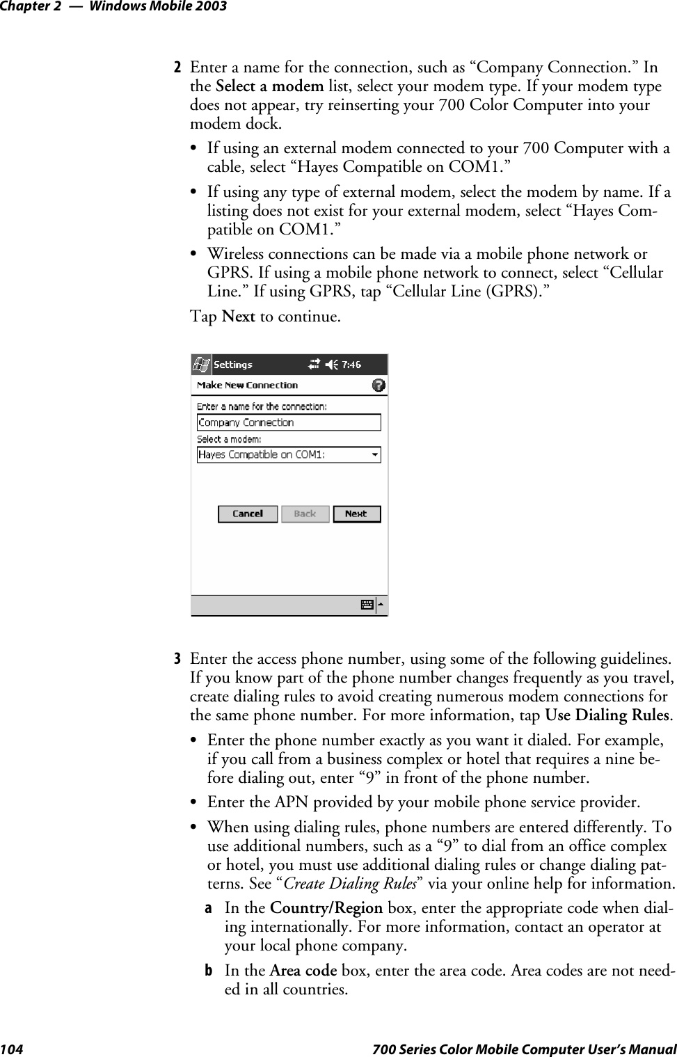
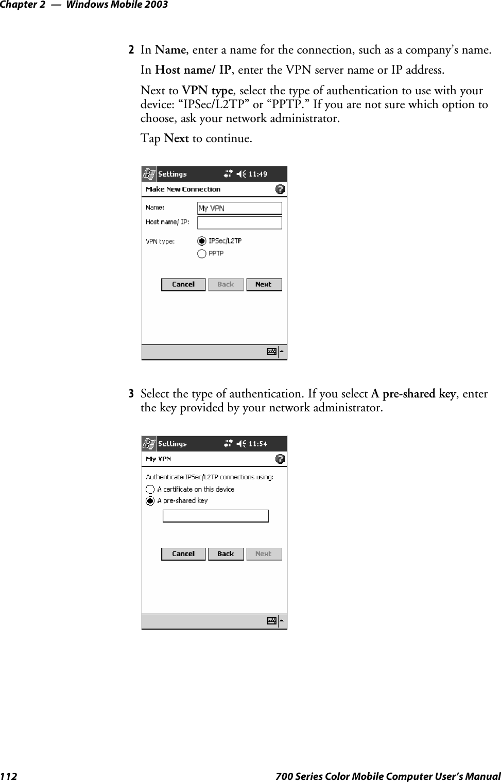
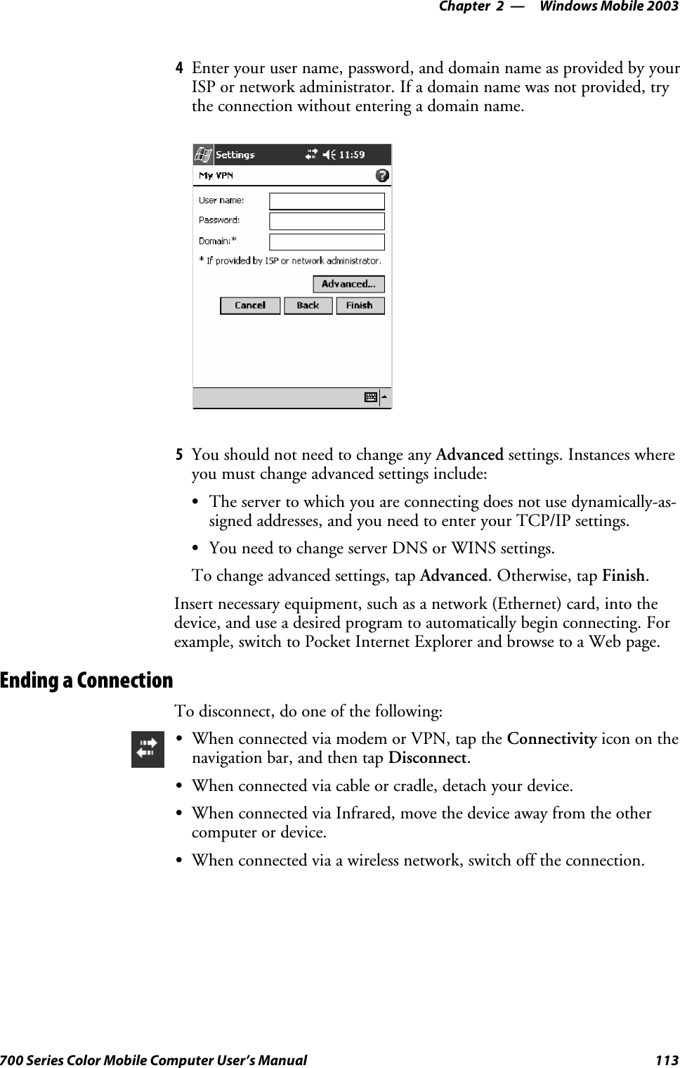
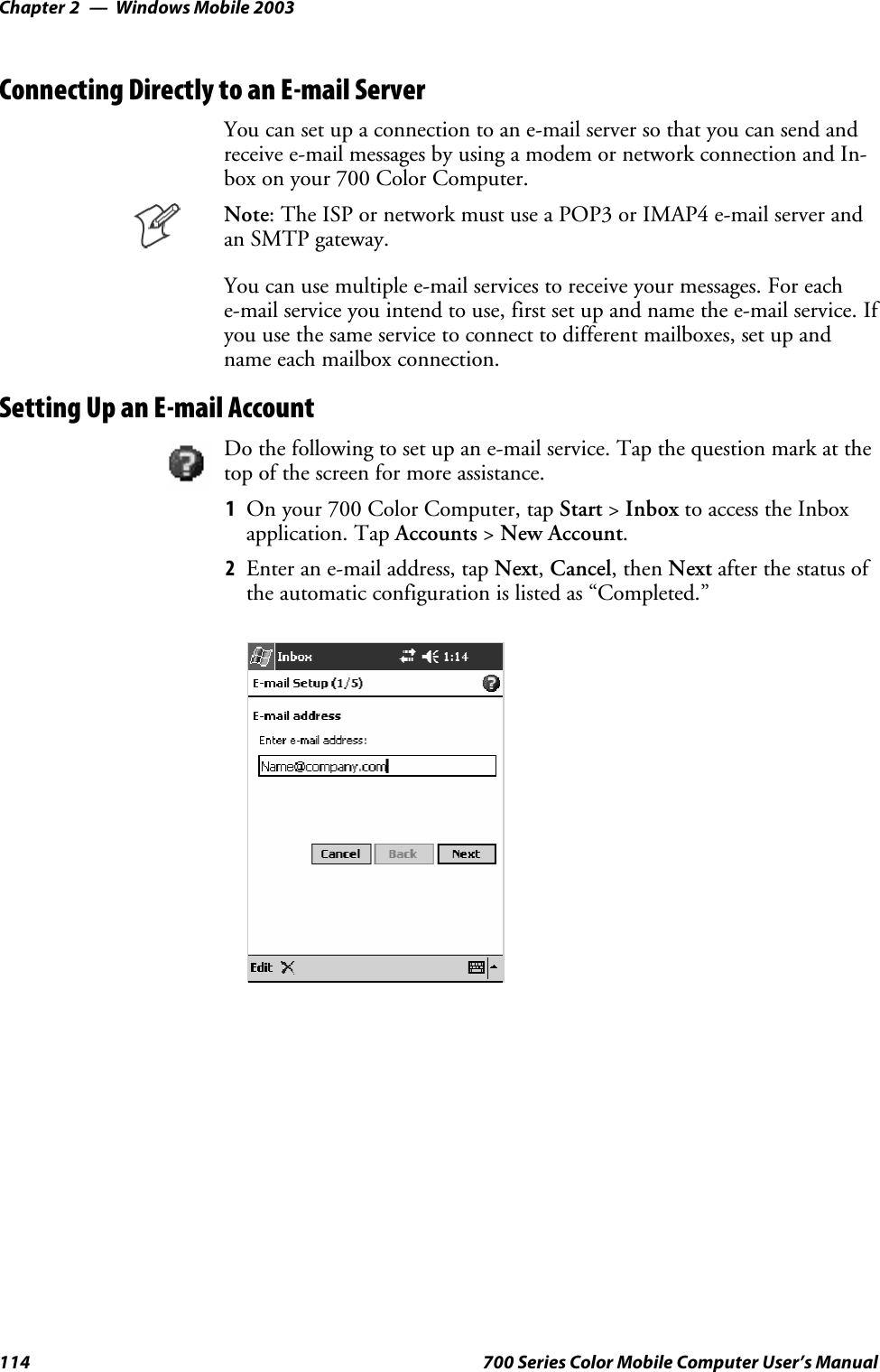
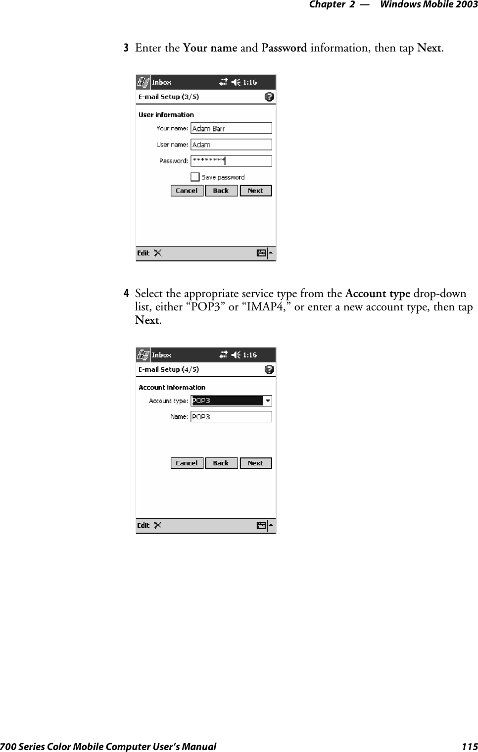
UserManual.wiki
>
Intermec Technologies
>
2610CF User Manual
>
700C User Manual 1 of 3
Contents
1.
700C User Manual 1 of 3
2.
700C User Manual 2 of 3
3.
700C User Manual 3 of 3
4.
CN2 Users Manual 1 of 2
5.
CN2 Users Manual 2 of 2
6.
Compliance Statement Insert
7.
Users Manual
8.
User Manual 1 of 3
9.
User Manual 2 of 3
10.
User Manual 3 of 3
11.
Compliance Insert
700C User Manual 1 of 3
Navigation menu
Upload a User Manual
Namespaces
Wiki Guide
HTML
PDF
Info
Views
User Manual
Discussion / Help
Navigation
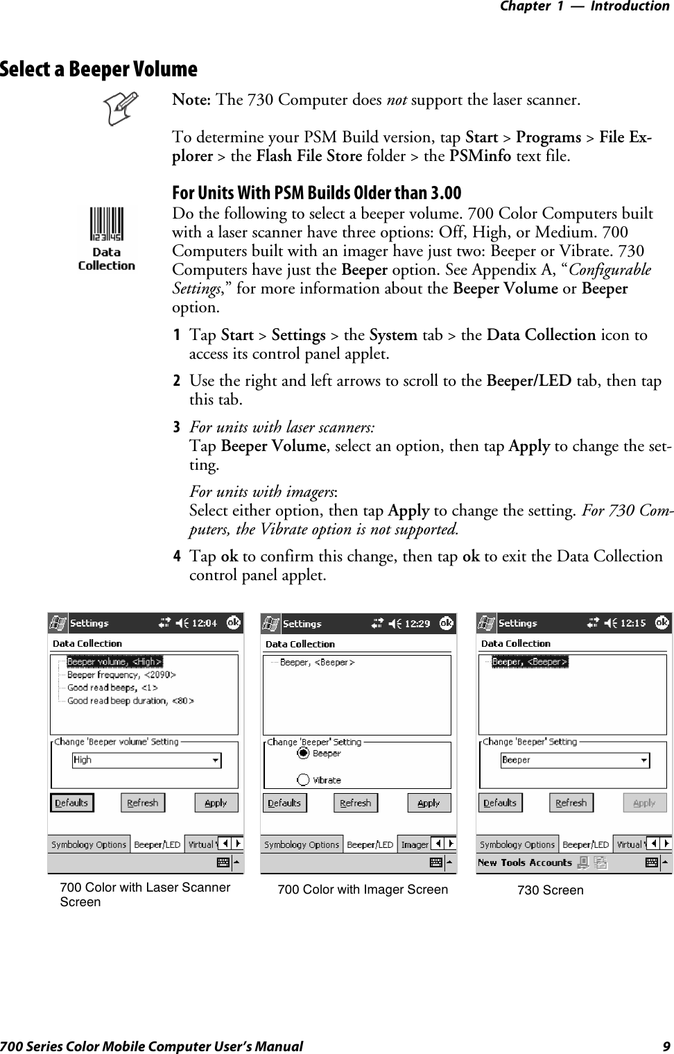
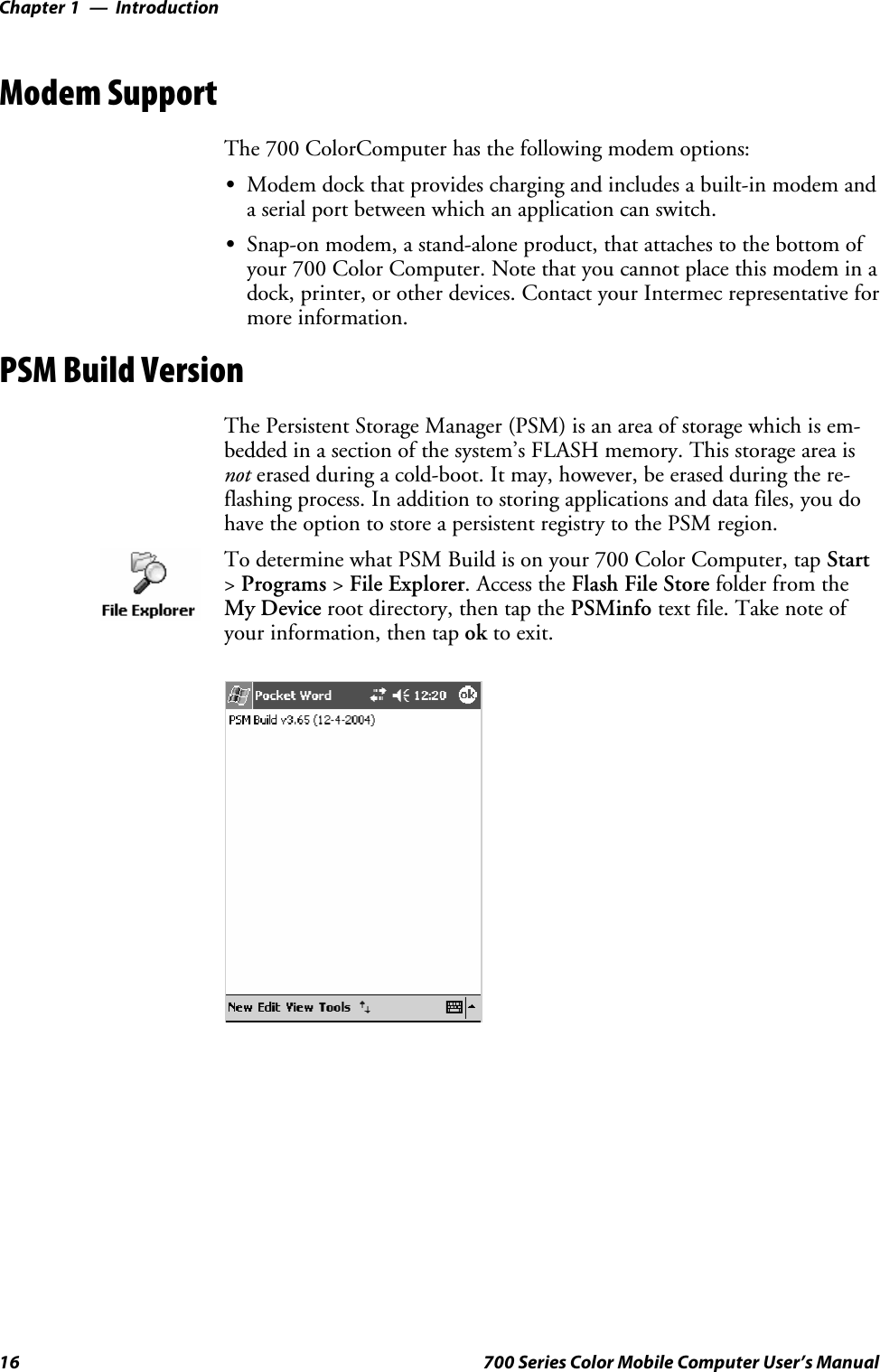
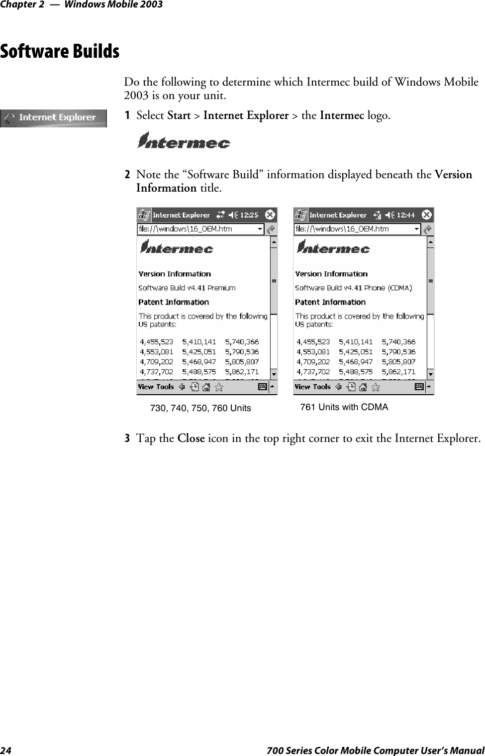
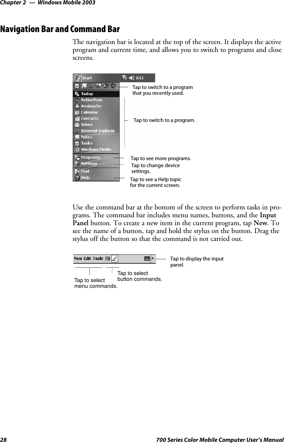
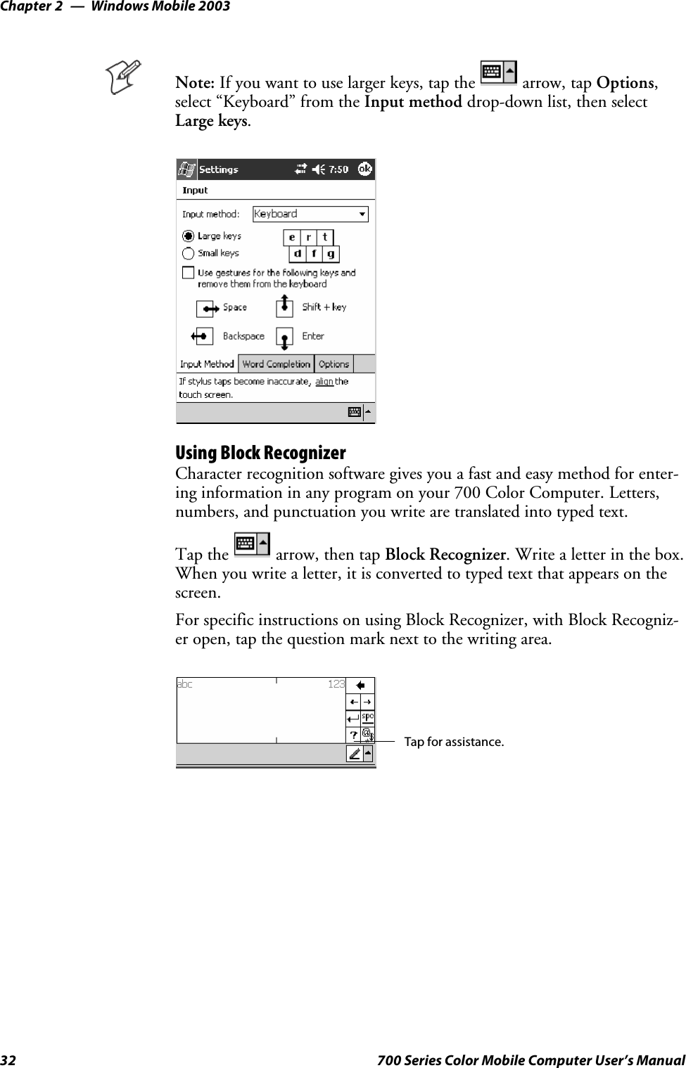
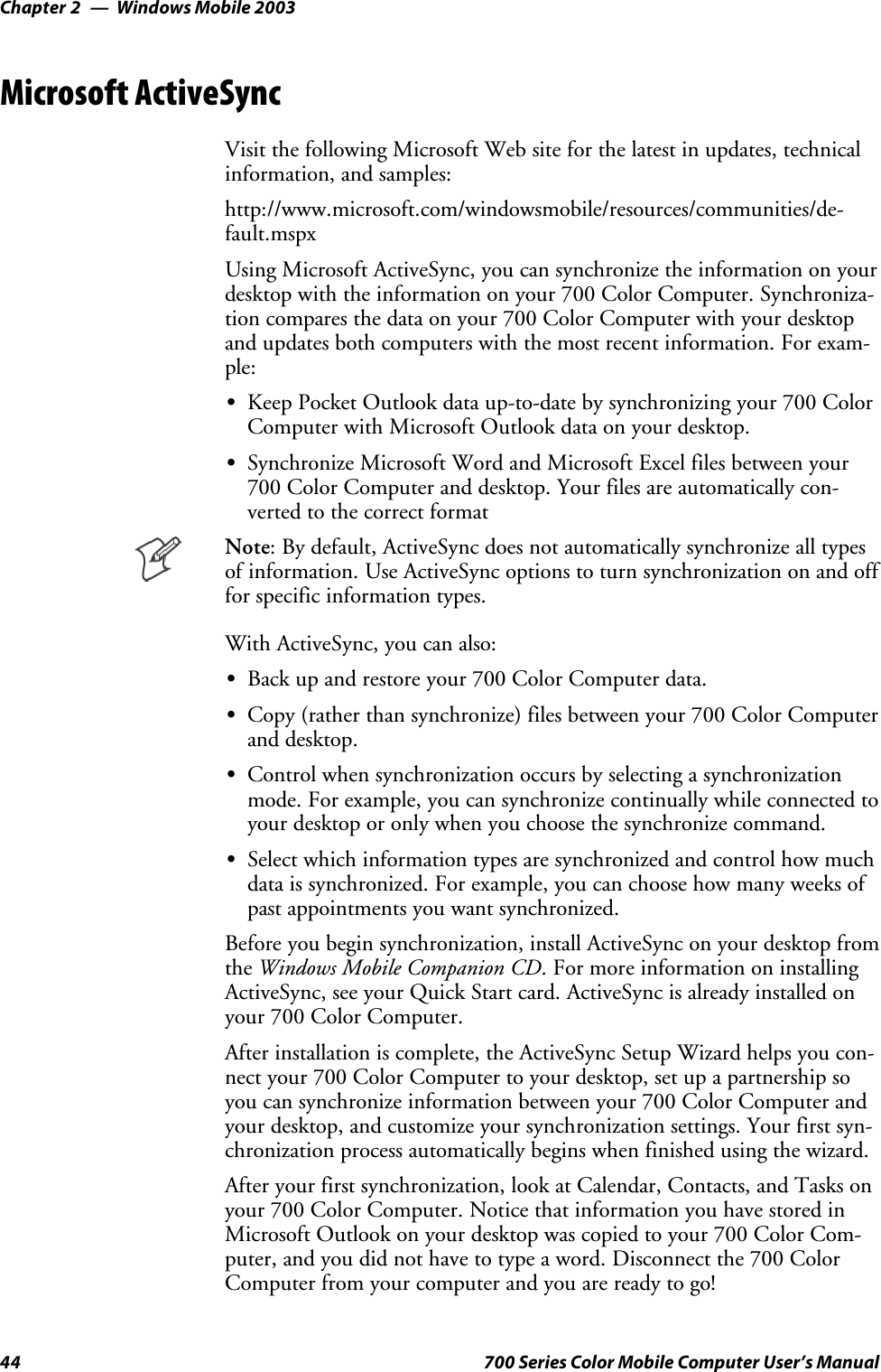
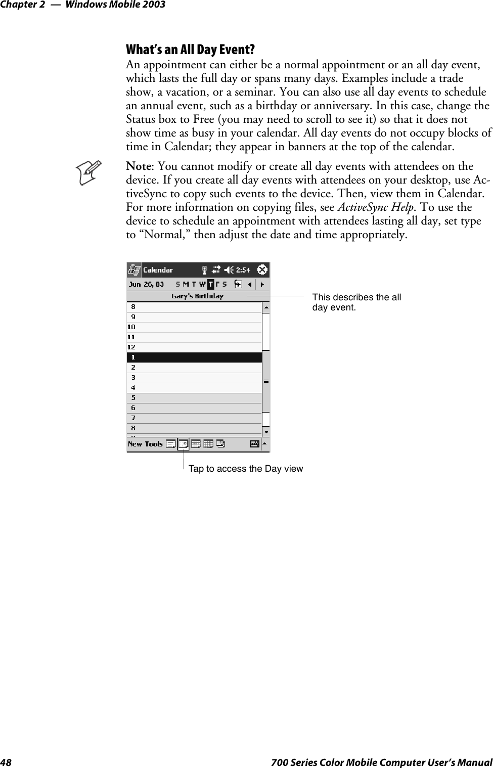
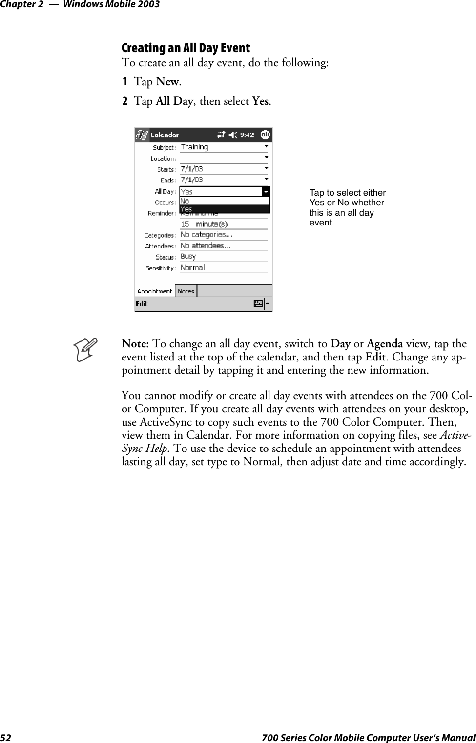
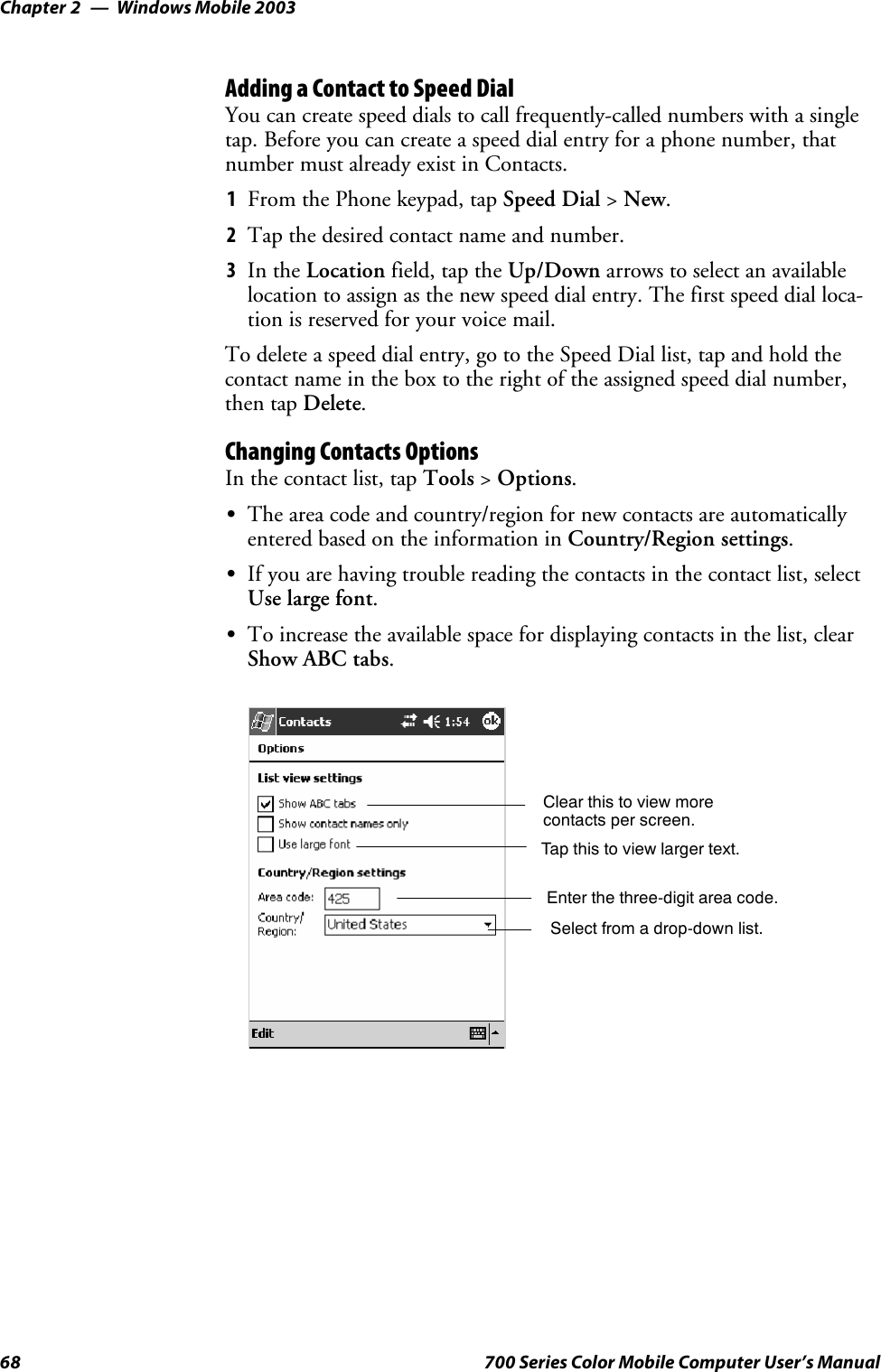
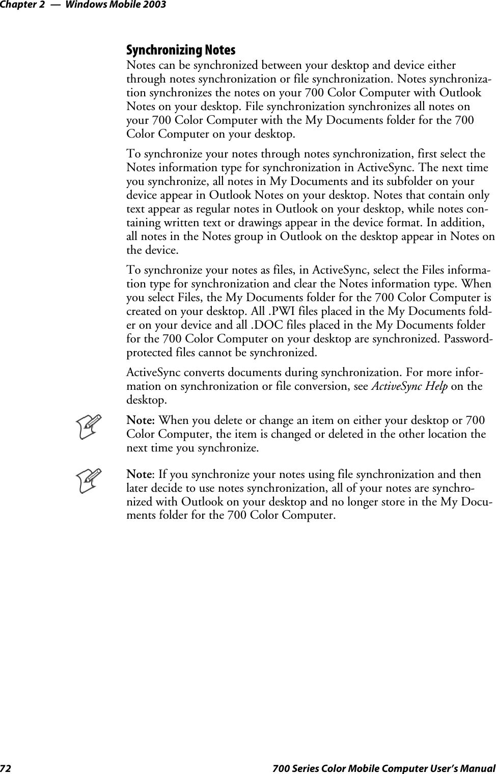
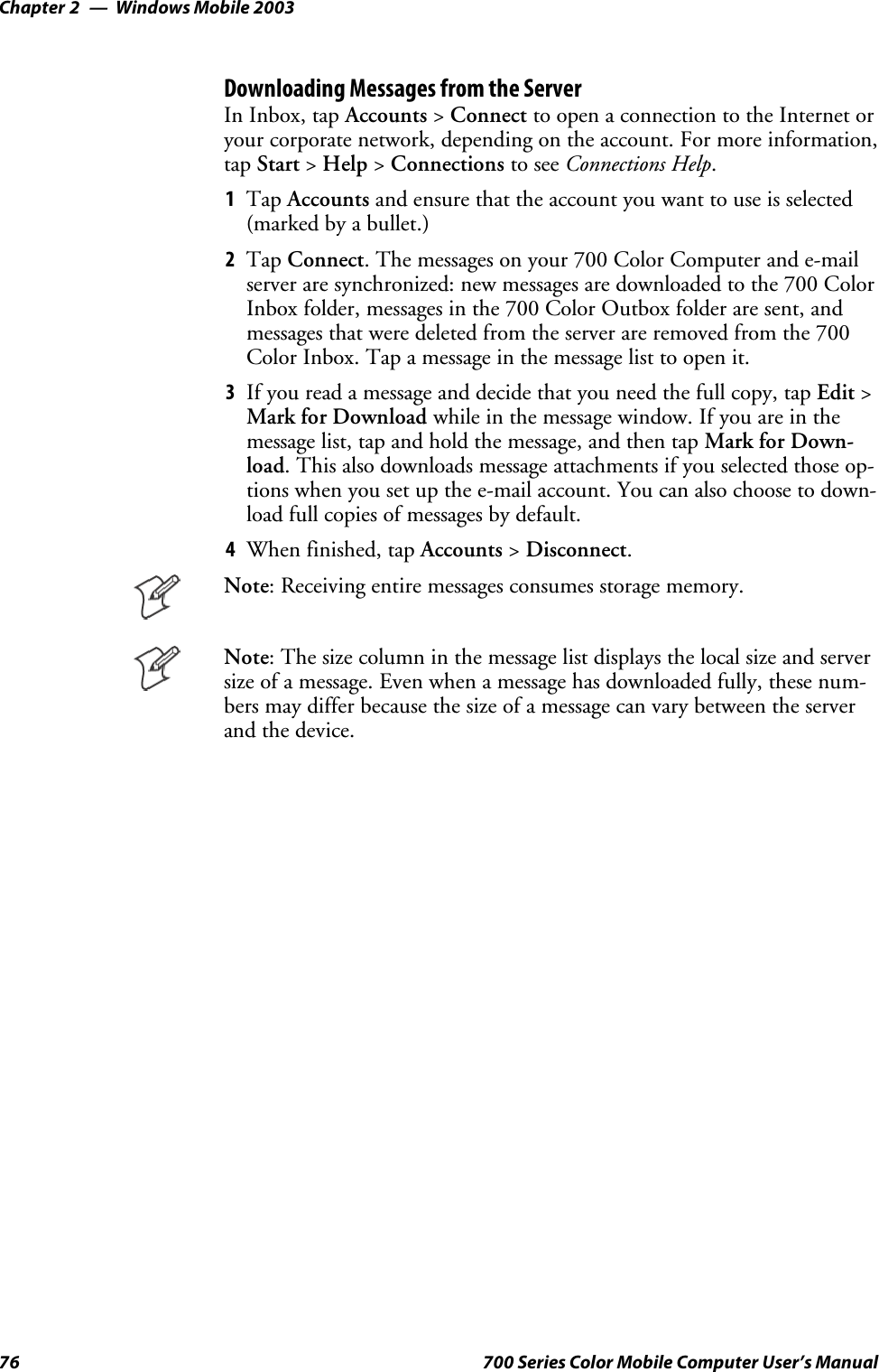
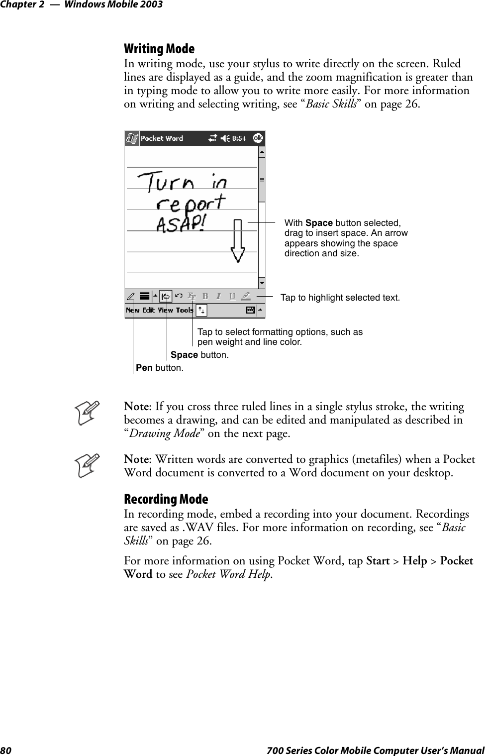
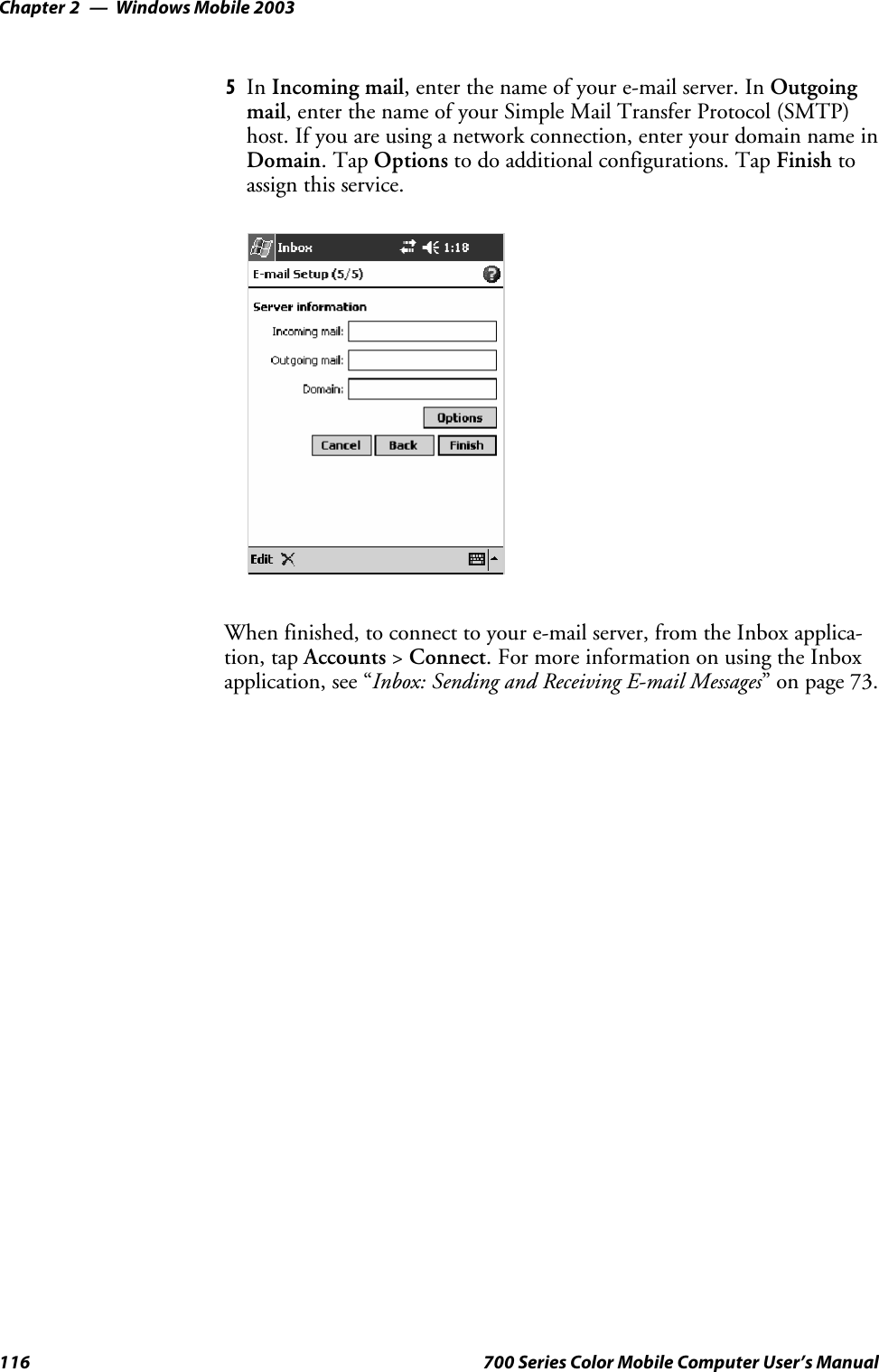
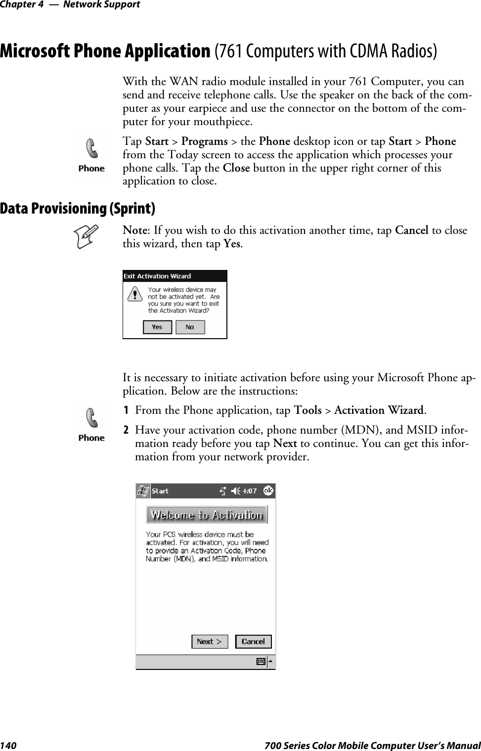
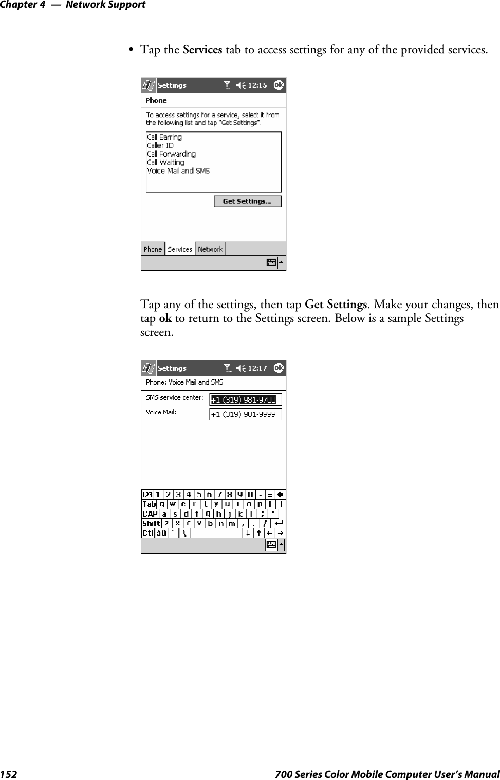
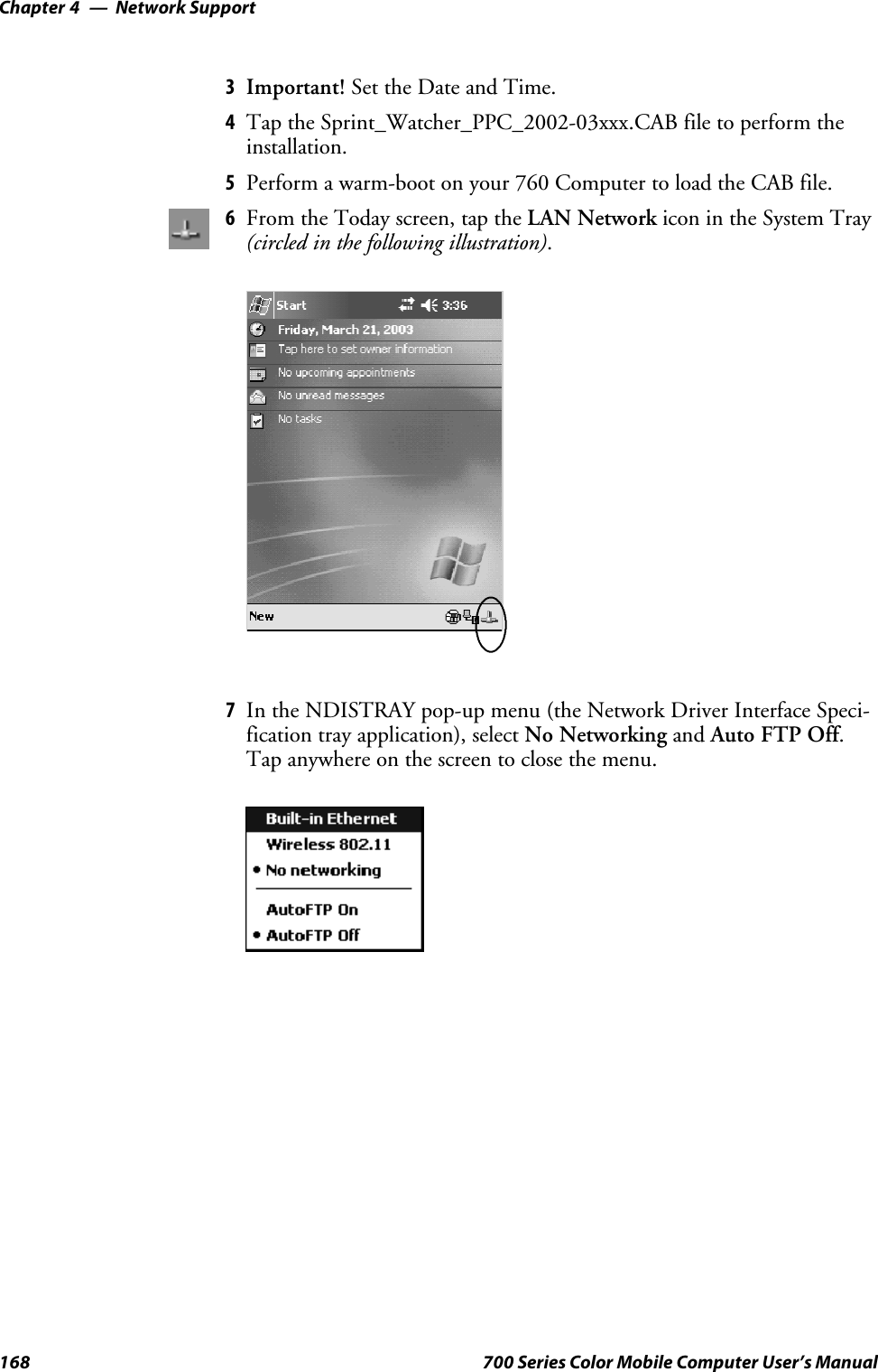
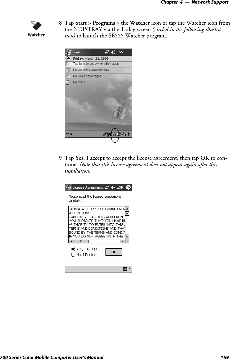
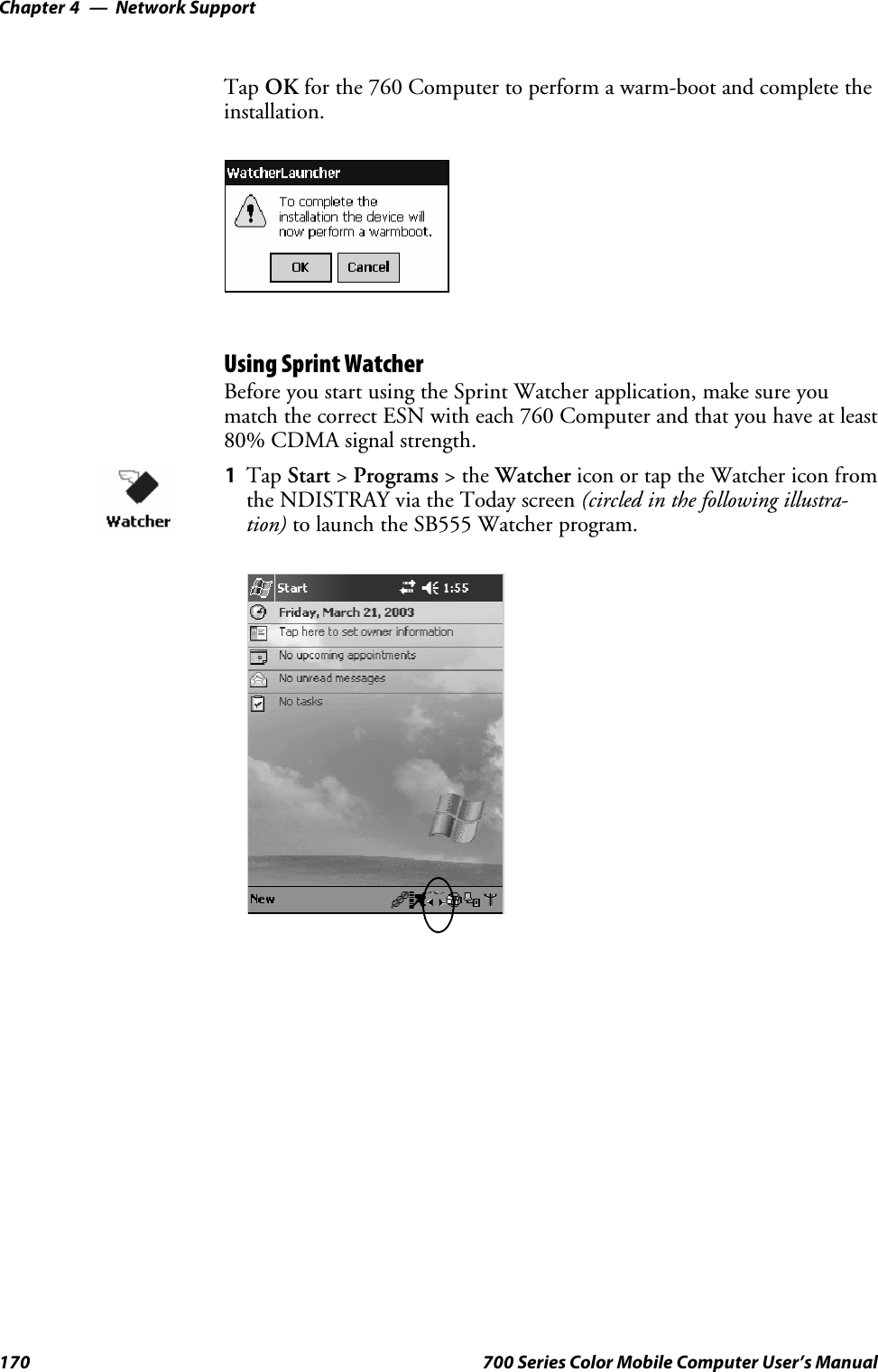
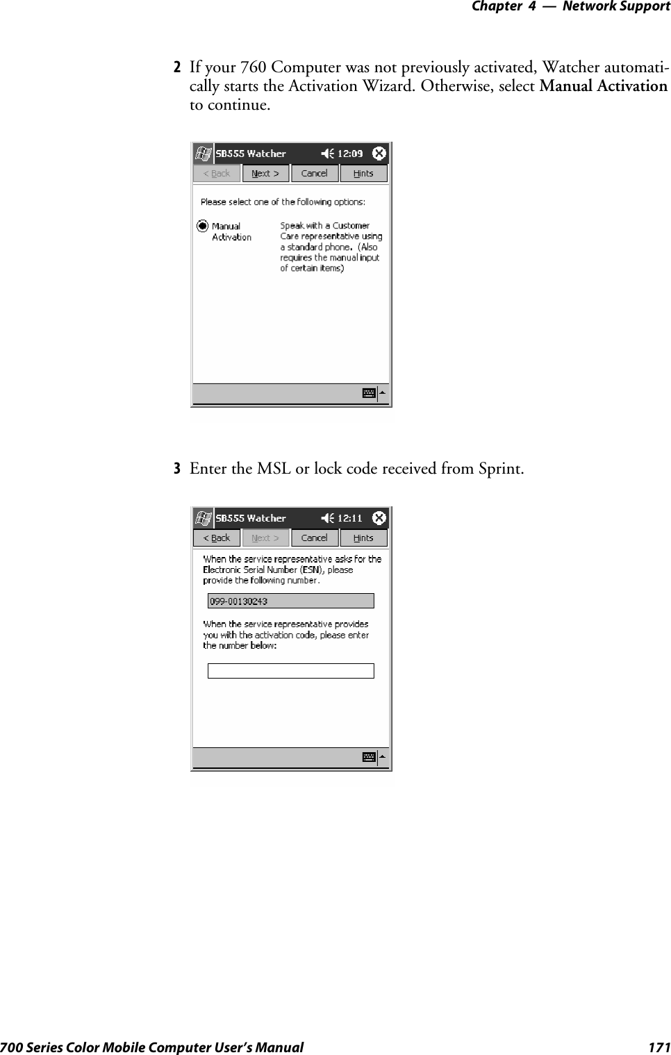
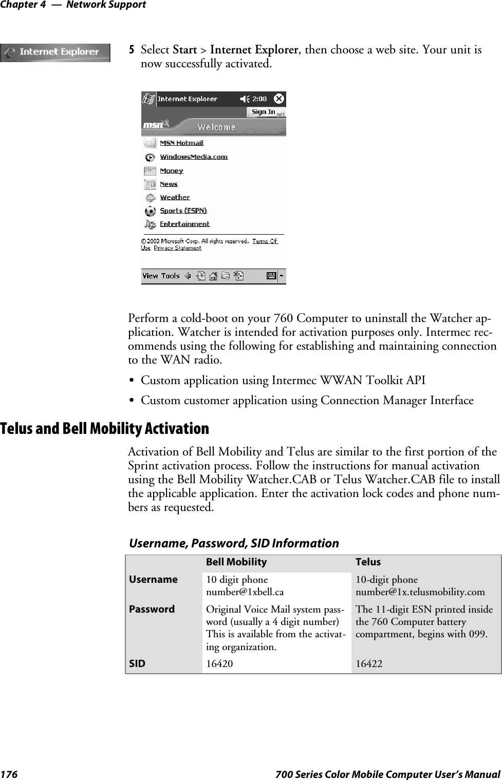
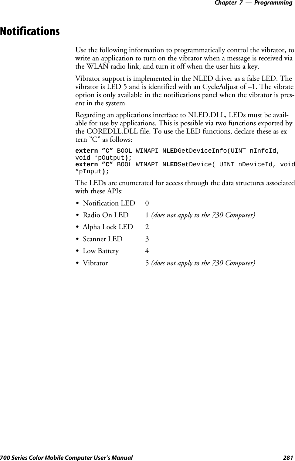
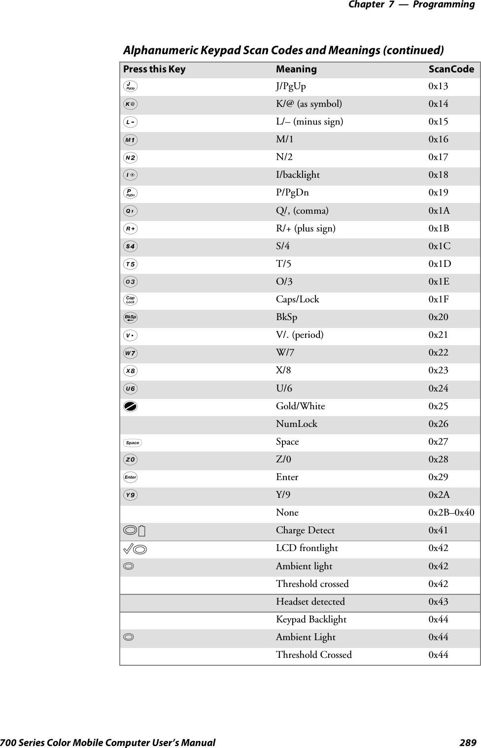
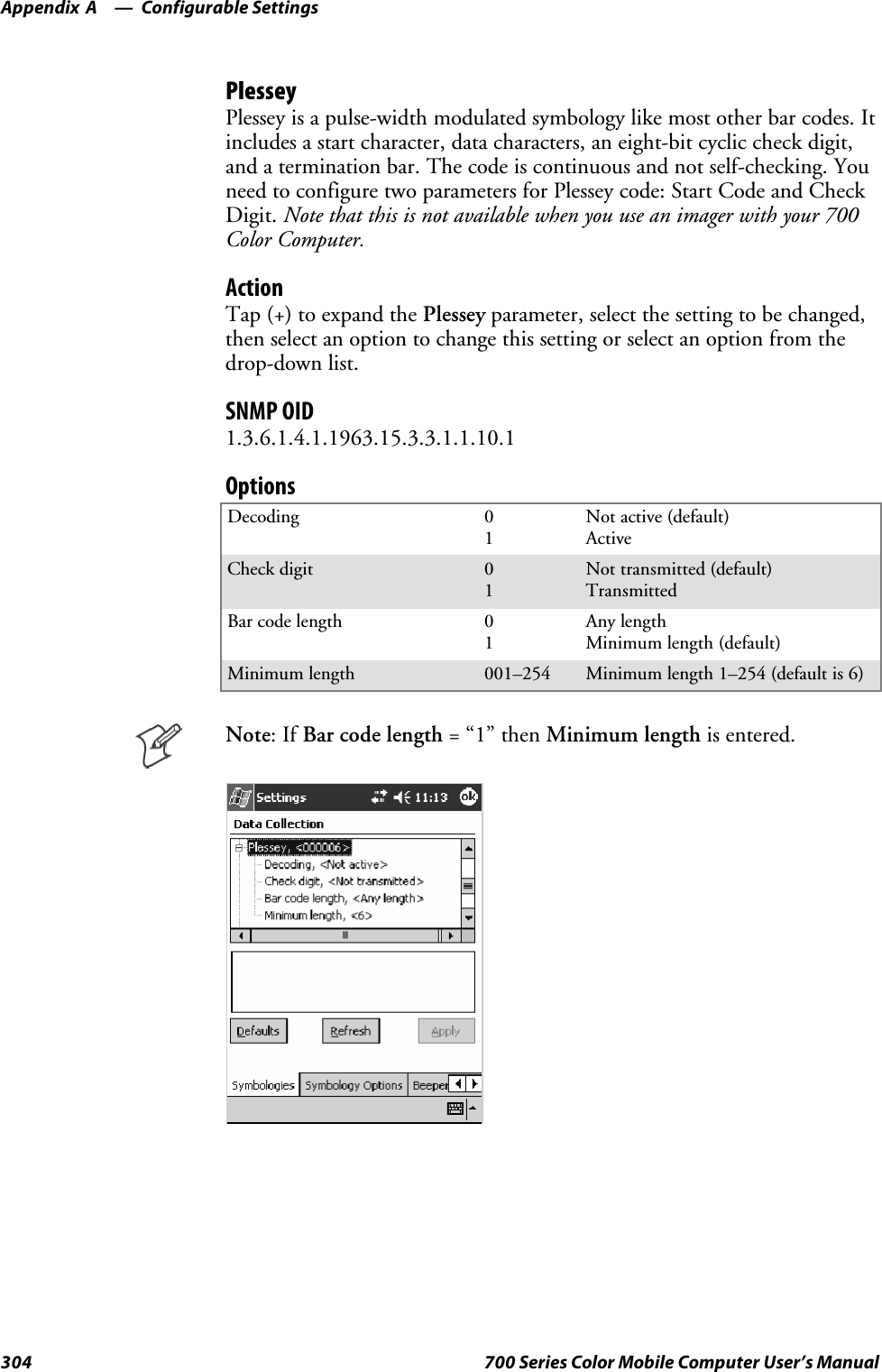
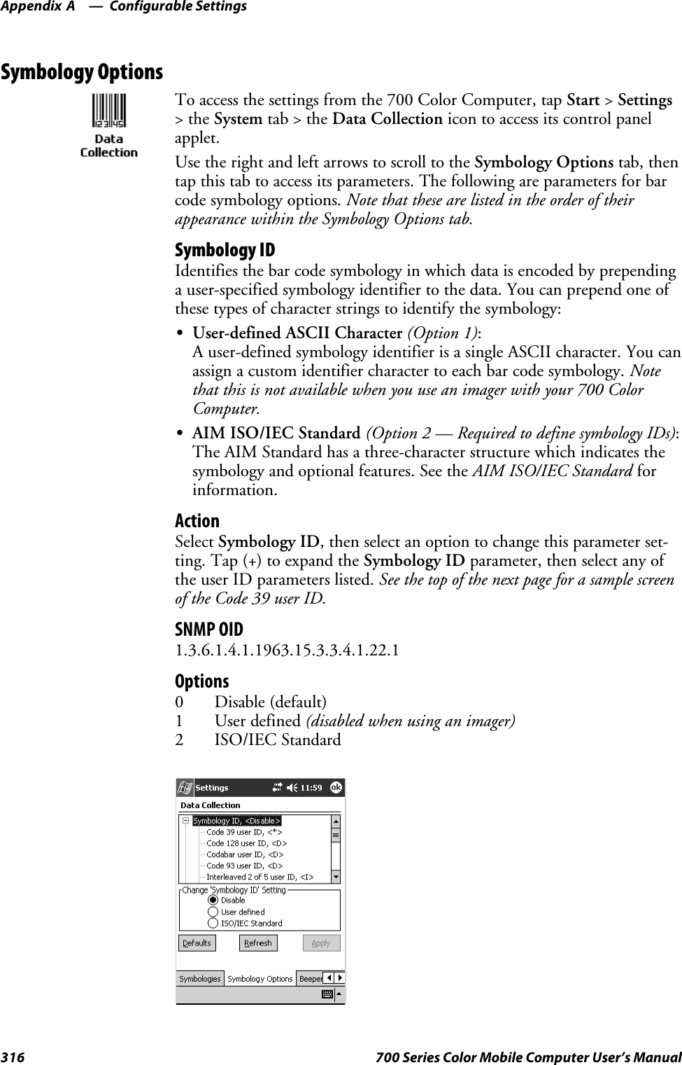
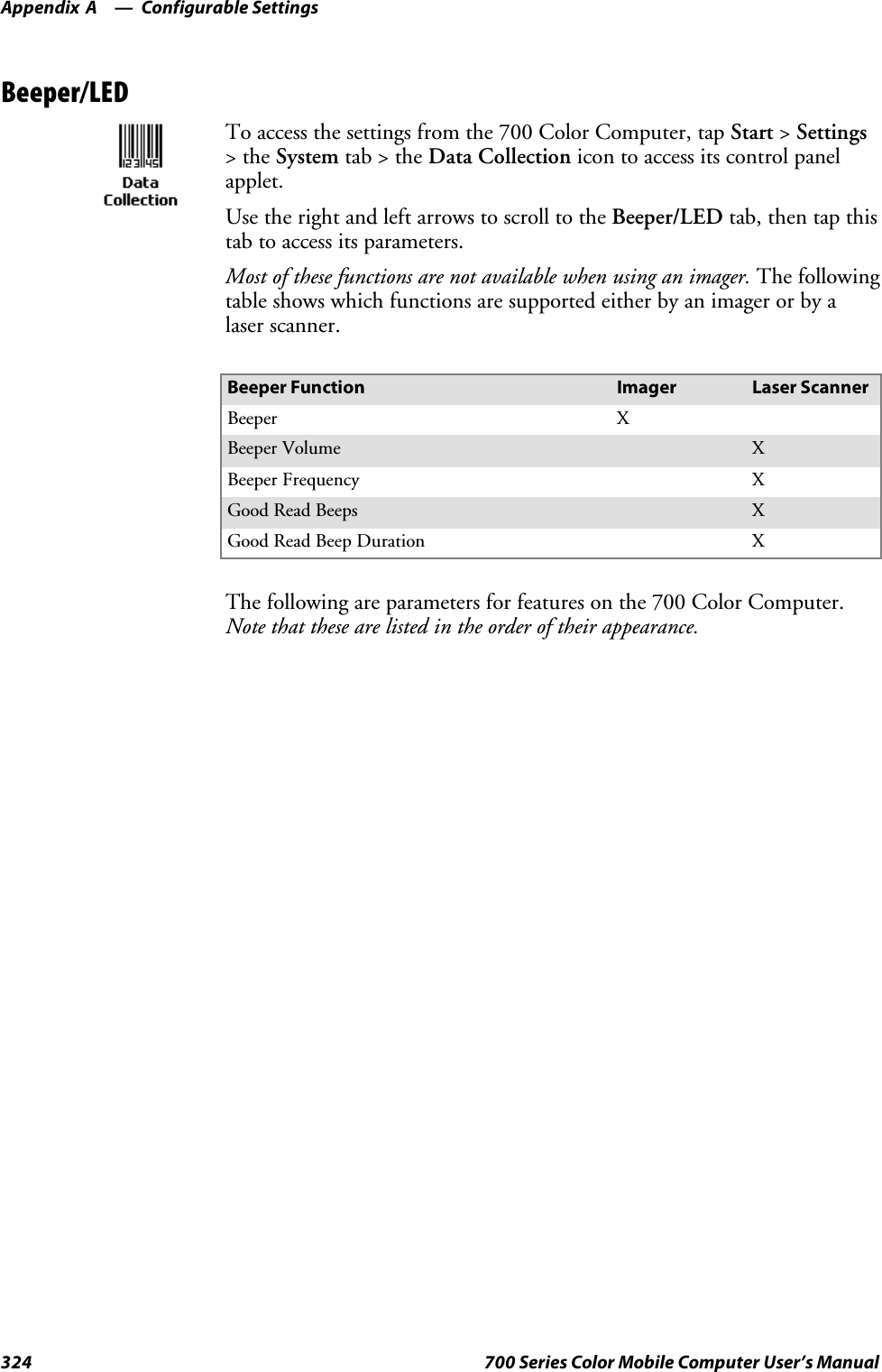
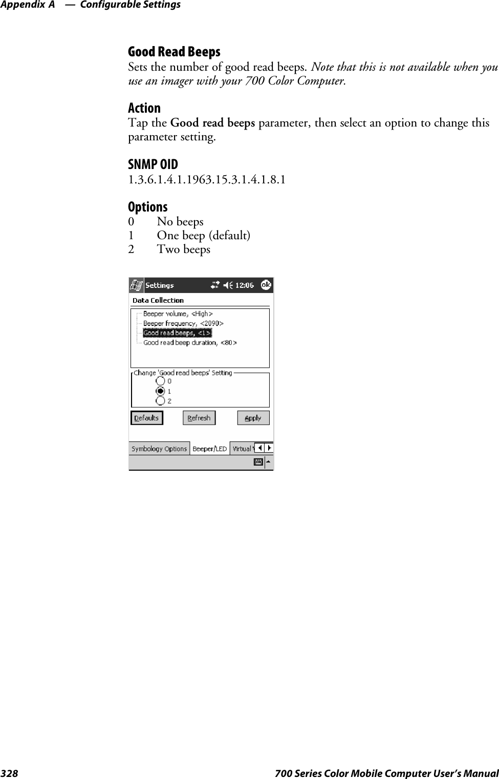
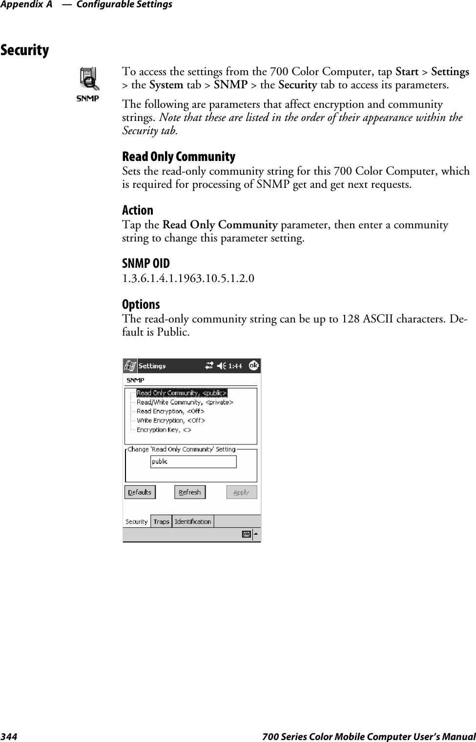
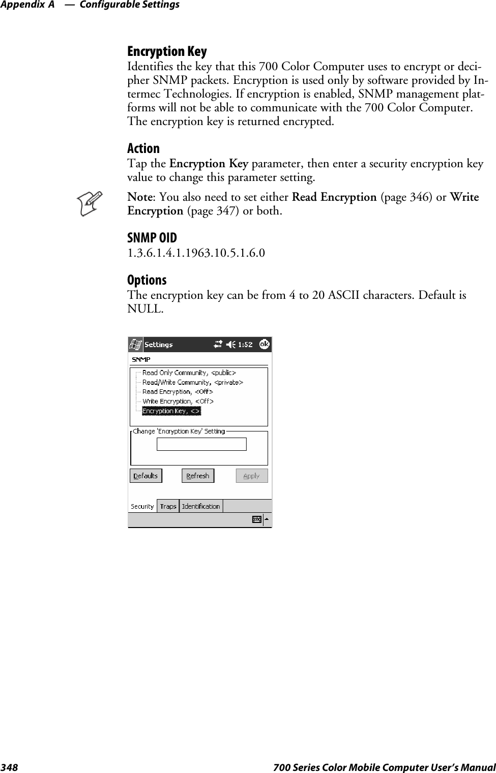
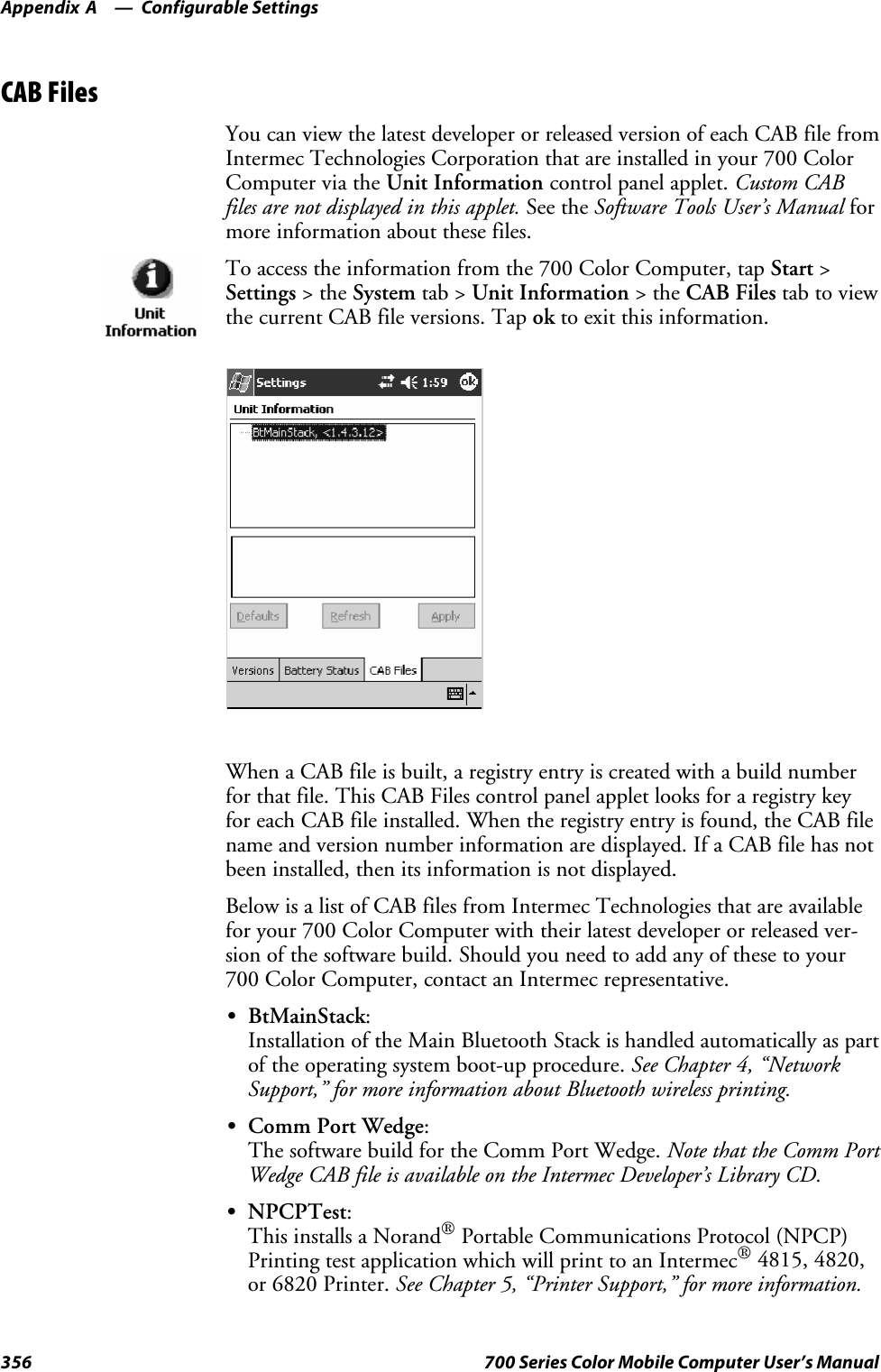
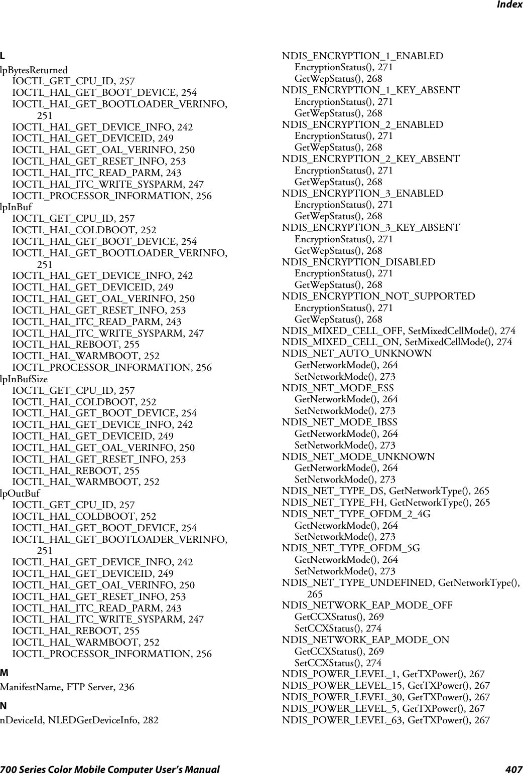
![Contentsv700 Series Color Mobile Computer User’s ManualContentsBefore You Begin xix.............................................................Safety Summary xix.......................................................Donotrepairoradjustalone xix.......................................First aid xix.......................................................Resuscitation xix...................................................Energized equipment xix.............................................Safety Icons xx...........................................................Global Services and Support xxi..............................................Warranty Information xxi............................................Web Support xxi...................................................Telephone Support xxi...............................................WhoShouldReadthisManual? xxii..........................................Related Documents xxii....................................................Introduction1...............................................................Ambient Light Sensor 2..........................................................Audio System 3.................................................................Speaker 3...............................................................Microphone 4...........................................................External Headset Jack 4....................................................Battery 5......................................................................Beeper 7......................................................................Enable the Beeper 7.......................................................Disable the Scanner Mute 8.................................................Select a Beeper Volume 9...................................................Disable the Beeper 10.....................................................Keypad 11.....................................................................Backlight for Keypad 11....................................................Key Sequences 12.........................................................[Gold] or [Gold/White] Plane Keys 12..................................Alpha (Blue) Plane Keys 14...........................................Modem Support 16..............................................................PSM Build Version 16...........................................................Resetting Your 700 Color Computer 17..............................................Software Build Version 18.........................................................1](https://usermanual.wiki/Intermec-Technologies/2610CF.700C-User-Manual-1-of-3/User-Guide-527885-Page-5.png)
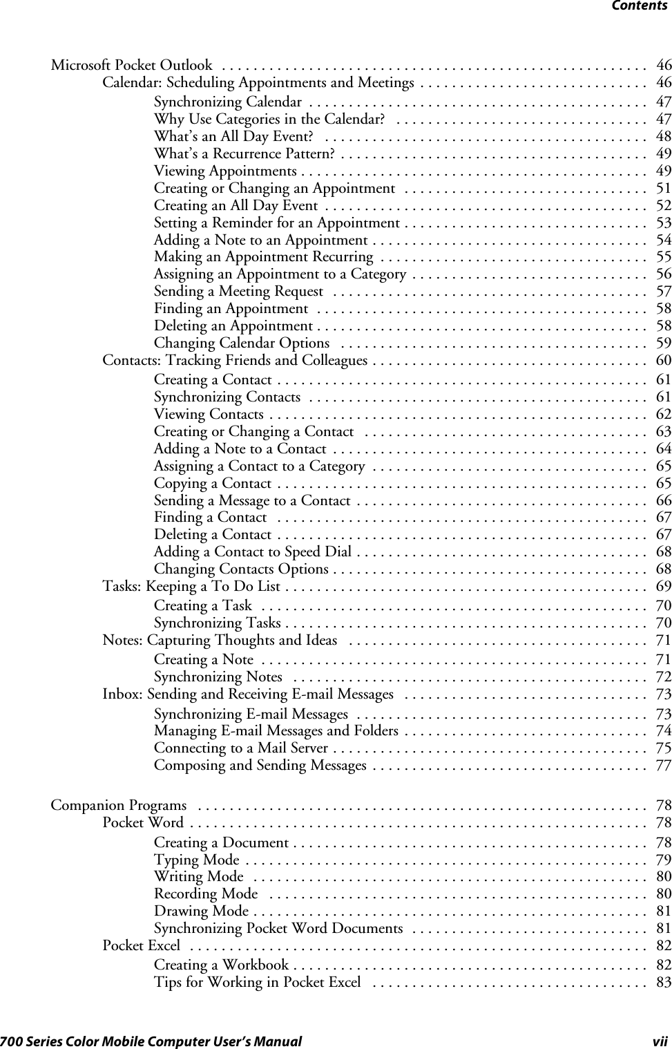
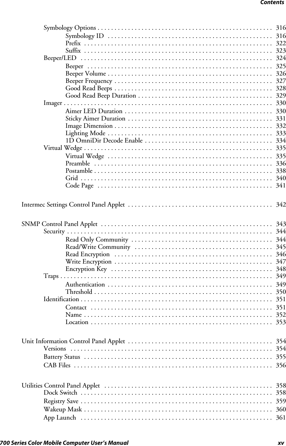

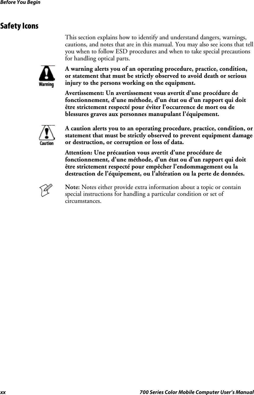
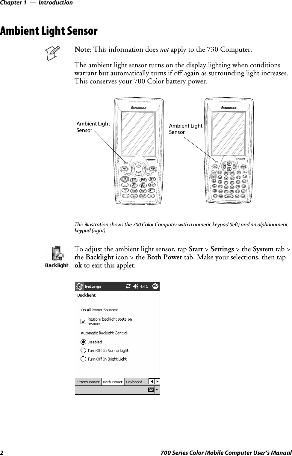
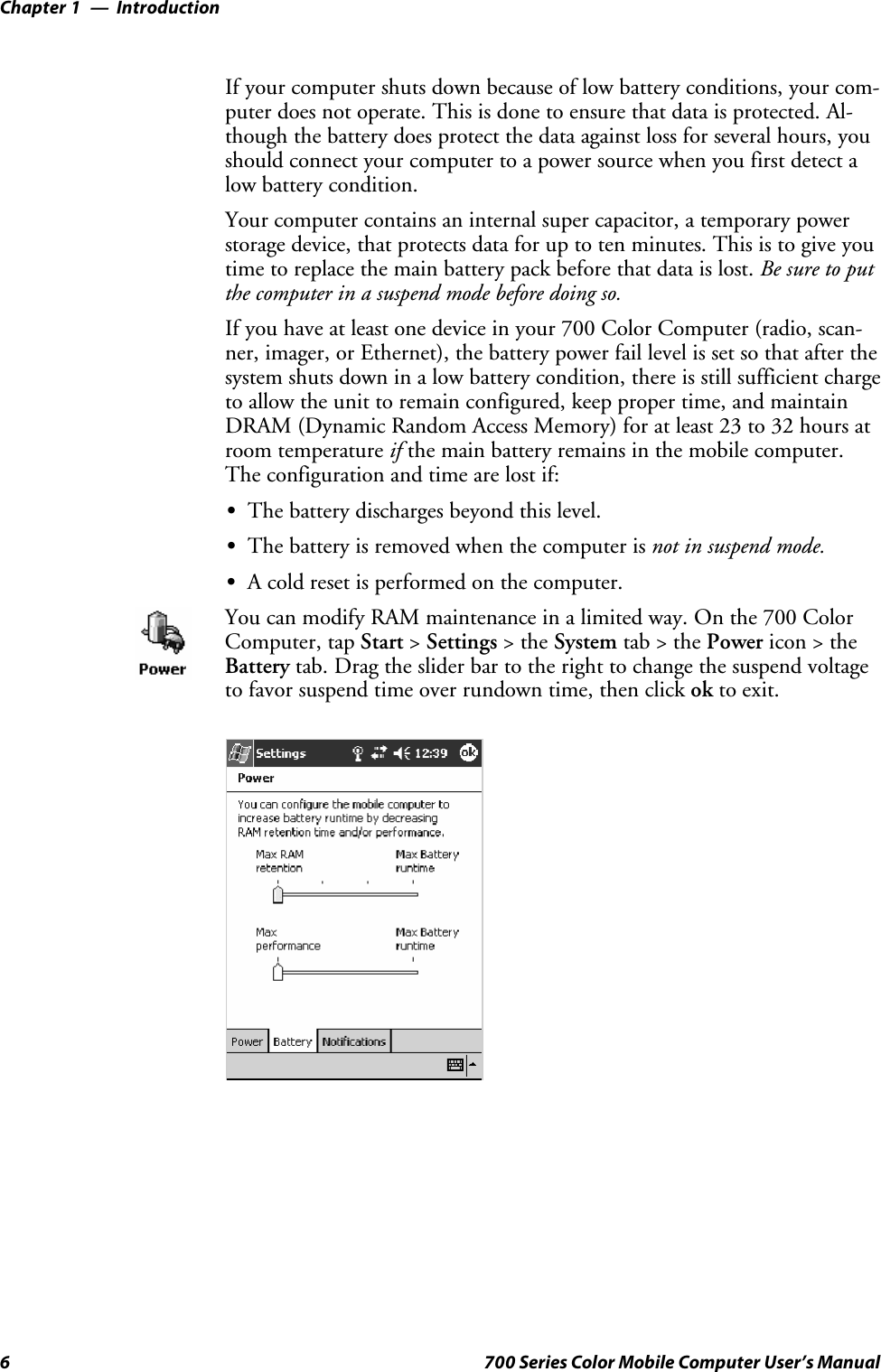
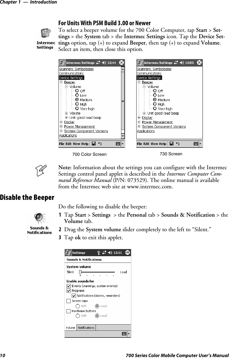
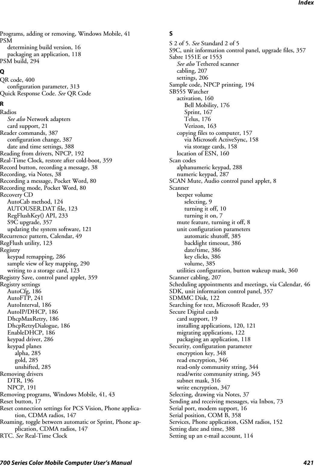
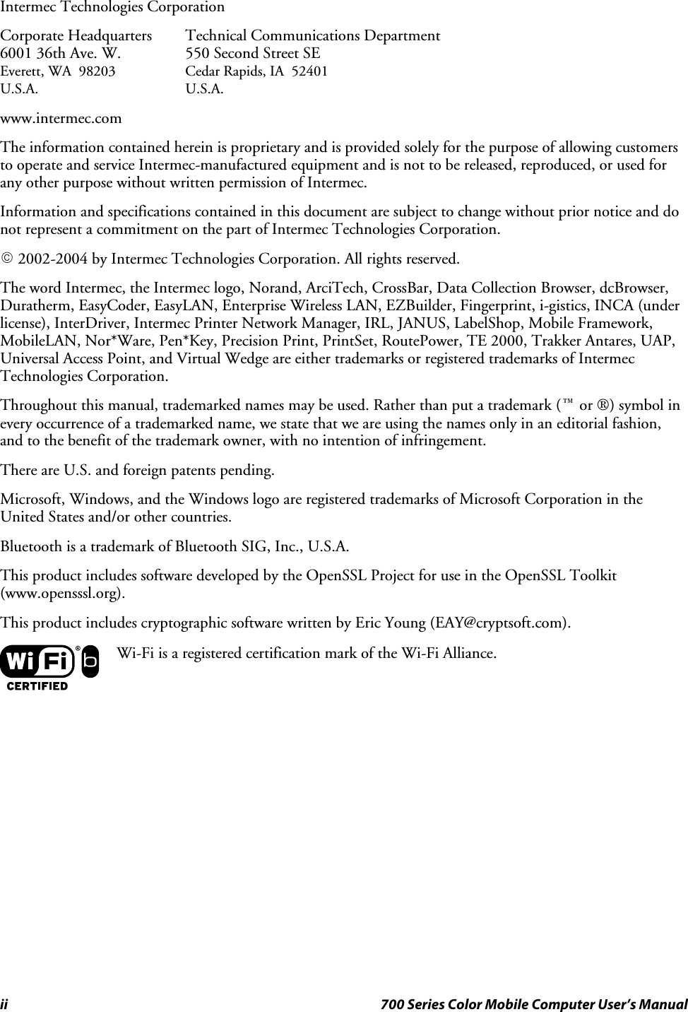
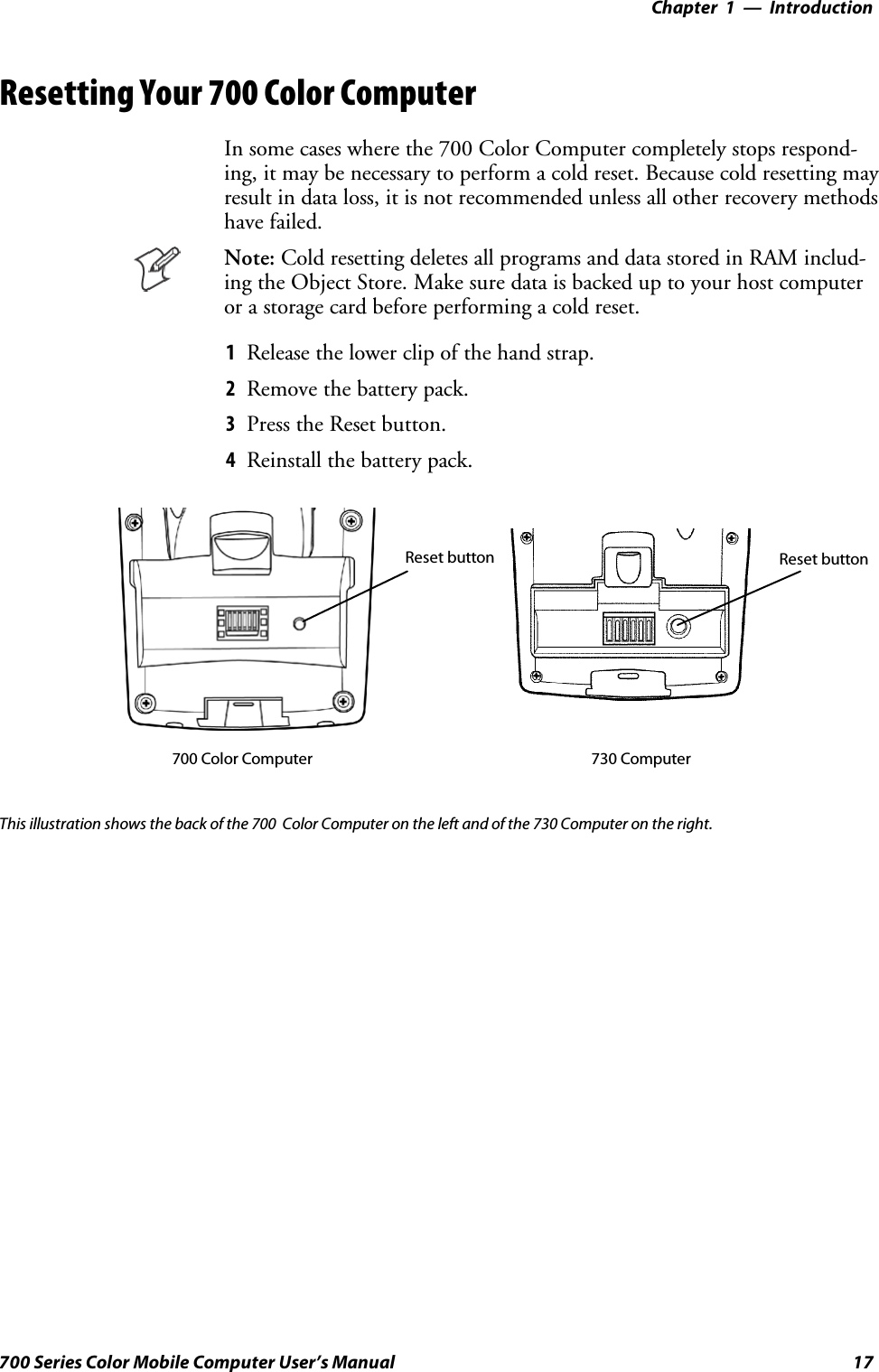
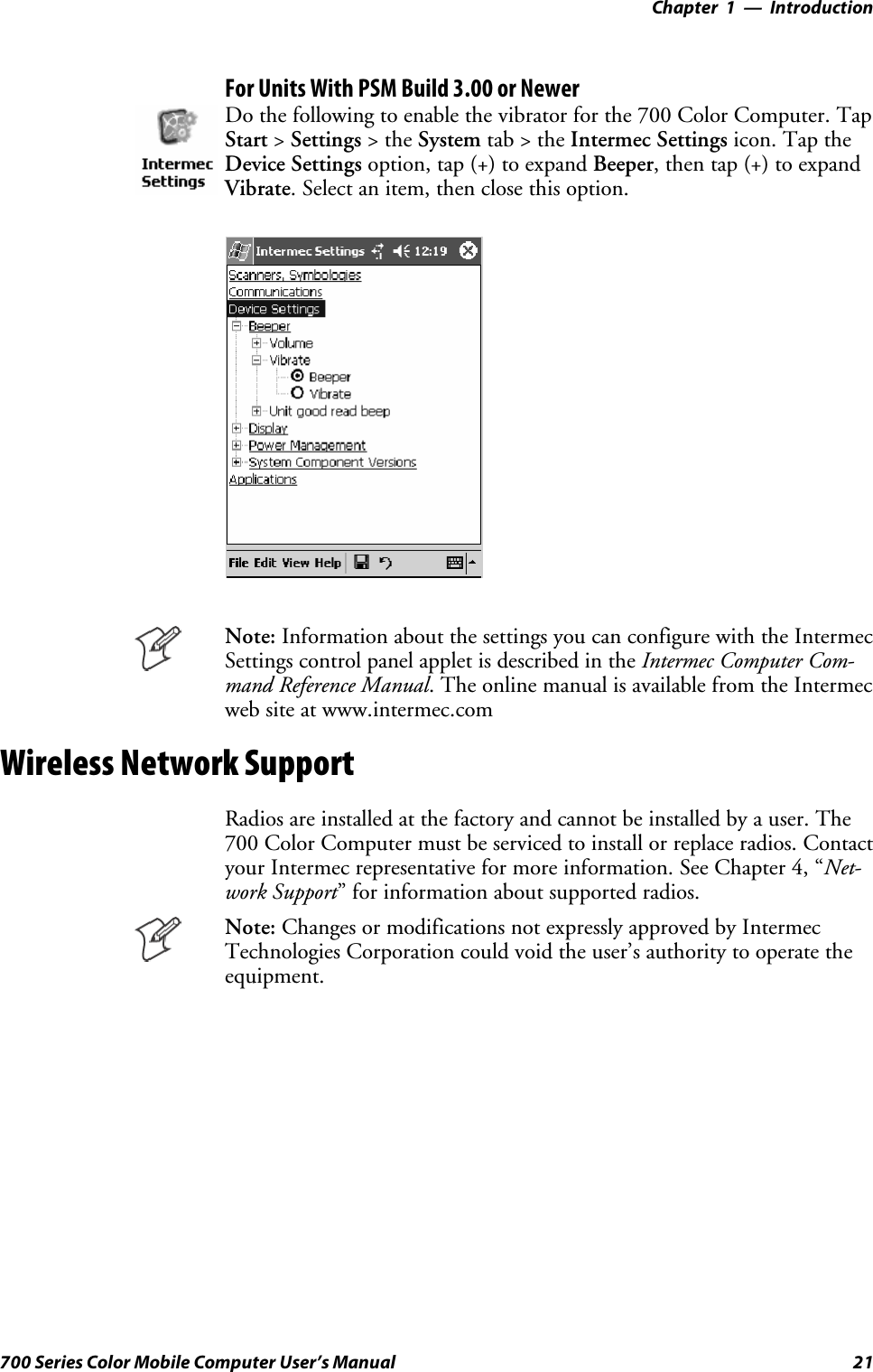
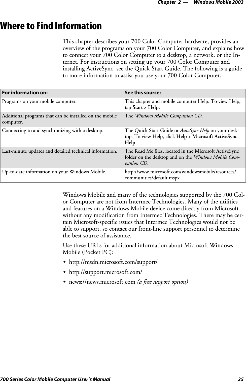
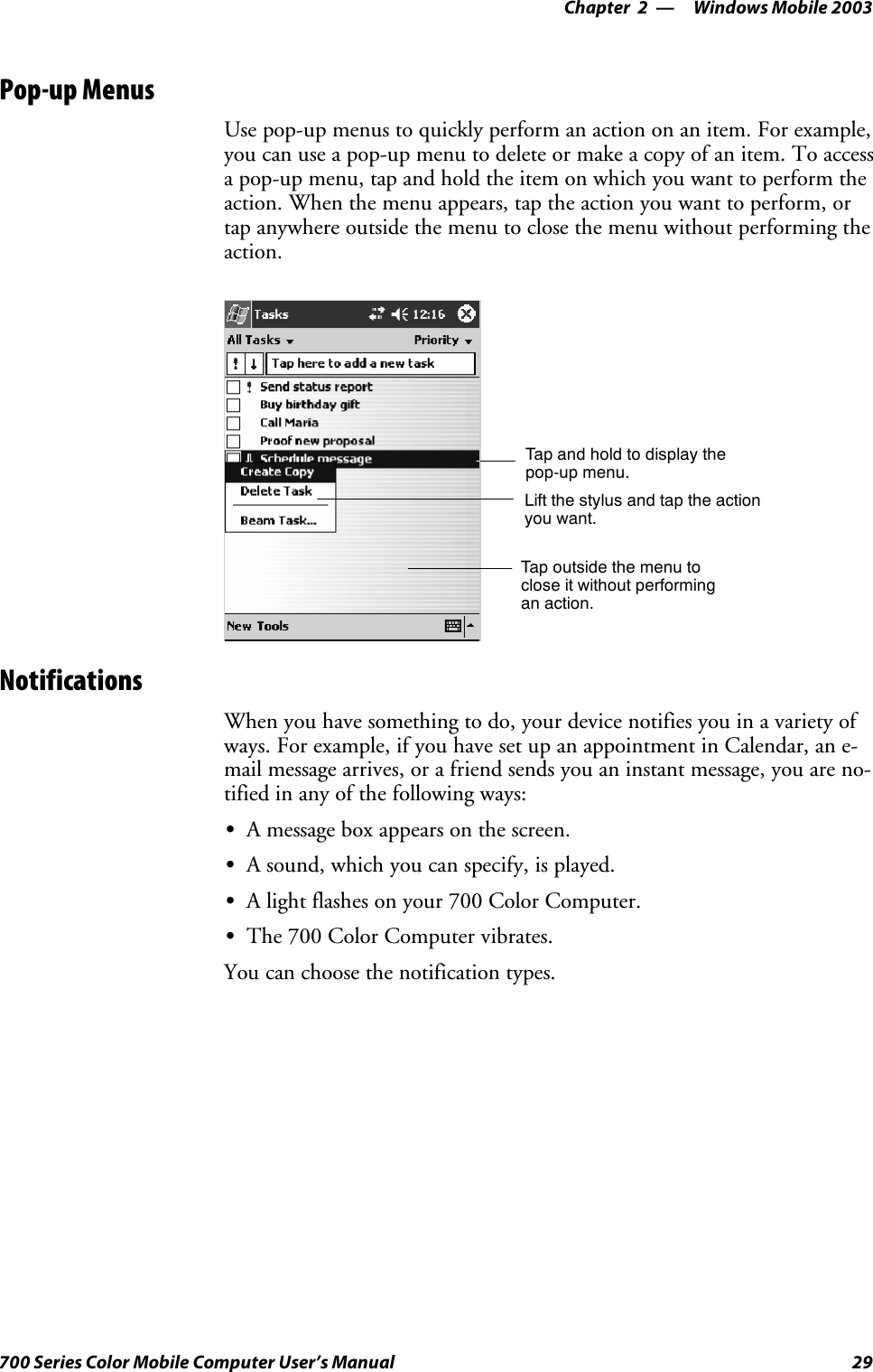
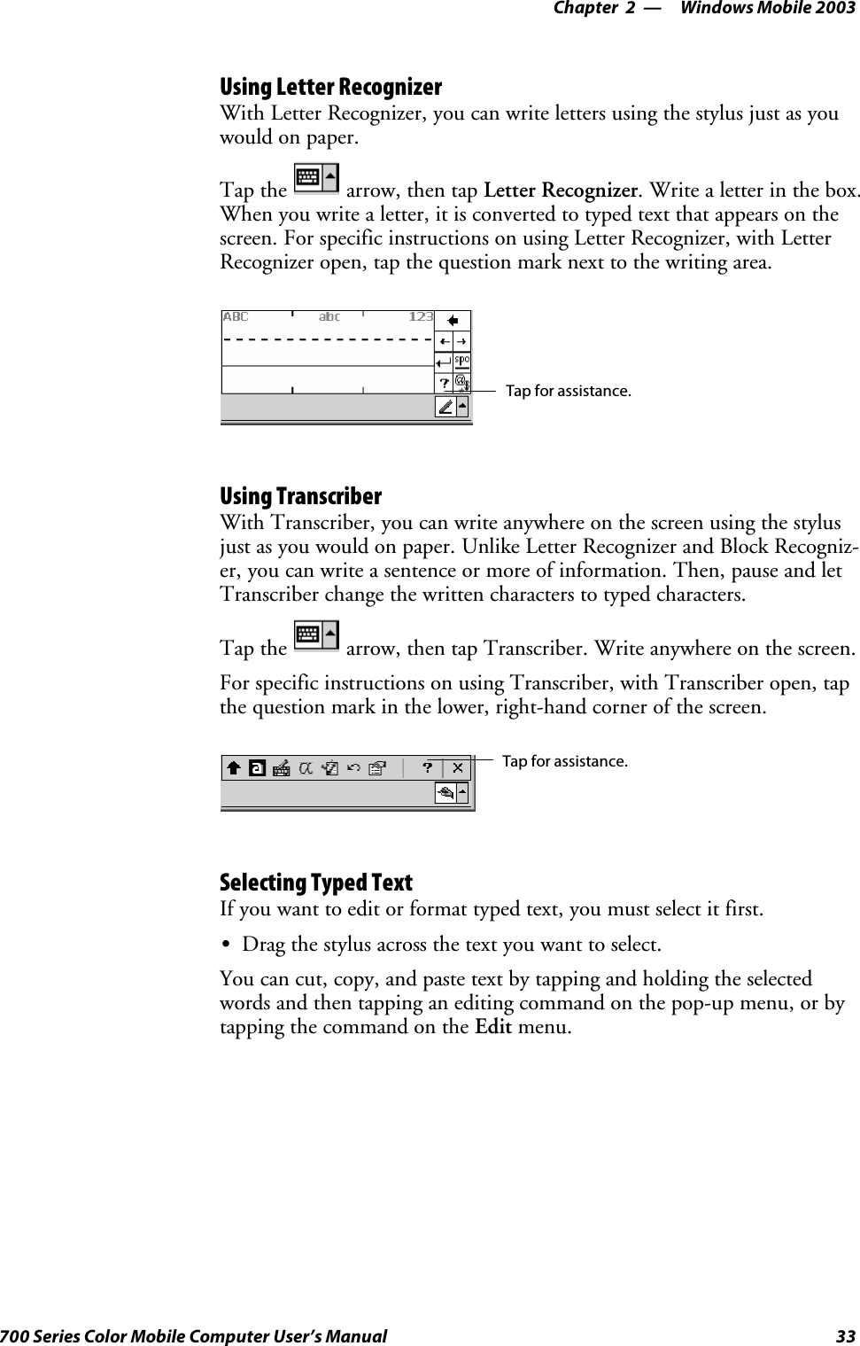
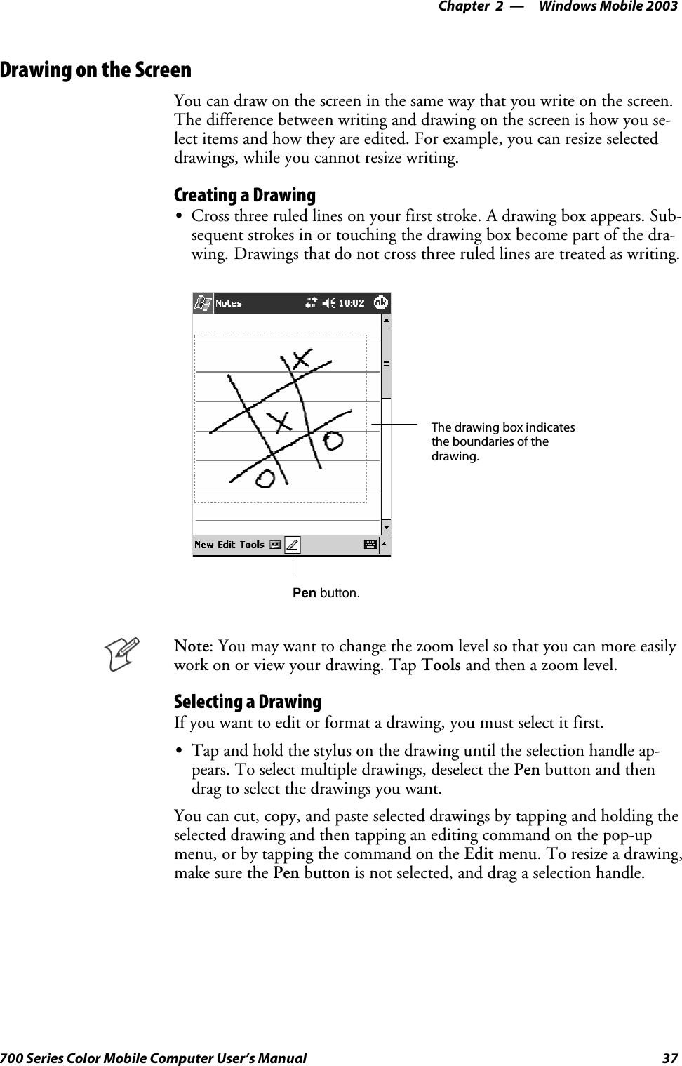
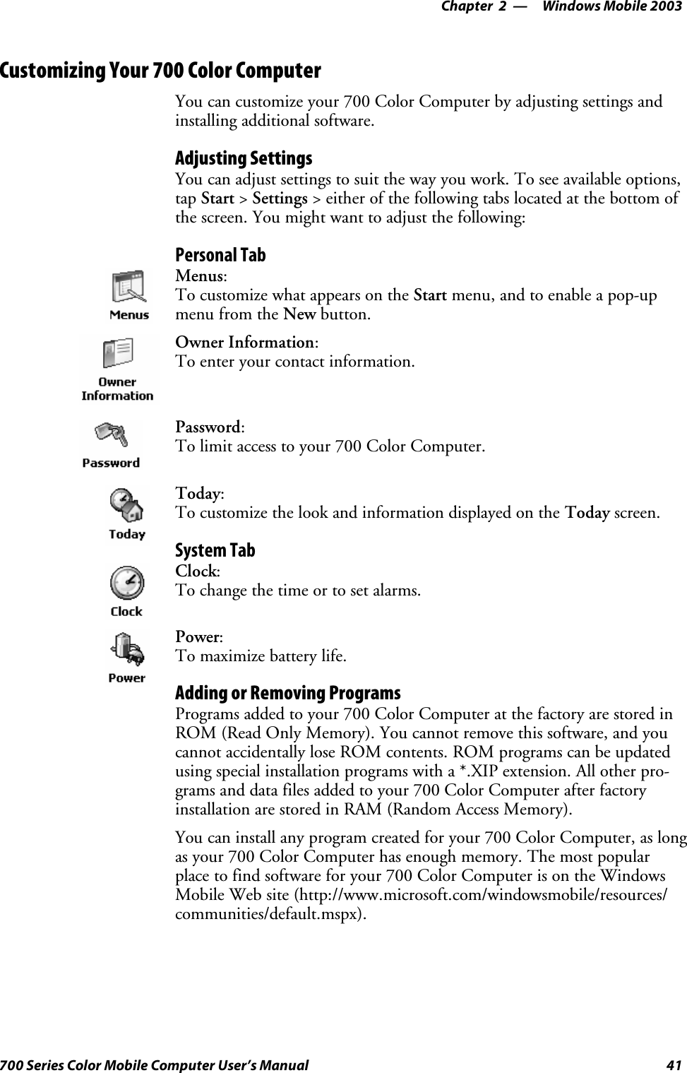
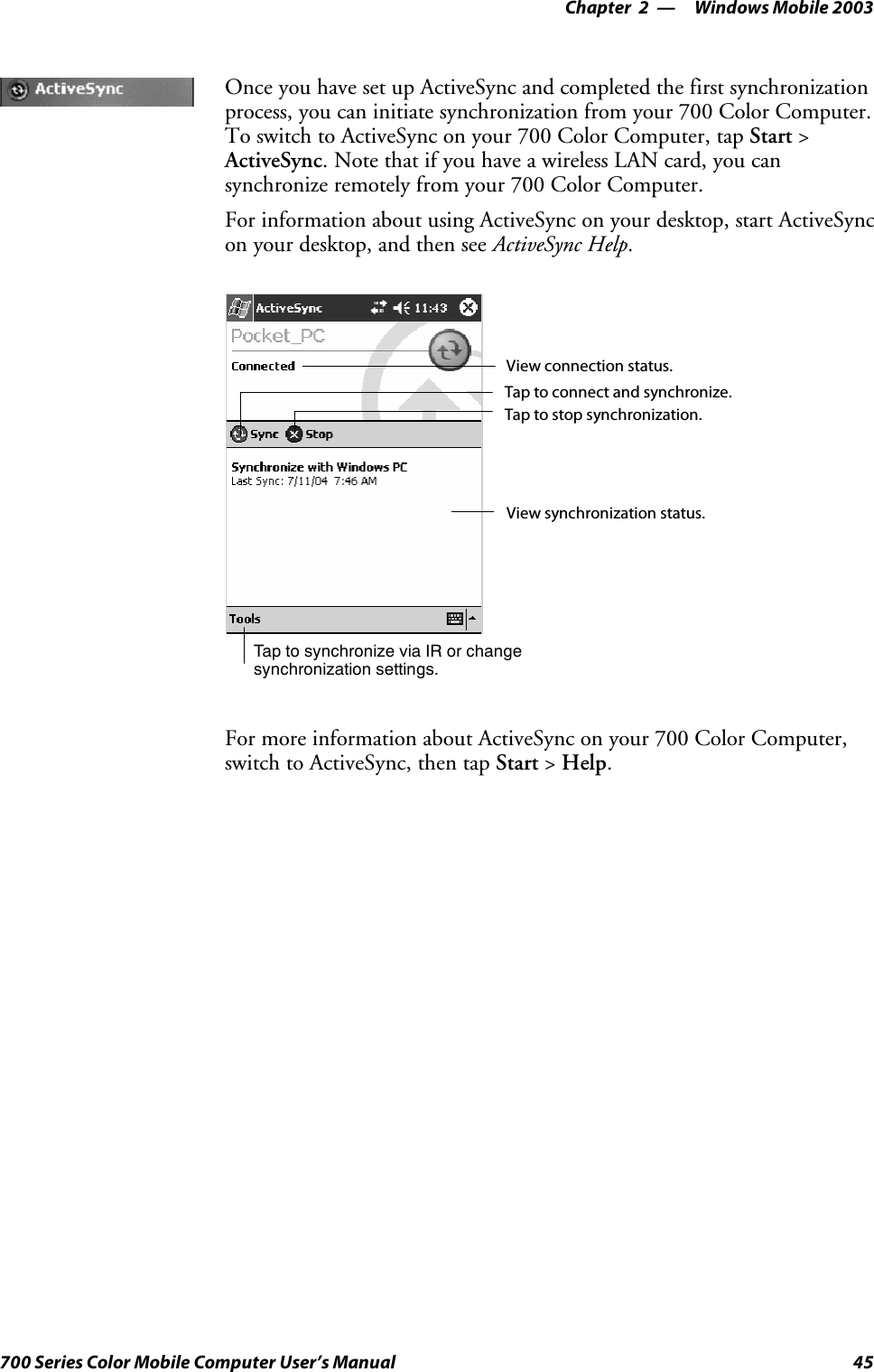
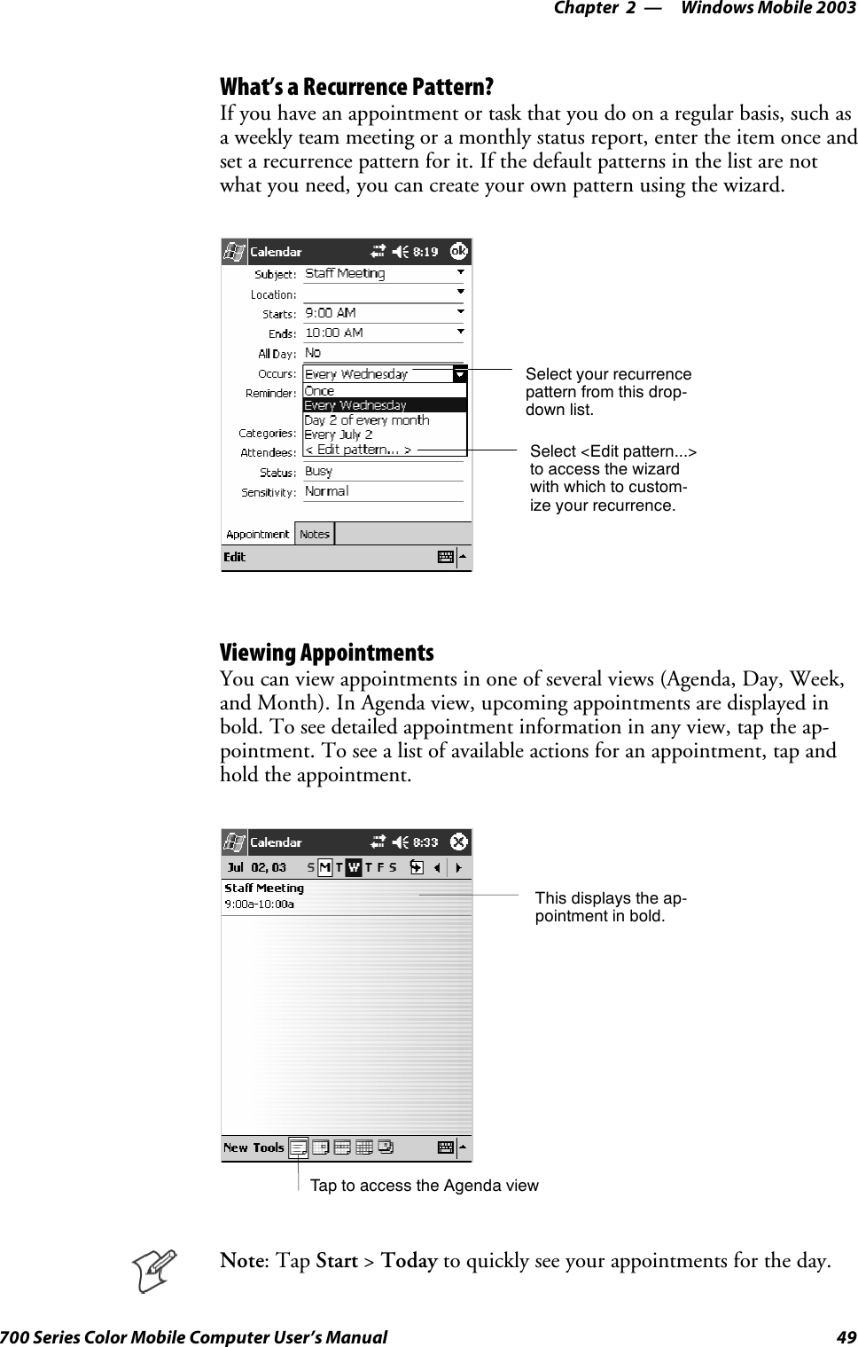
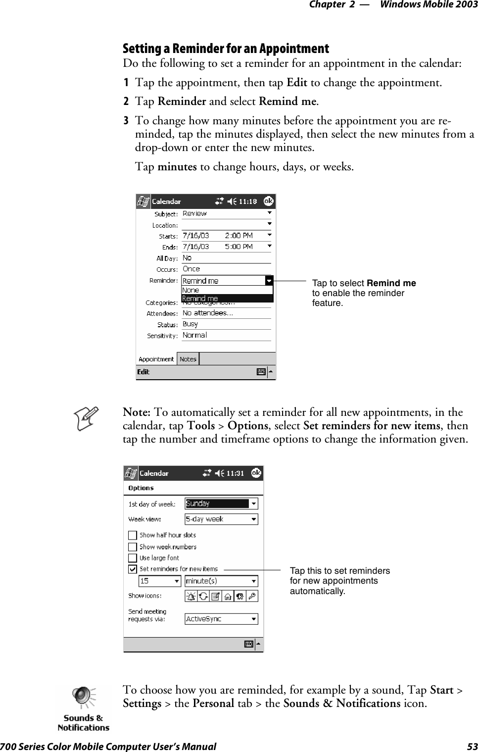
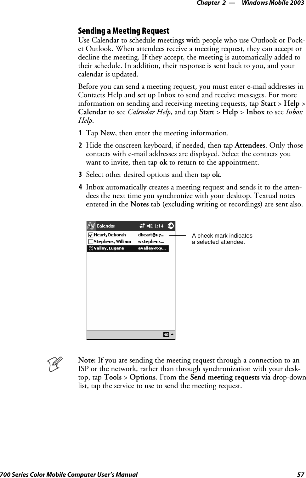
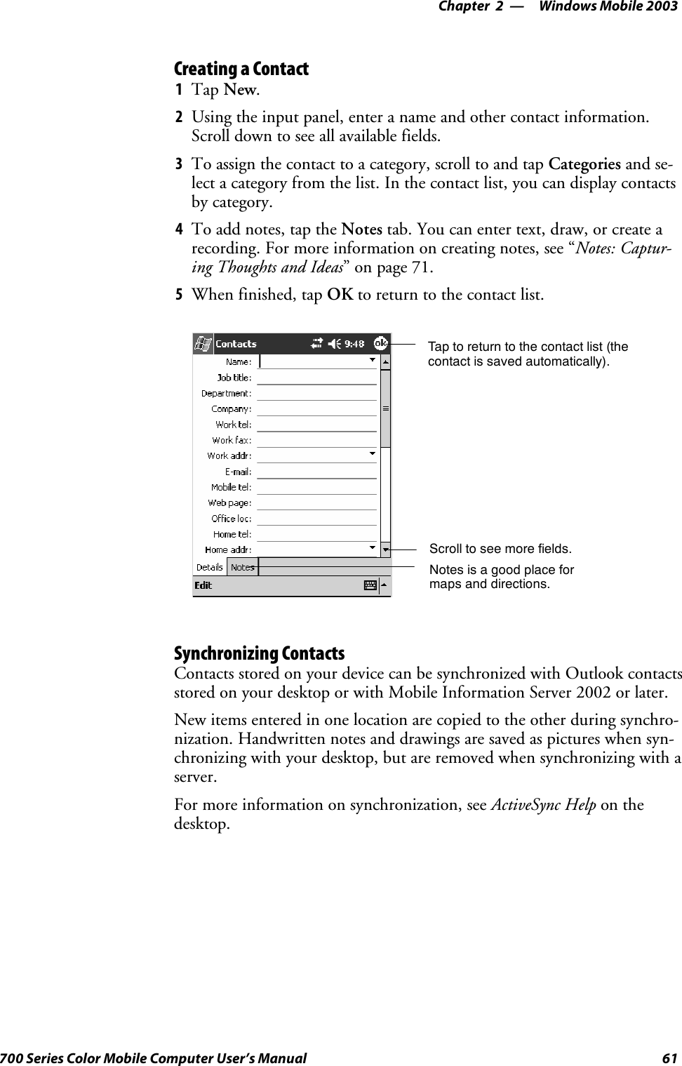
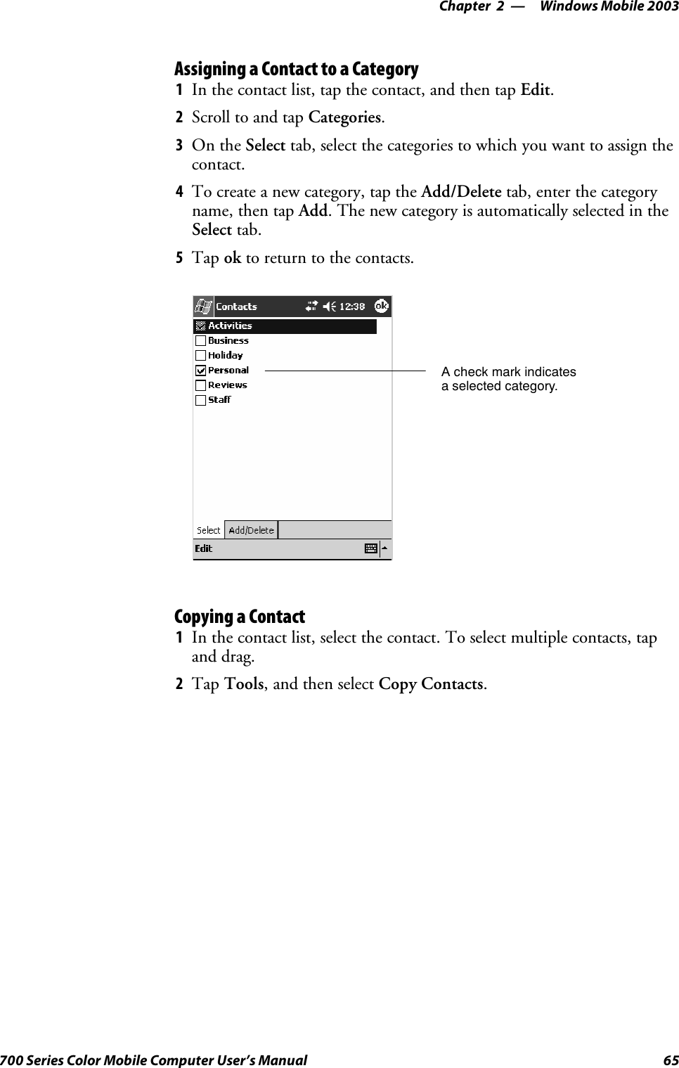
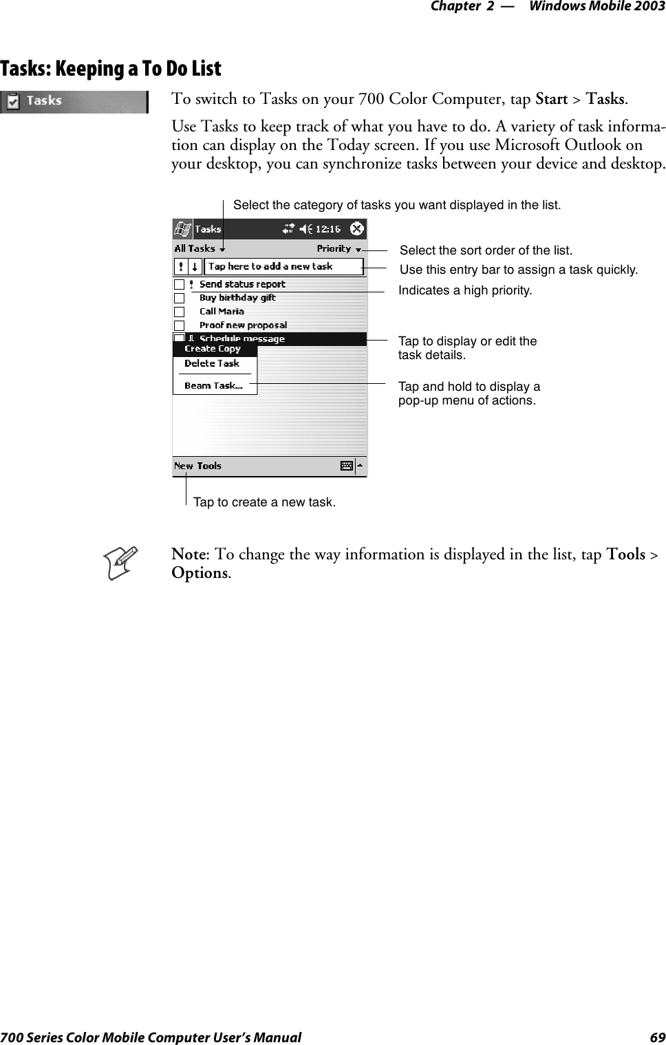
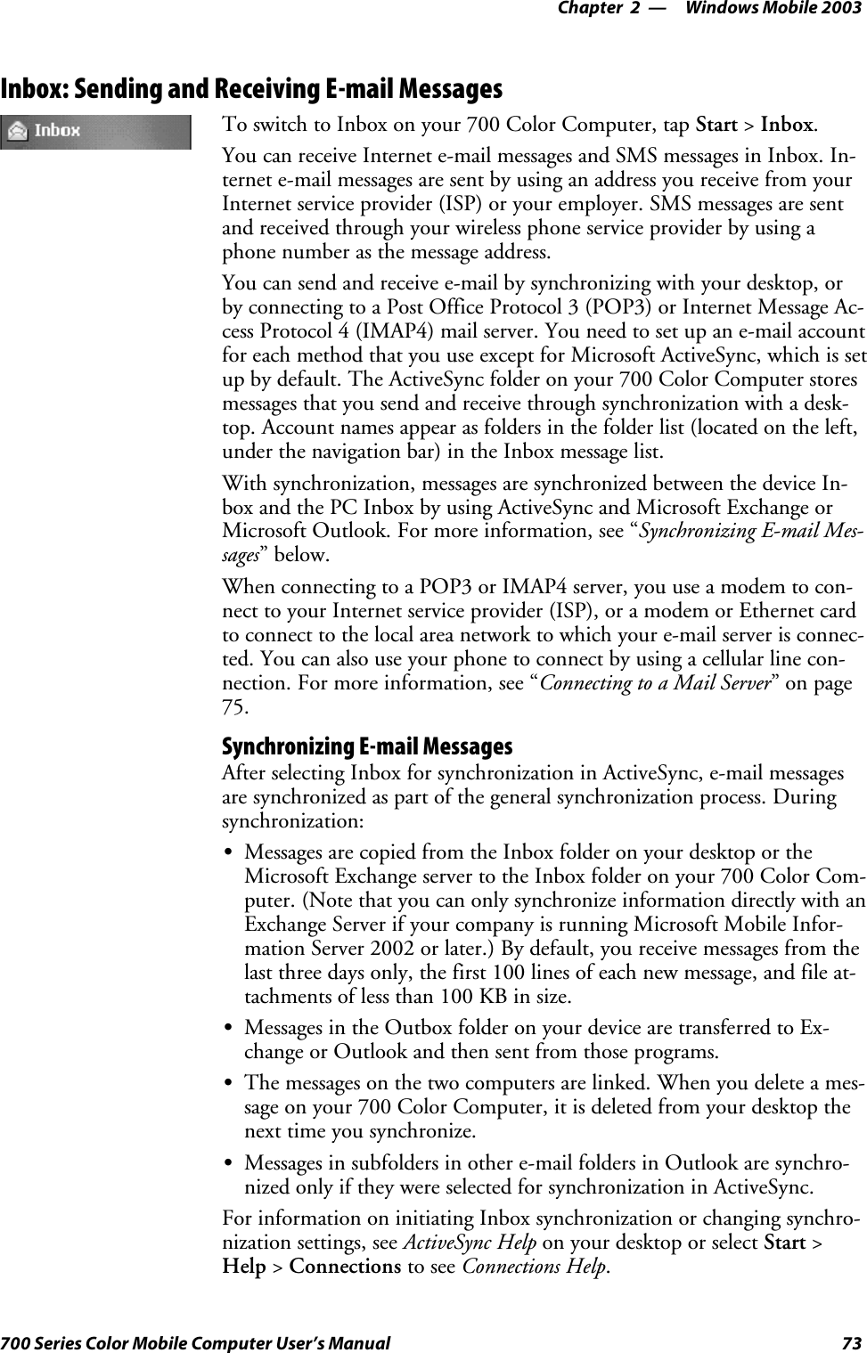
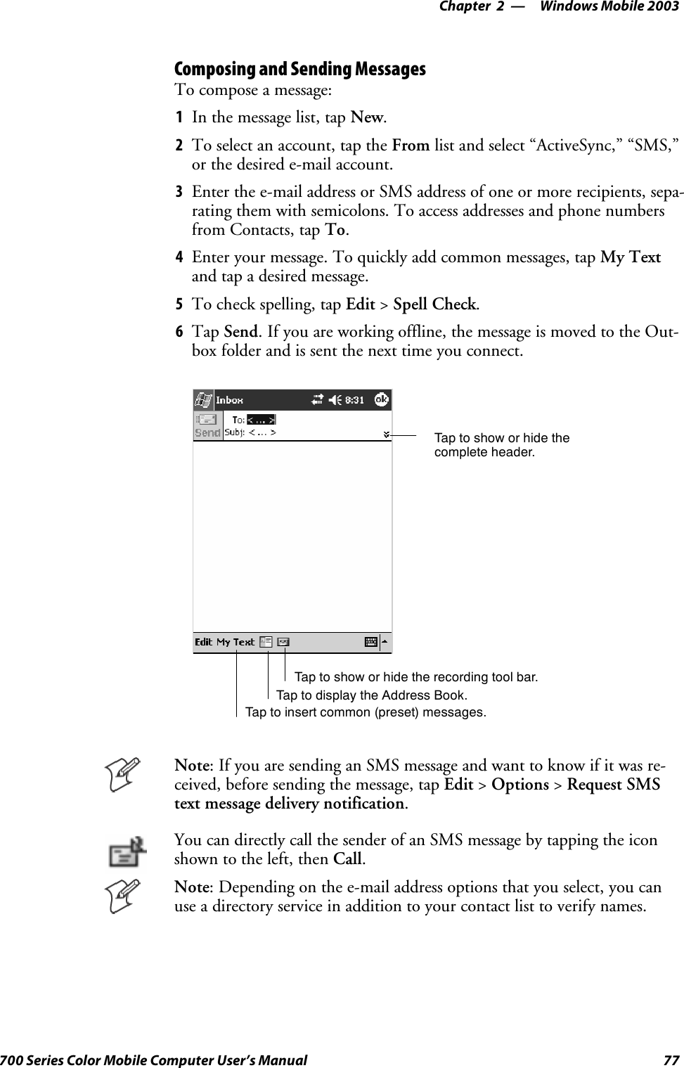
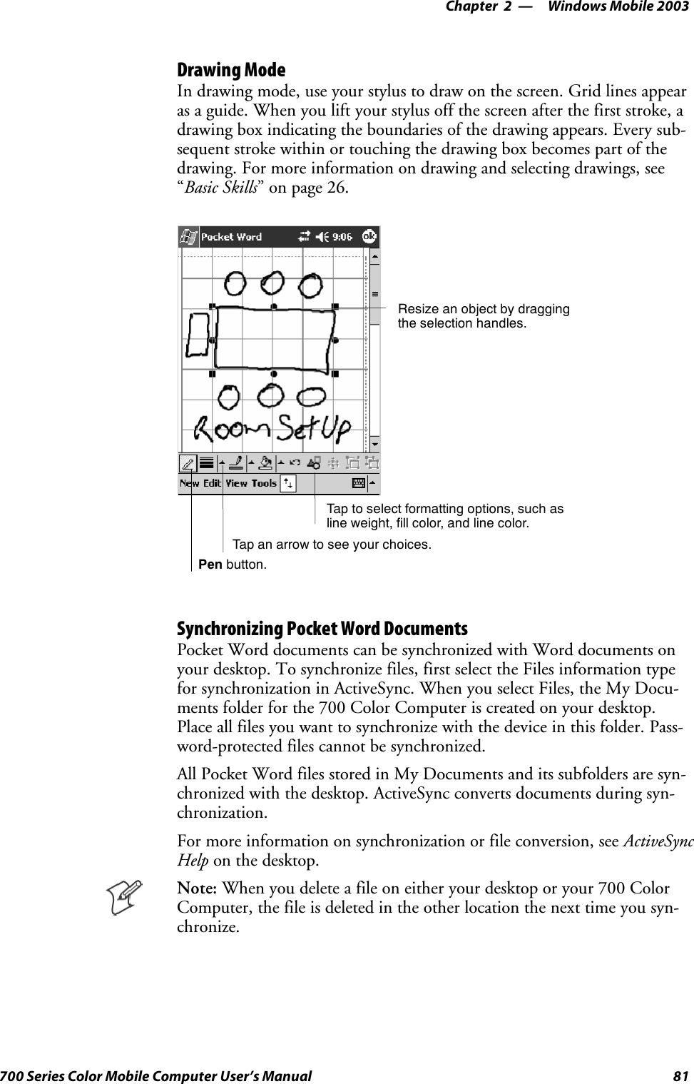
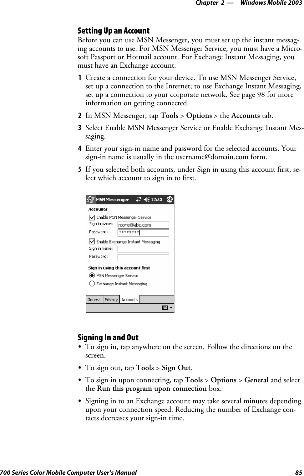
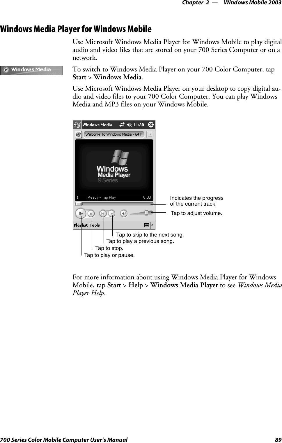
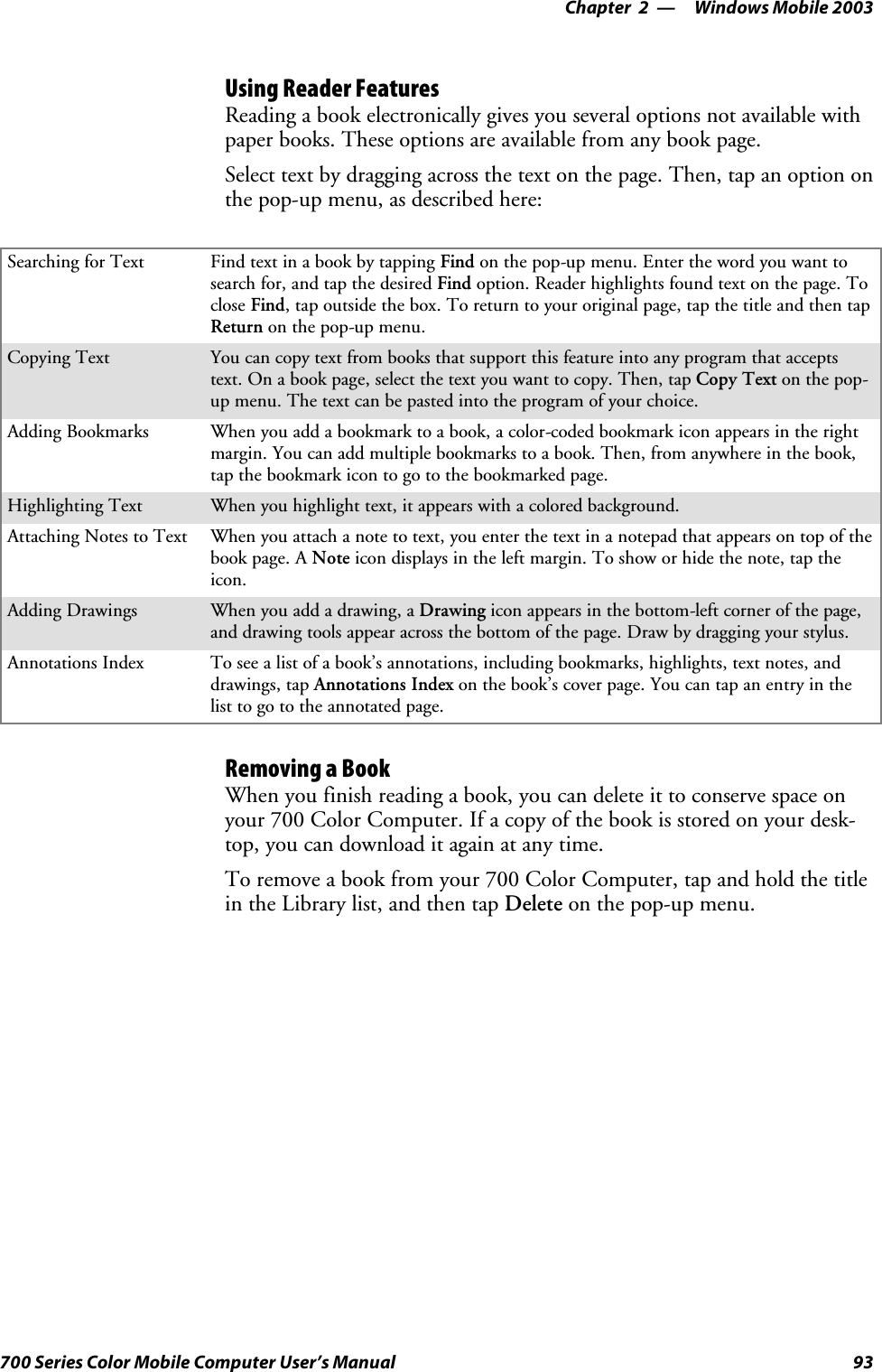
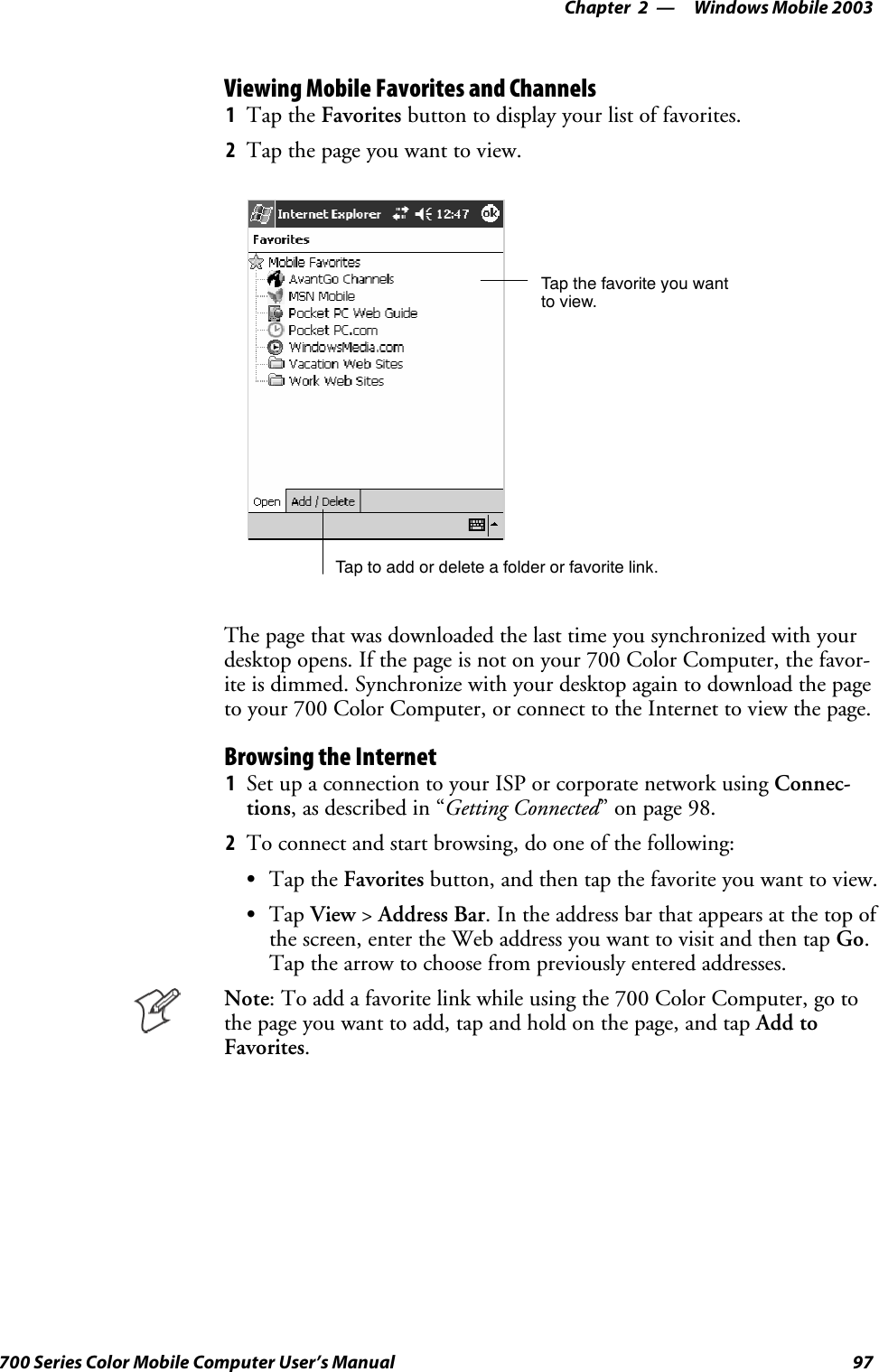
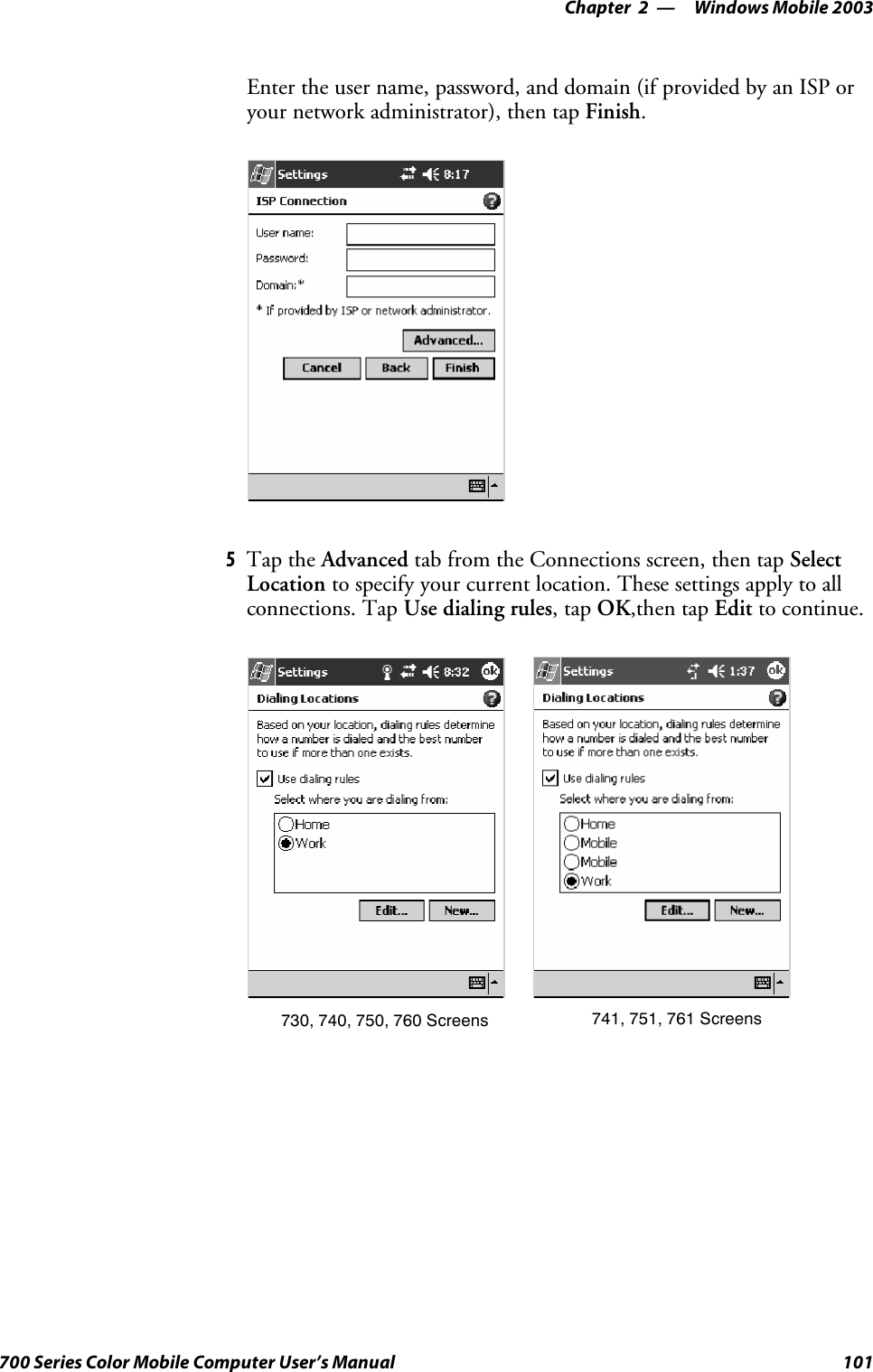
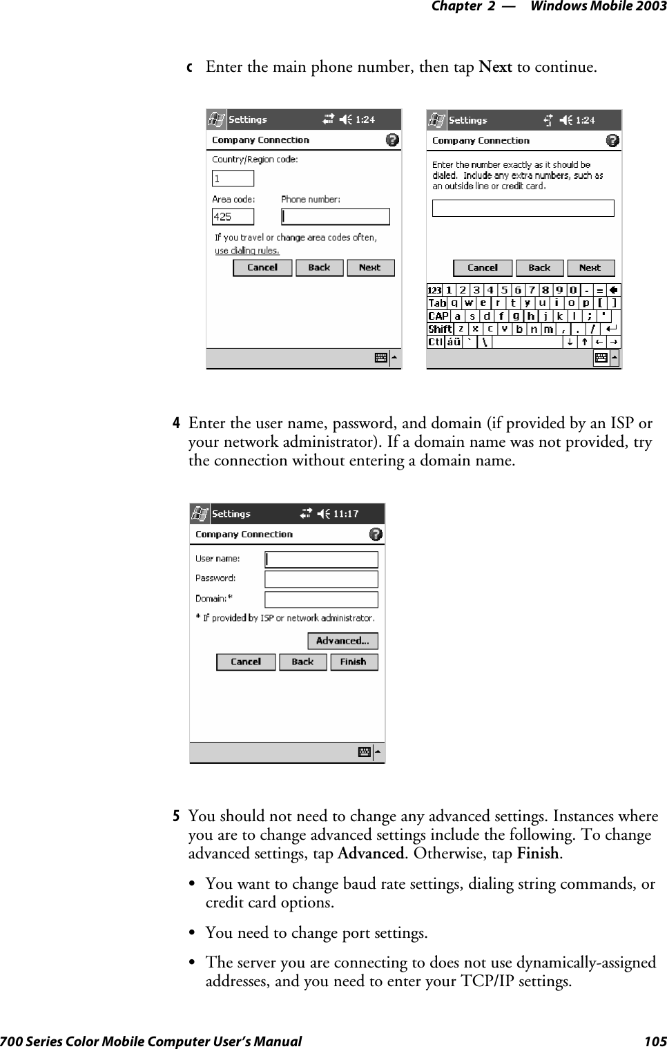
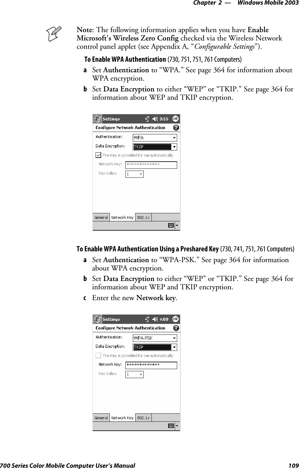
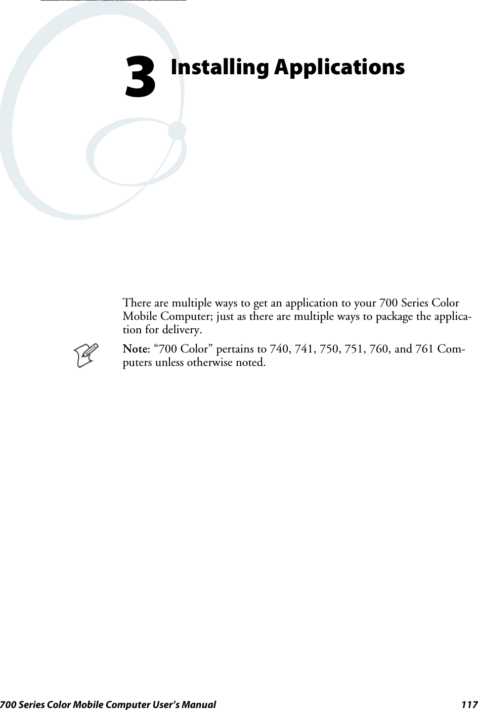
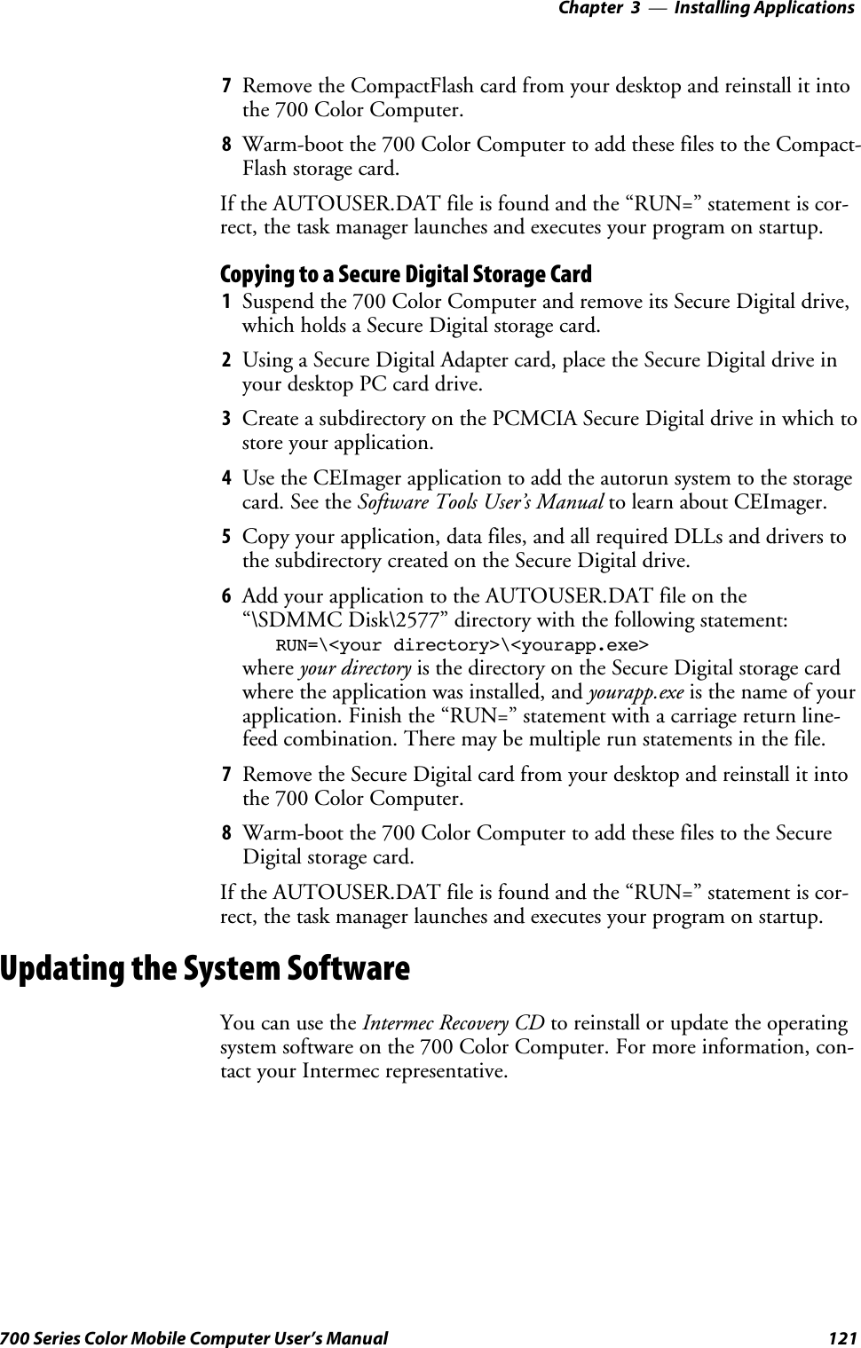
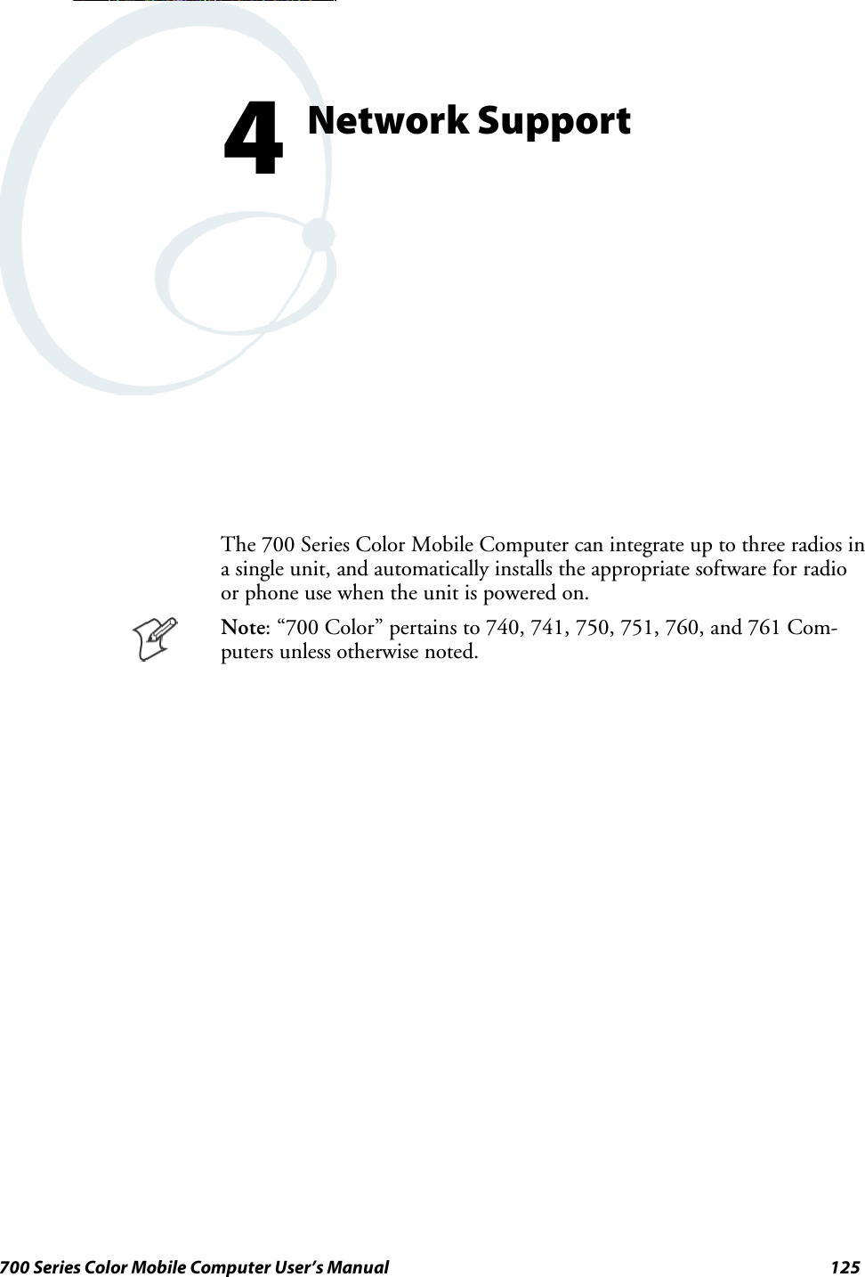
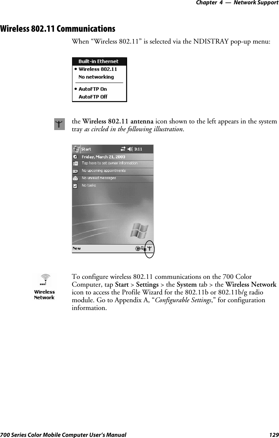
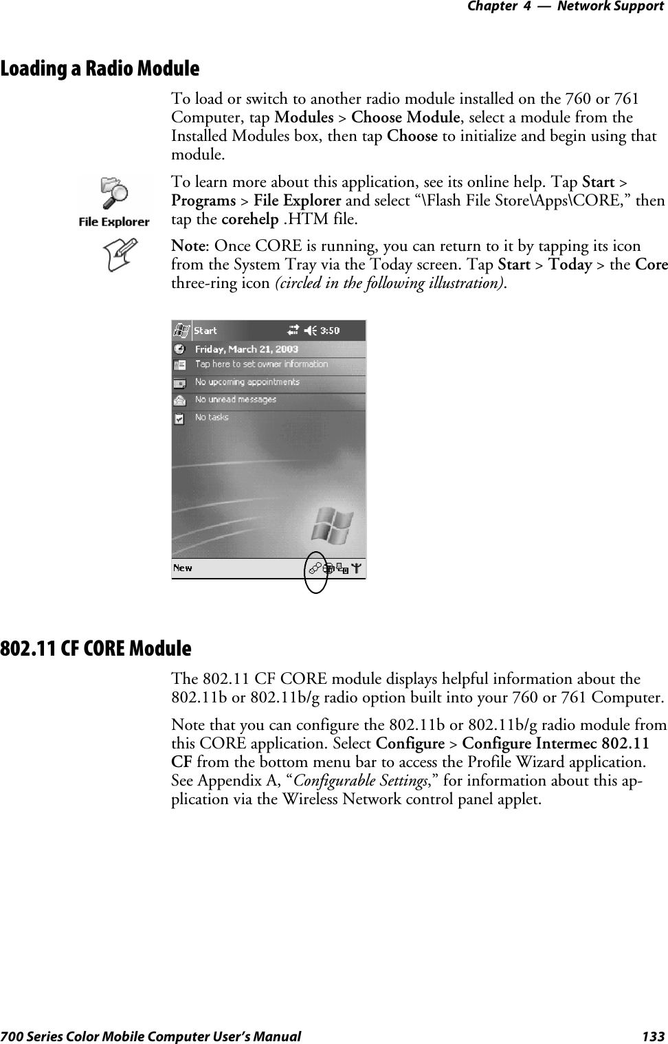
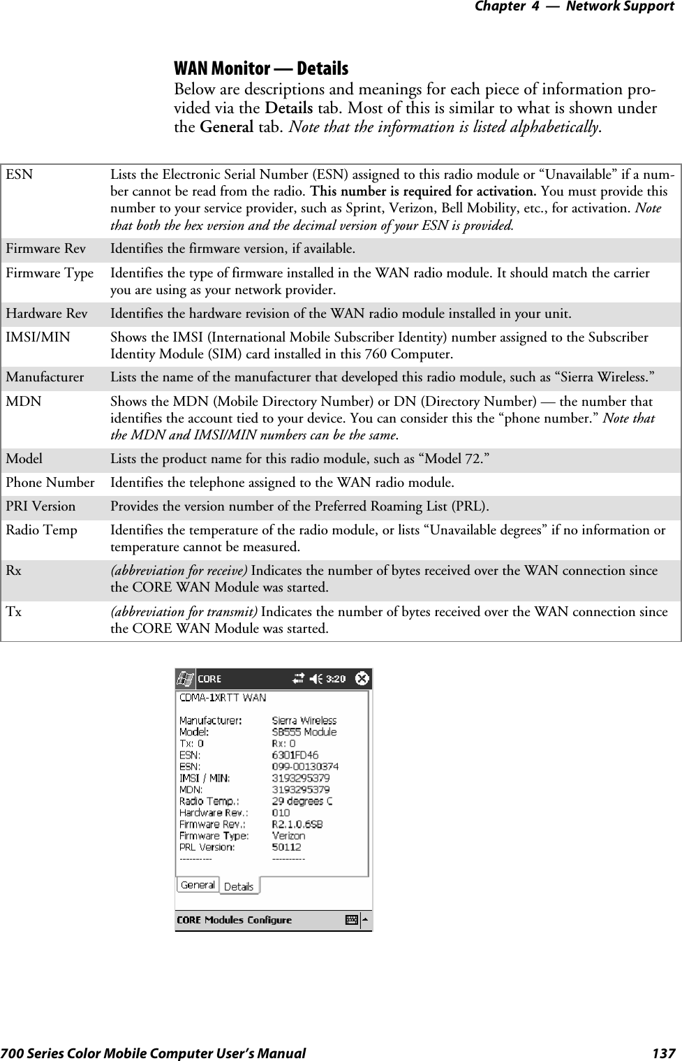
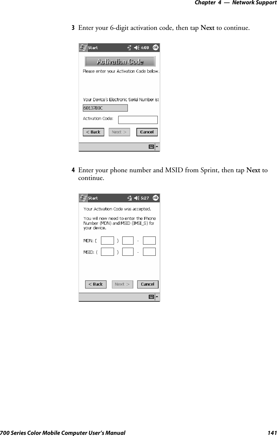
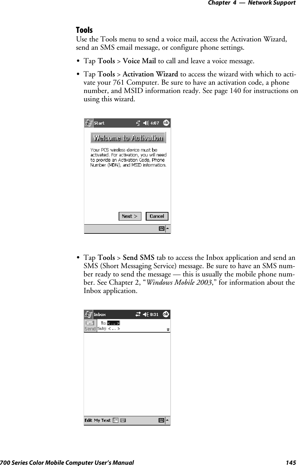
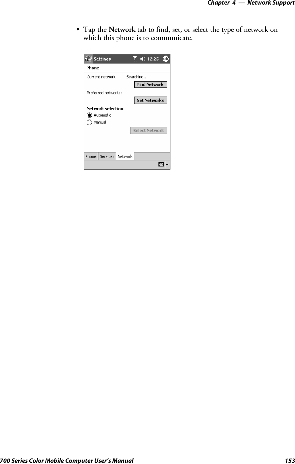
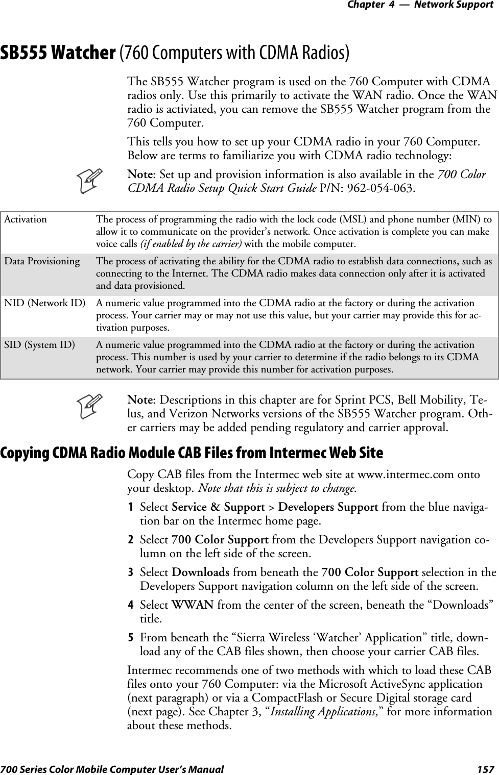
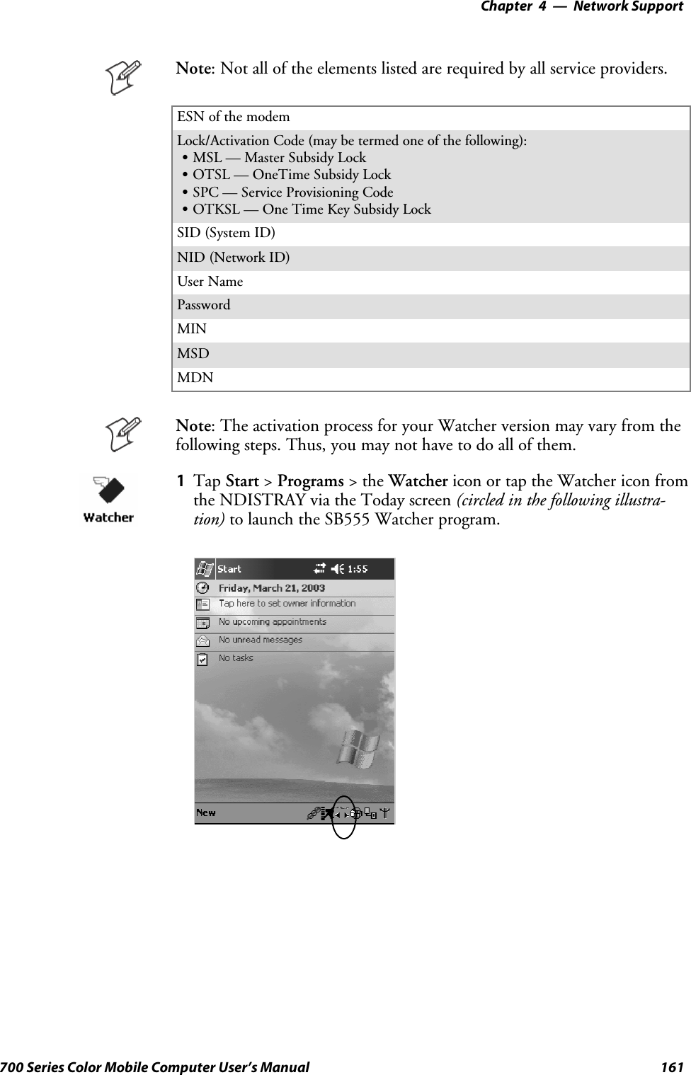
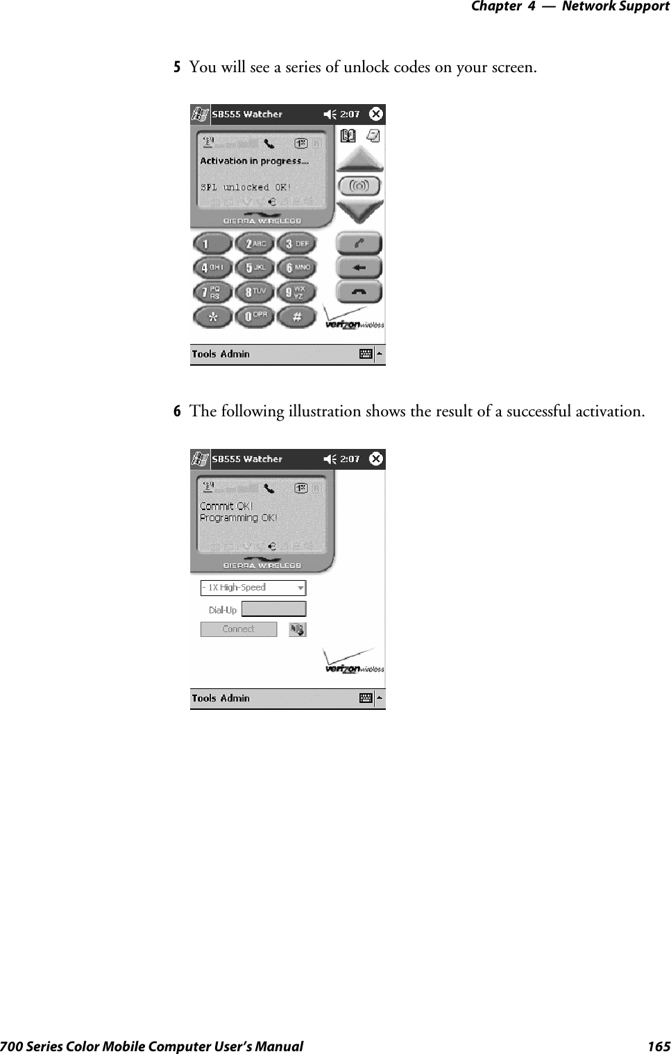
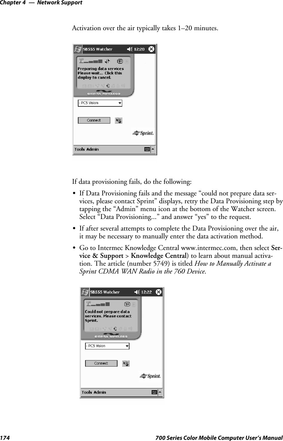
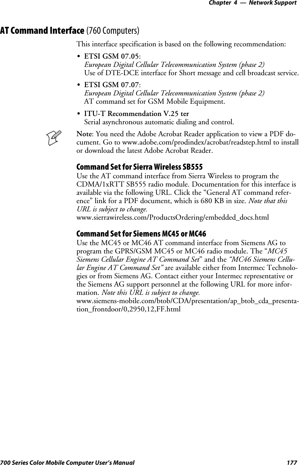
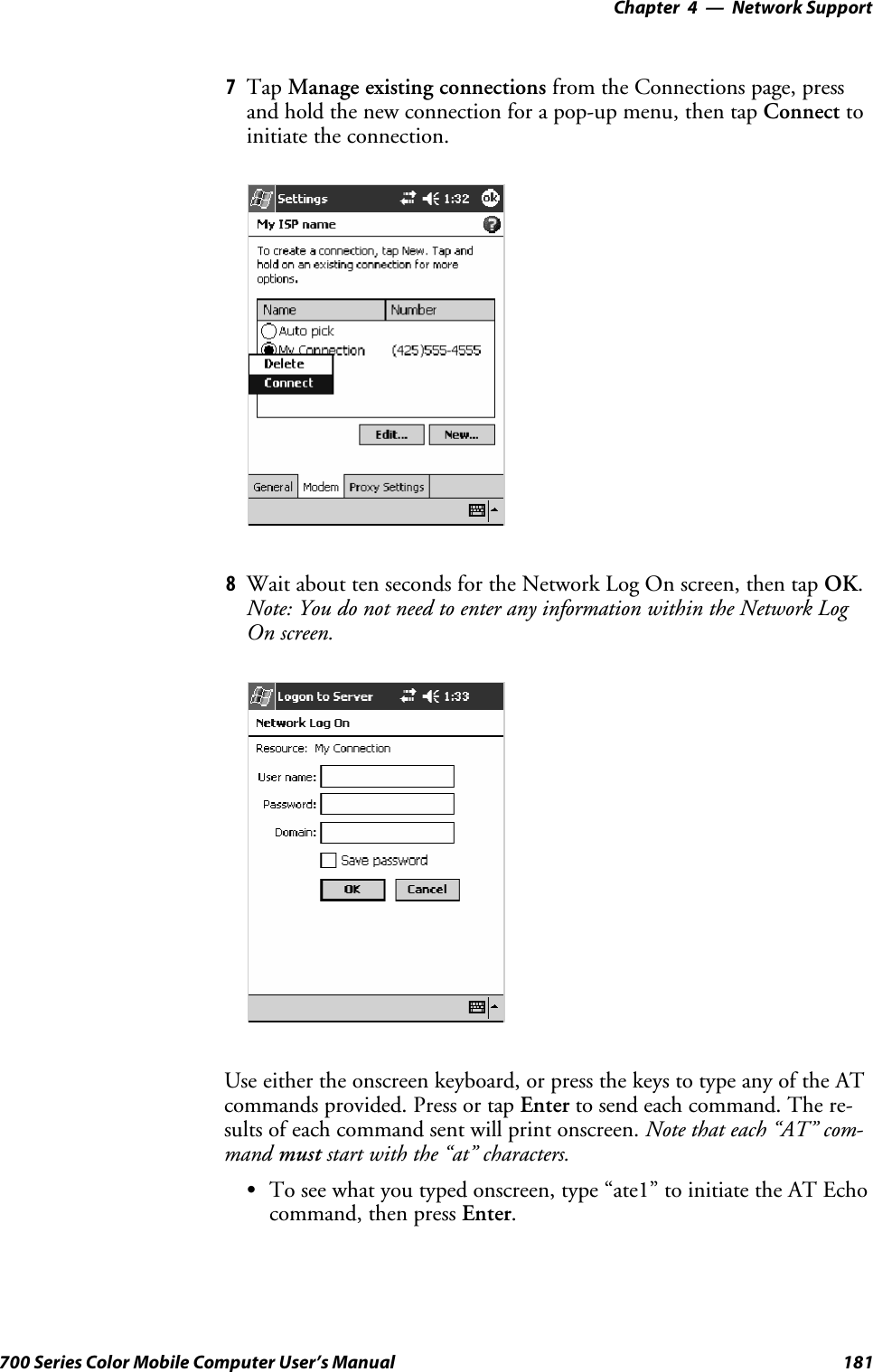
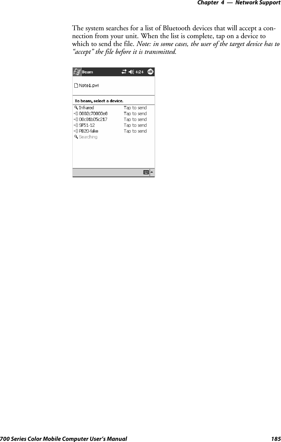
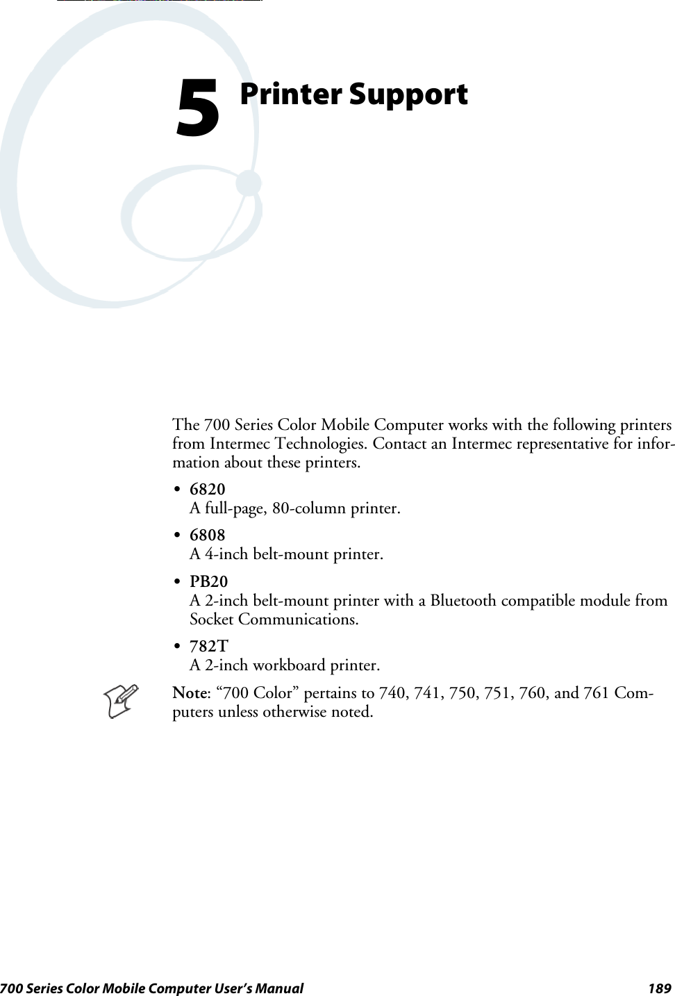
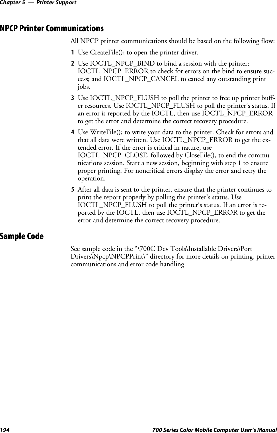
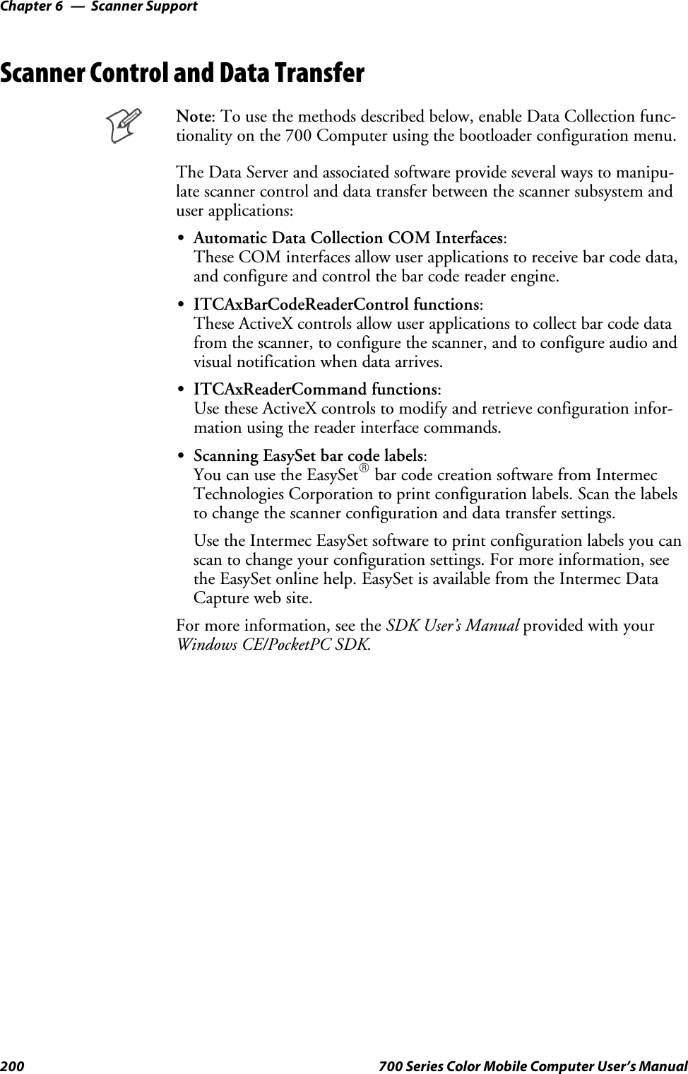
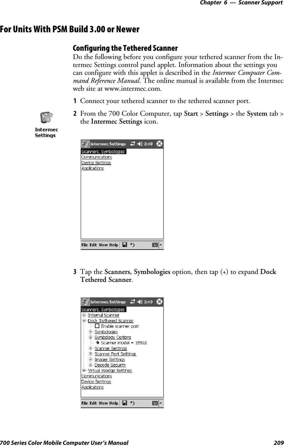
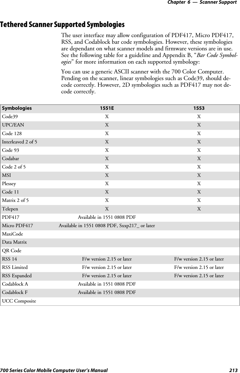
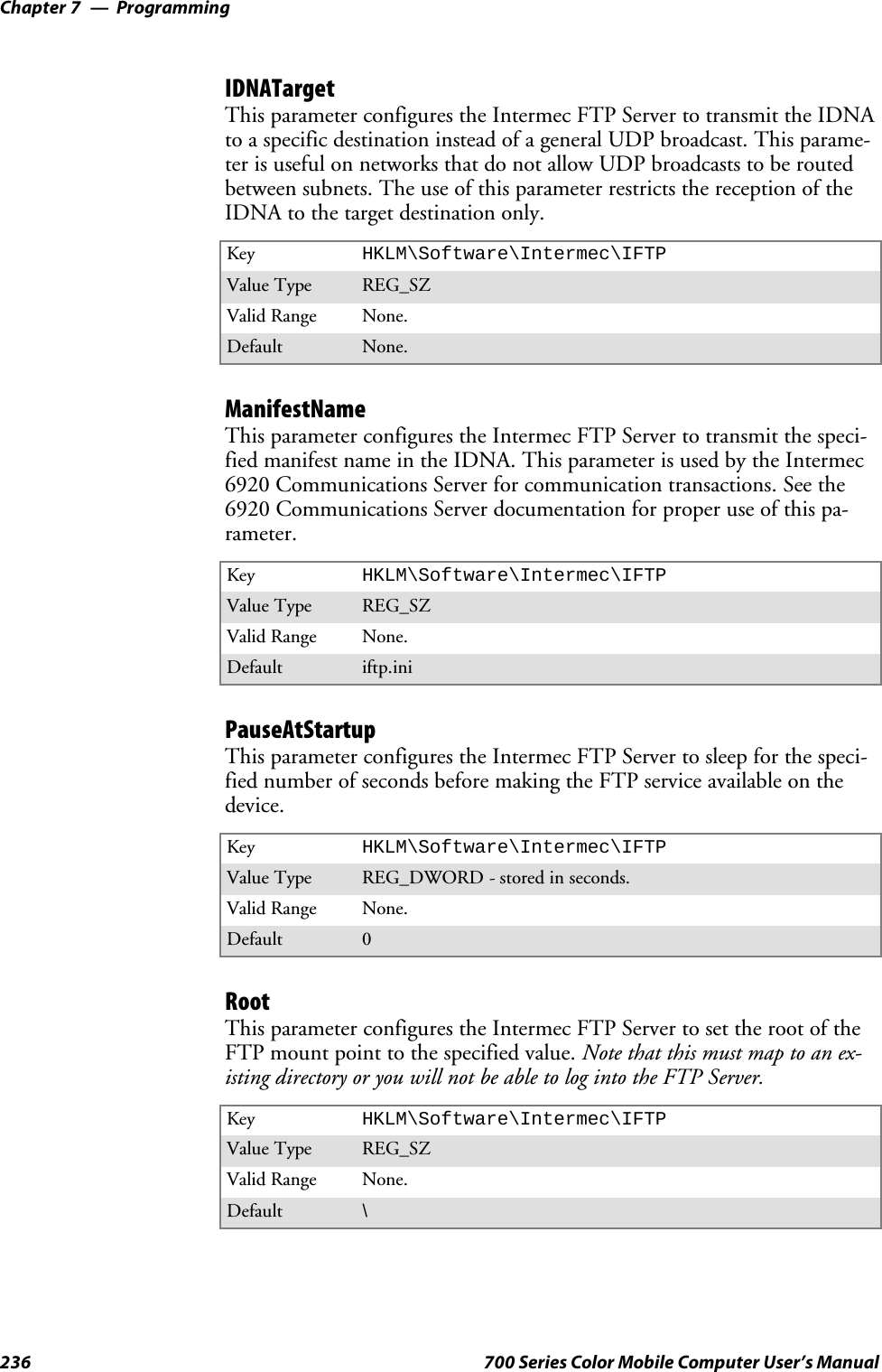
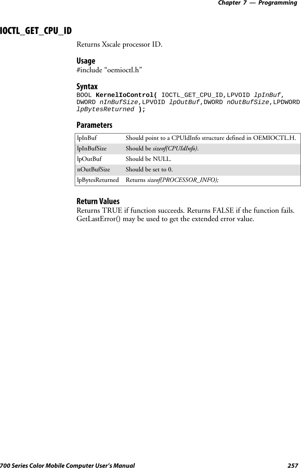
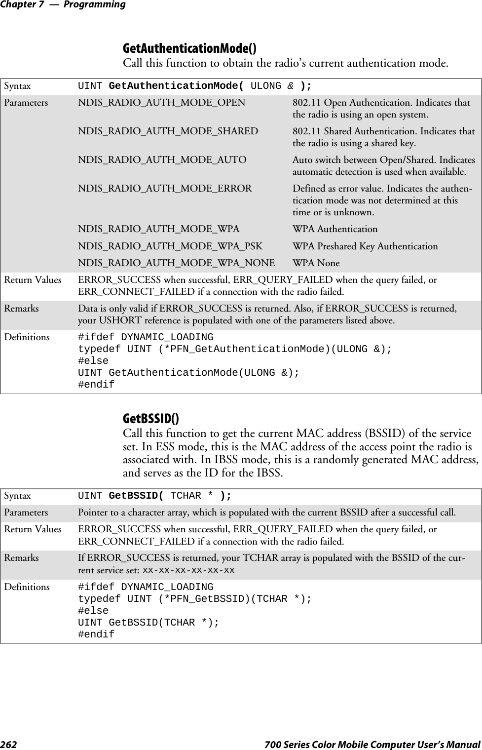
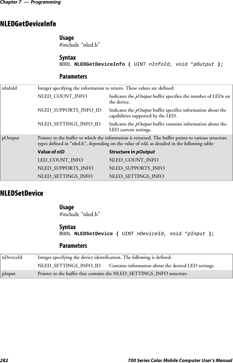
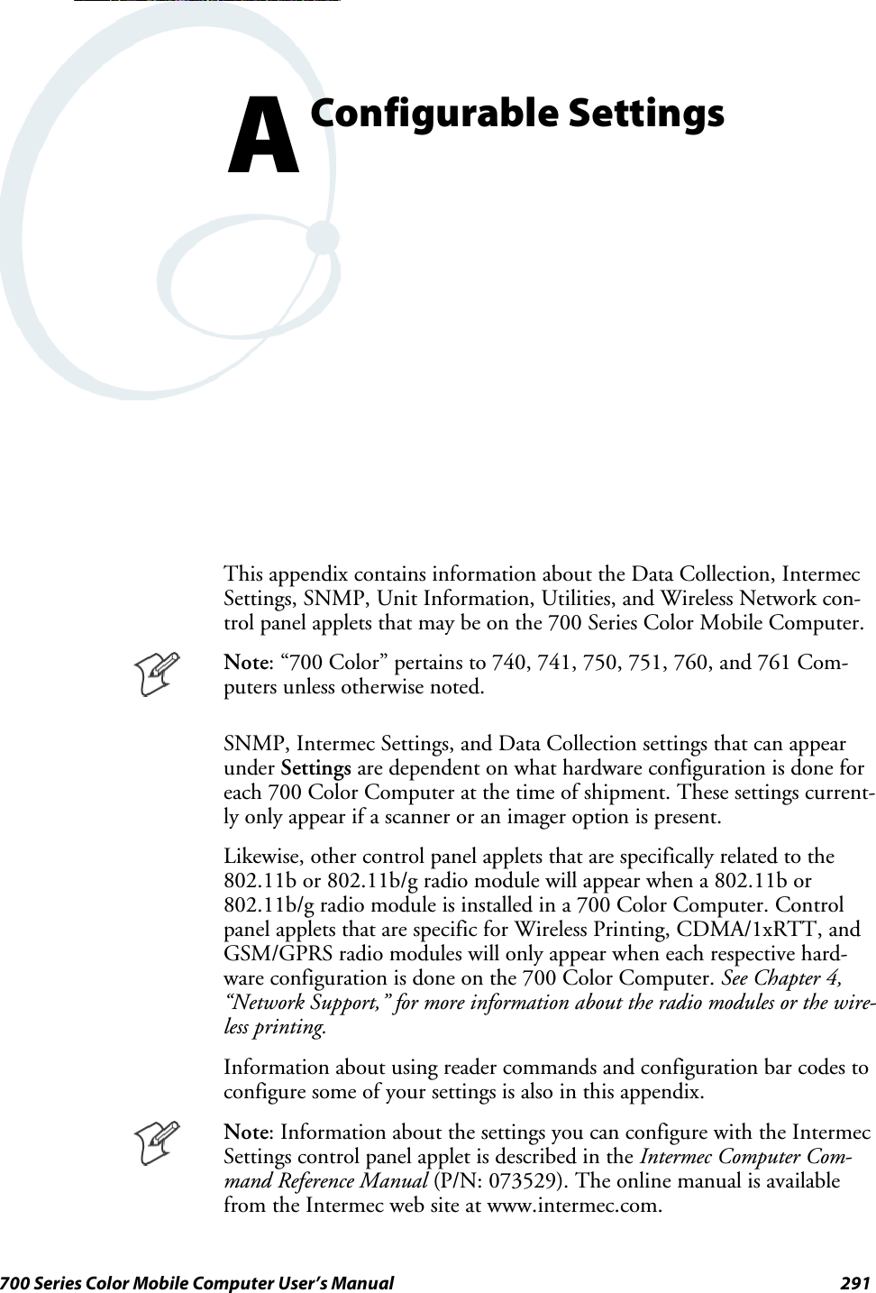
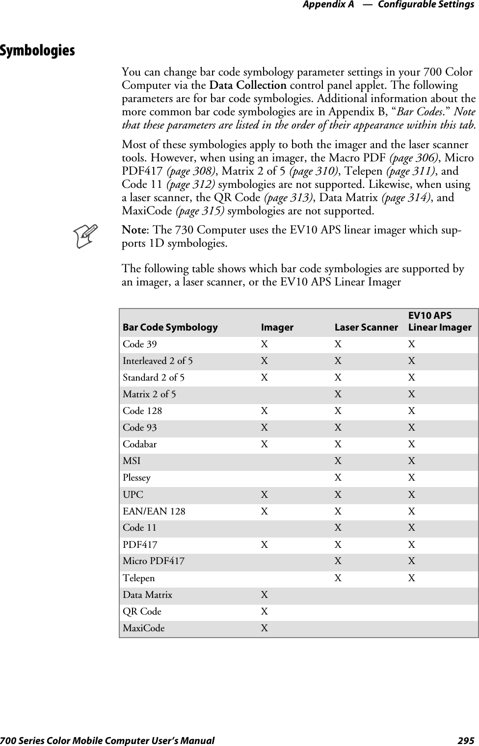
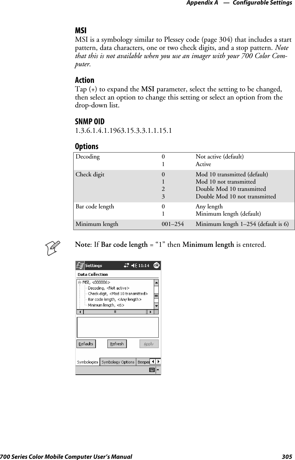
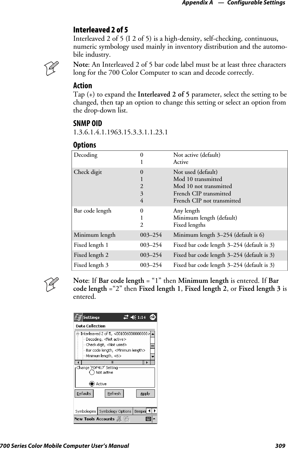
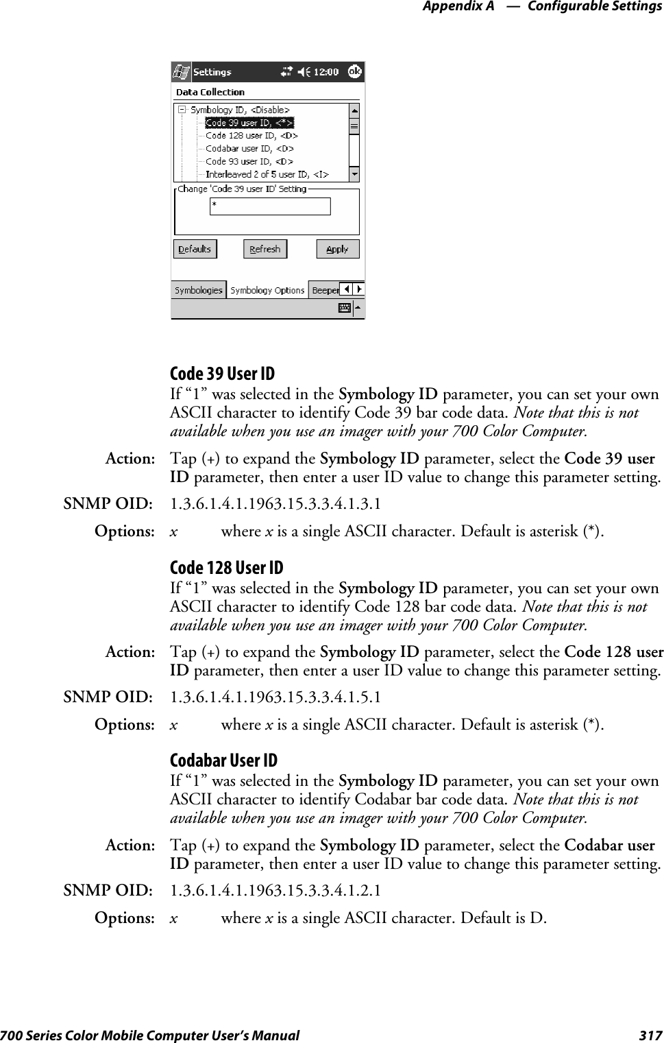
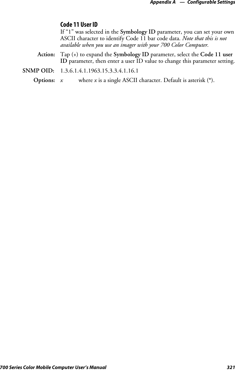
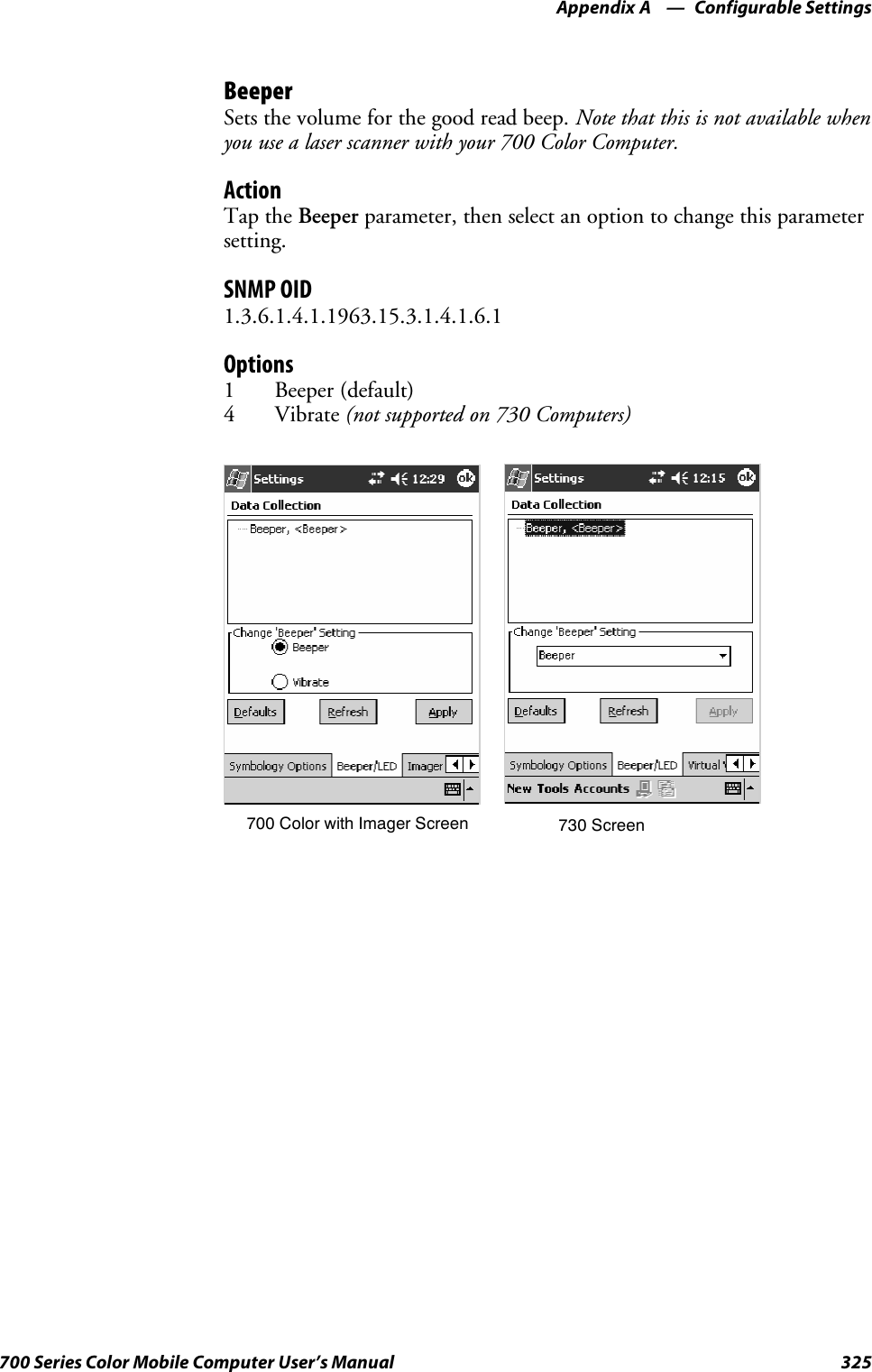
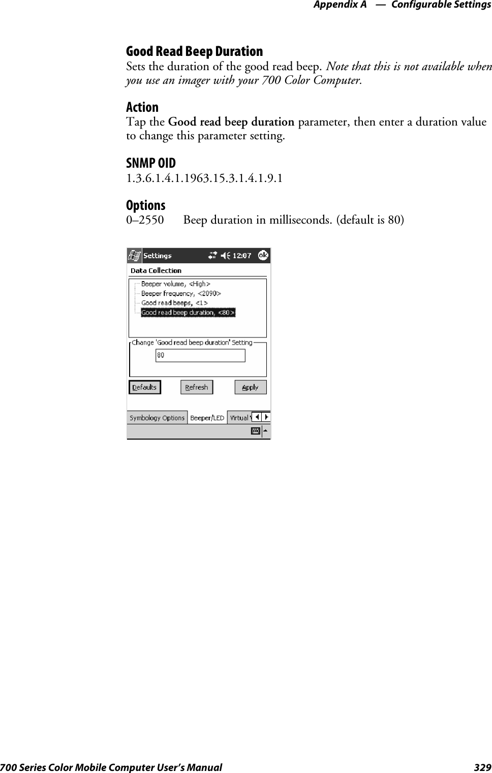
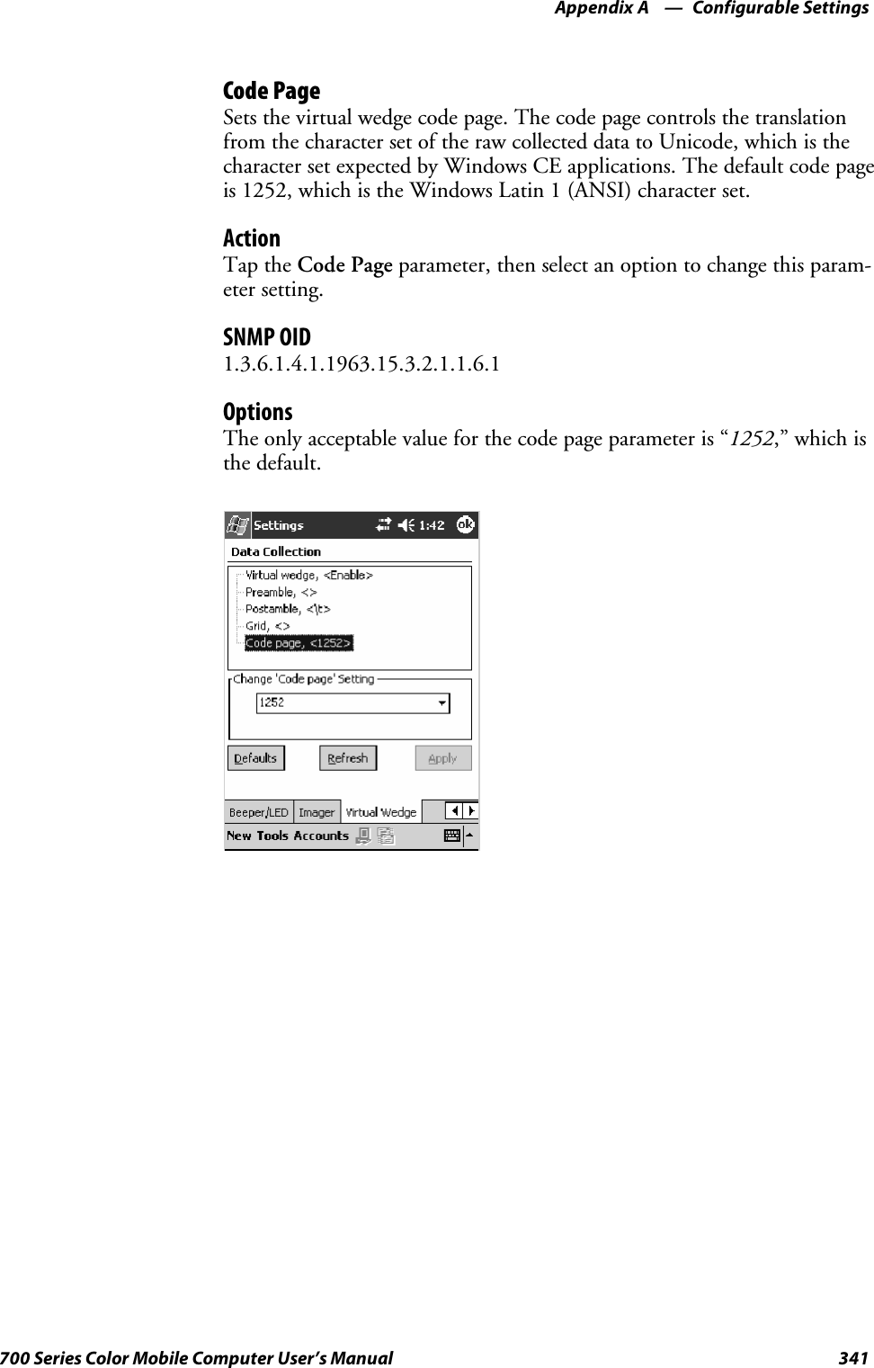
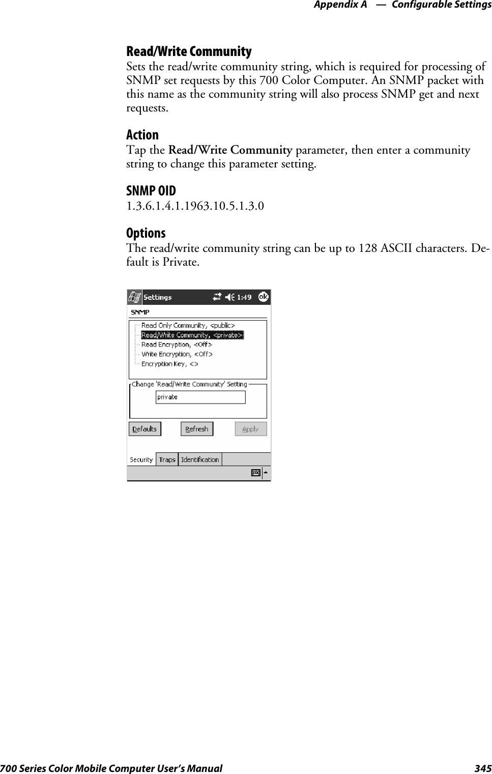
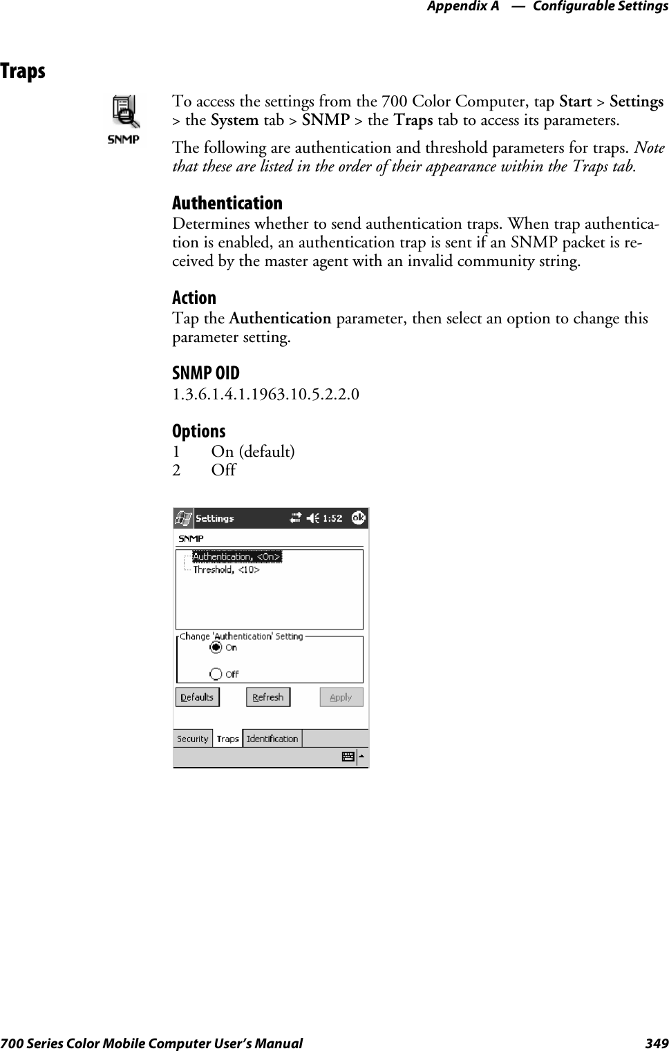
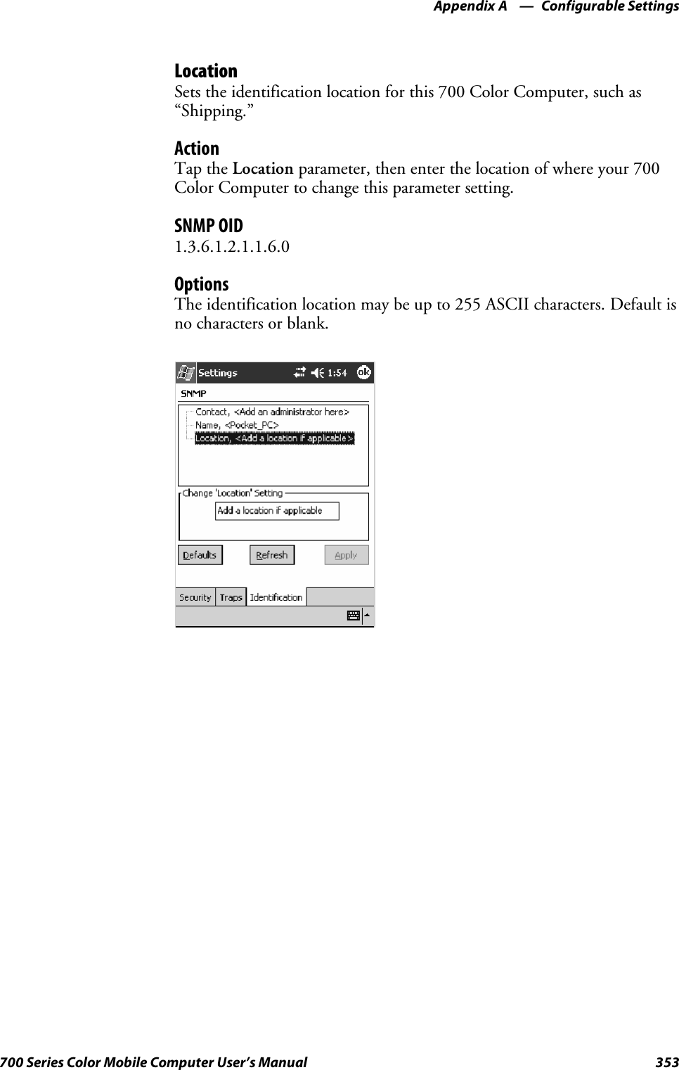
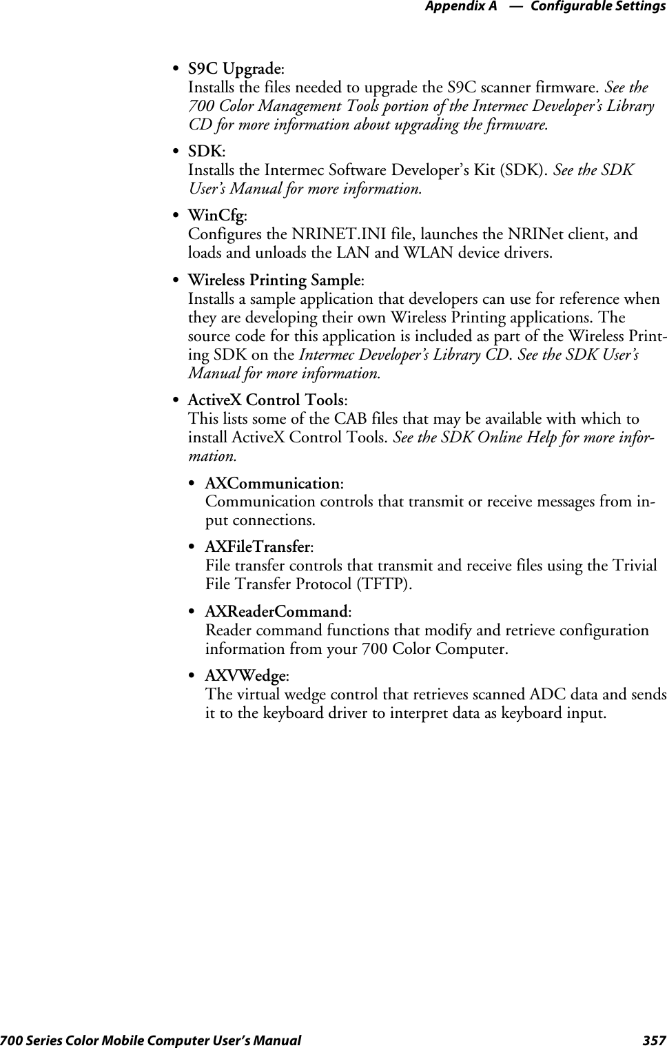
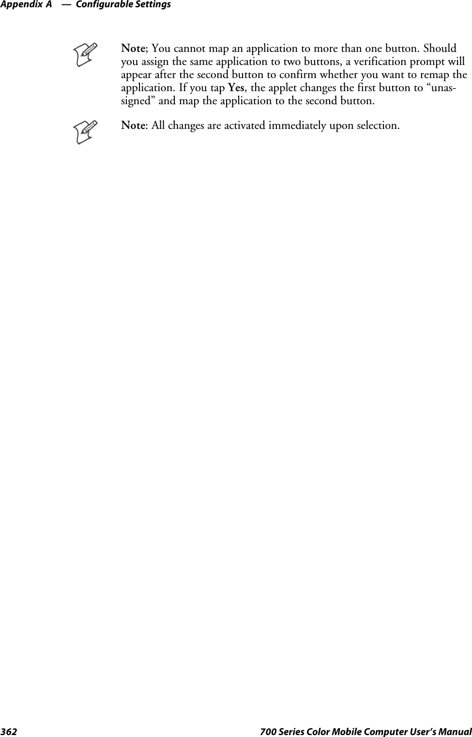
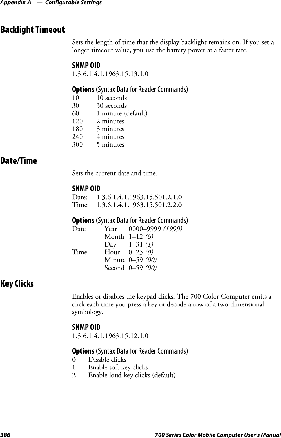
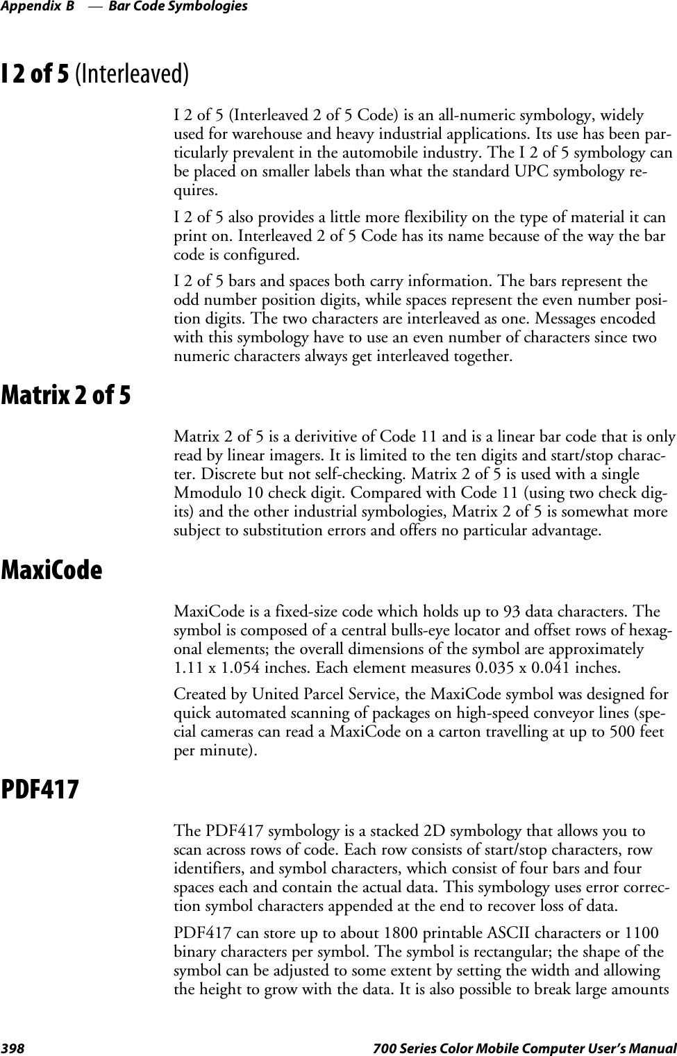
![IntroductionChapter —112 700 Series Color Mobile Computer User’s ManualKey SequencesUse the following key sequences to enter characters into your 700 ColorComputer using either a numeric keypad or an alphanumeric keypad.[Gold] or [Gold/White] Plane KeysThe [Gold] bplane key (numeric keypad) or the [Gold/White] cplanekey (alphanumeric keypad) provides you access to display controls, specialcharacters, and Pocket PC options.Press the [Gold] bkey or the [Gold/White] ckey for each gold planekey stroke you wish to make. For example to turn on the front light, pressandholdthe[Gold] bkey plus the 3key on the numeric keypad orpress and hold the [Gold/White] ckey plus the Ikey on the alphanu-meric keypad. To turn the front light off, press the appropriate keys again.Belowandonthenextpagearethekeysequences.Numeric KeypadThe following table lists sequences that use the [Gold] bplane key. SeeChapter 2, “Windows Mobile 2003,” for information about the Pocket PCapplications.Press the Keys To Do This[Gold]b3Toggle the backlight on or off (also goes through backlightpower levels if held down)[Gold]baAccess the Pocket PC Record application (see Note).[Gold]b4Access the Pocket PC Calendar application (see Note).[Gold]b5Access the Pocket PC Contacts application (see Note).[Gold]b6Access the Pocket PC Tasks application (see Note).[Gold]b7Move up one page.[Gold]b8Enter an asterisk (*).[Gold]b9Move down one page.[Gold]b0Access the Pocket PC Start menu.[Gold]beEnter an at symbol (@).[Gold]bKEnter a backslash (/).[Gold]bEEnter a minus sign (–).[Gold]bAEnter a plus sign (+).[Gold]b→Tab to the right.[Gold]b←Tab to the left.[Gold]bUIncrease volume[Gold]bDDecrease volumeNote: Pocket PC applications are accessible only if configured to do so in the App Launchportion of the Utilities control panel applet. See page 358 for more information.](https://usermanual.wiki/Intermec-Technologies/2610CF.700C-User-Manual-1-of-3/User-Guide-527885-Page-34.png)
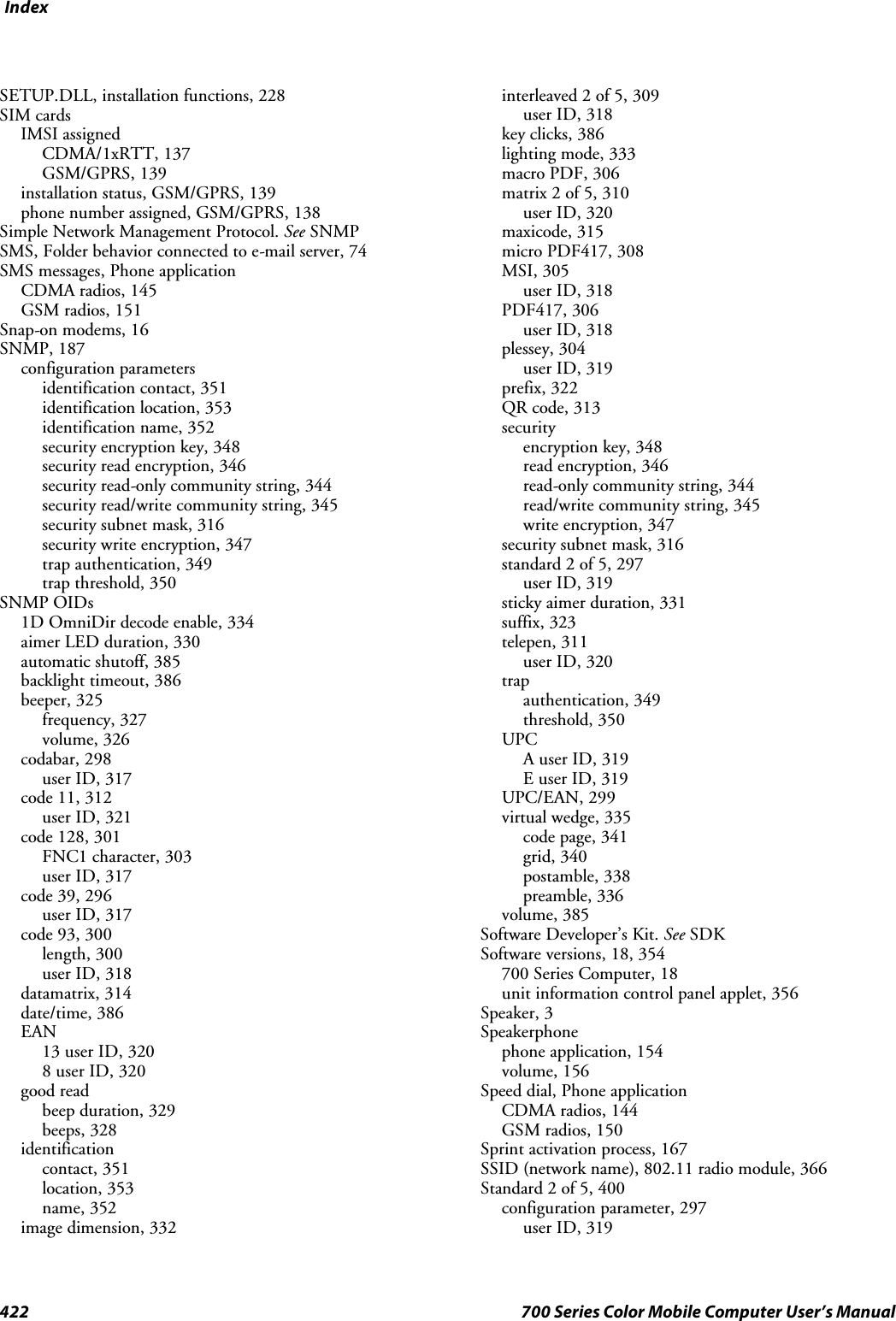
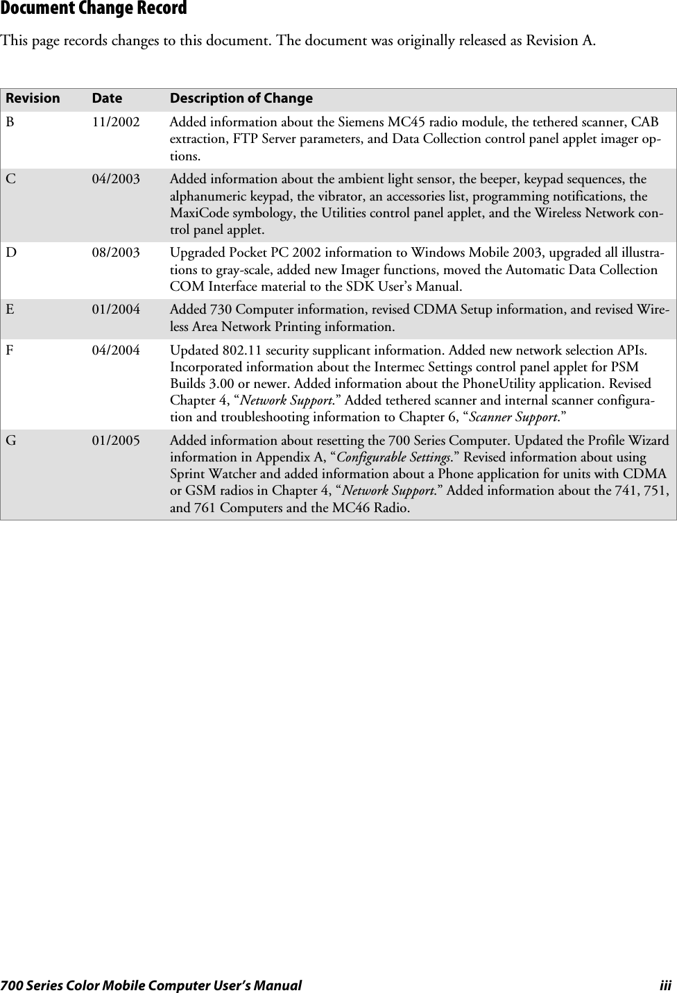
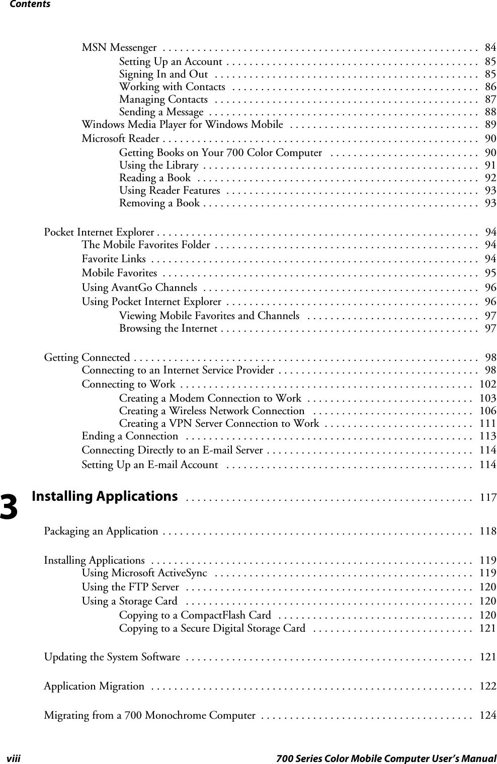
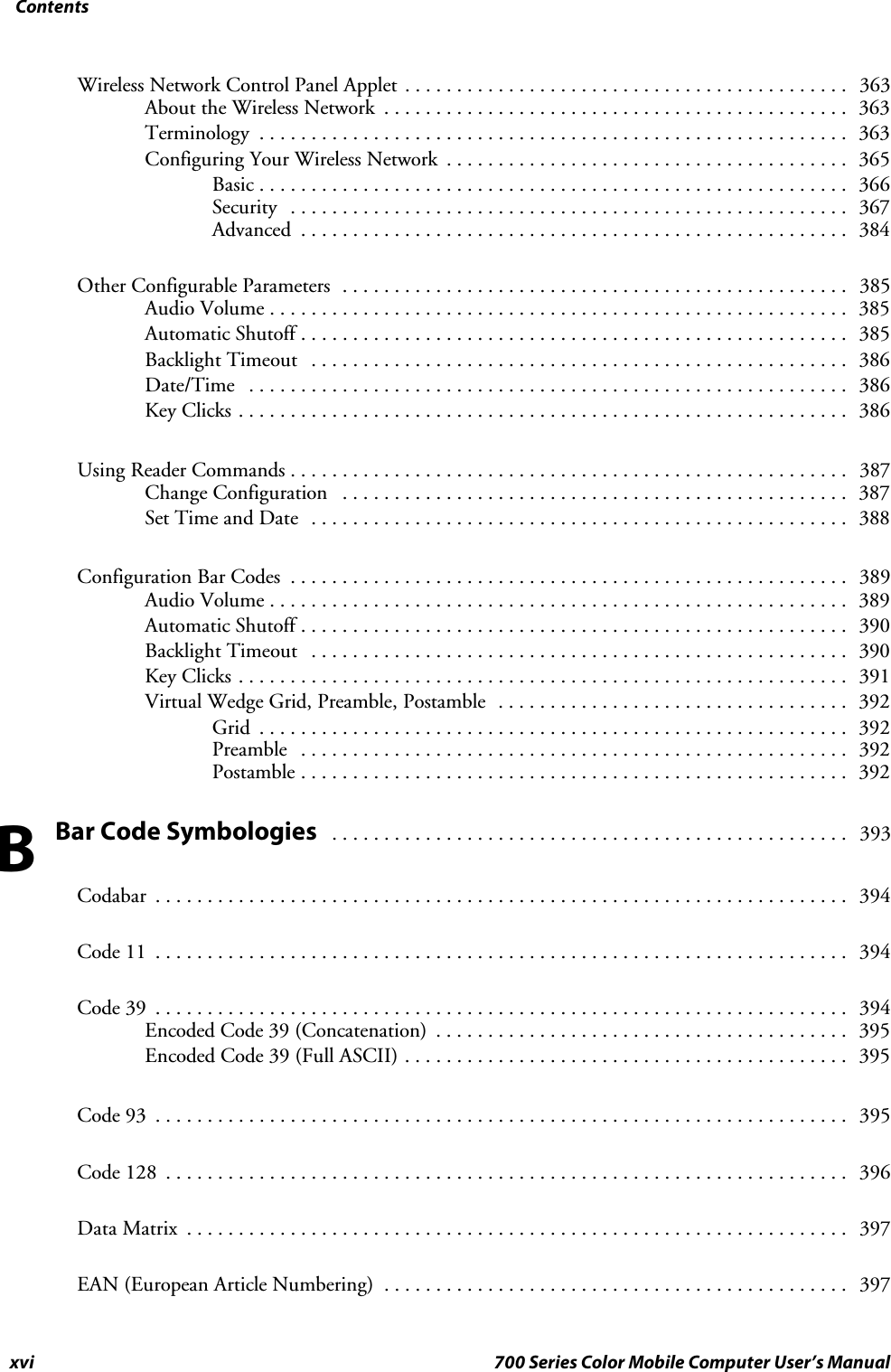
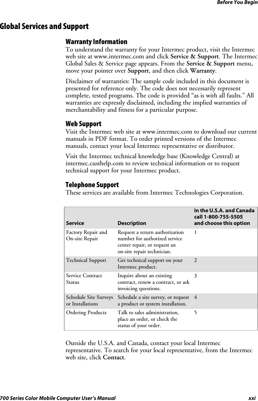
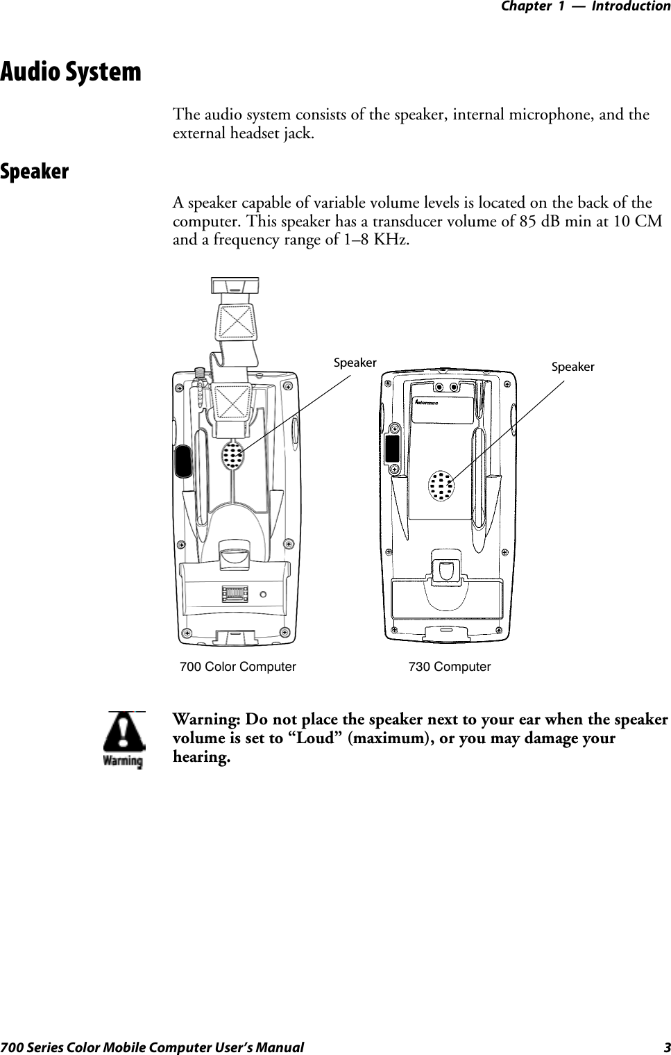
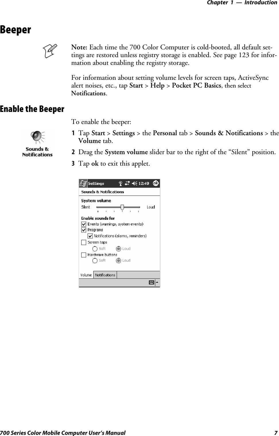
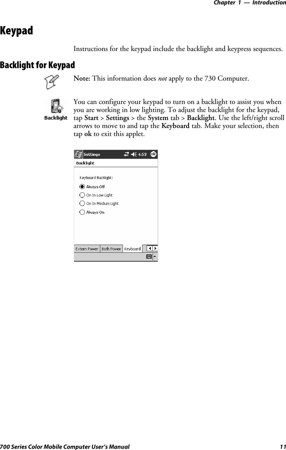
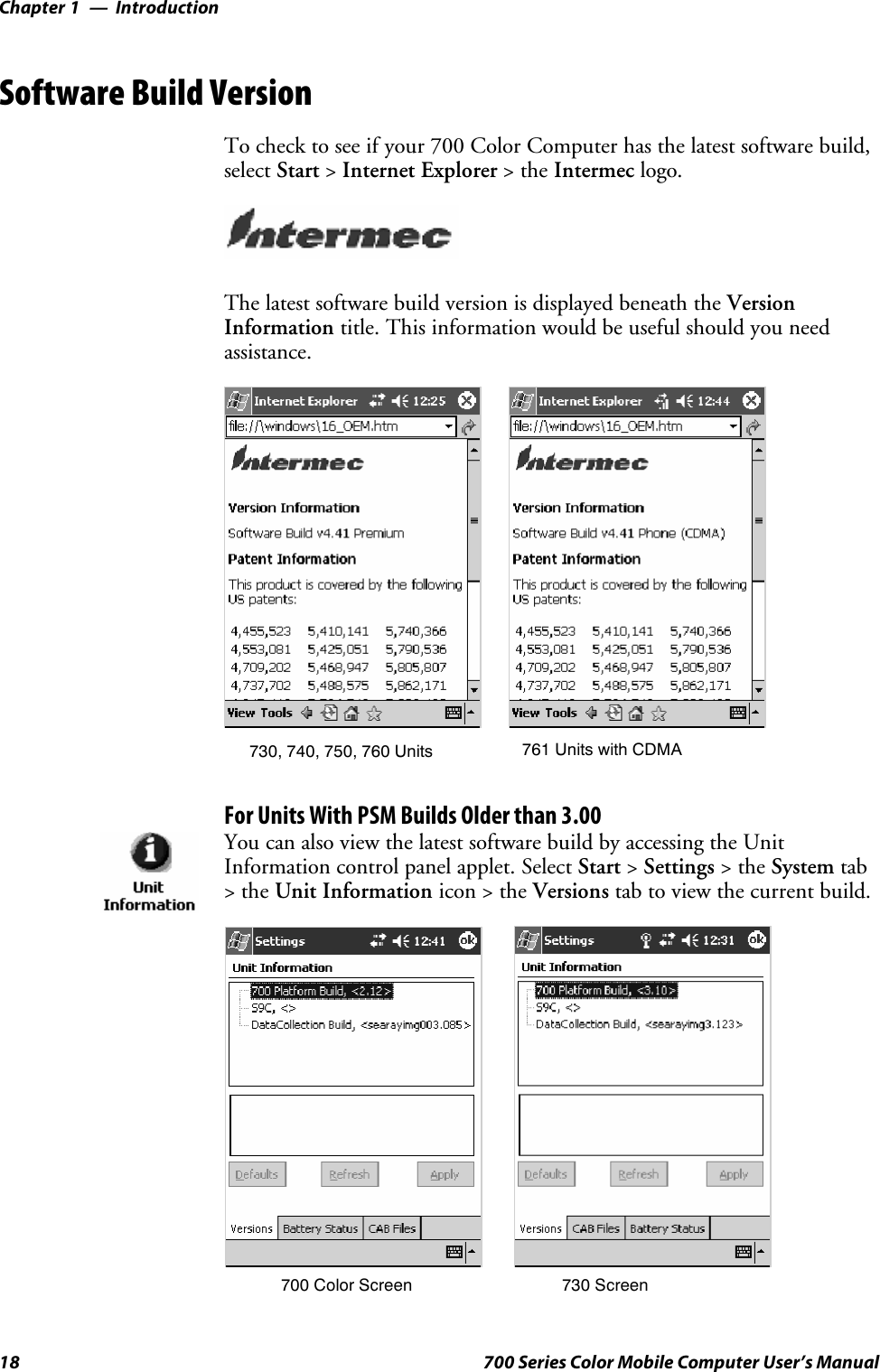
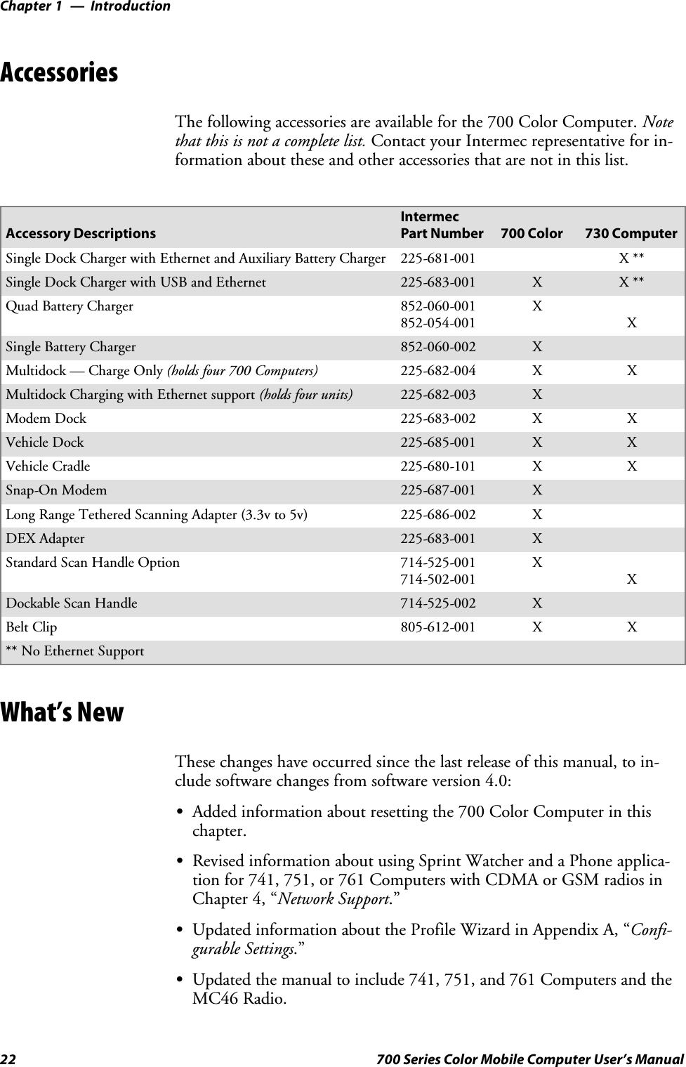
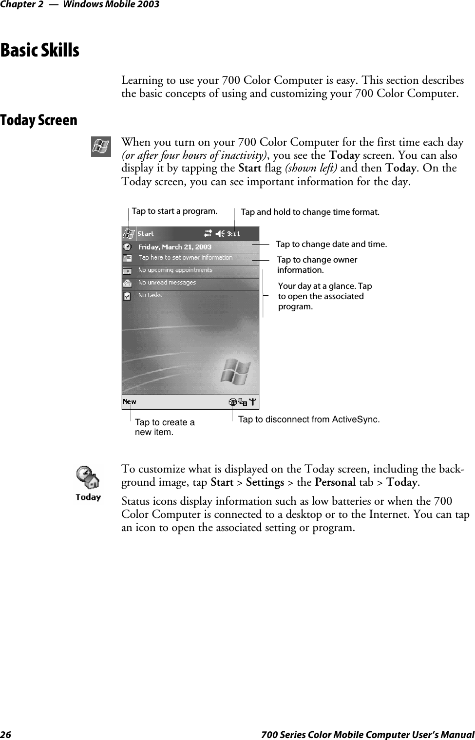
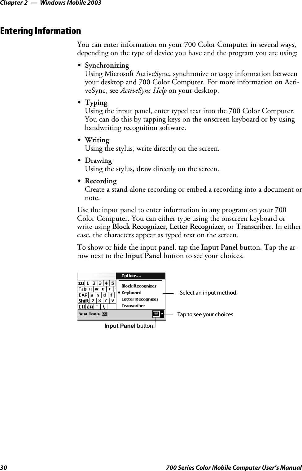
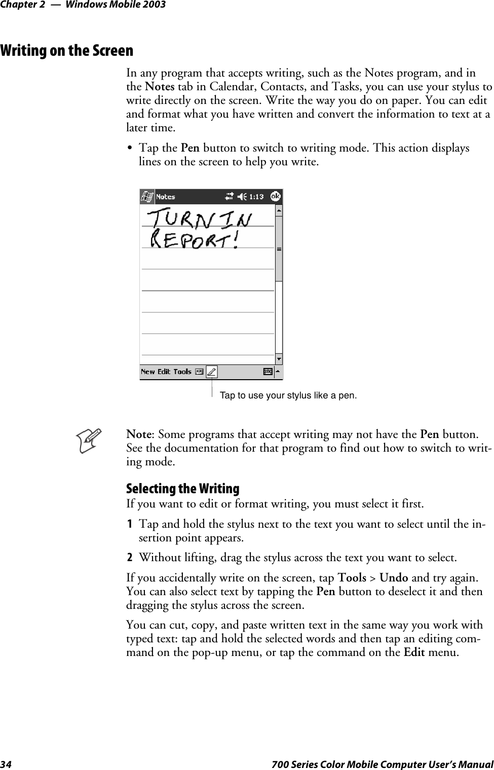
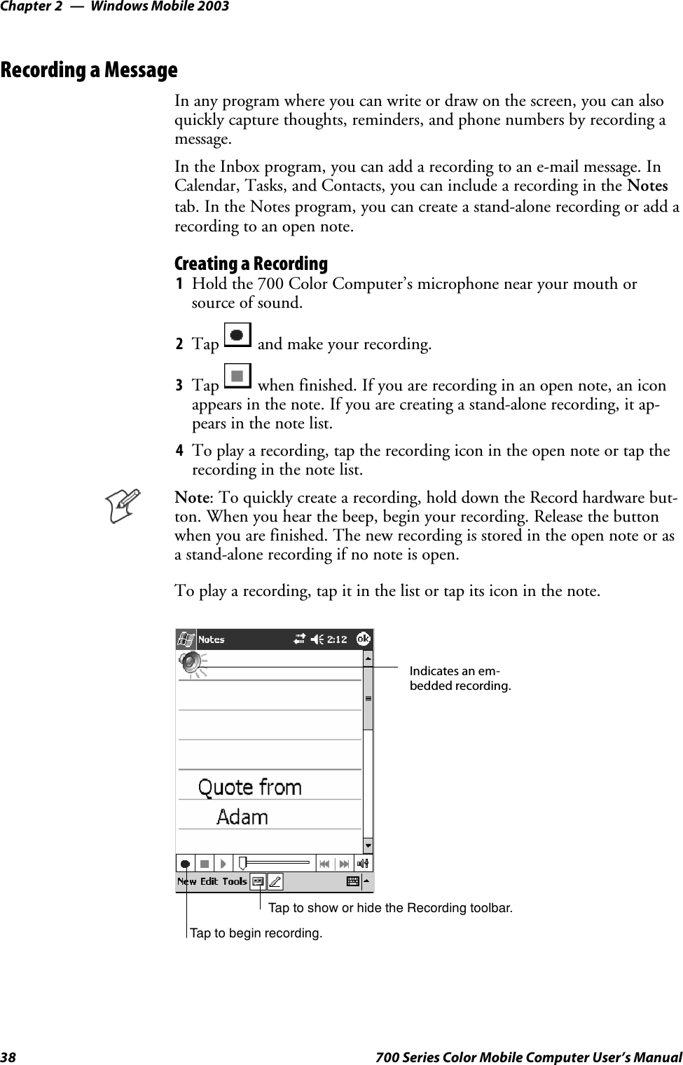
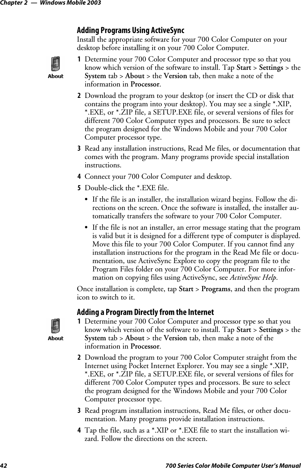
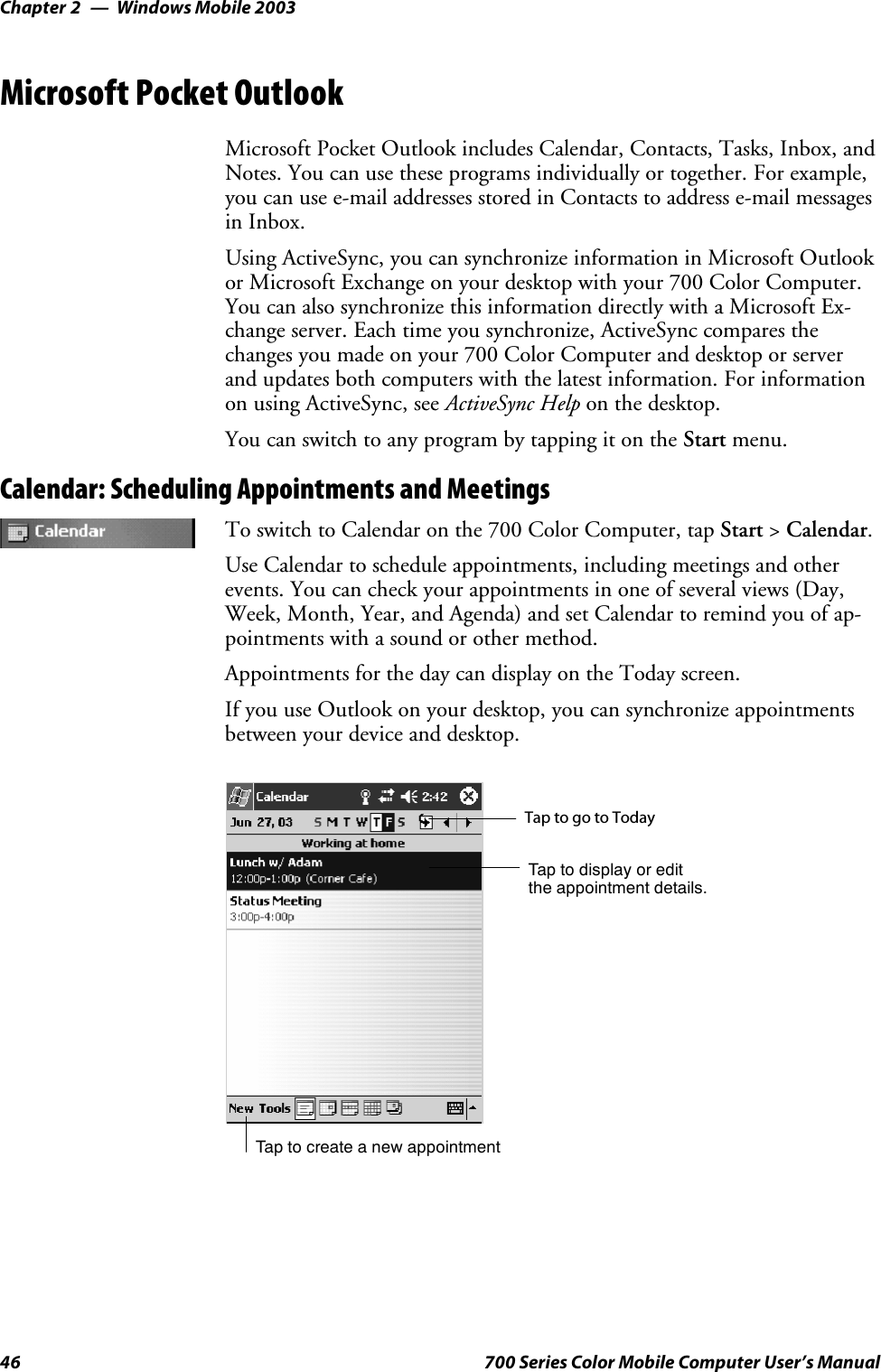
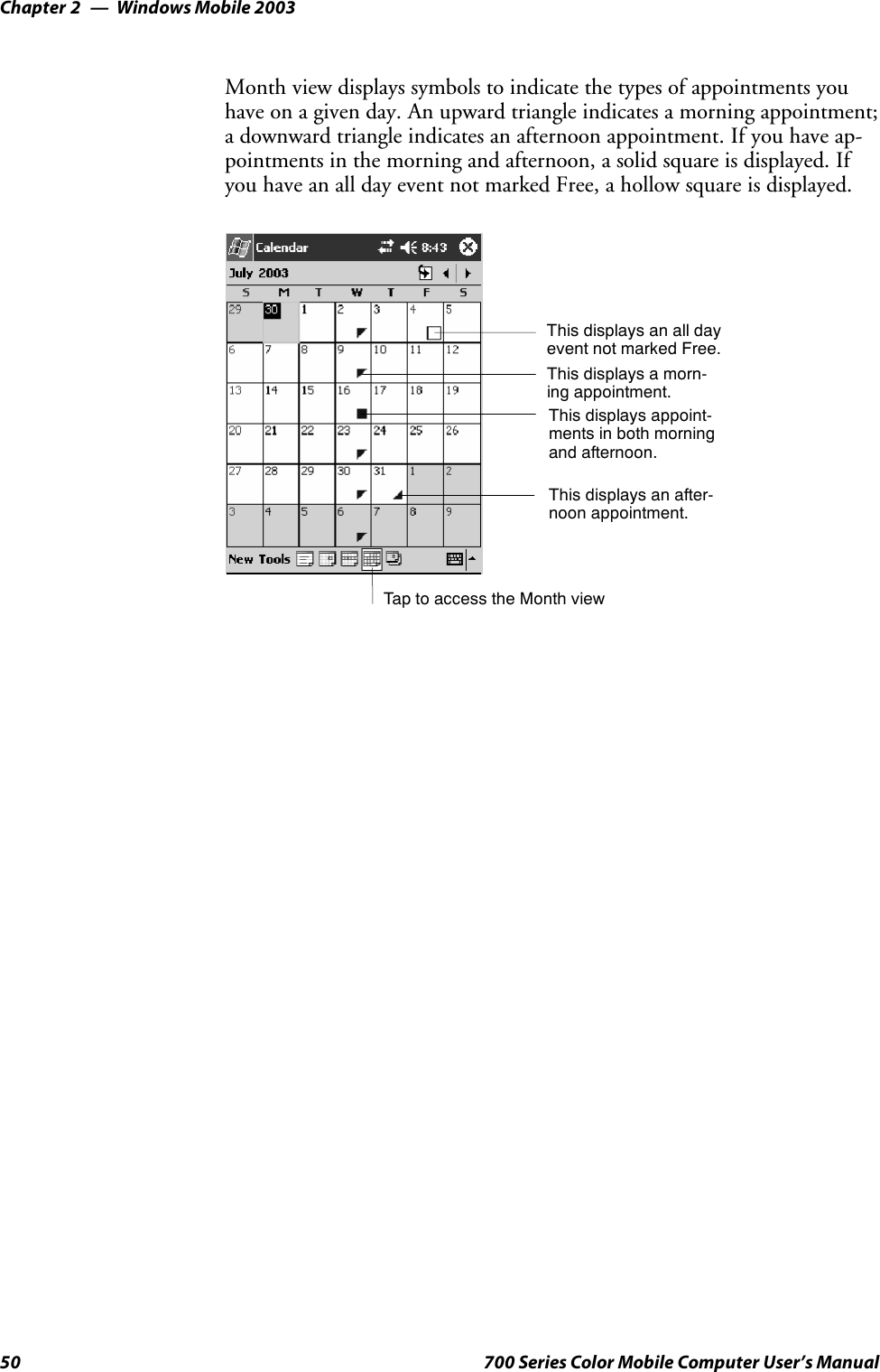
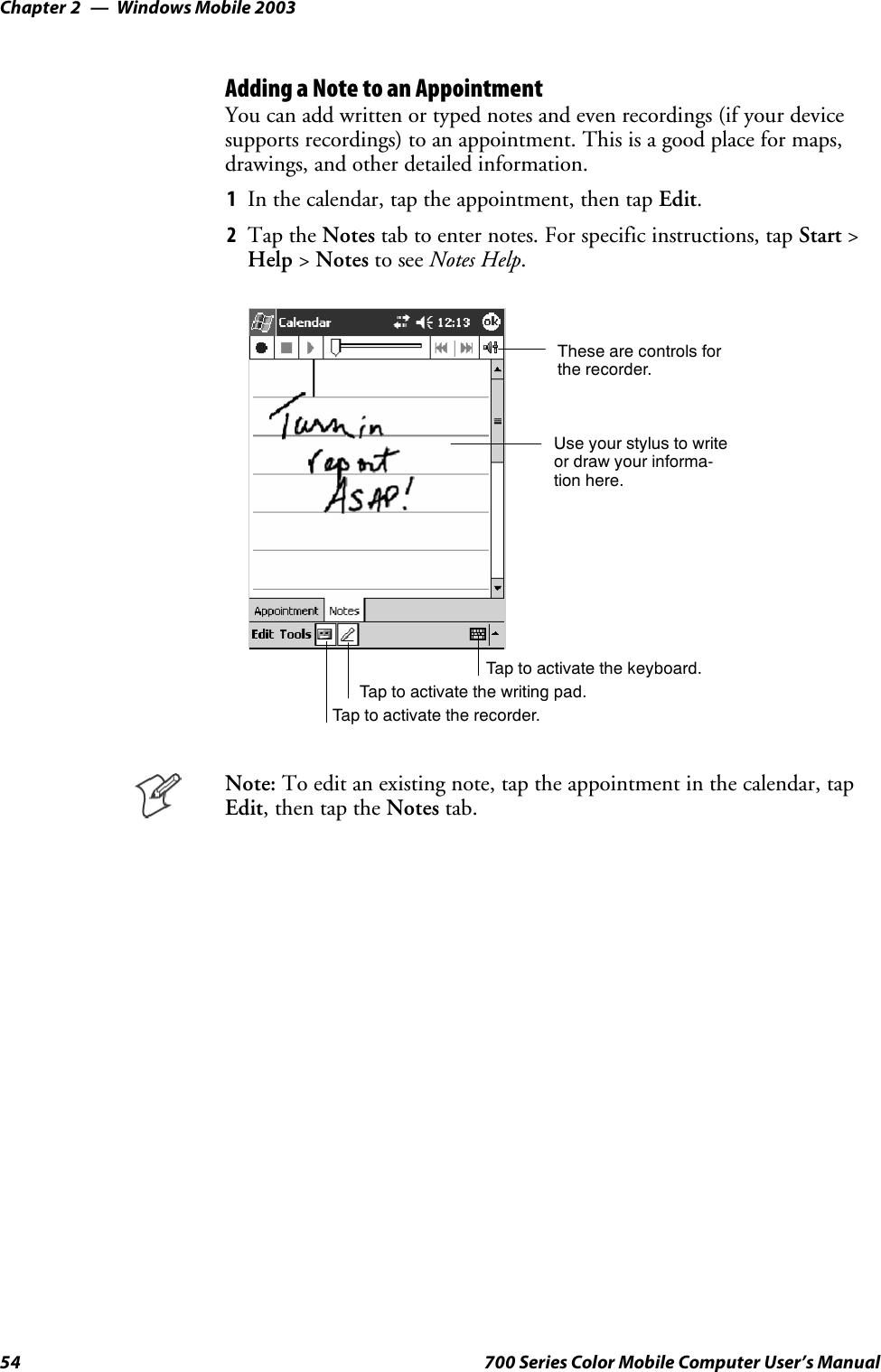
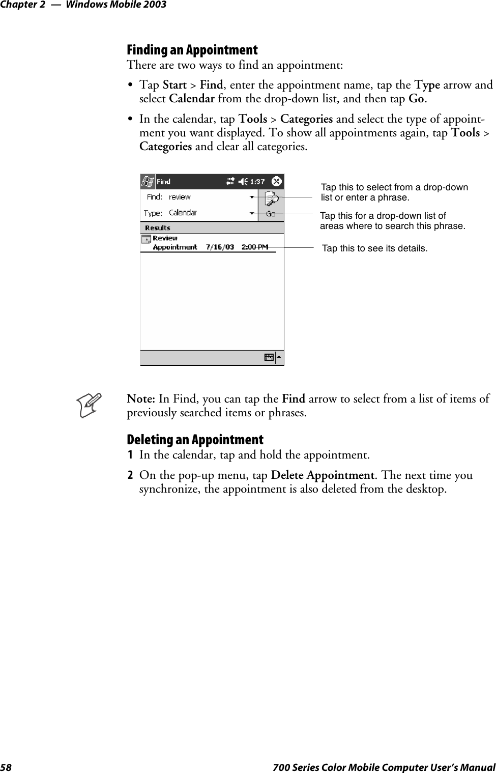
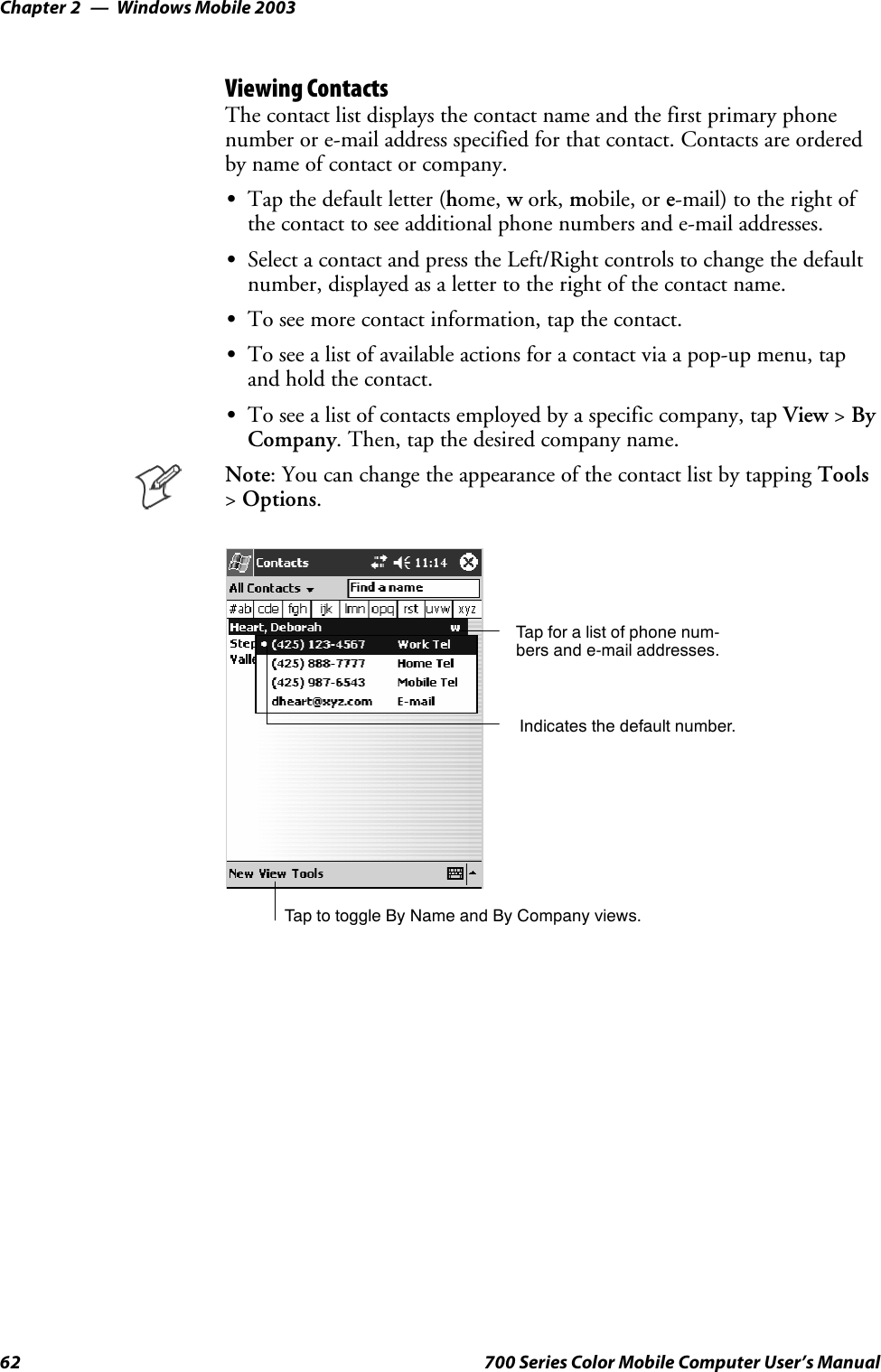
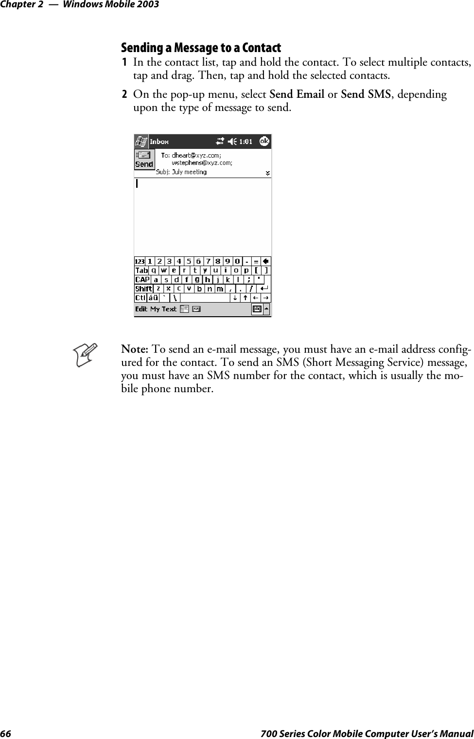
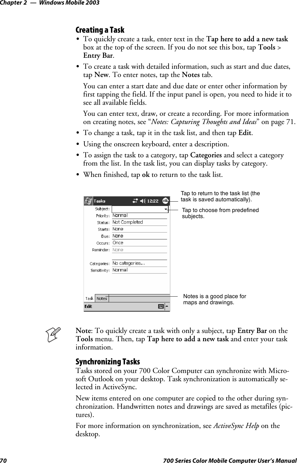
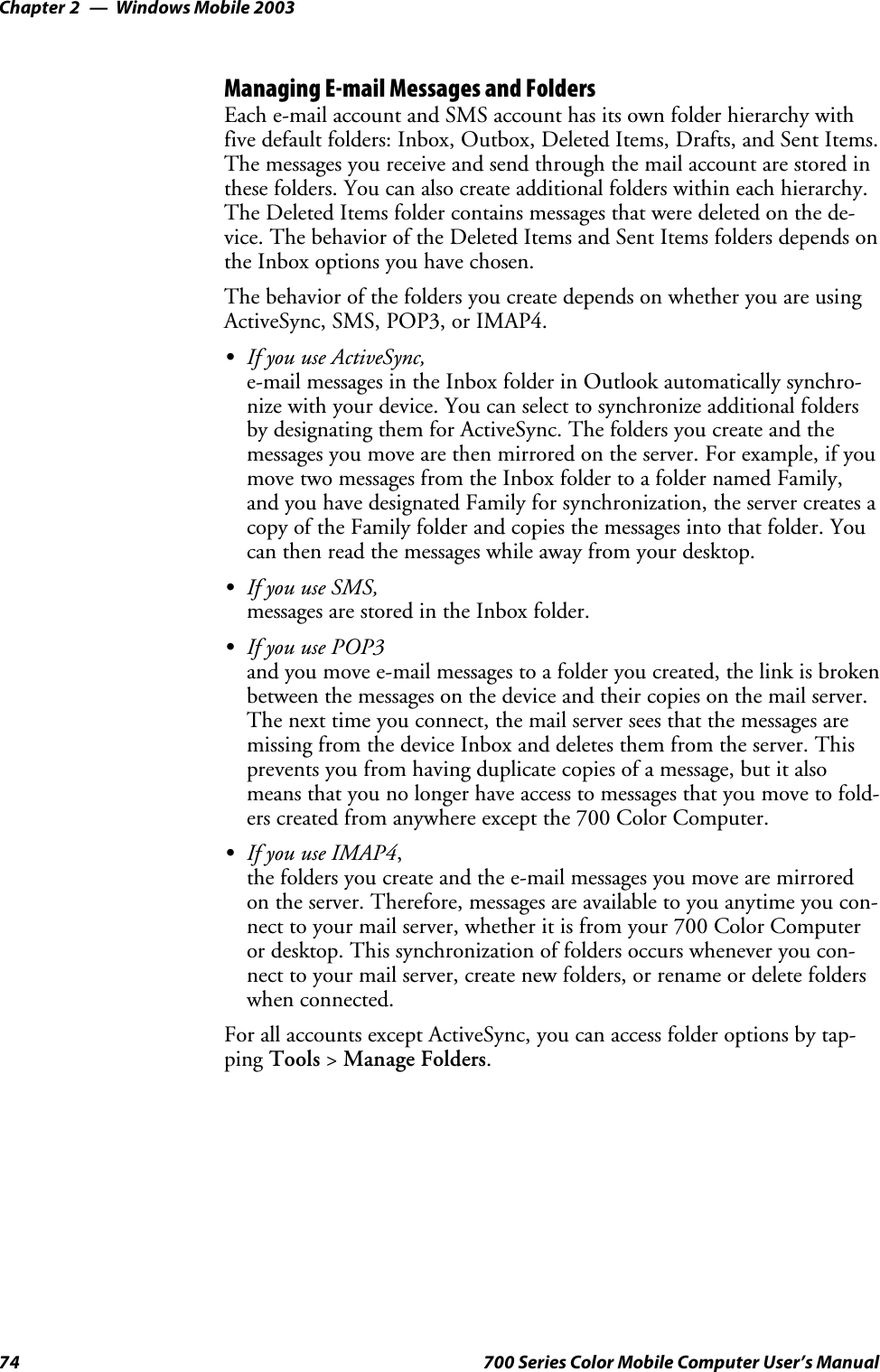
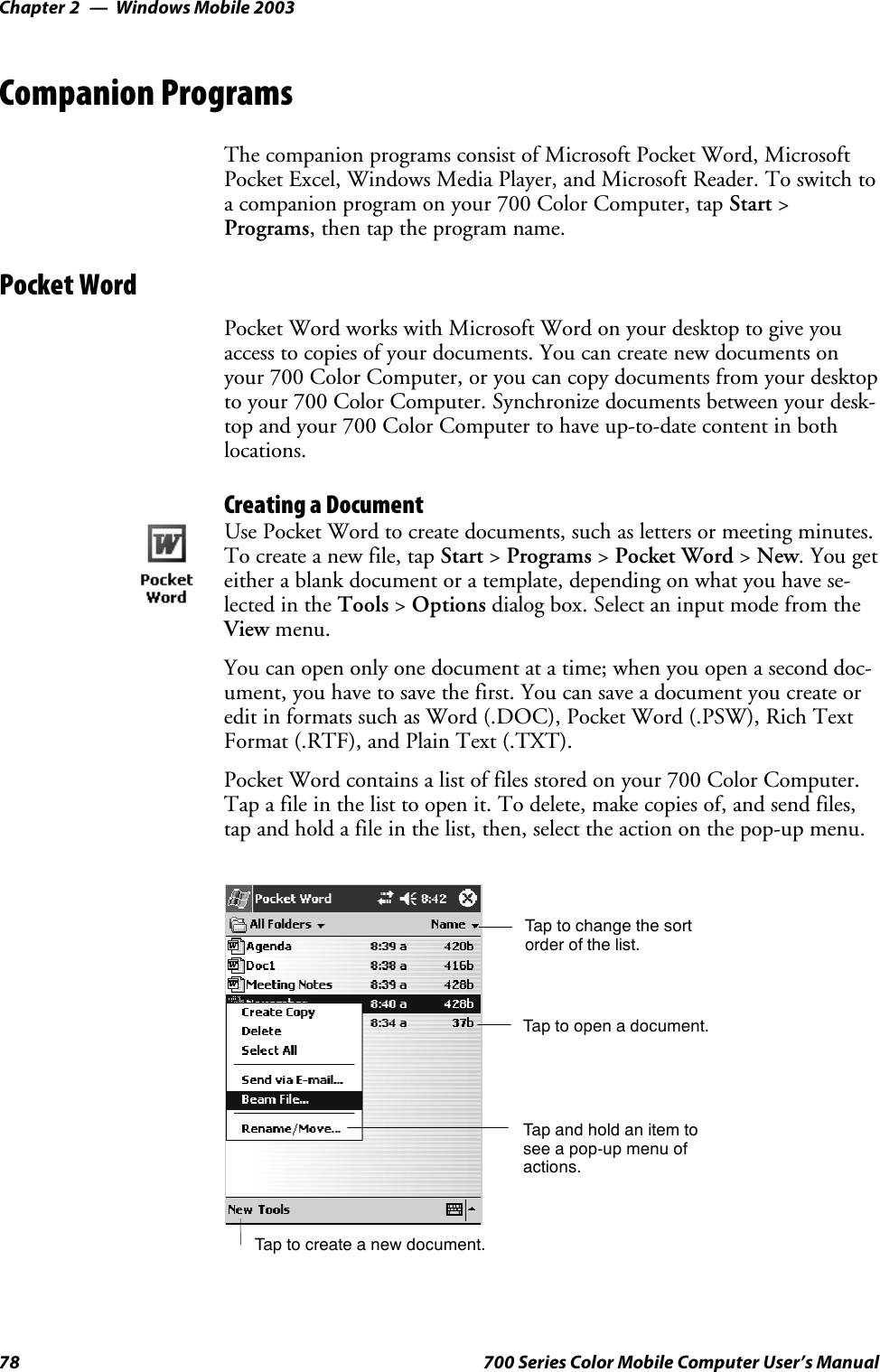
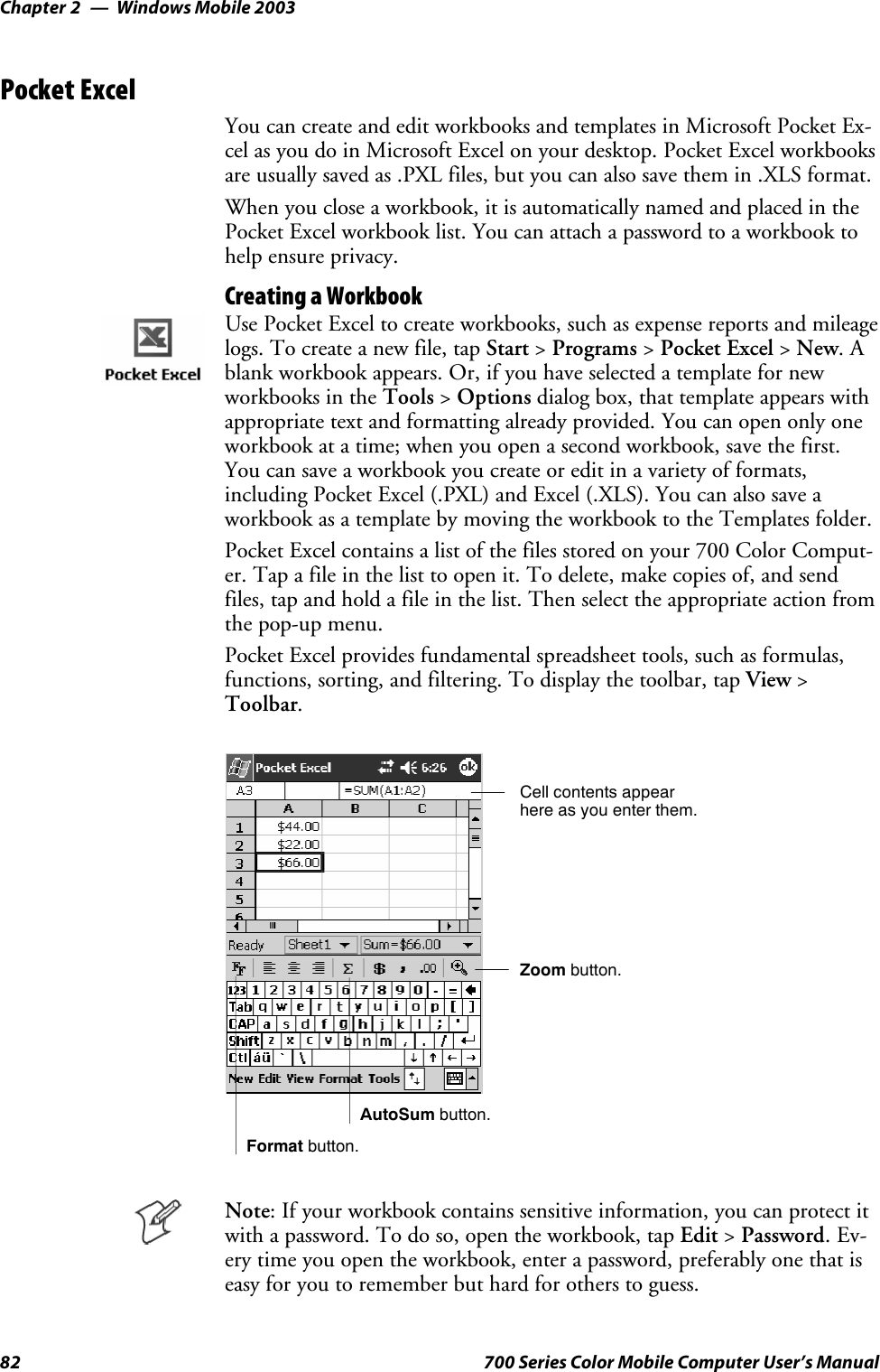
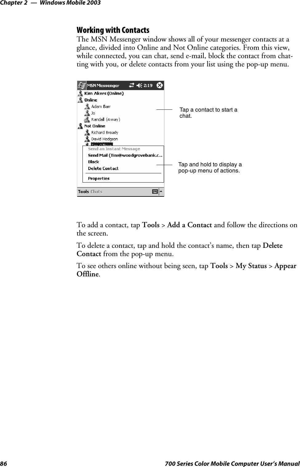
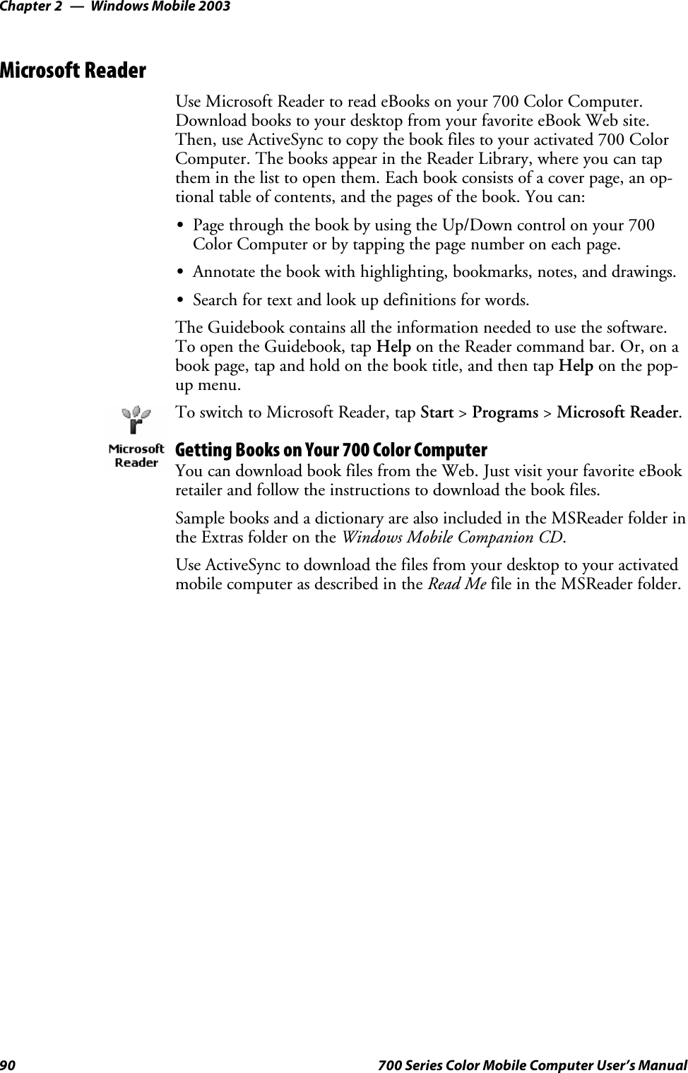
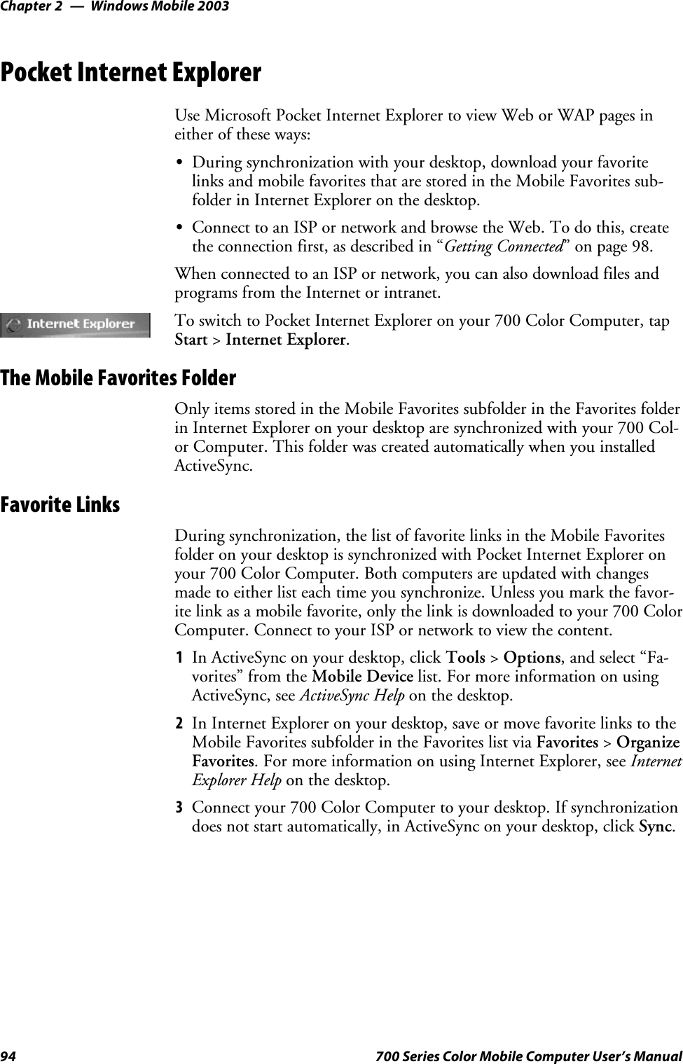
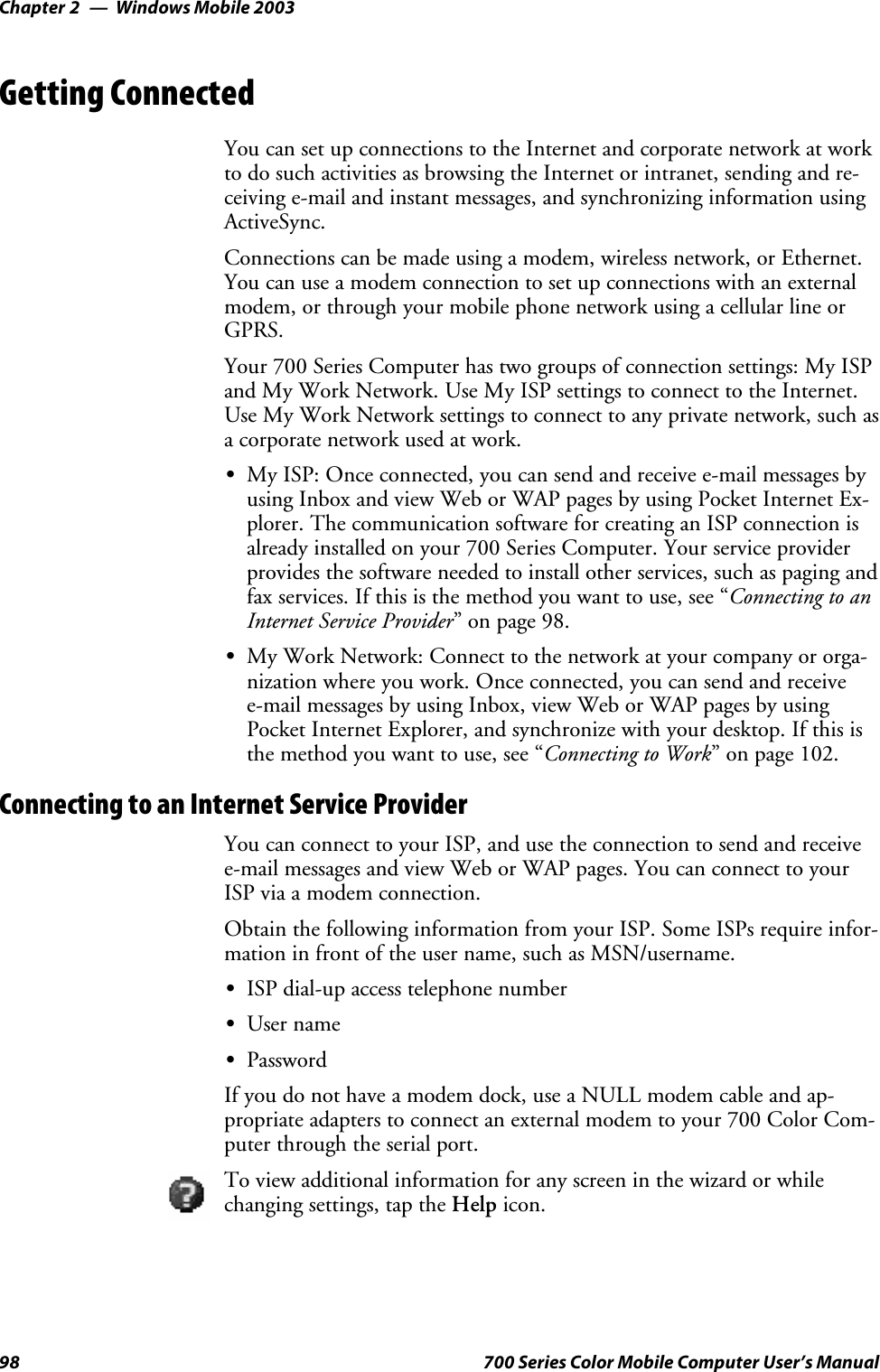
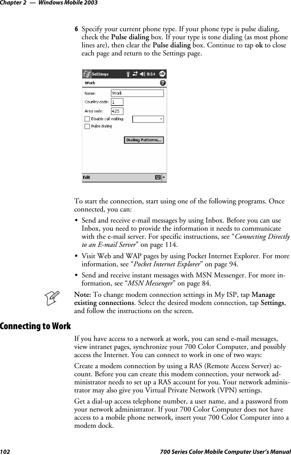
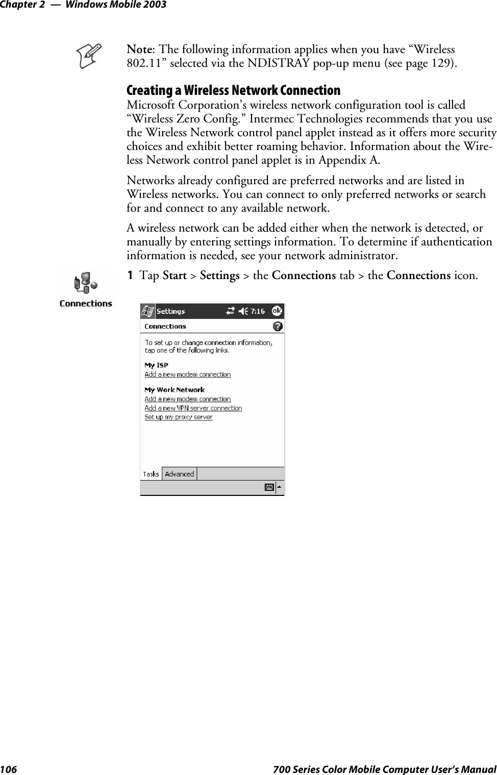
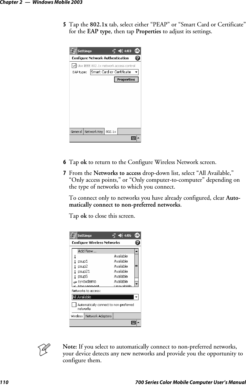
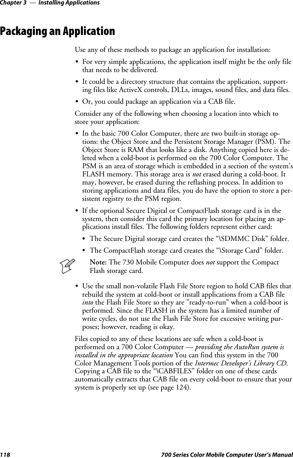
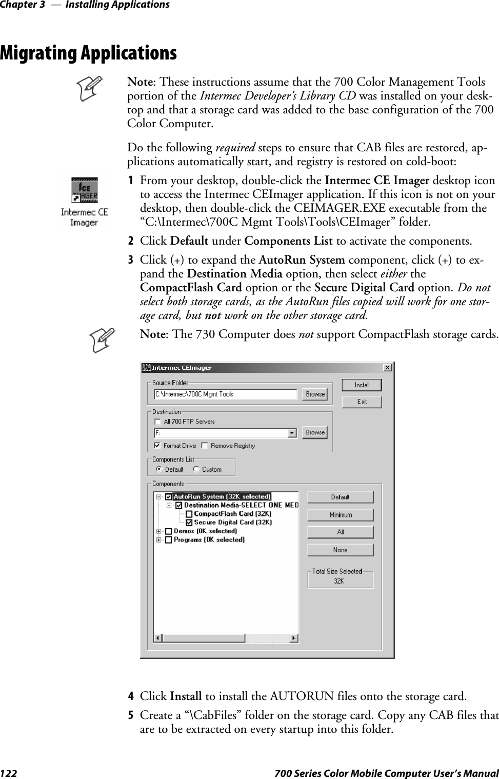
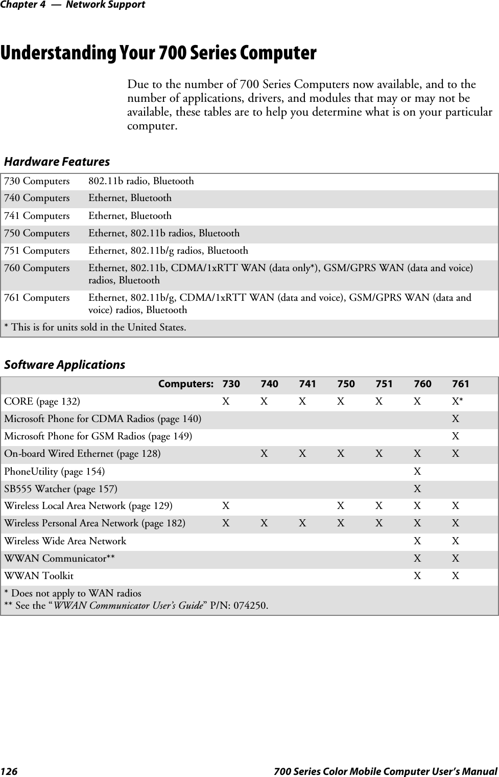
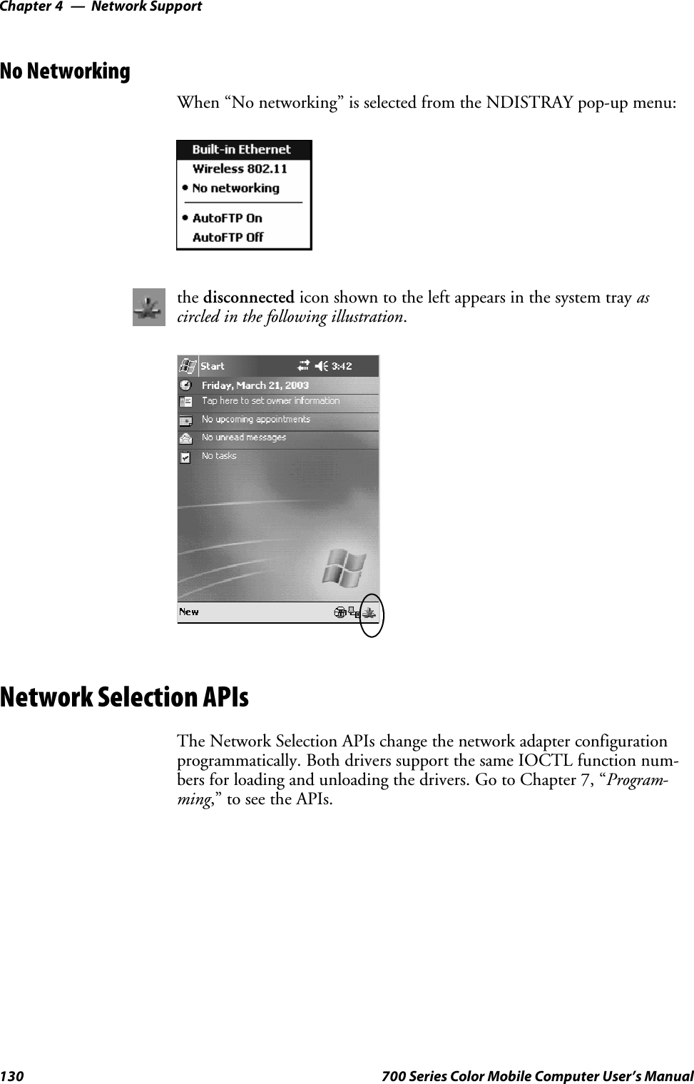
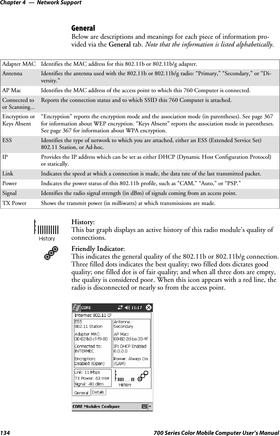
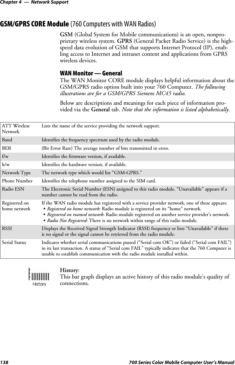
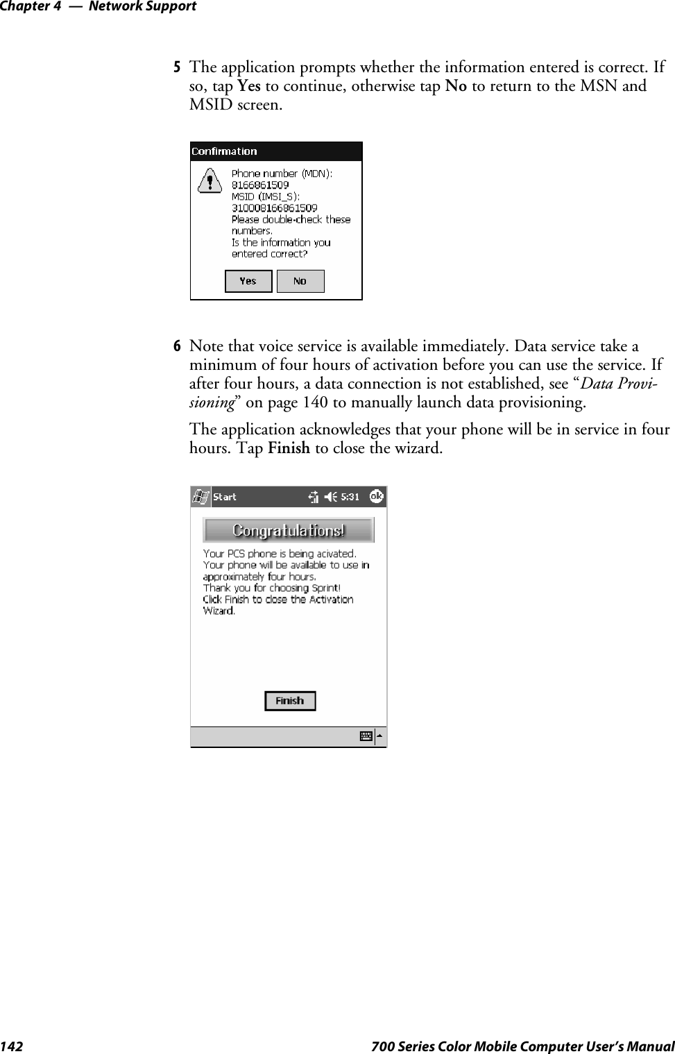
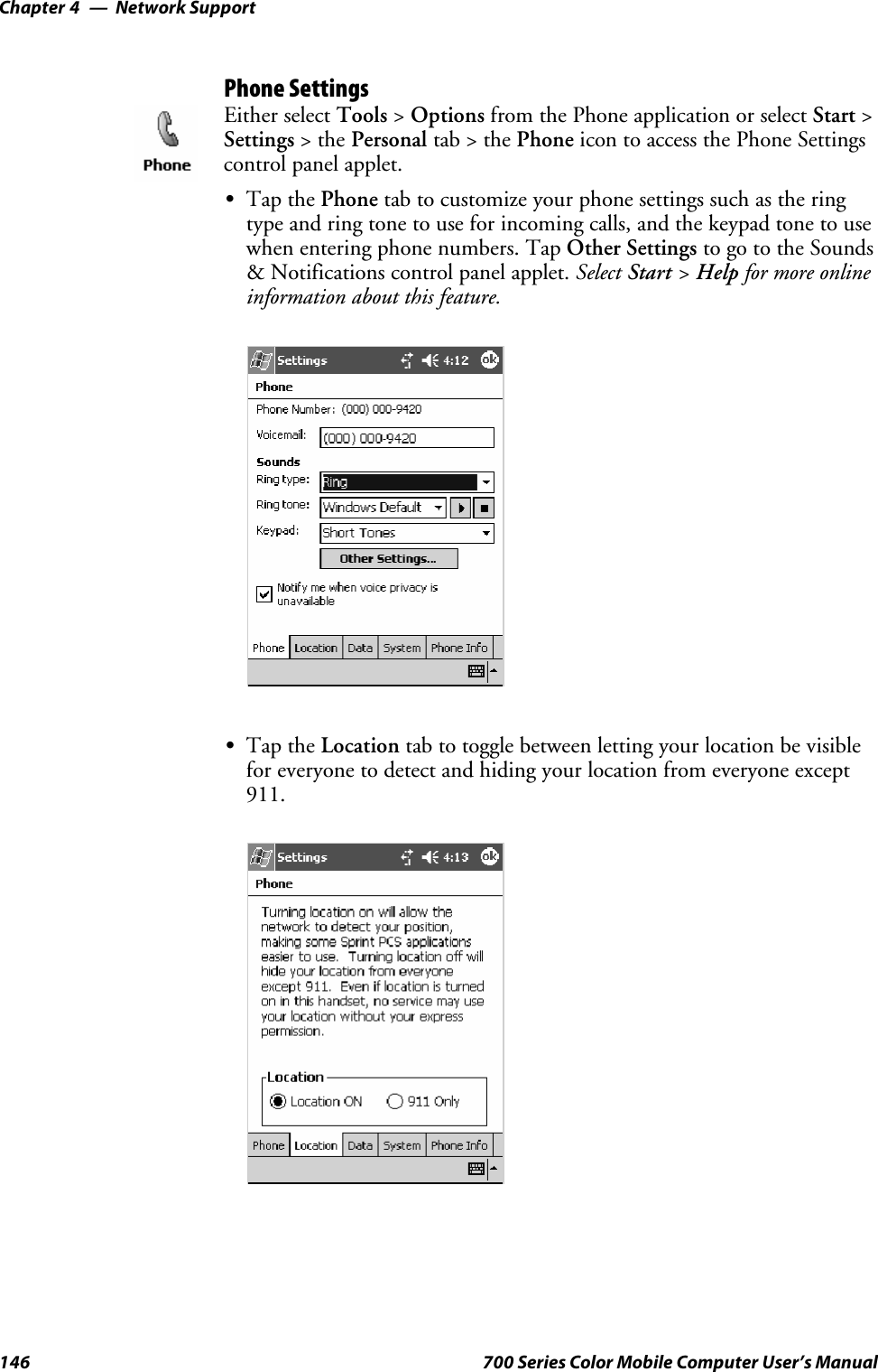
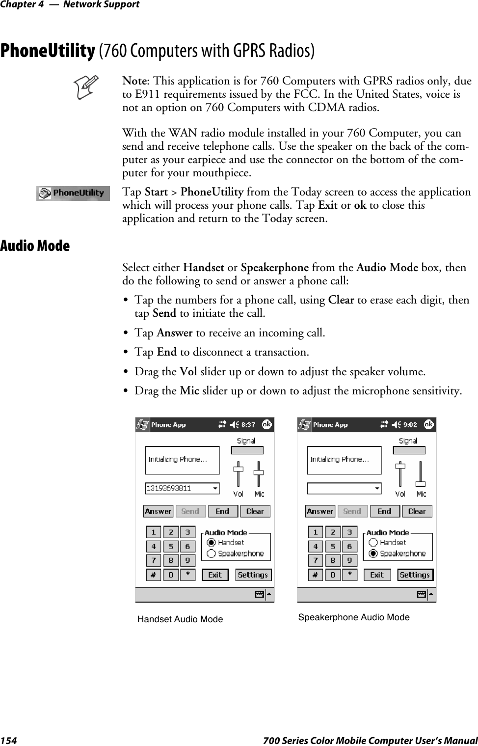
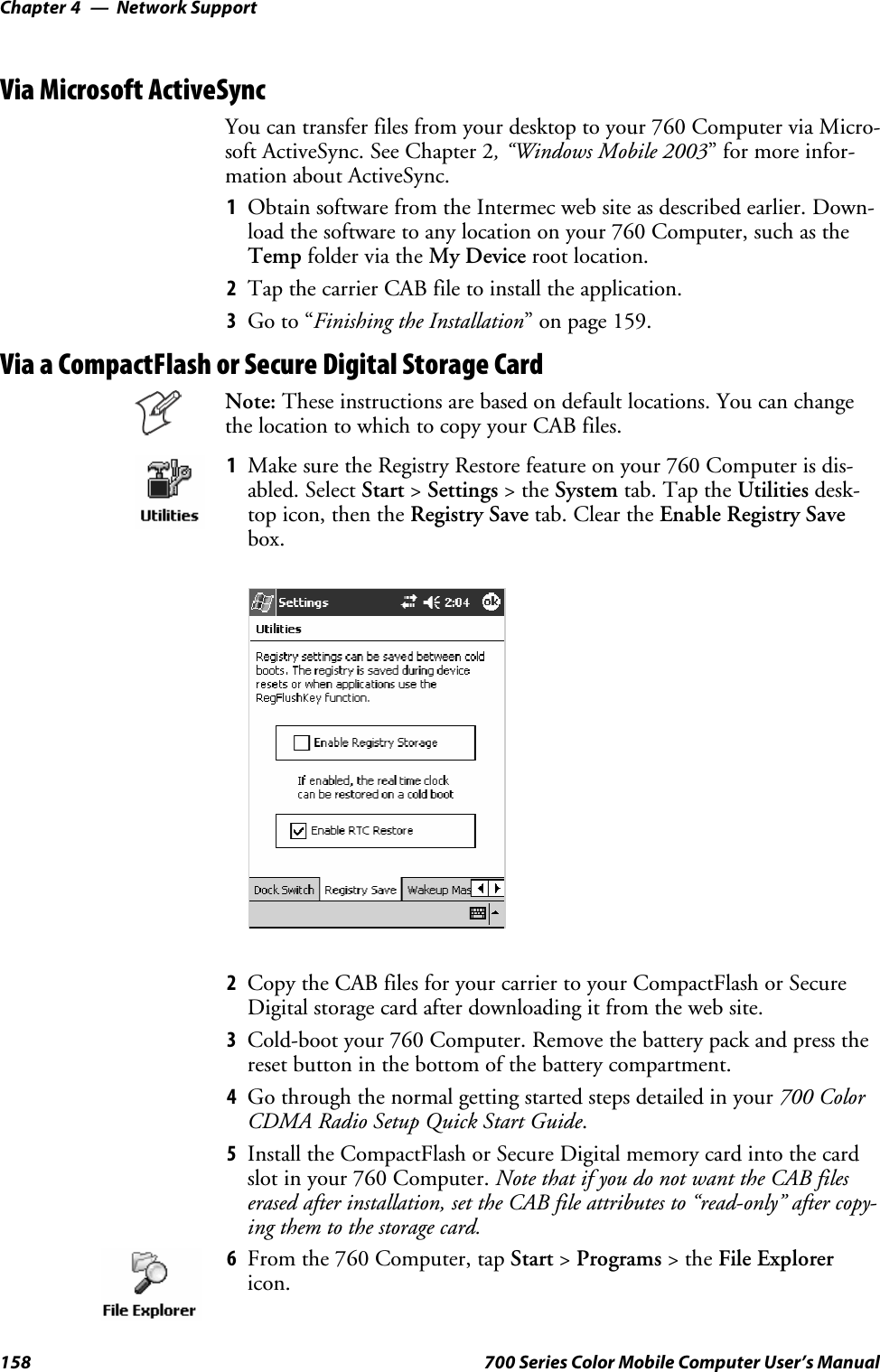
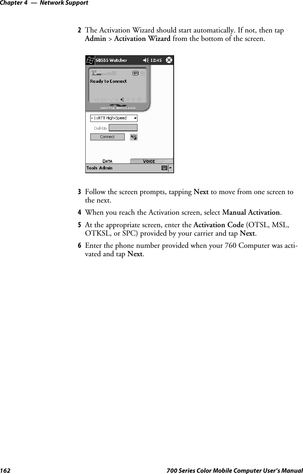
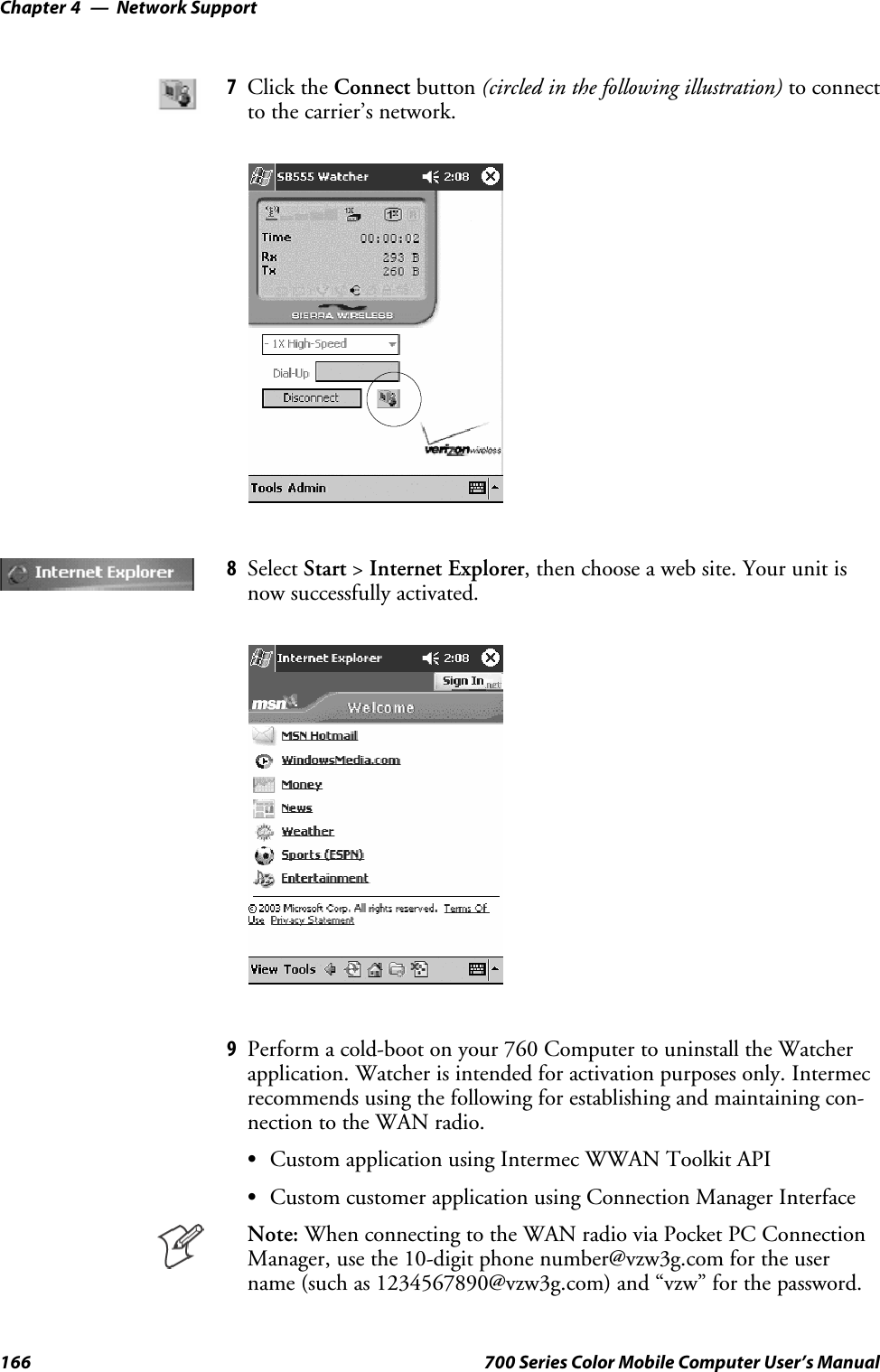
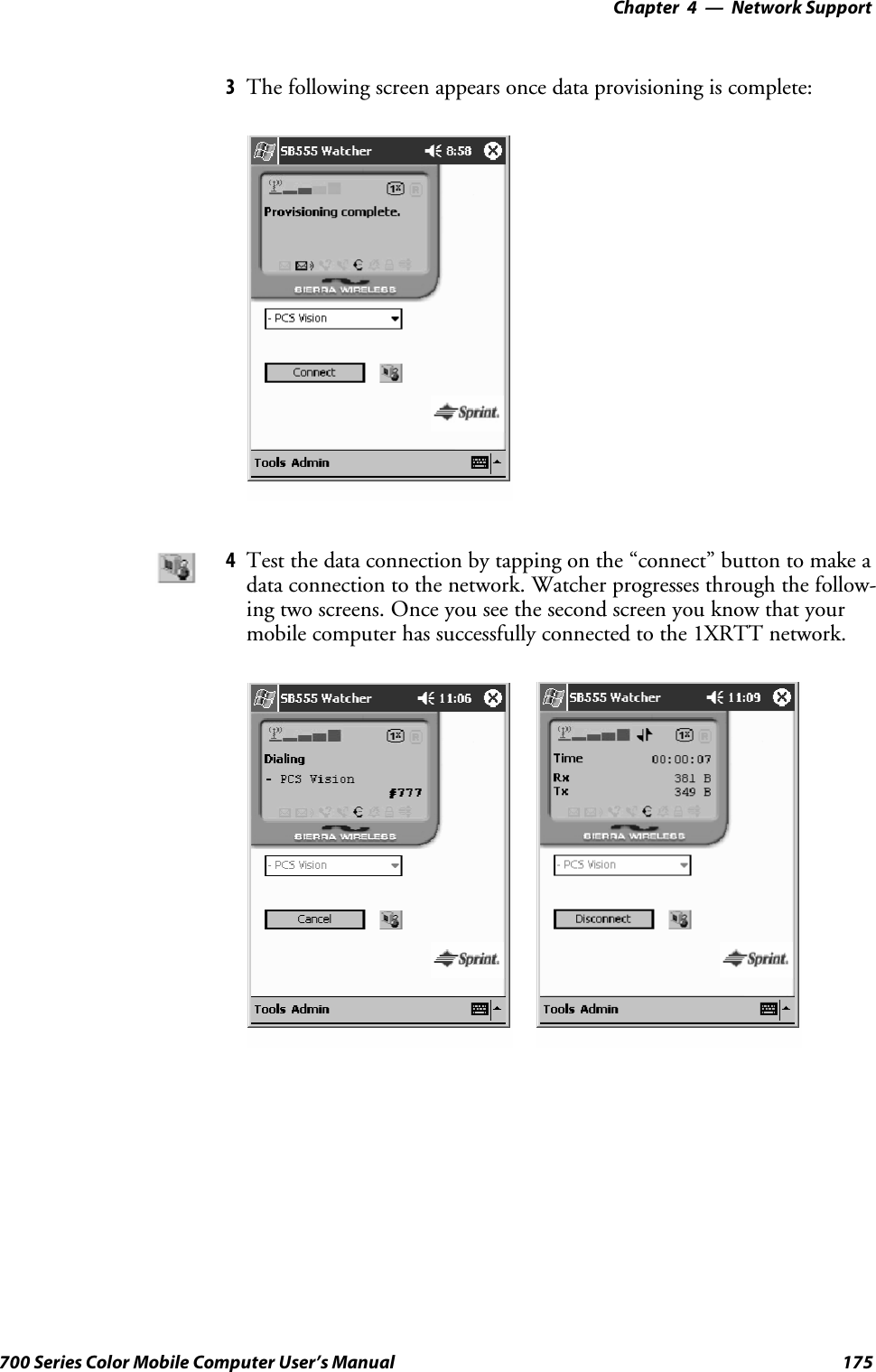
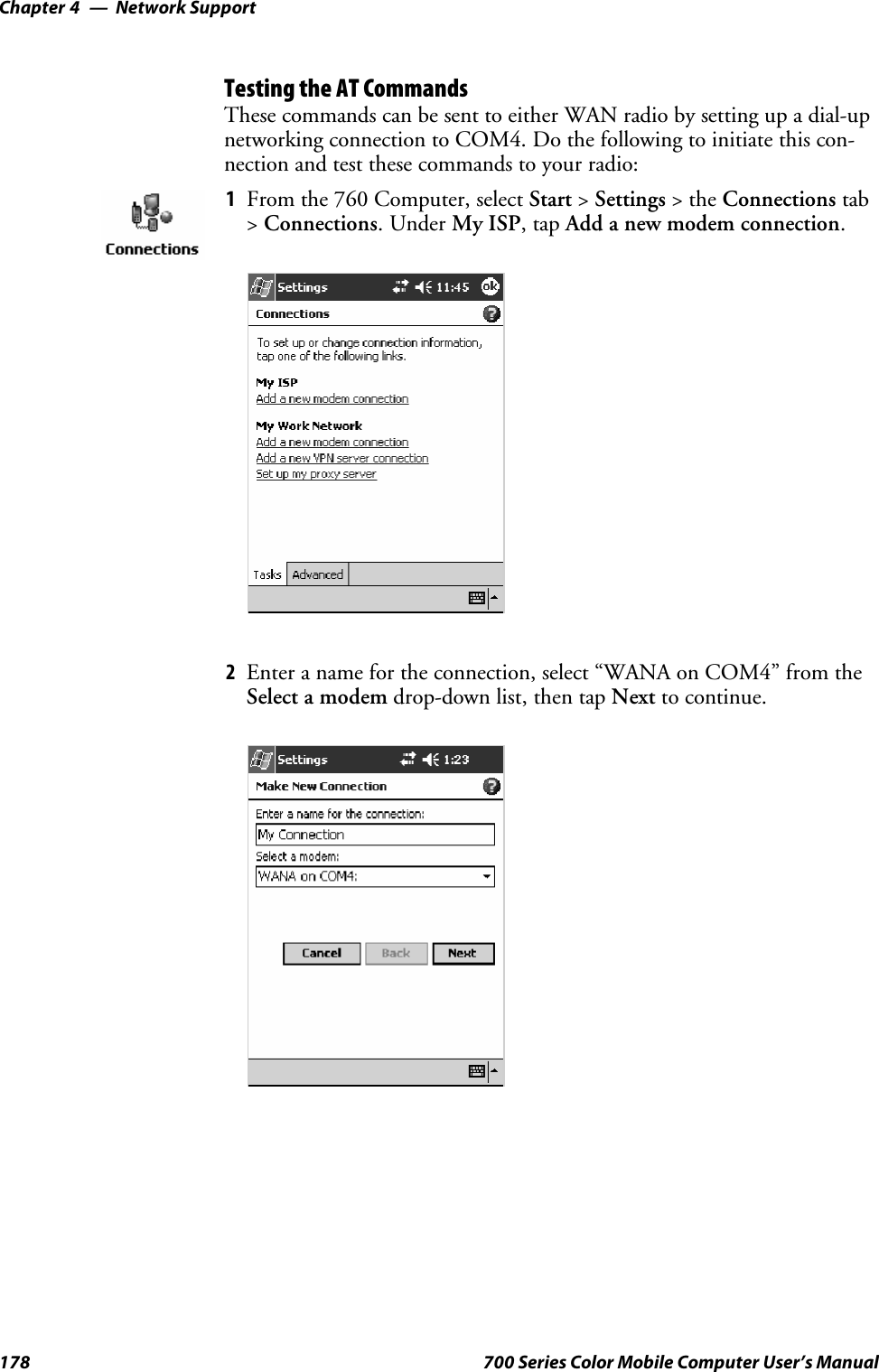
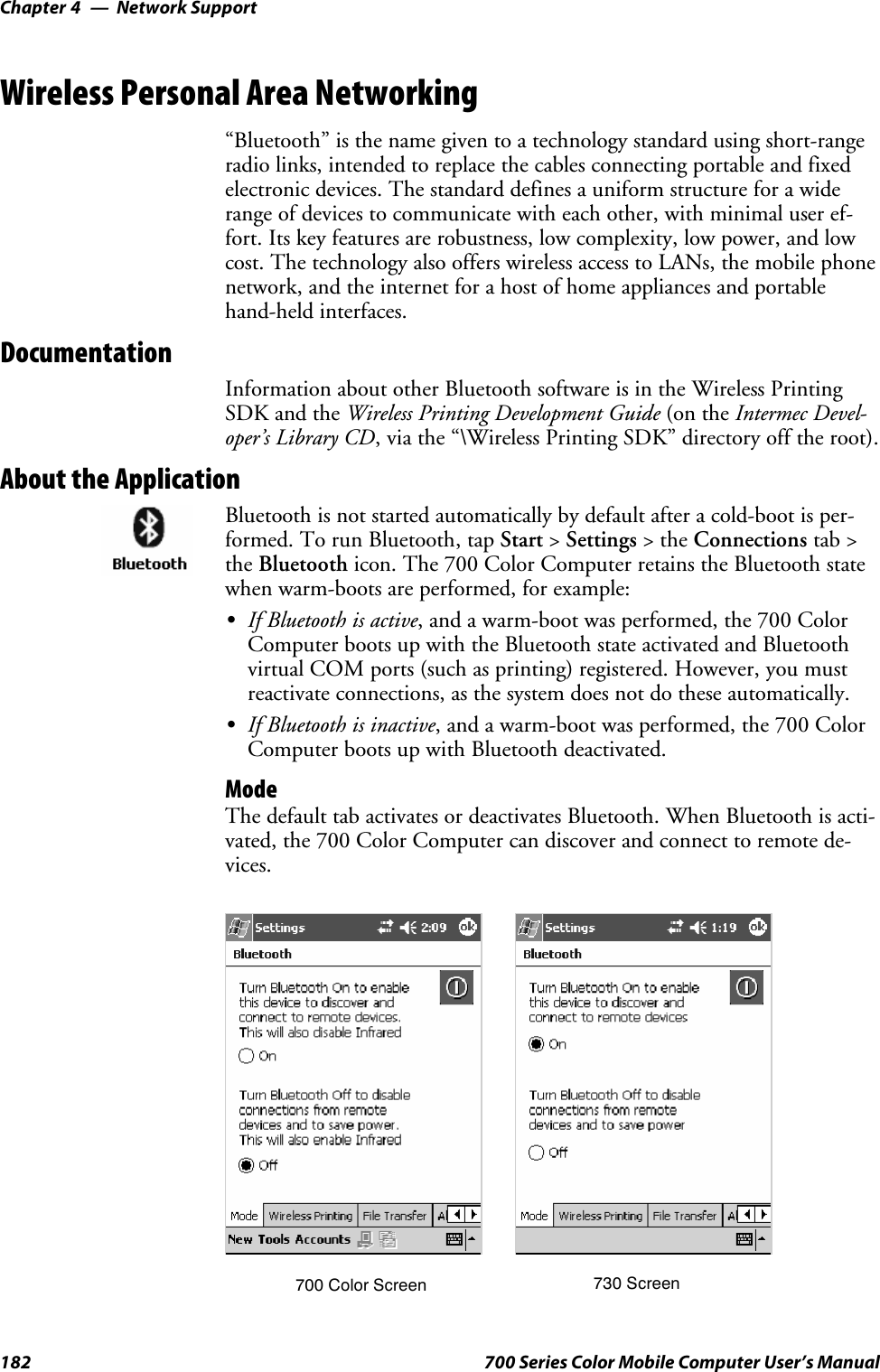
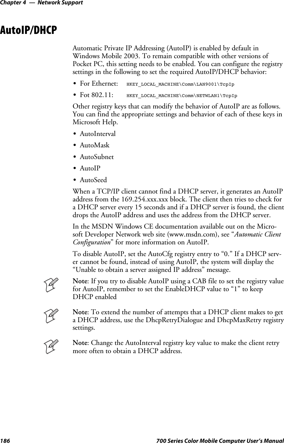
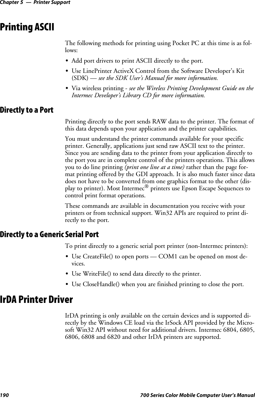
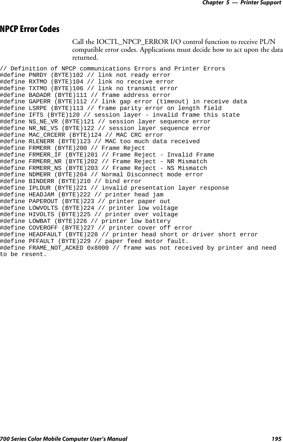
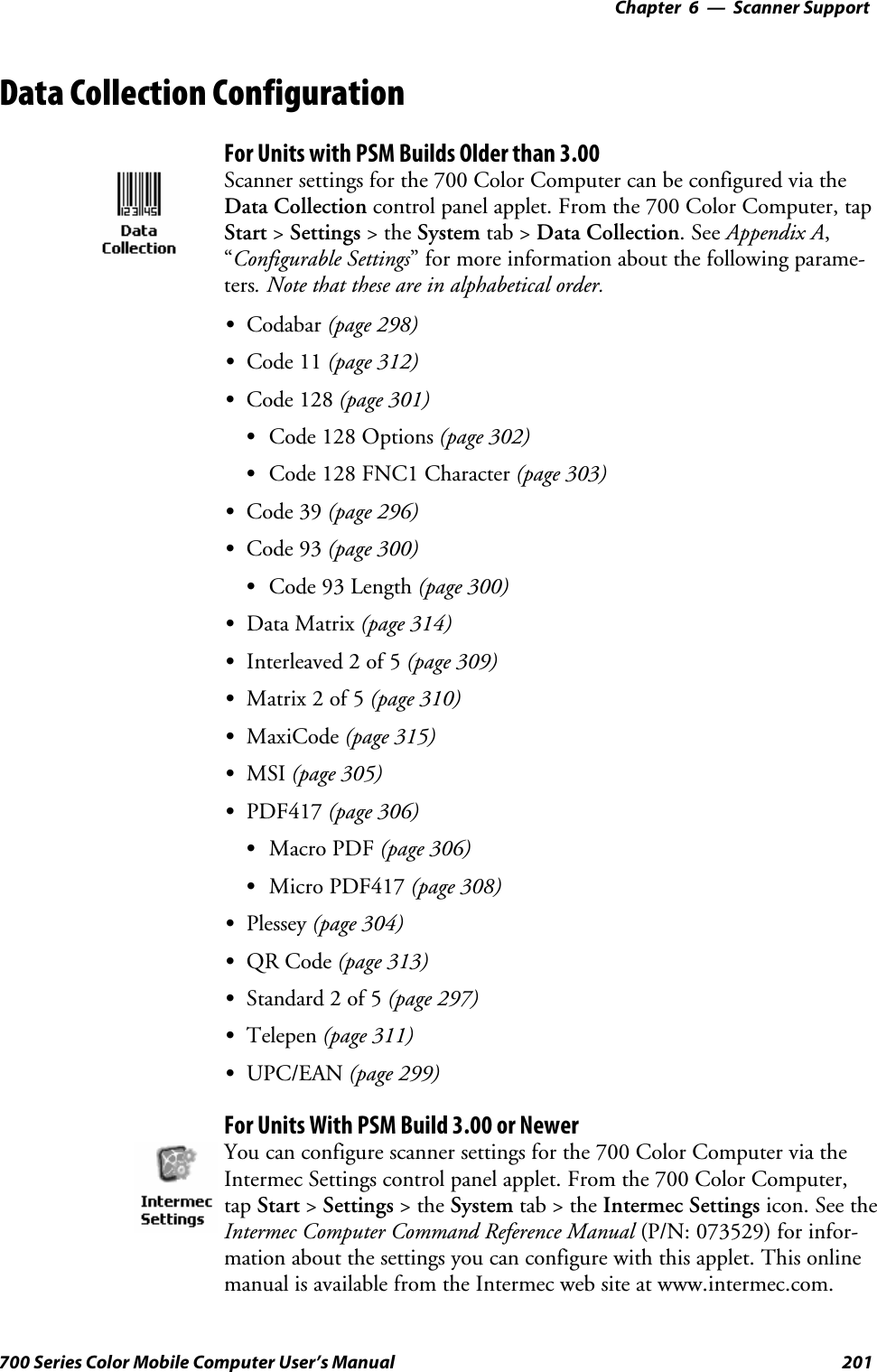
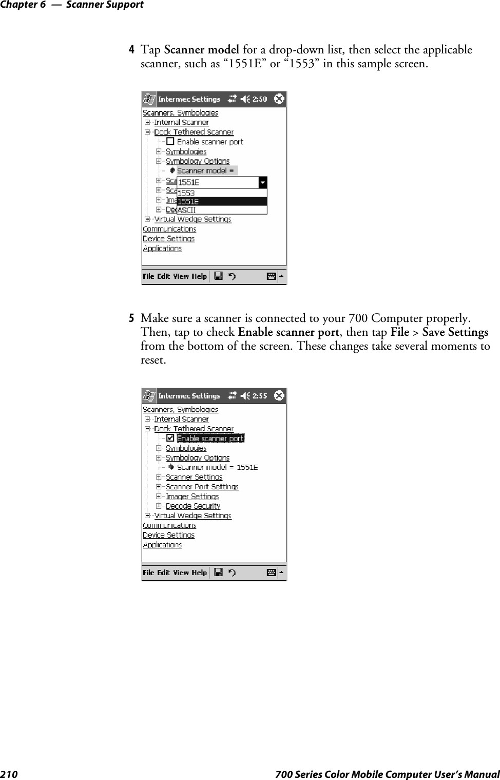
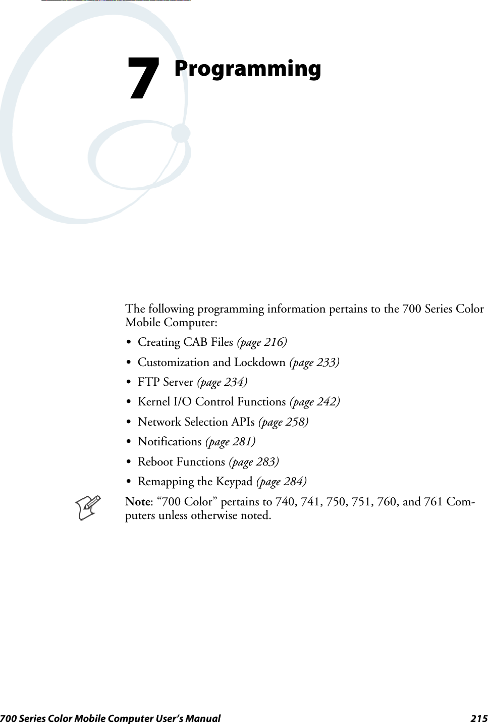
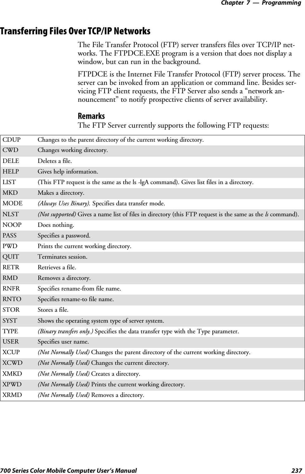
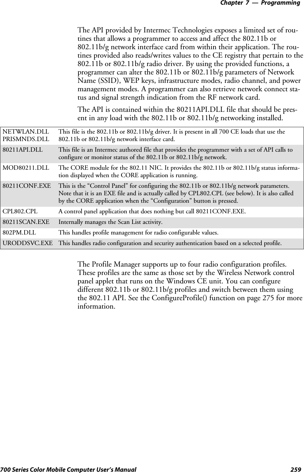
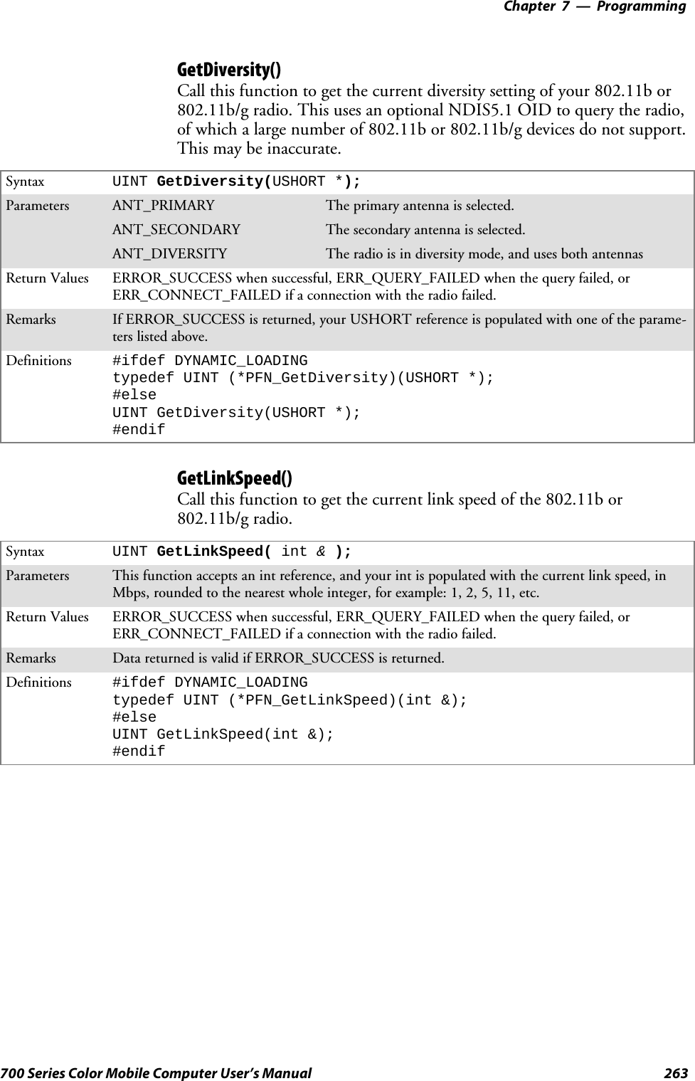
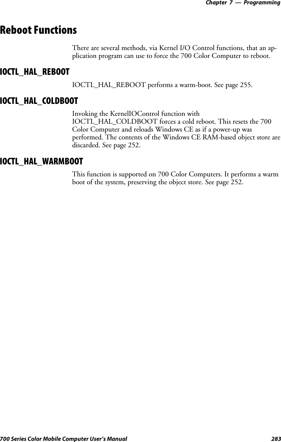
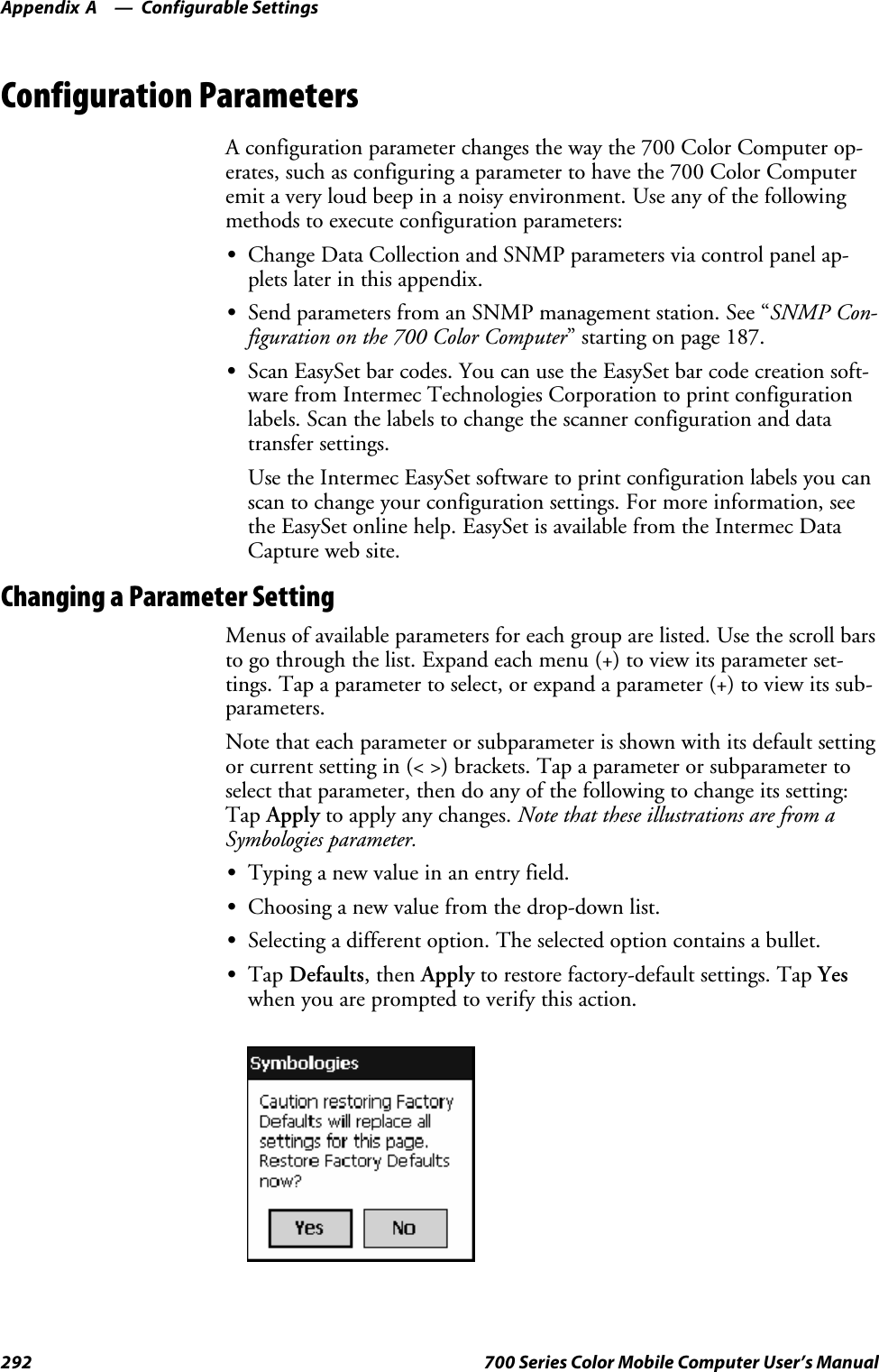
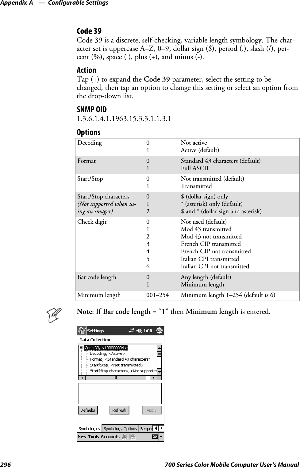
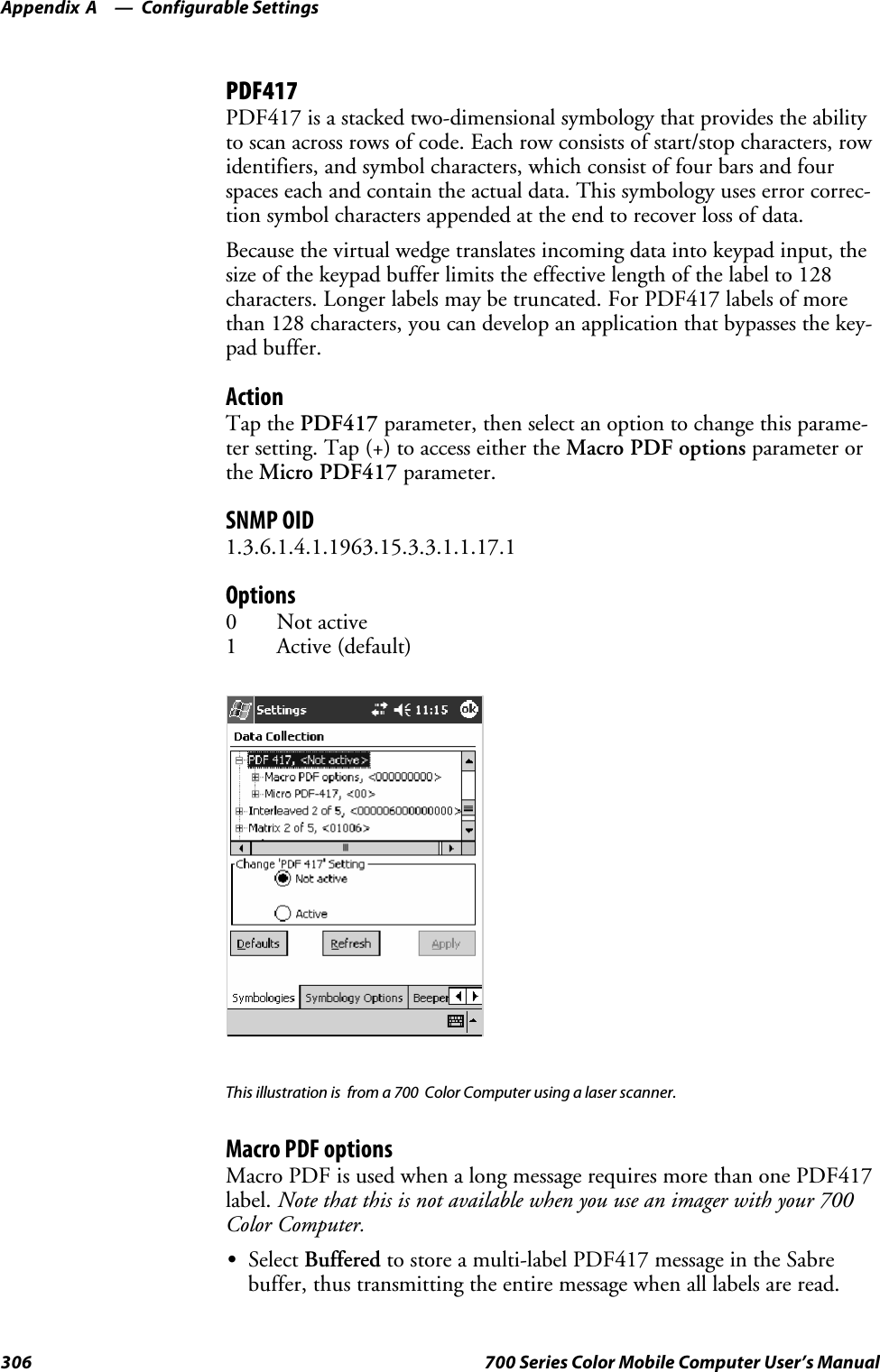
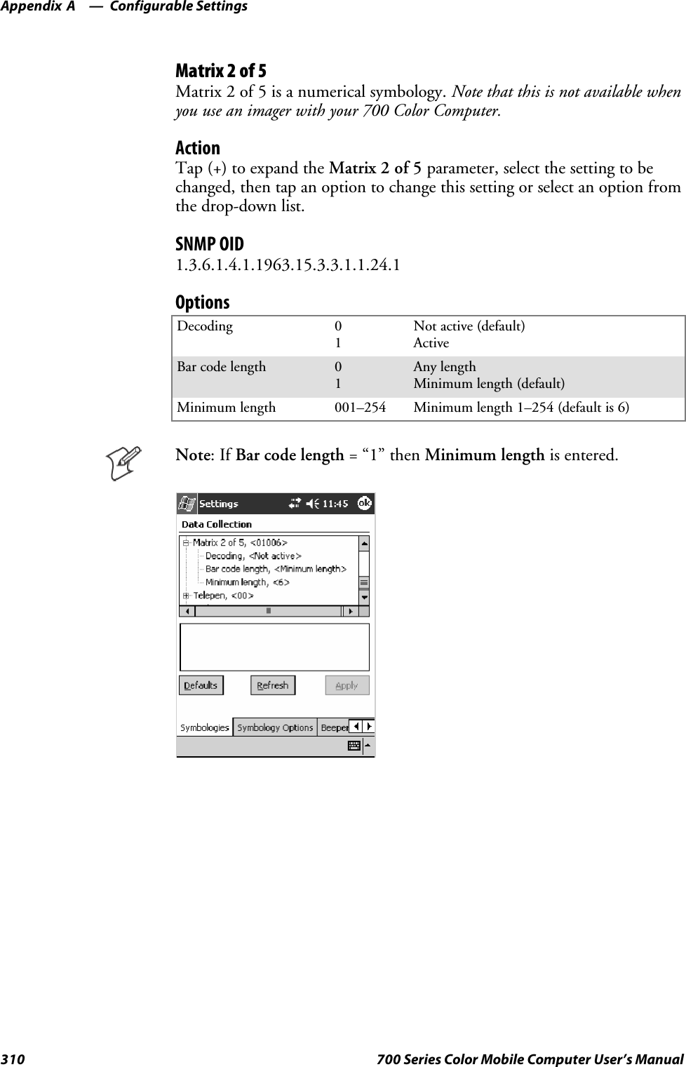
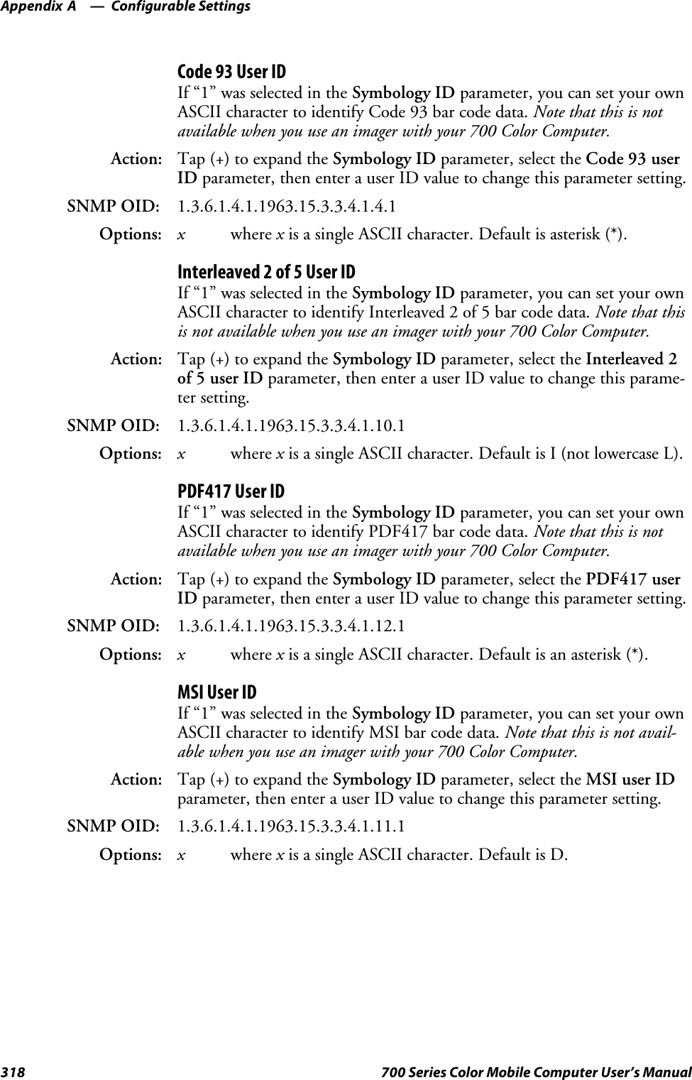
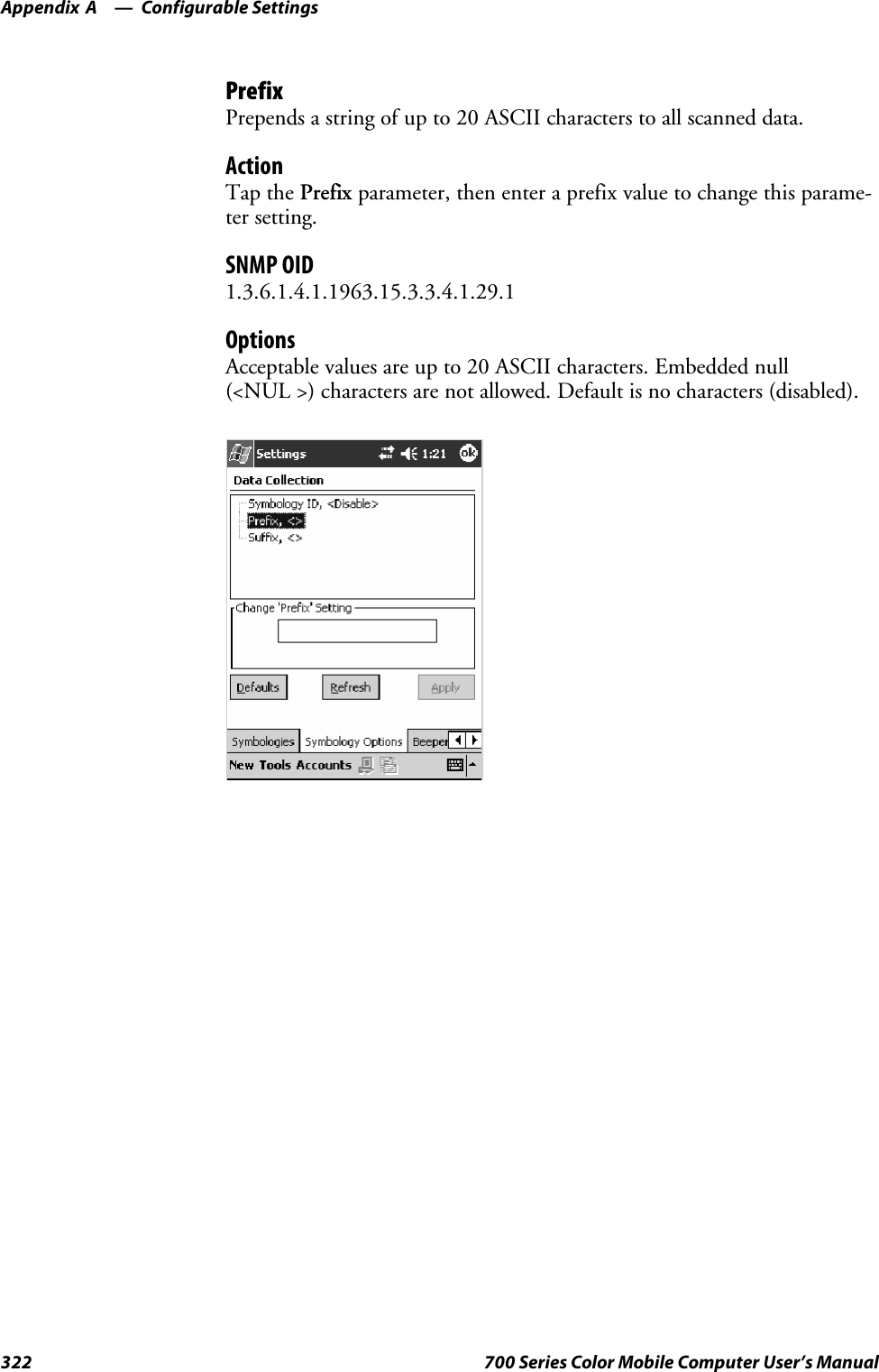
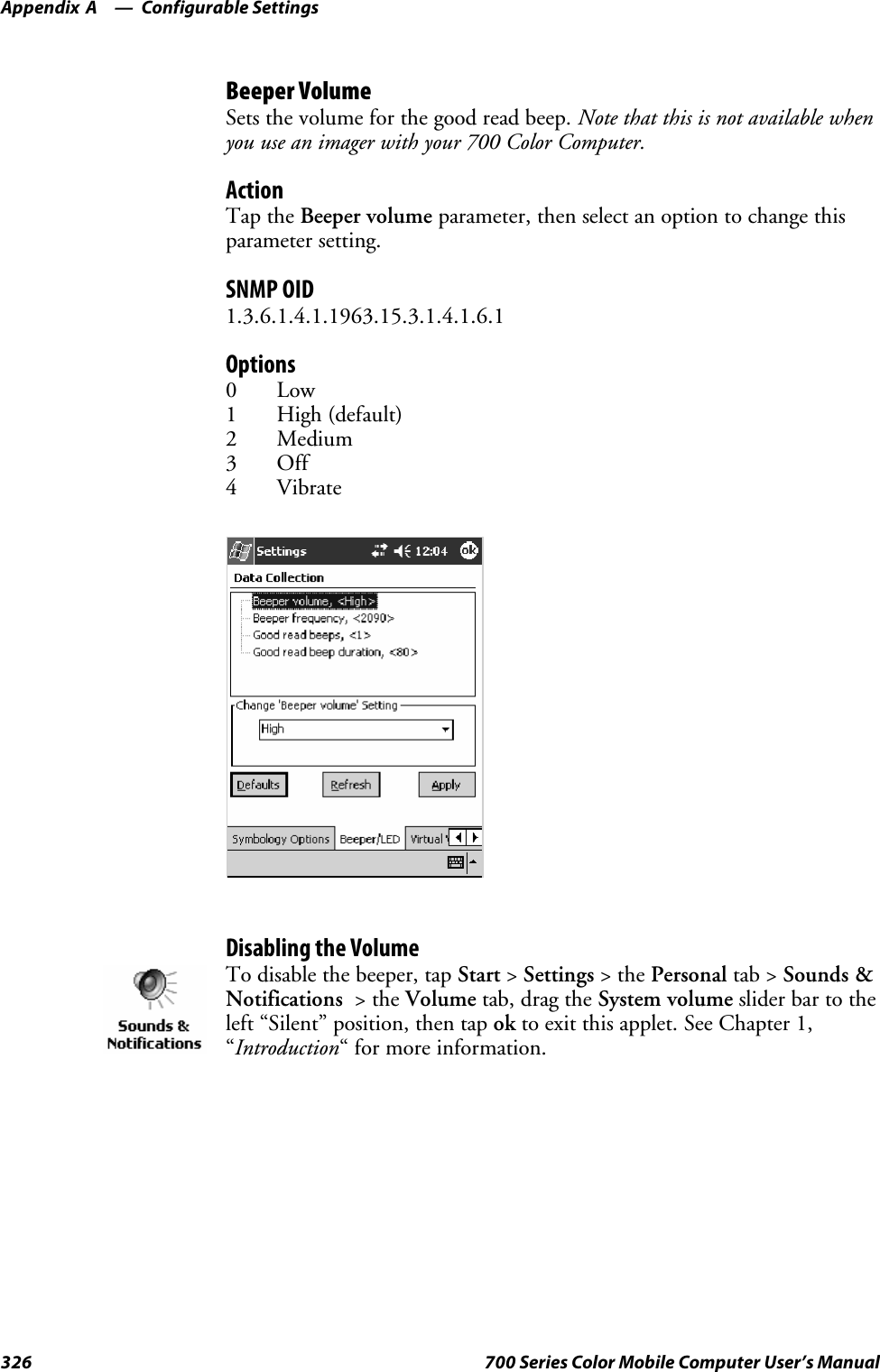
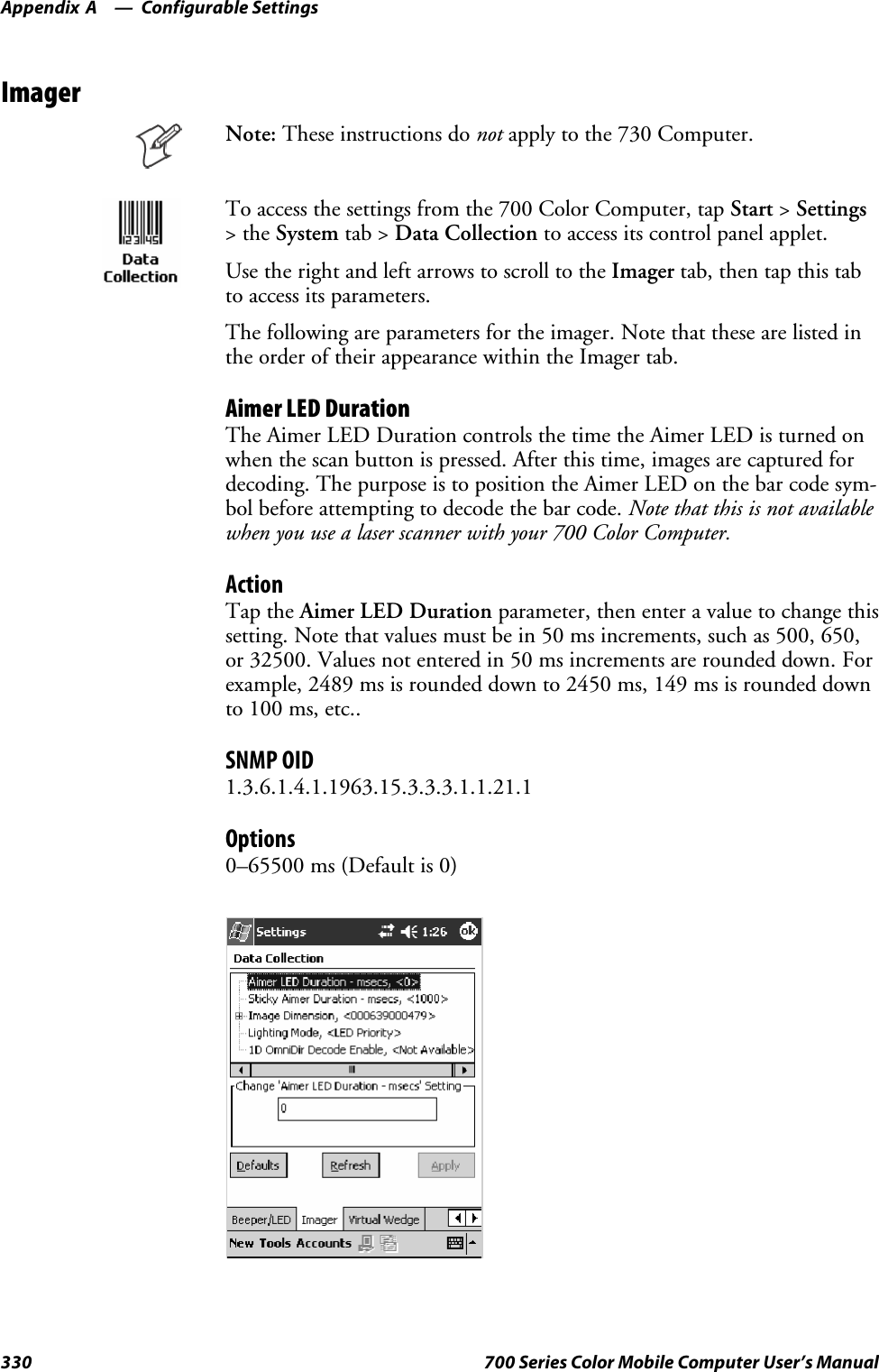
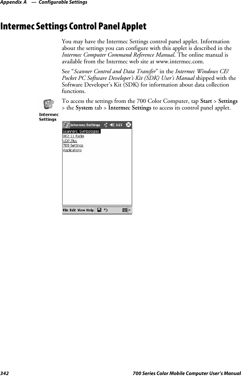
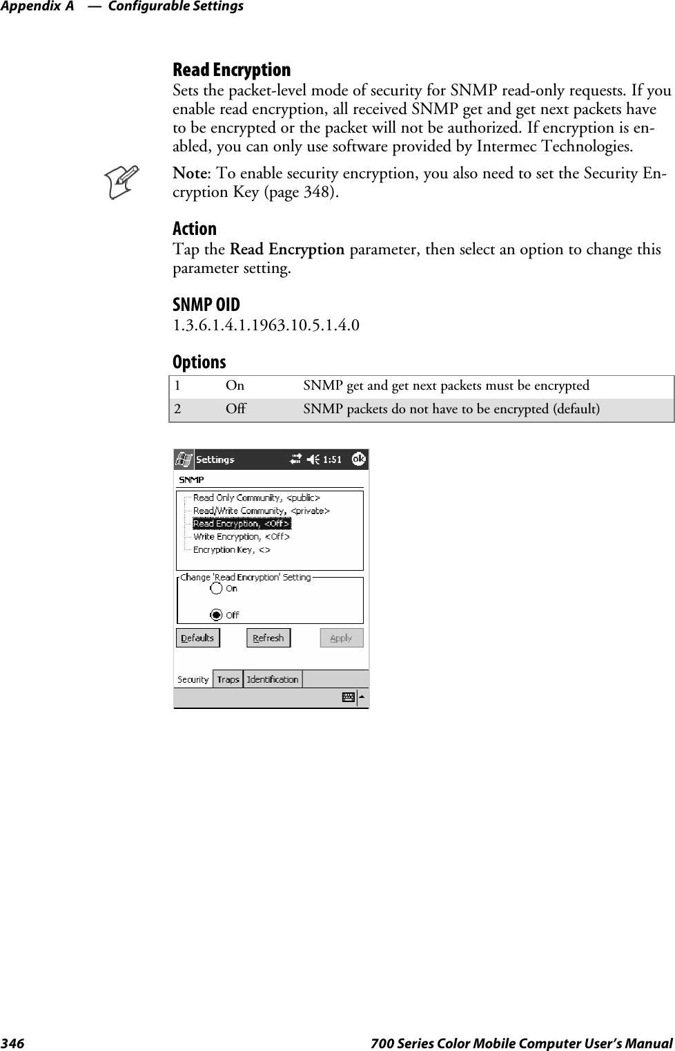
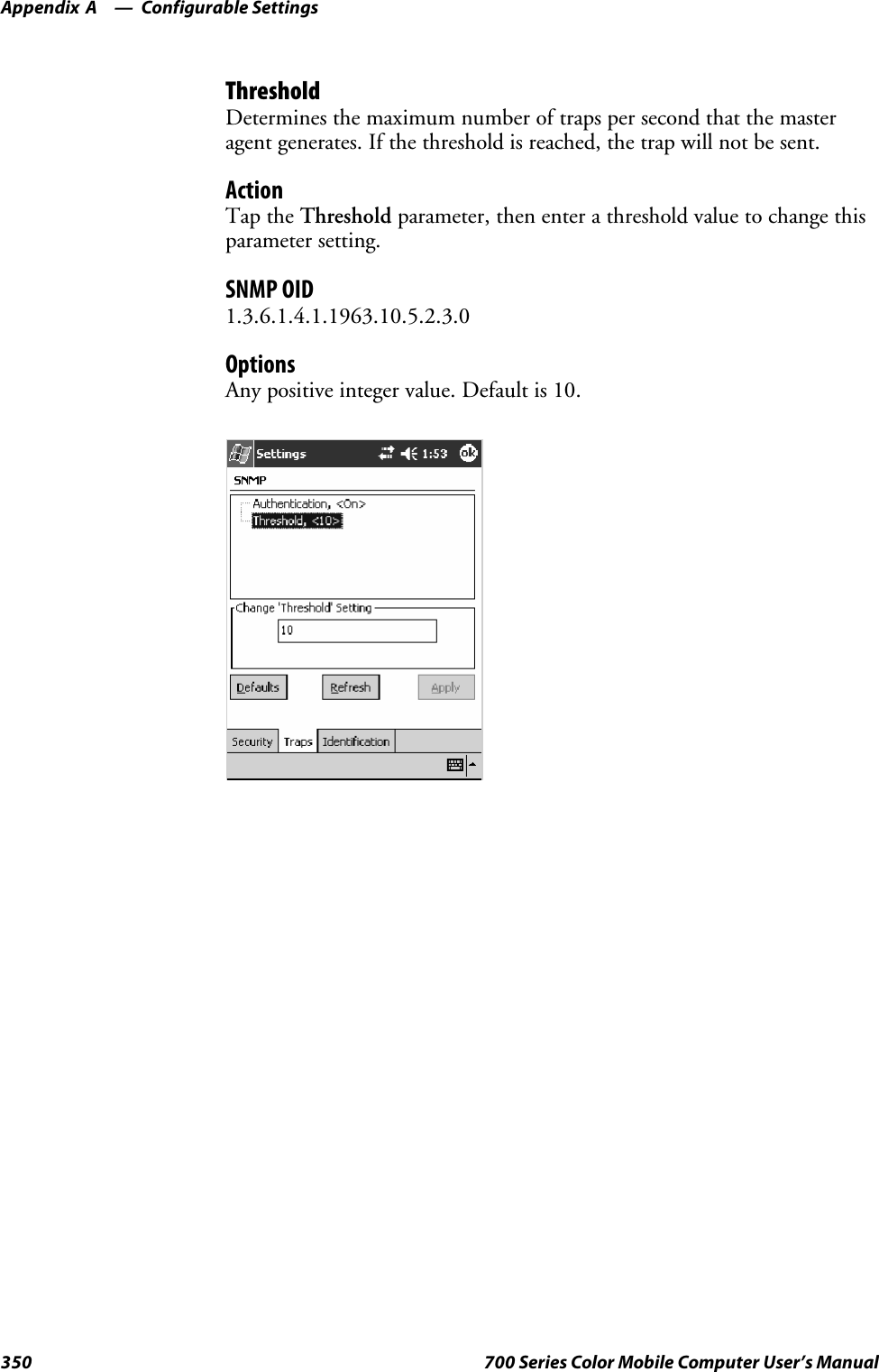
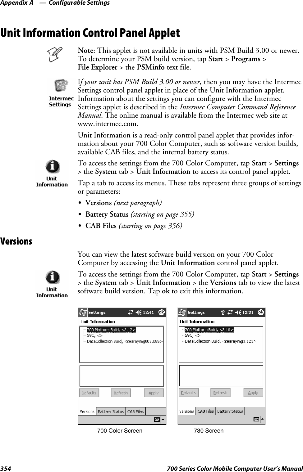
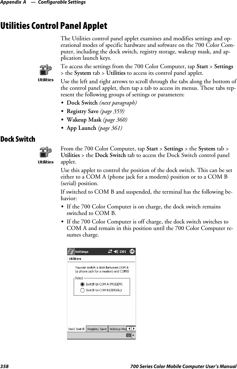
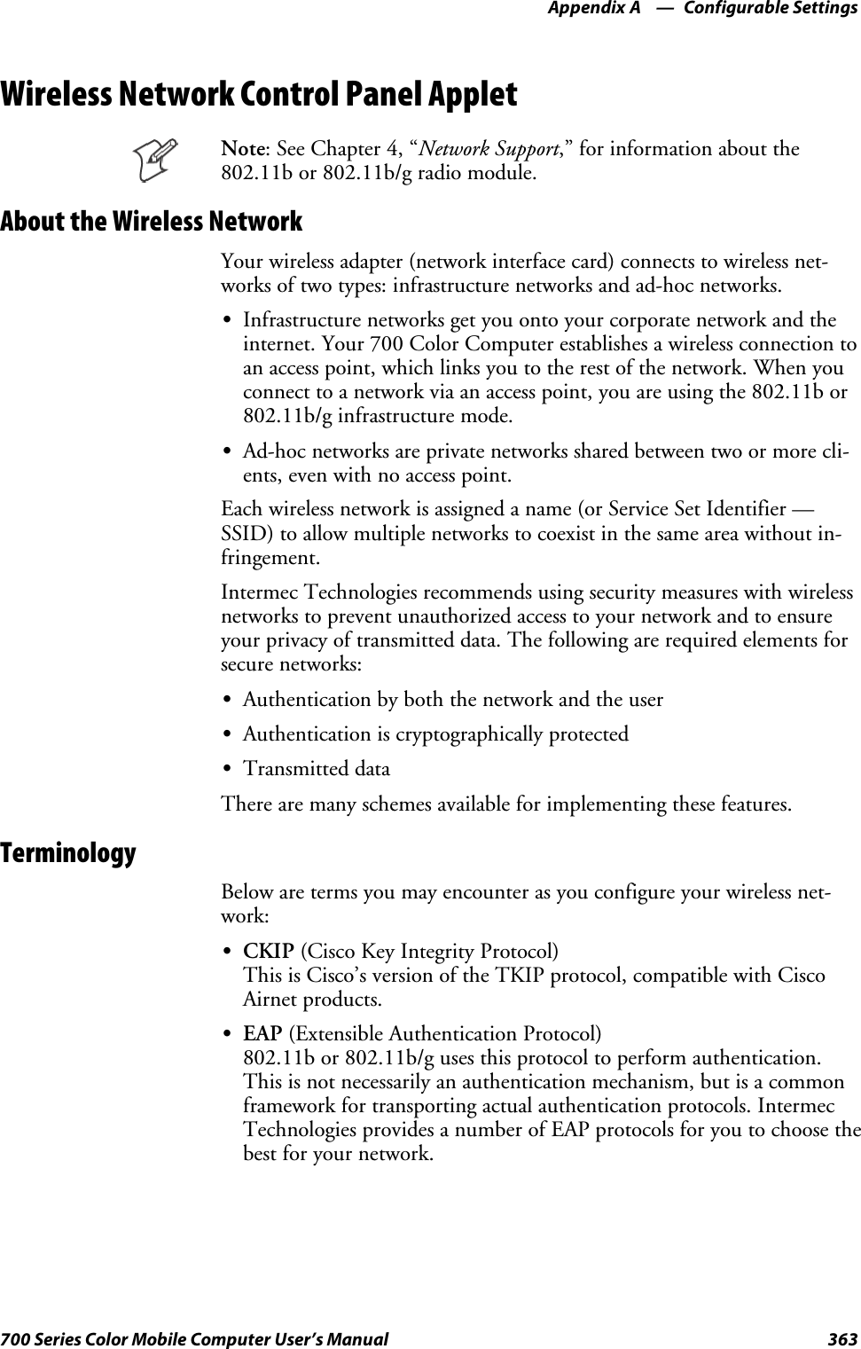
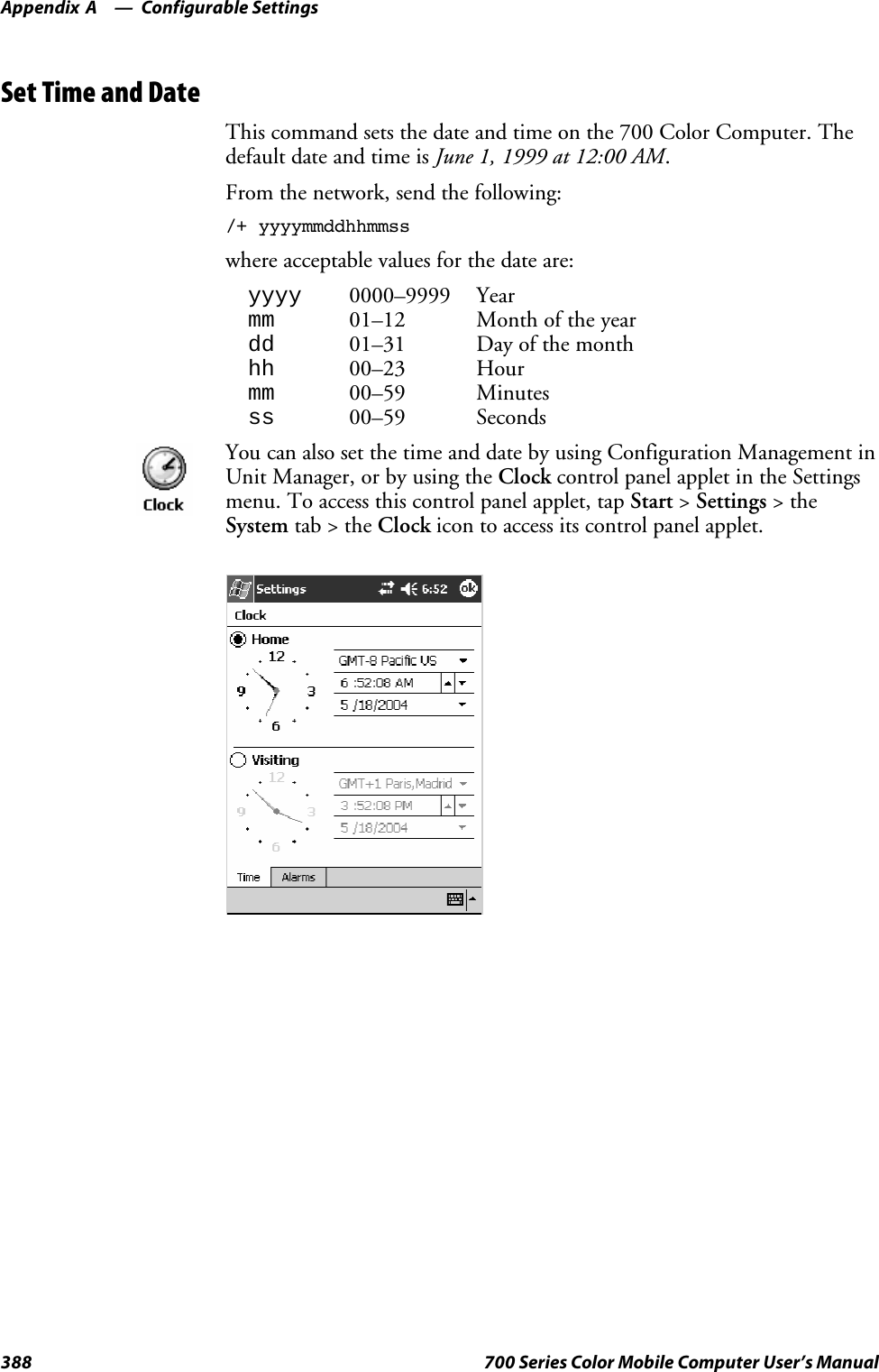
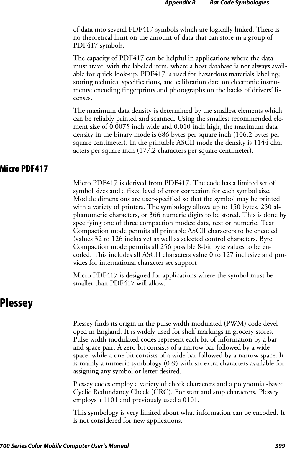
![Introduction—Chapter 113700 Series Color Mobile Computer User’s ManualAlphanumeric KeypadNote: This information does not apply to the 730 Computer.The following table lists sequences that use the [Gold/White] cplanekey. See Chapter 2, “Windows Mobile 2003,” for information about thePocket PC applications.Press the Keys To Do This[Gold/White]cIToggle the backlight on or off (also goes through backlightpower levels if held down)[Gold/White]cAAccess the Pocket PC Record application (see Note).[Gold/White]cBAccess the Pocket PC Calendar application (see Note).[Gold/White]cCAccess the Pocket PC Contacts application (see Note).[Gold/White]cDAccess the Pocket PC Tasks application (see Note).[Gold/White]cJMove up one page.[Gold/White]cGEnter an asterisk (*).[Gold/White]cPMove down one page.[Gold/White]cEAccess the Pocket PC Start menu.[Gold/White]cKEnter an at symbol (@).[Gold/White]cHEnter a backslash (/).[Gold/White]cLEnter a minus sign (–).[Gold/White]cREnter a plus sign (+).[Gold/White]clTab to the right.[Gold/White]cjTab to the left.[Gold/White]ckIncrease volume[Gold/White]cmDecrease volumeNote: Pocket PC applications are accessible only if configured to do so in the App Launchportion of the Utilities control panel applet. See page 358 for more information.](https://usermanual.wiki/Intermec-Technologies/2610CF.700C-User-Manual-1-of-3/User-Guide-527885-Page-35.png)
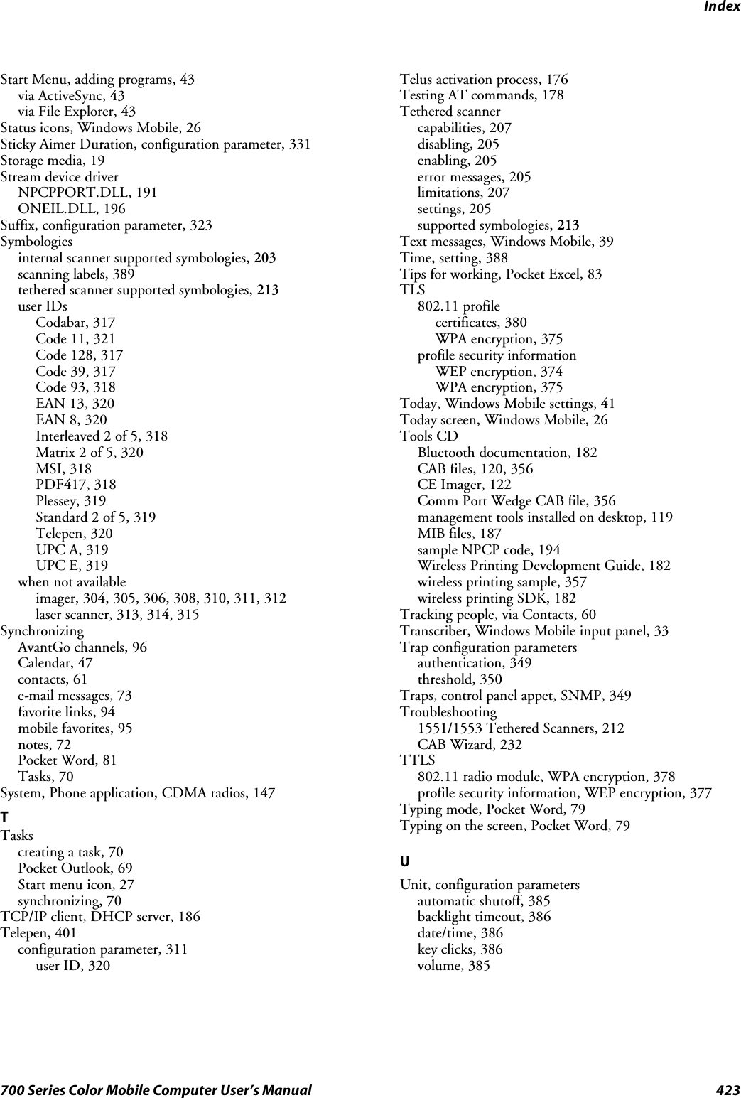
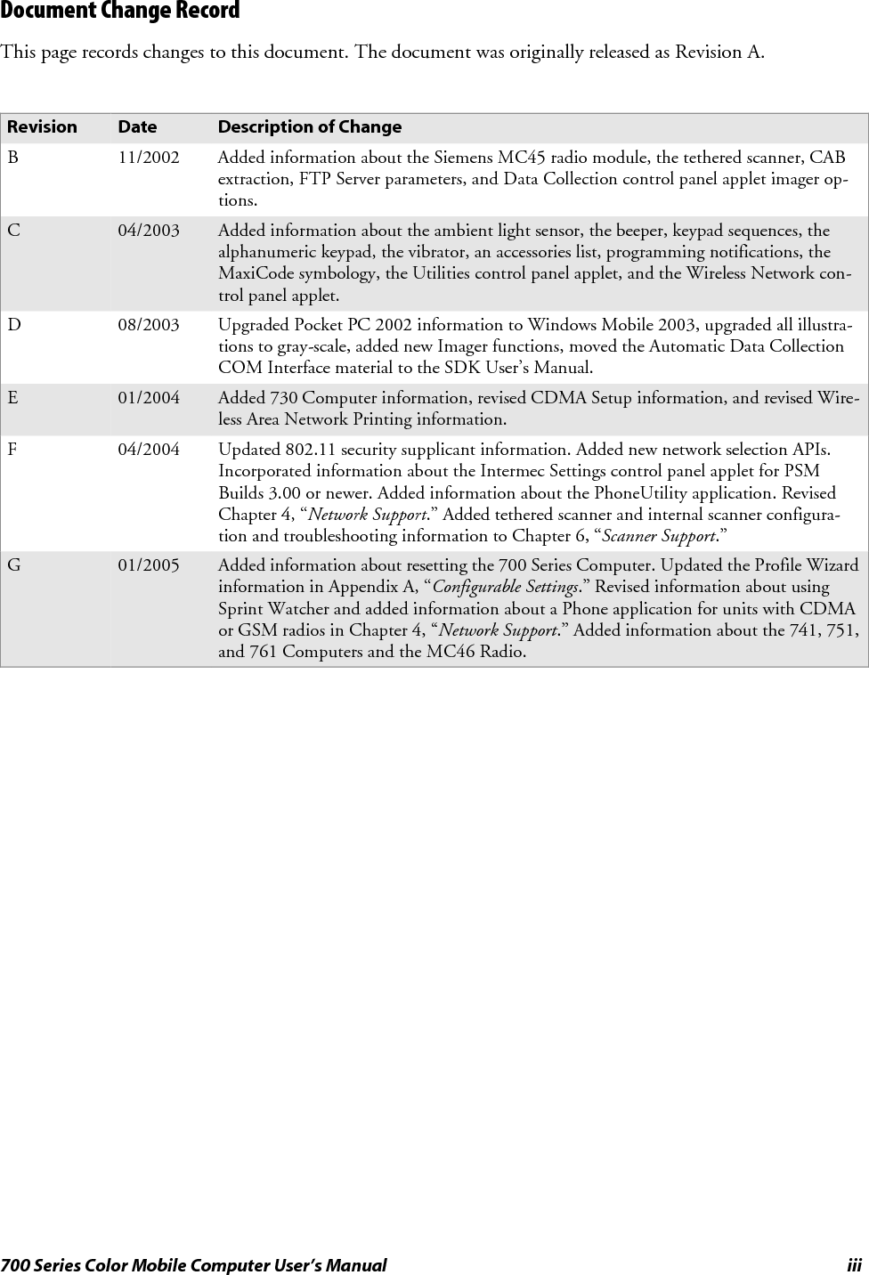
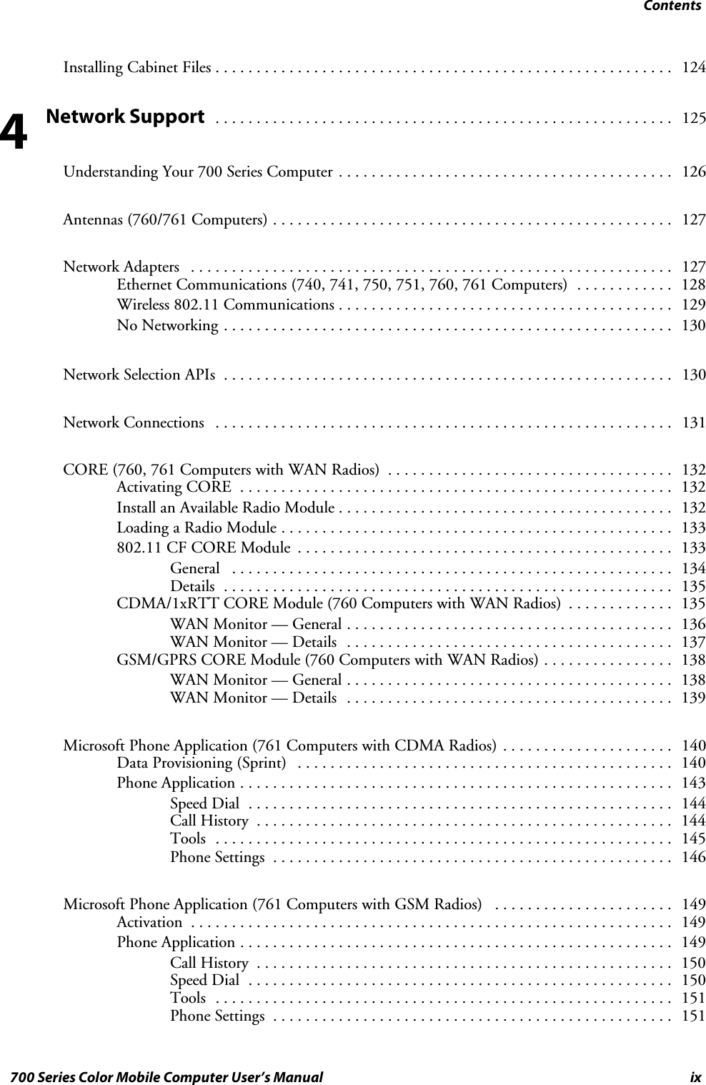
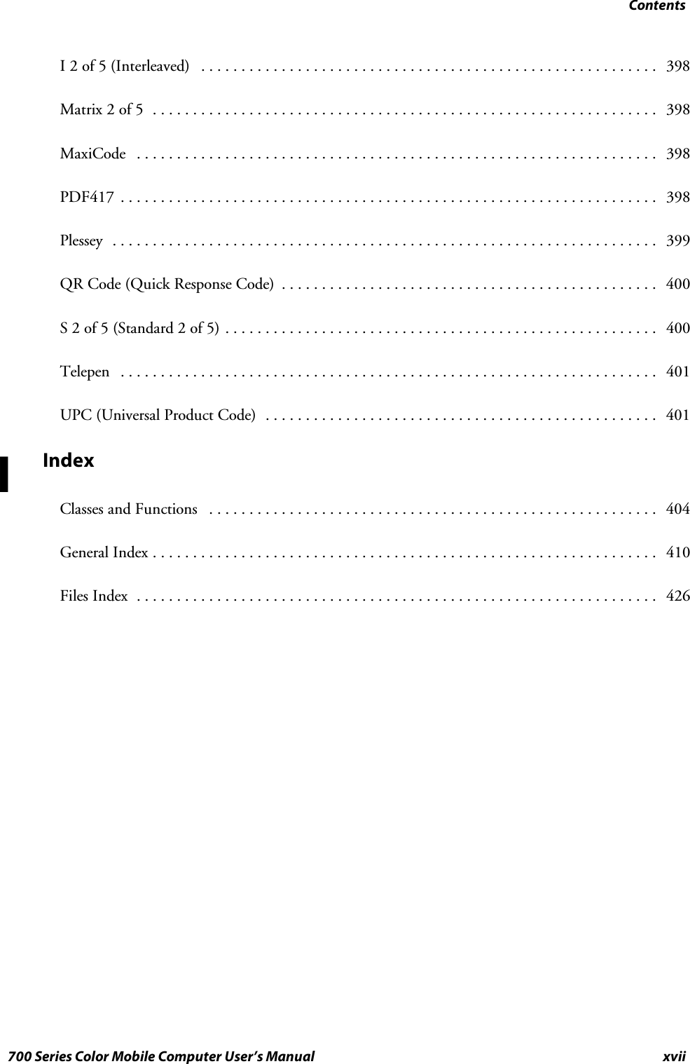
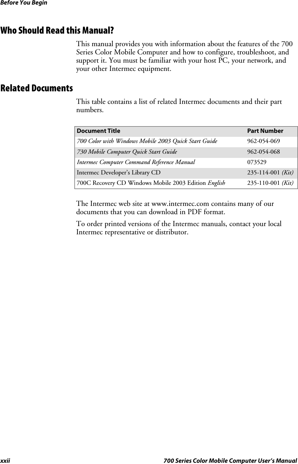
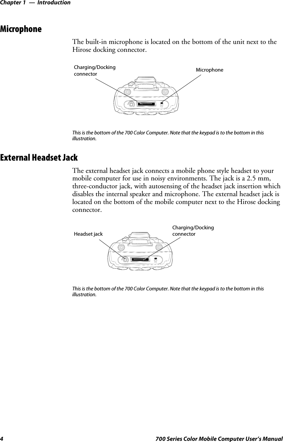
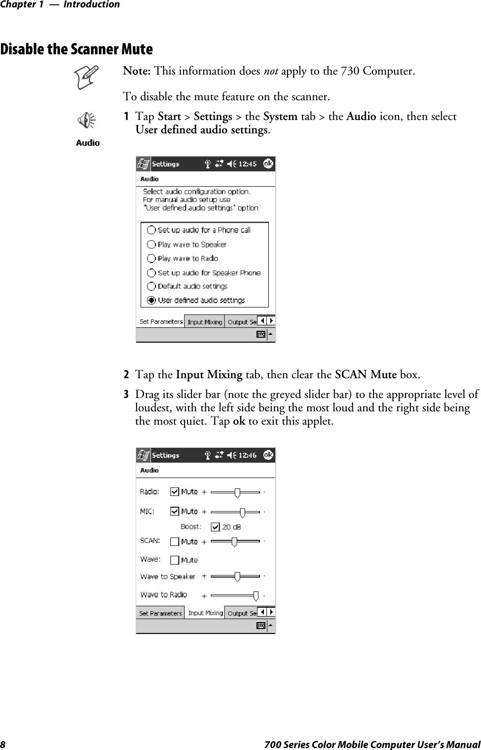
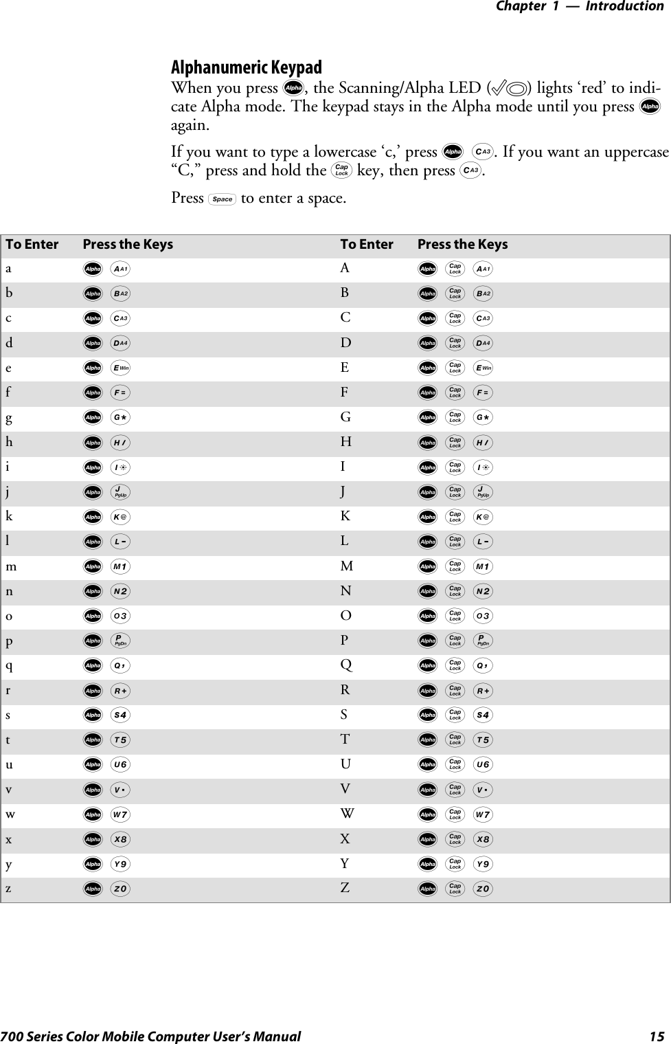
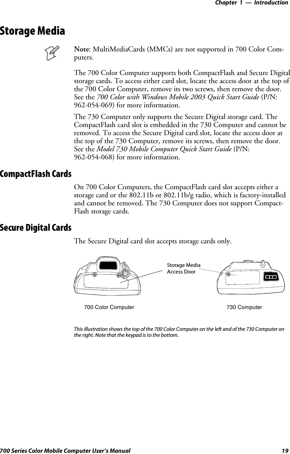
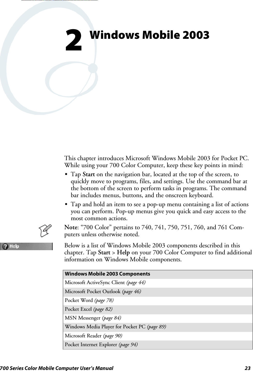
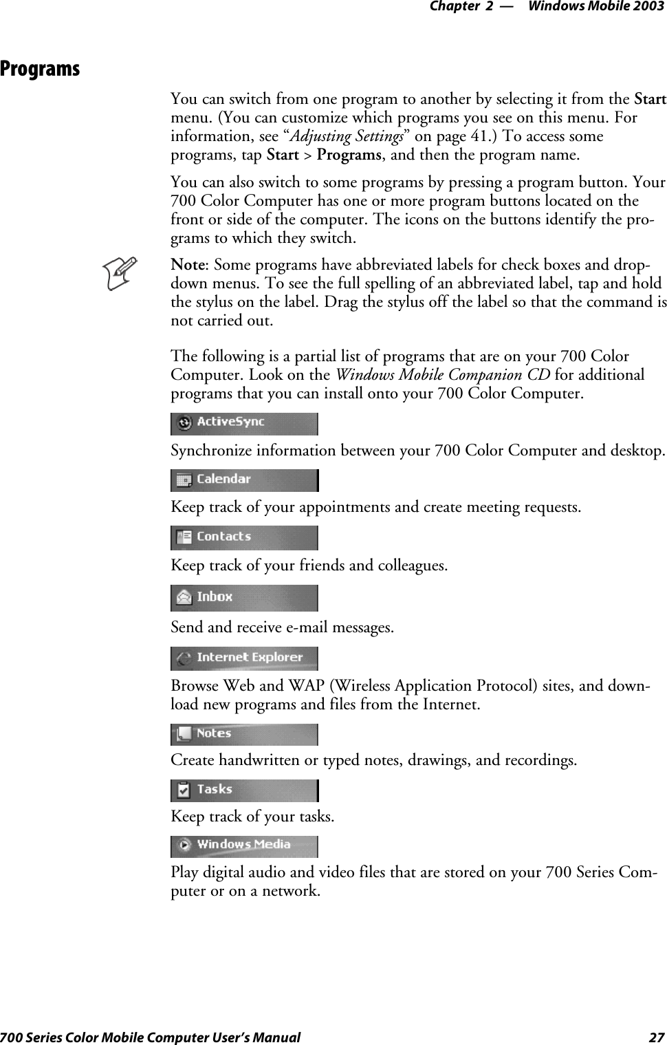
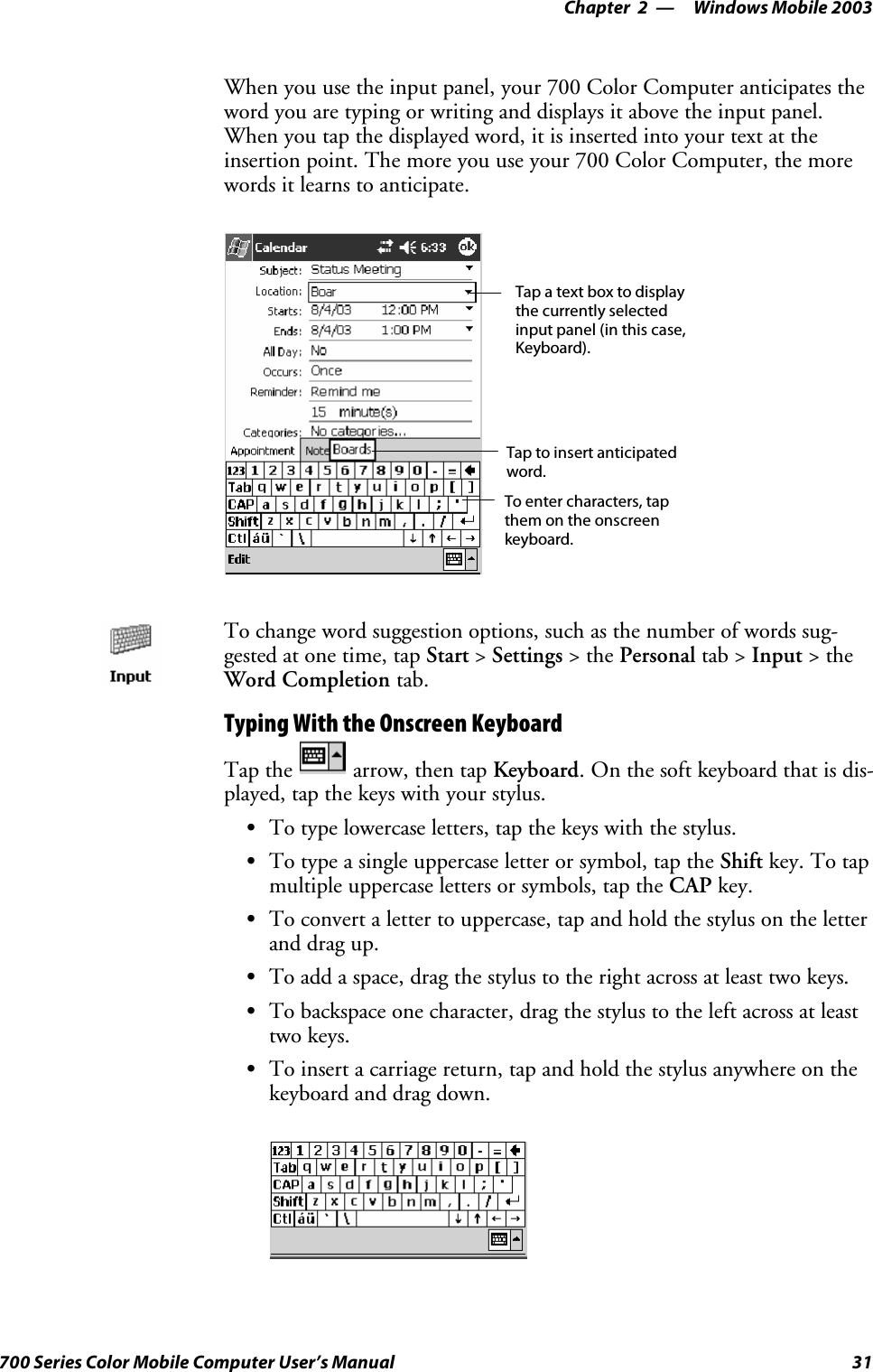
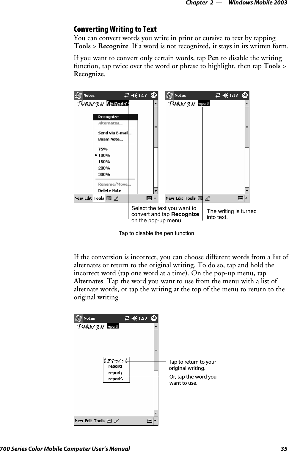
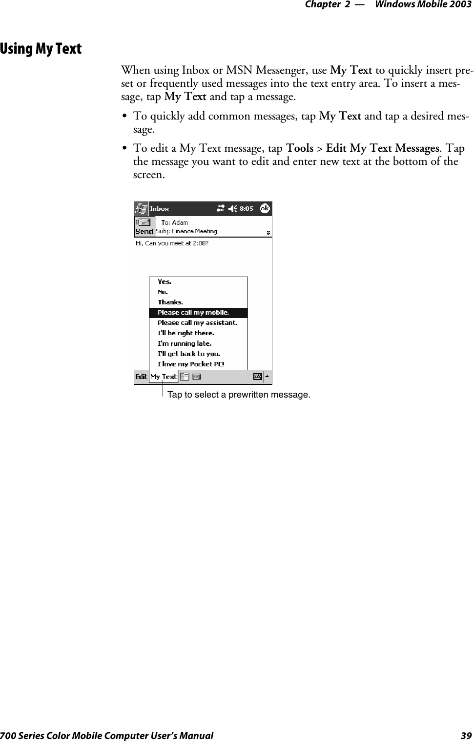
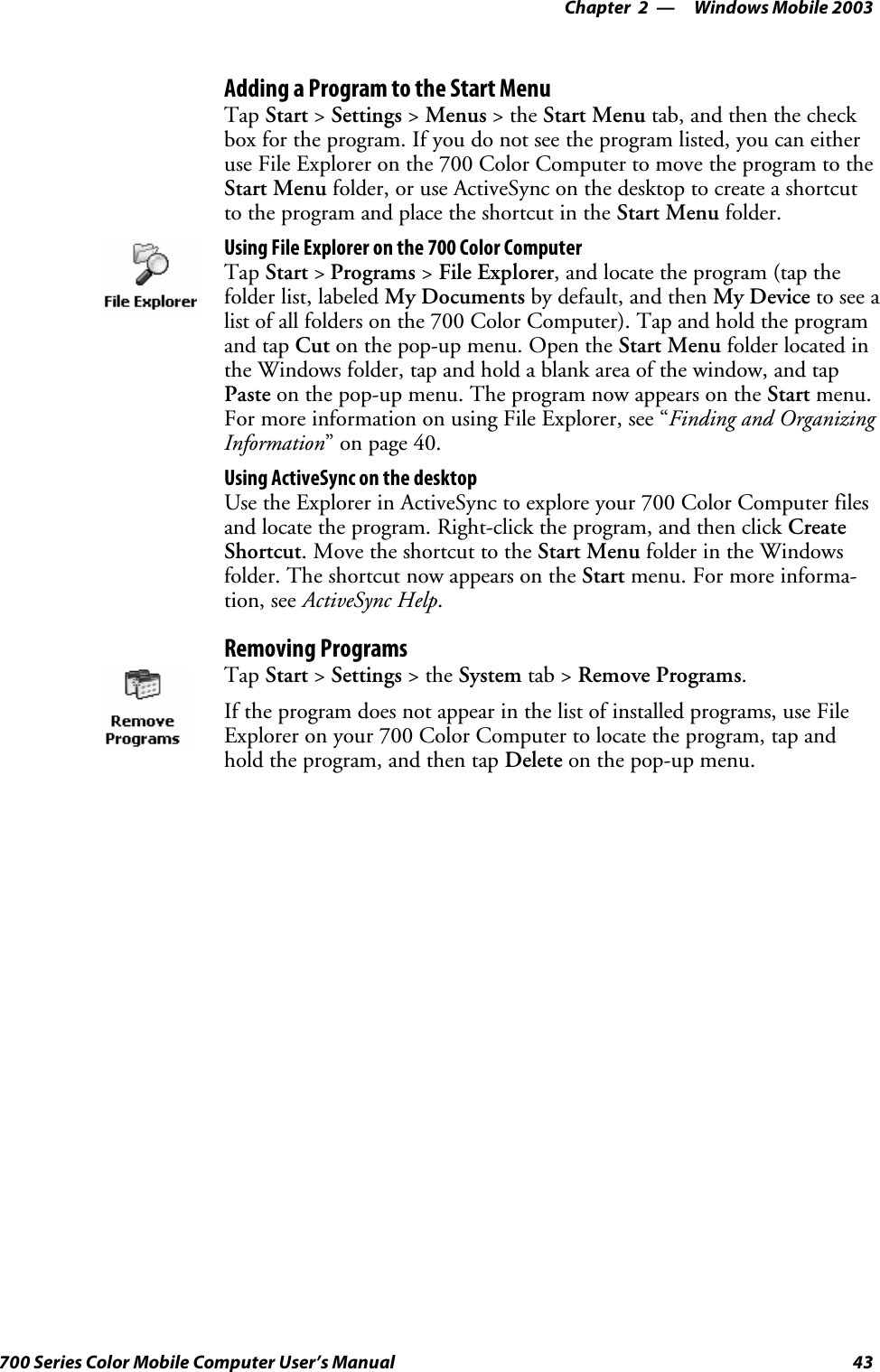
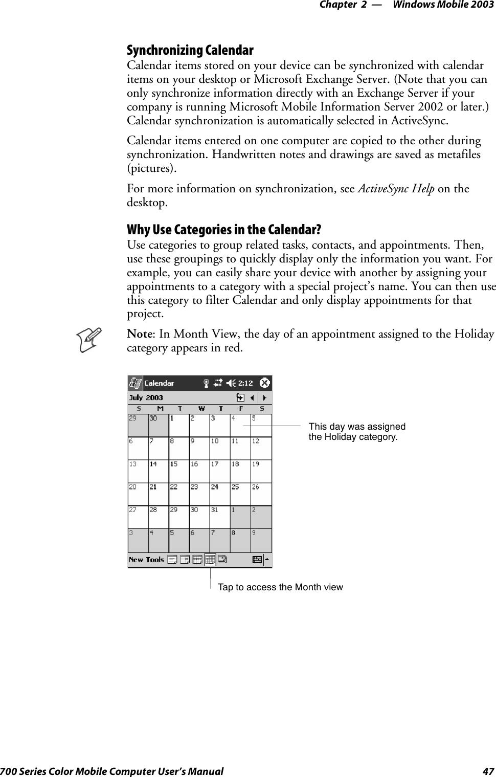
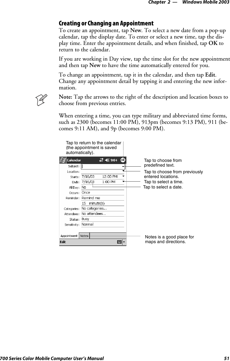
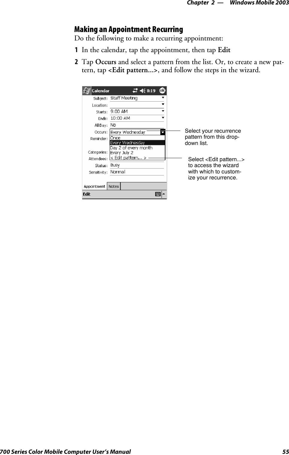
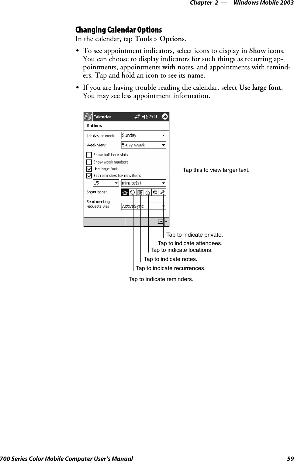
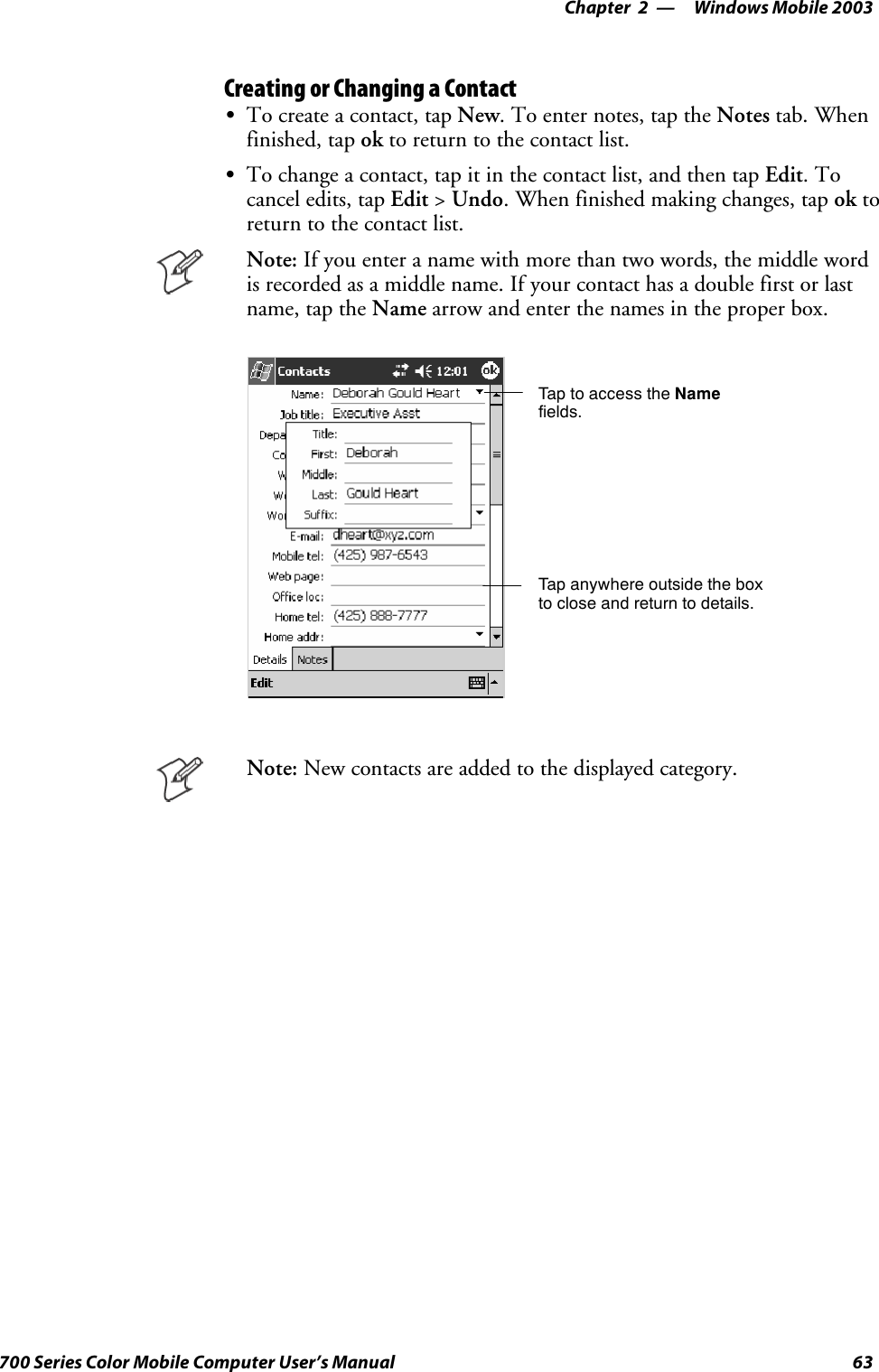
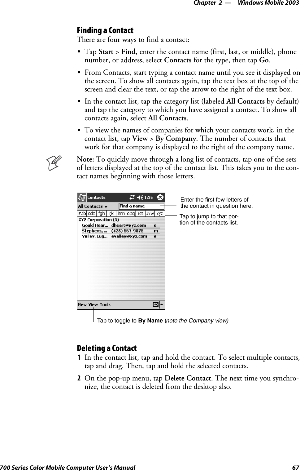
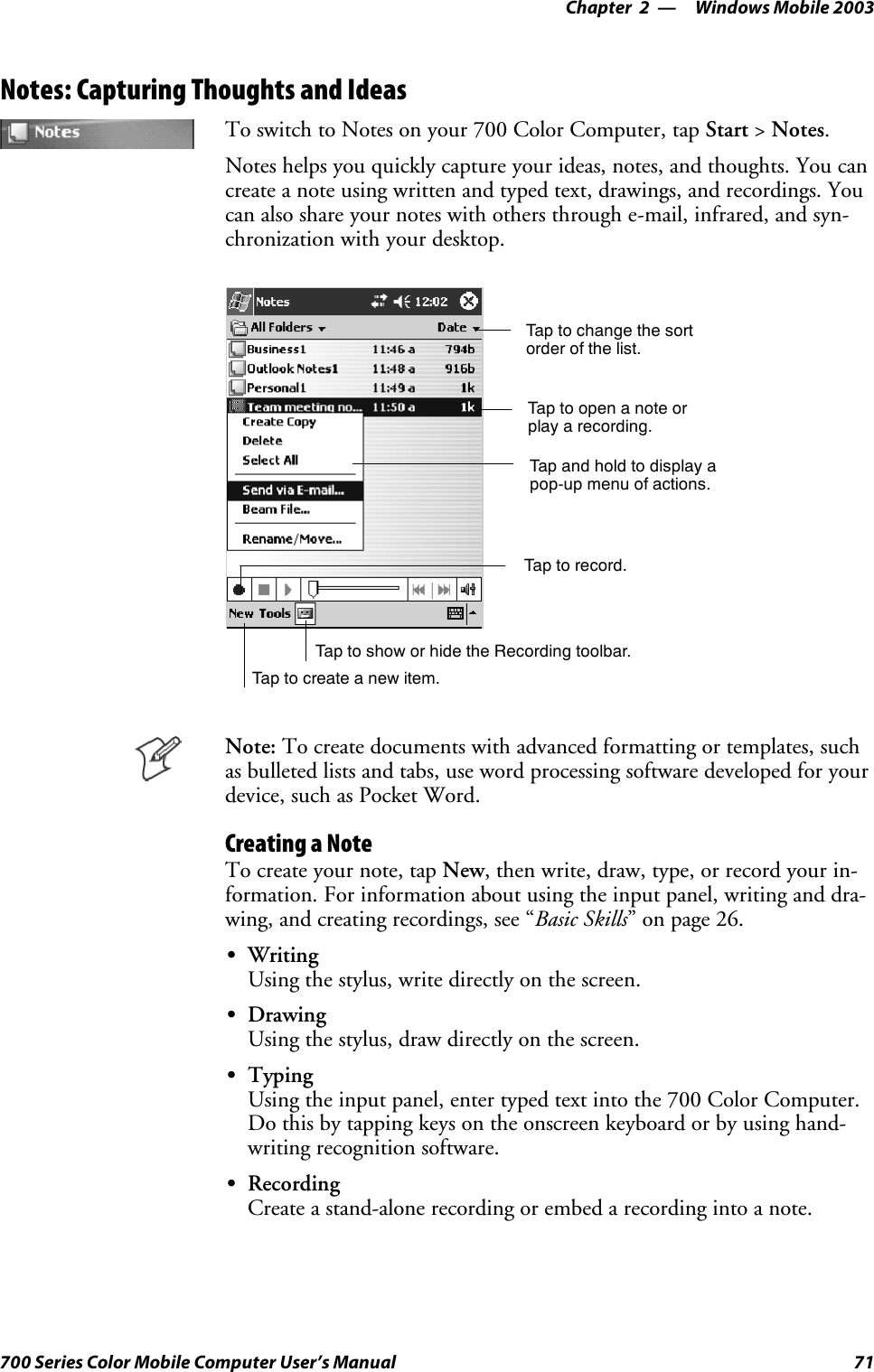
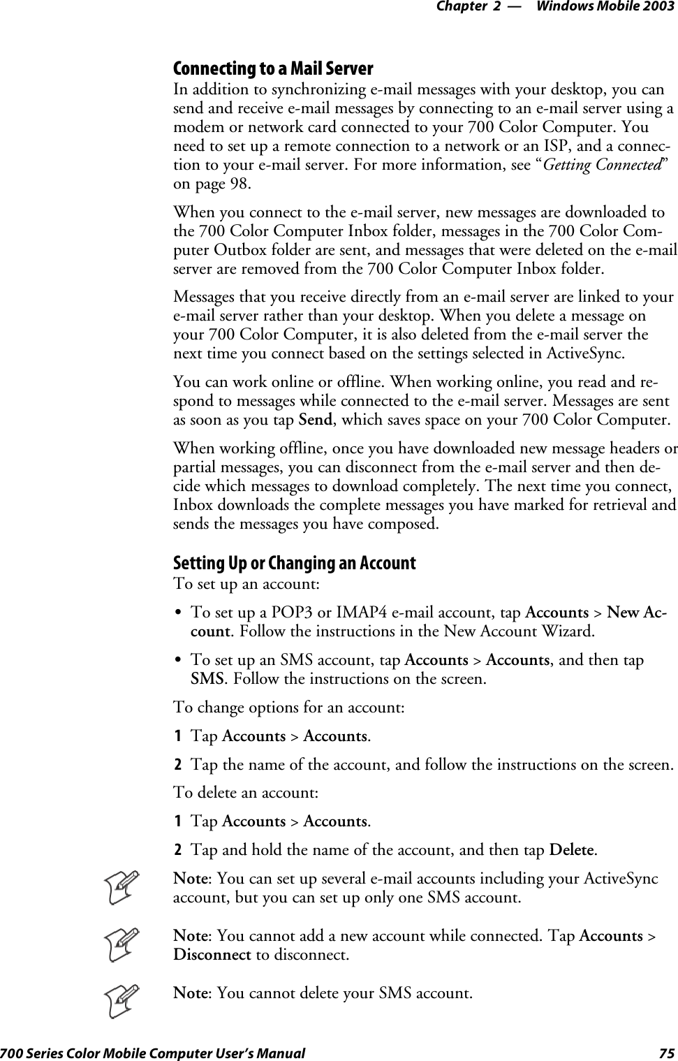
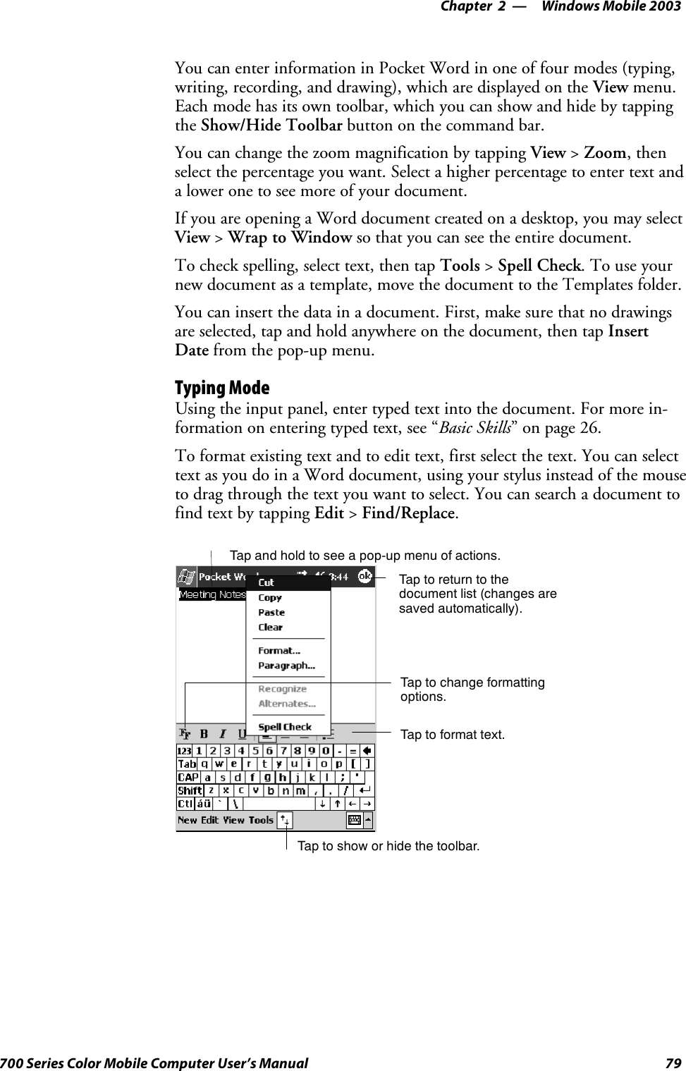
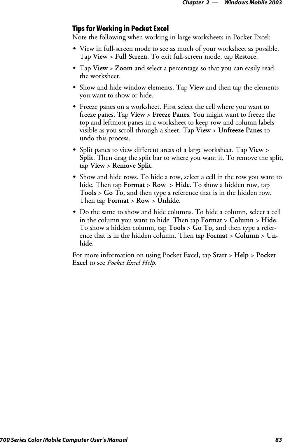
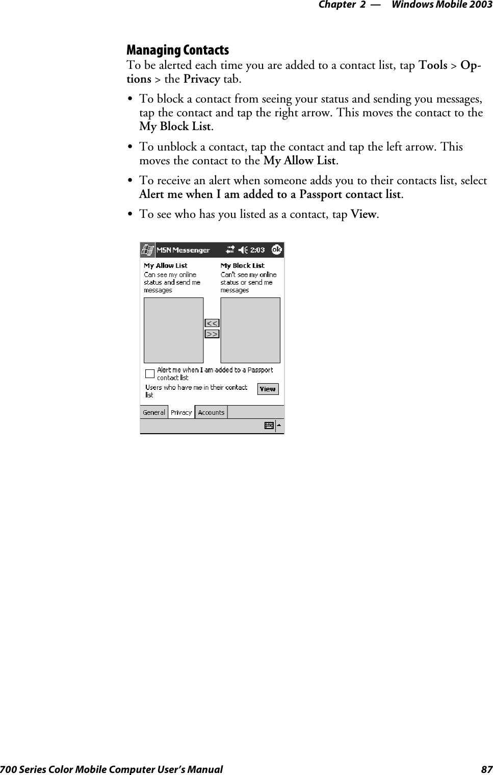
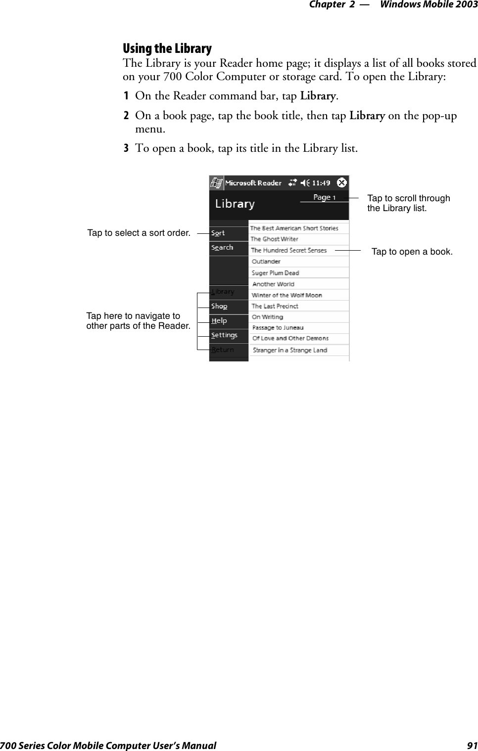
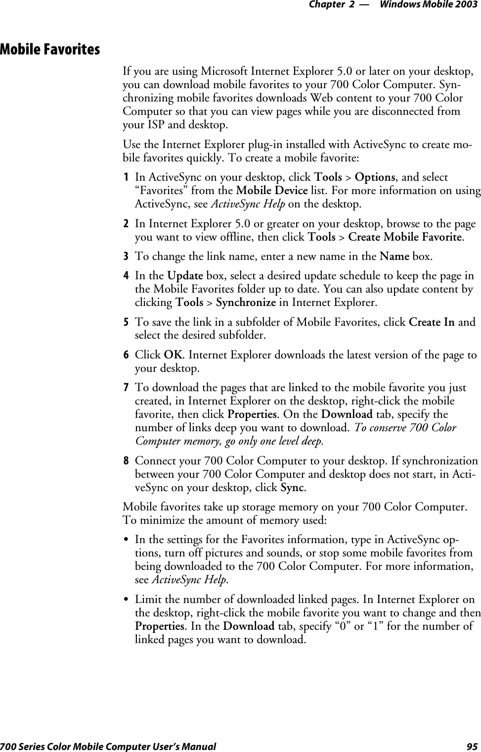
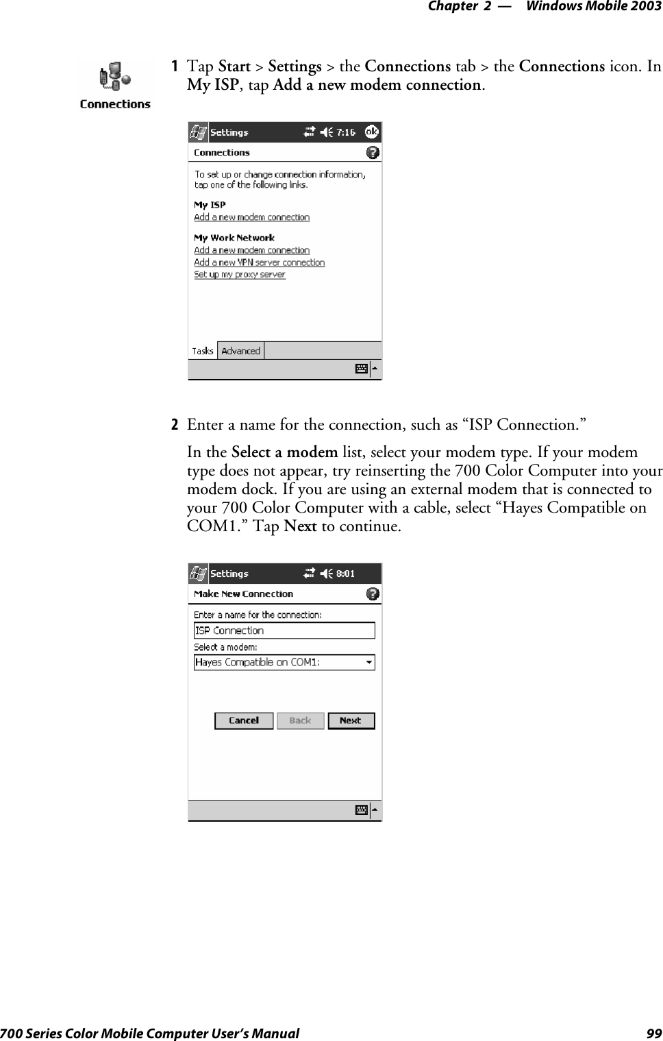
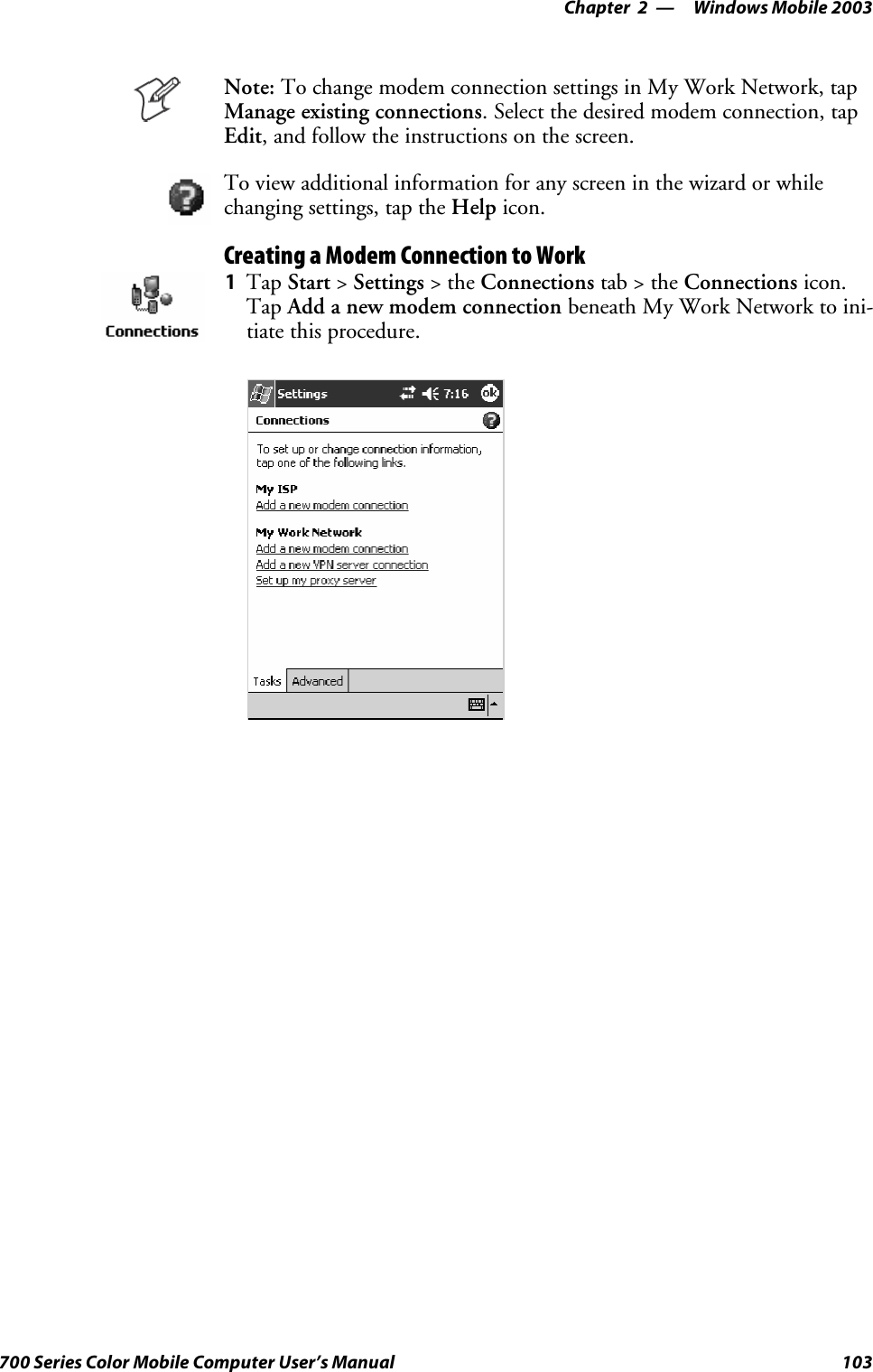
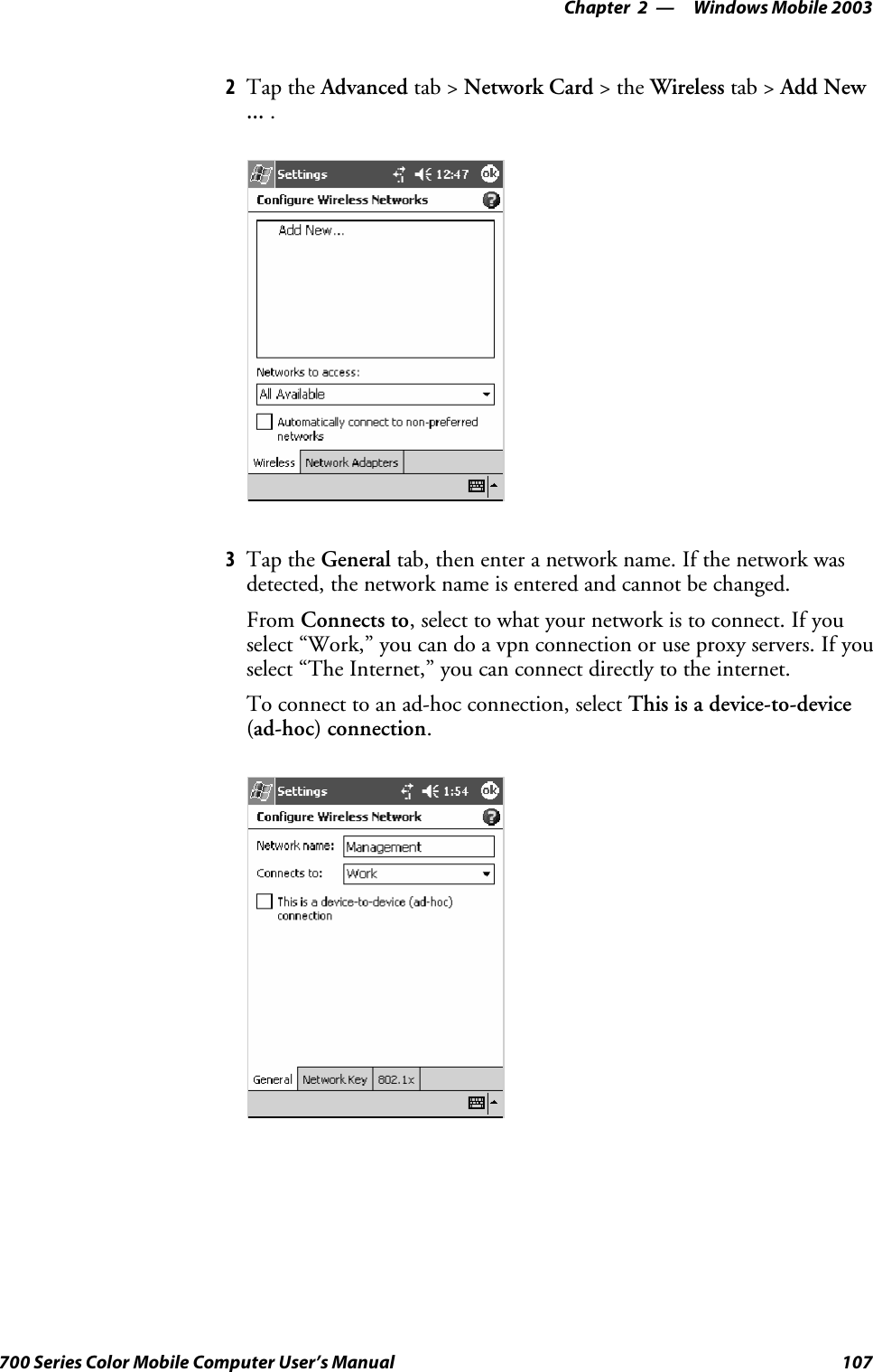
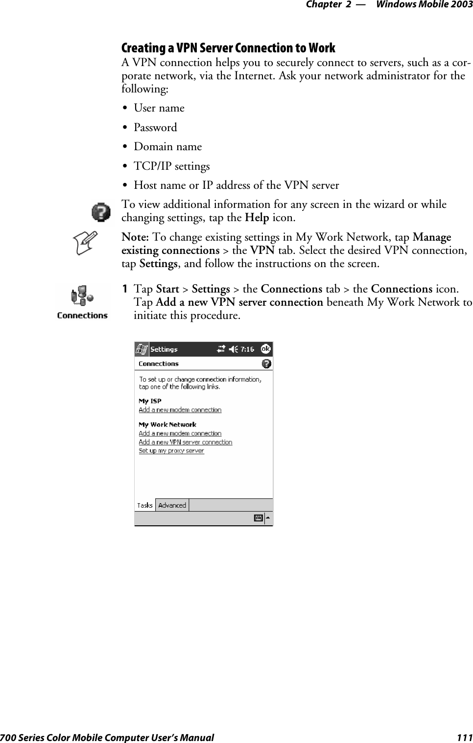
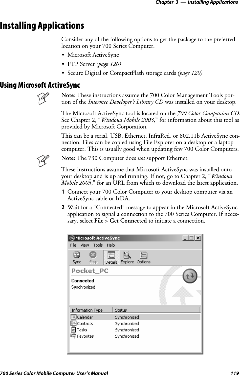
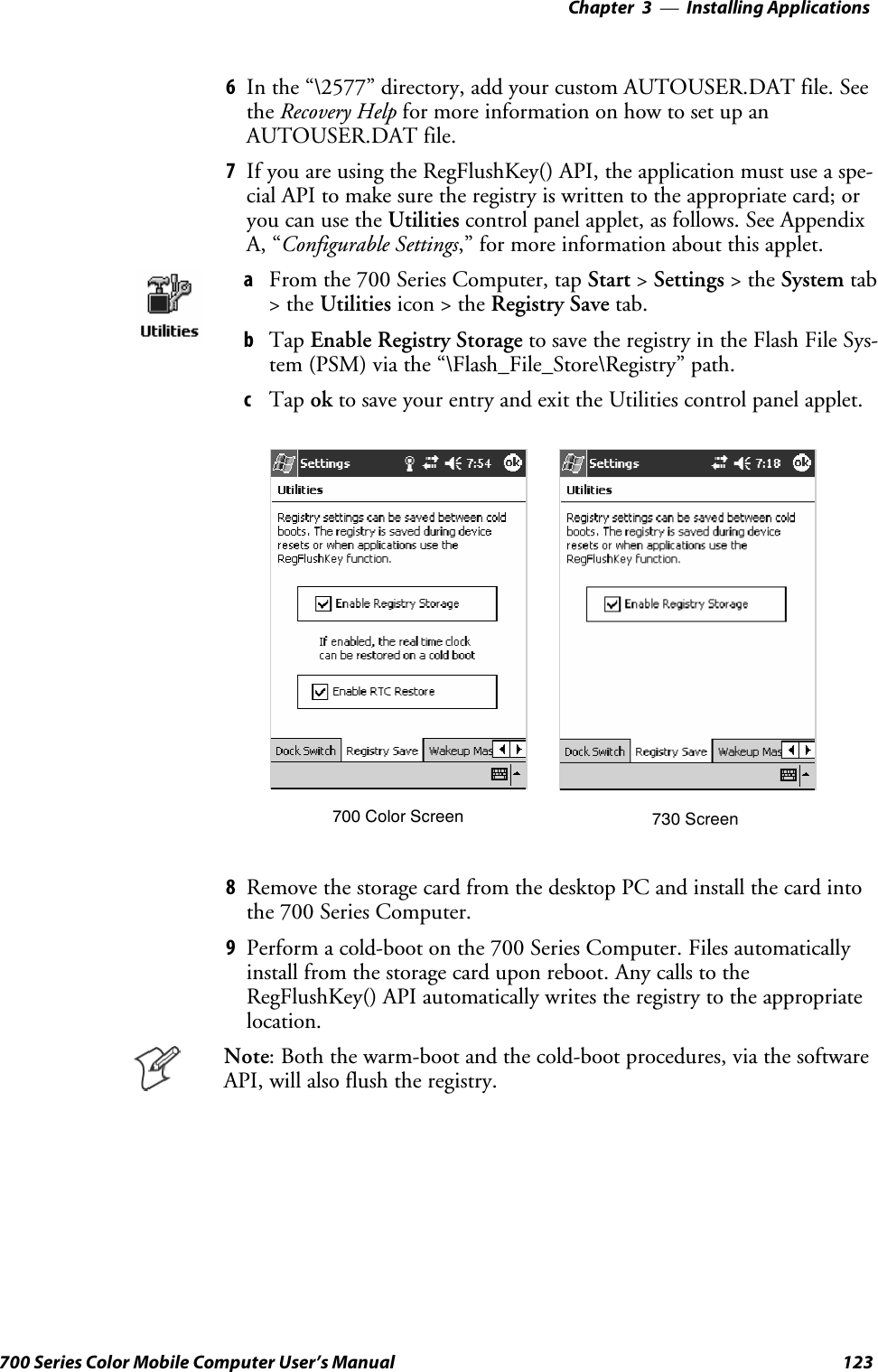
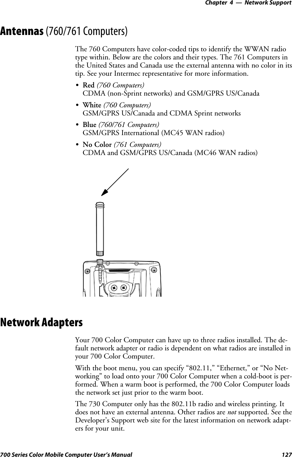
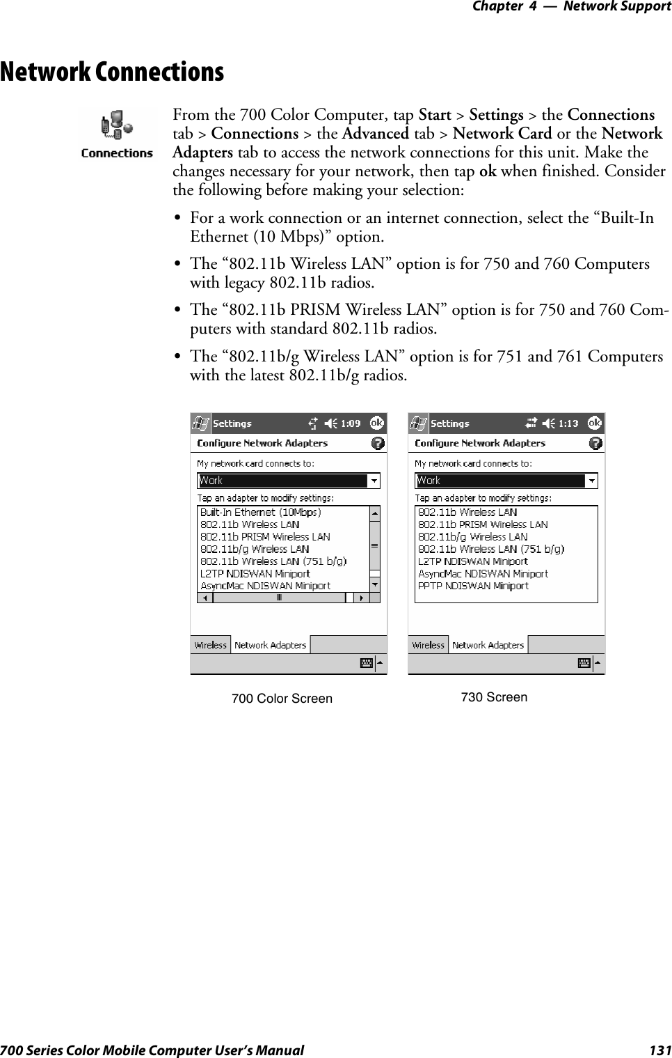
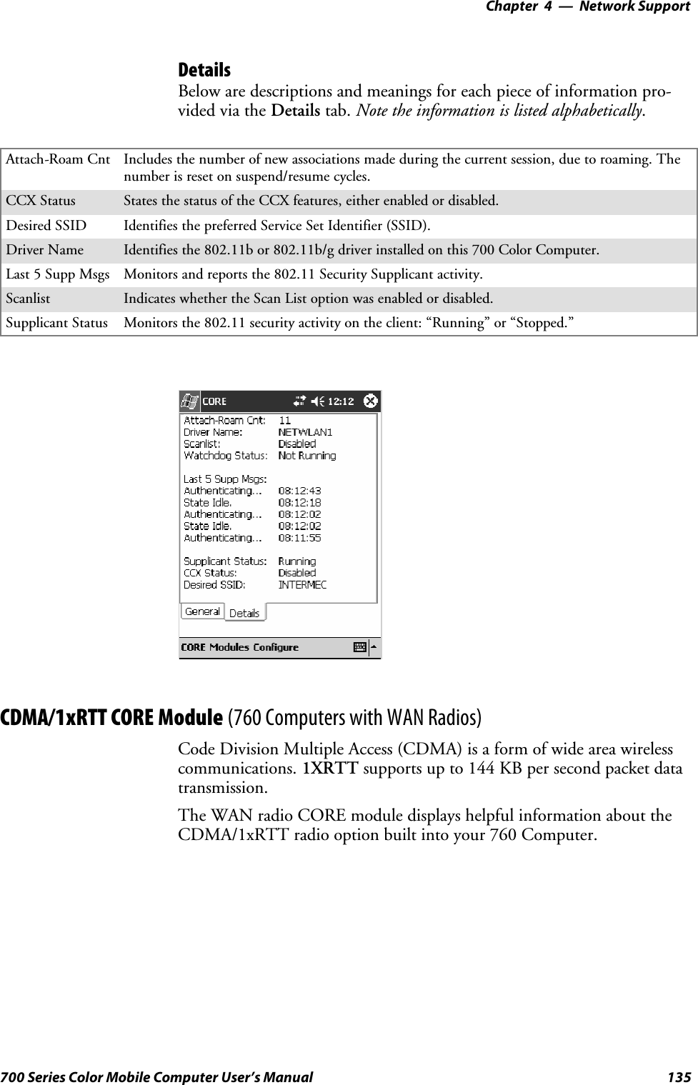
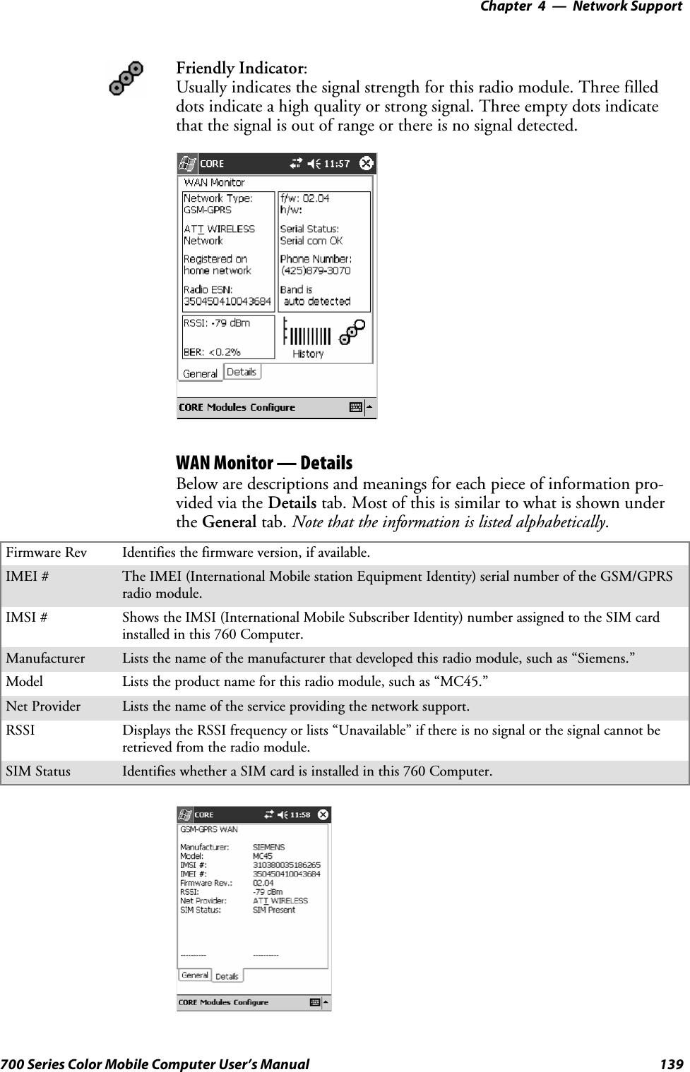
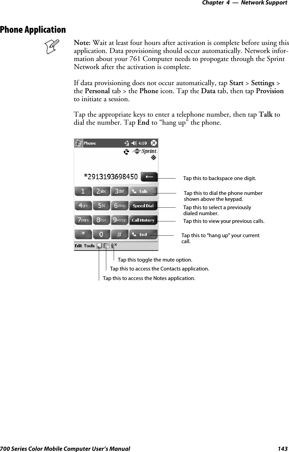
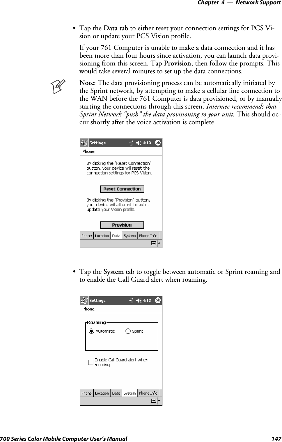
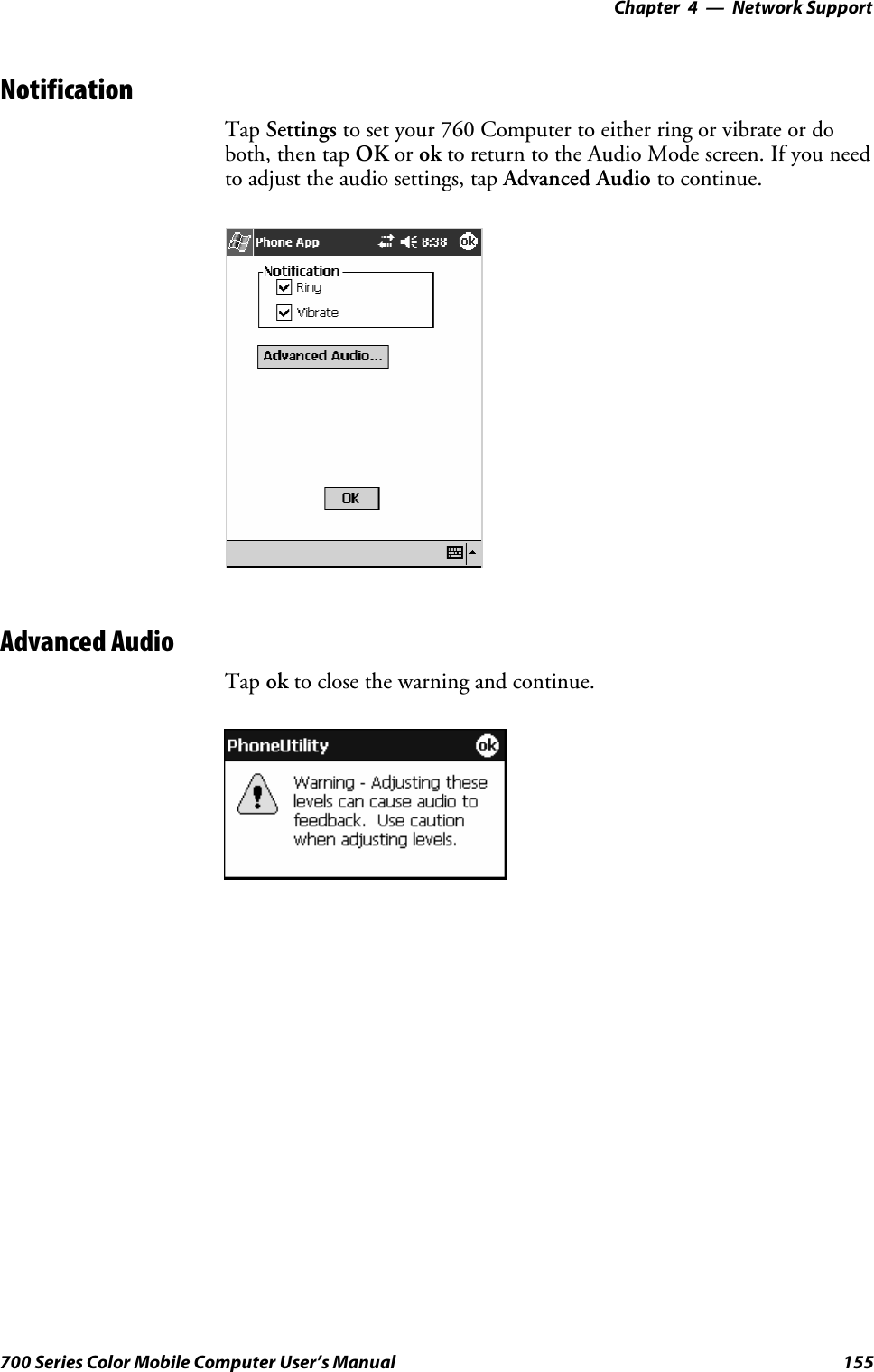
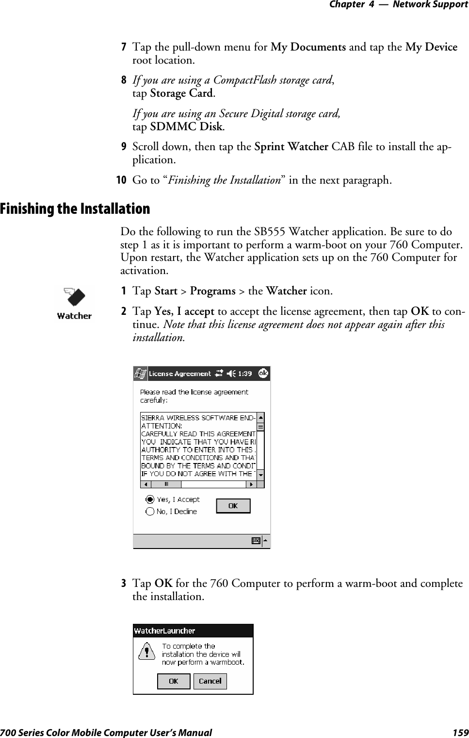
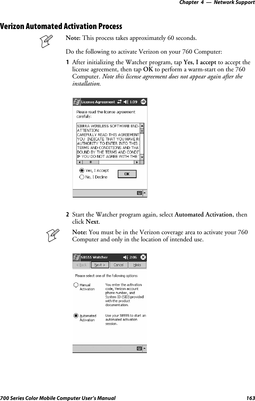
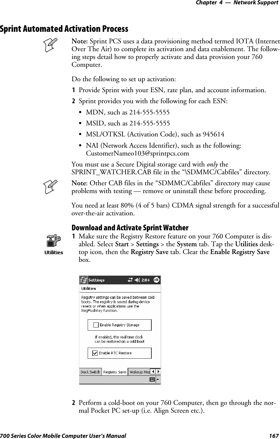
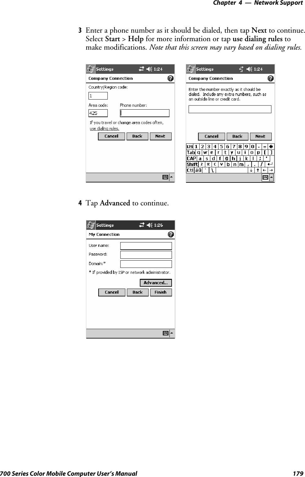
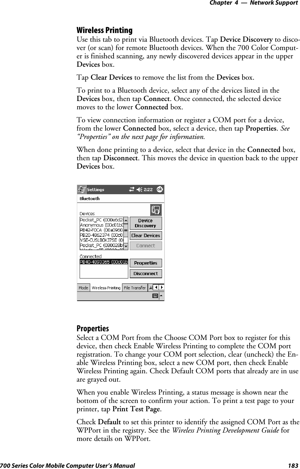
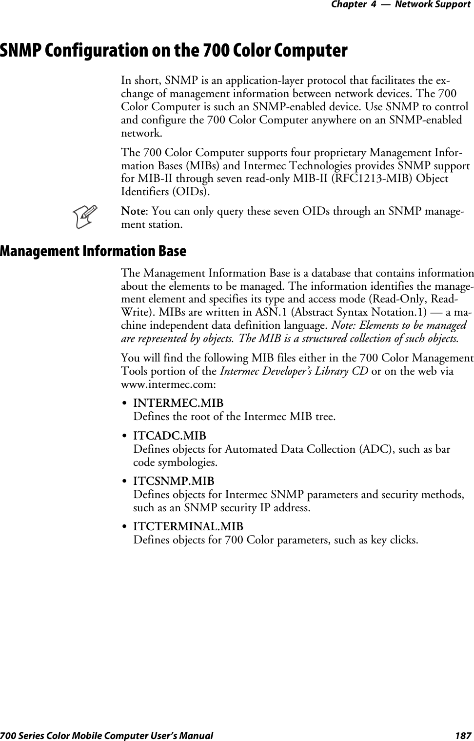
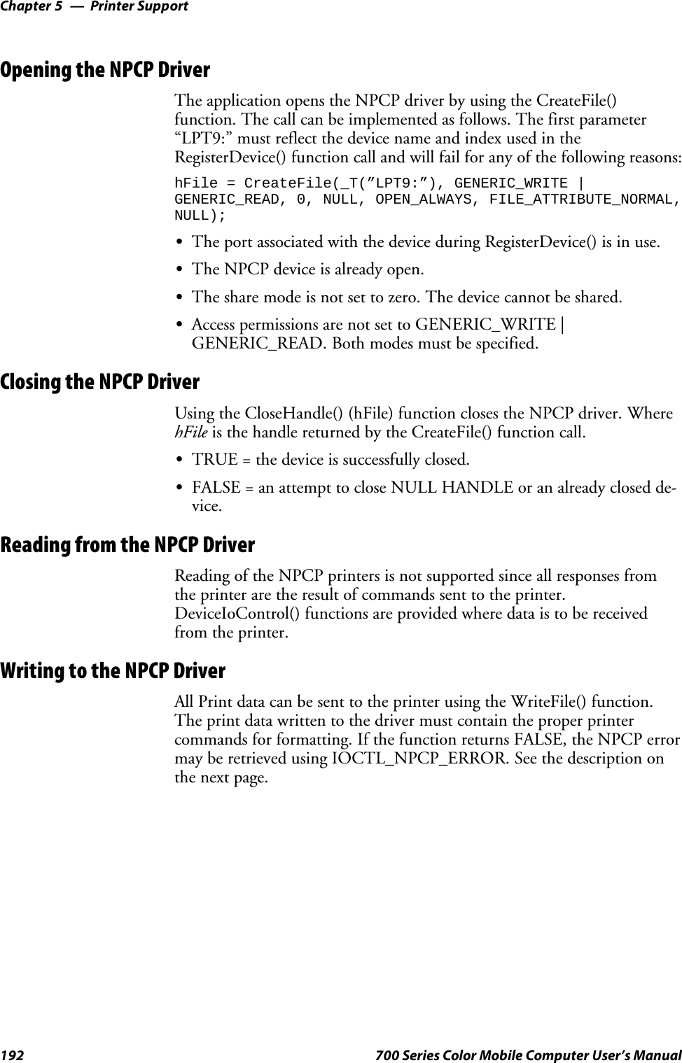
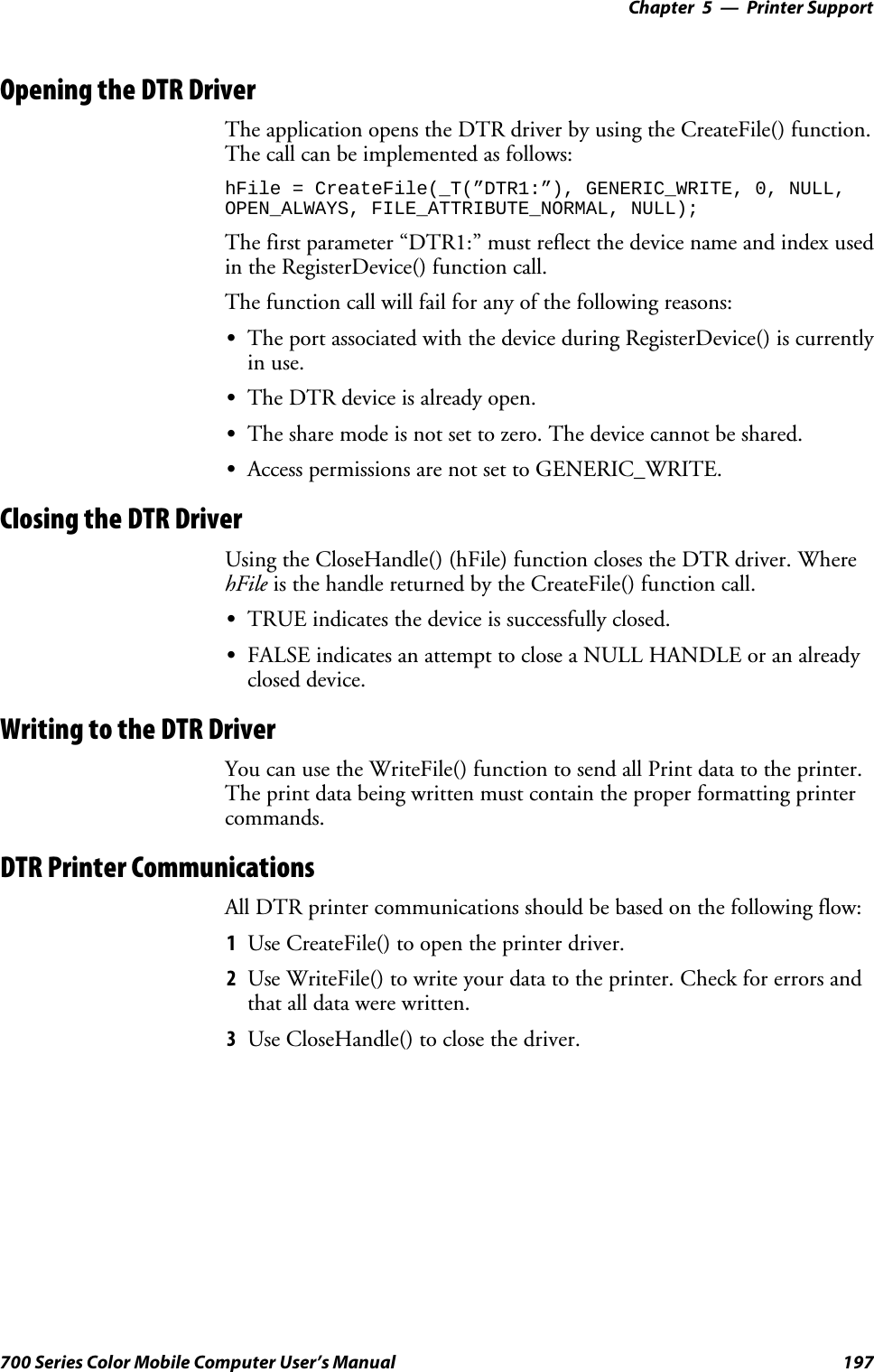
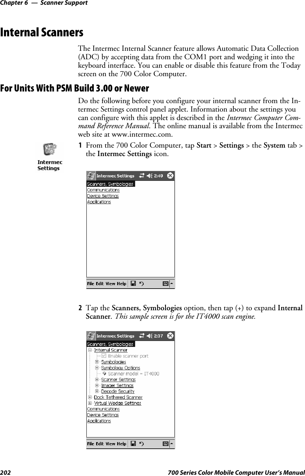
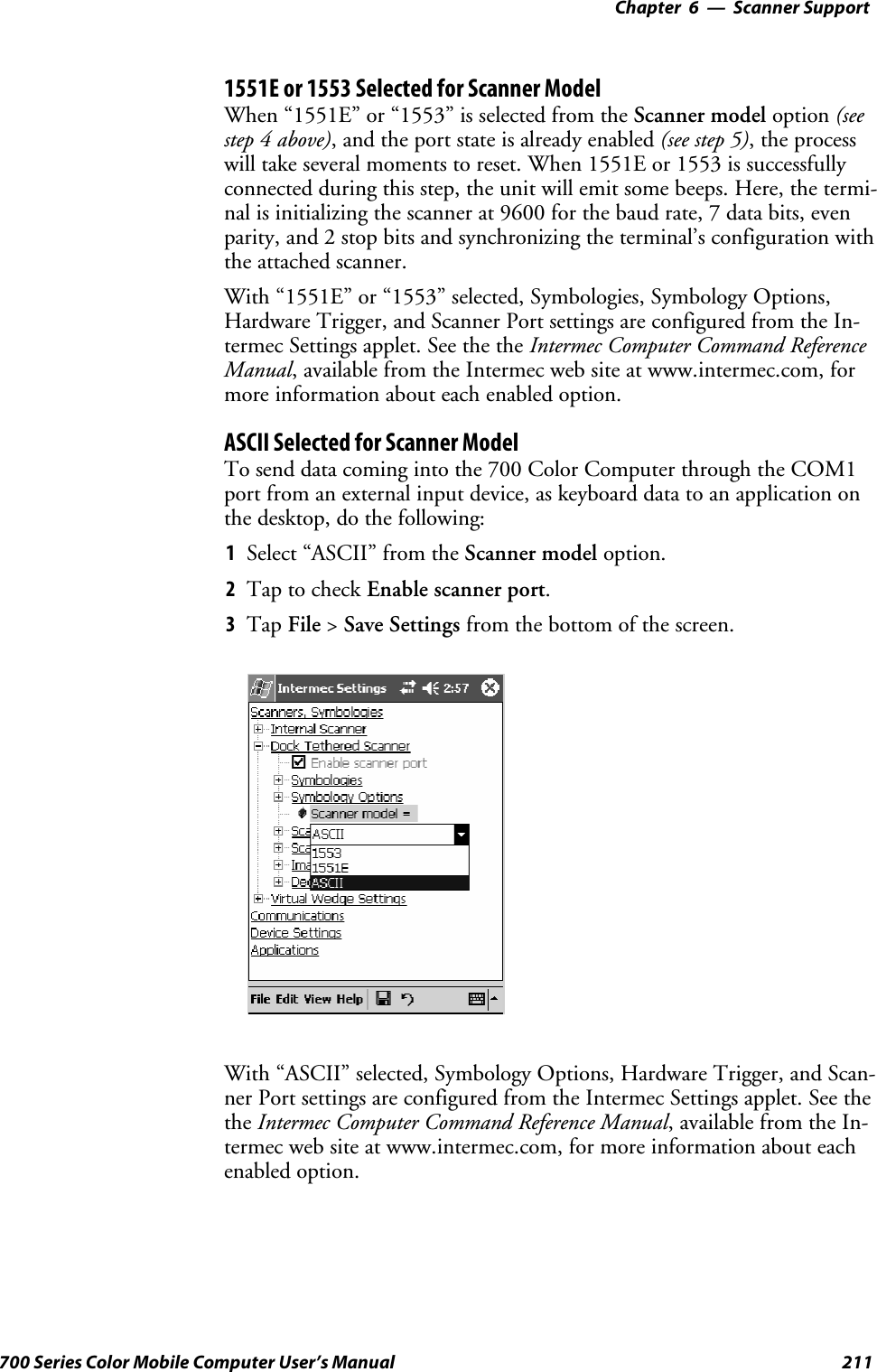
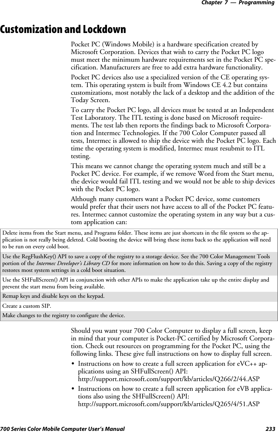
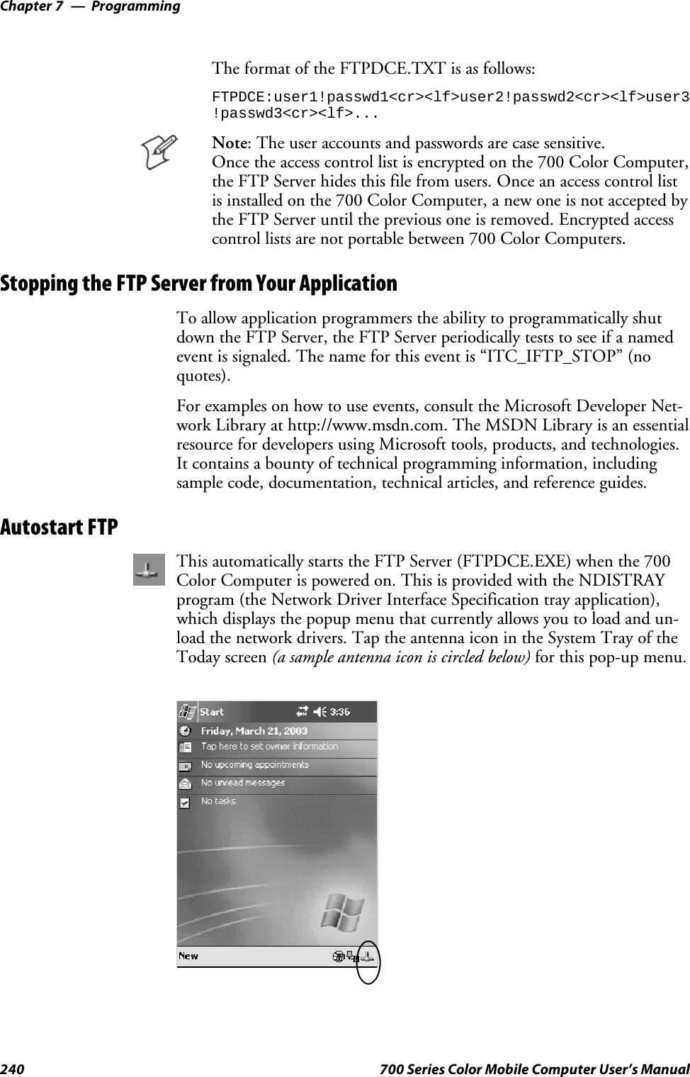
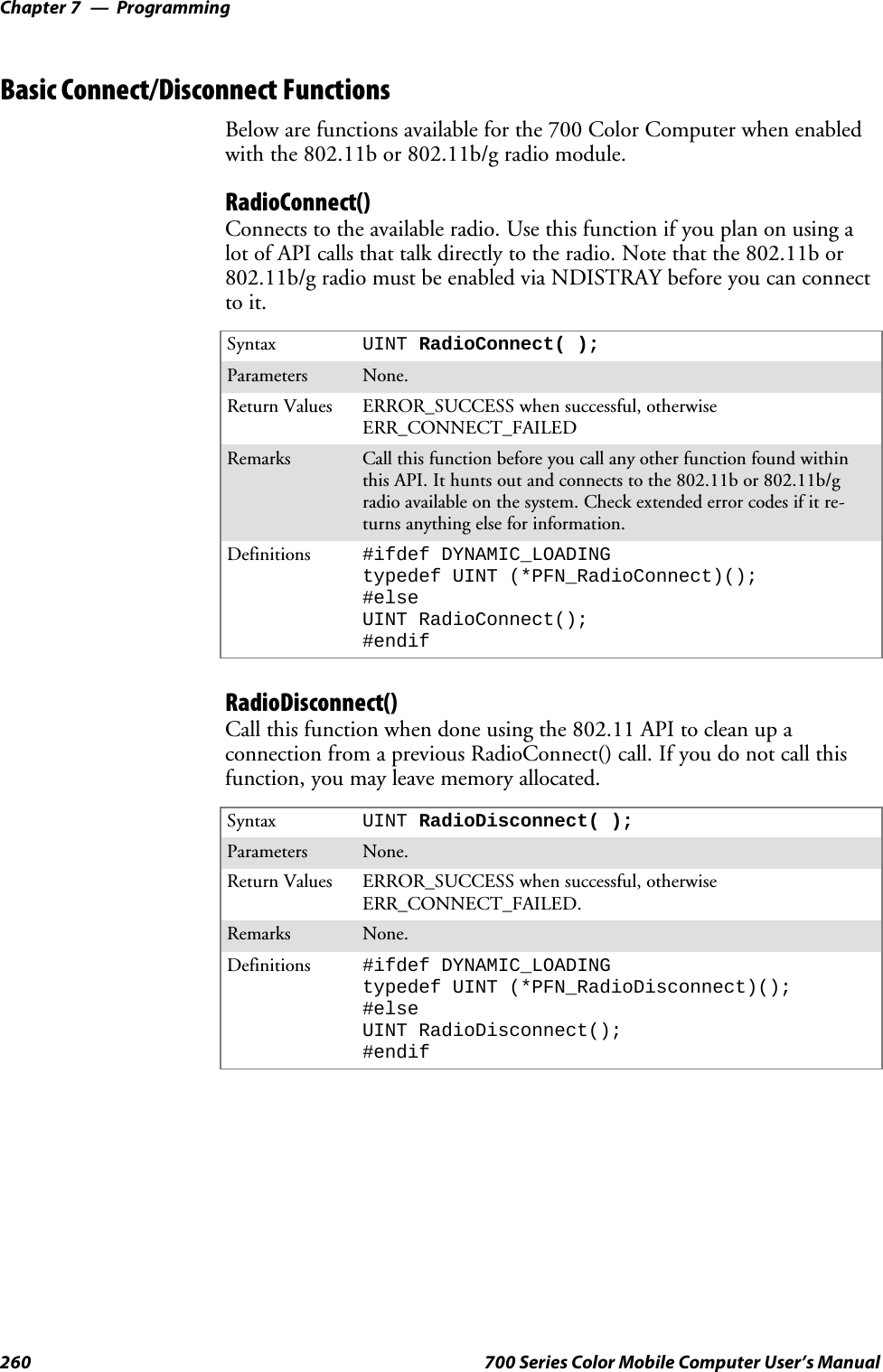
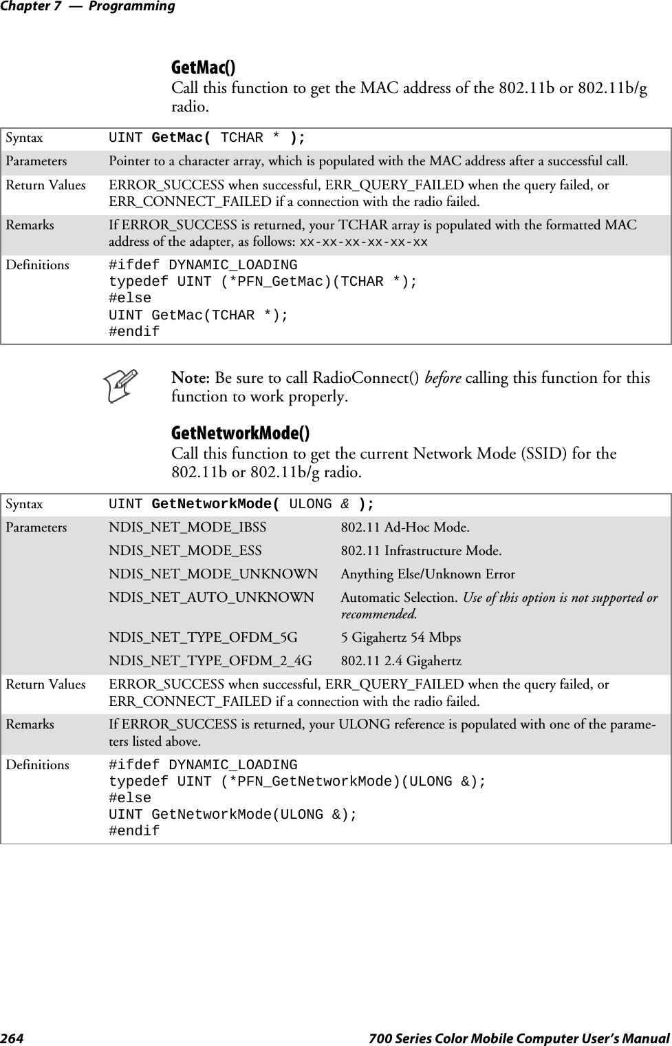
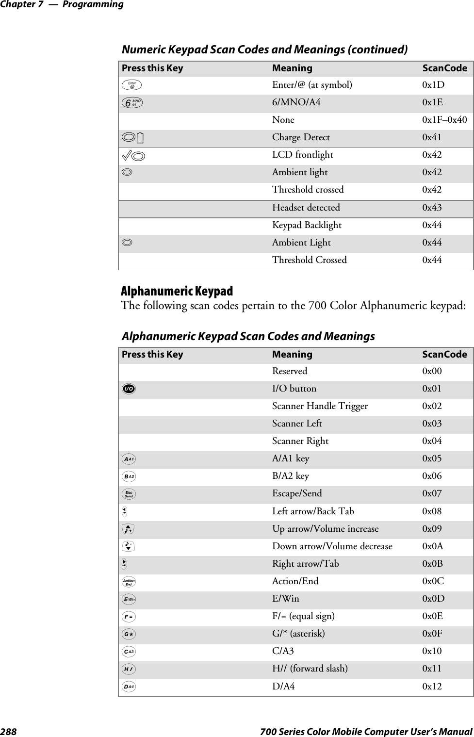
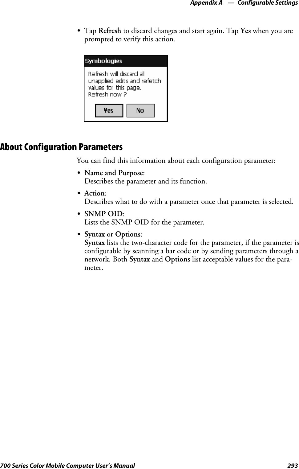
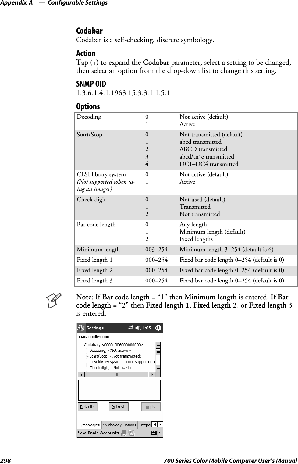
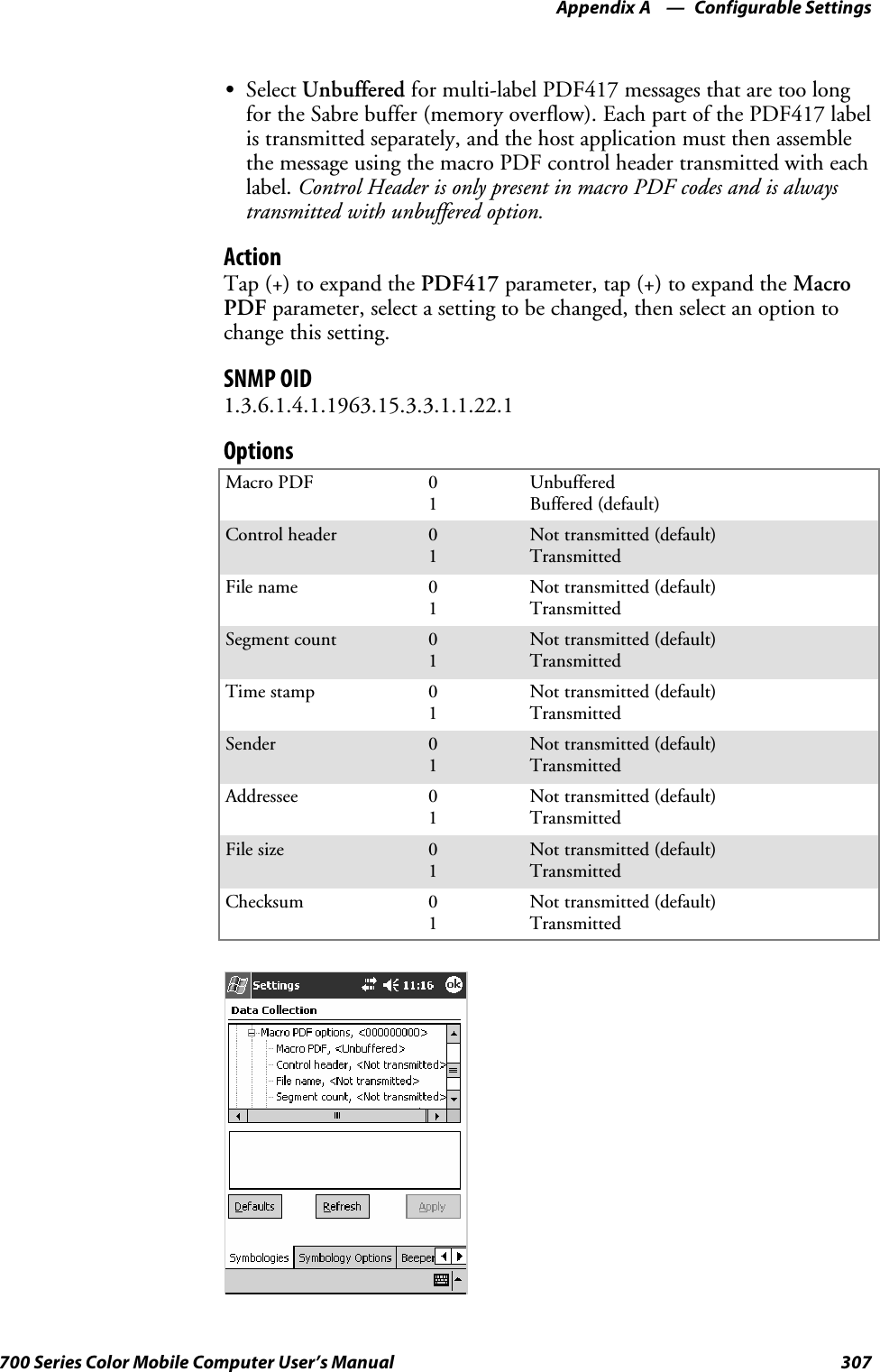
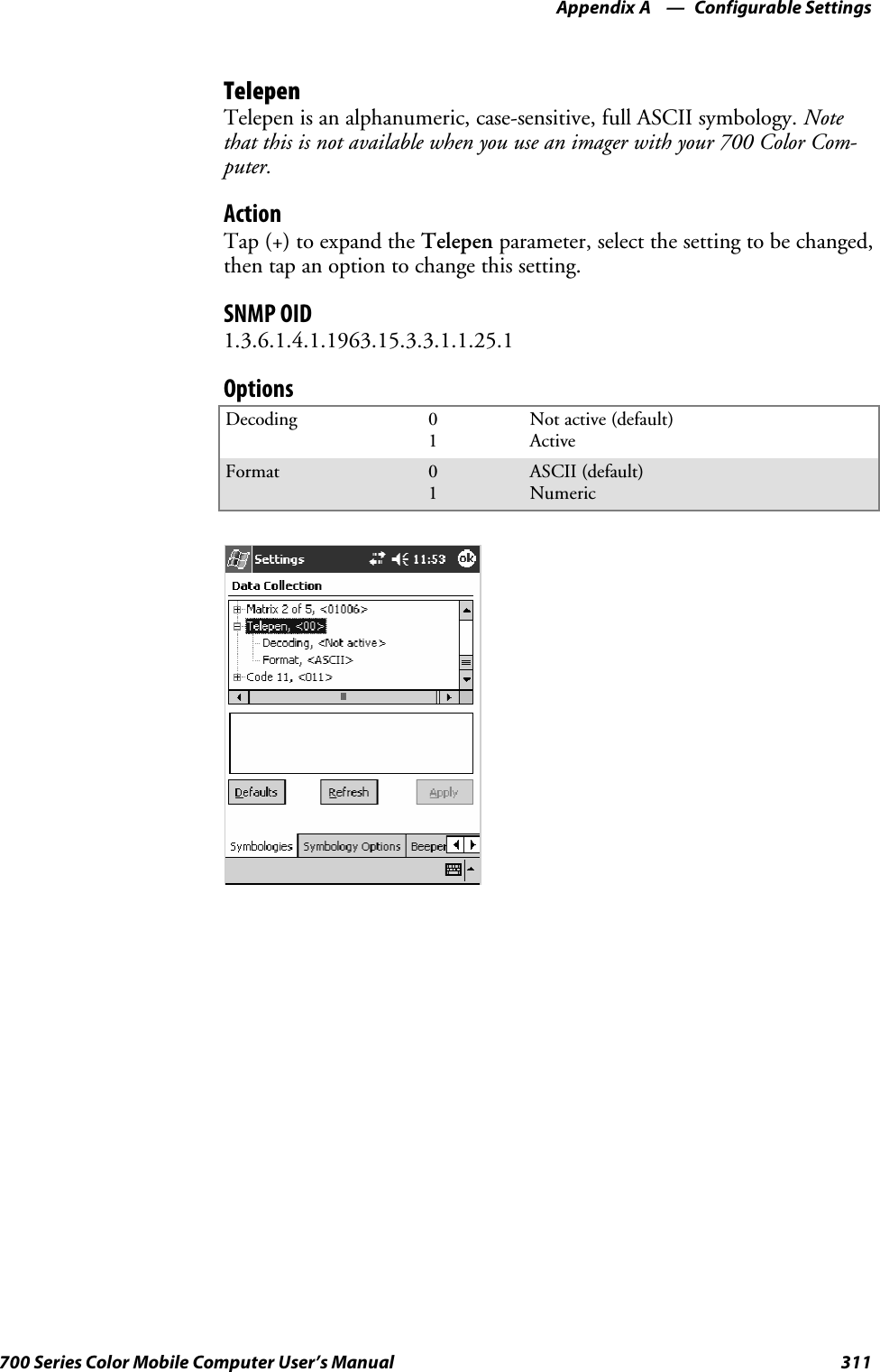
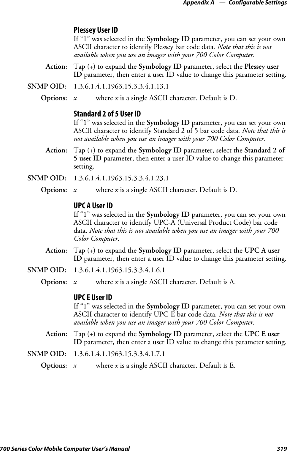
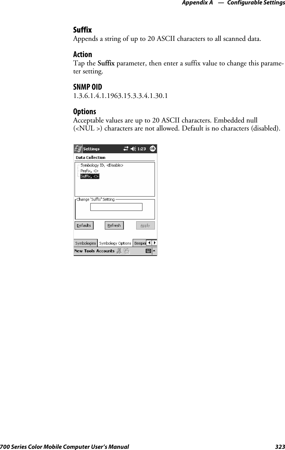
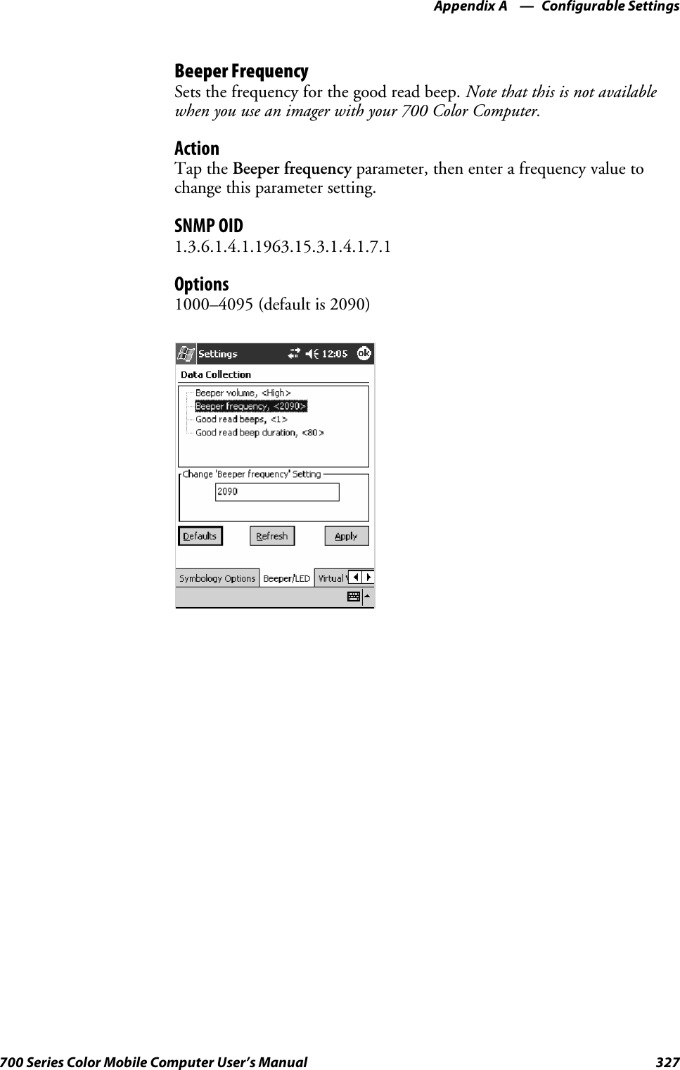
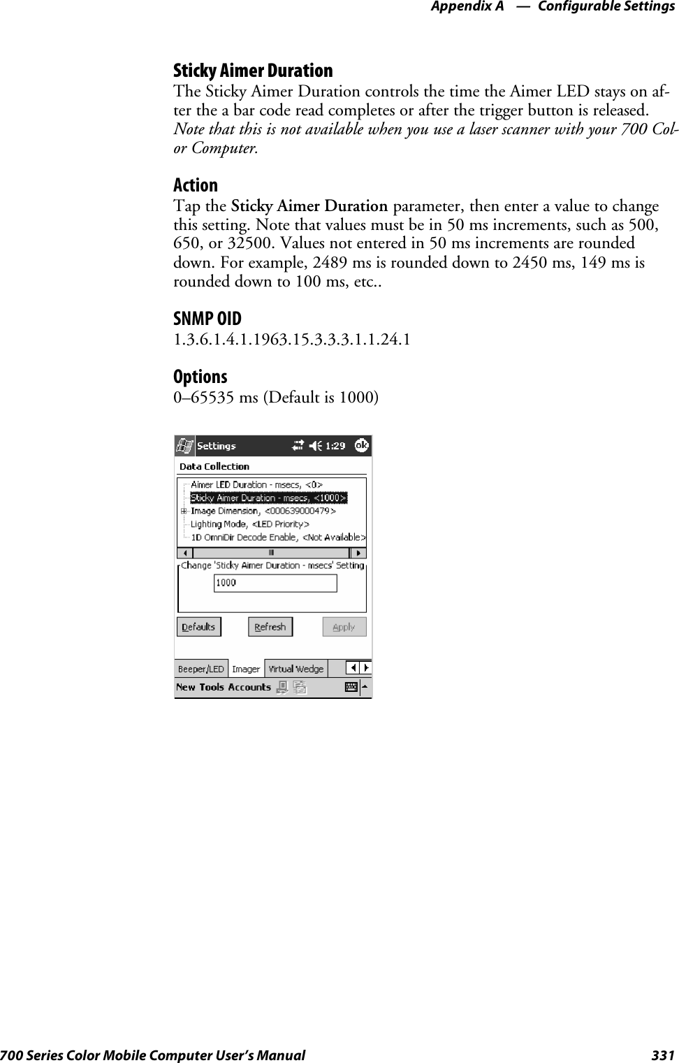
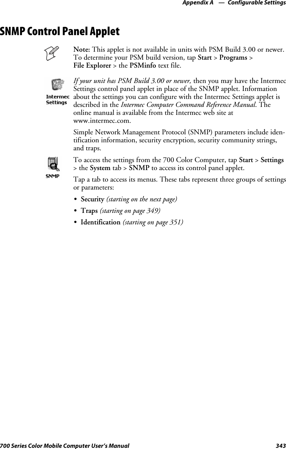
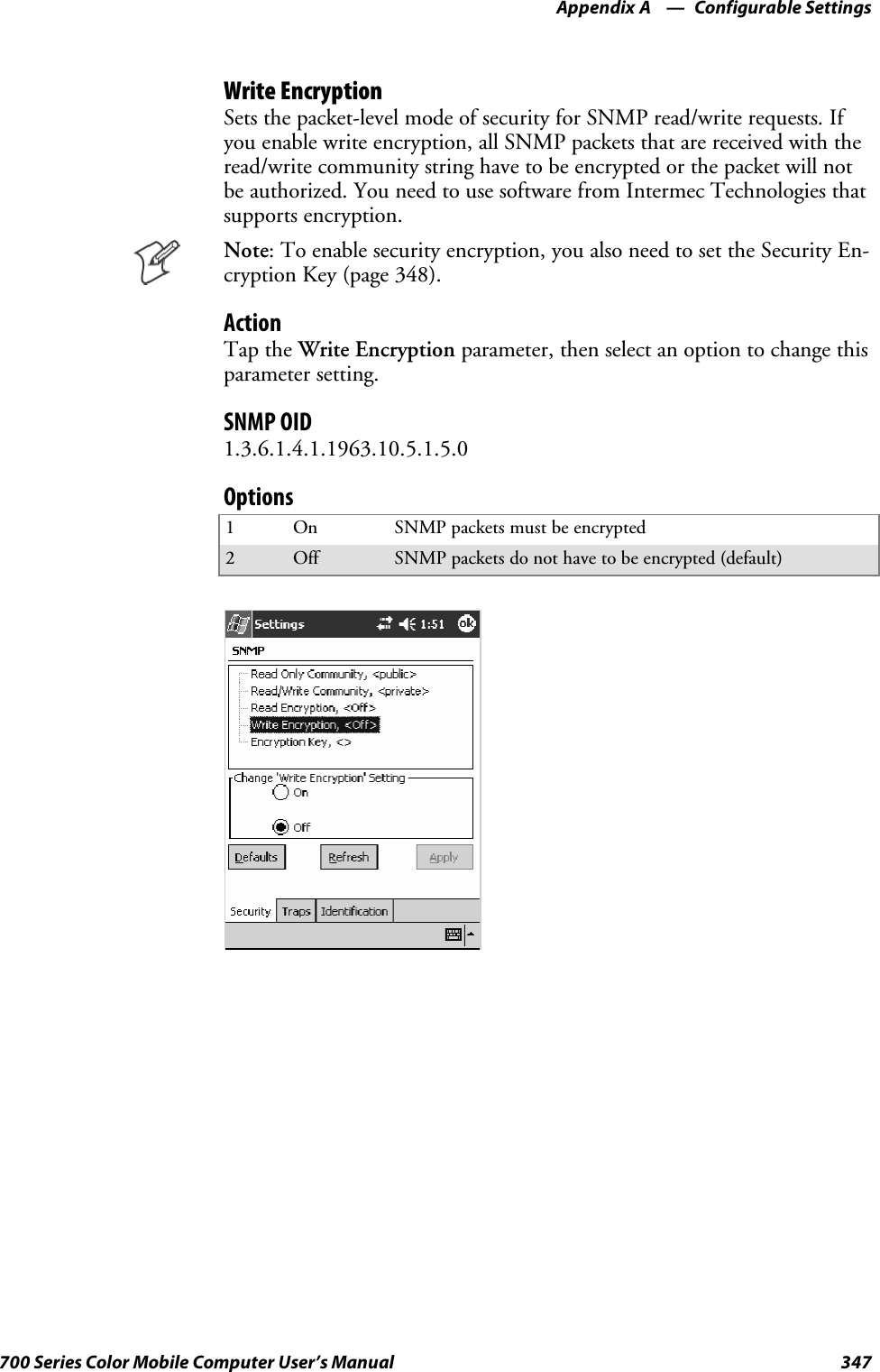
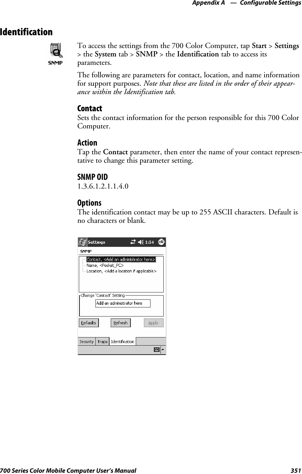
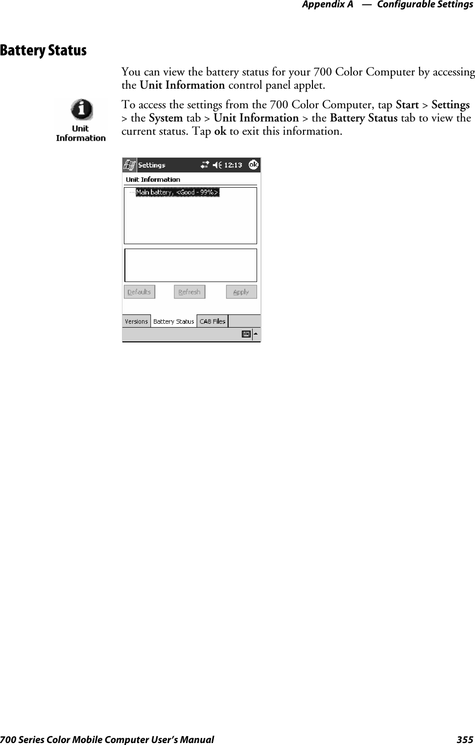
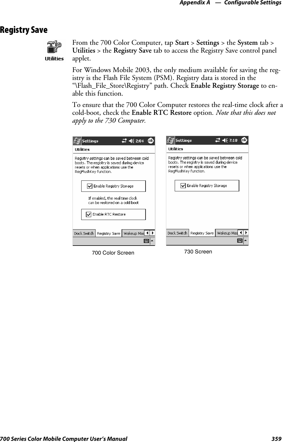
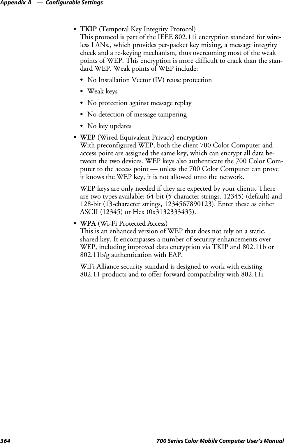
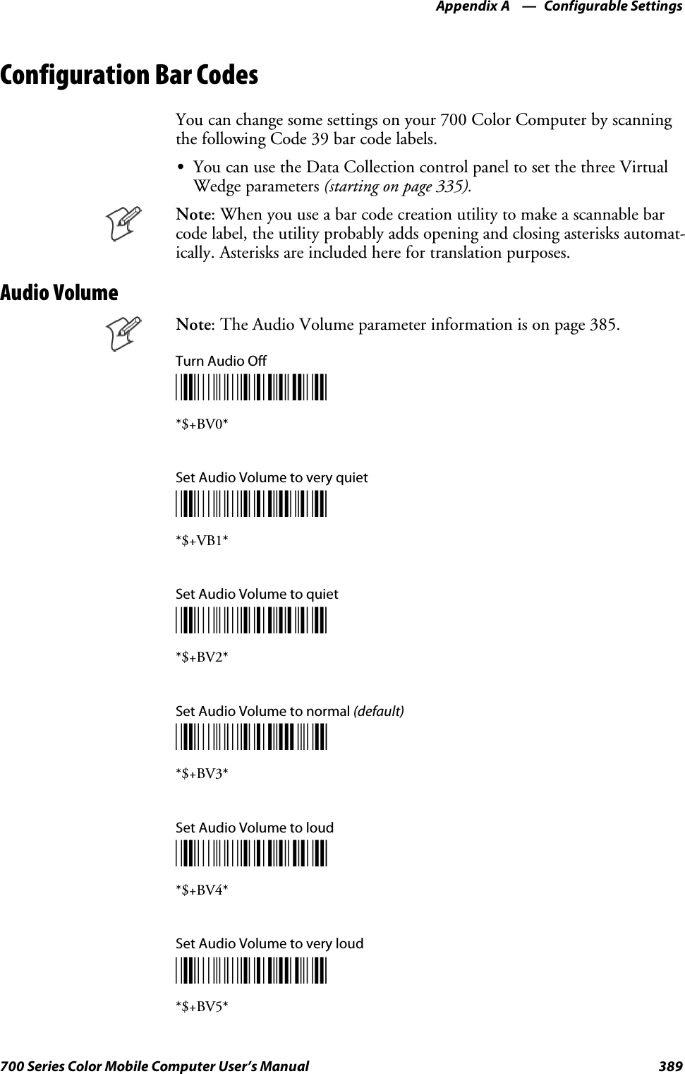
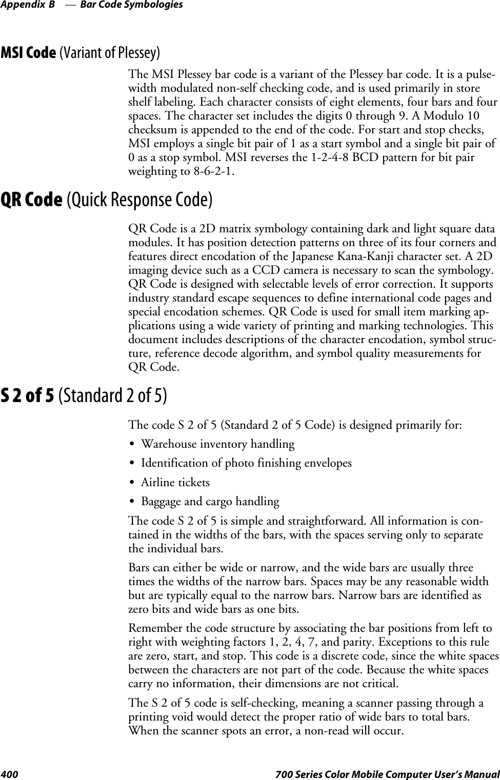
![IntroductionChapter —114 700 Series Color Mobile Computer User’s ManualAlpha (Blue) Plane KeysThe alphabet can be entered with either the numeric keypad or the alpha-numeric keypad. Below and on the next page are the key sequences.Numeric KeypadWhen you press F, the Scanning/Alpha LED (C)shows‘red’forthe Alpha mode. The keypad stays in Alpha mode until you press F.To type a lowercase ‘c,’ press F222(the [2] key threetimes). To type a letter on the same key as the last letter entered, wait twoseconds, then enter the correct series of keystrokes to create the next letter.WhileyouareintheAlphamodeandyoupress1to initiate the CAPSmode, you will render a CAPS LOCK until you press 1again. Onceyou are in CAPS mode, you stay in CAPS until it is pressed again.Press 0to enter a space.To Enter Press the Keys To Enter Press the KeysaF2 AF12bF22 BF122cF222 CF1222dF3 DF13eF33 EF133fF333 FF1333gF4 GF14hF44 HF144iF444 IF1444jF5 JF15kF55 KF155lF555 LF1555mF6 MF16nF66 NF166oF666 OF1666pF7 PF17qF77 QF177rF777 RF1777sF7777 SF17777tF8 TF18uF88 UF188vF888 VF1888wF9 WF19xF99 XF199yF999 YF1999zF9999 ZF19999](https://usermanual.wiki/Intermec-Technologies/2610CF.700C-User-Manual-1-of-3/User-Guide-527885-Page-36.png)
![Printer Support—Chapter 5191700 Series Color Mobile Computer User’s ManualNPCP Printer DriverThe NPCP printer communications driver (NPCPPORT.DLL) is aStream Device Driver built into the operating system. The driver supportsonly NPCP communications to and from the 6820 and 4820 printers overa selected serial port.All applications use WIN32 API functions to access the drivers. Basic op-erations are easily implemented by applications through the CreateFile(),WriteFile(), ReadFile(), DeviceIOControl(), and CloseHandle() Win32APIs.Operations to upgrade printer modules, perform printer diagnostics, andget printer configuration are performed largely via DeviceIOControl()functions.About NPCPNPCP (Norand®Portable Communications Protocol) is a proprietaryprotocol that provides session, network, and datalink services for Intermecmobile computers in the Intermec LAN environment used with printersand data communications.NPCP Driver Installation and RemovalUseLPT9:fortheNPCPprinterdeviceandCOM1forthelastparame-ter. COM1 is the connection available via the 700 Color Computer.Applications use the RegisterDevice() function to install the driver.DeregisterDevice() uninstalls the device driver and frees memory spacewhen the driver is not required. Use the HANDLE returned byRegisterDevice() as the parameter to DeregisterDevice().Use the RegisterDevice() function call as demonstrated below. Specify thefull path name to the driver starting at the root for the RegisterDevice()function to work properly. The last parameter to RegisterDevice() is aDWORD that represents the name of the port for the NPCP streamdriver to use. Build this parameter on the stack if it is not to be paged outduringthecall.Thefirstparameter“LPT”(DeviceName)andthesecondparameter “9’ (index), indicate the name of the registered device, such asLPT9. This is used in the CreateFile() function call.Install(){HANDLE hDevice;TCHAR port[6];port[0] = TCHAR(‘C’);port[1] = TCHAR(‘O’);port[2] = TCHAR(‘M’);port[3] = TCHAR(‘1’);port[4] = TCHAR(‘:’);port[5] = TCHAR(0);hDevice = RegisterDevice ( (TEXT(”LPT”), 9,TEXT(“\\STORAGE CARD\\WINDOWS\\NPCPPORT.dll”), (DWORD)port);}](https://usermanual.wiki/Intermec-Technologies/2610CF.700C-User-Manual-1-of-3/User-Guide-527885-Page-213.png)
![Printer SupportChapter —5196 700 Series Color Mobile Computer User’s ManualO’Neil Printer DriverThe DTR printer communications driver is a Stream Device Drivernamed ONEIL.DLL.All applications use WIN32 API functions to access drivers. Basicoperations are easily implemented by applications through theCreateFile(), WriteFile(), DeviceIOControl() and CloseHandle() Win32APIs.The driver supports communications to 6804DM, 6804T, 6805A, 6806,6808, 681T, and PB20 printers over a selected serial port.DTR Driver Installation and RemovalYour application must install the device driver by using the RegisterDe-vice() function. The driver name is ONEIL.DLL. We recommend thatyou use “DTR” for the Device Name parameter, “1” for the Device Driv-er index parameter, and use any of the following strings for the last param-eter:SNULL (==0) Defaults to COM1 @ 9600S“COM1” only COM port specified defaults to 9600S“COM1:9600” sets to COM port and specified bit rateS“COM1:19200” sets to COM port and specified bit rateUse the HANDLE returned by RegisterDevice() as the parameter toDeregisterDevice(). The correct usage of the RegisterDevice() function callis demonstrated below. You may use DeregisterDevice() to uninstall thedriver.Install(){HANDLE hDevice;TCHAR port[6];port[0] = TCHAR(‘C’);port[1] = TCHAR(‘O’);port[2] = TCHAR(‘M’);port[3] = TCHAR(‘1’);port[4] = TCHAR(‘:’);port[5] = TCHAR(0);hDevice = RegisterDevice ( (TEXT(”DTR”), 1, TEXT(”\\WINDOWS\\ONEIL.DLL”),(DWORD)port);}](https://usermanual.wiki/Intermec-Technologies/2610CF.700C-User-Manual-1-of-3/User-Guide-527885-Page-218.png)

![Scanner SupportChapter —6208 700 Series Color Mobile Computer User’s ManualSThe bar code APIs, defined in the IADC interface, are available to getbarcodedatafromthebarcodescanner.Thefollowingexampleshowshow to programmatically collects bar code data:#include “IADC.h” // Linked with ITCUUID.LIB#include “ITCAdcMgmt.h” // Linked with ITCAdcDevMgmt.libIADC* pIADC;HRESULT hrStatus = S_OK;// Create a ADC COM interface to collect bar code data from the 1551E/1553// when the 1551/1553 menu option is enabled.hrStatus =ITCDeviceOpen(TEXT(“ExtScanner”), // Name of the ADC device.IID_IADC, // COM interface to returnITC_DHDEVFLAG_READAHEAD, // Device’s Flags(LPVOID *) &pIADC); // the returned interfaceif( SUCCEEDED(hrStatus) ){BYTE byteBuffer[MAX_LABEL_SIZE];DWORD dwLength = 0;HRESULT hr = pIDC->Read(byteBuffer, // Buffer to put the ADC data.MAX_LABEL_SIZE, // Size of pDataBuffer in bytes.&dwLength, // Number bytes returned.NULL, // Time stamp of the received data. NULL.INFINITE // Number of milliseconds to wait.);}when done using this COM interface, delete it:ITCDeviceClose( (IUnknown **) pIADC);](https://usermanual.wiki/Intermec-Technologies/2610CF.700C-User-Manual-1-of-3/User-Guide-527885-Page-230.png)

![ProgrammingChapter —7216 700 Series Color Mobile Computer User’s ManualCreating CAB FilesThe Windows CE operating system uses a .CAB file to install an applica-tion on a Windows CE-based device. A .CAB file is composed of multiplefiles that are compressed into one file. Compressing multiple files into onefile provides the following benefits:SAll application files are present.SA partial installation is prevented.SThe application can be installed from several sources, such as a desktopcomputer or a Web site.Use the CAB Wizard application (CABWIZ.EXE) to generate a .CAB fileforyourapplication.Creating Device-Specific CAB FilesDo the following to create a device-specific .CAB file for an application, inthe order provided:1Create an .INF file with Windows CE-specific modifications (page216).2Optional Create a SETUP.DLL file to provide custom control of theinstallation process (page 228).3UsetheCABWizardtocreatethe.CABfile,usingthe.INFfile,theoptional SETUP.DLL file, and the device-specific application files asparameters (page 231).Creating an .INF FileAn .INF file specifies information about an application for the CAB Wi-zard. Below are the sections of an .INF file:[Version]This specifies the creator of the file, version, and other relevant informa-tion.Required? YesSSignature:“signature_name”“$Windows NT$”SProvider:“INF_creator”The company name of the application, such as “Microsoft.”SCESignature“$Windows CE$”Example[Version]Signature = “$Windows NT$”Provider = “Intermec”CESignature = “$Windows CE$”](https://usermanual.wiki/Intermec-Technologies/2610CF.700C-User-Manual-1-of-3/User-Guide-527885-Page-238.png)
![Programming—Chapter 7217700 Series Color Mobile Computer User’s Manual[CEStrings]This specifies string substitutions for the application name and the defaultinstallation directory.Required? YesSAppName:app_nameName of the application. Other instances of %AppName% in the .INFfile are replaced with this string value, such as RP32.SInstallDir:default_install_dirDefault installation directory on the device. Other instances of %Install-Dir% in the .INF file are replaced with this string value. Example:\SDMMC_Disk\%AppName%Example[CEStrings]AppName=“Game Pack”InstallDir=%CE1%\%AppName%[Strings]This section is optional and defines one or more string keys. A string keyrepresents a string of printable characters.Required? NoSstring_key:valueString consisting of letters, digits, or other printable characters. Enclosevalue in double quotation marks ““”” if the corresponding string key isused in an item that requires double quotation marks. No string_keys isokay.Example[Strings]reg_path = Software\Intermec\My Test App](https://usermanual.wiki/Intermec-Technologies/2610CF.700C-User-Manual-1-of-3/User-Guide-527885-Page-239.png)
![ProgrammingChapter —7218 700 Series Color Mobile Computer User’s Manual[CEDevice]Describes the platform for the targeted application. All keys in this sectionare optional. If a key is nonexistent or has no data, Windows CE does notperform any checking with the exception being UnsupportedPlatforms.Ifthe UnsupportedPlatforms key exists but no data, the previous value is notoverridden.Required? YesSProcessorType :processor_typeThe value that is returned by SYSTEMINFO.dwProcessorType.Forexample, the value for the ARM CPU is 2577SUnsupportedPlatforms:platform_family_nameThis lists known unsupported platform family names. If the namespecified in the [CEDevice.xxx] section is different from that in the[CEDevice] section, both platform_family_name values are unsupportedfor the microprocessor specified by xxx. That is, the list of unsupportedplatform family names is appended to the previous list of unsupportednames. Application Manager will not display the application for anunsupported platform. Also, a user will be warned during the setupprocess if the .CAB file is copied to an unsupported device.Example[CEDevice]UnsupportedPlatforms = pltfrm1 ; pltfrm1 is unsupported[CEDevice.SH3]UnsupportedPlatforms = ; pltfrm1 is still unsupportedSVersionMin:minor_versionNumeric value returned by OSVERSIONINFO.dwVersionMinor. The.CAB file is valid for the currently connected device if the version ofthis device is greater than or equal to VersionMin.SVersionMax:major_versionNumeric value returned by OSVERSIONINFO.dwVersionMajor. The.CAB file is valid for the currently connected device if the version ofthis device is less than or equal to VersionMax.SBuildMin:build_numberNumeric value returned by OSVERSIONINFO.dwBuildNumber. The.CAB file is valid for the currently connected device if the version ofthis device is greater than or equal to BuildMin.SBuildMax:build_numberNumeric value returned by OSVERSIONINFO.dwBuildNumber. The.CAB file is valid for the currently connected device if the version ofthis device is less than or equal to BuildMax.](https://usermanual.wiki/Intermec-Technologies/2610CF.700C-User-Manual-1-of-3/User-Guide-527885-Page-240.png)
![Programming—Chapter 7219700 Series Color Mobile Computer User’s ManualExampleThe following code example shows three [CEDevice] sections: one thatgives basic information for any CPU and two that are specific to the SH3and the MIPS microprocessors.[CEDevice] ; A “template” for all platformsUnsupportedPlatforms = pltfrm1 ; Does not support pltfrm1; The following specifies version 1.0 devices only.VersionMin = 1.0VersionMax = 1.0[CEDevice.ARM] ; Inherits all [CEDevice] settings; This will create a .CAB file specific to ARM devices.ProcessorType = 2577 ; ARM .cab file is valid for ARM microprocessors.UnsupportedPlatforms = ; pltfrm1 is still unsupported; The following overrides the version settings so that no version checking isperformed.VersionMin =VersionMax =[CEDevice.MIPS] ; Inherits all [CEDevice] settings; This will create a .CAB file specific to “MIPS” devices.ProcessorType = 4000 ; MIPS .CAB file is valid for MIPSmicroprocessor.UnsupportedPlatforms =pltfrm2 ; pltfrm1,pltfrm2 unsupported for MIPs .CABfile.Note:TocreatethetwoCPU-specific.CABfilesfortheSETUP.INFfilein the previous example, run the CAB Wizard with the “/cpu arm mips”parameter.](https://usermanual.wiki/Intermec-Technologies/2610CF.700C-User-Manual-1-of-3/User-Guide-527885-Page-241.png)
![ProgrammingChapter —7220 700 Series Color Mobile Computer User’s Manual[DefaultInstall]This describes the default installation of your application. Note that underthis section, you will list items expanded upon later in this description.Required? YesSCopyfiles:copyfile_list_sectionMaps to files defined later in the .INF file, such as Files.App, Files.Font,and Files.Bitmaps.SAddReg:add_registry_sectionExample: RegSettings.AllSCEShortcuts:shortcut_list_sectionString that identifies one more section that defines shortcuts to a file, asdefined in the [CEShortcuts] section.SCESetupDLL:setup_DLLOptimal string that specifies a SETUP.DLL file. It is written by the In-dependent Software Vendor (ISV) and contains customized functionsfor operations during installation and removal of the application. Thefile must be specified in the [SourceDisksFiles] section.SCESelfRegister:self_reg_DLL_filenameString that identifies files that self-register by exporting the DllRegister-Server and DllUnregisterServer Component Object Model (COM)functions. Specify these files in the [SourceDiskFiles] section. Duringinstallation, if installation on the device fails to call the file’s exportedDllRegisterServer function, the file’s exported DllUnregisterServerfunction will not be called during removal.Example[DefaultInstall]AddReg = RegSettings.AllCEShortcuts = Shortcuts.All[SourceDiskNames]This section describes the name and path of the disk on which your ap-plication resides.Required? YesSdisk_ordinal:disk_label,,path1=,“App files” , C:\Appsoft\RP32\...2=,“Font files”,,C:\RpTools\...3=,“CE Tools” ,,C:\windows ce tools...SCESignature: “$Windows CE$”Example[SourceDisksNames] ; Required section1 = ,“Common files”,,C:\app\common ; Using an absolute path[SourceDisksNames.SH3]2 = ,“SH3 files”,,sh3 ; Using a relative path[SourceDisksNames.MIPS]2 = ,“MIPS files”,,mips ; Using a relative path](https://usermanual.wiki/Intermec-Technologies/2610CF.700C-User-Manual-1-of-3/User-Guide-527885-Page-242.png)
![Programming—Chapter 7221700 Series Color Mobile Computer User’s Manual[SourceDiskFiles]This describes the name and path of the files in which your applicationresides.Required? YesSfilename:disk_number[,subdir]RPM.EXE = 1,c:\appsoft\...WCESTART.INI = 1RPMCE212.INI = 1TAHOMA.TTF = 2Note:[,subdir] is relative to the location of the INF file.Example[SourceDisksFiles] ; Required sectionbegin.wav = 1end.wav = 1sample.hlp = 1[SourceDisksFiles.SH3]sample.exe = 2 ; Uses the SourceDisksNames.SH3 identification of 2.[SourceDisksFiles.MIPS]sample.exe = 2 ; Uses the SourceDisksNames.MIPS identification of 2.](https://usermanual.wiki/Intermec-Technologies/2610CF.700C-User-Manual-1-of-3/User-Guide-527885-Page-243.png)
![ProgrammingChapter —7222 700 Series Color Mobile Computer User’s Manual[DestinationDirs]This describes the names and paths of the destination directories for theapplication on the target device. Note Windows CE does not support directo-ry identifiers.Required? YesSfile_list_section:0,subdirString that identifies the destination directory. The following list showsthe string substitutions supported by Windows CE. Use these only forthe beginning of the path. \%CE1% \Program Files%CE2% \Windows%CE3% \My Documents%CE4% \Windows\Startup%CE5% \My Documents%CE6% \Program Files\Accessories%CE7% \Program Files\Communication%CE8% \Program Files\Games%CE9% \Program Files\Pocket Outlook%CE10% \Program Files\Office%CE11% \Windows\Start Menu\Programs%CE12% \Windows\Start Menu\Programs\Accessories%CE13% \Windows\Start Menu\Programs\Communications%CE14% \Windows\Start Menu\Programs\Games%CE15% \Windows\Fonts%CE16% \Windows\Recent%CE17% \Windows\Start Menu%InstallDir%Contains the path to the target directory selected during installation. Itis declared in the [CEStrings] section%AppName%Contains the application name defined in the [CEStrings] section.Example[DestinationDirs]Files.Common = 0,%CE1%\My Subdir ; \Program Files\My SubdirFiles.Shared = 0,%CE2% ; \Windows](https://usermanual.wiki/Intermec-Technologies/2610CF.700C-User-Manual-1-of-3/User-Guide-527885-Page-244.png)
![Programming—Chapter 7223700 Series Color Mobile Computer User’s Manual[CopyFiles]This section, under the [DefaultInstall] section, describes the default filesto copy to the target device. Within the [DefaultInstall] section, files werelisted that must be defined elsewhere in the INF file. This section identi-fies that mapping and may contain flags.Required? YesScopyfile_list_section:destination_filename,[source_filename]The source_filename parameter is optional if it is the same as destina-tion_filename.Scopyfile_list_section:flagsThenumericvaluethatspecifiesanactiontobedonewhilecopyingfi-les. The following table shows values supported by Windows CE.Flag Value DescriptionCOPYFLG_WARN_IF_SKIP 0x00000001 Warn user if skipping a file is attempted after error.COPYFLG_NOSKIP 0x00000002 Do not allow a user to skip copying a file.COPYFLG_NO_OVERWRITE 0x00000010 Do not overwrite files in destination directory.COPYFLG_REPLACEONLY 0x00000400 Copy the source file to the destination directory only if thefile is already in the destination directory.CE_COPYFLG_NO_DATE_DIALOG 0x20000000 Do not copy files if the target file is newer.CE_COPYFLG_NODATECHECK 0x40000000 Ignore date while overwriting the target file.CE_COPYFLG_SHARED 0x80000000 Create a reference when a shared DLL is counted.Example[DefaultInstall.SH3]CopyFiles = Files.Common, Files.SH3[DefaultInstall.MIPS]CopyFiles = Files.Common, Files.MIPS](https://usermanual.wiki/Intermec-Technologies/2610CF.700C-User-Manual-1-of-3/User-Guide-527885-Page-245.png)
![ProgrammingChapter —7224 700 Series Color Mobile Computer User’s Manual[AddReg]This section, under the [DefaultInstall] section, is optional and describesthe keys and values that the .CAB file adds to the device registry. Withinthe [DefaultInstall] section, a reference may have been made to thissection, such as “AddReg=RegSettings.All”. This section defines theoptions for that setting.Required? NoSadd_registry_section:registry_root_stringString that specifies the registry root location. The following list showsthevaluessupportedbyWindowsCE.SHKCR Same as HKEY_CLASSES_ROOTSHKCU Same as HKEY_CURRENT_USERSHKLM Same as HKEY_LOCAL_MACHINESadd_registry_section:value_nameRegistryvaluename.Ifempty,the“default”registryvaluenameisused.Sadd_registry_section:flagsNumeric value that specifies information about the registry key. Thefollowing table shows the values that are supported by Window CE.Flag Value DescriptionFLG_ADDREG_NOCLOBBER 0x00000002 If the registry key exists, do not overwrite it. Can be usedwith any of the other flags in this table.FLG_ADDREG_TYPE_SZ 0x00000000 REG_SZ registry data type.FLG_ADDREG_TYPE_MULTI_SZ 0x00010000 REG_MULTI_SZ registry data type. Value field that followscan be a list of strings separated by commas.FLG_ADDREG_TYPE_BINARY 0x00000001 REG_BINARY registry data type. Value field that followsmust be a list of numeric values separated by commas, onebyte per field, and must not use the 0x hexadecimal prefix.FLG_ADDREG_TYPE_DWORD 0x00010001 REG_DWORD data type. The noncompatible format in theWin32 Setup .INF documentation is supported.ExampleAddReg = RegSettings.All[RegSettings.All]HKLM,%reg_path%,,0x00000000,alpha ; <default> = “alpha”HKLM,%reg_path%,test,0x00010001,3 ; Test = 3HKLM,%reg_path%\new,another,0x00010001,6 ; New\another = 6](https://usermanual.wiki/Intermec-Technologies/2610CF.700C-User-Manual-1-of-3/User-Guide-527885-Page-246.png)
![Programming—Chapter 7225700 Series Color Mobile Computer User’s Manual[CEShortCuts]This section, a Windows CE-specific section under the [DefaultInstall]section, is optional and describes the shortcuts that the installation applica-tion creates on the device. Within the [DefaultInstall] section, a referencemay have been made to this section, such as “ShortCuts.All”. This sectiondefines the options for that setting.Required? NoSshortcut_list_section:shortcut_filenameString that identifies the shortcut name. It does not require the .LNKextension.Sshortcut_list_section:shortcut_type_flagNumeric value. Zero or empty represents a shortcut to a file; any non-zero numeric value represents a shortcut to a folder.Sshortcut_list_section:target_file_pathString value that specifies the destination location. Use the target filename for a file, such as MyApp.exe, that must be defined in a file copylist. For a path, use a file_list_section name defined in the [Destination-Dirs] section, such as DefaultDestDir,orthe%InstallDir% string.Sshortcut_list_section:standard_destination_pathOptional string value. A standard %CEx% path or %InstallDir%.Ifnovalue is specified, the shortcut_list_section name of the current section orthe DefaultDestDir value from the [DestinationDirs] section is used.ExampleCEShortcuts = Shortcuts.All[Shortcuts.All]Sample App,0,sample.exe ; Uses the path in DestinationDirs. SampleApp,0,sample.exe,%InstallDir% ; The path is explicitly specified.Sample .INF File[Version] ; Required sectionSignature = “$Windows NT$”Provider = “Intermec Technologies Corporation”CESignature = “$Windows CE$”;[CEDevice];ProcessorType =[DefaultInstall] ; Required sectionCopyFiles = Files.App, Files.Fonts, Files.BitMaps, Files.Intl,Files.TelecomNcsCE, Files.Windows, Files.Import, Files.Export, Files.Work,Files.Database, Files.WinCE AddReg = RegSettings.All ;CEShortcuts =Shortcuts.All[SourceDisksNames] ; Required section1 = ,“App files” ,,c:\appsoft\...2 = ,”Font files” ,,c:\WinNT\Fonts3 = ,”CE Tools” ,,c:\windows ce tools\wce400\700ie\mfc\lib\x86[SourceDisksFiles] ; Required sectionrpm.exe = 1,C:\Appsoft\program\wce400\WCEX86Rel700wcestart.ini = 1](https://usermanual.wiki/Intermec-Technologies/2610CF.700C-User-Manual-1-of-3/User-Guide-527885-Page-247.png)
![ProgrammingChapter —7226 700 Series Color Mobile Computer User’s Manualrpmce212.ini = 1intermec.bmp = 1rpmlogo.bmp = 1rpmname.bmp = 1import.bmp = 1export.bmp = 1clock.bmp = 1printer.bmp = 1filecopy.bmp = 1readme.txt = 1lang_eng.bin = 1rpmdata.dbd = 1,database\wce1tahoma.ttf = 2mfcce212.dll = 3olece212.dll = 3olece211.dll = 1,c:\windows ce tools\wce400\NMSD61102.11\mfc\lib\x86rdm45wce.dll = 1,c:\rptools\rdm45wce\4_50\lib\wce400\wcex86relpicfmt.dll = 1,c:\rptools\picfmt\1_00\wce400\wcex86rel6110fmtctrl.dll = 1,c:\rptools\fmtctrl\1_00\wce400\wcex86rel6110ugrid.dll = 1,c:\rptools\ugrid\1_00\wce400\wcex86rel6110simple.dll = 1,c:\rptools\pspbm0c\1_00\wce400\wcex86relpsink.dll = 1,c:\rptools\psink\1_00\wce400\WCEX86RelMinDependencypslpwce.dll =1,c:\rptools\pslpm0c\1_00\wce400\WCEX86RelMinDependencynpcpport.dll = 1,c:\rptools\cedk\212_03\installable drivers\printer\npcp;dexcom.dll = 1,c:\rptools\psdxm0c\1_00\x86ncsce.exe = 1,c:\rptools\ncsce\1_04nrinet.dll = 1,c:\rptools\ncsce\1_04[DestinationDirs] ; Required section;Shortcuts.All = 0,%CE3% ; \Windows\DesktopFiles.App = 0,%InstallDir%Files.DataBase = 0,%InstallDir%\DataBaseFiles.BitMaps = 0,%InstallDir%\BitmapsFiles.Fonts = 0,%InstallDir%\FontsFiles.Intl = 0,%InstallDir%\IntlFiles.TelecomNcsCE = 0,%InstallDir%\Telecom\NcsCEFiles.Windows = 0,%InstallDir%\WindowsFiles.Import = 0,%InstallDir%\ImportFiles.Export = 0,%InstallDir%\ExportFiles.Work = 0,%InstallDir%\WorkFiles.WinCE = 0,\storage_card\wince[CEStrings] ; Required sectionAppName = Rp32InstallDir = \storage_card\%AppName%[Strings] ; Optional section;[Shortcuts.All];Sample App,0,sample.exe ; Uses the path in DestinationDirs.;Sample App,0,sample.exe,%InstallDir% ; The path is explicitly specified.[Files.App]rpm.exe,,,0rpm.ini,rpmce212.ini,,0mfcce212.dll,,,0olece212.dll,,,0olece211.dll,,,0rdm45wce.dll,,,0picfmt.dll,,,0](https://usermanual.wiki/Intermec-Technologies/2610CF.700C-User-Manual-1-of-3/User-Guide-527885-Page-248.png)
![Programming—Chapter 7227700 Series Color Mobile Computer User’s Manualfmtctrl.dll,,,0ugrid.dll,,,0simple.dll,,,0psink.dll,,,0pslpwce.dll,,,0npcpport.dll,,,0;dexcom.dll,,,0[Files.DataBase]rpmdata.dbd,,,0[Files.Fonts]tahoma.ttf,,,0[Files.BitMaps]intermec.bmp,,,0rpmlogo.bmp,,,0rpmname.bmp,,,0import.bmp,,,0export.bmp,,,0clock.bmp,,,0printer.bmp,,,0filecopy.bmp,,,0[Files.Intl]lang_eng.bin,,,0[Files.TelecomNcsCE]ncsce.exe,,,0nrinet.dll,,,0[Files.Windows]readme.txt,,,0[Files.Import]readme.txt,,,0[Files.Export]readme.txt,,,0[Files.Work]readme.txt,,,0[Files.WinCE]wcestart.ini,,,0[RegSettings.All]HKLM,”SOFTWARE\Microsoft\Shell\AutoHide”,,0x00010001,1; Autohide the taskbar HKLM,”SOFTWARE\Microsoft\Shell\OnTop”,,0x00010001,0; Shell is not on topHKLM,”SOFTWARE\Microsoft\Clock”,SHOW_CLOCK,0x00010001,0; Clock is not on taskbar](https://usermanual.wiki/Intermec-Technologies/2610CF.700C-User-Manual-1-of-3/User-Guide-527885-Page-249.png)
![ProgrammingChapter —7228 700 Series Color Mobile Computer User’s ManualUsing Installation Functions in SETUP.DLLSETUP.DLL is an optional file that enables you to perform custom opera-tions during installation and removal of your application. The followinglist shows the functions that are exported by SETUP.DLL.Install_Init Called before installation begins. Use this function to check the application version when reinstal-ling an application and to determine if a dependent application is present.Install_Exit Called after installation is complete. Use this function to handle errors that occur during applica-tion installation.Uninstall_Init Called before the removal process begins. Use this function to close the application, if the applica-tion is running.Uninstall_Exit Called after the removal process is complete. Use this function to save database information to afile and delete the database and to tell the user where the user data files are stored and how to rein-stall the application.Note;Use[DefaultInstall] >CESelfRegister (page 220) in the .INF file topoint to SETUP.DLL.After the CAB File ExtractionCab files that need to cause a warm reset after cab extraction will need tocreate the __RESETMEPLEASE__.TXT file in the “\Windows” directory.The preferred method to create this file is within the DllMain portion oftheSETUP.DLLfile.Itlookslikethis:#include <windows.h>#include <Tlhelp32.h>#include <winioctl.h>#include <ce_setup.h> // in the public SDK dir#define IOCTL_TERMINAL_RESET CTL_CODE (FILE_DEVICE_UNKNOWN,FILE_ANY_ACCESS,2050, METHOD_NEITHER)BOOL APIENTRY DllMain( HANDLE h, DWORD reason, LPVOID lpReserved ){return TRUE;} // DllMain//************************************************************************// $DOCBEGIN$// BOOL IsProcessRunning( TCHAR * pname );//// Description: Get process table snapshot, look for pname running.//// Arguments: pname - pointer to name of program to look for.// for example, app.exe.//// Returns: TRUE - process is running.// FALSE - process is not running.// $DOCEND$//************************************************************************BOOL IsProcessRunning( TCHAR * pname ){HANDLE hProcList;](https://usermanual.wiki/Intermec-Technologies/2610CF.700C-User-Manual-1-of-3/User-Guide-527885-Page-250.png)
![Programming—Chapter 7229700 Series Color Mobile Computer User’s ManualPROCESSENTRY32 peProcess;DWORD thDeviceProcessID;TCHAR lpname[MAX_PATH];if ( !pname || !*pname ) return FALSE;_tcscpy( lpname, pname );_tcslwr( lpname );hProcList = CreateToolhelp32Snapshot( TH32CS_SNAPPROCESS, 0 );if ( hProcList == INVALID_HANDLE_VALUE ) {return FALSE;} // end ifmemset( &peProcess, 0, sizeof(peProcess) );peProcess.dwSize = sizeof(peProcess);if ( !Process32First( hProcList, &peProcess ) ) {CloseToolhelp32Snapshot( hProcList );return FALSE;} // end ifthDeviceProcessID = 0;do {_tcslwr( peProcess.szExeFile );if ( _tcsstr( peProcess.szExeFile, lpname ) ) {thDeviceProcessID = peProcess.th32ProcessID;break;} // end if} while ( Process32Next( hProcList, &peProcess ) );if ( ( GetLastError() == ERROR_NO_MORE_FILES ) && ( thDeviceProcessID == 0)){CloseToolhelp32Snapshot( hProcList );return FALSE;} // end ifCloseToolhelp32Snapshot( hProcList );return TRUE;} // IsProcessRunningcodeINSTALL_INIT Install_Init(HWND hwndParent,BOOL fFirstCall,BOOL fPreviouslyInstalled,LPCTSTR pszInstallDir ){return codeINSTALL_INIT_CONTINUE;}codeINSTALL_EXIT Install_Exit (HWND hwndParent,LPCTSTR pszInstallDir,WORD cFailedDirs,WORD cFailedFiles,WORD cFailedRegKeys,](https://usermanual.wiki/Intermec-Technologies/2610CF.700C-User-Manual-1-of-3/User-Guide-527885-Page-251.png)
![ProgrammingChapter —7230 700 Series Color Mobile Computer User’s ManualWORD cFailedRegVals,WORD cFailedShortcuts ){HANDLE h;TCHAR srcfile[MAX_PATH];TCHAR dstfile[MAX_PATH];if (cFailedDirs || cFailedFiles || cFailedRegKeys ||cFailedRegVals || cFailedShortcuts)return codeINSTALL_EXIT_UNINSTALL;if ( IsProcessRunning( L”autocab.exe” ) ){h = CreateFile( L”\\Windows\\__resetmeplease__.txt”,(GENERIC_READ | GENERIC_WRITE), 0, NULL, CREATE_ALWAYS,FILE_ATTRIBUTE_HIDDEN, NULL );if ( h != INVALID_HANDLE_VALUE )CloseHandle( h );else{// Couldn’t create the file. If it failed because the file alreadyexists, it is not fatal.// Otherwise, notify user of the inability to reset the device and theywill have to// perform it manually after all of the installations are complete.} // end if}else{DWORD dret;h = CreateFile( L”SYI1:”,(GENERIC_WRITE | GENERIC_READ), 0, NULL, OPEN_EXISTING,FILE_ATTRIBUTE_NORMAL, NULL );// Force a warm start NOW.if ( h != INVALID_HANDLE_VALUE ){DeviceIoControl( h, IOCTL_TERMINAL_RESET, NULL, 0, NULL, 0, &dret,NULL);// Won’t return, but we’ll show clean up anywayCloseHandle( h );}else{// Couldn’t access SYSIO. Notify user.} // end if} // end ifreturn codeINSTALL_EXIT_DONE;}codeUNINSTALL_INITUninstall_Init(HWND hwndParent,LPCTSTR pszInstallDir ) {](https://usermanual.wiki/Intermec-Technologies/2610CF.700C-User-Manual-1-of-3/User-Guide-527885-Page-252.png)
![Programming—Chapter 7231700 Series Color Mobile Computer User’s Manual// TODO: Perform the reverse of INSTALL_INIT herereturn codeUNINSTALL_INIT_CONTINUE;}codeUNINSTALL_EXITUninstall_Exit(HWND hwndParent) {// TODO: Perform the reverse of INSTALL_EXIT herereturn codeUNINSTALL_EXIT_DONE;}The system software looks for the following directory structure and files ontheinstalledmediacardwhetheritbeanSDcardorCFcardorembeddedflash file system. No other folders need exist.\2577\autorun.exe\2577\autorun.dat\2577\autocab.exe\2577\autocab.dat\cabfiles\*.cabCreating CAB Files with CAB WizardAfter you create the .INF file and the optional SETUP.DLL file, use theCAB Wizard to create the .CAB file. The command-line syntax for theCABWizardisasfollows:cabwiz.exe “inf_file” [/dest dest_directory] [/err error_file] [/cpu cpu_type[cpu_type]]A batch file, located in <program> directory, with the following com-mands, works well:cabwiz.exe c:\appsoft\<program>\<inf_file_name>cd \appsoft\<program>“inf_file” The SETUP.INF file path.dest_directory The destination directory for the .CAB files. If no directory is specified, the .CAB files are createdin the “inf_file” directory.error_file The file name for a log file that contains all warnings and errors that are encountered when the.CAB files are compiled. If no file name is specified, errors are displayed in message boxes. If a filename is used, the CAB Wizard runs without the user interface (UI); this is useful for automatedbuilds.cpu_type Creates a .CAB file for each specified microprocessor tag, which is a label used in the Win32 SE-TUP.INF file to differentiate between different microprocessor types. The /cpu parameter, fol-lowed by multiple cpu_type values, must be the last qualifier in the command line.ExampleThis example creates .CAB files for the ARM and MIPS microprocessors,assuming the Win32 SETUP.INF file contains the ARM and MIPS tags:cabwiz.exe “c:\myfile.inf” /err myfile.err /cpu arm mipsNote: CABWIZ.EXE, MAKECAB.EXE, and CABWIZ.DDF (WindowsCE files available on the Windows CE Toolkit) must be installed in thesame directory on the desktop computer. Call CABWIZ.EXE using its fullpath for the CAB Wizard application to run correctly.](https://usermanual.wiki/Intermec-Technologies/2610CF.700C-User-Manual-1-of-3/User-Guide-527885-Page-253.png)
![ProgrammingChapter —7232 700 Series Color Mobile Computer User’s ManualTroubleshooting the CAB WizardTo identify and avoid problems that might occur when using the CABWizard, follow these guidelines:SUse %% for a percent sign (%) character when using this character inan .INF file string, as specified in Win32 documentation. This will notwork under the [Strings] section.SDo not use .INF or .CAB files created for Windows CE to install ap-plications on Windows-based desktop platforms.SEnsure the MAKECAB.EXE and CABWIZ.DDF files, included withWindows CE, are in the same directory as CABWIZ.EXE.SUse the full path to call CABWIZ.EXE.SDo not create a .CAB file with the MAKECAB.EXE file included withWindows CE. You must use CABWIZ.EXE, which usesMAKECAB.EXE to generate the .CAB files for Windows CE.SDo not set the read-only attribute for .CAB files.](https://usermanual.wiki/Intermec-Technologies/2610CF.700C-User-Manual-1-of-3/User-Guide-527885-Page-254.png)
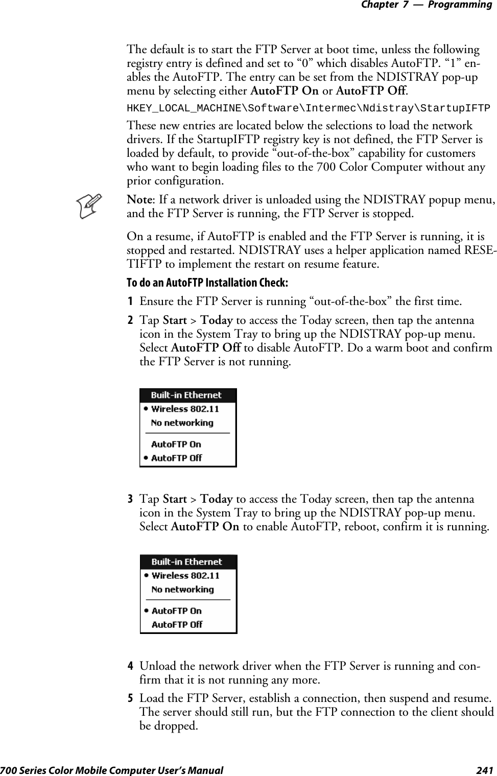
![ProgrammingChapter —7234 700 Series Color Mobile Computer User’s ManualFTP ServerFTP support is provided through the FTP Server applicationFTPDCE.EXE (MS Windows CE Versions) which is provided as part thebase system.FTPDCE is the Internet File Transfer Protocol (FTP) server process. Theserver can be invoked from an application or command line. Besides ser-vicing FTP client requests the FTP Server also send a “network announce-ment” to notify prospective clients of server availability.Note: You should consult the RFC959 specification for proper use ofsome of these commands at the following URL:Shttp://www.ietf.org/rfc/rfc959.txt for the text version, orShttp://www.w3.org/Protocols/rfc959/ for an html versionDo the following to send commands:1Start an FTP client and connect to the device FTP server.2Log in with “intermec” as the user name and “cr52401” for the pass-word.3From the FTP client, send the command.4Wait for a response.Synopsisftpdce [options ]Options–Aaddr (where addr is in the form of a.b.c.d) Sets the single target address to which to send the network an-nouncement. Default is broadcast.–Bbyte Sets the FTP data block size. Smaller sizes may be useful over slower links. Default is 65536.–Cname Sets the device name. Used by Intermec management software.–Fvalue Disables the default Intermec account. A value of “0” disables the account. Default is “1”.Note that disabling the default account without providing a working access control list on the serverwill result in a device that will not accept any FTP connections.–Hsec Sets the interval between network announcements in seconds.A value of “0” turns the network an-nouncement off. Default is 30 seconds.–Iaddr (where addr is in the form of a.b.c.d) Sets the preferred 6920 Communications Server (optional).–Llog (where log is either “0” or “1”) Sets the state of logging. Default is 0 (disabled).–Nsec Specifies the number of seconds to wait before initially starting FTP server services.–Pport Sets the UDP port on which the network announcement will be sent. Default port is 52401.–Qport Sets the port on which the FTP Server will listen for connections. Defaultportis21.–Rdir Sets the FTP mount point to this directory. Default is the root folder of the object store.–Tscrip Sets the script name for the 6920 Communications Server to process.–Uurl Sets the default URL for this device.–Z“parms” Sets extended parameters to be included in the network announcement.](https://usermanual.wiki/Intermec-Technologies/2610CF.700C-User-Manual-1-of-3/User-Guide-527885-Page-256.png)
![ProgrammingChapter —7238 700 Series Color Mobile Computer User’s ManualSITE The following extended OEM commands are supported by the SITE request. For Microsoft FTP cli-ents, you can send site commands by preceding the command with “quote” such as “quote site status.”ATTRIB Gets or sets the attributes of a given file. (SITE ATTRIB)Usage QUOTE SITE ATTRIB [+R |-R][+A |-A ][+S |-S][+H |-H][[path]filename]+Sets an attribute.–Clears an attribute.RRead-only file attribute.AArchive file attribute.SSystem file attribute.HHidden file attribute.To retrieve the attributes of a file, only specify the file. The server response will be:200-AD SHRCEIX filenameIf the flag exists in its position shown above, it is set. Also, in addition to the valuesdefined above, there is also defined:CCompressed file attribute.EEncrypted file attribute.IINROM file attribute.XXIPfileattribute(executeinROM,notshadowedinRAM).BOOT Reboots the server OS. This will cause the system on which the server is executing toreboot. The FTP Server will shut down cleanly before reboot. All client connectionswill be terminated. Cold boot is default except for the PocketPC build in which thedefault is warm boot. (SITE BOOT)Usage: QUOTE SITE BOOT [WARM |COLD]COPY Copies a file from one location to another. (SITE COPY)Usage: QUOTE SITE COPY [source][destination]Example: QUOTE SITE COPY ‘\Storage Card\one.dat’ ‘\Stor-age Card\two.dat’EXIT Exits the FTP Server. This command will shut down the FTP Server thus termina-ting all client connections. (SITE EXIT)Usage: QUOTE SITE EXITHELP Gives site command help information. (SITE HELP)Usage: QUOTE SITE HELP [command]KILL Terminates a running program. (SITE KILL)Usage: QUOTE SITE KILL [program |pid]LOG Opens or closes the program log. (SITE LOG)Usage: QUOTE SITE LOG [open [filename]| close]PLIST Lists the running processes (SITE PLIST)Usage: QUOTE SITE PLISTRUN Starts a program running. If the program to run has spaces in path or filename,wrappingthenamewithsinglequotesisrequired.Usage: QUOTE SITE RUN [program]Example: QUOTE SITE RUN ‘\Storage Card\app.exe’](https://usermanual.wiki/Intermec-Technologies/2610CF.700C-User-Manual-1-of-3/User-Guide-527885-Page-260.png)
![Programming—Chapter 7239700 Series Color Mobile Computer User’s ManualSTATUS Returns the current settings of the FTP Server. MAC, serial number, model, IP ad-dress, network announcement information as well as OS memory usage are returned.(SITE STATUS)Usage: QUOTE SITE STATUSTIMEOUT Toggles idle timeout between 120 to 1200 seconds (2 to 20 minutes). If this timerexpires with no activity between the client and the server, the client connection willbe disconnected. If the optional seconds argument is supplied, the server will set theconnection timeout to the number of seconds specified. Default is 120 seconds or 2minutes. (SITE TIMEOUT)Usage: QUOTE SITE TIMEOUT [seconds]EKEY Gives site command electronic key information. (SITE HELP)Usage: QUOTE SITE EKEY [command]EVAL Gives site command electronic value information. (SITE HELP)Usage: QUOTE SITE EVAL [command]GVAL Gives site command general value information. (SITE HELP)Usage: QUOTE SITE GVAL [command]PVAL Gives site command value information. (SITE HELP)Usage: QUOTE SITE PVAL [command]The remaining FTP requests specified in RFC 959 are recognized, but notimplemented.The banner returned in the parenthetical portion of its greeting shows theversion number of the FTP Server as well as the MAC address, serial num-ber and operating system of the machine hosting the server.The FTP Server supports browsing from the latest Netscape and Microsoftweb browsers. Drag-and-drop capability is available using this environ-ment.The FTPDCMDS subdirectory contains commands to use from the webbrowser.SClick EXITME.BIN to execute a SITE EXIT command.SClick REBOOTME.BIN to execute SITE BOOT command.SUse the GET command on these files to have the FTP Server executethese commands.SSecurity:A customer configurable access control list may be installed on the700 Color Computer. This list will allow customers to restrict accessvia the FTP Server to users they wish and is in addition to defaultIntermec accounts that are disabled using the -F0 option at runtime.The access control list is named FTPDCE.TXT and is placed in thesame directory on the 700 Color Computer as the FTPDCE.EXEserver. The FTP Server encrypts this file to keep the information safefrom unauthorized users. This file is encrypted when the FTP Serveris started so a file that is placed onto the 700 Color Computer afterthe FTP Server starts will require a restart of the FTP Server to takeeffect.](https://usermanual.wiki/Intermec-Technologies/2610CF.700C-User-Manual-1-of-3/User-Guide-527885-Page-261.png)
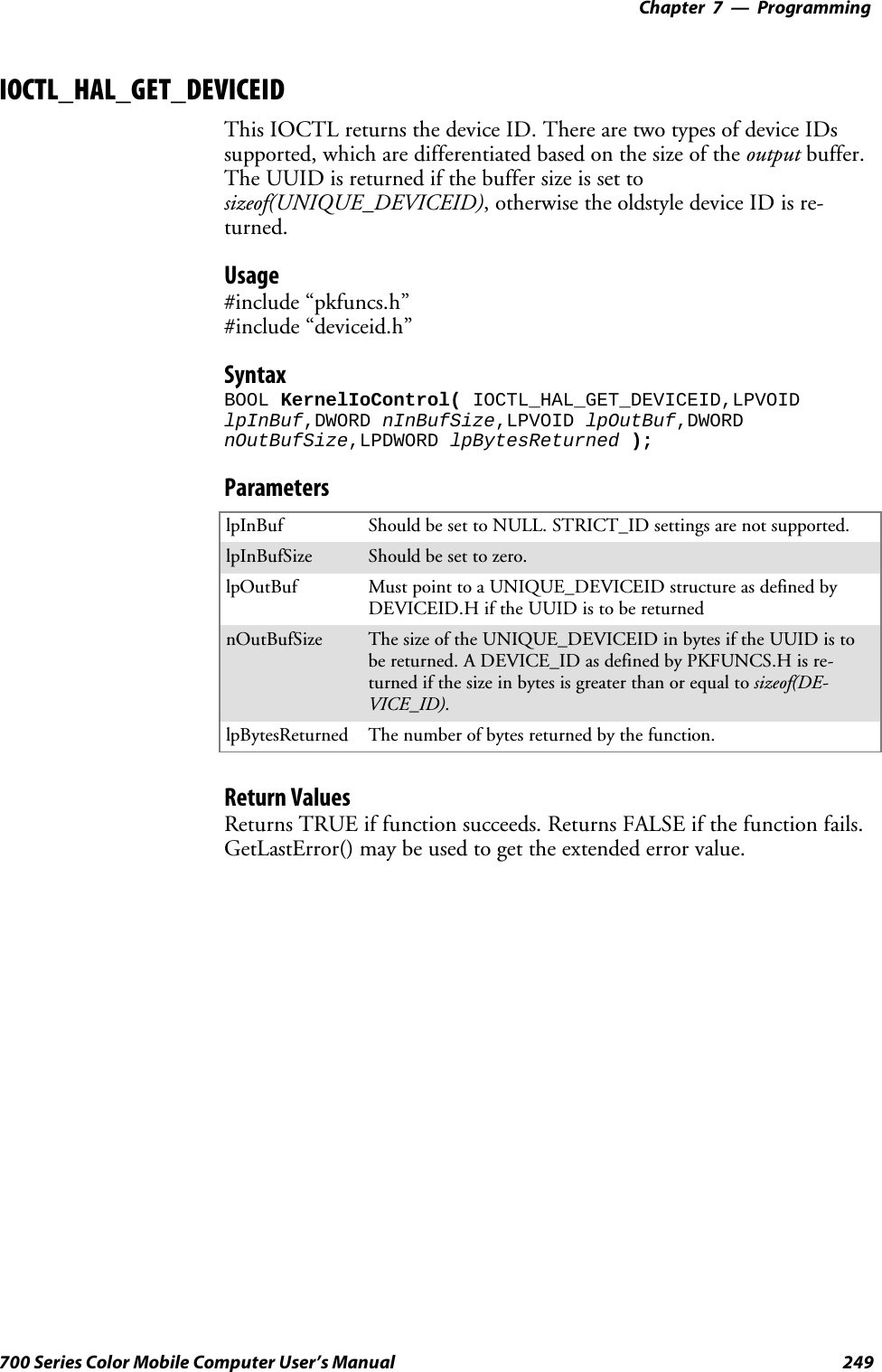
![ProgrammingChapter —7250 700 Series Color Mobile Computer User’s ManualIOCTL_HAL_GET_OAL_VERINFOReturns the HAL version information of the Pocket PC image.Usage#include “oemioctl.h”SyntaxBOOL KernelIoControl( IOCTL_HAL_GET_OAL_VERINFO,LPVOIDlpInBuf,DWORD nInBufSize,LPVOID lpOutBuf,DWORDnOutBufSize,LPDWORD lpBytesReturned );ParameterslpInBuf Should be set to NULL.lpInBufSize Should be set to zero.lpOutBuf Must point to a VERSIONINFO structure as defined byOEMIOCTL.H. The fields should have these values:Scboemverinfo sizeof (tagOemVerInfo);Sverinfover 1Ssig; “ITC\0”Sid; ‘N’Stgtcustomer “”Stgtplat SeaRayStgtplatversion Current build version numberStgtcputype[8]; “Intel\0”Stgtcpu “PXA255\0”;Stgtcoreversion “”Sdate Build timeStime Build datenOutBufSize ThesizeofVERSIONINFOinbytes.lpBytesReturned Returns sizeof(PVERSIONINFO).Return ValuesReturns TRUE if function succeeds. Returns FALSE if the function fails.GetLastError() may be used to get the extended error value.](https://usermanual.wiki/Intermec-Technologies/2610CF.700C-User-Manual-1-of-3/User-Guide-527885-Page-272.png)
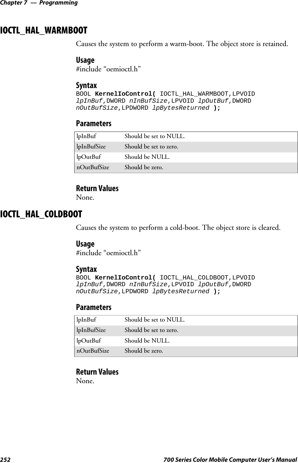
![Programming—Chapter 7251700 Series Color Mobile Computer User’s ManualIOCTL_HAL_GET_BOOTLOADER_VERINFOReturns the HAL version information of the Pocket PC image.Usage#include “oemioctl.h”SyntaxBOOL KernelIoControl( IOCTL_HAL_GET_OAL_VERINFO,LPVOIDlpInBuf, DWORD nInBufSize,LPVOID lpOutBuf,DWORDnOutBufSize,LPDWORD lpBytesReturned );ParameterslpInBuf Should be set to NULL.nInBufSize Should be set to zero.lpOutBuf Must point to a VERSIONINFO structure as defined byOEMIOCTL.H. The fields should have these values:Scboemverinfo Sizeof (tagOemVerInfo);Sverinfover 1Ssig; “ITC\0”Sid; ‘B’Stgtcustomer “”Stgtplat SeaRayStgtplatversion Current build version number of thebootstrap loaderStgtcputype[8]; “Intel\0”;Stgtcpu “PXA255\0”Stgtcoreversion “”Sdate Build timeStime Build datenOutBufSize ThesizeofVERSIONINFOinbytes.lpBytesReturned The number of bytes returned to lpOutBuf.Return ValuesReturns TRUE if function succeeds. Returns FALSE if the function fails.GetLastError() may be used to get the extended error value.](https://usermanual.wiki/Intermec-Technologies/2610CF.700C-User-Manual-1-of-3/User-Guide-527885-Page-273.png)
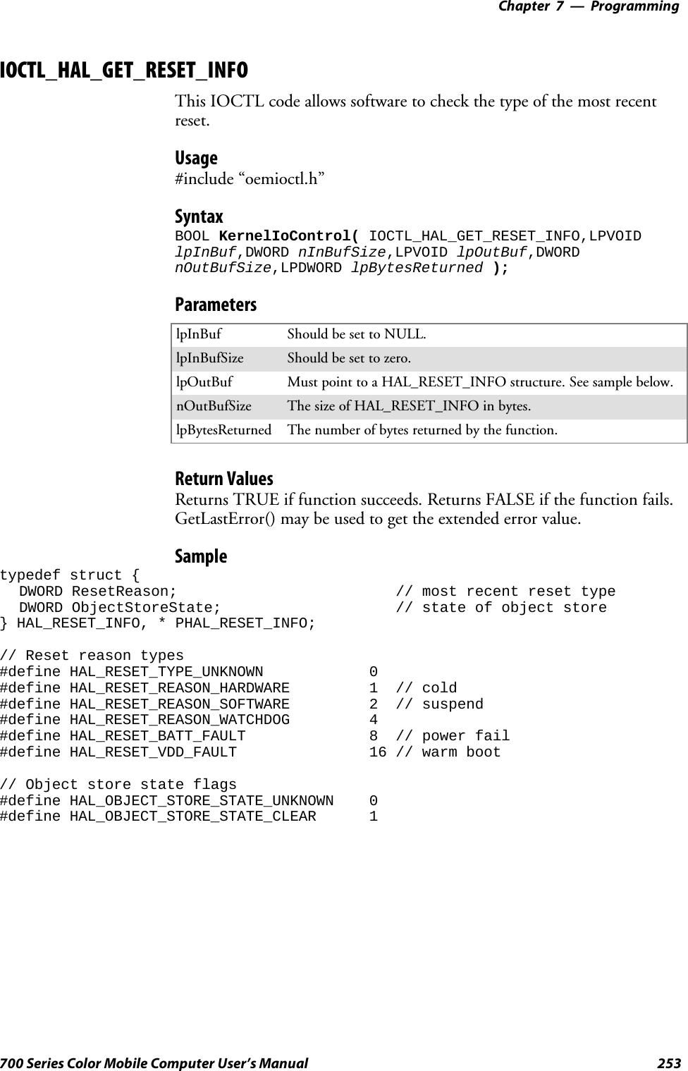
![ProgrammingChapter —7256 700 Series Color Mobile Computer User’s ManualIOCTL_PROCESSOR_INFORMATIONReturns processor information.Usage#include “pkfuncs.h”SyntaxBOOL KernelIoControl( IOCTL_PROCESSOR_INFORMATION,LPVOIDlpInBuf,DWORD nInBufSize,LPVOID lpOutBuf,DWORDnOutBufSize,LPDWORD lpBytesReturned );ParameterslpInBuf Should be set to NULL.nInBufSize Should be set to zero.lpOutBuf Should be a pointer to the PROCESSOR_INFO structure. ThePROCESSOR_INFO structure stores information that describesthe CPU more descriptively.typedef __PROCESSOR_INFO {WORD wVersion; // Set to value 1WCHAR szProcessorCore[40]; // “ARM\0”WORD wCoreRevision; // 4WCHAR szProcessorName[40]; // “PXA255\0”WORD wProcessorRevision; // 0WCAHR szCatalogNumber[100]; // 0WCHAR szVendor[100]; // “Intel Corporation\0”DWORD dwInstructionSet; // 0DWORD dwClockSpeed; // 400}nOutBufSize Should be set to sizeof(PROCESSOR_INFO) in bytes.lpBytesReturned Returns sizeof(PROCESSOR_INFO);Return ValuesReturns TRUE if function succeeds. Returns FALSE if the function fails.GetLastError() may be used to get the extended error value.](https://usermanual.wiki/Intermec-Technologies/2610CF.700C-User-Manual-1-of-3/User-Guide-527885-Page-278.png)
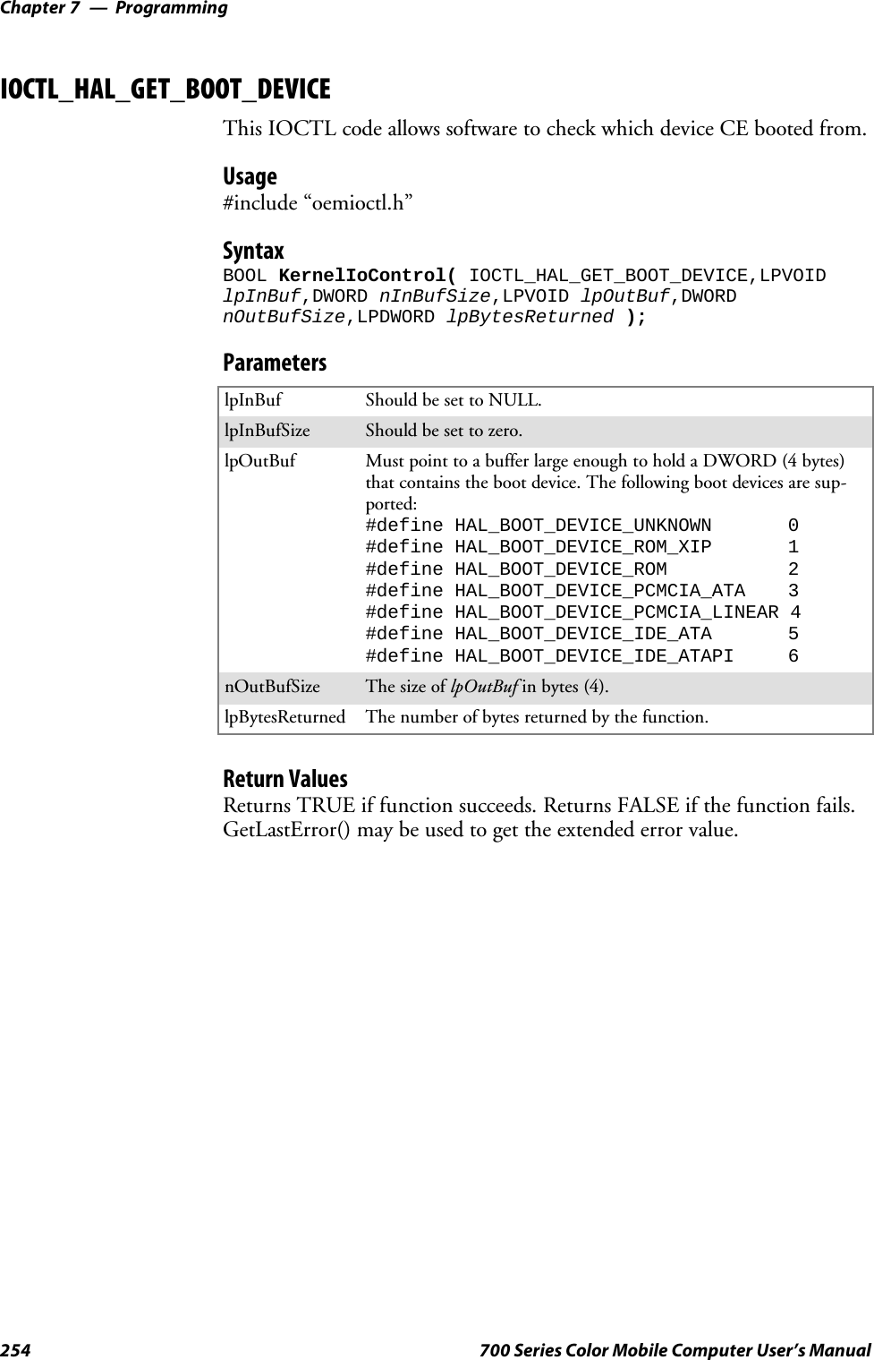
![ProgrammingChapter —7258 700 Series Color Mobile Computer User’s ManualNetwork Selection APIsThe Network Selection APIs change the network adapter configurationprogrammatically. Both drivers support the same IOCTL function num-bers for loading and unloading the drivers.Loading and unloading of the 802.11b or 802.11b/g driver is performedby the FWL1: device in the system by performing DeviceIOControl() callsto the driver.Loading and unloading of the driver for the built-in Ethernet adapter isperformed by the SYI1: device in the system by performingDeviceIOControl() calls to the driver.SFor loading an NDIS driver associated with an adapter, the IOCTL isIOCTL_LOAD_NDIS_MINIPORT.SFor unloading NDIS drivers associated with an adapter the IOCTL isIOCTL_UNLOAD_NDIS_MINIPORT.Example#include <winioctl.h>#include “sysio.h”void DoLoad(int nDevice) {LPTSTR devs[] = { _T(“SYI1:”), _T(“FWL1:”) };HANDLE hLoaderDev;DWORD bytesReturned;hLoaderDev = CreateFile(devs[nDevice], GENERIC_READ|GENERIC_WRITE, 0,NULL, OPEN_EXISTING, 0, NULL);if (hLoaderDev != INVALID_HANDLE_VALUE) {if (!DeviceIoControl( hLoaderDev, IOCTL_LOAD_NDIS_MINIPORT, NULL, -1, NULL, 0,&bytesReturned, NULL)){MessageBox(NULL, TEXT(“SYSIO IoControl Failed”), TEXT(“Networkloader”),MB_ICONHAND);if (hLoaderDev!=INVALID_HANDLE_VALUE) CloseHandle(hLoaderDev);hLoaderDev = INVALID_HANDLE_VALUE; // bad handle}else {CloseHandle(hLoaderDev);}}}void DoUnload(int nDevice) {LPTSTR devs[] = { _T(“SYI1:”), _T(“FWL1:”) };HANDLE hLoaderDev;DWORD bytesReturned;hLoaderDev = CreateFile(devs[nDevice], GENERIC_READ|GENERIC_WRITE, 0,NULL, OPEN_EXISTING, 0, NULL);if (hLoaderDev != INVALID_HANDLE_VALUE) {if (!DeviceIoControl( hLoaderDev, IOCTL_UNLOAD_NDIS_MINIPORT, NULL, -1, NULL, 0,&bytesReturned, NULL)){MessageBox(NULL, TEXT(“SYSIO IoControl Failed”),TEXT(“Networkloader”),MB_ICONHAND);if (hLoaderDev!=INVALID_HANDLE_VALUE) CloseHandle(hLoaderDev);hLoaderDev = INVALID_HANDLE_VALUE; // bad handle}else {CloseHandle(hLoaderDev);}}}](https://usermanual.wiki/Intermec-Technologies/2610CF.700C-User-Manual-1-of-3/User-Guide-527885-Page-280.png)
![ProgrammingChapter —7284 700 Series Color Mobile Computer User’s ManualRemapping the KeypadNote: Use caution when remapping the keypad. Improper remapping mayrender the keypad unusable. Data within the 700 Color Computer couldalso be lost, should any problems occur.Applications have the ability to remap keys on the 700 Color NumericKeypad and 700 Color Alphanumeric Keypad. This will allow applicationsto enable keys that would otherwise not be available, such as the [F1]function key. Also, to disable keys that should not be available, such as thealpha key because no alpha entry is required. Care should be exercisedwhen attempting to remap the keypad because improper remapping maycause the keypad to become unusable. This can be corrected by cold boot-ing the device which will cause the default keymap to be loaded again.Note that remapping the keys in this way affects the key mapping for theentire system, not just for the application that does the remapping.There are three “planes” supported for the 700 Color Numeric Keypadand Alphanumeric Keypad. Keys that are to be used in more than one shiftplane must be described in each plane.Unshifted PlaneThe unshifted plane contains values from the keypad when not pressedwith other keys, such as the following:Press the KeysNumeric Keypad Alphanumeric Keypad To Enter This1M15T59Y9Gold PlaneThe gold plane contains values from the keypad when a key is simulta-neously pressed with the [Gold] bkey on the numeric keypad or the[Gold/White]ckey on the alphanumeric keypad, such as the following:Press the KeysNumeric Keypad Alphanumeric Keypad To Enter This[Gold] b1[Gold/White]ceSend[Gold] b5[Gold/White]cCA3[Gold] b9[Gold/White]cPPgDn](https://usermanual.wiki/Intermec-Technologies/2610CF.700C-User-Manual-1-of-3/User-Guide-527885-Page-306.png)
![Programming—Chapter 7285700 Series Color Mobile Computer User’s ManualAlpha (Blue) PlaneThe alpha plane contains values from the keypad when the keypad hasbeenplacedinalphamodebypressingthebluealphakey,suchasthefol-lowing:Press the KeysNumeric Keypad Alphanumeric Keypad To Enter This[Alpha] F1[Alpha]dgCaps[Alpha] F5[Alpha]dJj[Alpha] F9[Alpha]dWwKey ValuesKey values for each plane are stored in the registry. All units ship with adefault key mapping already loaded in the registry. Applications that wishto change the default mapping need to read the appropriate key from theregistry into an array of Words, modify the values required and then writethe updated values back into the registry. The registry access can be donewith standard Microsoft API calls, such as RegOpenKeyEx(),RegQueryValueEx(), and RegSetValueEx().Numeric KeypadFor the 700 Color Numeric Keypad, the following registry keys containthe plane mappings:STheunshiftedplanemappingcanbefoundintheregistryat:HKEY_LOCAL_MACHINE\HARDWARE\DEVICEMAP\KEYBD\VkeySThe gold plane mapping can be found in the registry at:HKEY_LOCAL_MACHINE\HARDWARE\DEVICEMAP\KEYBD\VkeyGoldSThealphaplanemappingcanbefoundintheregistryat:HKEY_LOCAL_MACHINE\HARDWARE\DEVICEMAP\KEYBD\VkeyAlphaAlphanumeric KeypadFor the 700 Color Alphanumeric Keypad, the following registry keys con-tain the plane mappings:STheunshiftedplanemappingcanbefoundintheregistryat:HKEY_LOCAL_MACHINE\HARDWARE\DEVICEMAP\KEYBD\ALPHA\VkeySThe gold plane mapping can be found in the registry at:HKEY_LOCAL_MACHINE\HARDWARE\DEVICEMAP\KEYBD\ALPHA\VkeyGoldSThealphaplanemappingcanbefoundintheregistryat:HKEY_LOCAL_MACHINE\HARDWARE\DEVICEMAP\KEYBD\ALPHA\VkeyAlpha](https://usermanual.wiki/Intermec-Technologies/2610CF.700C-User-Manual-1-of-3/User-Guide-527885-Page-307.png)
![ProgrammingChapter —7286 700 Series Color Mobile Computer User’s ManualHow Key Values Are Stored in RegistryTo know which fields to update in the registry, you must know what ScanCodes are assigned to each physical key (see the “Keypad Scan Codes andMeanings” tableonthenextpage).TheScanCodeisusedatthelowestlevel of the system to let the keypad driver know which physical key hasbeen pressed. The keypad driver takes that scan code and looks it up in atable (a copy of the one stored in the registry) to determine which valuesto pass on to the operating system.Each registry key is just an array that describes to the keypad driver whatvalue needs to be passed for each physical key. The key values are indexedby the scan code, this is a zero-based index. For example in the unshiftedplane, the [4] key has a scan code of 0x06. This means that the seventhword under the “Vkey” registry key will have the value for the [4] key.Taking a sample of the “Vkey” registry key shows the following values:00,00,0B,05,02,03,C1,07,04,03,BE,00,34,00,00,00,. . .Thevalueis34,00.Thevaluesareinreversebyteorderbecausethatistheway the processor handles data. When writing an application, nothingneeds to be done to swap the bytes, as this will happen automatically whenthe data is read into a byte value. This is something you just need to beaware of when looking at the registry. Knowing this, we can see that thevalue that the keypad driver will pass to the system is a hex 34. Lookingthat up on an UNICODE character chart, we see that it maps to a “4”. Ifyou wanted the key, labeled “4”, to output the letter “A” instead, youwould need to change the seventh word to “41” (the hexadecimal repre-sentation of “A” from the UNICODE chart), then put the key back intothe registry.Note: Do not remap scan codes 0x01, 0x41, 0x42, 0x43, 0x44. Remap-pingthesescancodescouldrenderyour700ColorComputerunusableuntil a cold-boot is performed.If you wish to disable a certain key, remap its scan code to 0x00.Change NotificationJust changing the registry keys will not immediately change the keymappings. To notify the keypad driver that the registry has been updated,signal the “ITC_KEYBOARD_CHANGE” named event using theCreateEvent() API.Advanced Keypad RemappingIt is also possible to map multiple key presses to one button and to mapnamed system events to a button. The multiple key press option could beuseful to cut down on the number of keys needed to press in a given situa-tion or to remap which key behaves like the action key. Mapping events toa button could be useful to change which buttons will fire the scanner,control volume, and allow for suspending and resuming the device. If youneed help performing one of these advanced topics please contact IntermecTechnical Support.](https://usermanual.wiki/Intermec-Technologies/2610CF.700C-User-Manual-1-of-3/User-Guide-527885-Page-308.png)
![Programming—Chapter 7287700 Series Color Mobile Computer User’s ManualScan CodesAt the lowest driver level, the 700 Color Numeric Keypad and the 700ColorAlphanumericKeypadidentifieskeysasscancodes.Thesescancodes are sent via the keypad microcontroller, and cannot be changedwithout modifying the keypad firmware.Numeric KeypadThe following scan codes pertain to the 700 Color Numeric keypad:Numeric Keypad Scan Codes and MeaningsPressthisKey Meaning ScanCodeReserved 0x00II/O button 0x01Scanner Handle Trigger 0x02Scanner Left 0x03Scanner Right 0x0444/GHI/A2 0x06None 0x07LLeft arrow/Back Tab 0x08None 0x09KBkSp// (forward slash) 0x0Ab[Gold] key 0x0BNone 0x0CEEsc/– (minus sign) 0x0DDDown arrow/Volume decrease 0x0E11/Caps/Send 0x0F77/PQRS/PgUp 0x10F[Alpha] key 0x11None 0x12UUp arrow/Volume increase 0x13RRight arrow/Tab 0x1422/ABC/End 0x1588/TUV/* (asterisk) 0x1600/Win 0x1755/JKL/A3 0x18None 0x19AAction/+ (plus symbol) 0x1A33/DEF/backlight 0x1B99/WXYZ/PgDn 0x1C](https://usermanual.wiki/Intermec-Technologies/2610CF.700C-User-Manual-1-of-3/User-Guide-527885-Page-309.png)
![ProgrammingChapter —7290 700 Series Color Mobile Computer User’s ManualSample View of Registry KeysThe following is a sample view of the current default key mapping for the700 Color Numeric Keypad. See the registry on your device for the latestkey mappings.[HKEY_LOCAL_MACHINE\HARDWARE\DEVICEMAP\KEYBD]”ResumeMask”=dword:7”Vkey”=hex: 00,00,0B,05,02,03,C1,07,04,03,BE,00,34,00,00,00,\25,00,00,00,08,00,03,02,00,00,1B,00,28,00,31,00,\37,00,01,02,00,00,26,00,27,00,32,00,38,00,30,00,\35,00,00,00,01,03,33,00,39,00,0D,00,36,00,00,00,\00,00,00,00,00,00,00,00,00,00,00,00,00,00,00,00,\00,00,00,00,00,00,00,00,00,00,00,00,00,00,00,00,\00,00,00,00,00,00,00,00,00,00,00,00,00,00,00,00,\00,00,00,00,00,00,00,00,00,00,00,00,00,00,00,00,\00,00,07,05,01,05,03,05,02,05”VkeyGold”=hex: 00,00,0B,05,02,03,C1,07,04,03,BE,00,34,00,00,00,\09,01,00,00,BF,00,03,02,00,00,BD,00,75,00,72,00,\21,00,01,02,00,00,76,00,09,00,73,00,38,01,5B,00,\35,00,00,00,BB,01,09,05,22,00,32,01,36,00,00,00,\00,00,00,00,00,00,00,00,00,00,00,00,00,00,00,00,\00,00,00,00,00,00,00,00,00,00,00,00,00,00,00,00,\00,00,00,00,00,00,00,00,00,00,00,00,00,00,00,00,\00,00,00,00,00,00,00,00,00,00,00,00,00,00,00,00,\00,00,07,05,01,05,03,05,02,05”VkeyAlpha”=hex: 00,00,0B,05,02,03,C1,07,04,03,BE,00,47,00,00,00,\25,00,00,00,08,00,03,02,00,00,1B,00,28,00,02,02,\50,00,01,02,00,00,26,00,27,00,41,00,54,00,20,00,\4A,00,00,00,01,03,44,00,57,00,0D,00,4D,00,00,00,\00,00,00,00,00,00,00,00,00,00,00,00,00,00,00,00,\00,00,00,00,00,00,00,00,00,00,00,00,00,00,00,00,\00,00,00,00,00,00,00,00,00,00,00,00,00,00,00,00,\00,00,00,00,00,00,00,00,00,00,00,00,00,00,00,00,\00,00,07,05,01,05,03,05,02,05](https://usermanual.wiki/Intermec-Technologies/2610CF.700C-User-Manual-1-of-3/User-Guide-527885-Page-312.png)

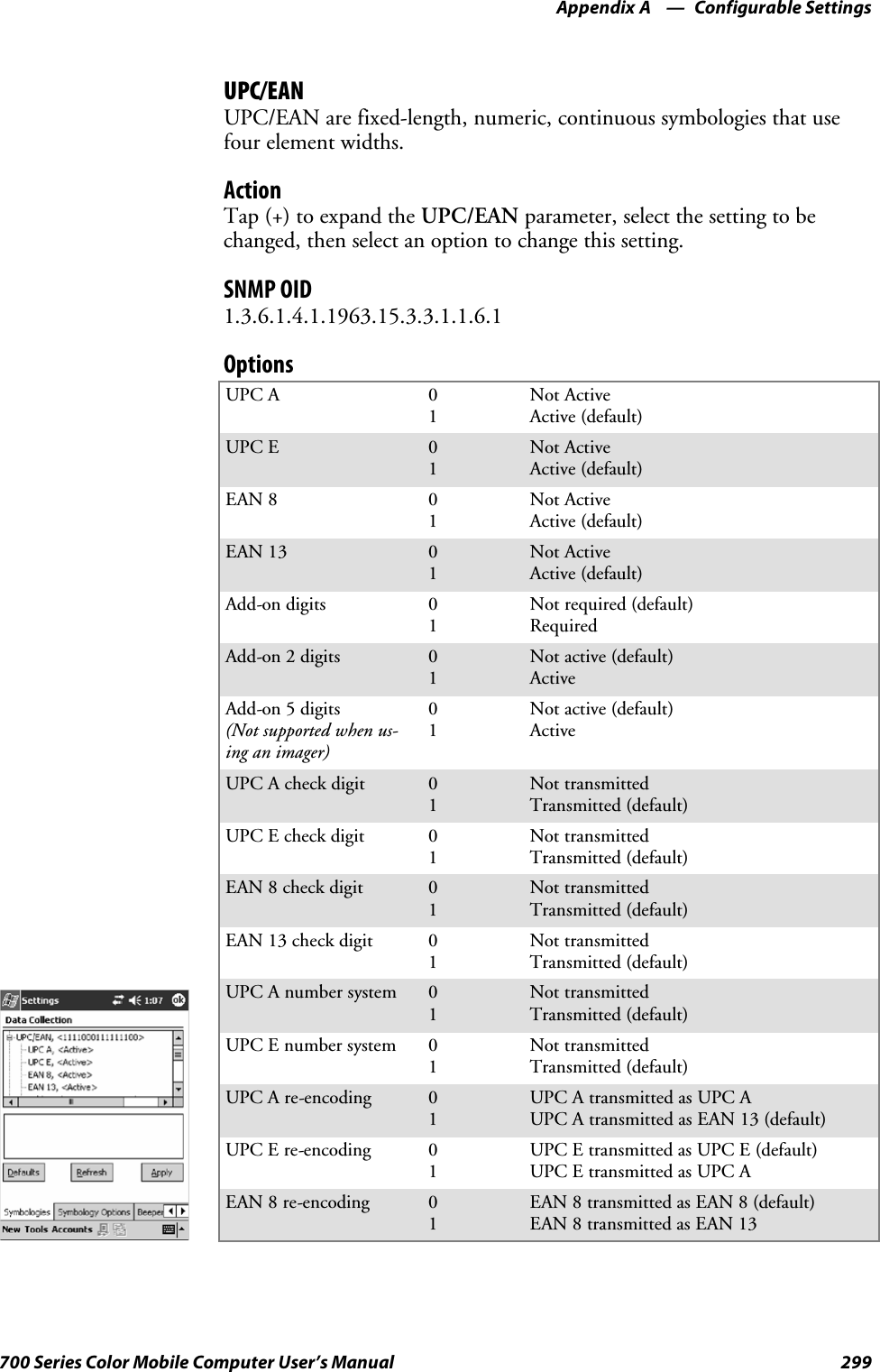
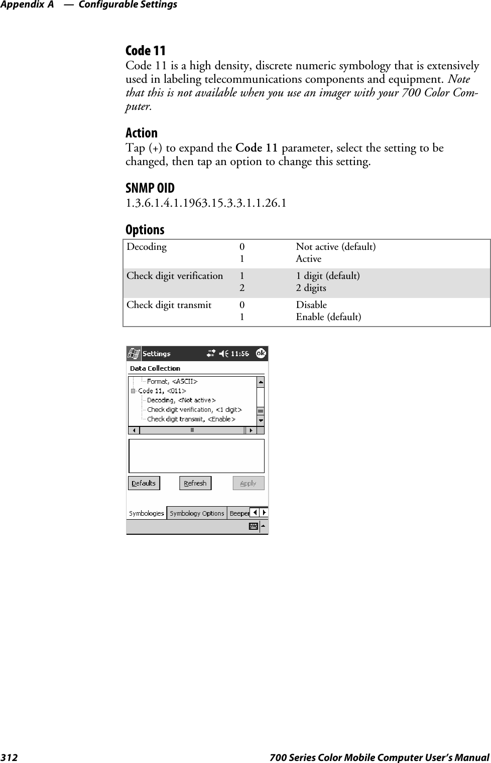
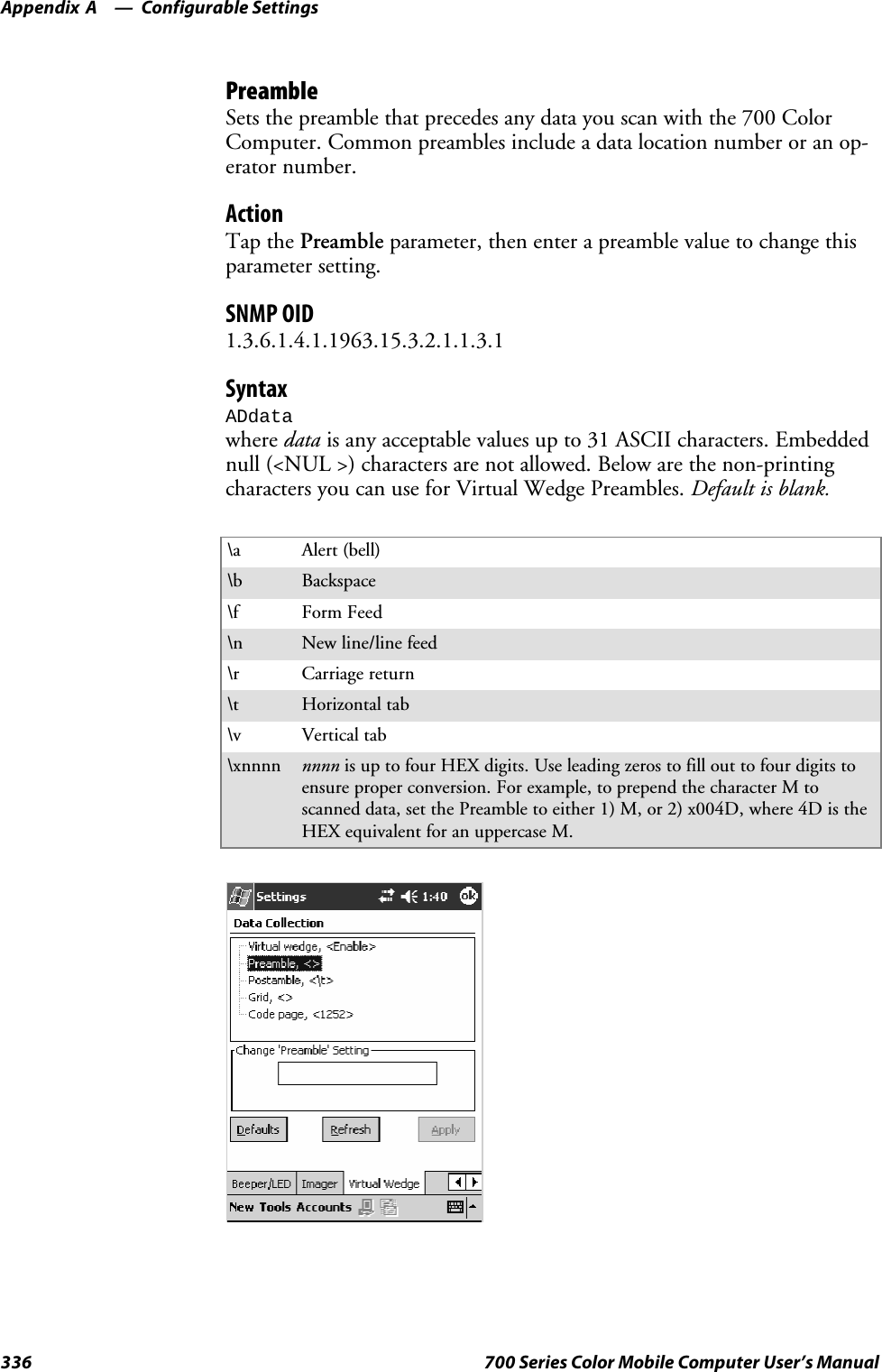
![Configurable SettingsAppendix —A302 700 Series Color Mobile Computer User’s ManualCode 128 OptionsSet the following for the Code 128 parameter. Note that the EAN 128 ]C1and CIP 128 French Pharmaceutical options are not available when you usean imager with your 700 Color Computer.ActionTap (+) to expand the Code 128 Options parameter, select a setting, thenselect an option to change this setting.SNMP OIDNone.OptionsEAN 128 ]C1 Identifier(Not supported when using animager)01Remove (default)IncludeCIP 128 French Pharmaceutical(Not supported when using animager)01Not active (default)ActiveBar code length 01Any length (default)Minimum lengthMinimum length 001–254 Minimum length 1–254 (default is 6)This illustration is from a 700 Color Computer using a laser scanner.](https://usermanual.wiki/Intermec-Technologies/2610CF.700C-User-Manual-1-of-3/User-Guide-527885-Page-324.png)
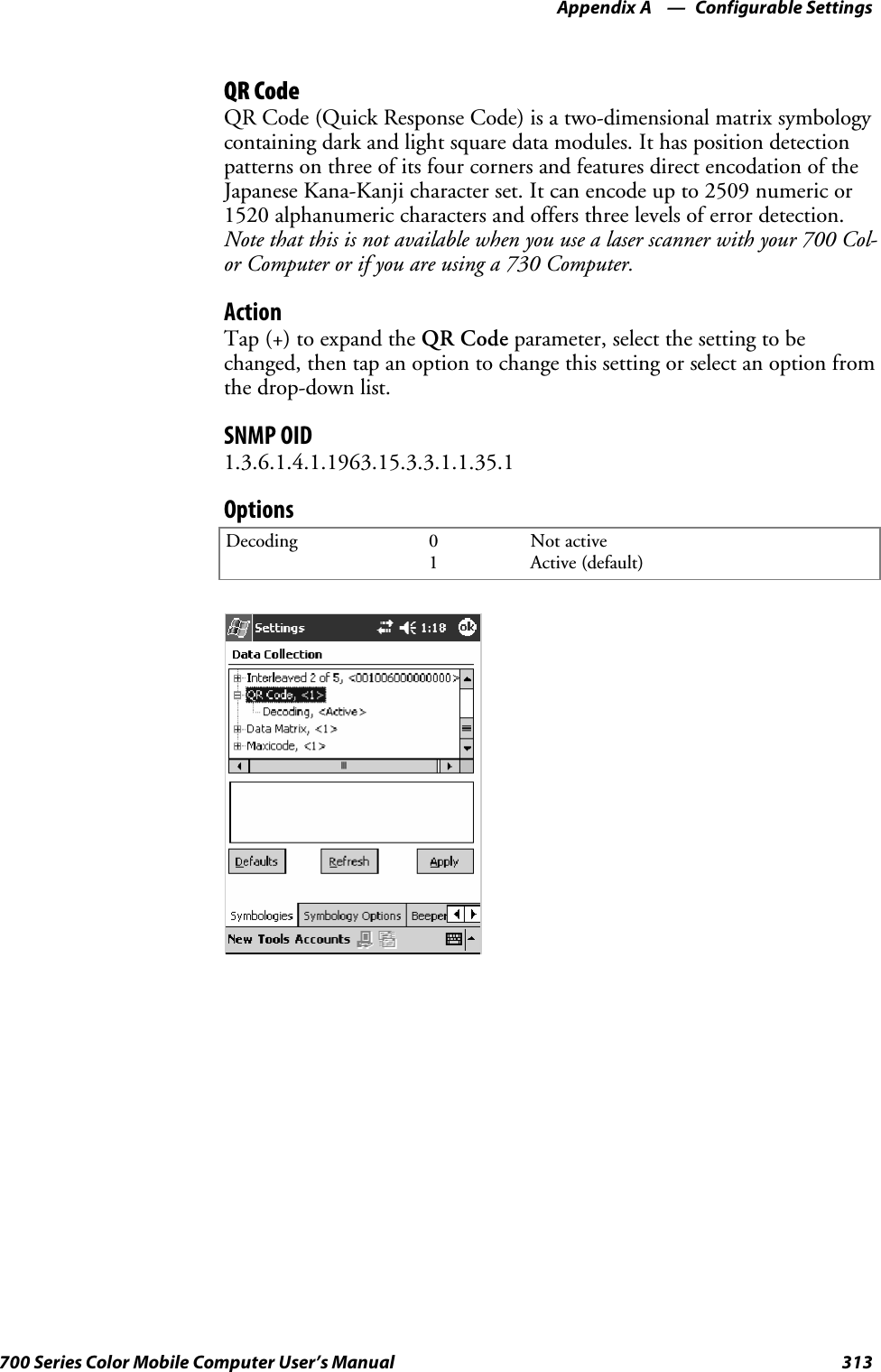
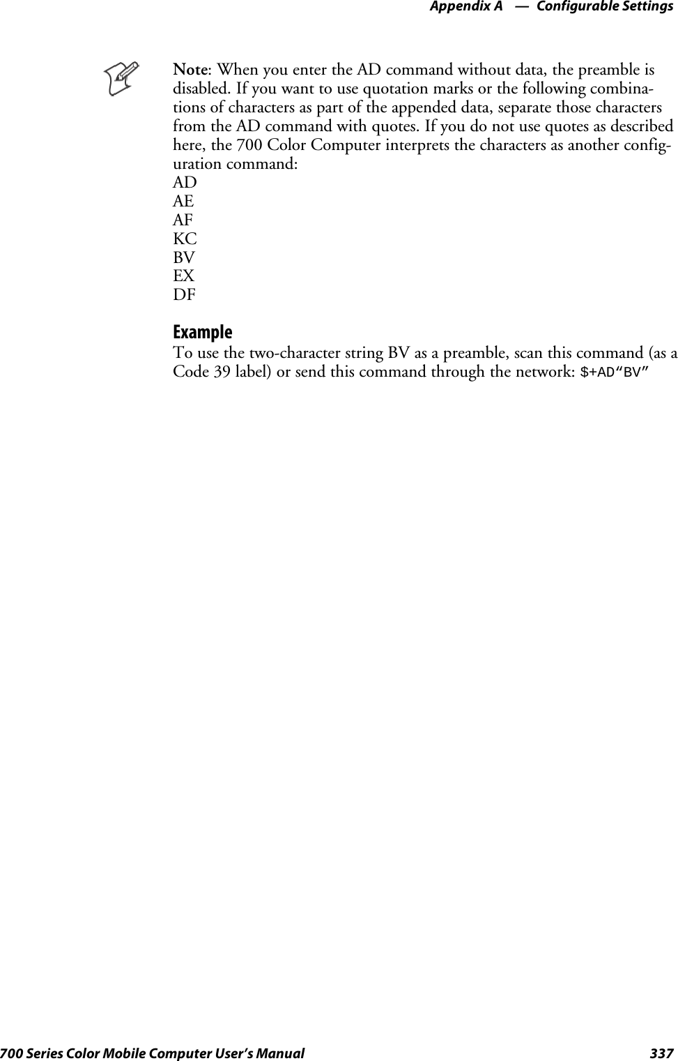
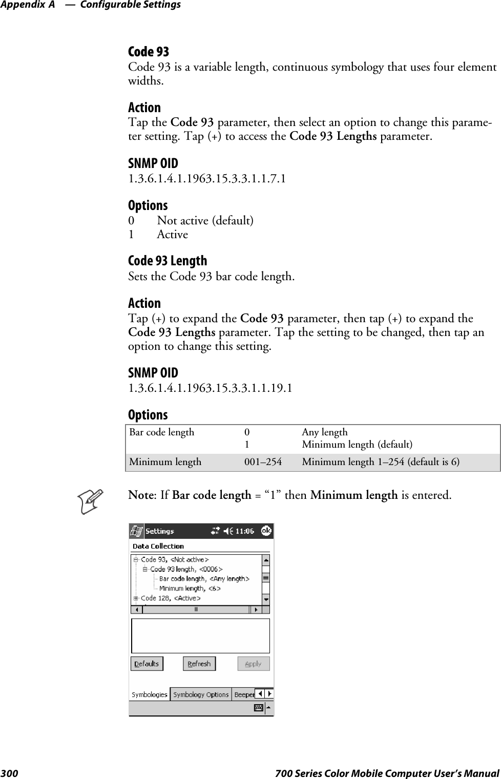
![Configurable SettingsAppendix —A360 700 Series Color Mobile Computer User’s ManualWakeup MaskFrom the 700 Color Computer, tap Start >Settings >theSystem tab >Utilities >theWakeup Mask tab to access the Wakeup Mask control pan-el applet.This applet programs three scanner buttons and the A1 and A2 applicationkeys to be “wakeup” or resume keys. That is, to prompt the 700 ColorComputer to “wake up” or resume activity after going to “sleep” as a resultof being inactive after a length of time. This information will remain be-tween warm and cold boots.Check the appropriate box, then tap ok to apply your settings.Based on your setting, do the following to “wake up” the 700 Color Com-puter.If you select:Then do this onNumeric KeyboardThen do this onAlphanumeric KeyboardMiddle Scanner Button SqueezethebuttonontheScanHandle SqueezethebuttonontheScanHandleLeft Scanner Button Squeeze the left scanner button Squeeze the left scanner buttonRight Scanner Button Squeeze the right scanner button Squeeze the right scanner buttonGOLD+A1(Application1) Press [Gold]baPress [Gold/White]cAGOLD+A2(Application2) Press [Gold]b4Press [Gold/White]cB](https://usermanual.wiki/Intermec-Technologies/2610CF.700C-User-Manual-1-of-3/User-Guide-527885-Page-382.png)
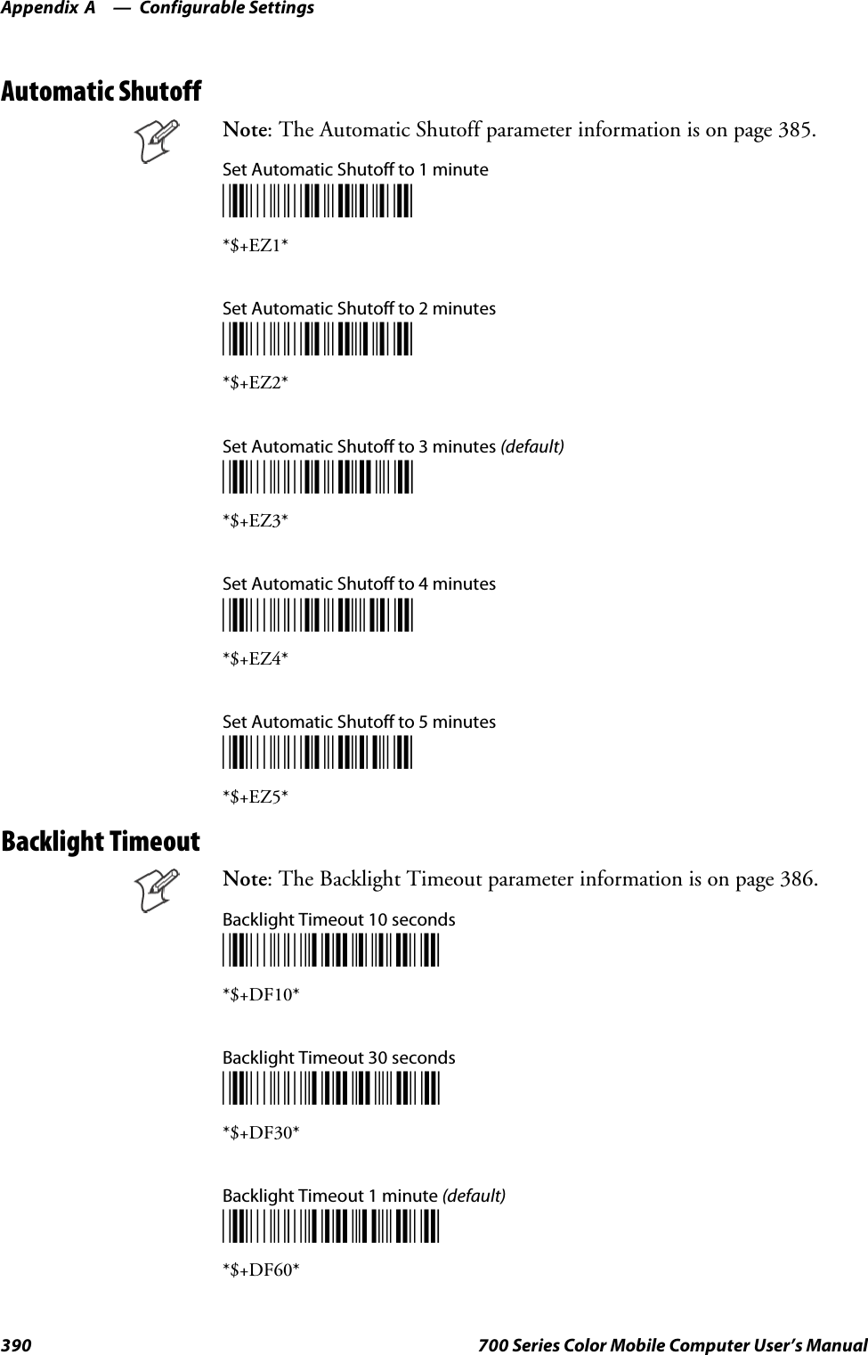
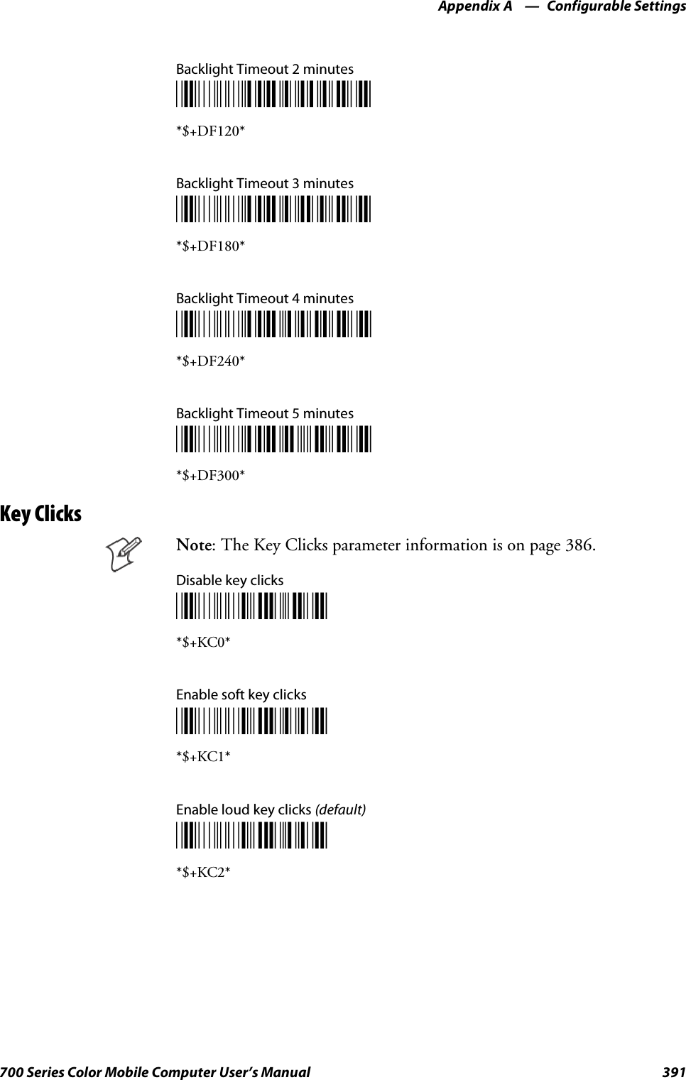
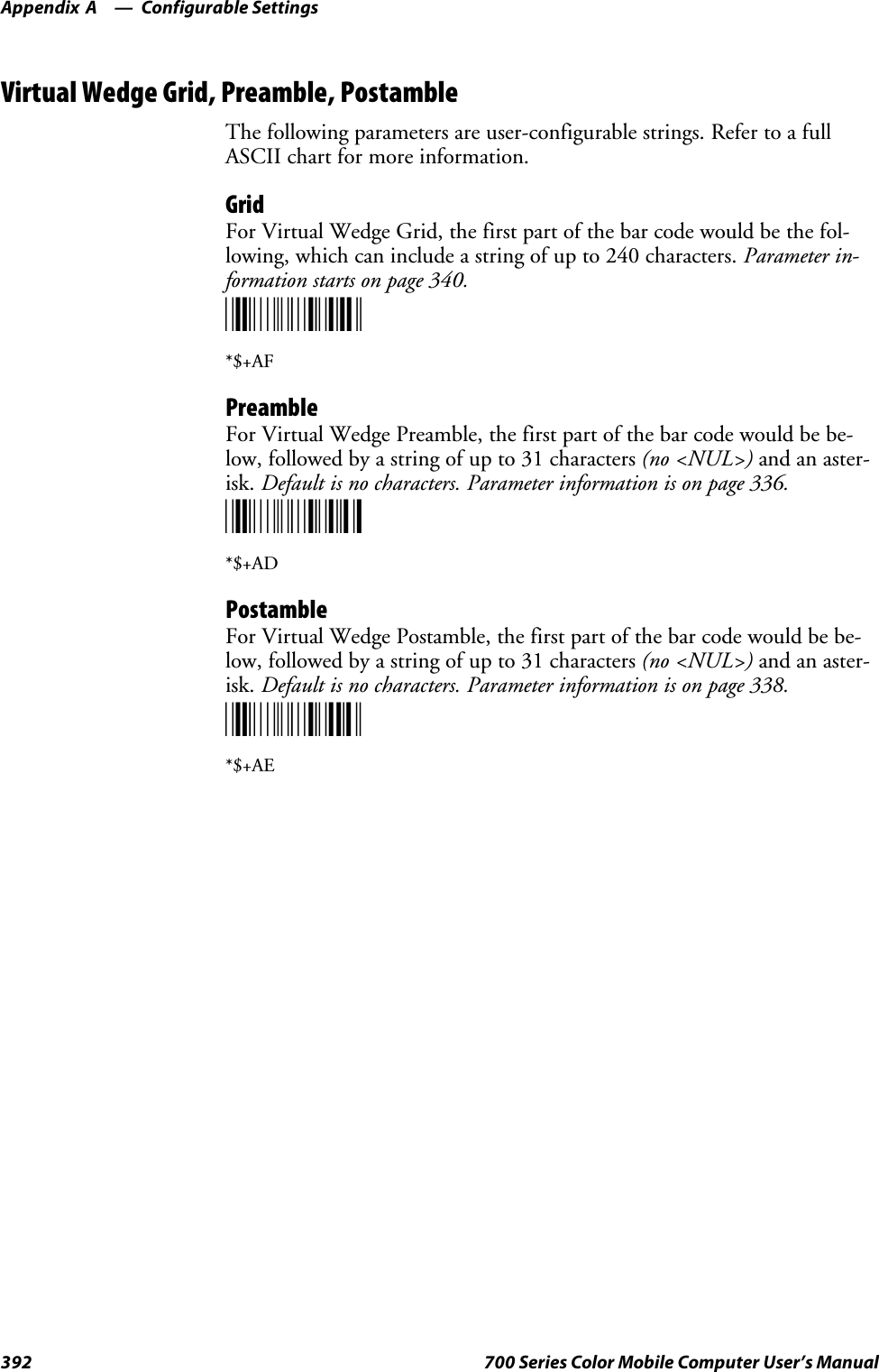
![Configurable SettingsAppendix —A387700 Series Color Mobile Computer User’s ManualUsing Reader CommandsAfter the 700 Color Computer is connected to your network, you cansend the 700 Color Computer a reader command from an application toperform a task, such as changing the time and date. Some reader com-mands temporarily override the configuration settings and some changethe configuration settings.Change ConfigurationThe Change Configuration command must precede any configurationcommand. If you enter a valid string, the 700 Color Computer configura-tion is modified and the computer emits a high beep. To send the ChangeConfiguration command through the network, use the$+ [command]syntax where command is the two-letter command syntax for the configu-ration command followed by the value to be set for that command.You can also make changes to several different commands by using the$+ [command]...[command n]syntax. There are seven configurationcommand settings that can be changed in this way. See each command forinformation on respective acceptable “data” values.Command SyntaxAudio Volume BVdataAutomatic Shutoff EZdataBacklight Timeout DFdataKey Clicks KCdataVirtual Wedge Grid AFdataVirtual Wedge Postamble AEdataVirtual Wedge Preamble ADdataNote: See pages 336 and 338 for more information about the VirtualWedge Postamble and Virtual Wedge Preamble commands.Example 1To change the Beep Volume to Off, you can send this string to the 700ColorComputerthroughthenetwork:$+BV0where:$+ Indicates Change Configuration.BV Specifies the Audio Volume parameter.0Specifies a value of Off.Example 2To change the Beep Volume to Very Quiet and the Virtual Wedge Gridto 123:$+BV1AF123where:$+ Indicates Change ConfigurationBV1 Specifies Audio Volume, set to Very Quiet (1)AF123 Specifies Virtual Wedge Grid, set to a value of 123.](https://usermanual.wiki/Intermec-Technologies/2610CF.700C-User-Manual-1-of-3/User-Guide-527885-Page-409.png)

![Bar Code SymbologiesAppendix —B396 700 Series Color Mobile Computer User’s ManualCode 128Code 128 (C128) is one of the newest symbologies used by the retail andmanufacturing industries. It responds to the need for a compact alphanu-meric bar code symbol that could encode complex product identification.The fundamental requirement called for a symbology capable of beingprinted by existing data processing printers (primarily dot-matrix printers)that produce daily, work-in-progress, job, and product traceability docu-ments. The ability to print identification messages between 10 and 32characters long, on existing forms and labels deemed an important require-ment.Code 128 uniquely addresses this need as the most compact, complete,alphanumeric symbology available.Additionally, the Code 128 design with geometric features, improves scan-ner read performance, does self-checking, and provides data message man-agement function codes.Code 128 encodes the complete set of 128 ASCII characters without ad-ding extra symbol elements. Code 128 contains a variable-length symbolo-gy and the ability to link one message to another for composite messagetransmission. Code 128, being a double-density field, provides two numer-ic values in a single character.Code 128 follows the general bar code format of start zone, data, checkdigit, stop code, and quiet zone. An absolute minimum bar or space di-mension of nine mils (0.010 inch minimum nominal ±0.001 inch toler-ance) must be maintained.Characters in Code 128 consist of three bars and three spaces so that thetotal character set includes three different start characters and a stop char-acter.UCC/EAN-128 Shipping Container Labeling is a versatile tool that canease movement of products and information. The Shipping Container La-beling bar code can take any form and usually has meaning only within thecompany or facility where applied.Because this random data can get mistaken later for an industry standardcode format, the UCC and EAN chose a symbology uniquely identifiedfrom these other bar codes. This standard is for maximum flexibility, tohandle the diversity of distribution in global markets by cost efficiency.The UCC/EAN-128 Container Labeling specification calls for a FUNC1to immediately follow the bar code’s start character. FUNC1 also followsany variable-length application field. The specification also calls for thecomputer to send “]C1” for the first FUNC1. The specification requiresthat the computer send a “<GS>” (hex 1D) for subsequent FUNC1 codesin the bar code.Because “<GS>” is not compatible with computer emulation data streams,the Uniform Code Council has been asked to change the specification.This change is made to send the same three character sequence “]C1” toidentify the embedded FUNC1 codes.](https://usermanual.wiki/Intermec-Technologies/2610CF.700C-User-Manual-1-of-3/User-Guide-527885-Page-418.png)

![Index404 700 Series Color Mobile Computer User’s ManualClasses and FunctionsAadd_registry_section, [AddReg]flags, 224registry_root_string, 224value_name, 224AddReg, [DefaultInstall], 220[AddReg], add_registry_sectionflags, 224registry_root_string, 224value_name, 224AddWep(), 270ANT_DIVERSITY, GetDiversity(), 263ANT_PRIMARY, GetDiversity(), 263ANT_SECONDARY, GetDiversity(), 263AppName, [CEStrings], 217Asset management, DeviceURL parameter, 235BBasic connect/disconnect functions, 260BlockSize, FTP Server, 235BuildMax, [CEDevice], 218BuildMin, [CEDevice], 218C[CEDevice]BuildMax, 218BuildMin, 218ProcessorType, 218UnsupportedPlatforms, 218VersionMax, 218VersionMin, 218CESelfRegister, [DefaultInstall], 220CESetupDLL, [DefaultInstall], 220CEShortcuts, [DefaultInstall], 220[CEShortcuts], shortcut_list_sectionshortcut_filename, 225shortcut_type_flag, 225target_file/path, 225target_file_path, 225CESignature[SourceDiskNames], 220[Version], 216[CEStrings]AppName, 217InstallDir, 217ClassID field valuesVN_CLASS_ASIC, 244VN_CLASS_BOOTSTRAP, 244VN_CLASS_KBD, 244CloseHandle()DTR printing, 196, 197IrDA printing, 190NPCP printing, 191, 192Cold boot, IOCTL_HAL_COLDBOOT, 252ConfigureProfile(), 275Copyfiles, [DefaultInstall], 220[CopyFiles], file_list_sectiondestination_filename, 223flags, 223source_filename, 223CreateEvent(), 286CreateFile()DTR printing, 196, 197IrDA printing, 190NPCP printing, 191, 192D[DefaultInstall]AddReg, 220CESelfRegister, 220CESetupDLL, 220CEShortcuts, 220Copyfiles, 220Deprecated functions, 280DeregisterDevice(), 191DTR printing, 196[DestinationDirs], file_list_section, 222DeviceIOControl(), 258DTR printing, 196NPCP printing, 191DeviceIoControl(), NPCP printing, 192, 193DeviceName,FTPServer,235DeviceURL, FTP Server, 235disk_ordinal, [SourceDiskNames], 220DllRegisterServer, 220DllUnregisterServer, 220EEnableSuppLogging(), 279EnableWep(), 270EnableZeroConfig(), 276EncryptionStatus(), 271EncryptWepKeyForRegistry(Deprecated), 280ERROR_INSUFFICIENT_BUFFERIOCTL_HAL_ITC_READ_PARM, 243IOCTL_HAL_ITC_WRITE_SYSPARM, 247ERROR_INVALID_PARAMETERIOCTL_HAL_ITC_READ_PARM, 243IOCTL_HAL_ITC_WRITE_SYSPARM, 247FFile Transfer Protocol. See FTPfile_list_section[CopyFiles]destination_filename, 223flags, 223source_filename, 223[DestinationDirs], 222filename, [SourceDiskFiles], 221](https://usermanual.wiki/Intermec-Technologies/2610CF.700C-User-Manual-1-of-3/User-Guide-527885-Page-426.png)
![Index406 700 Series Color Mobile Computer User’s ManualITC_NVPARM_WAN_RI, 244IOCTL_HAL_ITC_WRITE_SYSPARMITC_ DOCK_SWITCH, 248ITC_ WAKEUP_MASK, 248ITC_AMBIENT_FRONTLIGHT, 248ITC_AMBIENT_KEYBOARD, 248ITC_REGISTRY_SAVE_ENABLE, 248IDNADeviceName, 235DeviceURL, 235IDNATarget, FTP Server, 236InstallDir, [CEStrings], 217Intermec Device Network Announcement. See IDNAIOCTL_GET_CPU_ID, 257IOCTL_HAL_COLDBOOT, 252, 283IOCTL_HAL_GET_BOOT_DEVICE, 254IOCTL_HAL_GET_BOOTLOADER_VERINFO, 251IOCTL_HAL_GET_DEVICE_INFO, 242IOCTL_HAL_GET_DEVICEID, 249IOCTL_HAL_GET_OAL_VERINFO, 250IOCTL_HAL_GET_RESET_INFO, 253IOCTL_HAL_ITC_READ_PARM, 243IOCTL_HAL_ITC_WRITE_SYSPARM, 247IOCTL_HAL_REBOOT, 255, 283IOCTL_HAL_WARMBOOT, 252, 283IOCTL_LOAD_NDIS_MINIPORT, 258IOCTL_PROCESSOR_INFORMATION, 256IOCTL_UNLOAD_NDIS_MINIPORT, 258isDHCPEnabled(), 278isOrinoco(), 276isSupplicantRunning(), 277isZeroConfigEnabled(), 276ITC_ DOCK_SWITCH, 248ITC_ WAKEUP_MASK, 248ITC_AMBIENT_FRONTLIGHT, 248ITC_AMBIENT_KEYBOARD, 248ITC_DEVID_80211RADIO_INTEL_2011B, 245ITC_DEVID_80211RADIO_MAX valuesITC_DEVID_80211RADIO_INTEL_2011B, 245ITC_DEVID_80211RADIO_NONE, 245ITC_DEVID_80211RADIO_NONE, 245ITC_DEVID_INTERMEC_EVIO, 245ITC_DEVID_INTERMEC2D_IMAGER, 245ITC_DEVID_OEM2D_IMAGER, 245ITC_DEVID_SCANHW_MAX valuesITC_DEVID_INTERMEC_EVIO, 245ITC_DEVID_INTERMEC2D_IMAGER, 245ITC_DEVID_OEM2D_IMAGER, 245ITC_DEVID_SCANHW_NONE, 245ITC_DEVID_SE900_LASER, 245ITC_DEVID_SE900HS_LASER, 245ITC_DEVID_SCANHW_NONE, 245ITC_DEVID_SE900_LASER, 245ITC_DEVID_SE900HS_LASER, 245ITC_DEVID_WANRADIO_NONE, 245ITC_DEVID_WANRADIO_SIEMENS_MC45, 245ITC_DEVID_WANRADIO_SIEMENS_MC46, 245ITC_DEVID_WANRADIO_SIERRA_SB555, 245ITC_DEVID_WANRADIO_XIRCOM_GEM3503, 245ITC_IFTP_STOP, 240ITC_NVPARM_80211_INSTALLED, 245ITC_NVPARM_80211_RADIOTYPE, 245ITC_NVPARM_ANTENNA_DIVERSITY, 244ITC_NVPARM_BLUETOOTH_INSTALLED, 246ITC_NVPARM_CONTRAST, 244ITC_NVPARM_DISPLAY_TYPE, 244ITC_NVPARM_ECN, 244ITC_NVPARM_EDBG_SUBNET, 244ITC_NVPARM_EDG_IP, 244ITC_NVPARM_ETHERNET_ID, 243ITC_NVPARM_INTERMEC_DATACOLLEC-TION_HW, 245ITC_NVPARM_INTERMEC_DATACOLLEC-TION_SW, 245ITC_NVPARM_INTERMEC_SOFTWARE_CON-TENT, 244ITC_NVPARM_LAN9000_INSTALLED, 246ITC_NVPARM_MANF_DATE, 243ITC_NVPARM_MCODE, 244ITC_NVPARM_RTC_RESTORE, 245ITC_NVPARM_SERIAL_NUM, 243ITC_NVPARM_SERIAL2_INSTALLED, 246ITC_NVPARM_SERVICE_DATE, 243ITC_NVPARM_SIM_PROTECT_HW_INSTALLED,246ITC_NVPARM_SIM_PROTECT_SW_INSTALLED,246ITC_NVPARM_VERSION_NUMBER, 244ITC_NVPARM_VIBRATE_INSTALLED, 246ITC_NVPARM_WAN_FREQUENCY, 245ITC_NVPARM_WAN_INSTALLED, 245ITC_NVPARM_WAN_RADIOTYPE, 245ITC_NVPARM_WAN_RI, 244ITC_REGISTRY_SAVE_ENABLE, 248KKernelIoControlIOCTL_GET_CPU_ID, 257IOCTL_HAL_COLDBOOT, 252, 283IOCTL_HAL_GET_BOOT_DEVICE, 254IOCTL_HAL_GET_BOOTLOADER_VERINFO,251IOCTL_HAL_GET_DEVICE_INFO, 242IOCTL_HAL_GET_DEVICEID, 249IOCTL_HAL_GET_OAL_VERINFO, 250IOCTL_HAL_GET_RESET_INFO, 253IOCTL_HAL_ITC_READ_PARM, 243IOCTL_HAL_ITC_WRITE_SYSPARM, 247IOCTL_HAL_REBOOT, 255, 283IOCTL_HAL_WARMBOOT, 252, 283IOCTL_PROCESSOR_INFORMATION, 256KernelIoControl(), 242](https://usermanual.wiki/Intermec-Technologies/2610CF.700C-User-Manual-1-of-3/User-Guide-527885-Page-428.png)
![Index408 700 Series Color Mobile Computer User’s ManualNDIS_POWER_LEVEL_UNKNOWN, GetTXPower(),267NDIS_RADIO_ASSOCIATED, GetAssocationStatus(),261NDIS_RADIO_AUTH_MODE_AUTOGetAuthenticationMode(), 262SetAuthenticationMode(), 272NDIS_RADIO_AUTH_MODE_ERRORGetAuthenticationMode(), 262SetAuthenticationMode(), 272NDIS_RADIO_AUTH_MODE_OPENGetAuthenticationMode(), 262SetAuthenticationMode(), 272NDIS_RADIO_AUTH_MODE_SHAREDGetAuthenticationMode(), 262SetAuthenticationMode(), 272NDIS_RADIO_AUTH_MODE_WPAGetAuthenticationMode(), 262SetAuthenticationMode(), 272NDIS_RADIO_AUTH_MODE_WPA_NONEGetAuthenticationMode(), 262SetAuthenticationMode(), 272NDIS_RADIO_AUTH_MODE_WPA_PSKGetAuthenticationMode(), 262SetAuthenticationMode(), 272NDIS_RADIO_POWER_AUTOGetPowerMode(), 266SetPowerMode(), 273NDIS_RADIO_POWER_MODE_CAMGetPowerMode(), 266SetPowerMode(), 273NDIS_RADIO_POWER_MODE_FAST_PSPGetPowerMode(), 266SetPowerMode(), 273NDIS_RADIO_POWER_MODE_PSPGetPowerMode(), 266SetPowerMode(), 273NDIS_RADIO_POWER_UNKNOWNGetPowerMode(), 266SetPowerMode(), 273NDIS_RADIO_SCANNING, GetAssociationStatus(), 261nInBufSizeIOCTL_HAL_GET_BOOTLOADER_VERINFO,251IOCTL_HAL_ITC_READ_PARM, 243IOCTL_HAL_ITC_WRITE_SYSPARM, 247IOCTL_PROCESSOR_INFORMATION, 256nInfoId, NLEDGetDeviceInfo, 282NLED_COUNT_INFO, NLEDGetDeviceInfo, 282NLED_SETTINGS_INFO_ID, NLEDGetDeviceInfo,282NLED_SUPPORTS_INFO_ID, NLEDGetDeviceInfo,282NLEDGetDeviceInfo, 282NLEDSetDevice, 282nOutBufSizeIOCTL_GET_CPU_ID, 257IOCTL_HAL_COLDBOOT, 252IOCTL_HAL_GET_BOOT_DEVICE, 254IOCTL_HAL_GET_BOOTLOADER_VERINFO,251IOCTL_HAL_GET_DEVICE_INFO, 242IOCTL_HAL_GET_DEVICEID, 249IOCTL_HAL_GET_OAL_VERINFO, 250IOCTL_HAL_GET_RESET_INFO, 253IOCTL_HAL_ITC_READ_PARM, 243IOCTL_HAL_ITC_WRITE_SYSPARM, 247IOCTL_HAL_REBOOT, 255IOCTL_HAL_WARMBOOT, 252IOCTL_PROCESSOR_INFORMATION, 256OObject storeIOCTL_HAL_COLDBOOT, 252IOCTL_HAL_REBOOT, 255IOCTL_HAL_WARMBOOT, 252Oldstyle device ID, 249OSVERSIONINFO.dwBuildNumber, 218OSVERSIONINFO.dwVersionMajor, 218OSVERSIONINFO.dwVersionMinor, 218PPauseAtStartup, FTP Server, 236pInput, NLEDSetDevice, 282Pocket PCIOCTL_HAL_GET_BOOTLOADER_VERINFO,251IOCTL_HAL_GET_OAL_VERINFO, 250pOutput, NLEDGetDeviceInfo, 282Processor information, IOCTL_PROCESSOR_IN-FORMATION, 256ProcessorType, [CEDevice], 218Provider, [Version], 216QQuery Information functions, 261RRadioConnect(), 260RadioDisassociate(), 261RadioDisconnect(), 260ReadFile(), NPCP printing, 191Reboot methodsIOCTL_HAL_COLDBOOT, 283IOCTL_HAL_REBOOT, 283IOCTL_HAL_WARMBOOT, 283RegFlushKey(), 123, 233RegisterDevice(), 191DTR printing, 196RegistryFTP Server parameters, 235save location, IOCTL_HAL_ITC_WRITE_SYSPARM,247](https://usermanual.wiki/Intermec-Technologies/2610CF.700C-User-Manual-1-of-3/User-Guide-527885-Page-430.png)
![Index409700 Series Color Mobile Computer User’s ManualRegOpenKeyEx(), 285RegQueryValueEx(), 285RegSetValueEx(), 285RemoveWep(), 275RenewDHCP(), 278ResetRadioToSystemSave(), 279RFC 959, 239Root, FTP Server, 236SSet information functions, 270SetAuthenticationMode(), 272SetCCXStatus(), 274SetChannel(), 272SetDiversity(Deprecated), 280SetMixedCellMode(), 274SetNetworkMode(), 273SetPowerMode(), 273SetRTSThreshold(Deprecated), 280SetSSID(), 274SetTXRate(Deprecated), 280SHFullScreen(), 233shortcut_list_section, [CEShortcuts]shortcut_filename, 225shortcut_type_flag, 225target_file/path, 225target_file_path, 225Signature, [Version], 216SIM cardsprotection hardware, 246protection software, 246software installed, 246[SourceDiskFiles], filename, 221[SourceDiskNames]CESignature, 220disk_ordinal, 220SourceDisksNames.MIPS, 221SourceDisksNames.SH3, 221StartScanList(), 277StartSupplicant(), 277StopSupplicant(), 278string_key, [Strings], 217[Strings], string_key, 217SwitchPacketDriver(), 280SYSTEMINFO.dwProcessorType, 218UUDP, FTPDCE, 237UDP broadcasts, IDNATarget parameter, 236UnsupportedPlatforms, [CEDevice], 218UUID, 249V[Version]CESignature, 216Provider, 216Signature, 216VersionMax, [CEDevice], 218VersionMin, [CEDevice], 218VN_CLASS_ASIC, 244VN_CLASS_BOOTSTRAP, 244VN_CLASS_KBD, 244WWAN radio IDsITC_DEVID_WANRADIO_NONE, 245ITC_DEVID_WANRADIO_SIEMENS_MC45, 245ITC_DEVID_WANRADIO_SIEMENS_MC46, 245ITC_DEVID_WANRADIO_SIERRA_SB555, 245Warm bootIOCTL_HAL_REBOOT, 255IOCTL_HAL_WARMBOOT, 252Wireless TCP/IP installations, BlockSize parameter, 235WriteFile()DTR printing, 196, 197IrDA printing, 190NPCP printing, 191, 192XXscale processor ID, IOCTL_GET_CPU_ID, 257](https://usermanual.wiki/Intermec-Technologies/2610CF.700C-User-Manual-1-of-3/User-Guide-527885-Page-431.png)
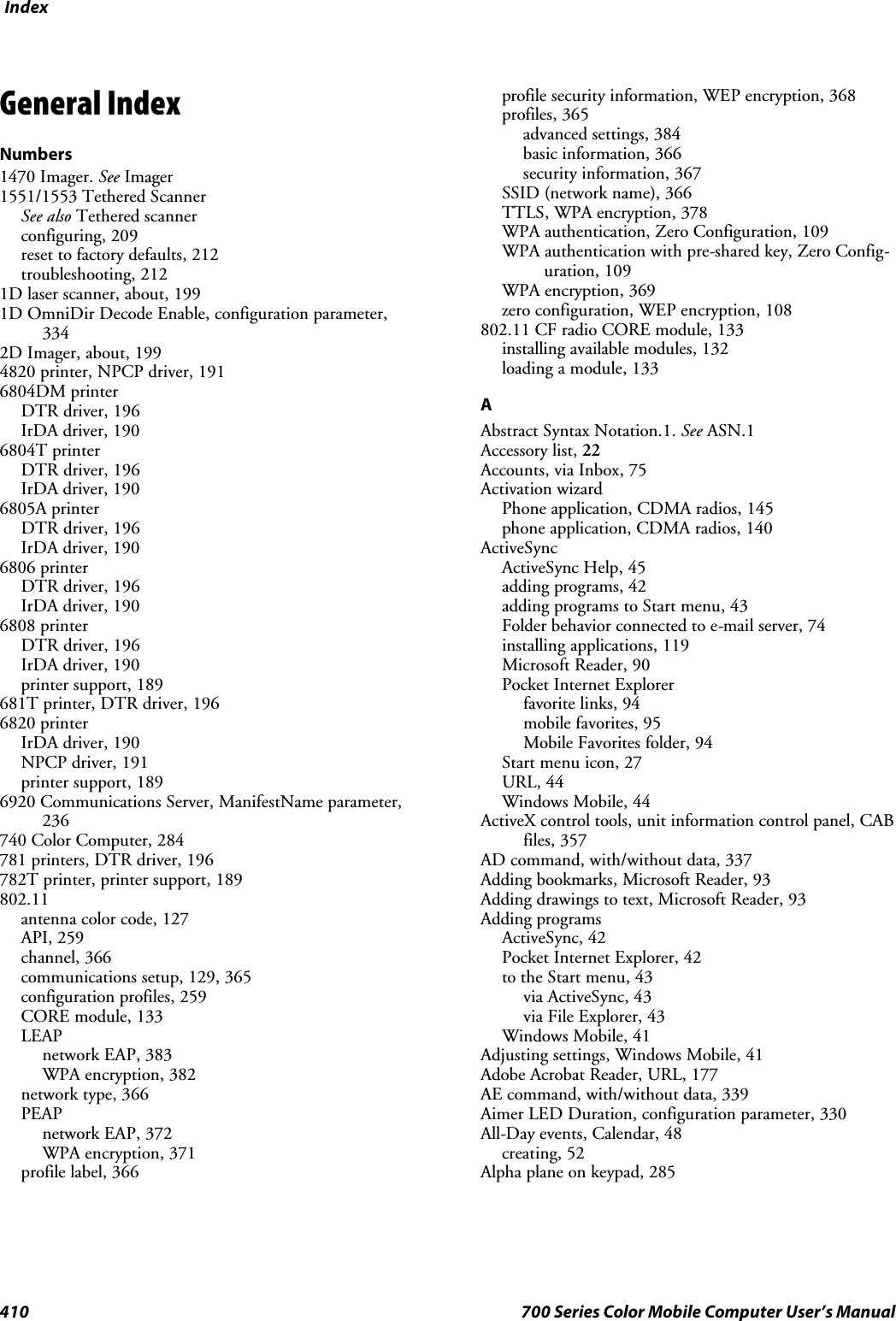
![Index411700 Series Color Mobile Computer User’s ManualAlphanumeric keypadalpha (blue) key sequences, 15[gold/white] key sequences, 13registry settingsalpha plane, 285gold plane, 285unshifted plane, 285scan codes, 288Ambient lighting, 2Annotations index, Microsoft Reader, 93Antenna, radio type, 127APIs802.11, 259AT command interface, 177IrSock, 190App launch, control panel applet, 361Application keysapp launch control panel applet, 361wakeup mask control panel applet, 360AppointmentsCalendaradding a note, 54assigning to a category, 56changing, 51creating, 51deleting, 58finding, 58making recurring, 55setting a reminder, 53viewing, 49via Calendar, 46APS linear imager, about, 199ASCIIprinting, 190printing to a port, port print method, 190raw text to printer, 190ASN.1, 187AT command interface, 177testing, 178Attaching notes to text, Microsoft Reader, 93Audio, phone application, 155Audio control panel applet, input mixing, 8Audio files, Windows Media Player, 89Audio systemexternal headset jack, 4microphone, 4speaker, 3AutoCab, command line syntax, 124AutoFTP, 240AutoIP, 186Automatic Private IP. See AutoIPAutomatic shutoffbar code configuration, 385, 390configuration parameter, 385Autostart FTP, 240AvantGo channels, Pocket Internet Explorer, 96AXCommunication, 357AXFileTransfer, 357AXReaderCommand, 357AXVWedge, 357BBacklight control panel appletambient light sensor, 2keypad, 11Backlight timeoutbar code configuration, 386, 390configuration parameter, 386Bar code configurationaudio volume, 385automatic shutoff, 385backlight timeout, 386key clicks, 386Bar codesconfigurationaudio volume, 389automatic shutoff, 390backlight timeout, 390Code 39, 389key clicks, 391internal scanner supported symbologies, 203scanning labels, 389supported symbologies, 295symbologiesCodabar, 394Code 11, 394Code 128, 396Code 39, 394Code 39 concatenation, 395Code 39 full ASCII, 395Code 93, 395Data Matrix, 397EAN, 397I 2 of 5, 398Matrix 2 of 5, 398MaxiCode, 398Micro PDF417, 399MSI code, 400PDF417, 398Plessey, 399QR code, 400S 2 of 5, 400Telepen, 401UPC, 401tethered scanner supported symbologies, 213Batteryambient lighting, 2low battery conditions, 6RAM maintenance, 6status, 5Battery status, unit information control panel applet, 355](https://usermanual.wiki/Intermec-Technologies/2610CF.700C-User-Manual-1-of-3/User-Guide-527885-Page-433.png)
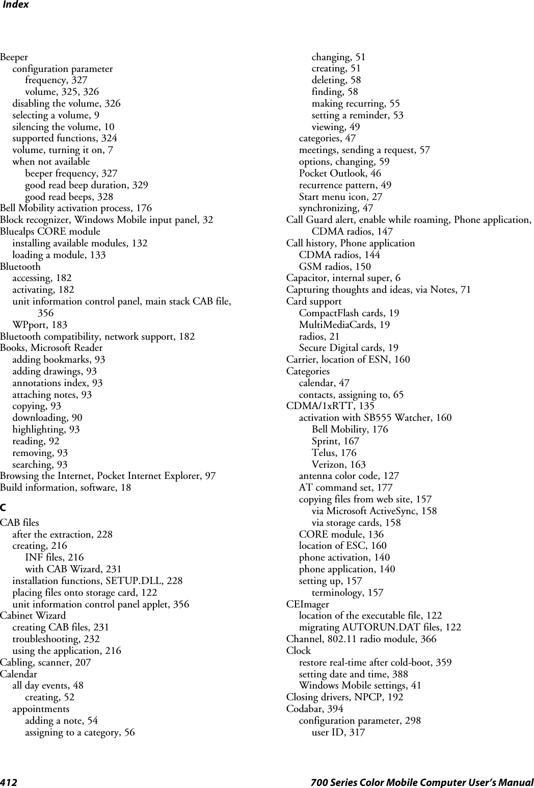
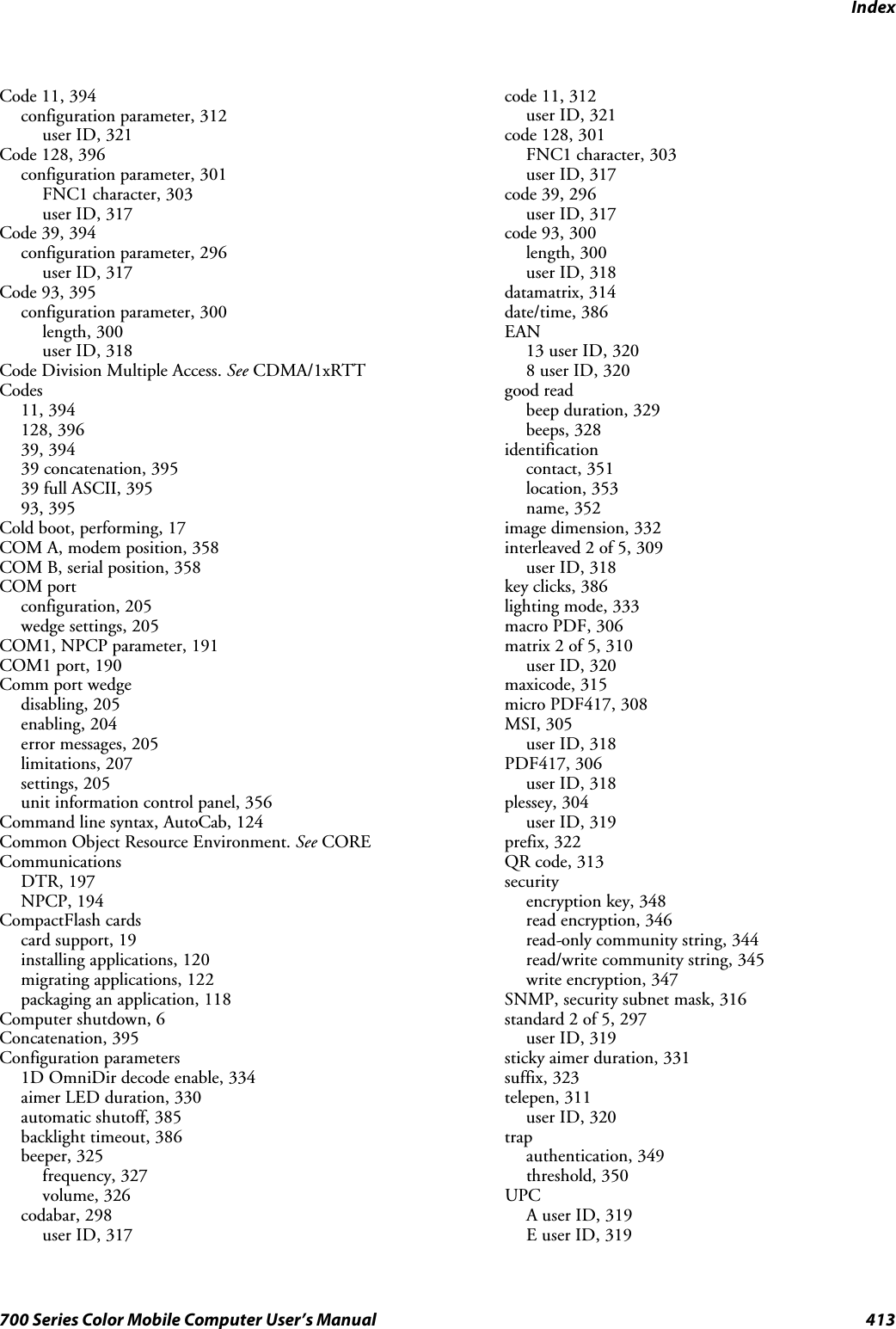
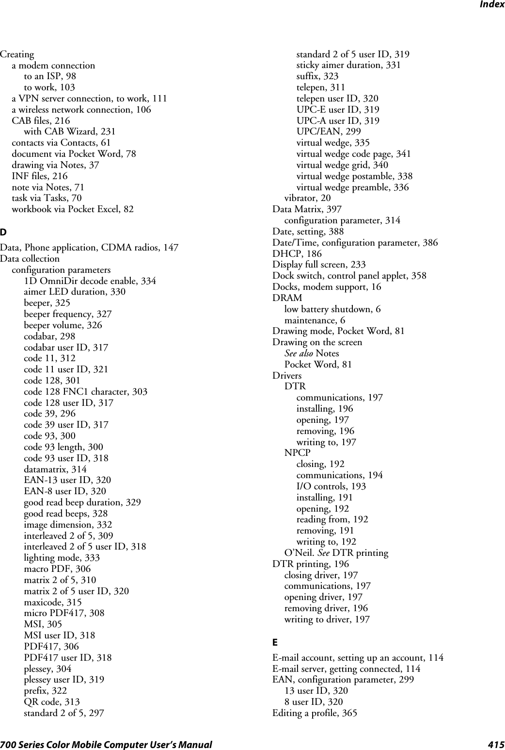
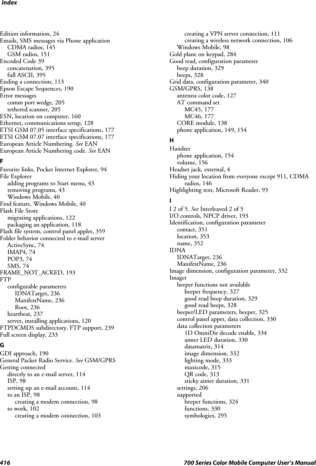
![Index417700 Series Color Mobile Computer User’s Manualsymbologies not availableCIP 128 French Pharmaceutical, 302Code 11, 312Code 128 FNC1 character, 303EAN 128 ]C1, 302Macro PDF, 306Matrix 2 of 5, 310micro PDF417, 308Telepen, 311symbology user IDs not availableCodabar, 317Code 11, 321Code 128, 317Code 39, 317Code 93, 318EAN 13, 320EAN 8, 320Interleaved 2 of 5, 318Matrix 2 of 5, 320MSI, 318PDF417, 318Plessey, 319Standard 2 of 5, 319Telepen, 320UPC A, 319UPC E, 319vibrator, enabling, 20IMAP4, Folder behavior connected to e-mail server, 74Inboxaccounts, 75composing/sending messages, 77connecting to a mail server, 75downloading messages from server, 76getting connected, 98managing e-mail messages and folders, 74Pocket Outlook, 73Start menu icon, 27synchronizing e-mail messages, 73using My Text, 39INF files, creating, 216Input Mixing, Audio control panel applet, 8Input panelblock recognizer, 32keyboard, 31letter recognizer, 33Pocket Word, 79selecting typed text, 33transcriber, 33Windows Mobile, 28word suggestions, 31Installation functions, SETUP.DLL, 228Installing applicationsusing a storage card, 120using CompactFlash cards, 120using Secure Digital cards, 121with ActiveSync, 119with FTP Server, 120Installing driversDTR, 196NPCP, 191Instant messaging, 84Integrated scanners. See Internal scannersInterface specifications, ETSI GSM 07.0x, 177Interleaved 2 of 5, 398configuration parameter, 309user ID, 318Intermec part numbers, 22Intermec settings, 294, 342beeper volume, 10vibrator, 21INTERMEC_PACKET_DRIVER, SwitchPacketDriver(),280Internal scannersconfiguring, 202supported symbologies, 203Internet explorersoftware build version, 18Windows Mobile 2003 edition, 24Internet Service Provider. See ISPIOCTL_NPCP_BIND, 193IOCTL_NPCP_CANCEL, 193IOCTL_NPCP_CLOSE, 193IOCTL_NPCP_ERROR, 193IOCTL_NPCP_FLUSH, 193IrDA printing, 190ISPconnecting to via Windows Mobile, 98creating, a modem connection, 98Pocket Internet Explorer, 94Windows Mobile, 98ITC_KEYBOARD_CHANGE, CreateEvent(), 286ITU-T interface specifications, 177KKeeping a to-do list, via Tasks, 69Key clicksbar code configuration, 386, 391configuration parameter, 386Key sequencesalpha (blue) keysalphanumeric, 15numeric, 14[gold]keys,numeric,12[gold/white] keys, alphanumeric, 13KeyboardSee also KeypadWindows Mobile input panel, 31](https://usermanual.wiki/Intermec-Technologies/2610CF.700C-User-Manual-1-of-3/User-Guide-527885-Page-439.png)
![Index418 700 Series Color Mobile Computer User’s ManualKeypadadvanced remapping, 286alphanumericalpha (blue) key sequences, 15[gold/white] key sequences, 13scan codes, 288backlight control panel applet, 11change notification, 286driver registry settings, 286numericalpha (blue) key sequences, 14[gold] key sequences, 12scan codes, 287planes, 284remapping, 284sample registry keys, 290LLaser scannerconfiguration parameters, 292data collection parametersbeeper frequency, 327beeper volume, 326codabar, 298codabar user ID, 317code 11, 312code 11 user ID, 321code 128, 301code 128 FNC1 character, 303code 128 user ID, 317code 39, 296code 39 user ID, 317code 93, 300code 93 length, 300code 93 user ID, 318EAN-13 user ID, 320EAN-8 user ID, 320good read beep duration, 329good read beeps, 328interleaved 2 of 5, 309interleaved 2 of 5 user ID, 318macro PDF, 306matrix 2 of 5, 310matrix 2 of 5 user ID, 320micro PDF417, 308MSI, 305MSI user ID, 318PDF417, 306PDF417 user ID, 318plessey, 304plessey user ID, 319prefix, 322standard 2 of 5, 297standard 2 of 5 user ID, 319suffix, 323telepen, 311telepen user ID, 320UPC-E user ID, 319UPC-A user ID, 319UPC/EAN, 299virtual wedge, 335virtual wedge code page, 341virtual wedge grid, 340virtual wedge postamble, 338virtual wedge preamble, 336SNMP configuration parametersidentification contact, 351identification location, 353identification name, 352security encryption key, 348security read encryption, 346security read-only community string, 344security read/write community string, 345security subnet mask, 316security write encryption, 347trap authentication, 349trap threshold, 350supportedbeeper functions, 324symbologies, 295symbologies not availableDatamatrix, 313datamatrix, 314maxicode, 315LEAP802.11 radio modulenetwork EAP, 383WPA encryption, 382profile security information, 381WEP encryption, 381Letter recognizer, Windows Mobile input panel, 33Letting your location be visible, CDMA radios, 146Library, Microsoft Reader, 91Lighting Mode, configuration parameter, 333Line printing, 190Location, Phone application, CDMA radios, 146LPT9 printer device, 191MMacro PDF, configuration parameter, 306Managing e-mail messages and folders, via Inbox, 74Matrix 2 of 5, 398configuration parameter, 310user ID, 320MaxiCode, 398configuration parameter, 315MeetingsCalendar, sending a request, 57via Calendar, 46Menus, Windows Mobile settings, 41Messagessending to, contacts, 66via Inboxcomposing/sending, 77downloading from server, 76MIBsASN.1, 187files, 187object identifier, 188OIDs, 188](https://usermanual.wiki/Intermec-Technologies/2610CF.700C-User-Manual-1-of-3/User-Guide-527885-Page-440.png)
![Index419700 Series Color Mobile Computer User’s ManualMicro PDF417, 399configuration parameter, 308Microphone, 4phone application, 154Microsoft Developer Network Library. See MSDN libraryMicrosoft Exchange e-mail account, 84Microsoft Passport account, 84Microsoft Readerbooksdownloading, 90reading, 92removing, 93features, 93adding bookmarks, 93adding drawings, 93annotations index, 93attaching notes, 93copying text, 93highlighting text, 93searching for text, 93using the library, 91Windows Mobile, 90Microsoft’s Wireless Zero Config, 365Migrating applicationsFlash File Store, 122CompactFlash storage cards, 122Secure Digital storage cards, 122Migrating to a 700 Color Computer, 124Mobile Favorites, Pocket Internet Explorer, 95Mobile Favorites folder, Pocket Internet Explorer, 94Modem position, COM A, 358Modems, creating a connectionto an ISP, 98to work, 103MP3 files, Windows Media Player, 89MSDN library, 240MSDN Windows CE documentation, 186MSI, 400configuration parameter, 305user ID, 318MSN Messengerabout, 84accountsMicrosoft Exchange e-mail, 84Microsoft Passport, 84contactsmanaging, 87sending messages, 88working with, 86setting up an account, 85using My Text, 39MultiMediaCards, card support, 19NNDIS_SUPP_LOGGING_OFF, EnableSuppLogging(),279NDIS_SUPP_LOGGING_ON, EnableSuppLogging(),279NDISUIO_PACKET_DRIVER, SwitchPacketDriver(),280Network adaptersantenna color code, 127Ethernet communications, 128no networking, 130wireless 802.11, 129wireless printing, 182Network EAPLEAP security method, 383PEAP security method, 372Network settings, Phone application, GSM radios, 153Network type, 802.11 radio module, 366NLED driver, vibrator, 281NLED_SETTINGS_INFO_ID, NLEDSetDevice, 282Notesadding toappointments, 54contacts, 64creating a note, 71drawing on the screen, 37creating a drawing, 37selecting a drawing, 37Pocket Outlook, 71recording a message, 38Start menu icon, 27synchronizing notes, 72writing on the screen, 34alternate writing, 35converting writing to text, 35selecting the writing, 34tips for good recognition, 36NPCP printing, 191about, 191closing driver, 192COM1 parameters, 191communications, 194driver I/O controls, 193installation, 191LPT9, 191opening driver, 192reading from driver, 192removal, 191sample code, 194unit information control panel, NPCPTEST CAB file,356writing to driver, 192Numeric keypadalpha (blue) key sequences, 14[gold] key sequences, 12registry settingsalpha plane, 285gold plane, 285unshifted plane, 285scan codes, 287OO’Neil printingSee also DTR printerinstalling driver, 196Object Store, packaging an application, 118](https://usermanual.wiki/Intermec-Technologies/2610CF.700C-User-Manual-1-of-3/User-Guide-527885-Page-441.png)