Intermec Technologies 2610CF 2610CF User Manual CN2Busermanual
Intermec Technologies Corporation 2610CF CN2Busermanual
UserManual.wiki
>
Intermec Technologies
>
2610CF User Manual
>
User Manual 2 of 3
Contents
1.
700C User Manual 1 of 3
2.
700C User Manual 2 of 3
3.
700C User Manual 3 of 3
4.
CN2 Users Manual 1 of 2
5.
CN2 Users Manual 2 of 2
6.
Compliance Statement Insert
7.
Users Manual
8.
User Manual 1 of 3
9.
User Manual 2 of 3
10.
User Manual 3 of 3
11.
Compliance Insert
User Manual 2 of 3
Navigation menu
Upload a User Manual
Namespaces
Wiki Guide
HTML
PDF
Info
Views
User Manual
Discussion / Help
Navigation
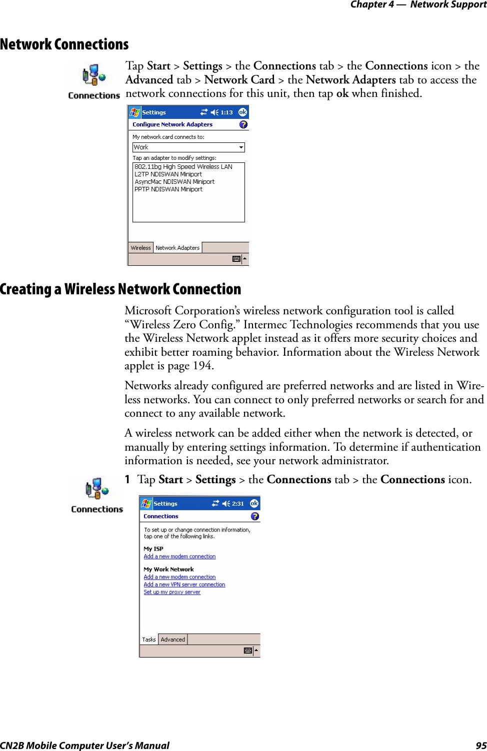
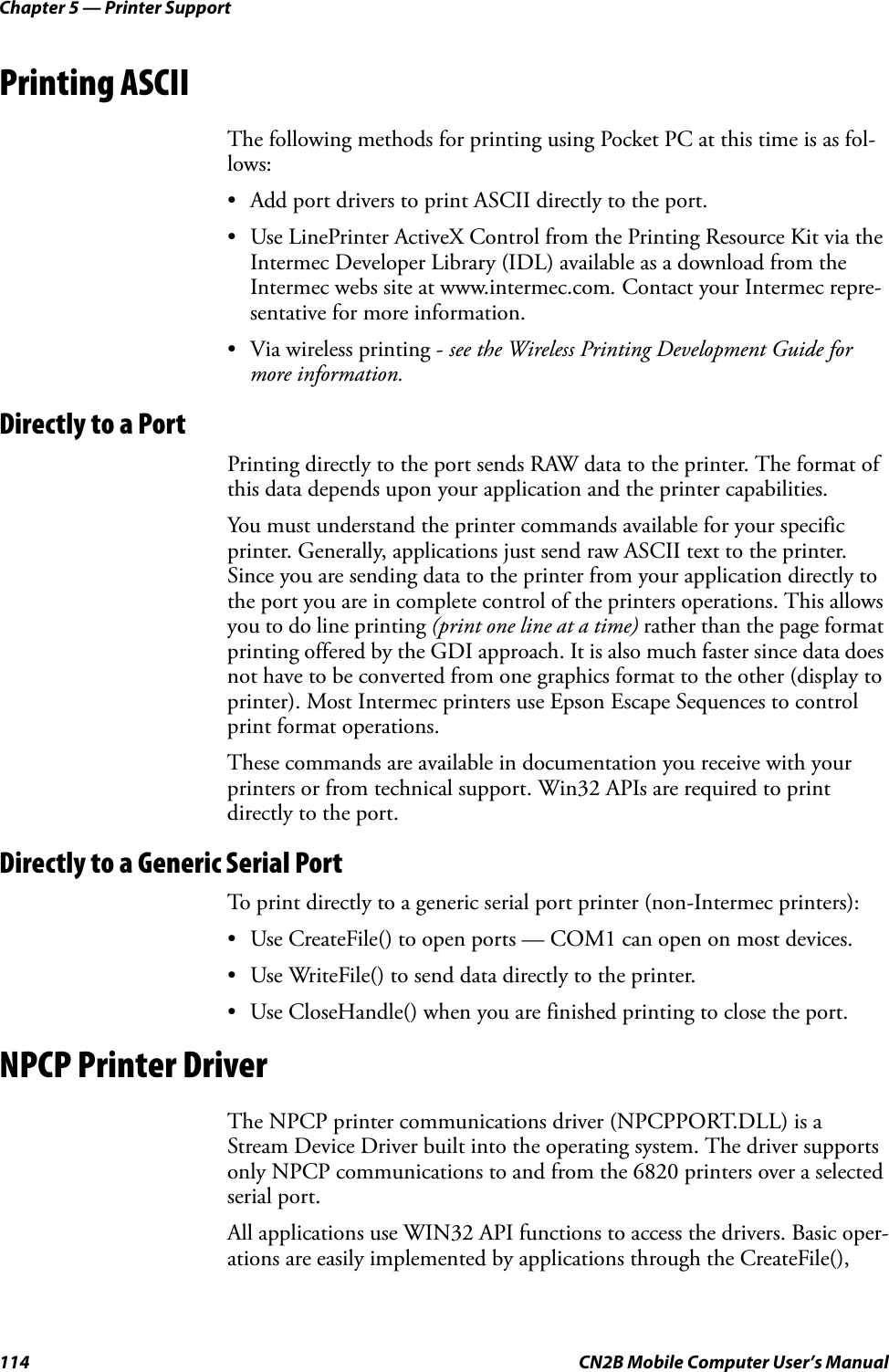
![Chapter 5 — Printer SupportCN2B Mobile Computer User’s Manual 115WriteFile(), ReadFile(), DeviceIOControl(), and CloseHandle() Win32 APIs.Operations to upgrade printer modules, perform printer diagnostics, and get printer configuration are performed largely via DeviceIOControl() functions.About NPCPNPCP (Norand® Portable Communications Protocol) is a proprietary pro-tocol that provides session, network, and datalink services for Intermec mobile computers in the Intermec LAN environment used with printers and data communications.NPCP Driver Installation and RemovalUse LPT9: for the NPCP printer device and COM1 for the last parameter. COM1 is the connection available via the CN2B Computer.Applications use the RegisterDevice() function to install the driver. Dereg-isterDevice() uninstalls the device driver and frees memory space when the driver is not required. Use the HANDLE returned by RegisterDevice() as the parameter to DeregisterDevice().Use the RegisterDevice() function call as demonstrated below. Specify the full path name to the driver starting at the root for the RegisterDevice() function to work properly. The last parameter to RegisterDevice() is a DWORD that represents the name of the port for the NPCP stream driver to use. Build this parameter on the stack if it is not to be paged out during the call. The first parameter “LPT” (Device Name) and the second parame-ter “9” (index), indicate the name of the registered device, such as LPT9. This is used in the CreateFile() function call.Install(){HANDLE hDevice;TCHAR port[6];port[0] = TCHAR(‘C’);port[1] = TCHAR(‘O’);port[2] = TCHAR(‘M’);port[3] = TCHAR(‘1’);port[4] = TCHAR(‘:’);port[5] = TCHAR(0);hDevice = RegisterDevice ( (TEXT(”LPT”), 9, TEXT(“\\STORAGE CARD\\WINDOWS\\NPCPPORT.dll”), (DWORD)port);}Opening the NPCP DriverThe application opens the NPCP driver by using the CreateFile() function. The call can be implemented as follows. The first parameter “LPT9:” must reflect the device name and index used in the RegisterDevice() function call and will fail for any of the following reasons:](https://usermanual.wiki/Intermec-Technologies/2610CF.User-Manual-2-of-3/User-Guide-616312-Page-41.png)
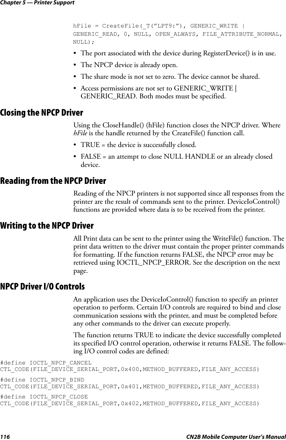
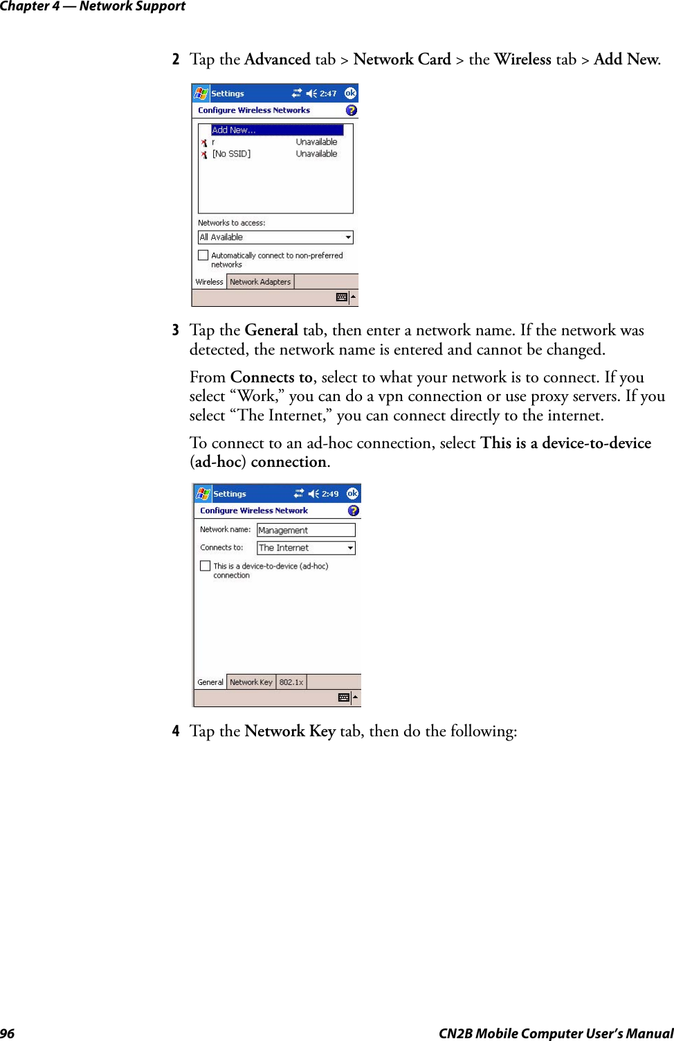
![Chapter 5 — Printer SupportCN2B Mobile Computer User’s Manual 119#define COVEROFF (BYTE)227 // printer cover off error#define HEADFAULT (BYTE)228 // printer head short or driver short error#define PFFAULT (BYTE)229 // paper feed motor fault.#define FRAME_NOT_ACKED 0x8000 // frame was not received by printer and need to be resent.O’Neil Printer DriverThe DTR printer communications driver is a Stream Device Driver named ONEIL.DLL.All applications use WIN32 API functions to access drivers. Basic opera-tions are easily implemented by applications through the CreateFile(), WriteFile(), DeviceIOControl() and CloseHandle() Win32 APIs.The driver supports communications to PB20, PB40, and PB42 printers over a selected serial port.DTR Driver Installation and RemovalYour application must install the device driver by using the RegisterDe-vice() function. The driver name is ONEIL.DLL. We recommend that you use “DTR” for the Device Name parameter, “1” for the Device Driver index parameter, and use any of the following strings for the last parameter:• NULL (==0) Defaults to COM1 @ 9600• “COM1” only COM port specified defaults to 9600• “COM1:9600” sets to COM port and specified bit rate• “COM1:19200” sets to COM port and specified bit rateUse the HANDLE returned by RegisterDevice() as the parameter to Dereg-isterDevice(). The correct usage of the RegisterDevice() function call is demonstrated below. You may use DeregisterDevice() to uninstall the driver.Install(){HANDLE hDevice;TCHAR port[6];port[0] = TCHAR(‘C’);port[1] = TCHAR(‘O’);port[2] = TCHAR(‘M’);port[3] = TCHAR(‘1’);port[4] = TCHAR(‘:’);port[5] = TCHAR(0);hDevice = RegisterDevice ( (TEXT(”DTR”), 1, TEXT(”\\WINDOWS\\ONEIL.DLL”),(DWORD)port);}](https://usermanual.wiki/Intermec-Technologies/2610CF.User-Manual-2-of-3/User-Guide-616312-Page-45.png)