Intermec Technologies 2610CF 2610CF User Manual CN2Busermanual
Intermec Technologies Corporation 2610CF CN2Busermanual
Contents
User Manual 2 of 3

CN2B Mobile Computer User’s Manual 75
3Installing Applications
There are multiple ways to get an application to your CN2B Mobile Com-
puter; like there are multiple ways to package the application for delivery.
Chapter 3 — Installing Applications
76 CN2B Mobile Computer User’s Manual
Packaging an Application
Use any of these methods to package an application for installation:
• For very simple applications, the application itself might be the only file
that needs to be delivered.
• It could be a directory structure that contains the application, supporting
files like ActiveX controls, DLLs, images, sound files, and data files.
• Or, you could package an application via a CAB file.
Consider any of the following when choosing a location into which to store
your application:
• In the basic CN2B Computer, there are two built-in storage options: the
Object Store and the Persistent Storage Manager (PSM). The Object
Store is RAM that looks like a disk. Anything copied here is deleted
when a cold-boot is performed on the CN2B Computer. The PSM is an
area of storage which is embedded in a section of the system’s FLASH
memory. This storage area is not erased during a cold-boot. It may, how-
ever, be erased during the reflashing process. In addition to storing appli-
cations and data files, you do have the option to store a persistent registry
to the PSM region.
• If the optional Secure Digital storage card is in the system, then consider
this card the primary location for placing an applications install files.
This storage card creates the “\SDMMC Disk” folder.
• Use the small nonvolatile Flash File Store region to hold CAB files that
rebuild the system at cold-boot or install applications from a CAB file
into the Flash File Store so they are ”ready-to-run” when a cold-boot is
performed. Since the FLASH in the system has a limited number of
write cycles, do not use the Flash File Store for excessive writing pur-
poses; however, reading is okay.
Files copied to any of these locations are safe when a cold-boot is performed
on a CN2B Computer — providing the AutoRun system is installed in the
appropriate location You can find this system in the CN2B Management
Tools portion. Copying a CAB file to the “\CABFILES” folder on one of
these cards automatically extracts that CAB file on every cold-boot to
ensure that your system is properly set up (see page 83).
Chapter 3 — Installing Applications
CN2B Mobile Computer User’s Manual 77
Installing Applications
Consider any of the following options to get the package to the preferred
location on your CN2B Computer: Microsoft ActiveSync, FTP Server
(page 78), Secure Digital storage cards (page 78), or Registry (page 79).
Using Microsoft ActiveSync
The Microsoft ActiveSync tool is located on the CN2B Companion CD. See
Chapter 2, “Windows Mobile 2003” for information about this tool as pro-
vided by Microsoft Corporation.
This can be a serial, USB, InfraRed, or 802.11b/g ActiveSync connection.
Files can be copied using File Explorer on a desktop or a laptop computer.
This is usually good when updating few CN2B Computers.
These instructions assume that Microsoft ActiveSync was installed onto
your desktop and is up and running. If not, go to Chapter 2, “Windows
Mobile 2003” for an URL from which to download the latest application.
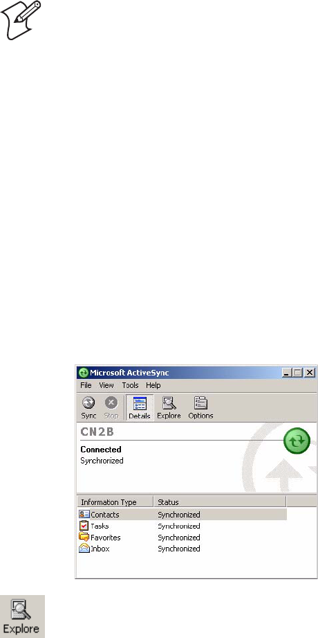
1Connect your CN2B Computer to your desktop computer via an Active-
Sync cable.
2Wait for a “Connected” message to appear in the Microsoft ActiveSync
application to signal a connection to the CN2B Computer. If necessary,
select File > Get Connected to initiate a connection.
4From your desktop, select Start > Windows Explorer, then browse the
“C:\Intermec\CN2B Mgmt Tools\CabFiles” path for any CAB files
needed for your CN2B Computer. Select the appropriate file, right-click
the file for a pop-up menu, then select Copy.
Note: These instructions assume the CN2B Management Tools were
installed on your desktop.
3Click Explore to access the Mobile Device folder on your unit.
Chapter 3 — Installing Applications
78 CN2B Mobile Computer User’s Manual
5Within the Mobile Device directory, go to the directory where you want
the files located on the CN2B Computer, do a right-click for a pop-up
menu, then select Paste.
6When all of the files are pasted, perform a warm-boot on the CN2B
Computer. When the computer reboots, wait for the LED on the top
left of your keypad to stop blinking. Tap Start > Programs > File
Explorer to locate the newly copied executable files, then tap these files
to activate their utilities.
Using the FTP Server
The CN2B Computer has a built-in FTP Server that connects to a network
via 802.11b/g or WAN (Wireless Access Network). This allows connec-
tions to the CN2B Computer to perform file transfers or computer man-
agement functions. Another benefit is you can create FTP scripts to
automate the process of copying files to the CN2B Computer. This option
is good for when a large number of CN2B Computers need updating. See
Chapter 7, “Programming” for more information.
Copying a Secure Digital Storage Card
Use the following steps to install an application using a Secure Digital stor-
age card:
1Suspend the CN2B Computer and remove its Secure Digital drive,
which holds a Secure Digital storage card.
2Using a Secure Digital Adapter card, place the Secure Digital drive in
your desktop PC card drive.
3Create a subdirectory on the PCMCIA Secure Digital drive in which to
store your application.
4Copy your application, data files, and all required DLLs and drivers to
the subdirectory created on the Secure Digital drive.
5Add your application to the AUTOUSER.DAT file on the “\SDMMC
Disk\2577” directory with the following statement:
RUN=\<your directory>\<yourapp.exe>
where your directory is the directory on the Secure Digital storage card
where the application was installed, and yourapp.exe is the name of your
application. Finish the “RUN=” statement with a carriage return linefeed
combination. There may be multiple run statements in the file.
6Remove the Secure Digital card from your desktop and reinstall it into
the CN2B Computer.
7Warm-boot the CN2B Computer to add these files to the Secure Digital
storage card.
If the AUTOUSER.DAT file is found and the “RUN=” statement is cor-
rect, the task manager launches and executes your program on startup.
Chapter 3 — Installing Applications
CN2B Mobile Computer User’s Manual 79
Replicating Settings Using the Registry
The following information updates the registry on your CN2B Computer,
confirms the registry update, then copies the information onto other CN2B
Computers in your network.
If you are using DHCP, no changes are necessary.
If using Static IP, the new CN2B Computer has the IP address of the origi-
nal CN2B Computer because the copied registry includes this information.
When you change the IP address using the Intermec Settings applet, the
information is lost when a warm-boot is performed, and the original IP
address is used.
Load the REGFLUSH.CAB file before running the Registry Save applica-
tion. Once you do, performing a warm-boot keeps the new IP address.
To install the Registry Save application after a cold-boot is performed,
change the properties of the REGFLUSH.CAB file to that of read-only.
Using ActiveSync, copy the CAB file to the “Flash File Store\CabFiles”
folder on the CN2B Computer, then perform a cold-boot to load this file.
Deleting the Old Registry File
2Look for a “registry” file. If one exists, select to highlight that file, press
and hold for a pop-up menu, select Delete, then Yes to remove this file.
Using the RegFlush CAB File
Contact your Intermec representative about getting a copy of the
REGFLUSH.CAB file.
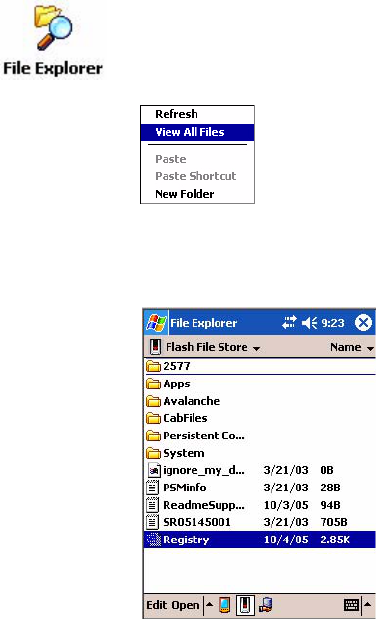
1On the original CN2B Computer, select Start > Programs > File
Explorer, then tap My Device > Flash File Store. Scroll down to the bot-
tom of the list of files and folders, press and hold your stylus in the white
area beneath for a pop-up menu, then select View All Files.
Chapter 3 — Installing Applications
80 CN2B Mobile Computer User’s Manual
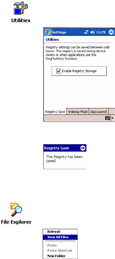
Loading the Registry Save Application
1On the CN2B Computer, tap the REGFLUSH.CAB file to load the
“Registry Save” application.
2Set up the CN2B Computer to your specifications using the Intermec
Settings applet and other applets.
4Select Start > Registry Save, then tap ok when told the registry is saved.
Confirming the New Registry File
To confirm whether the new registry file exists, do the following:
3Select Start > Settings > the System tab > the Utilities icon > the Regis-
try Save tab, then check Enable Registry Storage to enable the registry
save flag. Tap ok to close, then close the Settings.
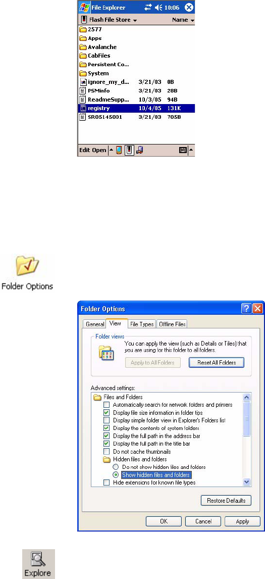
1On the CN2B Computer, select Start > Programs > File Explorer, then
tap My Device > Flash File Store. Press and hold your stylus in the white
area beneath for a pop-up menu, then select View All Files.
Chapter 3 — Installing Applications
CN2B Mobile Computer User’s Manual 81
2The new registry file should be on the root of the Flash File Store folder
with today’s date.
Updating Other Computers in Your Network
These instructions assume you have Windows XP on your desktop.
1Connect your CN2B Computer to your desktop using Microsoft Active-
Sync and a cradle. Make sure the ActiveSync application on your desk-
top is up and running and connected to your CN2B Computer.
2On your desktop, select Start > Settings > Control Panel, double-click
Folder Options, then click the View tab. Beneath “Hidden files and
folders,” check Show hidden files and folders, then click OK to close.
3Using the Microsoft ActiveSync application on your desktop, click
Explore to access the Flash File Store folder on your CN2B Computer
and locate the “registry” file. Copy this file, then paste it in a temporary
location on your desktop.
Chapter 3 — Installing Applications
82 CN2B Mobile Computer User’s Manual
4Remove the CN2B Computer from the cradle, and put another CN2B
Computer in its place. The ActiveSync application on your desktop
should connect to the new unit.
5Follow the instructions for “Deleting the Old Registry File” on page 79,
put the new registry file in the root of the Flash File Store folder on the
new CN2B Computer, enable the registry save flag via the Utilities
applet, perform a warm-boot. and make sure these settings are saved.
Updating the System Software
You can use the Intermec Recovery CD to reinstall or update the operating
system software on the CN2B Computer. For more information, contact
your Intermec representative.
Migrating from Another Computer
As you migrate from another mobile computer to a CN2B Computer, you
need to consider the following: When converting an application to run on
the CN2B Computer, most APIs should work without changes. Below are
a few exceptions:
• The other computer may use the “\Storage Card” folder for nonvolatile
storage. You may need to change the application to store data onto the
“SDMMC Disk” folder instead of the “\Storage Card” folder if a Secure
Digital storage card is present in the system.
• If the application uses the RegFlushKey() API, it must first verify that
the proper media is available in the system.
• Some WAN radio options have changed. Review the WAN radio infor-
mation in Chapter 4, “Network Support” to determine if any changes
are required in your application.
• Keyboard remapping is available on the CN2B Computer should you
need to map these keys like that of the original computer (see page 104).
• Special Resource Kits are not needed to compile applications for the
Xscale processor. Targeting the SA1110 processor creates applications
that run on the CN2B Computer.
Chapter 3 — Installing Applications
CN2B Mobile Computer User’s Manual 83
Installing Cabinet Files
CAB files (short form of “cabinet” files) are compressed folders as defined by
Microsoft. A “cabinet” file is a single file, usually suffixed with .CAB, that
stores compressed files in a file library. A compressed file can be spread over
several cabinet files. During installation, the setup application decom-
presses the files stored in a cabinet and copies them to the user’s system.
For the CN2B Computer, CAB files register DLLs, create shortcuts, mod-
ify registry entries, and run custom setup programs. Tap a CAB file to
extract that file or place the CAB file on one of the approved storage devices
in the “\CabFiles” folder, then perform a warm-boot on the CN2B Com-
puter. There are two methods available to extract a CAB file:
• Tap a CAB file to extract it. With this method, the CAB file is automat-
ically deleted when the extraction process is successful, unless the CAB
file is set with the read-only attribute.
• Use AUTOCAB to extract all files when a cold-boot is performed on the
CN2B Computer. See the Software Tools User’s Manual for information.
Chapter 3 — Installing Applications
84 CN2B Mobile Computer User’s Manual

CN2B Mobile Computer User’s Manual 85
4Network Support
This chapter includes information about the different networks supported
by the CN2B Mobile Computer, and ways to configure and manage those
networks. Note that the CN2B Mobile Computer automatically installs the
appropriate software for radio or phone use when the unit is turned on.
Below are the main topics of this chapter:
• Personal Area Networks (page 86)
• Local Area Networks (page 92)
• Wide Area Networks (page 100)
• Remote Access (Modems) (page 101)
• Management (page 108)
Chapter 4 — Network Support
86 CN2B Mobile Computer User’s Manual
Personal Area Networks
“Bluetooth” is the name given to a technology standard using short-range
radio links, intended to replace the cables connecting portable and fixed
electronic devices. The standard defines a uniform structure for a wide
range of devices to communicate with each other, with minimal user effort.
Its key features are robustness, low complexity, low power, and low cost.
The technology also offers wireless access to LANs, the mobile phone net-
work, and the internet for a host of home appliances and mobile computer
interfaces.
Information about other Bluetooth software is in the Bluetooth Resource
Kit and the Wireless Printing Development Guide via the Intermec Devel-
oper Library (IDL), which is available as a download from the Intermec
web via www.intermec.com. Contact your Intermec representative for
more information.
About the Application
•If Bluetooth is active, and a warm-boot was performed, the CN2B Com-
puter boots up with the Bluetooth state activated and Bluetooth virtual
COM ports (such as printing) registered. However, you must reactivate
connections, as the system does not do these automatically.
•If Bluetooth is inactive, and a warm-boot was performed, the CN2B
Computer boots up with Bluetooth deactivated.
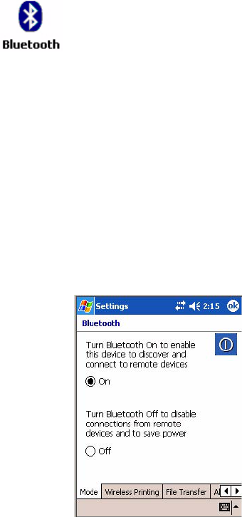
Mode
The default tab activates or deactivates Bluetooth. When Bluetooth is acti-
vated, the CN2B Computer discovers and connects to remote devices.
Bluetooth is not started automatically by default after a cold-boot is per-
formed. To run Bluetooth, tap Start > Settings > the Connections tab >
the Bluetooth icon. The CN2B Computer retains the Bluetooth state when
warm-boots are performed, for example:
Chapter 4 — Network Support
CN2B Mobile Computer User’s Manual 87
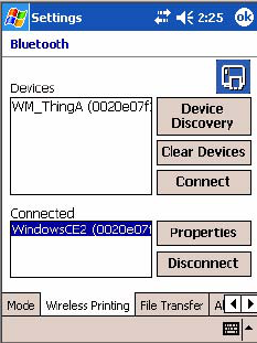
Wireless Printing
Use this tab to print via Bluetooth devices. Tap Device Discovery to dis-
cover (or scan) for remote Bluetooth devices. When the CN2B Computer
is finished scanning, any newly discovered devices appear in the upper
Devices box.
Tap Clear Devices to remove the list from the Devices box.
To print to a Bluetooth device, select any of the devices listed in the
Devices box, then tap Connect. Once connected, the selected device moves
to the lower Connected box.
To view connection information or register a COM port for a device, from
the lower Connected box, select a device, then tap Properties. See “Proper-
ties” on the next page for information.
When done printing to a device, select that device in the Connected box,
then tap Disconnect. This moves the device in question back to the upper
Devices box.
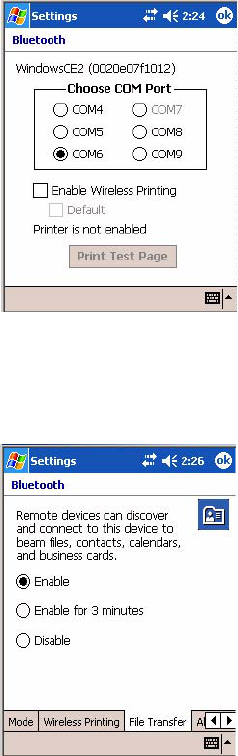
Properties
Select a COM Port from the Choose COM Port box to register for this
device, then check Enable Wireless Printing to complete the COM port
registration. To change your COM port selection, clear (uncheck) the
Enable Wireless Printing box, select a new COM port, then check Enable
Wireless Printing again. Check Default COM ports already in use are
grayed out.
When you enable Wireless Printing, a status message is shown near the bot-
tom of the screen to confirm your action. To print a test page to your
printer, tap Print Test Page.
Check Default to set this printer to identify the assigned COM Port as the
WPPort in the registry. See the Wireless Printing Development Guide for
more details on WPPort.
Chapter 4 — Network Support
88 CN2B Mobile Computer User’s Manual
Tap ok to return to the Wireless Printing page.
File Transfer
Use this page to enable your unit to receive files from another Bluetooth
device, or from any device that supports this function.
Chapter 4 — Network Support
CN2B Mobile Computer User’s Manual 89
Connecting with Bluetooth
Before you connect to the network, make sure Bluetooth is enabled on your
CN2B Computer so you can discover and connect to remote devices.
Also make sure Bluetooth is enabled on your mobile phone. For example,
with the Nokia 3650, go to its menu, select Connect > Bluetooth, then set
My phone’s visibility to “Shown to all.”
Do the following to establish a Bluetooth connection between your CN2B
Computer and your mobile phone, then establishing a dial-up networking
session with your wireless network. Once connected, you should be able to
browse Internet websites and use other online resources from your CN2B
Computer.
Note: While these instructions apply to many Bluetooth devices, these
instructions use the Nokia 3650 for example purposes.
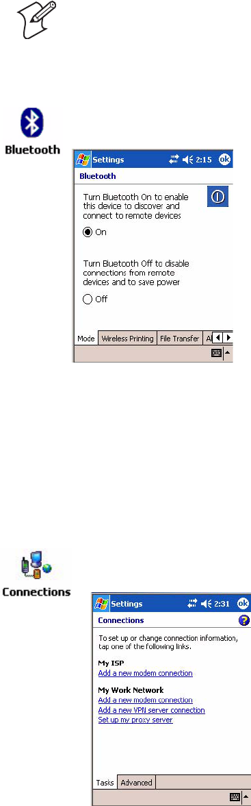
Tap Start > Settings > the Connections tab > the Bluetooth icon. Tap On
to activate Bluetooth, then tap ok to exit the applet.
1Tap Start > Settings > the Connections tab > the Connections icon,
then tap Add a new modem connection.
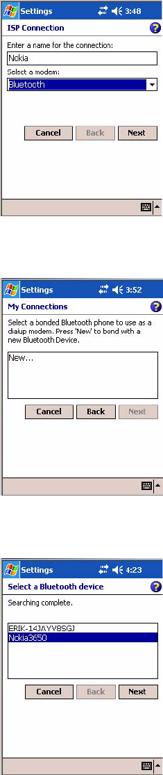
Chapter 4 — Network Support
90 CN2B Mobile Computer User’s Manual
2Enter a name for the connection, such as “Nokia.” In the Select a
modem list, select “Bluetooth,” then tap Next to continue.
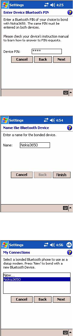
3Tap New... if the phone is not listed in the known devices. Make sure
your Bluetooth device is turned on before you start the search.
4When the discovery of devices is complete, select your Bluetooth device,
then tap Next to continue.
Chapter 4 — Network Support
CN2B Mobile Computer User’s Manual 91
5Enter the correct Device PIN on both the Bluetooth device and the
CN2B Computer, then tap Next to continue.
6Enter a name for the device if needed, then tap Finish.
7After bonding completes, select your Bluetooth device from the list of
bonded devices, then tap Next.
Chapter 4 — Network Support
92 CN2B Mobile Computer User’s Manual
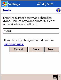
8Enter the appropriate number as it should be dialed for your Bluetooth
connection, then tap Next to continue. Enter the user name, password,
and domain required for your Bluetooth device, then tap Finish.
Now you can establish a connection to your network via the Internet
Explorer application. To disconnect, tap the Connectivity icon in the top
menu bar, then select Disconnect.
Local Area Networks
By default, the CN2B Computer comes with a 802.11b/g radio and Blue-
tooth. The CN2B Computer is capable of supporting 802.11i security
requirements.
The CN2B Computer is a versatile mobile computer that you can easily
add to your wired or wireless data collection network. You can connect
your CN2B to your network using:
• USB communications
• 802.11b/g radio communications
Configuring USB Communications
You can place the CN2B in the modem dock (P/N: 075499) or the com-
munications dock (P/N: 225-696-001) to transfer data to and receive data
from another device using USB communications. The USB cable, commu-
nications dock, and modem dock are sold separately. For more information
on accessories and how to order them, see “Accessories” on page 15.
To use USB communications with your CN2B Computer
1Connect the communications dock to the USB port of the other device
using an appropriate USB cable.
2Make sure that your USB device is configured for USB communications.
3Insert the CN2B Computer into the communications dock.
4Turn on the CN2B Computer.

Chapter 4 — Network Support
CN2B Mobile Computer User’s Manual 93
Configuring 802.11b/g Radio Communications
The wireless CN2B has an internal 802.11b/g radio to transfer data using
wireless communications. This manual assumes you have already set up
your wireless communications network, including your access points. If
you are using a UDP Plus network, you also need to have your Intermec
Application Server communicating with a host computer.
Your CN2B Computer supports TCP/IP and UDP Plus.
Configuring the Network Parameters for a TCP/IP Network
In a TCP/IP network, the CN2B Computer communicates with a host
computer directly using TCP/IP. The access point acts as a bridge to allow
communications between the wired and wireless networks.
1Configure the infrastructure mode, network name (SSID), host IP
address, and IP settings (if not using DHCP) on each CN2B Computer
in the network.
2Configure security. For help, see “Configuring Your Wireless Network”
on page 195.
The easiest way to configure the network parameters on the CN2B Com-
puter is to use the Intermec Settings applet. For help, see “Intermec Set-
tings Applet” on page 191.
Configuring the Network Parameters for a UDP Plus Network
In a UDP Plus network, the CN2B Computer communicates with a host
computer through the Intermec Application Server. The Intermec Applica-
tion Server translates UDP Plus packets on the wireless network into
TCP/IP packets on the wired network and vice versa. The access point acts
as a bridge to allow communications between wired and wireless networks.
1Configure the network name (SSID), controller IP address, IP settings
(if not using DHCP), and controller port (set to 5555) on each CN2B
Computer in the network.
2Configure security. For help, see “Configuring Your Wireless Network”
on page 195.
The easiest way to configure the network parameters on the CN2B Com-
puter is to use the Intermec Settings applet. For help, see “Intermec Set-
tings Applet” on page 191.
Make sure all components with antennas are at least 30 cm (1 ft) apart
when power is applied. Failure to comply could result in equipment
damage.
Chapter 4 — Network Support
94 CN2B Mobile Computer User’s Manual
Network Adapters
The CN2B Computer has the 802.11b/g radio and wireless printing. It
does not have an external antenna. Other radios are not supported. See the
Developer’s Support web site for information on network adapters.
Wireless 802.11 Communications
No Networking
Network Selection APIs
These APIs change the network adapter configuration programmatically.
Both drivers support the same IOCTL function numbers for loading and
unloading the drivers. Go to Chapter 7, “Programming” to see the APIs.
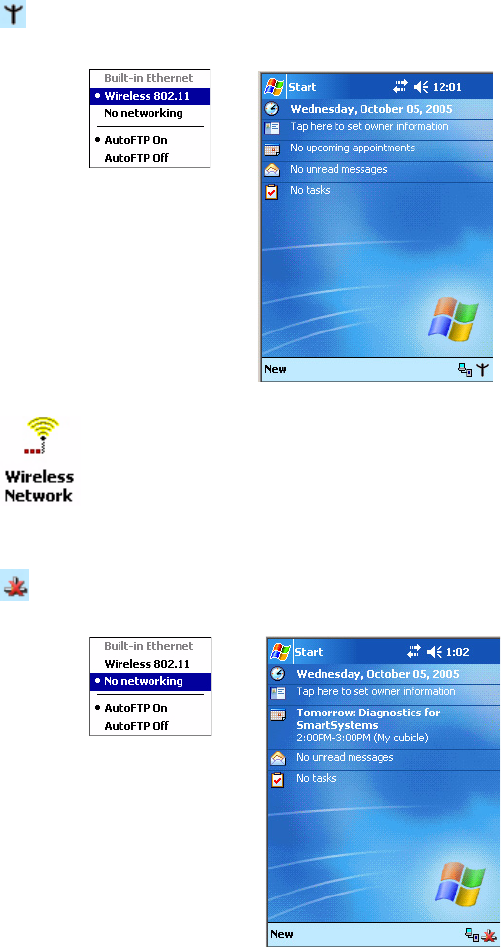
When “Wireless 802.11” is selected via the NDISTRAY pop-up menu, the
Wireless 802.11 antenna icon shown to the left appears in the system tray.
To configure wireless 802.11 communications on the CN2B Computer,
tap Start > Settings > the System tab > the Wireless Network icon. Go to
Appendix A, “Configurable Settings” for information.
When “No networking” is selected via the NDISTRAY pop-up menu, the
disconnected icon shown to the left appears in the system tray
Chapter 4 — Network Support
CN2B Mobile Computer User’s Manual 95
Network Connections
Creating a Wireless Network Connection
Microsoft Corporation’s wireless network configuration tool is called
“Wireless Zero Config.” Intermec Technologies recommends that you use
the Wireless Network applet instead as it offers more security choices and
exhibit better roaming behavior. Information about the Wireless Network
applet is page 194.
Networks already configured are preferred networks and are listed in Wire-
less networks. You can connect to only preferred networks or search for and
connect to any available network.
A wireless network can be added either when the network is detected, or
manually by entering settings information. To determine if authentication
information is needed, see your network administrator.
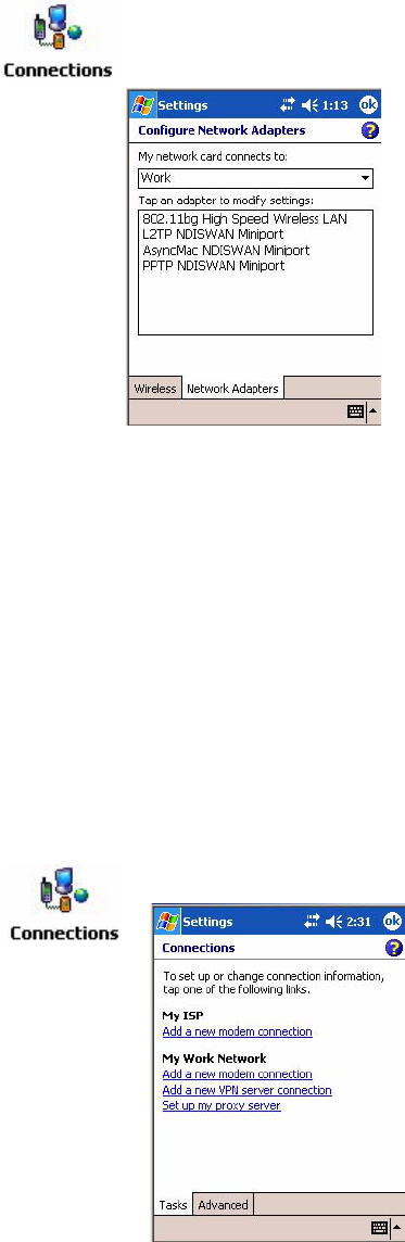
Tap Start > Settings > the Connections tab > the Connections icon > the
Advanced tab > Network Card > the Network Adapters tab to access the
network connections for this unit, then tap ok when finished.
1Tap Start > Settings > the Connections tab > the Connections icon.
Chapter 4 — Network Support
96 CN2B Mobile Computer User’s Manual
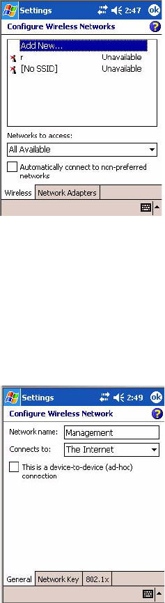
2Tap the Advanced tab > Network Card > the Wireless tab > Add New.
3Tap the General tab, then enter a network name. If the network was
detected, the network name is entered and cannot be changed.
From Connects to, select to what your network is to connect. If you
select “Work,” you can do a vpn connection or use proxy servers. If you
select “The Internet,” you can connect directly to the internet.
To connect to an ad-hoc connection, select This is a device-to-device
(ad-hoc) connection.
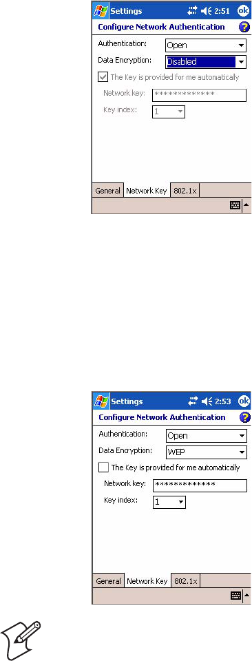
4Tap the Network Key tab, then do the following:
Chapter 4 — Network Support
CN2B Mobile Computer User’s Manual 97
To Disable Authentication
aSet Authentication to either “Open” if WEP keys are not required; or
“Shared” when WEP keys are required for association.
bSet Data Encryption to “Disabled.”
To Enable WEP Encryption
aSet Authentication to either “Open” if WEP keys are not required; or
“Shared” when WEP keys are required for association.
bSet Data Encryption to “WEP.”
cTo change the network key, clear The Key is provided for me auto-
matically box, then enter the new Network key and select the appro-
priate Key index.
Note: The following information applies when you have Enable
Microsoft’s Wireless Zero Config checked via the Wireless Network
applet (see page 194).
Chapter 4 — Network Support
98 CN2B Mobile Computer User’s Manual
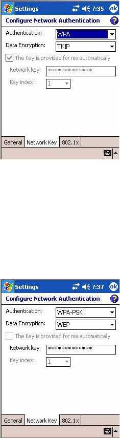
To Enable WPA Authentication
aSet Authentication to “WPA.” See page 195 for information about
WPA encryption.
bSet Data Encryption to “WEP” or “TKIP.” See page 195 for informa-
tion about WEP encryption and page 194 for TKIP encryption.
To Enable WPA Authentication Using a Preshared Key
aSet Authentication to “WPA-PSK.” See page 195 for information
about WPA encryption.
bSet Data Encryption to “WEP” or “TKIP.” See page 195 for informa-
tion about WEP encryption and page 194 for TKIP encryption.
cEnter the new Network key.
Chapter 4 — Network Support
CN2B Mobile Computer User’s Manual 99
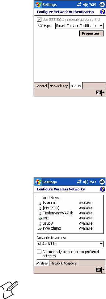
5Tap the 802.1x tab, select either “PEAP” or “Smart Card or Certificate”
for the EAP type, then tap Properties to adjust its settings.
6Tap ok to return to the Configure Wireless Network screen.
7From the Networks to access drop-down list, select “All Available,”
“Only access points,” or “Only computer-to-computer” depending on
the type of networks to which you connect.
To connect only to networks you have already configured, clear Auto-
matically connect to non-preferred networks.
Tap ok to close this screen.
Note: If you select to automatically connect to non-preferred networks,
your device detects new networks and provide you the opportunity to con-
figure them.

Chapter 4 — Network Support
100 CN2B Mobile Computer User’s Manual
AutoIP/DHCP
Automatic Private IP Addressing (AutoIP) is enabled by default in Win-
dows Mobile 2003. To remain compatible with other versions of Pocket
PC, this setting needs to be enabled. You can configure the registry settings
in HKEY_LOCAL_MACHINE\Comm\NETWLAN1\TcpIp to set the
required AutoIP/DHCP behavior.
AutoInterval, AutoMask, AutoSubnet, AutoIP, and AutoSeed are other
registry keys that can modify the behavior of AutoIP. You can find the
appropriate settings and behavior of each of these keys in Microsoft Help.
When a TCP/IP client cannot find a DHCP server, it generates an AutoIP
address from the 169.254.xxx.xxx block. The client then tries to check for a
DHCP server every 15 seconds and if a DHCP server is found, the client
drops the AutoIP address and uses the address from the DHCP server.
In the MSDN Windows CE documentation available out on the Microsoft
Developer Network web site (www.msdn.com), see “Automatic Client Con-
figuration” for more information on AutoIP.
To disable AutoIP, set the AutoCfg registry entry to “0.” If a DHCP server
cannot be found, instead of using AutoIP, the system will display the
“Unable to obtain a server assigned IP address” message.
Wide Area Networks
The CN2B Computer does not support wide area networks.
Note: If you try to disable AutoIP using a CAB file to set the registry value
for AutoIP, remember to set the EnableDHCP value to “1” to keep DHCP
enabled.
Note: For more attempts a DHCP client makes to get a DHCP address,
use the DhcpRetryDialogue and DhcpMaxRetry registry settings.
Note: Change the AutoInterval registry key value to make the client retry
more often to obtain a DHCP address.
Chapter 4 — Network Support
CN2B Mobile Computer User’s Manual 101
Remote Access (Modems)
You can set up connections to the Internet and corporate network at work
to browse the Internet or intranet, send and receive e-mail and instant mes-
sages, and synchronize information using ActiveSync. Connections can be
made using a wireless network.
Your CN2B Computer has two groups of connection settings: My ISP and
My Work Network. Use My ISP settings to connect to the Internet. Use
My Work Network settings to connect to any private network.
• My ISP: Once connected, you can send and receive e-mail messages by
using Inbox and view Web or WAP pages by using Pocket Internet
Explorer. The communication software for creating an ISP connection is
already installed on your CN2B Computer. Your service provider pro-
vides the software needed to install other services, such as paging and fax
services. If this is the method you want to use, see “Connecting to an
Internet Service Provider (ISP)” on page 101.
• My Work Network: Connect to the network at your company or organi-
zation where you work. Once connected, you can send and receive e-
mail messages by using Inbox, view Web or WAP pages by using Pocket
Internet Explorer, and synchronize with your desktop. If this is the
method you want to use, see “Connecting to Work” on page 104.
Connecting to an Internet Service Provider (ISP)
You can connect to your ISP, and use the connection to send and receive e-
mail messages and view Web or WAP pages.
Obtain your ISP dial-up access telephone number, user name, and pass-
word from your ISP. Some ISPs require information in front of the user
name, such as MSN/username.
To view additional information for any screen in the wizard or while
changing settings, tap the Help icon.
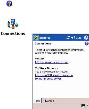
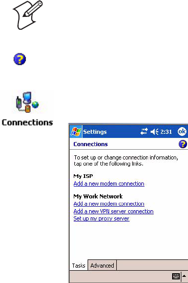
1Tap Start > Settings > the Connections tab > the Connections icon. In
My ISP, tap Add a new modem connection.
Chapter 4 — Network Support
102 CN2B Mobile Computer User’s Manual
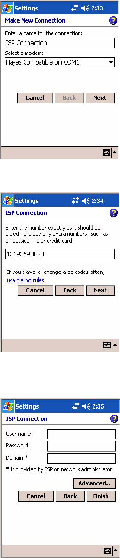
2Enter a name for the connection, such as “ISP Connection.”
If using an external modem connected to your CN2B Computer with a
cable, select “Hayes Compatible on COM1” from the Select a modem
list. Tap Next to continue.
3Enter the access phone number, then tap Next.
4Enter the user name, password, and domain (if provided by an ISP or
your network administrator), then tap Finish.
Chapter 4 — Network Support
CN2B Mobile Computer User’s Manual 103
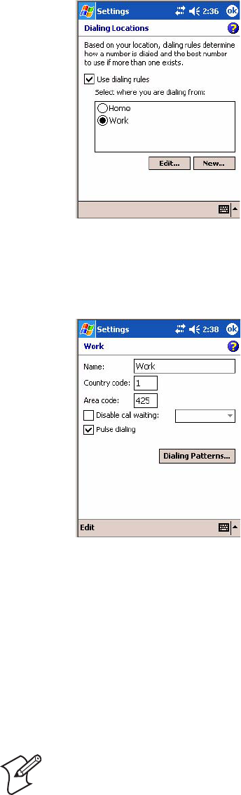
5Tap the Advanced tab from the Connections screen, then tap Select
Location to specify your current location. These settings apply to all con-
nections. Tap Use dialing rules, tap OK, then tap Edit to continue.
6Specify your current phone type. If your phone type is pulse dialing,
check the Pulse dialing box. If your type is tone dialing (as most phone
lines are), then clear the Pulse dialing box. Continue to tap ok to close
each page and return to the Settings page.
To start the connection, start using one of the following programs. Once
connected, you can:
• Send and receive e-mail messages by using Inbox. Before you can use
Inbox, you need to provide the information it needs to communicate
with the e-mail server.
• Visit Web and WAP pages by using Pocket Internet Explorer. For more
information, see “Pocket Internet Explorer” on page 71.
• Send and receive instant messages with MSN Messenger. For more
information, see “MSN Messenger” on page 65.
Note: To change modem connection settings in My ISP, tap Manage
existing connections. Select the desired modem connection, tap Settings,
and follow the instructions on the screen.
Chapter 4 — Network Support
104 CN2B Mobile Computer User’s Manual
Connecting to Work
If you have access to a network at work, you can send e-mail messages, view
intranet pages, synchronize your CN2B Computer, and possibly access the
Internet. You can connect to work by creating a modem connection via a
RAS (Remote Access Server) account. Before you can create this modem
connection, your network administrator needs to set up a RAS account for
you. Your network administrator may also give you Virtual Private Net-
work (VPN) settings.
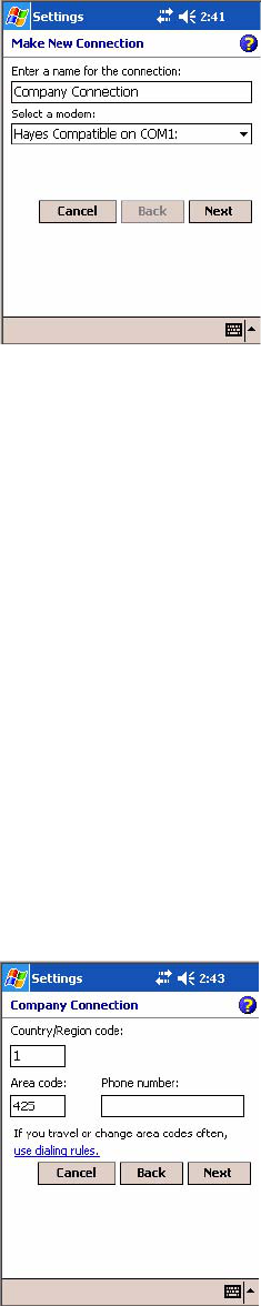
2Enter a name for the connection, such as “Company Connection.” In
the Select a modem list, select your modem type, then tap Next to con-
tinue. If your modem type does not appear, try reinserting your CN2B
Computer into your modem dock.
• If using an external modem connected to your CN2B Computer with
a cable, select “Hayes Compatible on COM1.”
• If using any type of external modem, select the modem by name. If a
listing does not exist for your external modem, select “Hayes Compat-
ible on COM1.”
• Wireless connections can be made via a mobile phone network or
GPRS. If using a mobile phone network to connect, select “Cellular
Line.” If using GPRS, tap “Cellular Line (GPRS).”
Note: To change modem connection settings in My Work Network, tap
Manage existing connections. Select the desired modem connection, tap
Edit, and follow the instructions on the screen.
To view additional information for any screen in the wizard or while
changing settings, tap the Help icon.
1Tap Start > Settings > the Connections tab > the Connections icon. In
My ISP, tap Add a new modem connection.
Chapter 4 — Network Support
CN2B Mobile Computer User’s Manual 105
3Enter the access phone number, using some of the following guidelines.
If you know part of the phone number changes frequently as you travel,
create dialing rules to avoid creating numerous modem connections for
the same phone number. For more information, tap Use Dialing Rules.
• Enter the phone number exactly as you want it dialed. For example, if
you call from a business complex or hotel that requires a nine before
dialing out, enter “9” in front of the phone number.
• Enter the APN provided by your mobile phone service provider.
• When using dialing rules, phone numbers are entered differently. To
use additional numbers, such as a “9” to dial from an office complex
or hotel, you must use additional dialing rules or change dialing pat-
terns. See “Create Dialing Rules” via your online help for information.
aIn the Country/Region box, enter the appropriate code when dialing
internationally. For more information, contact an operator at your
local phone company.
bIn the Area code box, enter the area code, if needed.
cEnter the main phone number, then tap Next to continue.
Chapter 4 — Network Support
106 CN2B Mobile Computer User’s Manual
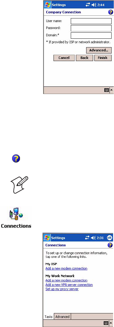
4Enter the user name, password, and domain (if provided by an ISP or
your network administrator). If a domain name was not provided, try
the connection without entering a domain name, then tap Finish.
Creating a VPN Server Connection to Work
A VPN connection helps you to securely connect to servers, such as a cor-
porate network, via the Internet. Ask your network administrator for the
user name, password, domain name, TCP/IP settings, and host name or IP
address of the VPN server.
To view additional information for any screen in the wizard or while
changing settings, tap the Help icon.
Note: To change existing settings in My Work Network, tap Manage
existing connections > the VPN tab. Select the desired VPN connection,
tap Settings, and follow the instructions on the screen.
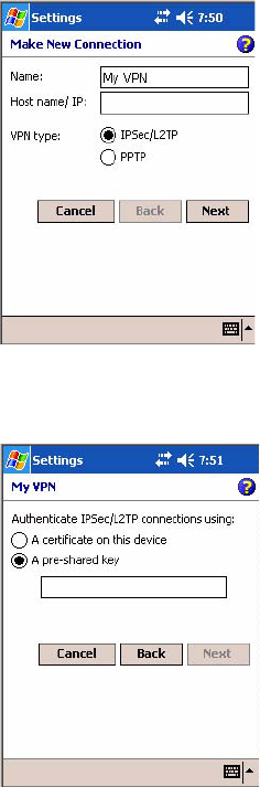
1Tap Start > Settings > the Connections tab > the Connections icon.
Tap Add a new VPN server connection beneath My Work Network to
initiate this procedure.
Chapter 4 — Network Support
CN2B Mobile Computer User’s Manual 107
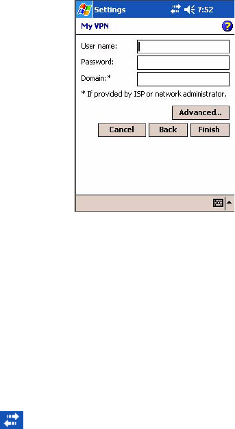
2In Name, enter a name for the connection, such as a company’s name.
In Host name/ IP, enter the VPN server name or IP address.
Next to VPN type, select the type of authentication to use with your
device: “IPSec/L2TP” or “PPTP.” If you are not sure which option to
choose, ask your network administrator. Tap Next to continue.
3Select the type of authentication. If you select A pre-shared key, enter
the key provided by your network administrator.
Chapter 4 — Network Support
108 CN2B Mobile Computer User’s Manual
4Enter your user name, password, and domain name as provided by your
ISP or network administrator. If a domain name was not provided, try
the connection without entering a domain name.
5You should not need to change any Advanced settings. Instances where
to change advanced settings include the server to which you are connect-
ing does not use dynamically-assigned addresses, and you need to enter
your TCP/IP settings; or to change server DNS or WINS settings.
To change advanced settings, tap Advanced. Otherwise, tap Finish.
Insert necessary equipment, such as a network card, into the device, and
use a desired program to automatically begin connecting.
Ending a Connection
• When connected via cable or cradle, detach your device.
• When connected via Infrared, move away from other computers.
• When connected via a wireless network, switch off the connection.
Management
Use the following tool and information to configure and manage your net-
work. You can also contact your Intermec representative for support.
SmartSystems™ Foundation Console (www.intermec.com/SmartSystems)
This tool, available as a free download from Intermec, includes a manage-
ment console that provides a default method to configure and manage
Intermec devices “out-of-the-box,” without the purchase of additional soft-
ware licenses. This is for anyone who must configure and deploy multiple
devices or manage multiple licenses.
Use the Intermec Settings applet to gather, view, and update device config-
uration settings within the SmartSystems Foundation. Information about
• When connected via modem or VPN, tap the Connectivity icon on the
navigation bar, then tap Disconnect.
Chapter 4 — Network Support
CN2B Mobile Computer User’s Manual 109
the settings you can configure with the Intermec Settings applet is in the
Intermec Computer Command Reference Manual (P/N: 073529) available
online at www.intermec.com.
Information about the SmartSystems Foundation is available as an online
help within the SmartSystems Console application. Select SmartSystems >
Help in the console to access the manual.
See the Data Collection Resource Kit in the Intermec Developer Library
(IDL) for information about data collection functions. The IDL is available
as a download from the Intermec web site at www.intermec.com/idl. Con-
tact your Intermec representative for more information.
SNMP Configuration on the Mobile Computer
In short, SNMP is an application-layer protocol that uses the exchange of
management information between network devices. The CN2B Computer
is such an SNMP-enabled device. Use SNMP to control and configure the
CN2B Computer anywhere on an SNMP-enabled network.
The CN2B Computer supports four proprietary Management Information
Bases (MIBs) and Intermec Technologies provides SNMP support for
MIB-II through seven read-only MIB-II (RFC1213-MIB) Object Identifi-
ers (OIDs).
Management Information Base
The Management Information Base is a database that contains information
about the elements to be managed. The information identifies the manage-
ment element and specifies its type and access mode (Read-Only, Read-
Write). MIBs are written in ASN.1 (Abstract Syntax Notation.1) — a
machine independent data definition language. Note: Elements to manage
are represented by objects. The MIB is a structured collection of such objects.
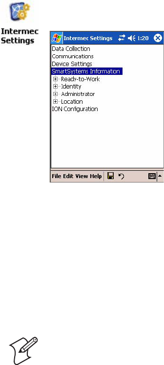
Tap Start > Settings > the System tab > the Intermec Settings icon, then
tap to expand the SmartSystems Information option.
Note: You can only query these seven OIDs through an SNMP manage-
ment station.

Chapter 4 — Network Support
110 CN2B Mobile Computer User’s Manual
You will find the following MIB files either in the CN2B Management
Tools or on the web via www.intermec.com:
•INTERMEC.MIB
Defines the root of the Intermec MIB tree.
•ITCADC.MIB
Defines objects for Automated Data Collection (ADC).
•ITCSNMP.MIB
Defines objects for Intermec SNMP parameters and security methods,
such as an SNMP security IP address.
•ITCTERMINAL.MIB
Defines objects for parameters, such as key clicks.
Object Identifiers
Each object has a unique identifier called an OID, which consist of a
sequence of integer values represented in dot notation. Objects are stored in
a tree structure and OIDs are assigned based on the position of the object
in the tree. For example, the internet OID is equal to 1.3.6.1. Seven MIB
OIDs are shown in the following table:
MIB Object Identifiers
MIB-II Item OID Group or Table Description
ifNumber 1.3.6.1.2.1.2.1.0 Interfaces Group Indicates the number of adapters
present in the system. For the
CN2B Computer, if one adapter
is present in the system, then
ifNumber = 1 and ifIndex = 1.
ifIndex 1.3.6.1.2.1.2.2.1.1.ifIndex Interfaces Table (ifTable) A unique value for each interface.
The value ranges between 1 and
the value of ifNumber.
ifDescr 1.3.6.1.2.1.2.2.1.2.ifIndex Interfaces Table (ifTable) A textual string containing infor-
mation about the interface.
ifType 1.3.6.1.2.1.2.2.1.3.ifIndex Interfaces Table (ifTable) An integer containing informa-
tion about the type of the inter-
face. It is equal to 1 for Other.
ipAdEntAddr 1.3.6.1.2.1.4.20.1.1.IpAddress IP address Table
(ipAddrTable) The IP address to which this
entry’s addressing information
pertains (same as CN2B IP
address), where IP Address is the
valid non-zero IP address of the
CN2B Computer.
ipAdEntIfIndex 1.3.6.1.2.1.4.20.1.2.IpAddress IP address Table
(ipAddrTable) Index value that uniquely identi-
fies the interface that this entry is
applicable (same as ifIndex).
ipAdEntNetMask 1.3.6.1.2.1.4.20.1.3.IpAddress IP address Table
(ipAddrTable) The subnet mask associated with
the IP address of this entry (same
as Subnet Mask).
Chapter 4 — Network Support
CN2B Mobile Computer User’s Manual 111
Configuring with SNMP
The community string allows an SNMP manager to manage the CN2B
Computer with a specified privilege level. The default read-only commu-
nity string is “public” and “private” is the default read/write community
string. See the specific configuration parameter to find its OID. To config-
ure the CN2B Computers using SNMP:
1Configure CN2B Computers for RF or Ethernet communications.
2Determine the OID (Object Identifier) for the parameter to change. The
Intermec base OID is 1.3.6.1.4.1.1963.
3Use your SNMP management station to get and set variables that are
defined in the Intermec MIBs. You can set the traps, identification, or
security configuration parameters for SNMP. See Appendix A, “Config-
urable Settings” to learn more about these parameters.
Chapter 4 — Network Support
112 CN2B Mobile Computer User’s Manual

CN2B Mobile Computer User’s Manual 113
5Printer Support
The CN2B Mobile Computer works with the following printers from
Intermec Technologies. Contact an Intermec representative for informa-
tion about these printers.
•6820 Portable or Fixed Mount 80-Column Printer
•PB20 2” Belt-Mount Printer
with a Bluetooth compatible module from Socket Communications
•PB40 4” Belt-Mount Printer
with a Bluetooth compatible module from Socket Communications
•PB42 4” Printer
Chapter 5 — Printer Support
114 CN2B Mobile Computer User’s Manual
Printing ASCII
The following methods for printing using Pocket PC at this time is as fol-
lows:
• Add port drivers to print ASCII directly to the port.
• Use LinePrinter ActiveX Control from the Printing Resource Kit via the
Intermec Developer Library (IDL) available as a download from the
Intermec webs site at www.intermec.com. Contact your Intermec repre-
sentative for more information.
• Via wireless printing - see the Wireless Printing Development Guide for
more information.
Directly to a Port
Printing directly to the port sends RAW data to the printer. The format of
this data depends upon your application and the printer capabilities.
You must understand the printer commands available for your specific
printer. Generally, applications just send raw ASCII text to the printer.
Since you are sending data to the printer from your application directly to
the port you are in complete control of the printers operations. This allows
you to do line printing (print one line at a time) rather than the page format
printing offered by the GDI approach. It is also much faster since data does
not have to be converted from one graphics format to the other (display to
printer). Most Intermec printers use Epson Escape Sequences to control
print format operations.
These commands are available in documentation you receive with your
printers or from technical support. Win32 APIs are required to print
directly to the port.
Directly to a Generic Serial Port
To print directly to a generic serial port printer (non-Intermec printers):
• Use CreateFile() to open ports — COM1 can open on most devices.
• Use WriteFile() to send data directly to the printer.
• Use CloseHandle() when you are finished printing to close the port.
NPCP Printer Driver
The NPCP printer communications driver (NPCPPORT.DLL) is a
Stream Device Driver built into the operating system. The driver supports
only NPCP communications to and from the 6820 printers over a selected
serial port.
All applications use WIN32 API functions to access the drivers. Basic oper-
ations are easily implemented by applications through the CreateFile(),
Chapter 5 — Printer Support
CN2B Mobile Computer User’s Manual 115
WriteFile(), ReadFile(), DeviceIOControl(), and CloseHandle() Win32
APIs.
Operations to upgrade printer modules, perform printer diagnostics, and
get printer configuration are performed largely via DeviceIOControl()
functions.
About NPCP
NPCP (Norand® Portable Communications Protocol) is a proprietary pro-
tocol that provides session, network, and datalink services for Intermec
mobile computers in the Intermec LAN environment used with printers
and data communications.
NPCP Driver Installation and Removal
Use LPT9: for the NPCP printer device and COM1 for the last parameter.
COM1 is the connection available via the CN2B Computer.
Applications use the RegisterDevice() function to install the driver. Dereg-
isterDevice() uninstalls the device driver and frees memory space when the
driver is not required. Use the HANDLE returned by RegisterDevice() as
the parameter to DeregisterDevice().
Use the RegisterDevice() function call as demonstrated below. Specify the
full path name to the driver starting at the root for the RegisterDevice()
function to work properly. The last parameter to RegisterDevice() is a
DWORD that represents the name of the port for the NPCP stream driver
to use. Build this parameter on the stack if it is not to be paged out during
the call. The first parameter “LPT” (Device Name) and the second parame-
ter “9” (index), indicate the name of the registered device, such as LPT9.
This is used in the CreateFile() function call.
Install()
{
HANDLE hDevice;
TCHAR port[6];
port[0] = TCHAR(‘C’);
port[1] = TCHAR(‘O’);
port[2] = TCHAR(‘M’);
port[3] = TCHAR(‘1’);
port[4] = TCHAR(‘:’);
port[5] = TCHAR(0);
hDevice = RegisterDevice ( (TEXT(”LPT”), 9,
TEXT(“\\STORAGE CARD\\WINDOWS\\NPCPPORT.dll”), (DWORD)port);
}
Opening the NPCP Driver
The application opens the NPCP driver by using the CreateFile() function.
The call can be implemented as follows. The first parameter “LPT9:” must
reflect the device name and index used in the RegisterDevice() function call
and will fail for any of the following reasons:
Chapter 5 — Printer Support
116 CN2B Mobile Computer User’s Manual
hFile = CreateFile(_T(”LPT9:”), GENERIC_WRITE |
GENERIC_READ, 0, NULL, OPEN_ALWAYS, FILE_ATTRIBUTE_NORMAL,
NULL);
• The port associated with the device during RegisterDevice() is in use.
• The NPCP device is already open.
• The share mode is not set to zero. The device cannot be shared.
• Access permissions are not set to GENERIC_WRITE |
GENERIC_READ. Both modes must be specified.
Closing the NPCP Driver
Using the CloseHandle() (hFile) function closes the NPCP driver. Where
hFile is the handle returned by the CreateFile() function call.
• TRUE = the device is successfully closed.
• FALSE = an attempt to close NULL HANDLE or an already closed
device.
Reading from the NPCP Driver
Reading of the NPCP printers is not supported since all responses from the
printer are the result of commands sent to the printer. DeviceIoControl()
functions are provided where data is to be received from the printer.
Writing to the NPCP Driver
All Print data can be sent to the printer using the WriteFile() function. The
print data written to the driver must contain the proper printer commands
for formatting. If the function returns FALSE, the NPCP error may be
retrieved using IOCTL_NPCP_ERROR. See the description on the next
page.
NPCP Driver I/O Controls
An application uses the DeviceIoControl() function to specify an printer
operation to perform. Certain I/O controls are required to bind and close
communication sessions with the printer, and must be completed before
any other commands to the driver can execute properly.
The function returns TRUE to indicate the device successfully completed
its specified I/O control operation, otherwise it returns FALSE. The follow-
ing I/O control codes are defined:
#define IOCTL_NPCP_CANCEL
CTL_CODE(FILE_DEVICE_SERIAL_PORT,0x400,METHOD_BUFFERED,FILE_ANY_ACCESS)
#define IOCTL_NPCP_BIND
CTL_CODE(FILE_DEVICE_SERIAL_PORT,0x401,METHOD_BUFFERED,FILE_ANY_ACCESS)
#define IOCTL_NPCP_CLOSE
CTL_CODE(FILE_DEVICE_SERIAL_PORT,0x402,METHOD_BUFFERED,FILE_ANY_ACCESS)
Chapter 5 — Printer Support
CN2B Mobile Computer User’s Manual 117
#define IOCTL_NPCP_ERROR
CTL_CODE(FILE_DEVICE_SERIAL_PORT,0x403,METHOD_BUFFERED,FILE_ANY_ACCESS)
#define IOCTL_NPCP_FLUSH
CTL_CODE(FILE_DEVICE_SERIAL_PORT,0x404,METHOD_BUFFERED,FILE_ANY_ACCESS)
#define IOCTL_NPCP_IOCTL
CTL_CODE(FILE_DEVICE_SERIAL_PORT,0x405,METHOD_BUFFERED,FILE_ANY_ACCESS)
#define IOCTL_NPCP_PRTVER
CTL_CODE(FILE_DEVICE_SERIAL_PORT,0x406,METHOD_BUFFERED,FILE_ANY_ACCESS)
•IOCTL_NPCP_CANCEL
This cancels all printing at the printer. It flushes the printer buffers and
re initializes the printer to its default state. No parameters are required.
•IOCTL_NPCP_BIND
This command is required before any data is sent or received by the
printer. Once the driver is opened, the application must bind the com-
munications session with the printer before any data can be sent or
received by the printer. If an error occurs during the bind, the applica-
tion may use IOCTL_NPCP_ERROR to get the current extended error
code. No parameters are required.
•IOCTL_NPCP_CLOSE
This command closes the current session with the printer. This function
always returns TRUE. No parameters are required.
•IOCTL_NPCP_ERROR
This command returns the extended NPCP error code in PL/N format.
The word returned will contain the PL/N compatible error code in the
low byte and completion flags in the high byte. If the frame that
returned an error was not received correctly by the printer the
FRAME_NOT_ACKED bit is set in the high byte. This operation
always returns TRUE. An output buffer of at least two bytes is required.
See “NPCP Error Codes” on page 118.
•IOCTL_NPCP_FLUSH
This command allows the application to poll the printer for errors while
the report is completing the print process at the printer. If an error
occurs during the polling process, the operation will return FALSE and
the application can get the extended error code by using
IOCTL_NPCP_ERROR. No parameters are required.
NPCP Printer Communications
All NPCP printer communications should be based on the following flow:
1Use CreateFile(); to open the printer driver.
2Use IOCTL_NPCP_BIND to bind a session with the printer;
IOCTL_NPCP_ERROR to check for errors on the bind to ensure suc-
cess; and IOCTL_NPCP_CANCEL to cancel any outstanding print
jobs.
Chapter 5 — Printer Support
118 CN2B Mobile Computer User’s Manual
3Use IOCTL_NPCP_FLUSH to poll the printer to free up printer buffer
resources. Use IOCTL_NPCP_FLUSH to poll the printer’s status. If an
error is reported by the IOCTL, then use IOCTL_NPCP_ERROR to
get the error and determine the correct recovery procedure.
4Use WriteFile(); to write your data to the printer. Check for errors and
that all data were written. Use IOCTL_NPCP_ERROR to get the
extended error. If the error is critical in nature, use
IOCTL_NPCP_CLOSE, followed by CloseFile(), to end the communi-
cations session. Start a new session, beginning with step 1 to ensure
proper printing. For noncritical errors display the error and retry the
operation.
5After all data is sent to the printer, ensure that the printer continues to
print the report properly by polling the printer’s status. Use
IOCTL_NPCP_FLUSH to poll the printer’s status. If an error is
reported by the IOCTL, then use IOCTL_NPCP_ERROR to get the
error and determine the correct recovery procedure.
Sample Code
See sample code in the “\CN2B Dev Tools\Installable Drivers\Port Driv-
ers\Npcp\NPCPPrint\” directory for more details on printing, printer com-
munications and error code handling.
NPCP Error Codes
Call the IOCTL_NPCP_ERROR I/O control function to receive PL/N
compatible error codes. Applications must decide how to act upon the data
returned.
// Definition of NPCP communications Errors and Printer Errors
#define PNRDY (BYTE)102 // link not ready error
#define RXTMO (BYTE)104 // link no receive error
#define TXTMO (BYTE)106 // link no transmit error
#define BADADR (BYTE)111 // frame address error
#define GAPERR (BYTE)112 // link gap error (timeout) in receive data
#define LSRPE (BYTE)113 // frame parity error on length field
#define IFTS (BYTE)120 // session layer - invalid frame this state
#define NS_NE_VR (BYTE)121 // session layer sequence error
#define NR_NE_VS (BYTE)122 // session layer sequence error
#define MAC_CRCERR (BYTE)124 // MAC CRC error
#define RLENERR (BYTE)123 // MAC too much data received
#define FRMERR (BYTE)200 // Frame Reject
#define FRMERR_IF (BYTE)201 // Frame Reject - Invalid Frame
#define FRMERR_NR (BYTE)202 // Frame Reject - NR Mismatch
#define FRMERR_NS (BYTE)203 // Frame Reject - NS Mismatch
#define NDMERR (BYTE)204 // Normal Disconnect mode error
#define BINDERR (BYTE)210 // bind error
#define IPLDUR (BYTE)221 // invalid presentation layer response
#define HEADJAM (BYTE)222 // printer head jam
#define PAPEROUT (BYTE)223 // printer paper out
#define LOWVOLTS (BYTE)224 // printer low voltage
#define HIVOLTS (BYTE)225 // printer over voltage
#define LOWBAT (BYTE)226 // printer low battery
Chapter 5 — Printer Support
CN2B Mobile Computer User’s Manual 119
#define COVEROFF (BYTE)227 // printer cover off error
#define HEADFAULT (BYTE)228 // printer head short or driver short error
#define PFFAULT (BYTE)229 // paper feed motor fault.
#define FRAME_NOT_ACKED 0x8000 // frame was not received by printer and need to
be resent.
O’Neil Printer Driver
The DTR printer communications driver is a Stream Device Driver named
ONEIL.DLL.
All applications use WIN32 API functions to access drivers. Basic opera-
tions are easily implemented by applications through the CreateFile(),
WriteFile(), DeviceIOControl() and CloseHandle() Win32 APIs.
The driver supports communications to PB20, PB40, and PB42 printers
over a selected serial port.
DTR Driver Installation and Removal
Your application must install the device driver by using the RegisterDe-
vice() function. The driver name is ONEIL.DLL. We recommend that you
use “DTR” for the Device Name parameter, “1” for the Device Driver
index parameter, and use any of the following strings for the last parameter:
• NULL (==0) Defaults to COM1 @ 9600
• “COM1” only COM port specified defaults to 9600
• “COM1:9600” sets to COM port and specified bit rate
• “COM1:19200” sets to COM port and specified bit rate
Use the HANDLE returned by RegisterDevice() as the parameter to Dereg-
isterDevice(). The correct usage of the RegisterDevice() function call is
demonstrated below. You may use DeregisterDevice() to uninstall the
driver.
Install()
{
HANDLE hDevice;
TCHAR port[6];
port[0] = TCHAR(‘C’);
port[1] = TCHAR(‘O’);
port[2] = TCHAR(‘M’);
port[3] = TCHAR(‘1’);
port[4] = TCHAR(‘:’);
port[5] = TCHAR(0);
hDevice = RegisterDevice ( (TEXT(”DTR”), 1, TEXT(”\\WINDOWS\\ONEIL.DLL”),
(DWORD)port);
}
Chapter 5 — Printer Support
120 CN2B Mobile Computer User’s Manual
Opening the DTR Driver
The application opens the DTR driver by using the CreateFile() function.
The call can be implemented as follows:
hFile = CreateFile(_T(”DTR1:”), GENERIC_WRITE, 0, NULL,
OPEN_ALWAYS, FILE_ATTRIBUTE_NORMAL, NULL);
The first parameter “DTR1:” must reflect the device name and index used
in the RegisterDevice() function call.
The function call will fail for any of the following reasons:
• The port associated with the device during RegisterDevice() is currently
in use.
• The DTR device is already open.
• The share mode is not set to zero. The device cannot be shared.
• Access permissions are not set to GENERIC_WRITE.
Closing the DTR Driver
Using the CloseHandle() (hFile) function closes the DTR driver. Where
hFile is the handle returned by the CreateFile() function call.
• TRUE indicates the device is successfully closed.
• FALSE indicates an attempt to close a NULL HANDLE or an already
closed device.
Writing to the DTR Driver
You can use the WriteFile() function to send all Print data to the printer.
The print data being written must contain the proper formatting printer
commands.
DTR Printer Communications
All DTR printer communications should be based on the following flow:
1Use CreateFile() to open the printer driver.
2Use WriteFile() to write your data to the printer. Check for errors and
that all data were written.
3Use CloseHandle() to close the driver.

CN2B Mobile Computer User’s Manual 121
6Scanner Support
The CN2B Mobile Computer is available with linear imaging technologies,
such as the APS Linear Imager, which includes the EV10 Scan Engine.
The APS Imager reads 1D symbologies and PDF417 bar codes. Linear
imaging using Vista Scanning technologies reads low-contrast bar codes,
laminated bar codes, and bar codes displayed on CRT or TRT displays.
This imaging uses harmless LEDs for illumination and does not require any
warning labels. Vista Scanning is more reliable than lasers as it is a com-
pletely solid state with no moving parts or oscillating mirrors.
An ImageDemo application shows the more common features of the
CN2B Computer imager. See the ImageDemo User’s Guide for information.

Chapter 6 — Scanner Support
122 CN2B Mobile Computer User’s Manual
Scanner Control and Data Transfer
The Data Server and associated software provide several ways to manipulate
scanner control and data transfer between the scanner subsystem and user
applications:
•Automatic Data Collection COM Interfaces:
These COM interfaces allow user applications to receive bar code data,
and configure and control the bar code reader engine.
•ITCAxBarCodeReaderControl functions:
These ActiveX controls allow user applications to collect bar code data
from the scanner, to configure the scanner, and to configure audio and
visual notification when data arrives.
•ITCAxReaderCommand functions:
Use these ActiveX controls to modify and retrieve configuration infor-
mation using the reader interface commands.
•Scanning EasySet bar code labels:
You can use the EasySet bar code creation software from Intermec Tech-
nologies Corporation to print configuration labels. Scan the labels to
change the scanner configuration and data transfer settings.
Use the Intermec EasySet software to print configuration labels you can
scan to change your configuration settings. For more information, see
the EasySet online help. EasySet is available from the Intermec Data
Capture web site.
For more information, see the Data Collection Resource Kit in the Inter-
mec Developer Library (IDL), which is available as a download from the
Intermec web site at www.intermec.com. Contact your Intermec represen-
tative for more information.
Data Collection Configuration
Note: To use the methods described below, enable Data Collection func-
tionality on the CN2B Computer using the bootloader configuration
menu.
You can configure scanner settings for the CN2B Computer via the Inter-
mec Settings applet. From the CN2B Computer, tap Start > Settings > the
System tab > the Intermec Settings icon. See the Intermec Computer Com-
mand Reference Manual (P/N: 073529) for information about the settings
you can configure with this applet. This online manual is available from the
Intermec web site at www.intermec.com.
Chapter 6 — Scanner Support
CN2B Mobile Computer User’s Manual 123
Internal Scanners
The Intermec Internal Scanner feature allows Automatic Data Collection
(ADC) by accepting data from the COM1 port and wedging it into the
keyboard interface. You can enable or disable this feature from the Today
screen on the CN2B Computer.
Do the following before you configure your internal scanner from the
Intermec Settings applet. Information about the settings you can configure
with this applet is described in the Intermec Computer Command Reference
Manual. The online manual is available from the Intermec web site at
www.intermec.com.
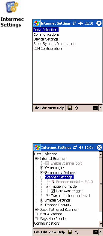
2Tap the Data Collection option, then tap (+) to expand Internal Scan-
ner. This sample screen is for the EV10 scanner model.
1From the CN2B Computer, tap Start > Settings > the System tab > the
Intermec Settings icon.
Chapter 6 — Scanner Support
124 CN2B Mobile Computer User’s Manual
Linear Imager Settings
Depending on what is selected as the scanner model, image settings, decode
security, and virtual wedge are configured from the Intermec Settings
applet. See the the Intermec Computer Command Reference Manual, avail-
able from the Intermec web site at www.intermec.com, for more informa-
tion about each enabled option.
Internal Scanner Supported Symbologies
The EV10 Scanner supports these symbologies:
Code 39, UPC/EAN, Code 128, Interleaved 2 of 5, Code 93, Codabar,
Standard 2 of 5, MSI, Plessey, Code 11, Matrix 2 of 5, Telepen, RSS,
Vest Code 39, ISBT 128, Code 93i
The EV10 also supports the following stacked symbologies:
PDF 417, Micro PDF, Macro PDF, Codablock, RSS