Intermec Technologies BTS080-2 6820 Printer User Manual legal
Intermec Technologies Corporation 6820 Printer legal
UserManual.wiki
>
Intermec Technologies
>
BTS080 2 User Manual
Users manual
Navigation menu
Upload a User Manual
Namespaces
Wiki Guide
HTML
PDF
Info
Views
User Manual
Discussion / Help
Navigation


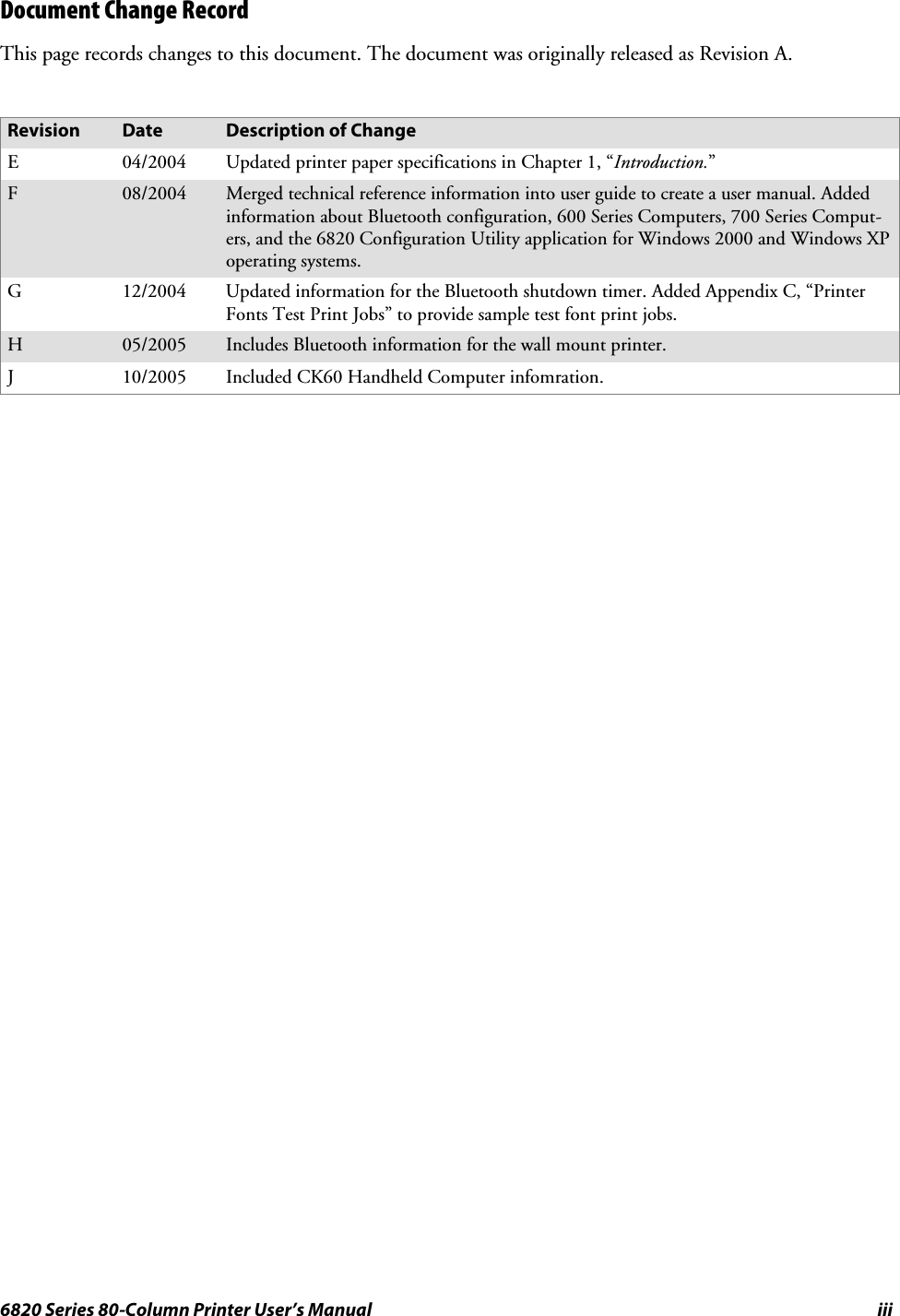

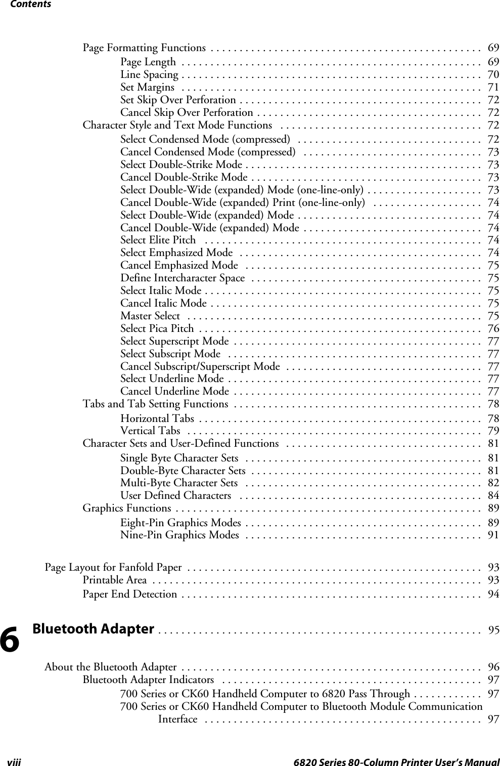


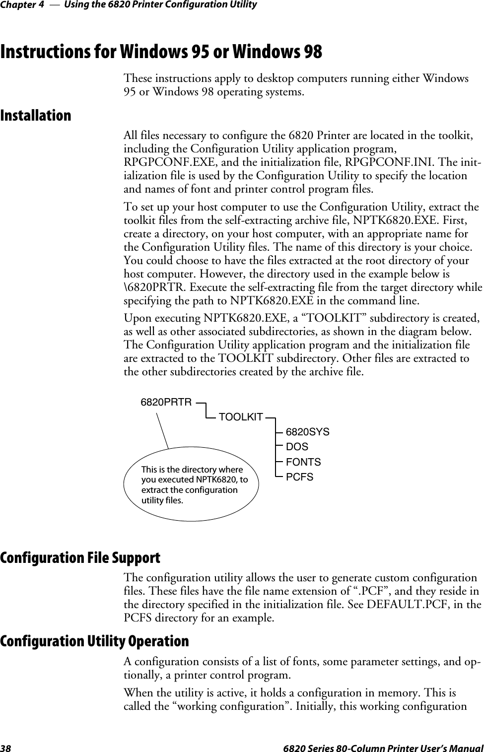

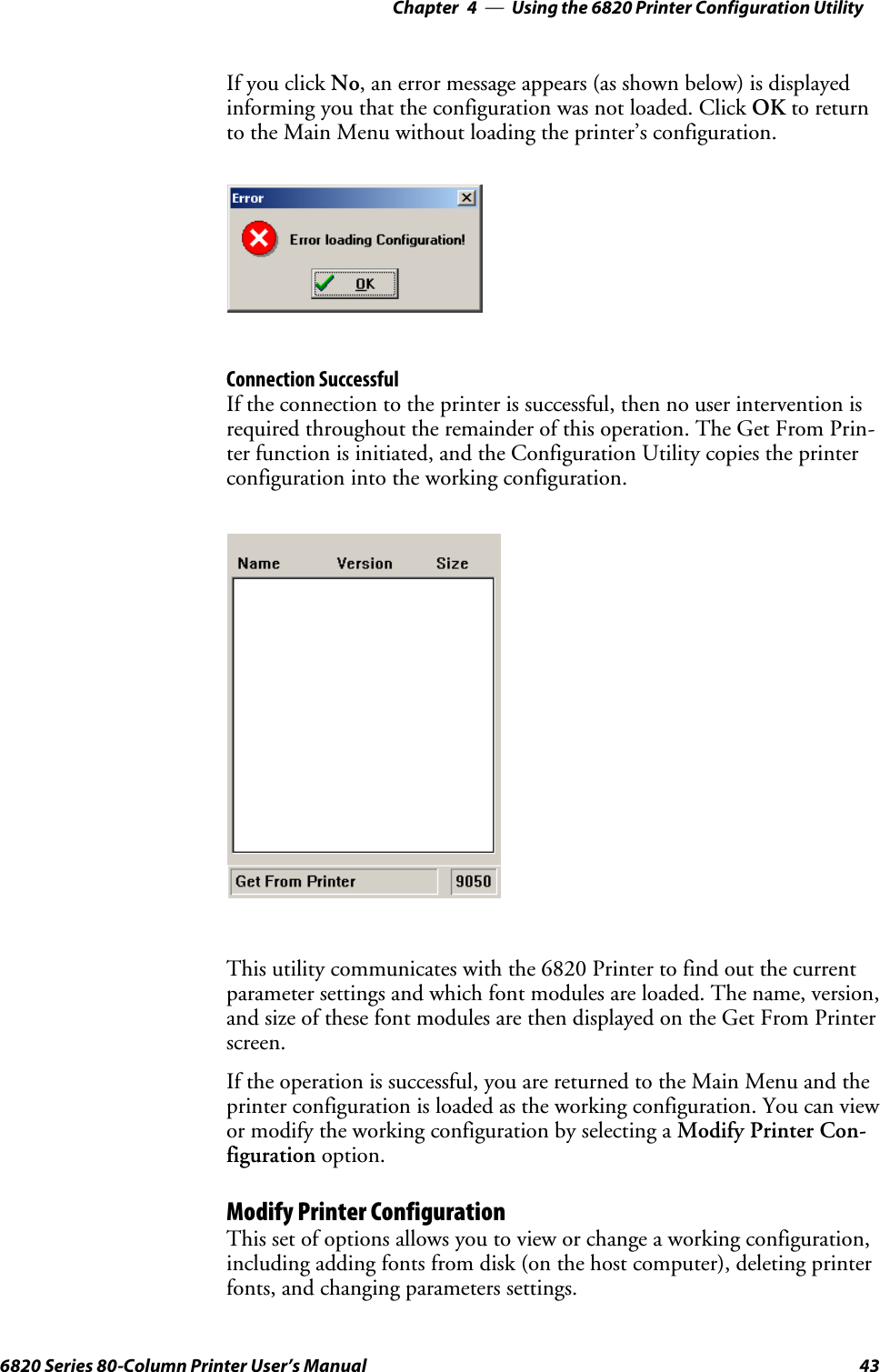
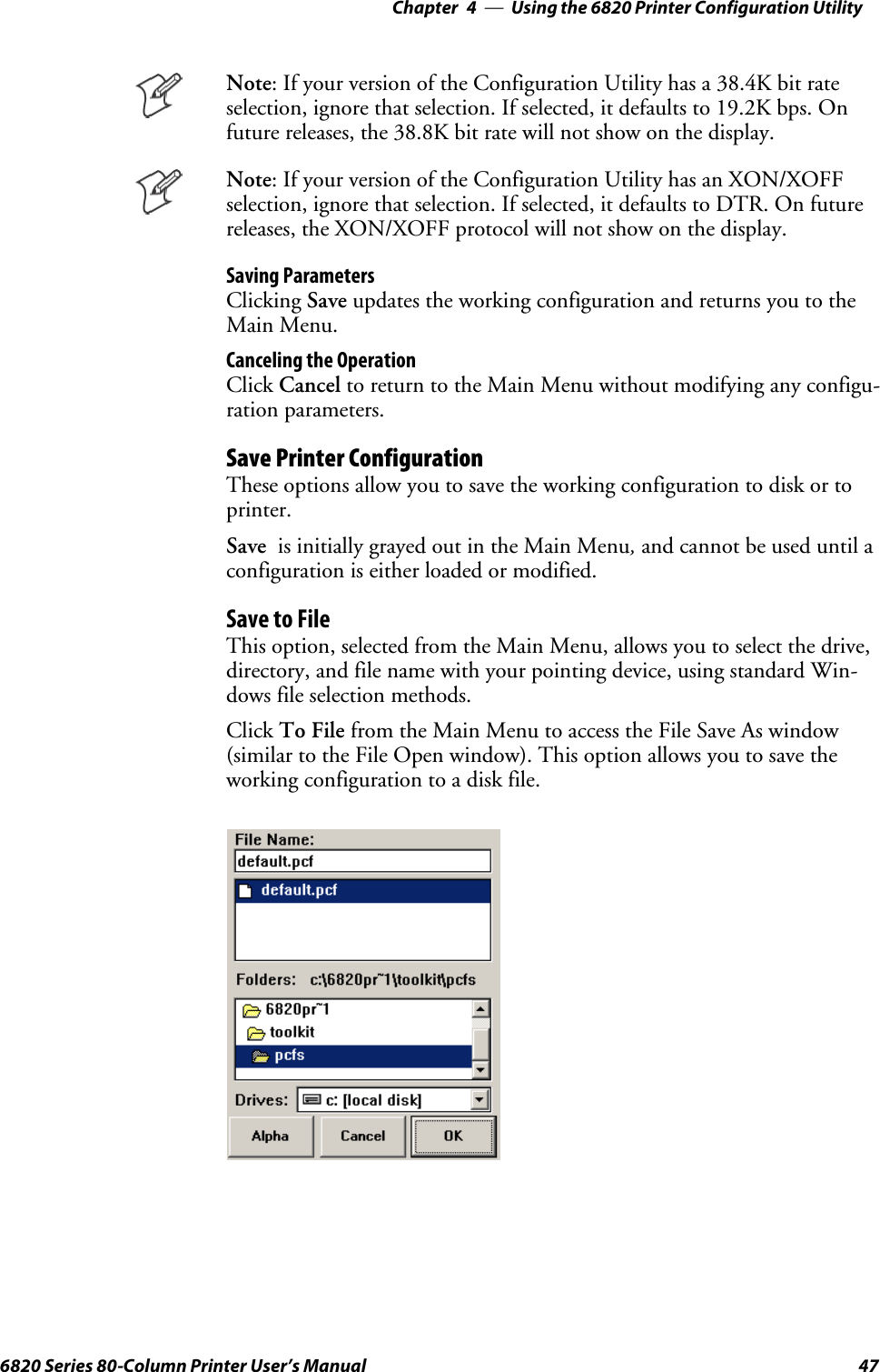
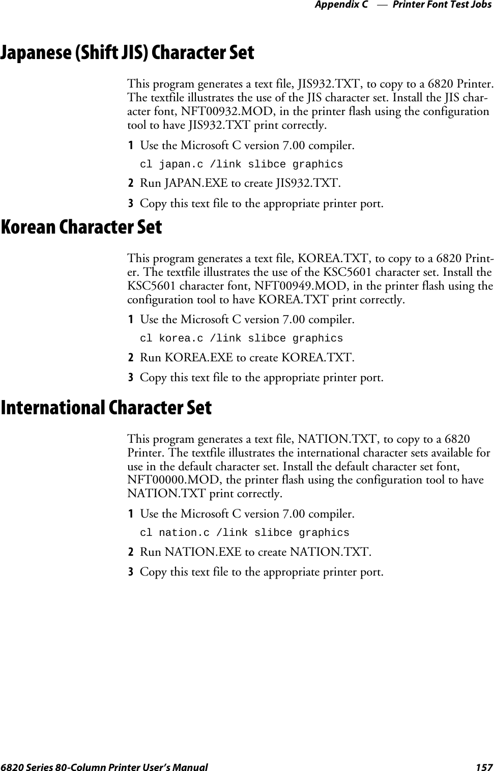
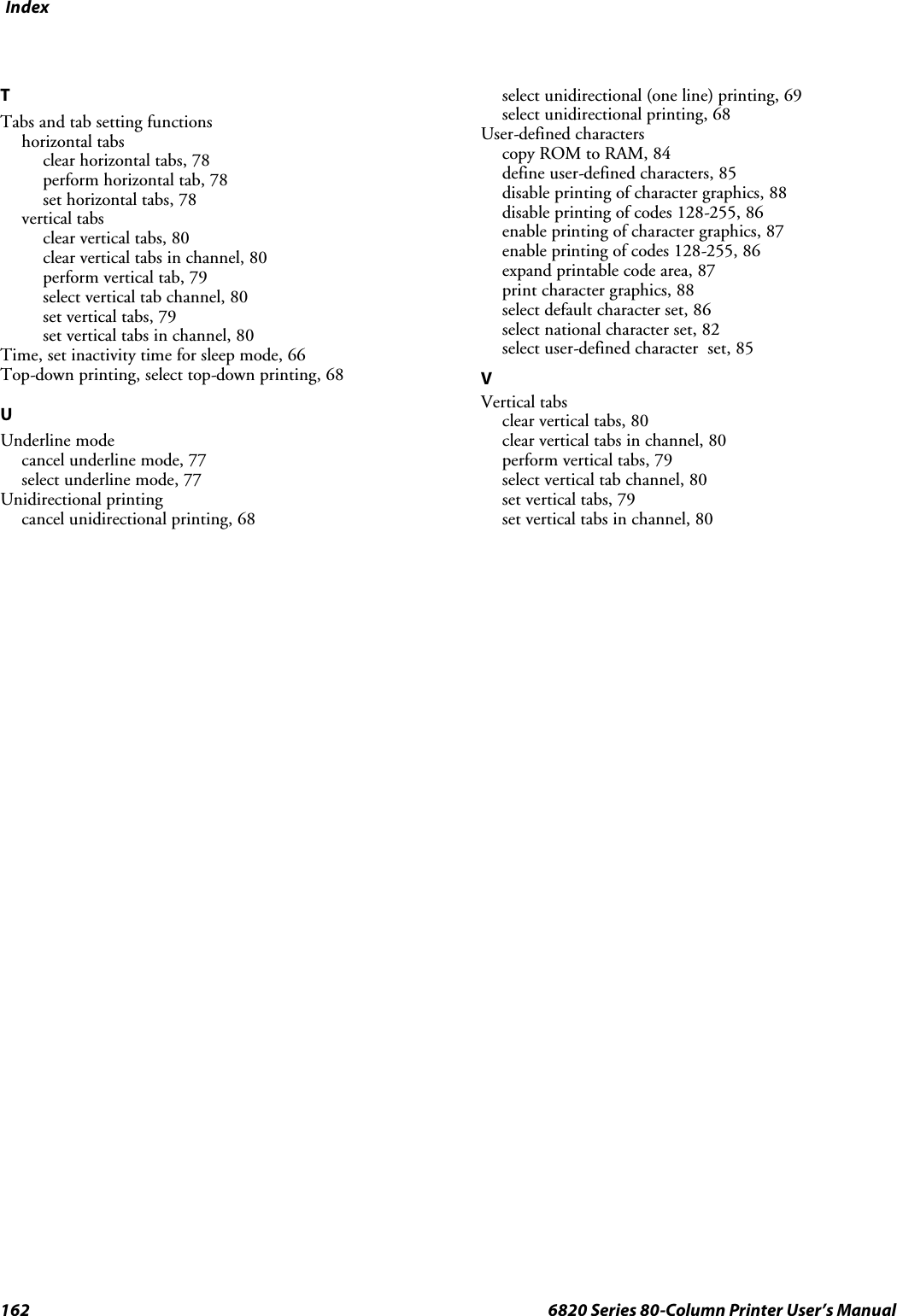
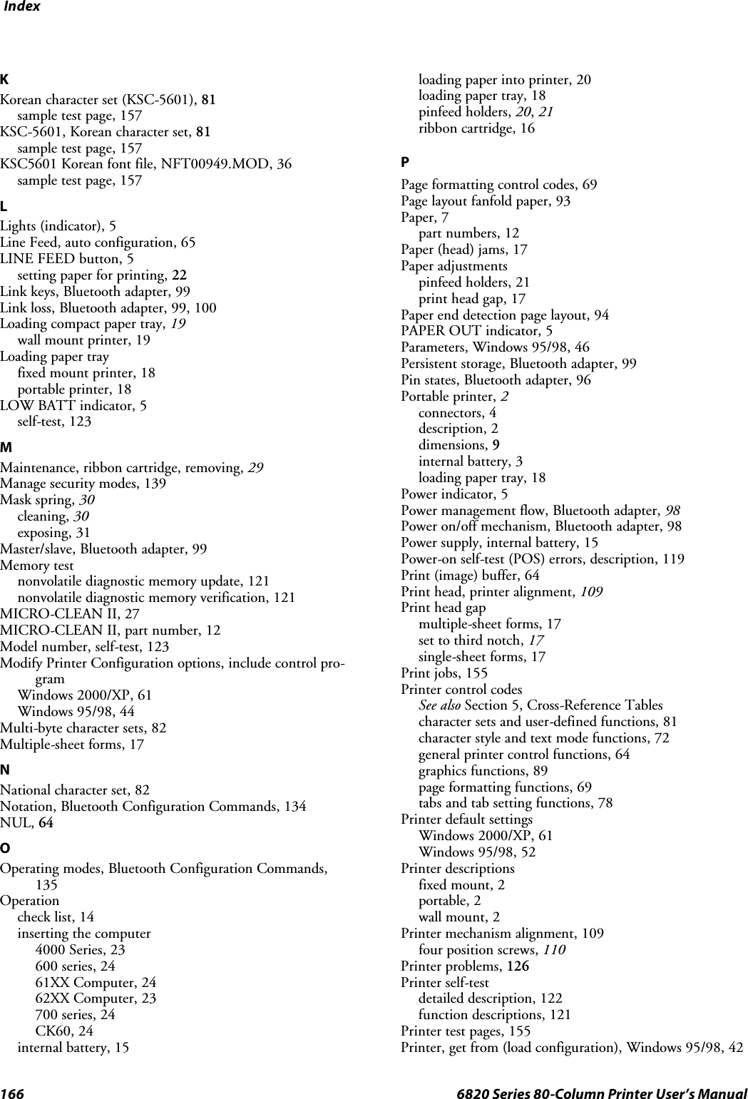
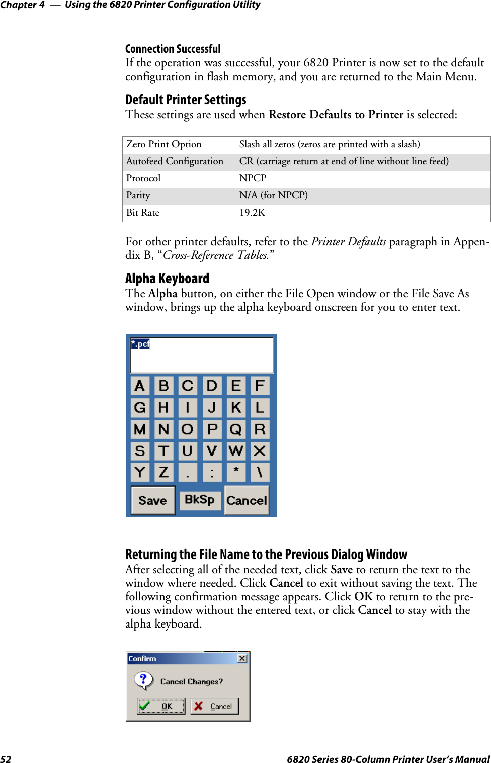
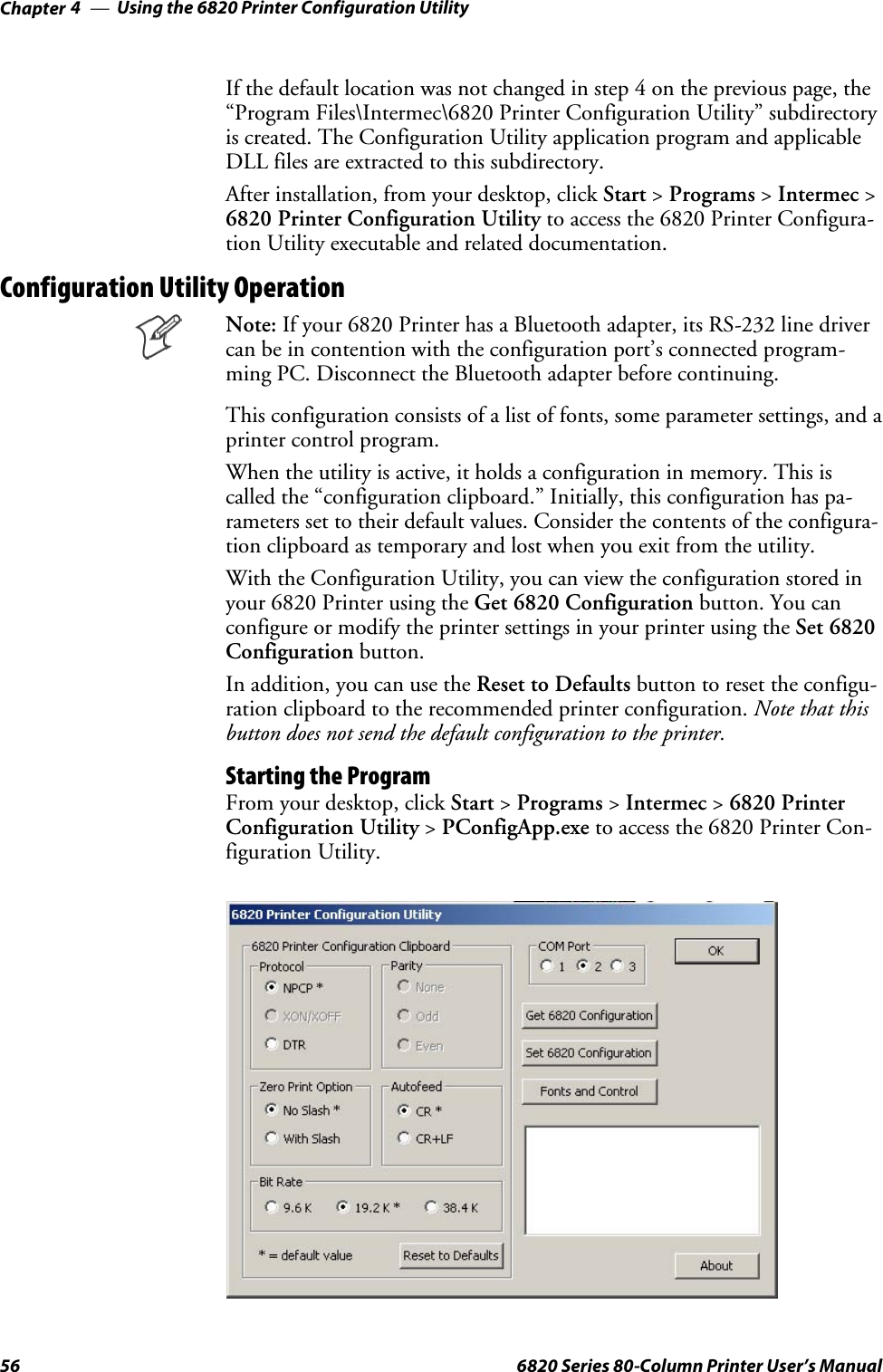
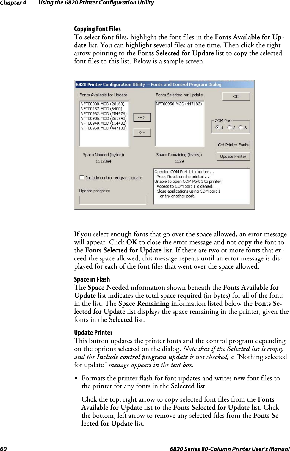
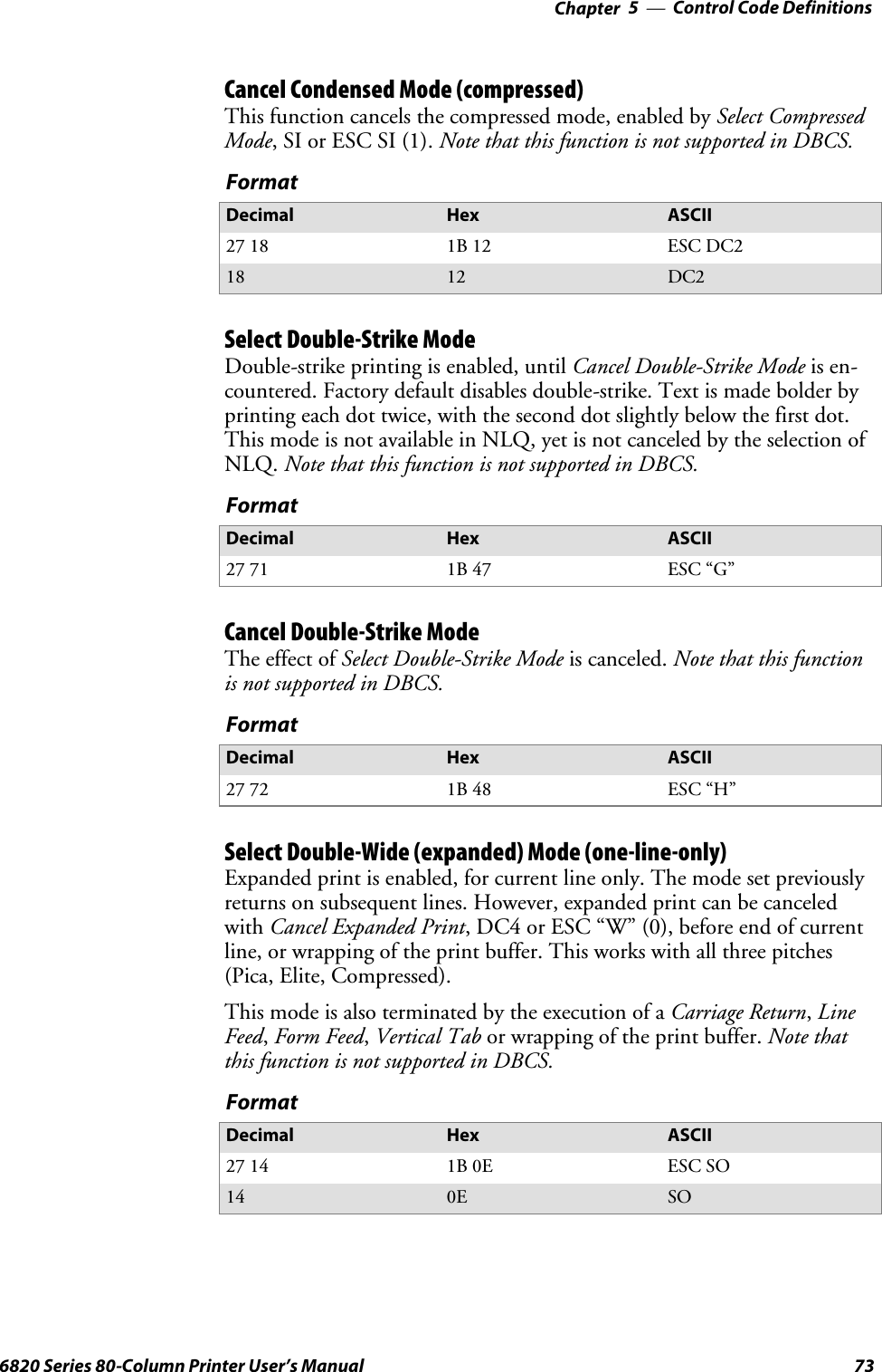
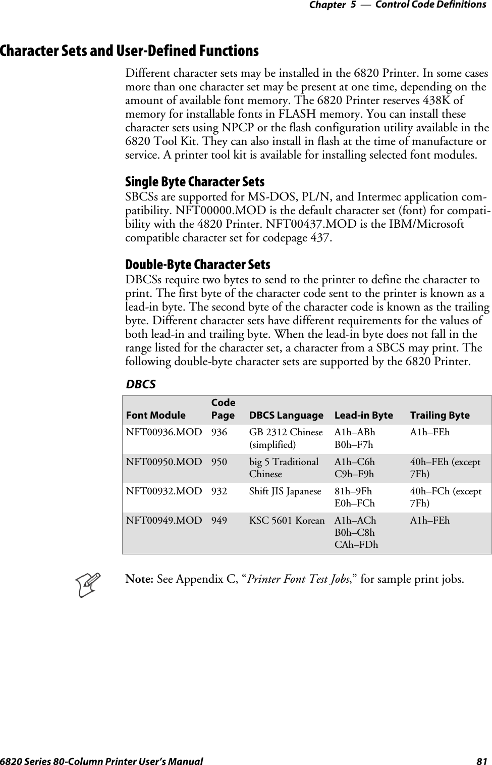
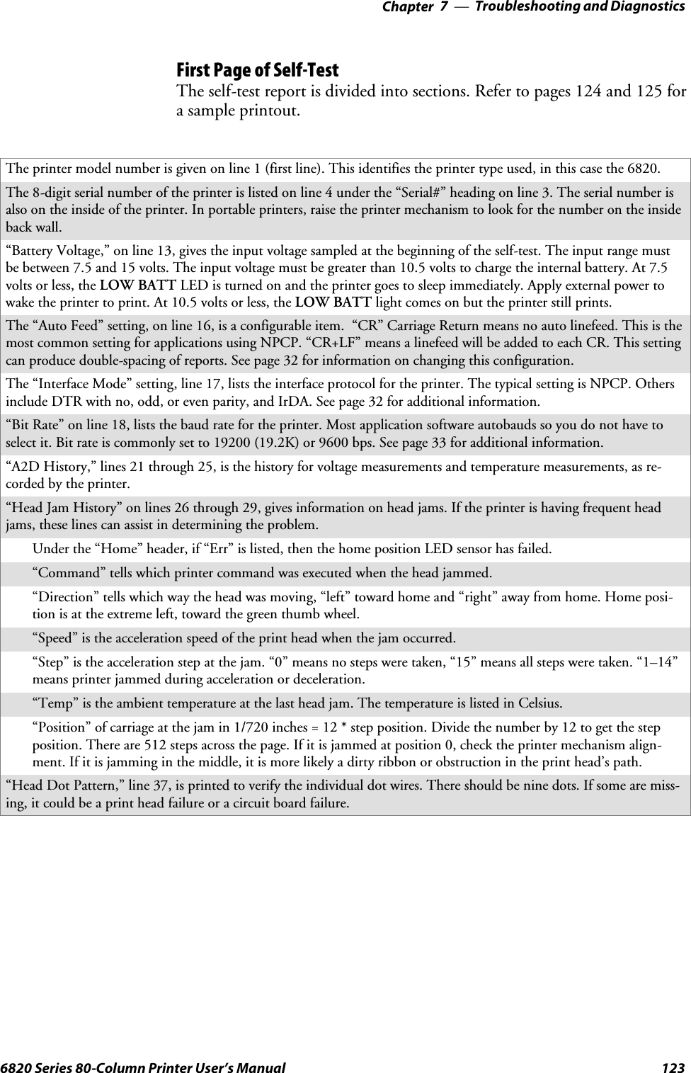
![Using the 6820 Printer Configuration UtilityChapter —450 6820 Series 80-Column Printer User’s ManualConnection SuccessfulIf the connection is successful, the following screen is displayed, the Sendto Printer function is initiated, and the printer’s configuration is updatedto match the working configuration.This screen displays the progress made while updating the printer’s config-uration. Upon completion of this operation, the Total Transfer bar reach-es 100%, and you return to the Main Menu.Save Defaults to PrinterClick Save to Printer on the Main Menu to load the default configurationfile, DEFAULT.PCF, and save it to the printer. This combines the opera-tions of the [from file], the selection of the DEFAULT.PCF file, and the[to printer] into a single button. The following message appears statingthat the working configuration is overwritten. Click Cancel to return tothe Main Menu without loading the default configuration file.](https://usermanual.wiki/Intermec-Technologies/BTS080-2/User-Guide-571475-Page-69.png)
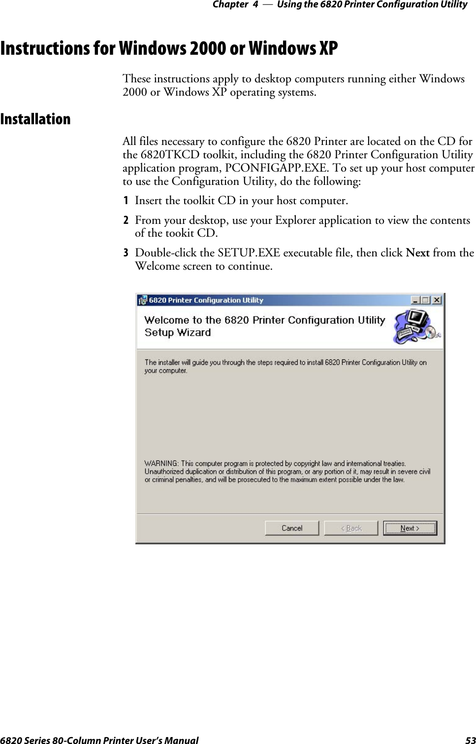
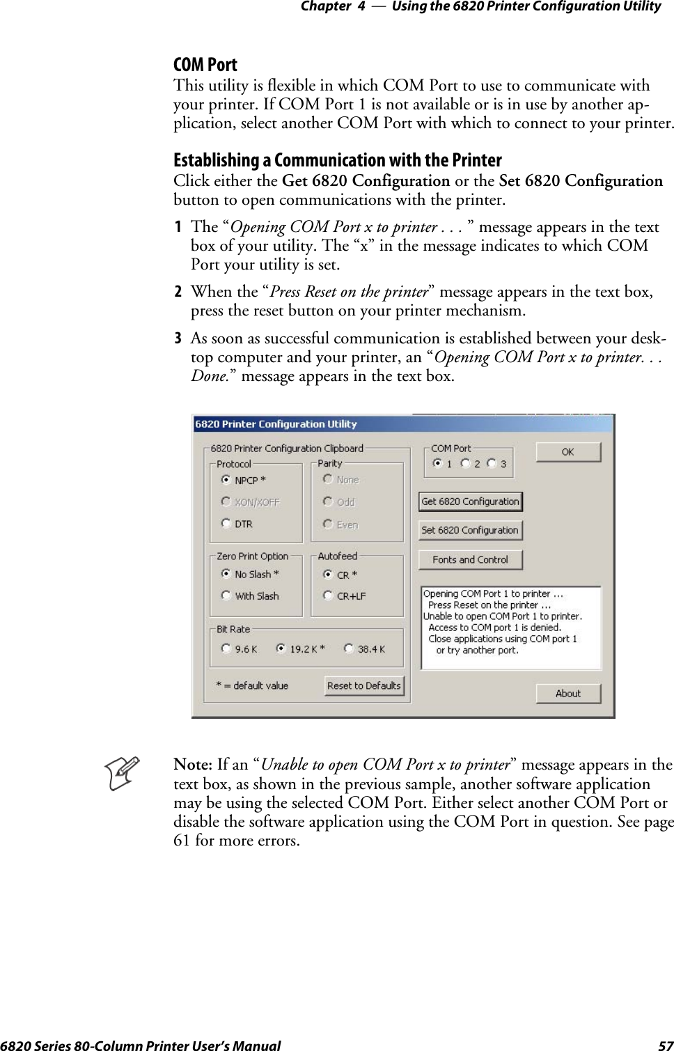
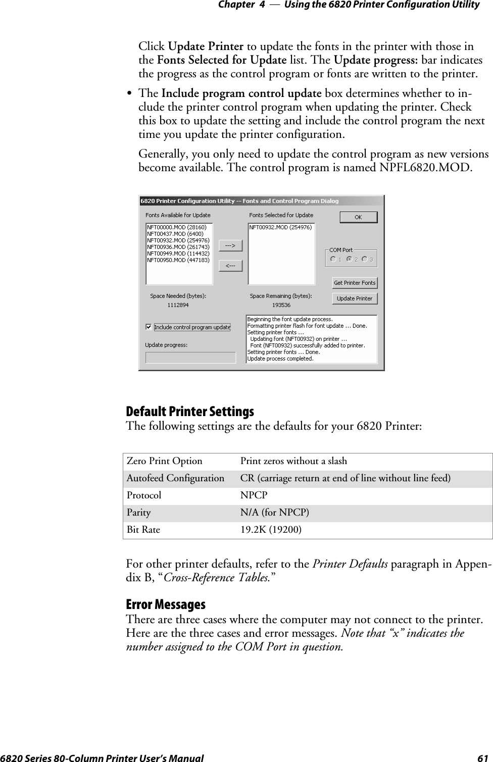

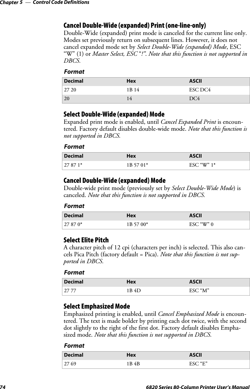
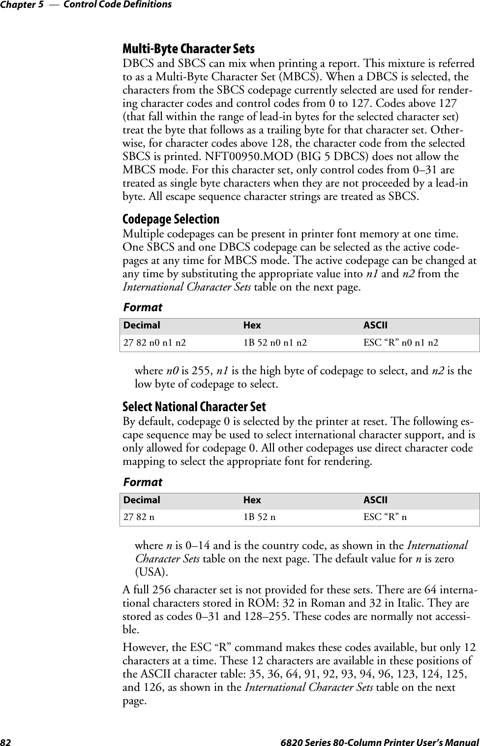
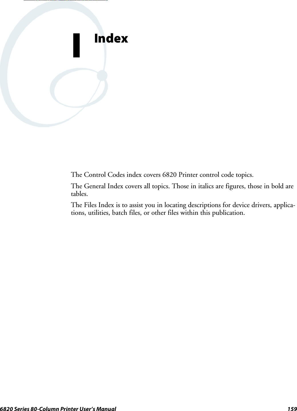
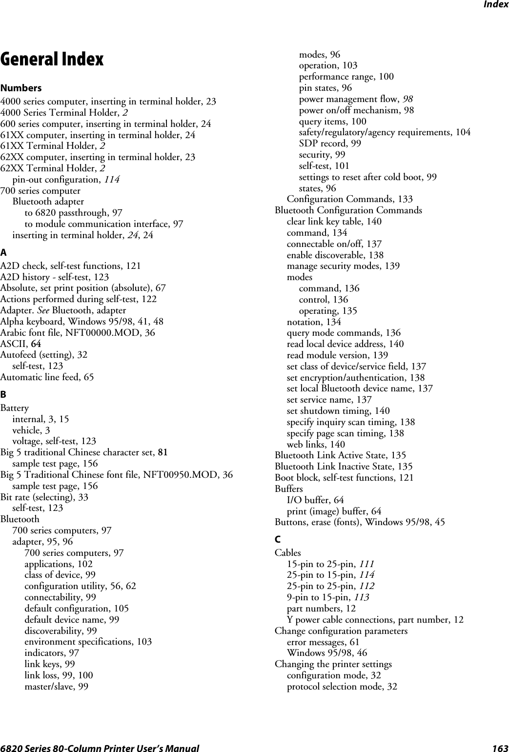
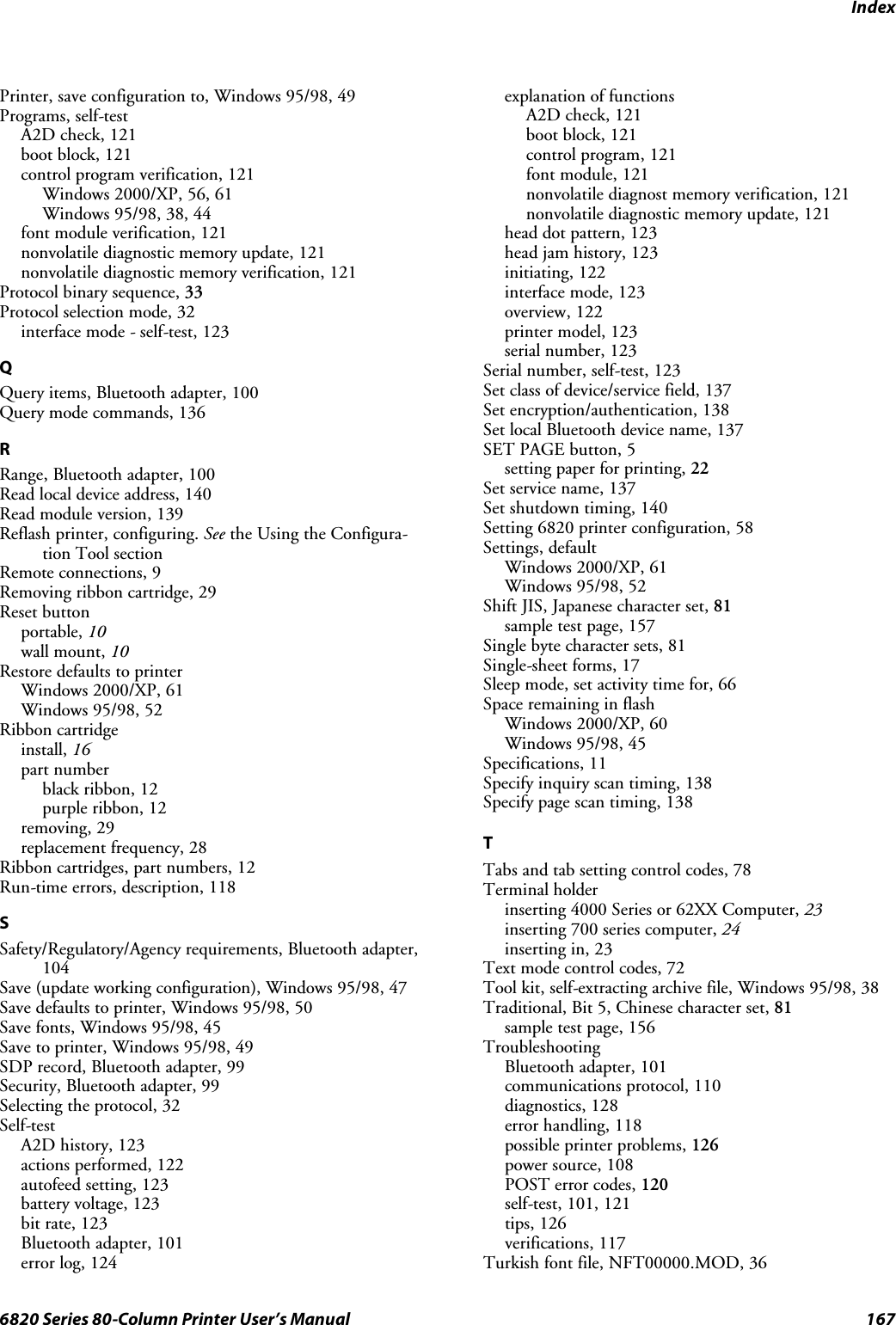
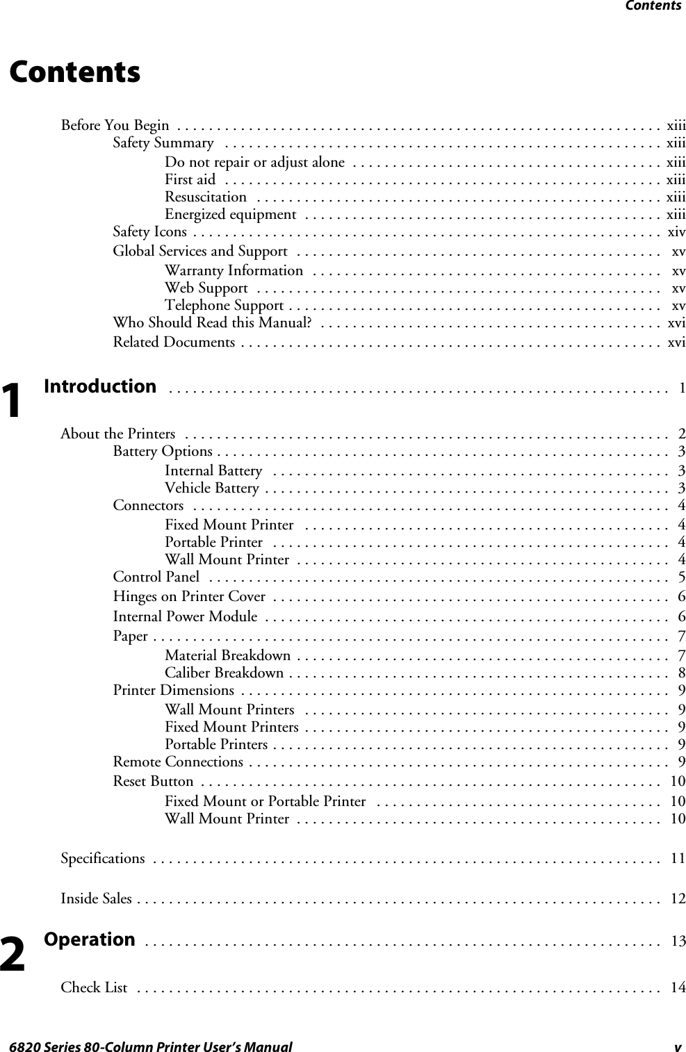
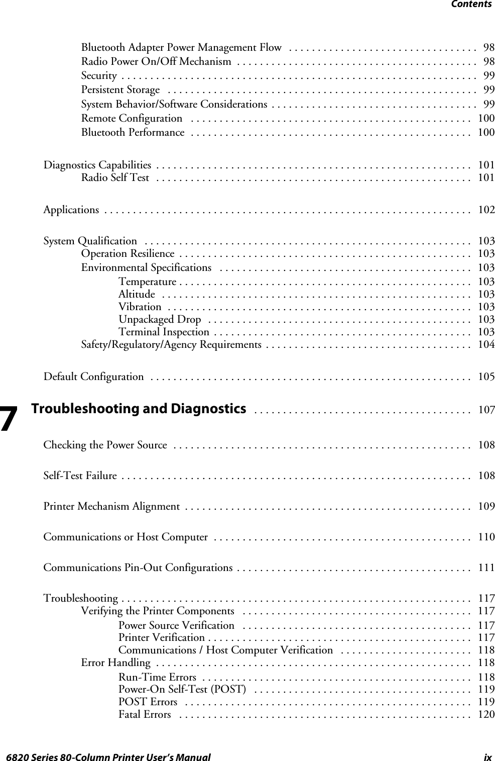
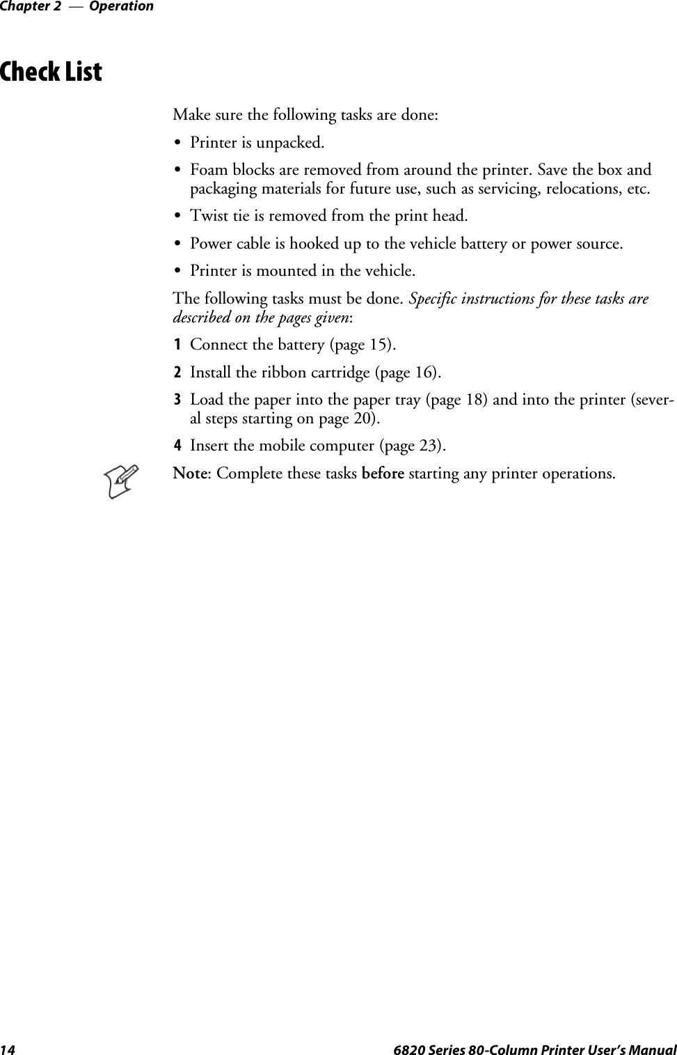
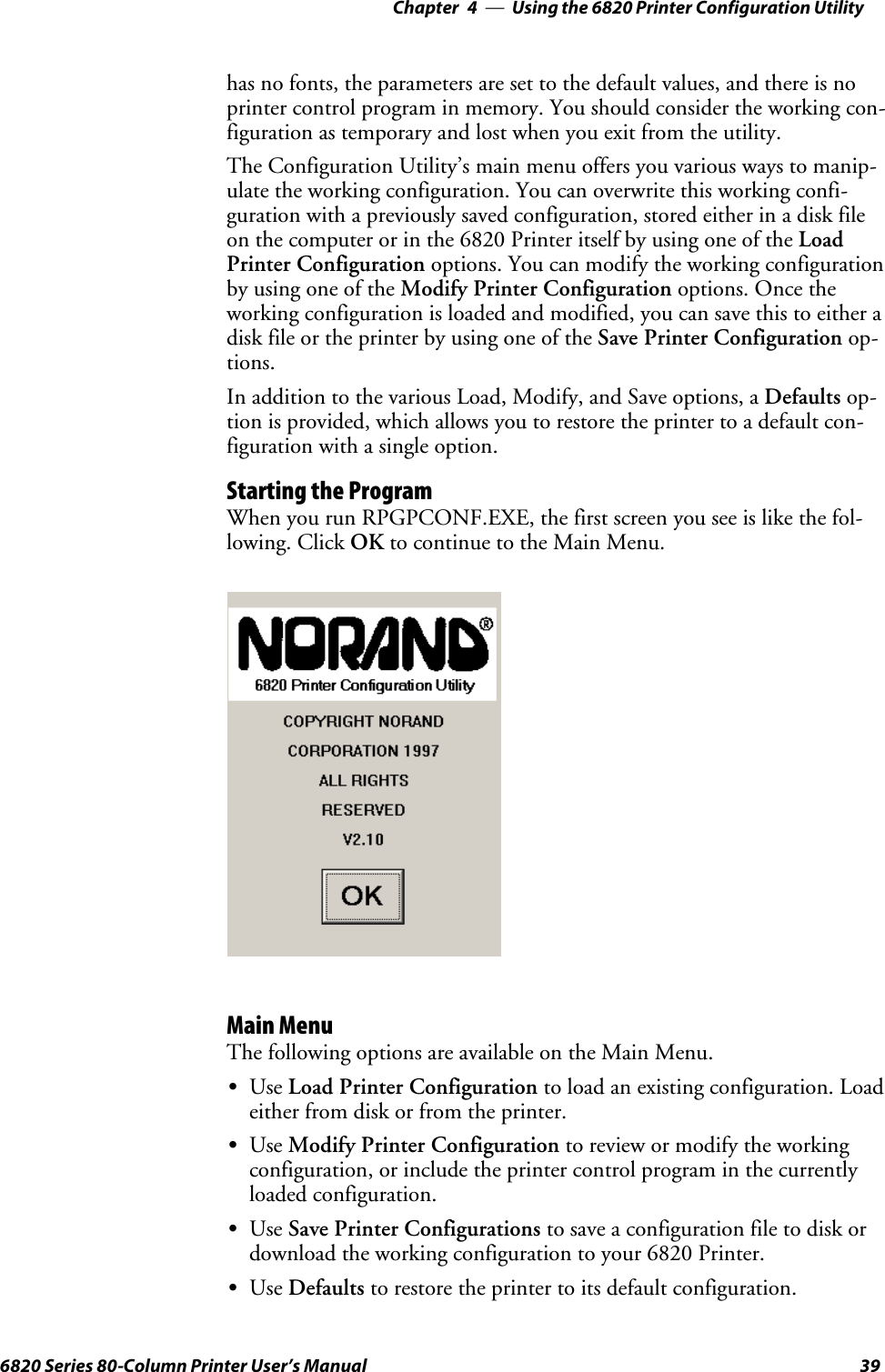
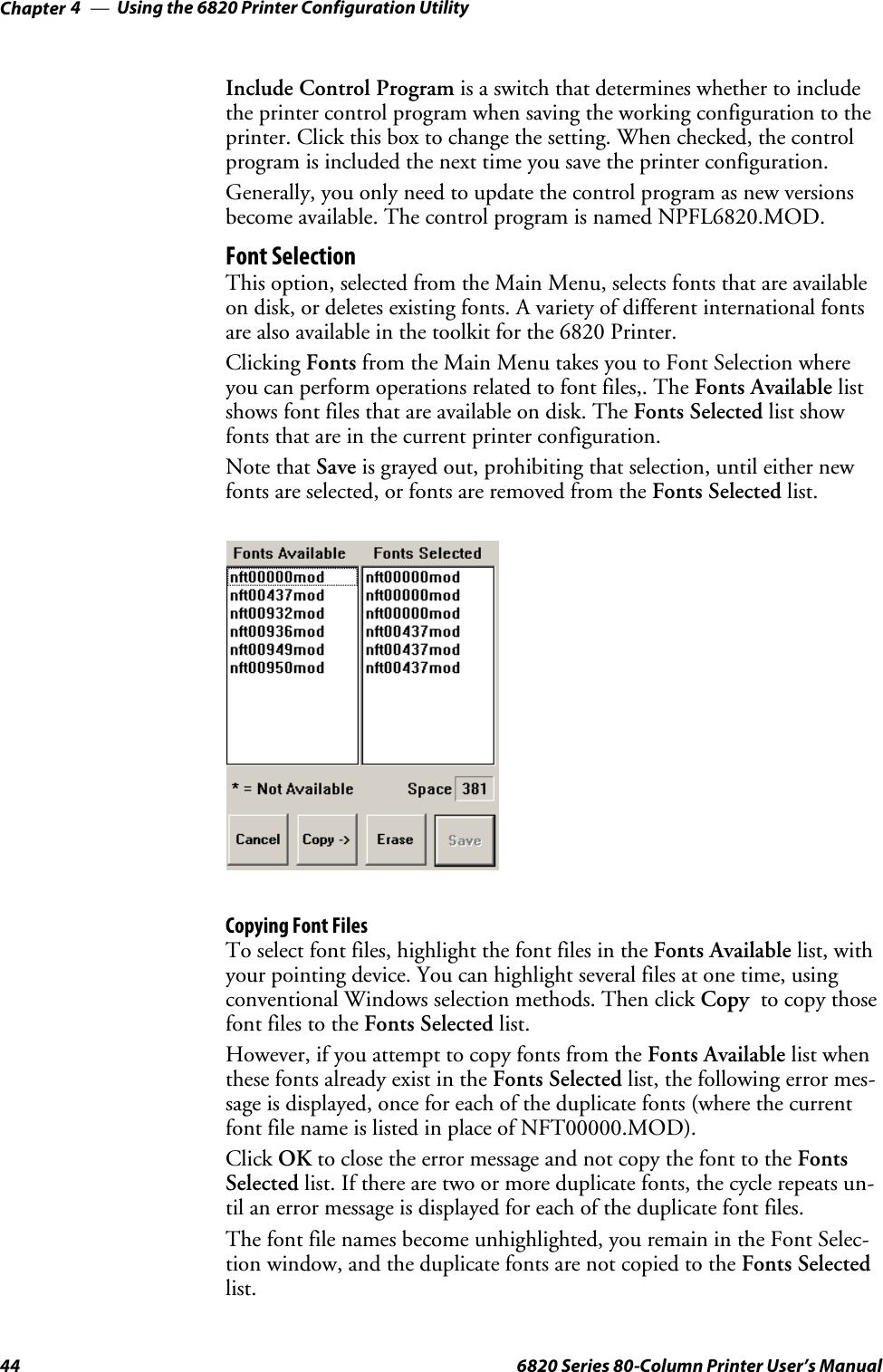
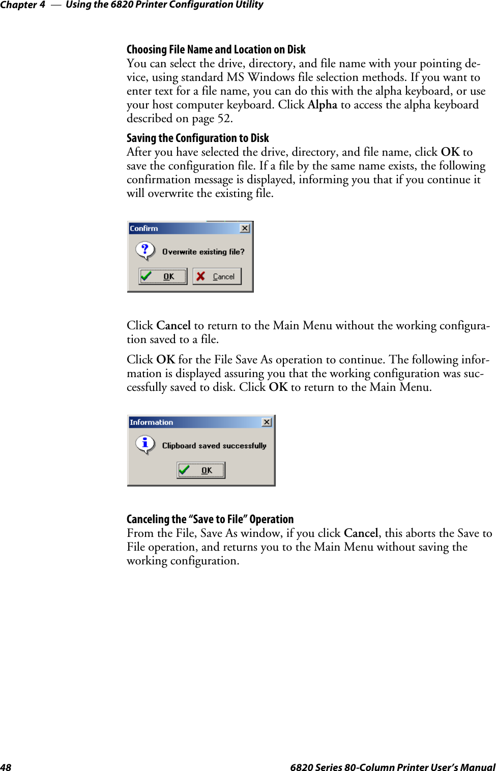
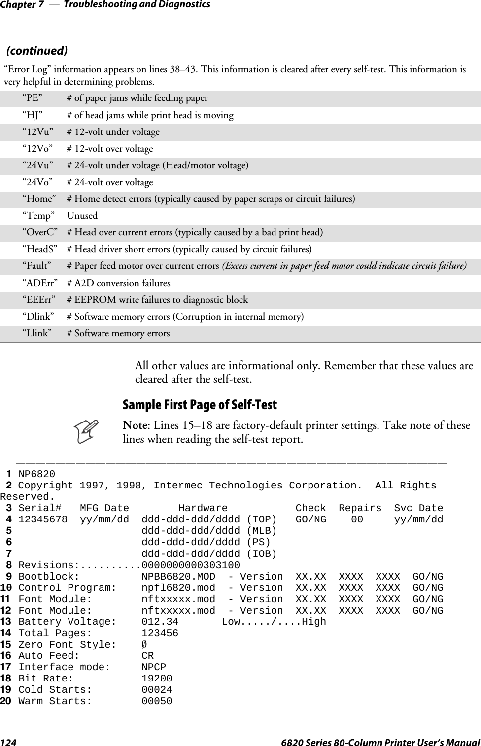
![Control Code Definitions—Chapter 5836820 Series 80-Column Printer User’s ManualInternational Character SetsCountryCountryNumber 35 36 64 91 92 93 94 96 123 124 125 126USA 0 #$@[\]^‘{|}~France 1 # $ à º ç §^ ‘ é ù è ¨Germany 2 #$§ÄÖÜ^ ‘ ä ö ü βEngland (UK) 3 £ $ @ [ \ ] ^ ‘ { | } ~Denmark 1 4 #$@ÆØÅ^‘ æøå~Sweden 5 #¤É ÄÖÅÜ é ä Ö å üItaly 6 #$@º\é^ùà èìSpain 1 7 P $ @ ¡ Ñ ¿ ^ ‘ ¨ ñ } ~Japan 8 #$@[¥]^‘{|}~Norway 9 #¤É ÆØÅÜ é æøå üDenmark 2 10 #$ÉÆØÅÜé æøåüSpain 2 11 # $ á ¡ Ñ ¿ é ‘ í ñ ó úLatin America 12 #$á¡ Ñ¿ éüí ñóúHebrew 13 Note: Hebrew fonts are available in the supplied font files. See “Hebrow Character Fonts”below.Greek 14 Note: Greek fonts are available in the supplied font files. See the “Greek Character Sets”table on the next page..Hebrew Character FontsHebrew characters represented by decimal values 38 and 65 through 90are represented by the following 7x7 font descriptions.*.*.*.. ....*.* *.*.*.* *.*.*.* ....*.* *.*.*.* *.*.*.* *..*.*.....*.. ......* .....*. .....*. ......* ...*... .*...*. *..*..*....*.. ....*.* .....*. *....*. ......* ...*... *....*. *..*..*....*.. ...*..* .....*. *....*. ......* ...*... *....*. *.....**.*.*.* ..*...* .....*. *....*. ......* ...*... *....*. *....*........ ....... ....... ....... ....... ....... ....... *.*.*......... ....... ....... ....... ....... ....... ....... .......65 66 67 68 69 70 71 72....... ....... ....... *...... ....... ....... ....... ...........*.* ..*.*.* *.*.*.. *.*.*.* *.*.*.* *..*... ....*.* ....*.*......* ......* ......* ......* *.....* .*.*.*. ......* ......*......* ......* ......* .....*. *.....* ..*...* ......* ......*....... ......* ......* ....*.. *.....* .*....* ......* ......*....... ......* *.*.*.. .*.*... *.*.*.* *...*.* ......* ..*.*.*....... ....... ....... ....... ....... ....... ....... .............. ....... ....... ....... ....... ....... ....... .......73 74 75 76 77 78 79 80....... ....... ....... ....... ....... ....... ....... .......*.*.*.* *.....* *.*.*.* *.*.*.. *....*. *.....* *.*.*.* *.*.*.*..*...* *.....* *.....* *.....* .*..*.. .*...*. ......* ......*.*....* .*...*. *.*...* *.*...* ..*.*.. ...*... .*....* ......**....*. ..*.*.. ......* ......* ......* .....*. *.*.*.* ......**.*.*.. *.*.*.* ......* *.*.*.. ......* *.*.*.* *...... ......*....... ....... ......* ....... ......* ....... *...... .............. ....... ....... ....... ....... ....... ....... .......81 82 83 84 85 86 87 88.....*. ....... .......*..*..* ..*.*.* *.....**..*..* ..*...* .*....**..*..* ..*...* .*.*.*.*.*..*. ..*...* *....*.*...*.. *.*...* *.....*....... ....... .............. ....... .......89 90 38](https://usermanual.wiki/Intermec-Technologies/BTS080-2/User-Guide-571475-Page-102.png)
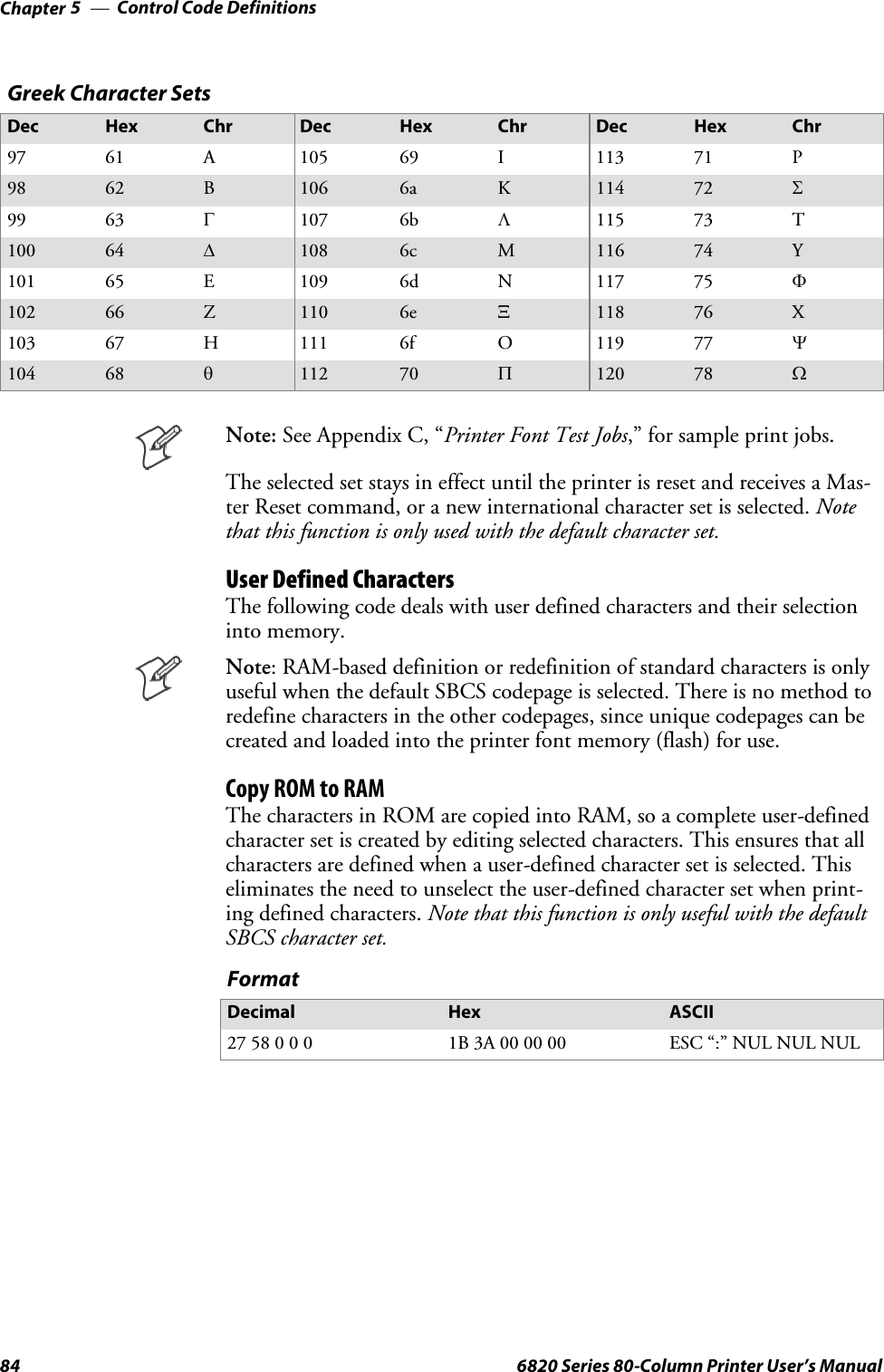
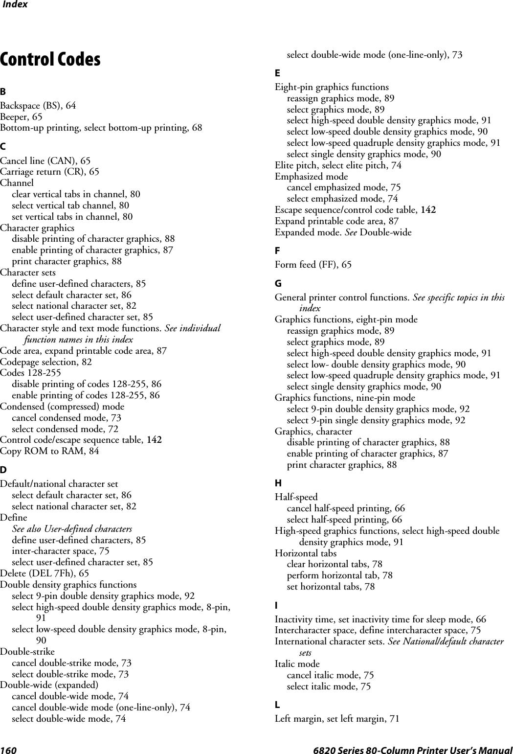
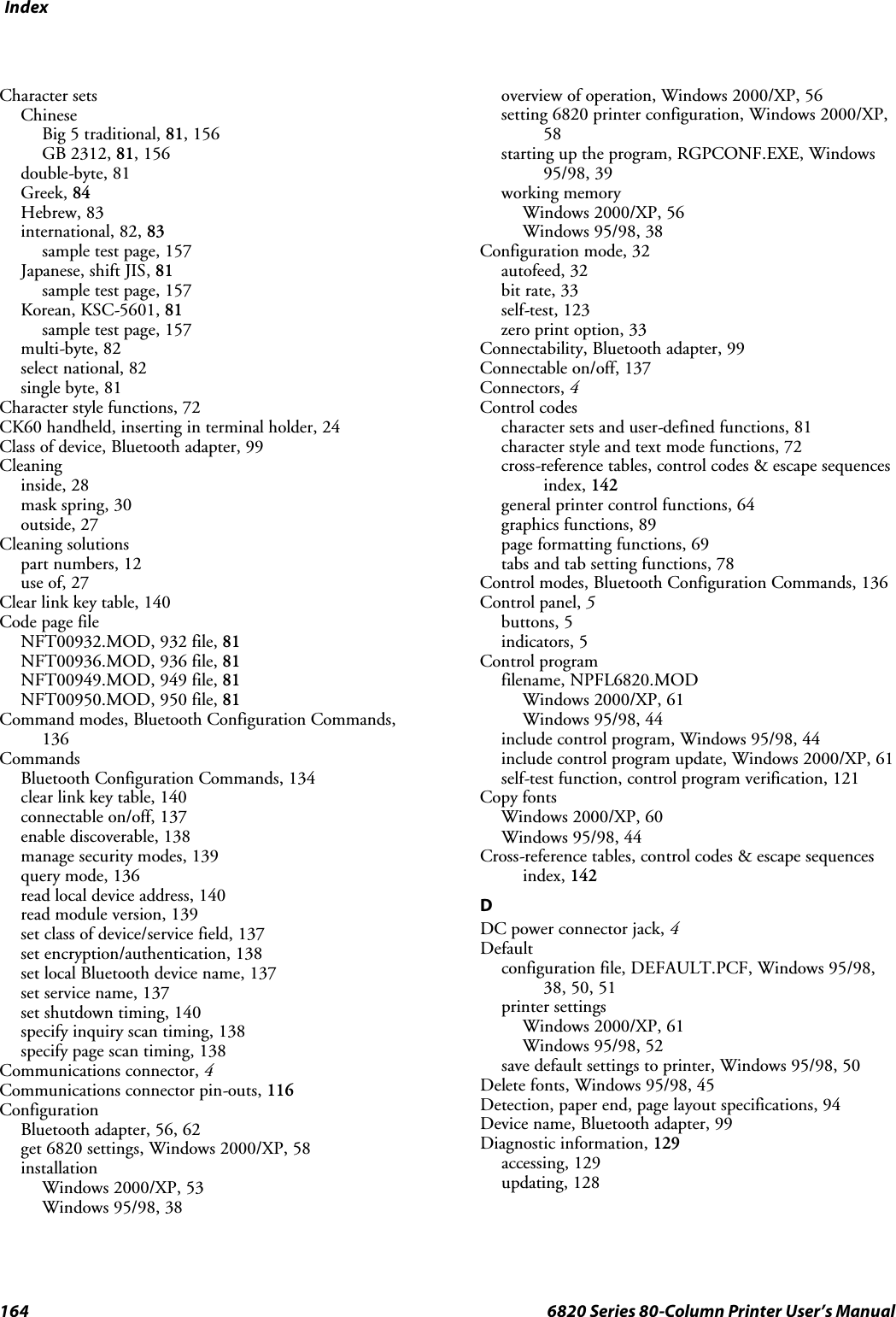
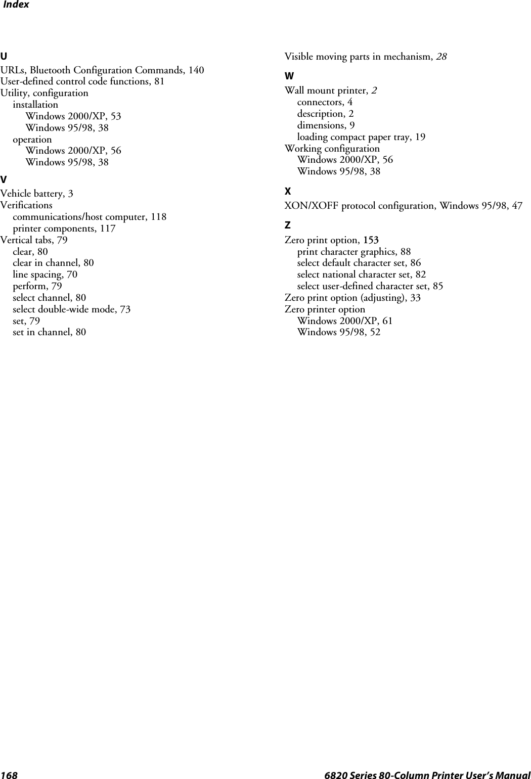
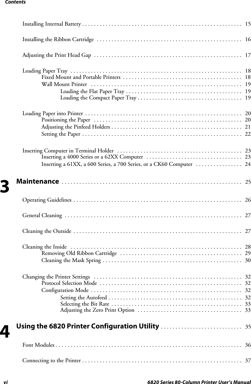
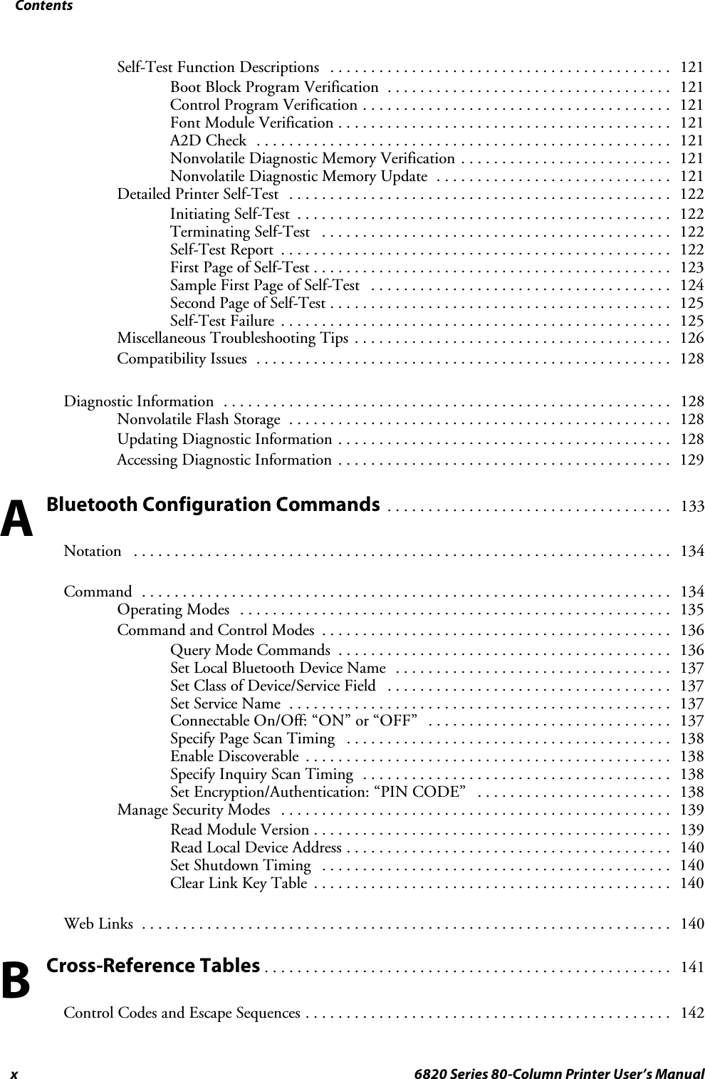
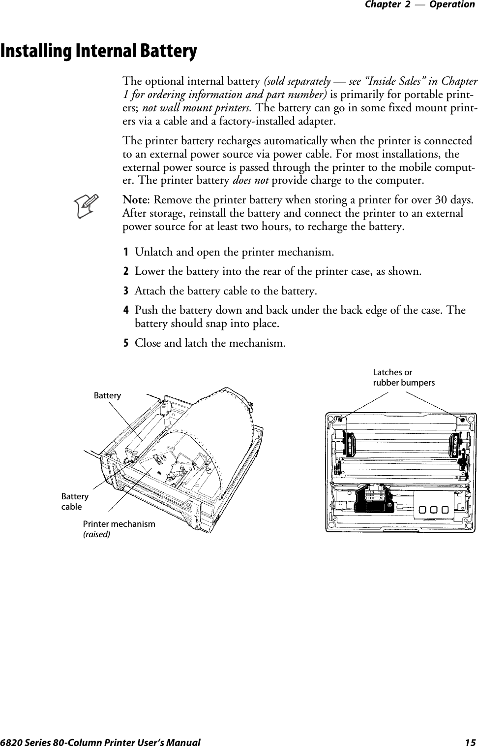
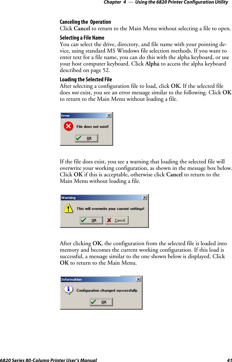
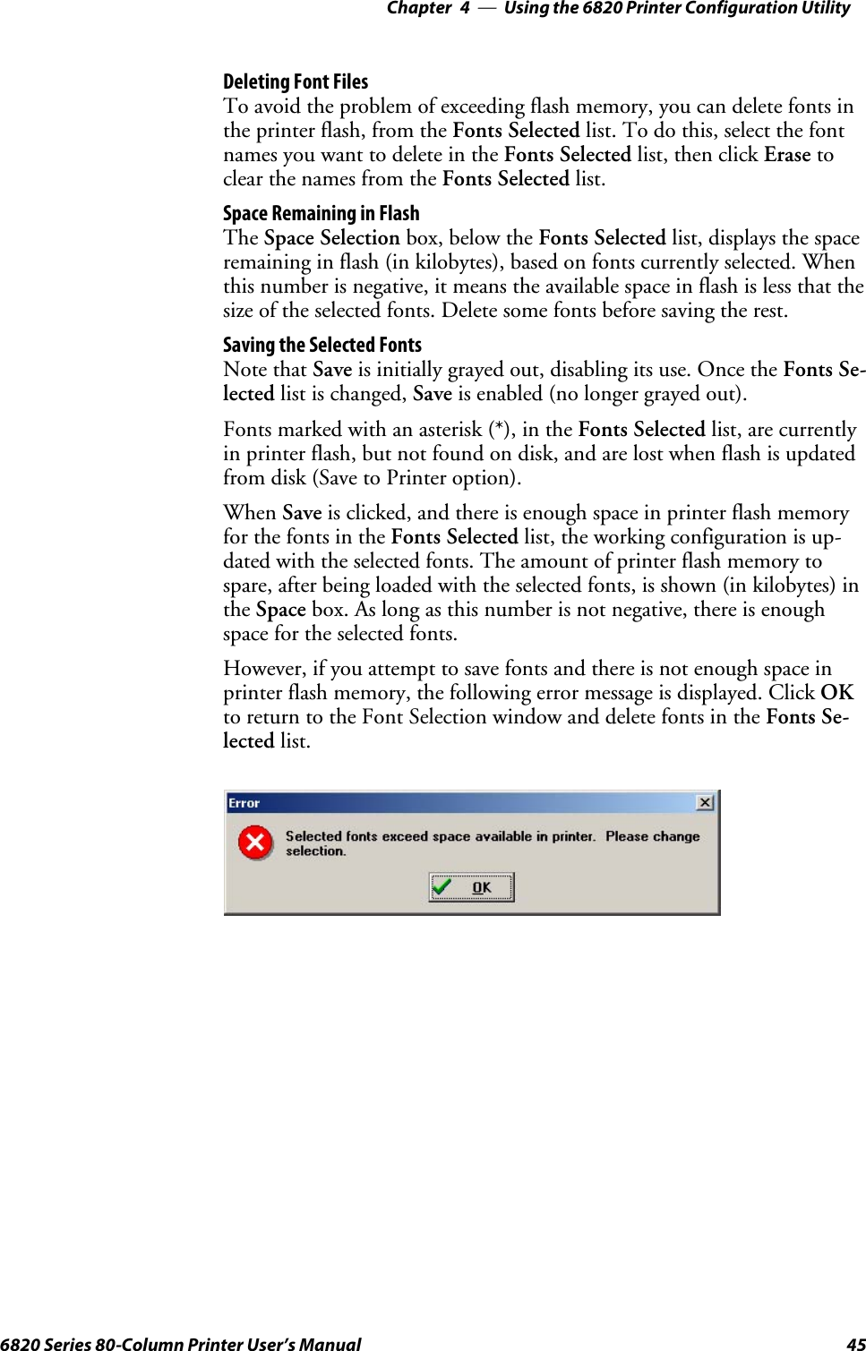
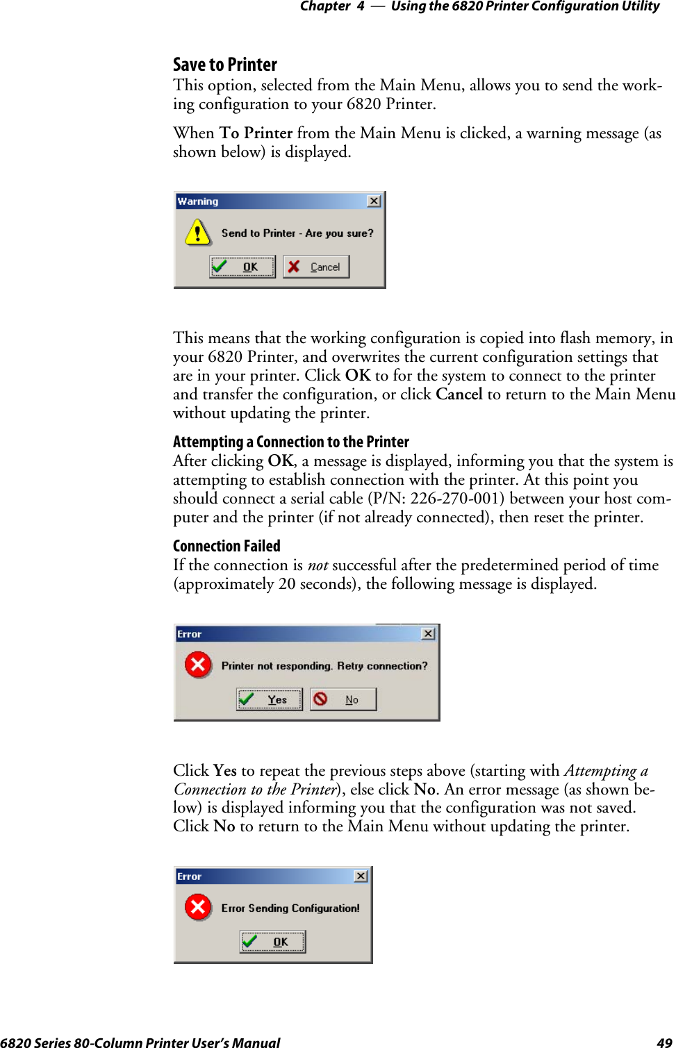
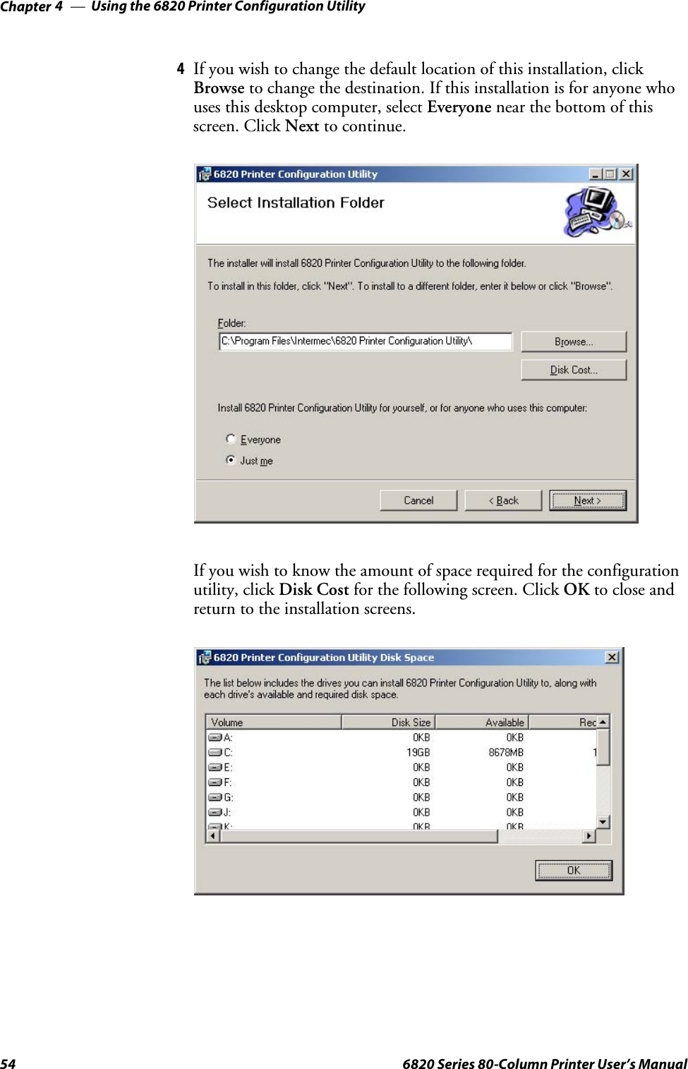
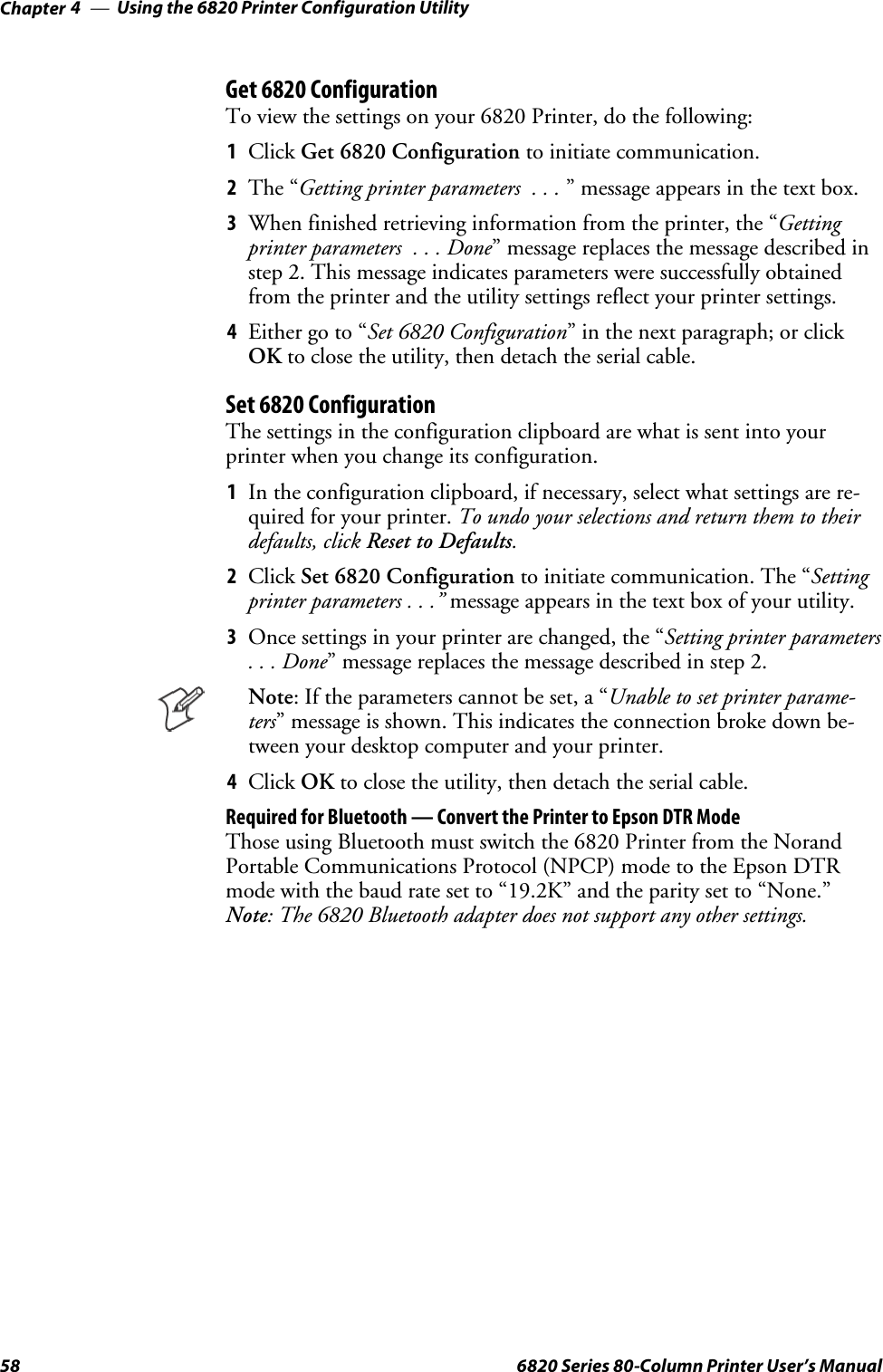
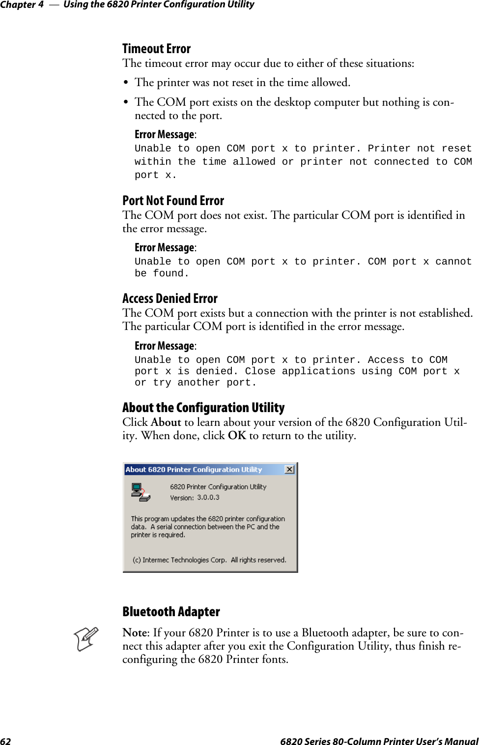
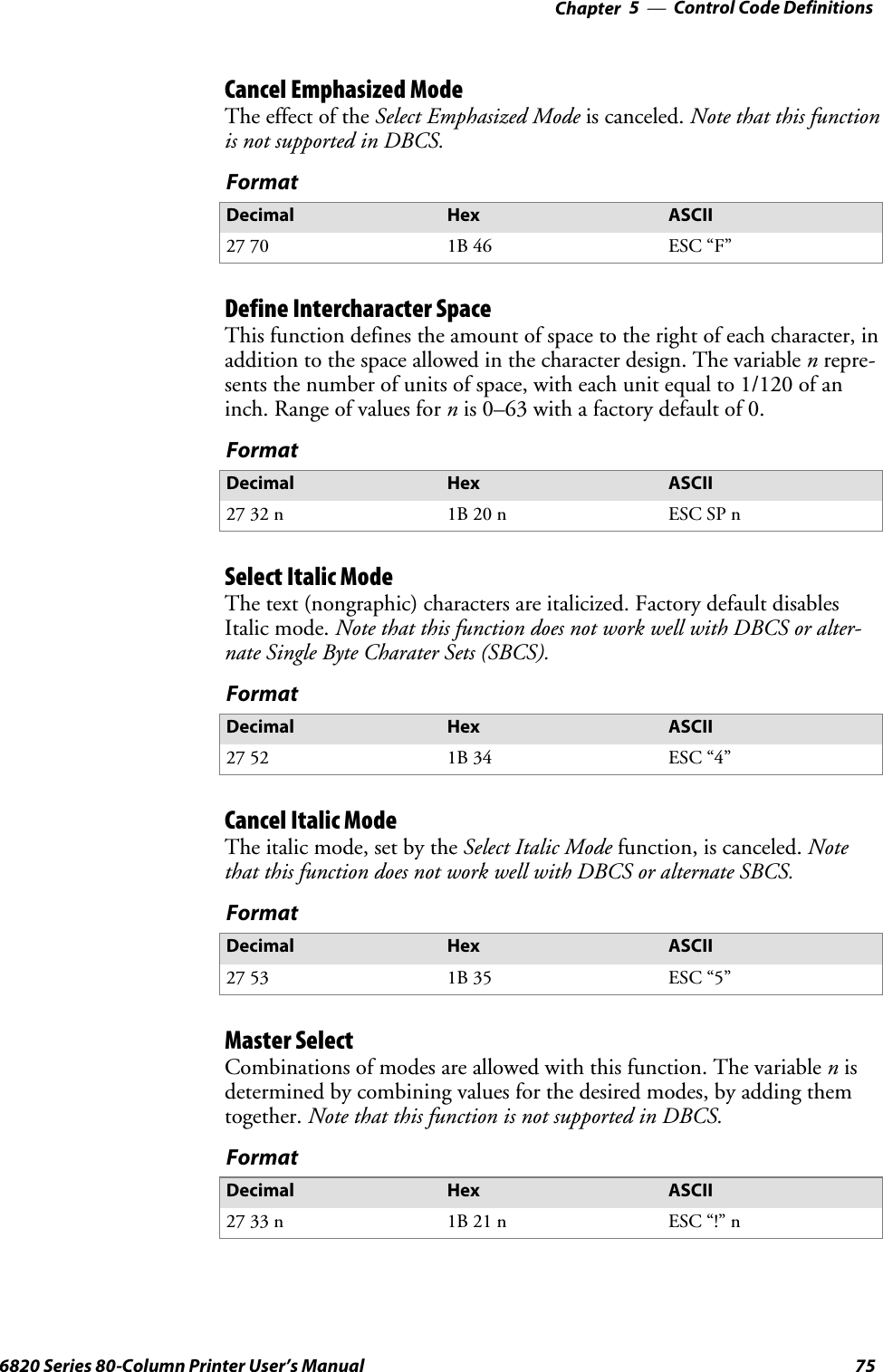
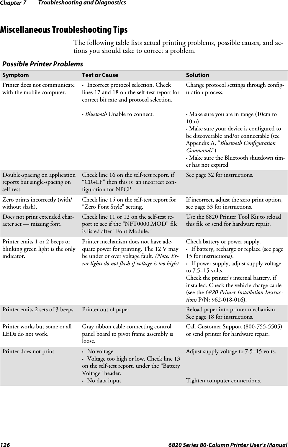
![Bluetooth AdapterChapter —6100 6820 Series 80-Column Printer User’s ManualRemote ConfigurationYou can query the following items:SDiscoverable State [Get/Set]SConnectable State [Get/Set]SBondable State [Get/Set] (Authentication)SEncryption State [Get/Set]SDevice Name [Get/Set]SDevice Address[Get]SClass of Device[Get/Set]SService Name [Get/Set]SBluetooth Profile [Get]SBluetooth Passkey [Set] (Getthefactthatitisset)SRadio Shutdown TimeoutBluetooth PerformanceSRange — Operating range is expected to range from a minimum separa-tion of 10cm to over 10m with a 700 Color or CK60 Handheld Com-puter.SLink Loss can occur when going in or out of range while communicat-ing with other Bluetooth devices. Degradation in range and datathroughput is expected when in automobile cabins or when involved inintermittent loss of line-of-sight (communications across a busy road).](https://usermanual.wiki/Intermec-Technologies/BTS080-2/User-Guide-571475-Page-119.png)
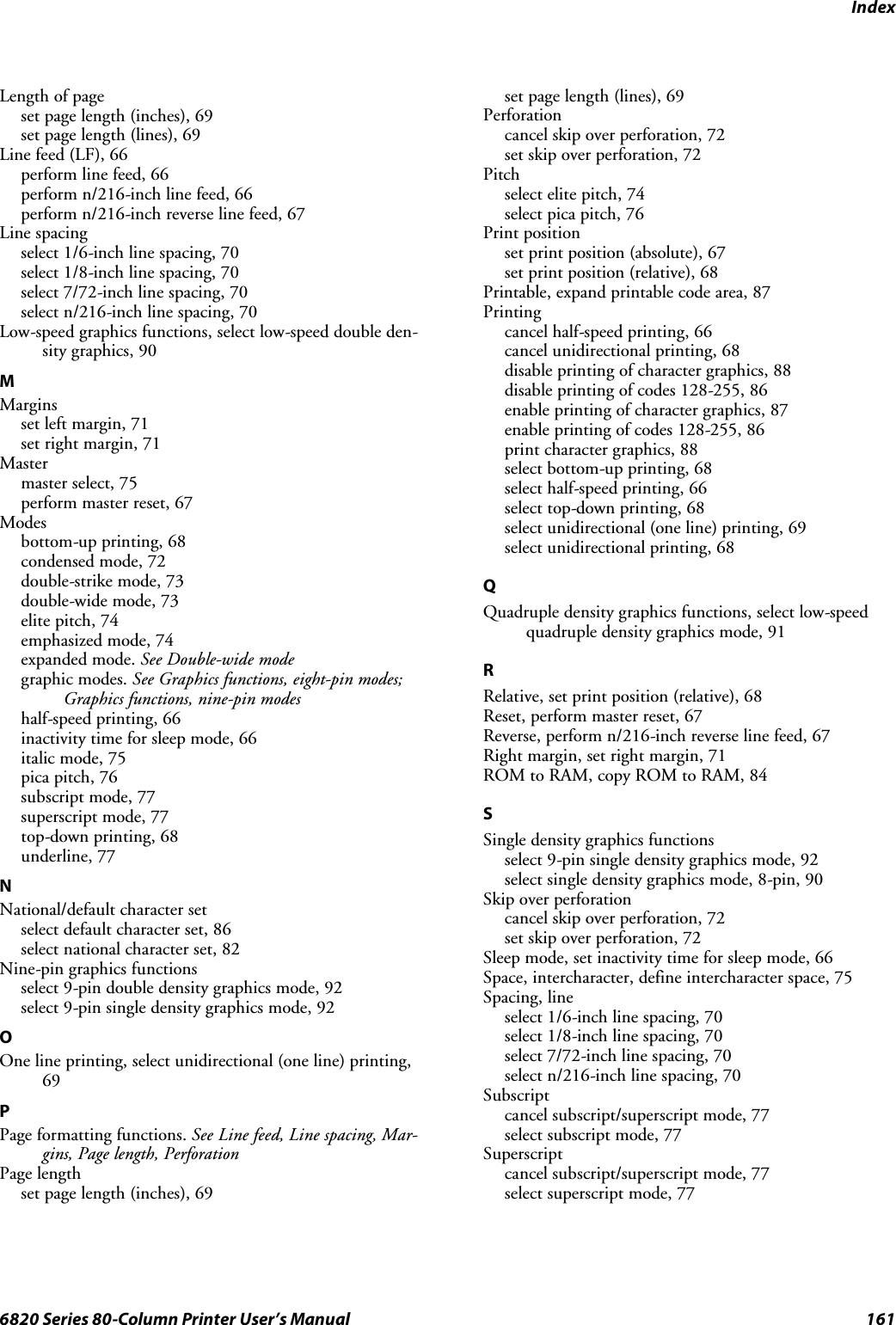
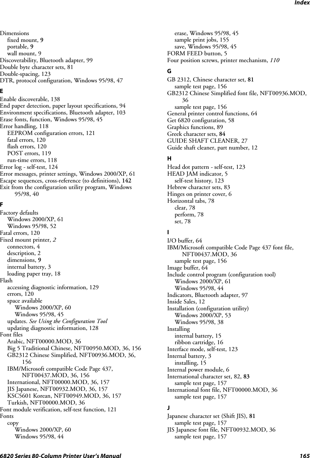
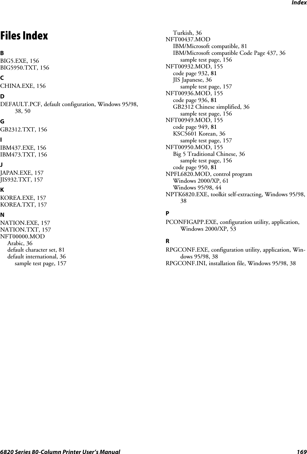
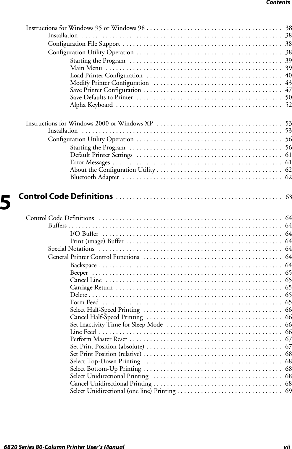
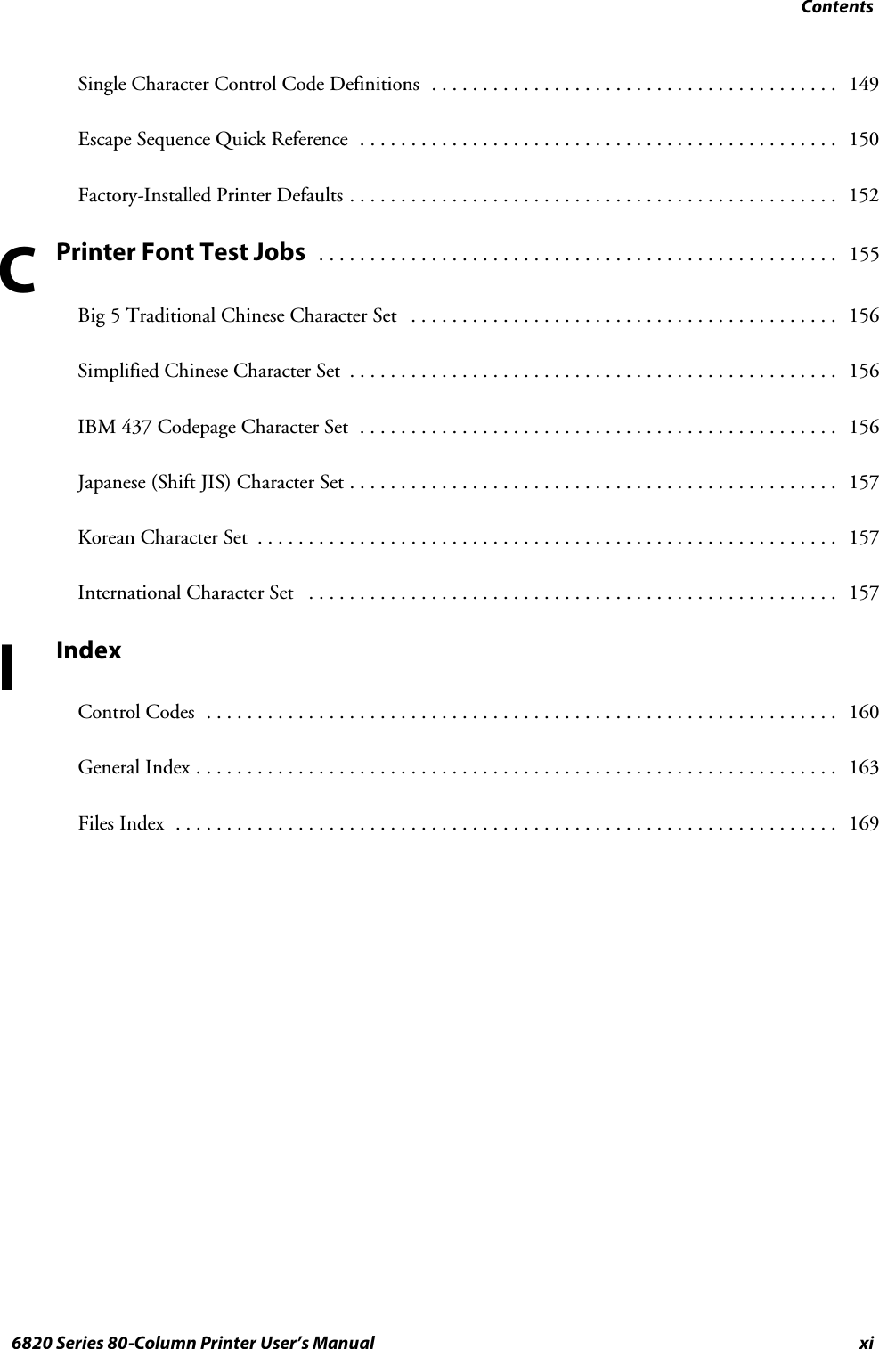
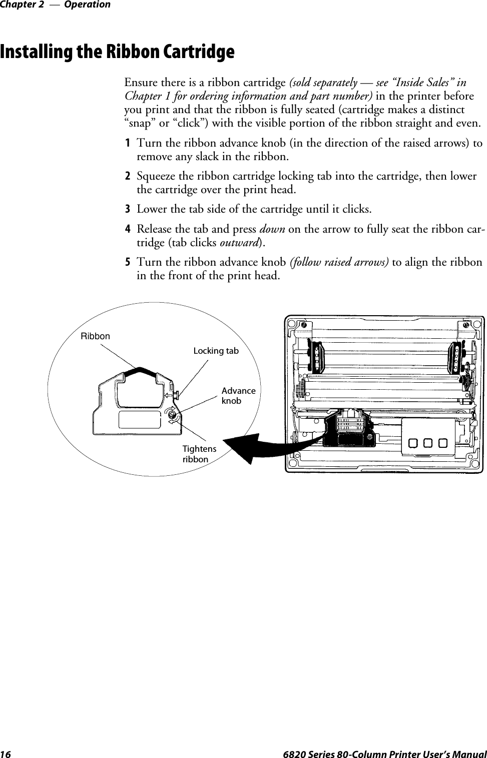
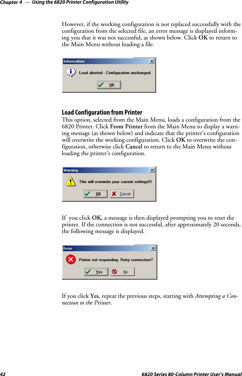
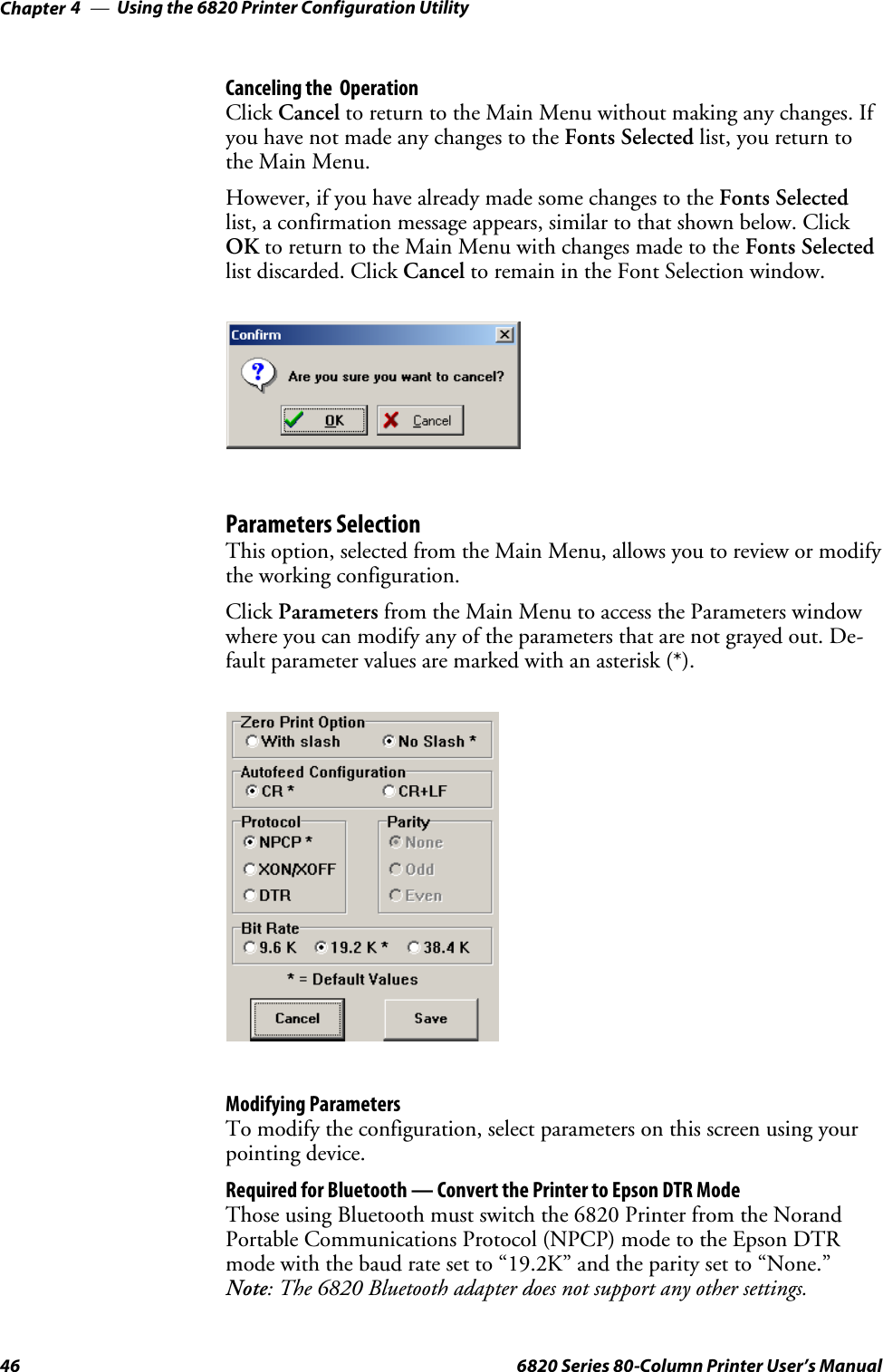
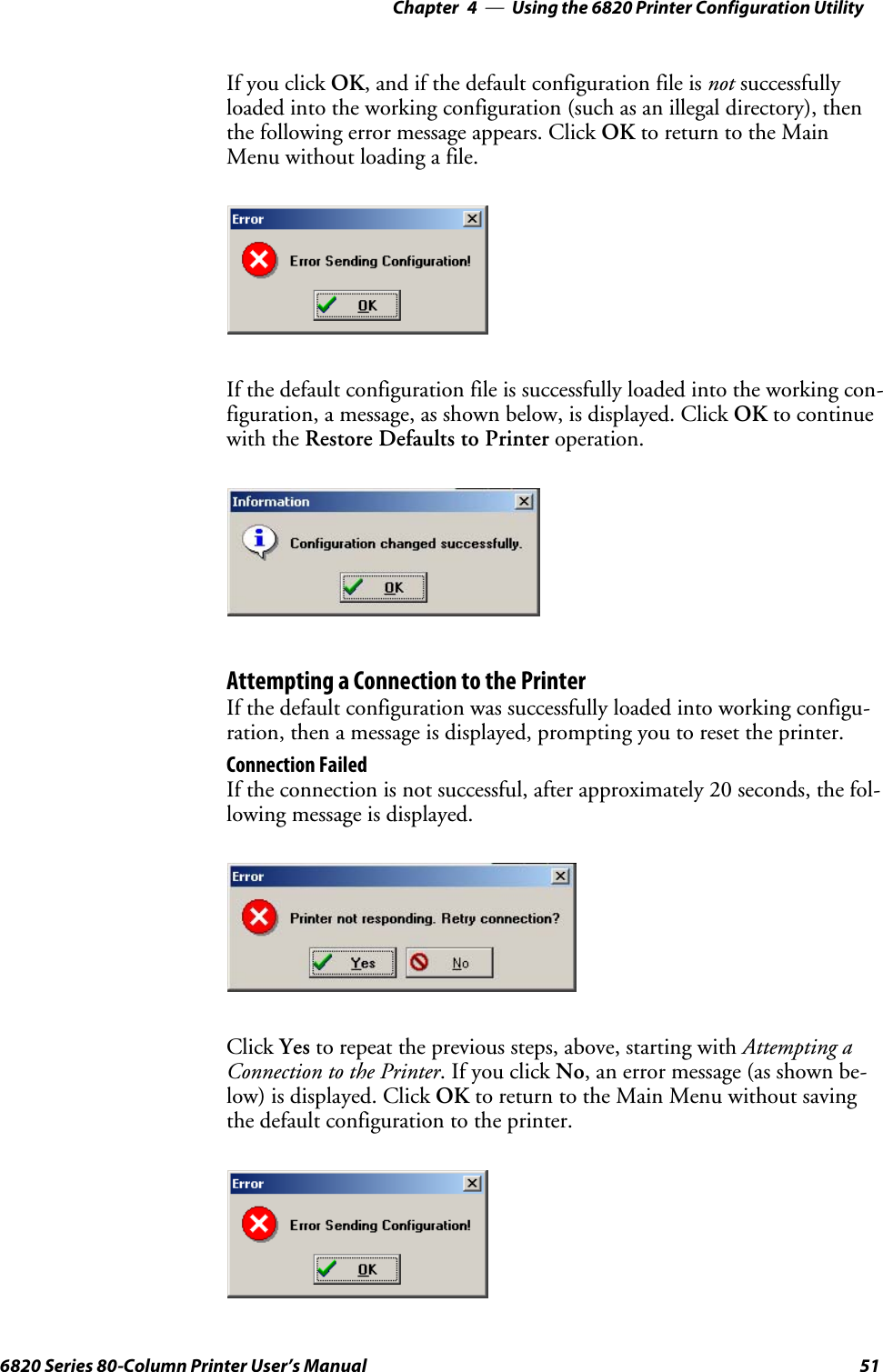
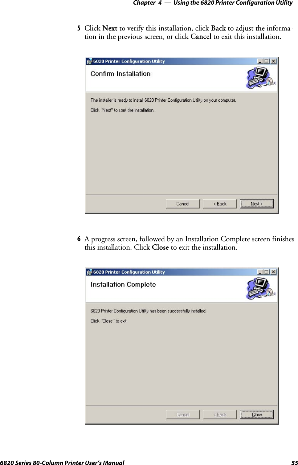
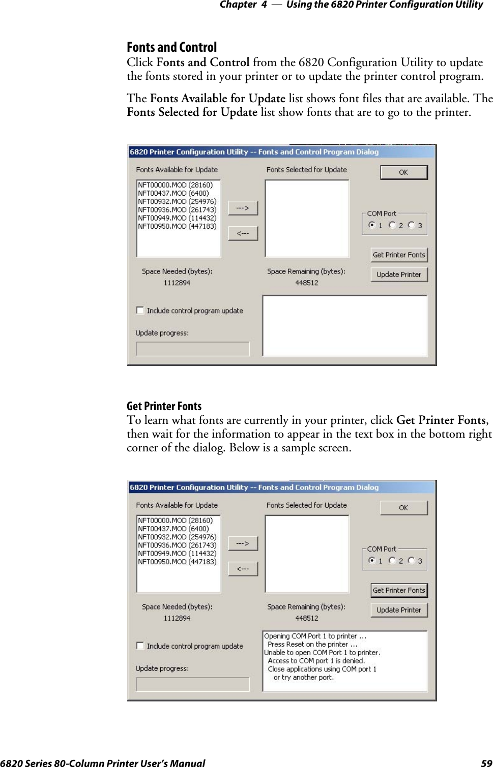
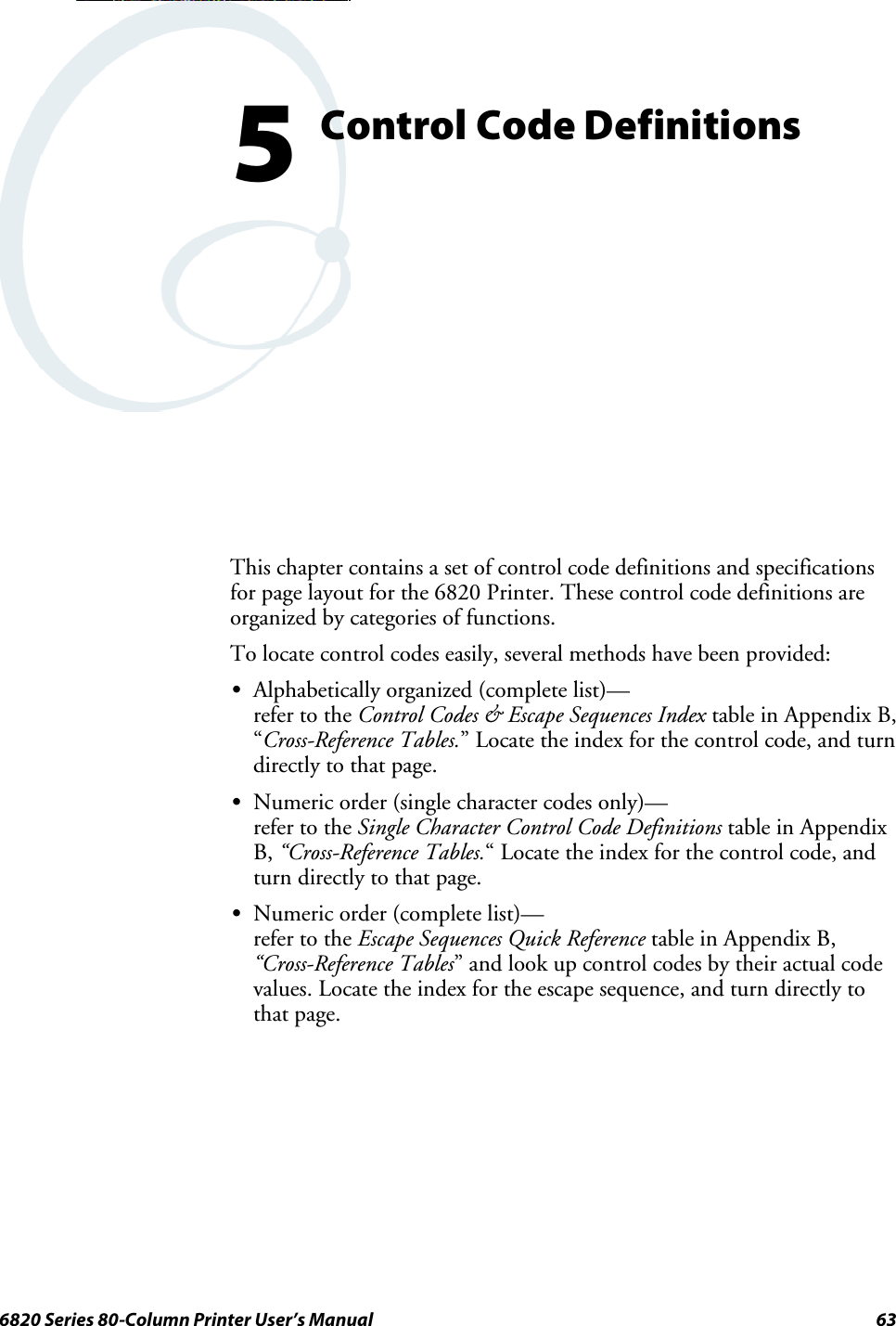
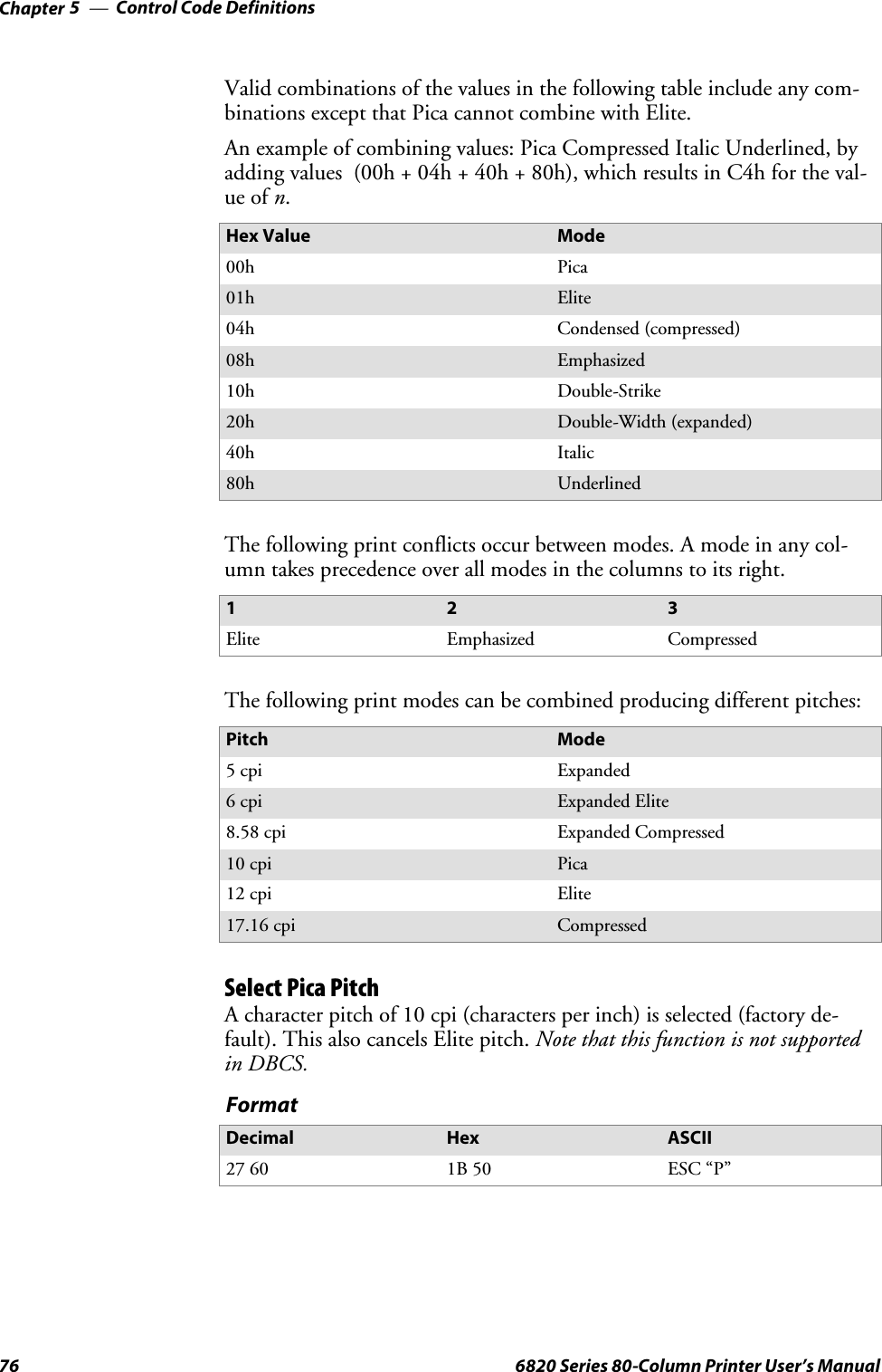
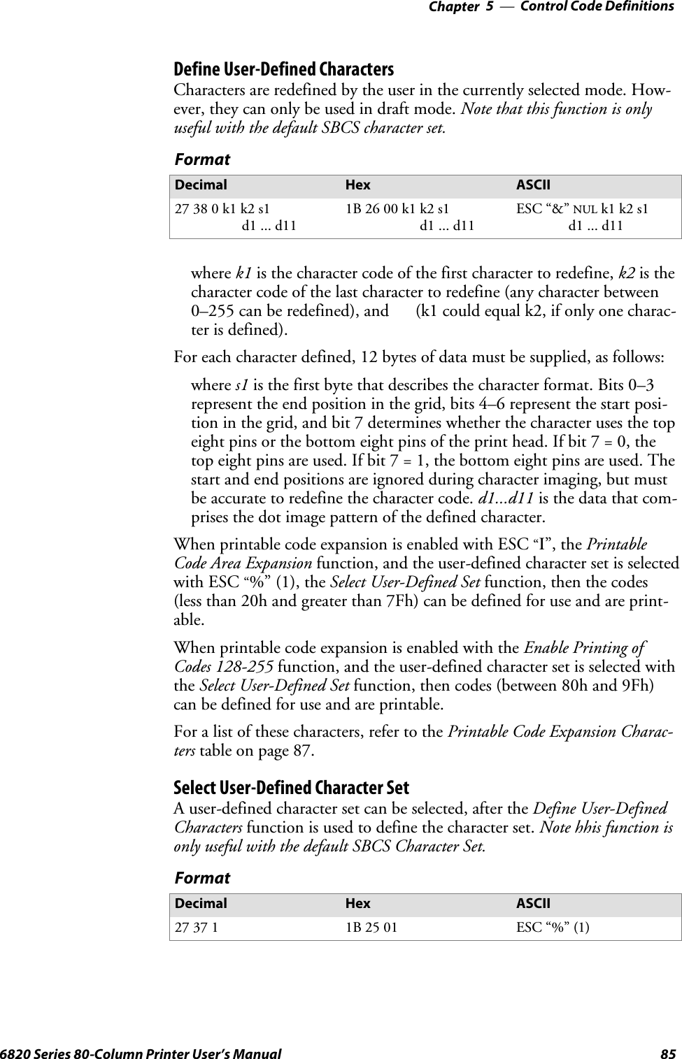
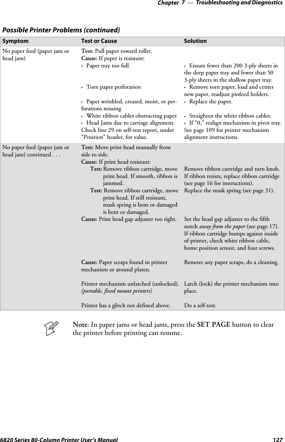
![Troubleshooting and Diagnostics—Chapter 71256820 Series 80-Column Printer User’s Manual21 A2D History22 Curr Low High Min Max Error Page Count23 24v: 024.00 023.21 023.91 023.21 024.51 027.21 00401 0002124 12v: 012.55 010.91 013.51 010.90 014.50 8.71 00401 0002125 Temp: 023 -020 055 -021 060 000 00401 0002126 Head Jam History27 Total Head Jams: 0018628 Home Command Direction Speed Step Temp Position Page29 Print Left Const 010 -010 01440 1234530 NPCP History31 Disc Addr Parity IFTS Seq CRC Frame Bind IPLDU32 12345 12345 12345 12345 12345 12345 12345 12345 1234533 IRDA History34 FramesOk BroadCasts CRC/TMO DISCARD35 rx 1234567890 1234567890 0123456789 000000000036 tx 1234567890 1234567890 0123456789 000000000037 HEAD DOT PATTERN38 Error Log39 PE HJ 12Vu 12Vo 24Vu 24Vo Home Temp OverC HeadS Fault ADErrEEErr40 Dlink Llink41 12345 12345 12345 12345 12345 12345 12345 12345 12345 12345 12345 123451234542 12345 12345 12345 12345 12345 12345 12345 12345 12345 12345 12345 123451234543 12345 12345 12345 12345 12345 12345 12345 12345 12345 12345Second Page of Self-TestPage 2 contains the print pattern used to diagnose printer mechanical be-havior. The pattern continuously prints the ASCII characters between 33and 126 decimal inclusive for the entire page, or until you cancel the printby pressing a button on the printer. An example of that rotating pattern isshown below.!”#$%’()*+,–./0123456789:;<=>?@ABCDEFGHIJKLMNOPQRSTUVWXYZ[\]^_’abcdefghijklmnopqrstuvwxyz{|}~!”#$%’()*+,–./0123456789:;<=>?@ABCDEFGHIJKLMNOPQRSTUVWXYZ[\]^_’abcdefghijklmnopqrstuvwxyz{|}~!”#$%’()*+,–./0123456789:;<=>?@ABCDEFGHIJKLMNOPQRSTUVWXYZ[\]^_’abcdefghijklmnopqrstuvwxyz{|}~!”#$%’()*+,–./0123456789:;<=>?@ABCDEFGHIJKLSelf-Test FailureIf a partial report generates and a printer error occurs during printing,refer to the table on the next page for troubleshooting help.If the printer does not generate a report:SThere may be a printer failure, refer to the troubleshooting table on thenext page for possible solutions.SThere may be a power failure, check the power source (internal battery,charge cable, or ac adaptor).](https://usermanual.wiki/Intermec-Technologies/BTS080-2/User-Guide-571475-Page-144.png)
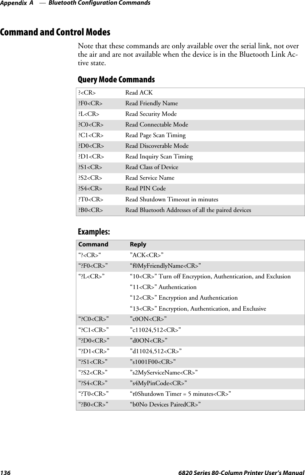
![Bluetooth Configuration CommandsAppendix —A134 6820 Series 80-Column Printer User’s ManualNotationNumbers are in decimal except:SNumbers with an “h” suffix are in hexadecimal.SNumbers with a “0x” prefix are in hexadecimal.SNumbers with a “b” suffix are in binary.CommandAll printable characters can be entered directly via the keyboard. Any non-printable characters are entered in binary data format.Binary data format is any non seven-bit ASCII data to transmit to themodule is encoded in the Internet percent notation. Any hex byte to trans-mit is preceded by the “%” sign and encoded in hex ASCII. To send thevalue 0xF5, the “%F5” bytes are transmitted. The “%”character is alwaystransmitted as “%25”. Thus, a Bluetooth address could transmit as“%00%E0%03%45%F4%6D”.Generic format:<command character><command type><command payload><CR><command character> is one character from the set: [A-Z]<command type> is one character for the set: [0-9]<command payload> is variable in length.<CR> is the command terminator.The <command payload> is formed from printable ASCII characters fromthe code range 0x20 to 0x7E.Codes outside of this range are escaped using the percent (%) characterfollowed by two hexadecimal digits.The percent character is always represented by the three characters: %25The command terminator is character code 0x13 (carriage return), or char-acter code 0x10 (line feed), or character codes 0x13, 0x10 (carriage return,line feed).An example command to set the friendly name to “Len’s 100% serial mod-ule”:F0Len’s 100%25 serial module<CR>Character codes outside of the range of 0x20 to 0x7E are ignored.When using percent (%) to form hexadecimal character codes there mustbe exactly two hex digits using characters: [0-9, A-F, a-f].Characters outside of this range cause the command to fail.Commands that fail return the four character sequence:NAK<CR>Commands that are accepted return the four character sequence:ACK<CR>](https://usermanual.wiki/Intermec-Technologies/BTS080-2/User-Guide-571475-Page-153.png)
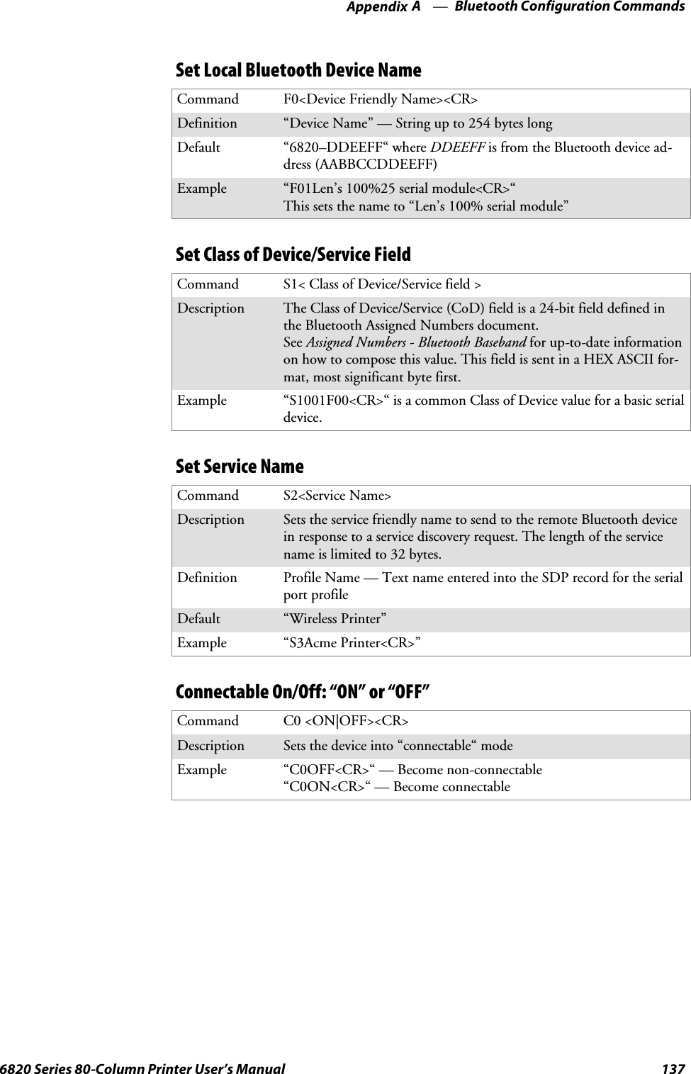
![Bluetooth Configuration CommandsAppendix —A1356820 Series 80-Column Printer User’s ManualCommands that return payload data use the format:<command character><command type><command payload><CR><command character> is one character from the set: [a-z]<command type> is one character for the set: [0-9]<command payload> is variable in length.<CR> is the command terminator.The command character is the “lower case” version of the local host com-mand.Operating ModesThemoduleinterfacehastwomodes:SBluetooth Link Active State: In this case the Serial Interface looks like araw serial port (TxD, RxD, CTS, etc. and GND). There is no intelli-gence in the Bluetooth module from the serial interface perspective.This mode does not support the command and control modes describedbelow.SBluetooth Link Inactive State: This mode exists when a Bluetooth linkis not existent: In this case, the serial interface looks like a serial portthat supports a number of command and control modes.Upon reset, the unit comes up in “Bluetooth Link Inactive State.” Afterthe first Bluetooth connection, the unit goes into “Bluetooth Link ActiveState.” It stays in this state until the link is lost because the Master shuts itdown or there is an out-of-range condition. At this point, it returns to the“Bluetooth Link Inactive State.”](https://usermanual.wiki/Intermec-Technologies/BTS080-2/User-Guide-571475-Page-154.png)