Intermec Technologies BTS080-2 6820 Printer User Manual legal
Intermec Technologies Corporation 6820 Printer legal
Users manual
578-100-026 Revision E Page 1 of 3
*578-100-026E*
*578-100-026E*
Compliance Statement Insert
Device Name: AC, DC Portable, Van, Wall Mount Printer Model Number: 6820
The responsible party for the compliance of this device is: Intermec Technologies Corporation
6001 36th Avenue West
Everett, WA 98203
USA
CAUTION: See users guide instructions for handling, charging, and replacing batteries. Failure to follow those instructions can result
in personal injury, fire, or battery explosion.
This product conforms to the following approvals. The user(s) of this product are cautioned to use accessories and peripherals
approved by Intermec Technologies Corporation. The use of accessories other than those recommended, or changes to this product that
are not approved by Intermec Technologies Corporation, may void the compliance of this product and may result in the loss of the users
authority to operate the equipment.
This device complies with Part 15 of the FCC Rules. Operation is subject to the following two conditions: (1) This device may not cause harmful
interference, and (2) this device must accept any interference received, including interference that may cause undesired operation.
FCC Digital Emissions Compliance
This equipment has been tested and found to comply with the limits for a Class B digital device, pursuant to Part 15 of the FCC Rules. These limits are
designed to provide reasonable protection against harmful interference in a residential installation. This equipment generates, uses and can radiate radio frequency
energy and, if not installed and used in accordance with the instructions, may cause harmful interference to radio communications. However, there is no guarantee
that interference will not occur in a particular installation. If this equipment does cause harmful interference to radio or television reception, which can be
determined by turning the equipment off and on, the user is encouraged to try to correct the interference by one or more of the following measures:
• Reorient or relocate the radio of television receiving antenna.
• Increase the separation between the computer equipment and receiver.
• Connect the equipment into an outlet on a circuit different from that to which the radio or television receiver is connected.
• Consult the dealer or an experienced radio television technician for help.
Canadian Digital Apparatus Compliance
This Class B digital apparatus meets all requirements of the Canadian Interference-Causing Equipment Regulations.
Cet appareil numérique de la classe B respecte toutes les exigences du Règlement sur le matériel brouilleur du Canada.
Radio Wave Exposure Information for Model 6820 Configurations with Bluetooth Radio
The Model 6820 Printer has been designed to comply with applicable safety requirements for exposure to radio waves. These requirements are based on
scientific guidelines that include safety margins designed to assure the safety of all persons, regardless of age and health.
The Model 6820 Printer with the Bluetooth option has been evaluated using the FCC Maximum Permissible Exposure (MPE) exposure guidelines when used
with the Intermec accessories supplied or designated for this product. Use of other accessories may not ensure compliance with FCC RF exposure guidelines.
Users should maintain 20 cm (approximately 8 inches) of clearance between themselves and the 6820 Printer when using the Bluetooth radio interface.

578-100-026 Revision E Page 2 of 3
*578-100-026E*
*578-100-026E*
DECLARATION OF CONFORMITY
(According to ISO/IEC Guide 22 and EN 45014)
THE PRODUCT HEREWITH COMPLIES WITH THE REQUIREMENTS OF :
THE LOW-VOLTAGE DIRECTIVE 73/23/EEC.
THE EMC DIRECTIVE 89/336/EEC.
THE R&TTE DIRECTIVE 1999/05/EC.
Manufacturer’s Name: European Representative:
Intermec Technologies Corporation Intermec International Incorporated
6001 36th Avenue West Sovereign House, Vastern Road
Everett, WA 98203 Reading, Berkshire
USA RG1 8BT England
Declares that the product listed below:
Product Type: ITE/Residential, Commercial, and Light Industrial
Product Name: 6820 DC Portable, Van, Wall Mount Printers
Model Number: 6820 Product Options: ALL
Beginning Serial Number: All Date Issued: August 10, 2005
Conforms to the following product specifications:
Safety: IEC 60950-1 / EN 60950-1
EMC: EN 55022 : 1998 / CISPR Publication 22 : 1997, Class B Limits and Methods
EN 55024 : 1998 (CISPR 24) Information Technology Equipment – Immunity Characteristics –
Limits and Methods of Measurement
EN 61000-4-2 : 1995 – Electrostatic Discharge
EN 61000-4-3 : 1995 – Radiated RF Field
EN 61000-4-4 : 1995 – Electrical Fast Transients
EN 61000-4-5 : 1995 – Voltage Surge
EN 61000-4-6 : 1996 – Conducted RF Field
EN 61000-4-11 : 1994 – Voltage Dips, Short Interruptions, and Variations
EN61000-3-2 : 1995 + A1 : 1998 + A2 : 1998 + A14 : 2000 – Harmonic Current Emissions
EN61000-3-3 : 1995 – Voltage Fluctuation and Flicker
Radio: ETSI EN 300 328
I, the undersigned, hereby declare that the equipment specified above conforms to the above Directive(s) and
Standard(s).
Company Official: Michael Abel Position: Vice President
Signature: Signed Copy on File Date: August 10, 2005
European Contact: Luc Van Geel, Intermec International Incorporated, Sovereign House, Vastern Road, Reading,
Berkshire, RG1 8BT England; Phone INT+44 118 987 9400; Fax INT+44 118 987 9401
Czech Republic Contact: Global AmeriTech Corporation, Rytirska 10, 110 00, Prague 1, Czech Republic;
Phone INT+420-224 210 493; Fax INT+420-224 211 729

578-100-026 Revision E Page 3 of 3
*578-100-026E*
*578-100-026E*
PROHLÁŠENÍ O DODRŽOVÁNÍ TECHNICKÝCH NAŘÍZENÍ
(V souladu se směrnicí 22 ISO/IEC a EN 45014)
STRÁNKA JEDNA Z JEDNÉ STRÁNKY
ZDE UVEDENÝ VÝROBEK SPLŇUJE POŽADAVKY:
SMĚRNICE 73/23/EEC PRO NÍZKONAPĚŤOVÁ ZAŘÍZENÍ
SMĚRNICE EMC 89/336/EEC
SMĚRNICE R&TTE 1999/05/EC
Jméno výrobce: Evropský zástupce:
Intermec Technologies Corporation Intermec International Incorporated
6001 36th Avenue West Sovereign House, Vastern Road
Everett, WA 98203, USA Reading, Berkshire
RG1 8BT England
prohlašuje, že níže uvedený výrobek:
Typ výrobku: Vybavení informační technologie/rezidenční, komerční a lehké průmyslové
Název výrobku: Model 6820 Kopírka
Číslo výrobku: Model 6820 Varianty: Všechny
Počáteční sériové číslo: Všechna Datum vydání: 10. Důstojný 2005
Splňuje následující parametry výrobku:
Bezpečnostní: IEC 60950-1 / EN 60950-1
EMC: EN 55022 : 1998 / CISPR vyhláška 22: 1997, Limity a metody třídy B
EN 55024: 1998 (CISPR 24) Vybavení informační technologie – charakteristiky odolnosti –
Limity a metody měření
EN 61000-4-2 : 1995 – Elektrostatický výboj
EN 61000-4-3 : 1995 – Vyzařované vysokofrekvenční pole
EN 61000-4-4: 1995 – Rychlé přechodové elektrické jevy
EN 61000-4-5: 1995 – Napěťový ráz
EN 61000-4-6: 1996 – Vedené vysokofrekvenční pole
EN 61000-4-8: 1995 – Magnetické pole
EN 61000-4-11: 1994 – Krátkodobé poklesy napětí, krátká přerušení a pomalé změny napětí
EN61000-3-2: 1995 + A1: 1998 + A1: 1998 + A1: 2000 – Vyzařované harmonické proudy
EN61000-3-3: 1994 – Kolísání napětí a blikání
Radio: ETSI EN 300 328
Já, níže podepsaný, tímto potvrzuji, že výše uvedené vybavení splňuje požadavky výše uvedených nařízení a
standardů.
Zástupce společnosti: Michael Abel Pozice: viceprezident
Podpis: Podepsaná kopie v evidenci Datum: 10. Důstojný 2005
Evropský kontakt: Intermec International Incorporated, Sovereign House, Vastern Road, Reading, Berkshire, RG1 8BT England;
Telefon: MEZIN. +44 118 987 9400; Fax MEZIN.+44 118 987 9401
Kontakt v České republice: Global AmeriTech Corporation, Rytířská 10, 110 00, Praha 1, Česká republika;
Telefon: MEZIN. +420-224 210 493; Fax MEZIN. +420-224 211 729

6820 Series
80-Column Printer
User's Manual
ii 6820 Series 80-Column Printer User’s Manual
Intermec Technologies Corporation
Corporate Headquarters Technical Communications Department
6001 36th Ave. W. 550 Second Street SE
Everett, WA 98203 Cedar Rapids, IA 52401
U.S.A. U.S.A.
www.intermec.com
The information contained herein is proprietary and is provided solely for the purpose of allowing customers
to operate and service Intermec-manufactured equipment and is not to be released, reproduced, or used for
any other purpose without written permission of Intermec.
Information and specifications contained in this document are subject to change without prior notice and do
not represent a commitment on the part of Intermec Technologies Corporation.
E1997-2005 by Intermec Technologies Corporation. All rights reserved.
The word Intermec, the Intermec logo, Norand, ArciTech, CrossBar, Data Collection Browser, dcBrowser,
Duratherm, EasyADC, EasyCoder, EasyLAN, Enterprise Wireless LAN, EZBuilder, Fingerprint, i-gistics,
INCA (under license), InterDriver, Intermec Printer Network Manager, IRL, JANUS, LabelShop, Mobile
Framework, MobileLAN, Nor*Ware, Pen*Key, Precision Print, PrintSet, RoutePower, SmartSystems, TE
2000, Trakker Antares, and Virtual Wedge are either trademarks or registered trademarks of Intermec
Technologies Corporation.
Throughout this manual, trademarked names may be used. Rather than put a trademark (™or ®) symbol in
every occurrence of a trademarked name, we state that we are using the names only in an editorial fashion,
and to the benefit of the trademark owner, with no intention of infringement.
There are U.S. and foreign patents pending.
Bluetooth is a trademark of Bluetooth SIG, Inc., U.S.A.
This product includes cryptographic software written by Eric Young (EAY@cryptsoft.com).

iii6820 Series 80-Column Printer User’s Manual
Document Change Record
This page records changes to this document. The document was originally released as Revision A.
Revision Date Description of Change
E04/2004 Updated printer paper specifications in Chapter 1, “Introduction.”
F08/2004 Merged technical reference information into user guide to create a user manual. Added
information about Bluetooth configuration, 600 Series Computers, 700 Series Comput-
ers, and the 6820 Configuration Utility application for Windows 2000 and Windows XP
operating systems.
G12/2004 Updated information for the Bluetooth shutdown timer. Added Appendix C, “Printer
Fonts Test Print Jobs” to provide sample test font print jobs.
H05/2005 Includes Bluetooth information for the wall mount printer.
J10/2005 Included CK60 Handheld Computer infomration.
iv 6820 Series 80-Column Printer User’s Manual
Contents
v6820 Series 80-Column Printer User’s Manual
Contents
Before You Begin xiii.............................................................
Safety Summary xiii.......................................................
Donotrepairoradjustalone xiii.......................................
First aid xiii.......................................................
Resuscitation xiii...................................................
Energized equipment xiii.............................................
Safety Icons xiv...........................................................
Global Services and Support xv..............................................
Warranty Information xv............................................
Web Support xv...................................................
Telephone Support xv...............................................
WhoShouldReadthisManual? xvi...........................................
Related Documents xvi.....................................................
Introduction
1...............................................................
About the Printers 2.............................................................
Battery Options 3.........................................................
Internal Battery 3..................................................
Vehicle Battery 3...................................................
Connectors 4............................................................
Fixed Mount Printer 4..............................................
Portable Printer 4..................................................
Wall Mount Printer 4...............................................
Control Panel 5..........................................................
Hinges on Printer Cover 6..................................................
Internal Power Module 6...................................................
Paper 7.................................................................
Material Breakdown 7...............................................
Caliber Breakdown 8................................................
Printer Dimensions 9......................................................
Wall Mount Printers 9..............................................
Fixed Mount Printers 9..............................................
Portable Printers 9..................................................
Remote Connections 9.....................................................
Reset Button 10..........................................................
Fixed Mount or Portable Printer 10....................................
Wall Mount Printer 10..............................................
Specifications 11................................................................
Inside Sales 12..................................................................
Operation
13.................................................................
Check List 14..................................................................
1
2
Contents
vi 6820 Series 80-Column Printer User’s Manual
Installing Internal Battery 15.......................................................
Installing the Ribbon Cartridge 16..................................................
Adjusting the Print Head Gap 17...................................................
Loading Paper Tray 18...........................................................
FixedMountandPortablePrinters 18.........................................
Wall Mount Printer 19....................................................
Loading the Flat Paper Tray 19........................................
Loading the Compact Paper Tray 19....................................
Loading Paper into Printer 20......................................................
Positioning the Paper 20...................................................
Adjusting the Pinfeed Holders 21.............................................
Setting the Paper 22.......................................................
Inserting Computer in Terminal Holder 23...........................................
Inserting a 4000 Series or a 62XX Computer 23.................................
Inserting a 61XX, a 600 Series, a 700 Series, or a CK60 Computer 24................
Maintenance
25..............................................................
Operating Guidelines 26..........................................................
General Cleaning 27.............................................................
Cleaning the Outside 27..........................................................
Cleaning the Inside 28...........................................................
Removing Old Ribbon Cartridge 29..........................................
Cleaning the Mask Spring 30................................................
Changing the Printer Settings 32...................................................
Protocol Selection Mode 32.................................................
Configuration Mode 32....................................................
Setting the Autofeed 32..............................................
Selecting the Bit Rate 33.............................................
Adjusting the Zero Print Option 33....................................
Using the 6820 Printer Configuration Utility
35............................
Font Modules 36................................................................
Connecting to the Printer 37.......................................................
3
4
Contents
vii6820 Series 80-Column Printer User’s Manual
Instructions for Windows 95 or Windows 98 38........................................
Installation 38...........................................................
Configuration File Support 38...............................................
Configuration Utility Operation 38...........................................
Starting the Program 39.............................................
Main Menu 39....................................................
Load Printer Configuration 40........................................
Modify Printer Configuration 43......................................
Save Printer Configuration 47.........................................
Save Defaults to Printer 50...........................................
Alpha Keyboard 52.................................................
Instructions for Windows 2000 or Windows XP 53.....................................
Installation 53...........................................................
Configuration Utility Operation 56...........................................
Starting the Program 56.............................................
Default Printer Settings 61...........................................
Error Messages 61..................................................
About the Configuration Utility 62.....................................
Bluetooth Adapter 62...............................................
Control Code Definitions
63.................................................
Control Code Definitions 64......................................................
Buffers 64...............................................................
I/O Buffer 64.....................................................
Print (image) Buffer 64..............................................
Special Notations 64......................................................
General Printer Control Functions 64.........................................
Backspace 64......................................................
Beeper 65........................................................
Cancel Line 65....................................................
Carriage Return 65.................................................
Delete 65.........................................................
Form Feed 65.....................................................
Select Half-Speed Printing 66.........................................
Cancel Half-Speed Printing 66........................................
Set Inactivity Time for Sleep Mode 66..................................
Line Feed 66......................................................
Perform Master Reset 67.............................................
Set Print Position (absolute) 67........................................
Set Print Position (relative) 68.........................................
Select Top-Down Printing 68.........................................
Select Bottom-Up Printing 68.........................................
Select Unidirectional Printing 68......................................
Cancel Unidirectional Printing 68......................................
Select Unidirectional (one line) Printing 69...............................
5
Contents
viii 6820 Series 80-Column Printer User’s Manual
Page Formatting Functions 69...............................................
Page Length 69....................................................
Line Spacing 70....................................................
Set Margins 71....................................................
Set Skip Over Perforation 72..........................................
Cancel Skip Over Perforation 72.......................................
Character Style and Text Mode Functions 72...................................
Select Condensed Mode (compressed) 72................................
Cancel Condensed Mode (compressed) 73...............................
Select Double-Strike Mode 73.........................................
Cancel Double-Strike Mode 73........................................
Select Double-Wide (expanded) Mode (one-line-only) 73....................
Cancel Double-Wide (expanded) Print (one-line-only) 74...................
Select Double-Wide (expanded) Mode 74................................
Cancel Double-Wide (expanded) Mode 74...............................
Select Elite Pitch 74................................................
Select Emphasized Mode 74..........................................
Cancel Emphasized Mode 75.........................................
Define Intercharacter Space 75........................................
Select Italic Mode 75................................................
Cancel Italic Mode 75...............................................
Master Select 75...................................................
Select Pica Pitch 76.................................................
Select Superscript Mode 77...........................................
Select Subscript Mode 77............................................
Cancel Subscript/Superscript Mode 77..................................
Select Underline Mode 77............................................
Cancel Underline Mode 77...........................................
Tabs and Tab Setting Functions 78...........................................
Horizontal Tabs 78.................................................
Vertical Tabs 79...................................................
Character Sets and User-Defined Functions 81..................................
Single Byte Character Sets 81.........................................
Double-Byte Character Sets 81........................................
Multi-Byte Character Sets 82.........................................
User Defined Characters 84..........................................
Graphics Functions 89.....................................................
Eight-Pin Graphics Modes 89.........................................
Nine-Pin Graphics Modes 91.........................................
Page Layout for Fanfold Paper 93...................................................
Printable Area 93.........................................................
Paper End Detection 94....................................................
Bluetooth Adapter
95........................................................
About the Bluetooth Adapter 96....................................................
Bluetooth Adapter Indicators 97.............................................
700 Series or CK60 Handheld Computer to 6820 Pass Through 97............
700 Series or CK60 Handheld Computer to Bluetooth Module Communication
Interface 97................................................
6
Contents
ix6820 Series 80-Column Printer User’s Manual
Bluetooth Adapter Power Management Flow 98.................................
Radio Power On/Off Mechanism 98..........................................
Security 99..............................................................
Persistent Storage 99......................................................
System Behavior/Software Considerations 99....................................
Remote Configuration 100.................................................
Bluetooth Performance 100.................................................
Diagnostics Capabilities 101.......................................................
RadioSelfTest 101.......................................................
Applications 102................................................................
System Qualification 103.........................................................
Operation Resilience 103...................................................
Environmental Specifications 103............................................
Temperature 103...................................................
Altitude 103......................................................
Vibration 103.....................................................
Unpackaged Drop 103..............................................
Terminal Inspection 103.............................................
Safety/Regulatory/Agency Requirements 104....................................
Default Configuration 105........................................................
Troubleshooting and Diagnostics
107......................................
Checking the Power Source 108....................................................
Self-Test Failure 108.............................................................
Printer Mechanism Alignment 109..................................................
Communications or Host Computer 110.............................................
Communications Pin-Out Configurations 111.........................................
Troubleshooting 117.............................................................
Verifying the Printer Components 117........................................
Power Source Verification 117........................................
Printer Verification 117..............................................
Communications / Host Computer Verification 118.......................
Error Handling 118.......................................................
Run-Time Errors 118...............................................
Power-On Self-Test (POST) 119......................................
POST Errors 119..................................................
Fatal Errors 120...................................................
7
Contents
x 6820 Series 80-Column Printer User’s Manual
Self-Test Function Descriptions 121..........................................
Boot Block Program Verification 121...................................
Control Program Verification 121......................................
Font Module Verification 121.........................................
A2D Check 121...................................................
Nonvolatile Diagnostic Memory Verification 121..........................
Nonvolatile Diagnostic Memory Update 121.............................
Detailed Printer Self-Test 122...............................................
Initiating Self-Test 122..............................................
Terminating Self-Test 122...........................................
Self-Test Report 122................................................
First Page of Self-Test 123............................................
Sample First Page of Self-Test 124.....................................
Second Page of Self-Test 125..........................................
Self-Test Failure 125................................................
Miscellaneous Troubleshooting Tips 126.......................................
Compatibility Issues 128...................................................
Diagnostic Information 128.......................................................
Nonvolatile Flash Storage 128...............................................
Updating Diagnostic Information 128.........................................
Accessing Diagnostic Information 129.........................................
Bluetooth Configuration Commands
133...................................
Notation 134..................................................................
Command 134.................................................................
Operating Modes 135.....................................................
Command and Control Modes 136...........................................
Query Mode Commands 136.........................................
Set Local Bluetooth Device Name 137..................................
Set Class of Device/Service Field 137...................................
Set Service Name 137...............................................
Connectable On/Off: “ON” or “OFF” 137..............................
Specify Page Scan Timing 138........................................
Enable Discoverable 138.............................................
Specify Inquiry Scan Timing 138......................................
Set Encryption/Authentication: “PIN CODE” 138........................
Manage Security Modes 139................................................
Read Module Version 139............................................
Read Local Device Address 140........................................
Set Shutdown Timing 140...........................................
Clear Link Key Table 140............................................
Web Links 140.................................................................
Cross-Reference Tables
141..................................................
Control Codes and Escape Sequences 142.............................................
A
B
Contents
xi6820 Series 80-Column Printer User’s Manual
Single Character Control Code Definitions 149........................................
Escape Sequence Quick Reference 150...............................................
Factory-Installed Printer Defaults 152................................................
PrinterFontTestJobs
155...................................................
Big 5 Traditional Chinese Character Set 156..........................................
Simplified Chinese Character Set 156................................................
IBM 437 Codepage Character Set 156...............................................
Japanese (Shift JIS) Character Set 157................................................
Korean Character Set 157.........................................................
International Character Set 157....................................................
Index
Control Codes 160..............................................................
General Index 163...............................................................
Files Index 169.................................................................
C
I
Contents
xii 6820 Series 80-Column Printer User’s Manual
Before You Begin
xiii6820 Series 80-Column Printer User’s Manual
Before You Begin
This section provides you with safety information, technical support
information, and sources for additional product information.
Safety Summary
Your safety is extremely important. Read and follow all warnings and
cautions in this document before handling and operating Intermec
equipment. You can be seriously injured, and equipment and data can be
damaged if you do not follow the safety warnings and cautions.
Donotrepairoradjustalone
Do not repair or adjust energized equipment alone under any
circumstances. Someone capable of providing first aid must always be
present for your safety.
First aid
Always obtain first aid or medical attention immediately after an injury.
Never neglect an injury, no matter how slight it seems.
Resuscitation
Begin resuscitation immediately if someone is injured and stops breathing.
Any delay could result in death. To work on or near high voltage, you
should be familiar with approved industrial first aid methods.
Energized equipment
Never work on energized equipment unless authorized by a responsible
authority. Energized electrical equipment is dangerous. Electrical shock
from energized equipment can cause death. If you must perform
authorized emergency work on energized equipment, be sure that you
comply strictly with approved safety regulations.

Before You Begin
xiv 6820 Series 80-Column Printer User’s Manual
Safety Icons
This section explains how to identify and understand dangers, warnings,
cautions, and notes that are in this manual. You may also see icons that tell
you when to follow ESD procedures and when to take special precautions
for handling optical parts.
A warning alerts you of an operating procedure, practice, condition,
or statement that must be strictly observed to avoid death or serious
injury to the persons working on the equipment.
Avertissement: Un avertissement vous avertit d’une procédure de
fonctionnement, d’une méthode, d’un état ou d’un rapport qui doit
être strictement respecté pour éviterl’occurrencedemortoude
blessures graves aux personnes manupulant l’équipement.
A caution alerts you to an operating procedure, practice, condition, or
statement that must be strictly observed to prevent equipment damage
or destruction, or corruption or loss of data.
Attention: Une précaution vous avertit d’une procédure de
fonctionnement, d’une méthode, d’un état ou d’un rapport qui doit
être strictement respecté pour empêcher l’endommagement ou la
destruction de l’équipement, ou l’altération ou la perte de données.
Note: Notes either provide extra information about a topic or contain
special instructions for handling a particular condition or set of
circumstances.

Before You Begin
xv6820 Series 80-Column Printer User’s Manual
Global Services and Support
Warranty Information
To understand the warranty for your Intermec product, visit the Intermec
web site at www.intermec.com and click Service & Support.TheIntermec
Global Sales & Service page appears. From the Service & Support menu,
move your pointer over Support,andthenclickWarranty.
Disclaimerofwarranties:Thesamplecodeincludedinthisdocumentis
presented for reference only. The code does not necessarily represent
complete, tested programs. The code is provided “as is with all faults.” All
warranties are expressly disclaimed, including the implied warranties of
merchantability and fitness for a particular purpose.
Web Support
Visit the Intermec web site at www.intermec.com to download our current
manuals in PDF format. To order printed versions of the Intermec
manuals, contact your local Intermec representative or distributor.
Visit the Intermec technical knowledge base (Knowledge Central) at
intermec.custhelp.com to review technical information or to request
technical support for your Intermec product.
Telephone Support
These services are available from Intermec Technologies Corporation.
Service Description
In the U.S.A. and Canada
call 1-800-755-5505
and choose this option
Factory Repair and
On-site Repair
Request a return authorization
number for authorized service
center repair, or request an
on-site repair technician.
1
Technical Support Get technical support on your
Intermec product.
2
Service Contract
Status
Inquire about an existing
contract, renew a contract, or ask
invoicing questions.
3
Schedule Site Surveys
or Installations
Schedule a site survey, or request
a product or system installation.
4
Ordering Products Talk to sales administration,
place an order, or check the
status of your order.
5
Outside the U.S.A. and Canada, contact your local Intermec
representative. To search for your local representative, from the Intermec
web site, click Contact.

Before You Begin
xvi 6820 Series 80-Column Printer User’s Manual
WhoShouldReadthisManual?
This manual provides you with information about the features of the 6820
Series 80-Column Printer, how to install, configure, operate, maintain,
access the programming capability, and troubleshoot the printer.
Related Documents
This table contains a list of related Intermec documents and their part
numbers.
Document Title Part Number
6820 Printer Terminal Holder Upgrade Instructions 962-018-011
6820 Printer Installation Instructions 962-018-016
The Intermec web site at www.intermec.com contains our documents that
you can download in PDF format.
To order printed versions of the Intermec manuals, contact your local
Intermec representative or distributor.

16820 Series 80-Column Printer User’s Manual
Introduction
1
The 6820 Printer is used in the route accounting industry to produce
high-quality customer invoices, receipts, load reports, transfers, and other
documents. A unique “sleep” feature saves energy when the printer is not
printing, eliminating the ON/OFF switch. Data input is normally pro-
vided by hand-held or mobile computers.

IntroductionChapter —1
2 6820 Series 80-Column Printer User’s Manual
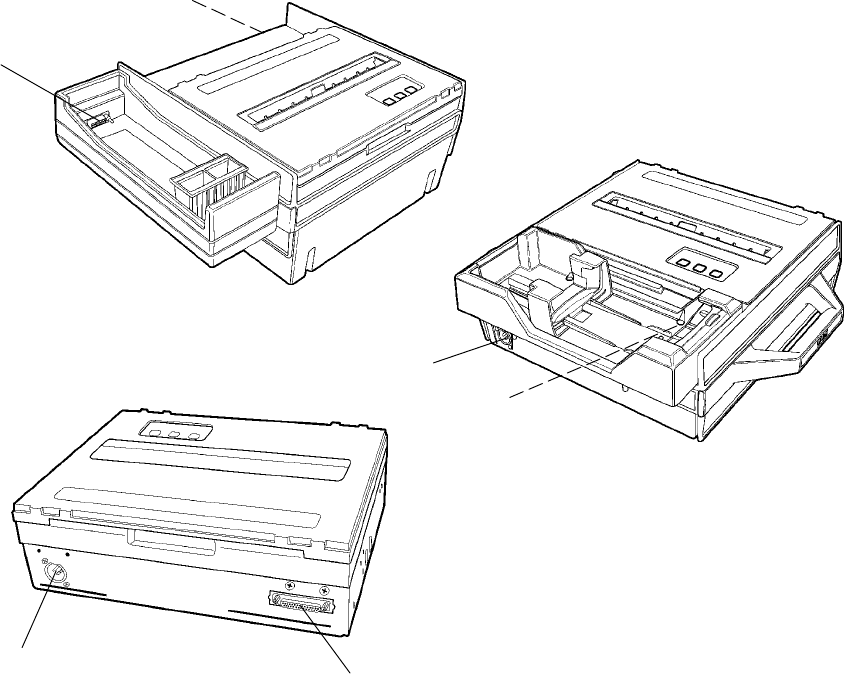
About the Printers
SFixed Mount Printer
The fixed mount printer is mounted in motor vehicles or used in a
settlement room. The terminal holder may be mounted on the printer
or a remote dock can connect to the side of the printer. A deep paper
tray, which holds up to 200 3-ply forms (about 2” or 5 cm thick) is un-
dertheprintermechanism.
SPortable Printer
The portable printer has a handle so that you can carry it. An optional
internal battery permits operation without the use of an external power
source. The terminal holder is an integral part of this printer. A shallow
paper tray, which holds up to 50 3-ply forms (about an inch or 2.5
centimeters thick) is under the printer mechanism.
SWall Mount Printer
The wall mount printer hangs on a mounting plate secured to a wall.
Computers communicate with this printer through the remote terminal
holder, remote dock, or vehicle dock. With no internal paper tray, pa-
per is loaded from a separate paper tray (holds up to 2.5” or 6 cm of pa-
per) or a box. The printer mechanism is permanently attached.
Wall Mount Printer
(with mounting plate and flat paper tray)
Fixed Mount Printer
(with 4000 Series/62XX Terminal Holder)
Portable Printer
(with 61XX Terminal Holder)
Introduction—Chapter 1
36820 Series 80-Column Printer User’s Manual
Battery Options
The following battery options are available for the 6820 Printers. See “In-
side Sales” for ordering information and part numbers
Internal Battery
This battery (P/N: 317-075-001) allows the portable printer and some
fixed mount printers to operate independently of other power sources.
Vehicle Battery
A power cable provides power to the printer through a cable permanently
installed in the vehicle.
IntroductionChapter —1
4 6820 Series 80-Column Printer User’s Manual
Connectors
Each printer has a dc power jack that connects the printer to a power
source, such as the vehicle battery or an external power supply.
Each printer communicates with a mobile computer through the 25-pin
data communications connector (wall mount printer) or mobile computer
socket (in terminal holder, remote terminal holder, or vehicle dock).
Fixed Mount Printer
The dc power connector is on the bottom rear of the printer behind the
printer terminal holder. The data communications socket is in either the
printerterminalholderoraseparatevehicledock.
Portable Printer
The dc power connector is on the side of the printer beneath the printer
terminal holder. The data communications socket is either in the printer
terminal holder or a separate vehicle dock.
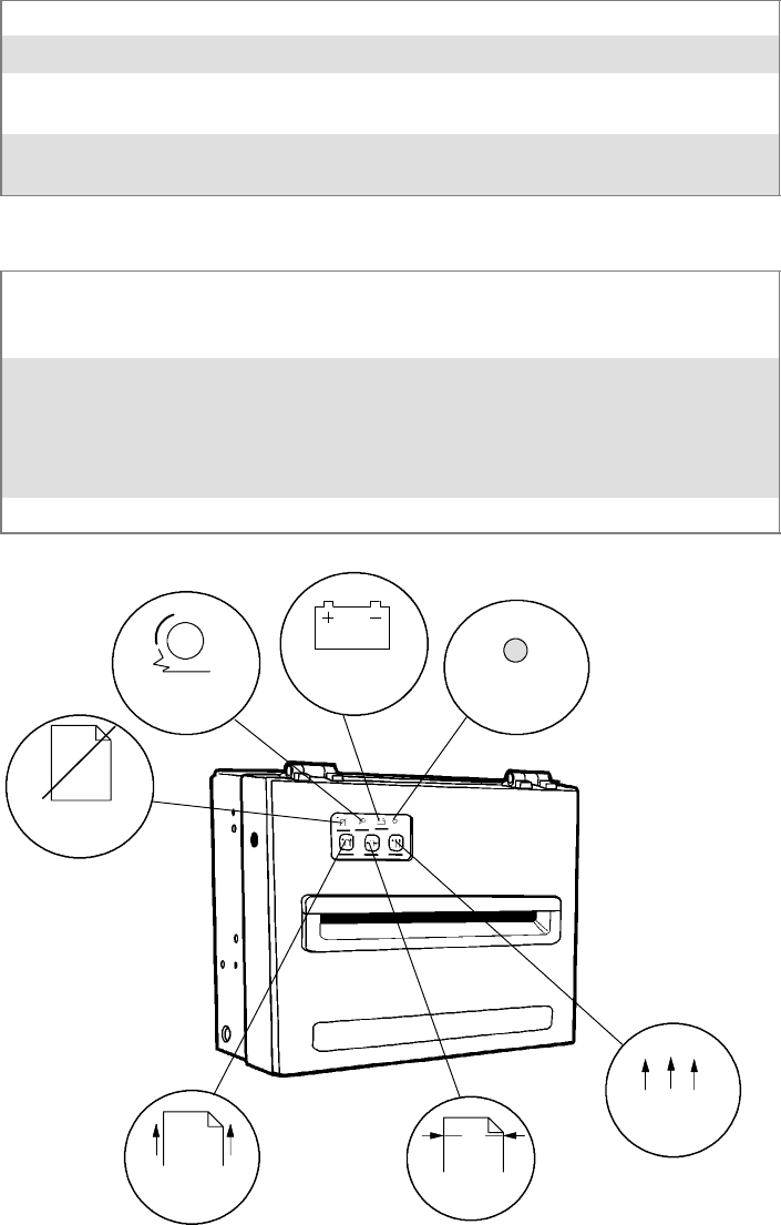
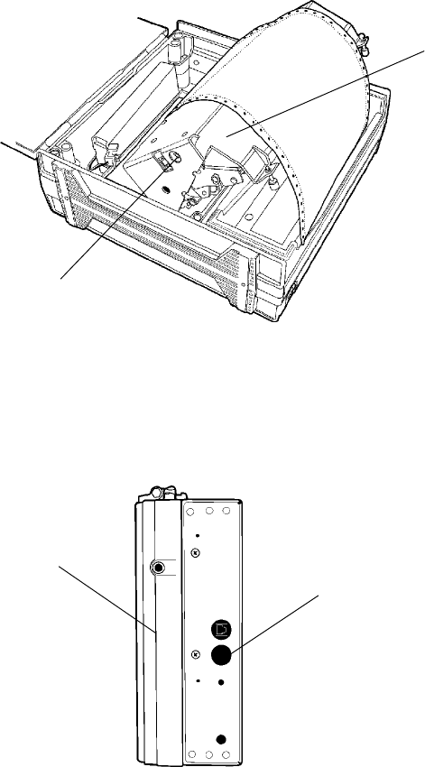
Wall Mount Printer
The dc power connector is on the bottom left of the printer. The data
communications connector (25-pin socket) is on the bottom right.
Data communications
connector
DC power
connector
Wall Mount Printer
DC power
connector
DC power
connector
Portable Printer
Mobile computer
socket
Mobile computer
socket
Fixed Mount Printer
Introduction—Chapter 1
56820 Series 80-Column Printer User’s Manual
Control Panel
The printer control panel has four indicators in the top row and three but-
tons in the bottom row. Three indicators blink when there is a problem.
The three buttons adjust and align the paper.
Indicators
PAPER OUT The printer is out of paper.
HEAD JAM The print head is jammed and cannot move.
LOW BATT The internal battery voltage, the vehicle battery voltage, or the power
module voltage is too low.
Power This stays lit while the printer is in active mode, or awake. When the
printer is in sleep mode, or without power, this is dark.
Buttons
FORM FEED Press this button to feed the paper into the printer mechanism or
when the printer should advance to the next form. If the printer ran
out of paper, press this button to initiate automatic paper loading.
SET PAGE Press this button to signal the beginning of the page to the printer
after you have made the appropriate paper adjustments; or to set the
linefeed counter to zero and move the print head to its home posi-
tion. In “Paper Out” conditions, press this button to clear the Paper Out
error before printing can resume.
LINE FEED Press this button to adjust the top of the paper to the next line.
SET PAGE
FORM FEED
PAPER OUT
HEAD JAM
LOW BATT Power
LINE FEED
IntroductionChapter —1
6 6820 Series 80-Column Printer User’s Manual
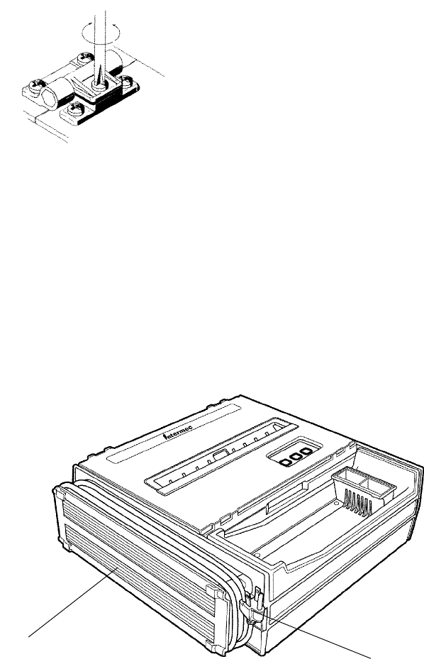
Hinges on Printer Cover
All printer covers are hinged to the printer. These hinges have a tension
screw (turn clockwise to tighten, turn counterclockwise to loosen), should
you need to adjust them.
Internal Power Module
The alternating current (ac) power module, or the ac foot, is available for
fixedmountandportableprinters—notforwallmountprinters—and
allows for ac operation. The ac foot is installed at the factory and is not an
add-on option.
Insert the power cord connector into the ac foot connector in the printer;
then plug the cord into an ac outlet. This power cord can wrap around the
ac foot when not in use.
AC foot
Plug on power cord
(goes to ac outlet)
Introduction—Chapter 1
76820 Series 80-Column Printer User’s Manual
Paper
Use of paper that matches the following specifications ensures
optimum 6820 performance. Variation from these specifications, use
of aged paper, or use of paper exposed to elements such as dirt or
humidity may cause printing problems.
The printer works with 1–3 ply carbonless paper that is single-edge glued
and designed for sprocket feed. Standard paper size is 8.5 x 11” or 8.5 x
12” (241 x 305 mm international). Use 3-ply forms up to a maximum of
0.009 inch (0.23 mm) thick.
A soft, flexible, rubber type cement applied to one perforation strip only is
preferred. The resultant lamination should wrap around a 1-1/4 inch di-
ameter roll without curl or wrinkle.
Material Breakdown
The following tables show the material broken down per ply:
14# CBF (Carbonless Back and Front)
Target Under Over
Basis Weight 14# 13.3 14.7
Caliper 2.9 2.6 3.2
Moisture 5.0 4.0 6.0
Smoothness (RS) 165 110 230
Smoothness (CB) 270 220 320
Brightness (Wht) 88 86 90
Colors available: White, Canary, Pink, Goldenrod, Blue, Green
15# CF (Carbonless Front)
Target Under Over
Basis Weight 15# 14.43 15.8
Caliper 3.0 2.5 3.2
Moisture 5.0 4.0 6.0
Smoothness (RS) 140 100 180
Smoothness (CF) 140 100 180
Brightness (Wht) 85 84 86
Colors available: White, Canary, Pink, Goldenrod, Blue, Green

IntroductionChapter —1
8 6820 Series 80-Column Printer User’s Manual
16# CB (Carbonless Back)
Target Under Over
Basis Weight 16# 15.2 16.8
Caliper 3.3 2.8 3.8
Moisture 5.7 4.2 6.7
Smoothness (RS) 180 120 270
Smoothness (CB) 270 220 320
Brightness (Wht) 86 84 88
Opacity (Wht) 81 78.5 82
20# OCR Laser Bond
Target Under Over
Basis Weight 20# 15.2 16.8
Caliper 4.0 3.8 4.2
Moisture 3.8 4.7 5.0
Smoothness 140 100 170
Brightness (Wht) 94 82 N/A*
Opacity (Wht) 85 84 N/A
* Not Applicable
Caliber Breakdown
The following information show the caliber of forms broken down per ply:
1-Ply (20#)
Targeted: 4.0
Maximum: 4.2
2-Ply (15# and 16#)
Targeted: 6.3
Maximum: 7.0
3-Ply (14#, 15#, and 16#)
Targeted: 9.2
Maximum: 10.2

Introduction—Chapter 1
96820 Series 80-Column Printer User’s Manual
Printer Dimensions
Below are the three most common printer configurations:
Wall Mount Printers
See the 6820 Printer Installation Instructions P/N: 962-018-016 for Wall
Mount assembly dimensions. Below are the width, height, and depth di-
mensions for the Wall Mount Printer.
Width Length Depth
13.25” 10.5” 4.5”
(33.7 cm) (26.7 cm) (11.4 cm)
Fixed Mount Printers
The base of the Fixed Mount Printer is 12.75” (32.5 cm) wide by 14”
(35.5 cm) front to back. The upper portion varies according to the config-
urationsshowninthefollowingtable.
Fixed Mount Printer Dimensions
Configuration (with deep paper tray) Width Length Depth
with 61XX Holder Side Mount
20.25”
(51.4 cm)
14.5”
(36.8 cm)
7.5”
(19.1 cm)
with 4000 Sesries, 62XX, 600 Series, 700 Series, or CK60
Holder Side Mount
18.5”
(47.0 cm)
14.5”
(36.8 cm)
8.0”
(20.3 cm)
with 61XX Holder Top Mount
16.75”
(42.5 cm)
16.75”
(42.6 cm)
7.5”
(19.1 cm)
with 4000 Series, 62XX, 600 Series, 700 Series, or CK60
Holder Top Mount
15.0”
(38.1 cm)
16.75”
(42.6 cm)
8.0”
(20.3 cm)
Portable Printers
The Portable Printer may come with a handle, an ac foot, or with a termi-
nal holder top mount. Note the ac foot adds 2.5” (6.35 cm) to the width.
Portable Printer Dimensions
Configuration Width Length Depth
with handle, 61XX Holder Top Mount, and Deep Paper Tray 16.5”
(41.9 cm)
16.75”
(42.6 cm)
8.0”
(20.3 cm)
with handle, 61XX Holder Top Mount, and Shallow Paper Tray 16.75”
(42.5 cm)
16.75”
(42.6 cm)
7.5”
(19.1 cm)
with handle, 4000 Series, 62XX, 600 Series, 700 Series, or CK60
Holder Top Mount, and Deep Paper Tray
15.0”
(38.1 cm)
16.75”
(42.6 cm)
8.0”
(20.3 cm)
with handle, 4000 Series, 62XX, 600 Series, or 700 Series, or CK60
Holder Top Mount or Fill Plate, and Shallow Paper Tray
16.5”
(41.9 cm)
15.0”
(38.1 cm)
5.13”
(13.0 cm)
Remote Connections
A printer and a computer, using the supplied serial cable, can operate
while up to 30 feet (9 meters) apart.
IntroductionChapter —1
10 6820 Series 80-Column Printer User’s Manual
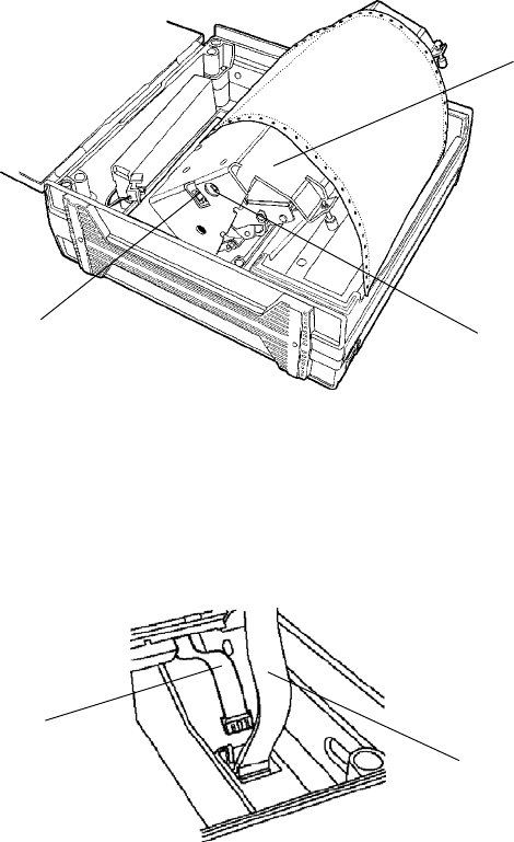
Reset Button
Each printer has a reset button that cold-boots the printer.
Fixed Mount or Portable Printer
Both the fixed mount printer and the portable printer have the reset but-
ton on the left-hand side of the raised printer mechanism. See the follow-
ing illustration for the location of the reset button.
Reset
button
Printer
mechanism
(raised)
Wall Mount Printer
The wall mount printer has the reset button on the right hand side of the
printer case.
Reset
button
Front of
printer
Introduction—Chapter 1
116820 Series 80-Column Printer User’s Manual
Specifications
Note: Various print fonts do affect the print speed.
Print Speed: 230 cps
Weight:
Fixed Mount Printer: 14.41 lbs (6.55 kg)
Portable Printer:
with 4000 or 61XX Terminal
Holder:
12.75 lbs (5.80 kg)
with 62XX. 600 Series, 700
Series, or CK60 Terminal
Holder:
12.25 lbs (5.67 kg)
Wall Mount Printer: 10.00 lbs (4.54 kg)
Mounting plate: 4.25 lbs (1.93 kg)
Flat paper tray: 5.40 lbs (2.45 kg)
Compact paper tray: 4.50 lbs (2.05 kg)
Temperature:
DC Operating: –4_to 140_F (–20_to 60_C)
AC Operating: –4_to 113_F (–20_to 45_C)
Storage: –22_to 158_F (–30_to 70_C)
Humidity:
Operating: 10 to 85% noncondensing
Storage: 5 to 95% noncondensing
Altitude:
Operating: –100 to 5000 meters
Storage: 15,000 meters
Electrical:
Voltage: 13.8 volts dc (nominal)
Current: 1 mA (sleep mode — no charge); 3.5 amps
(average while charging internal battery)
Vibration: 1.5 Gs RMS for six hours
ESD: 15 kV noncontact and 8 kV contact
Battery:
Shelf life: 1year@77_F(25_C)
2.3 amperes-hour
12 volt lead acid
(order batteries through Inside Sales)
Note: Battery goes dead within two weeks if connected to the printer and
with no external charge source.

IntroductionChapter —1
12 6820 Series 80-Column Printer User’s Manual
Inside Sales
Contact Inside Sales at 1-800-255-6292 for these supplies:
Cables:
4’ power cable P/N: 226-215-001
8’ Battery cable P/N: 206-875-002
16’ Battery cable P/N: 206-875-006
22’ Battery cable P/N: 206-875-009
”Y” power cable P/N: 226-325-001
Internal battery: P/N: 317-075-001
Cleaning solutions:
MICRO-CLEAN II P/N: 901-438-001
Guide Shaft Cleaner P/N: 901-439-001
Paper:
1-ply: P/N: 816-027-111
2-ply: P/N: 816-027-012
3-ply: P/N: 816-027-013
Ribbon cartridges with:
Black ribbon: P/N: 805-060-001
Purple ribbon: P/N: 805-060-002

136820 Series 80-Column Printer User’s Manual
2Operation
This chapter provides instructions how to set up the 6820 Printer for the
first time.

OperationChapter —2
14 6820 Series 80-Column Printer User’s Manual
Check List
Make sure the following tasks are done:
SPrinter is unpacked.
SFoam blocks are removed from around the printer. Save the box and
packaging materials for future use, such as servicing, relocations, etc.
STwist tie is removed from the print head.
SPower cable is hooked up to the vehicle battery or power source.
SPrinter is mounted in the vehicle.
The following tasks must be done. Specific instructions for these tasks are
described on the pages given:
1Connect the battery (page 15).
2Install the ribbon cartridge (page 16).
3Load the paper into the paper tray (page 18) and into the printer (sever-
al steps starting on page 20).
4Insertthemobilecomputer(page23).
Note: Complete these tasks before starting any printer operations.
Operation—Chapter 2
156820 Series 80-Column Printer User’s Manual
Installing Internal Battery
The optional internal battery (sold separately — see “Inside Sales” in Chapter
1 for ordering information and part number) is primarily for portable print-
ers; not wall mount printers. Thebatterycangoinsomefixedmountprint-
ers via a cable and a factory-installed adapter.
The printer battery recharges automatically when the printer is connected
to an external power source via power cable. For most installations, the
external power source is passed through the printer to the mobile comput-
er. The printer battery does not providechargetothecomputer.
Note: Remove the printer battery when storing a printer for over 30 days.
After storage, reinstall the battery and connect the printer to an external
power source for at least two hours, to recharge the battery.
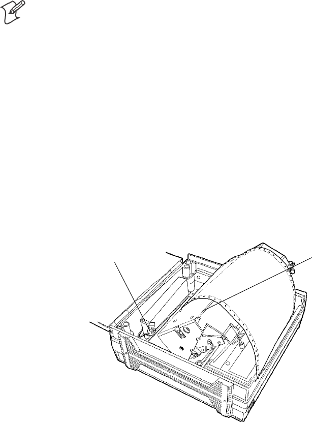
1Unlatch and open the printer mechanism.
2Lower the battery into the rear of the printer case, as shown.
3Attach the battery cable to the battery.
4Push the battery down and back under the back edge of the case. The
battery should snap into place.
5Close and latch the mechanism.
Battery
Battery
cable
Printer mechanism
(raised)
Latches or
rubber bumpers
OperationChapter —2
16 6820 Series 80-Column Printer User’s Manual
Installing the Ribbon Cartridge
Ensure there is a ribbon cartridge (sold separately — see “Inside Sales” in
Chapter 1 for ordering information and part number) in the printer before
you print and that the ribbon is fully seated (cartridge makes a distinct
“snap” or “click”) with the visible portion of the ribbon straight and even.
1Turn the ribbon advance knob (in the direction of the raised arrows) to
remove any slack in the ribbon.
2Squeeze the ribbon cartridge locking tab into the cartridge, then lower
the cartridge over the print head.
3Lower the tab side of the cartridge until it clicks.
4Release the tab and press down on the arrow to fully seat the ribbon car-
tridge (tab clicks outward).
5Turn the ribbon advance knob (follow raised arrows) to align the ribbon
in the front of the print head.
Ribbon
Locking tab
Advance
knob
Tightens
ribbon
Operation—Chapter 2
176820 Series 80-Column Printer User’s Manual
Adjusting the Print Head Gap
The head gap adjuster is near the printer mechanism on the side opposite
the green thumb wheel. The print head adjuster has five notches between
the print head and the platen for different paper thicknesses.
Verify the thickness of the paper loaded into the printer.
SIf you are using single-sheet forms, set the head gap adjuster to the third
notch away from the paper.
SIf you are using multiple-sheet forms (2-ply or 3-ply), set the head gap
adjuster to the fourth notch away from the paper.
SIf you experience frequent head jams, set the head gap adjuster to the
fifth notch away from the paper. This may stop the head jams.
SIf the 2-ply and 3-ply paper have light printing, setting the gap adjuster
to a closer setting will darken the print.
Note the print head adjuster is set on the third notch.
OperationChapter —2
18 6820 Series 80-Column Printer User’s Manual
Loading Paper Tray
Note: Do not exceed the recommended amounts of paper quantity or
thickness. When loading multiple-sheet paper, be sure to have the original
faced up, with the leading edge towards the rear of the printer.
FixedMountandPortablePrinters
1Unlatch and raise the printer mechanism.
2Lower a stack of paper, with the original faced up, into the paper tray
undertheprintermechanism.
SThe fixed mount printer holds up to 200 3-ply forms (about 2” or 5
cm thick).
STheportableprinterholdsupto503-plyforms(aboutaninchor
2.5 cm thick).
3Pull the top form out and over the rear of the printer mechanism. Low-
er and latch the printer mechanism.
Printer mechanism
(raised)
Paper tray
(beneath printer
mechanism)
Operation—Chapter 2
196820 Series 80-Column Printer User’s Manual
Wall Mount Printer
The wall mount printer can load paper from either an optional flat paper
tray or an optional compact paper tray.
Loading the Flat Paper Tray
If you have a flat paper tray attached to the wall mount printer, hold a
stack of paper, upto2.5inches(6cm)thick,with the original facing you,
and lay the stack flat into the tray. Pull the top form out to load into the
printer.
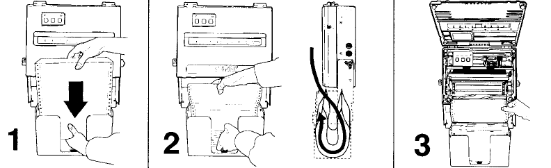
Loading the Compact Paper Tray
If you have a compact paper tray attached to the wall mount printer, do
the following to load paper into that tray:
1With the original facing you, hold a stack of paper, upto2.5inches(6cm)
thick, vertically over the compact paper tray.
2Simultaneously lower the paper into the compact paper tray and pull up
the bottom end of the paper until the entire stack fits, like a “U,” inside
the compact paper tray.
3Pull the top form out to load into the printer.
The compact paper tray is filled in this illustration
OperationChapter —2
20 6820 Series 80-Column Printer User’s Manual
Loading Paper into Printer
CAUTION: Follow these steps to load the paper into the printer, or
paper jams may occur.
Paper for the 6820 Printer has perforated strips that fit onto the pinfeed
holder pins, guiding the paper into the printer. This paper is sold separate-
ly in 1-, 2-, or 3-ply forms. See “Inside Sales” in Chapter 1 for ordering
information and part numbers.
Positioning the Paper
1Open the pinfeed holders outward.
2Take the top edge of the sheet of paper and position it, original side fac-
ing down, over the pinfeed holder pins.
3Align the first few holes of the paper, on each side of the paper, onto the
pinfeed holder pins.
4Close the pinfeed holders.
5Raise the paper bail.
Note: Go to the next page to adjust the pinfeed holders.
Operation—Chapter 2
216820 Series 80-Column Printer User’s Manual
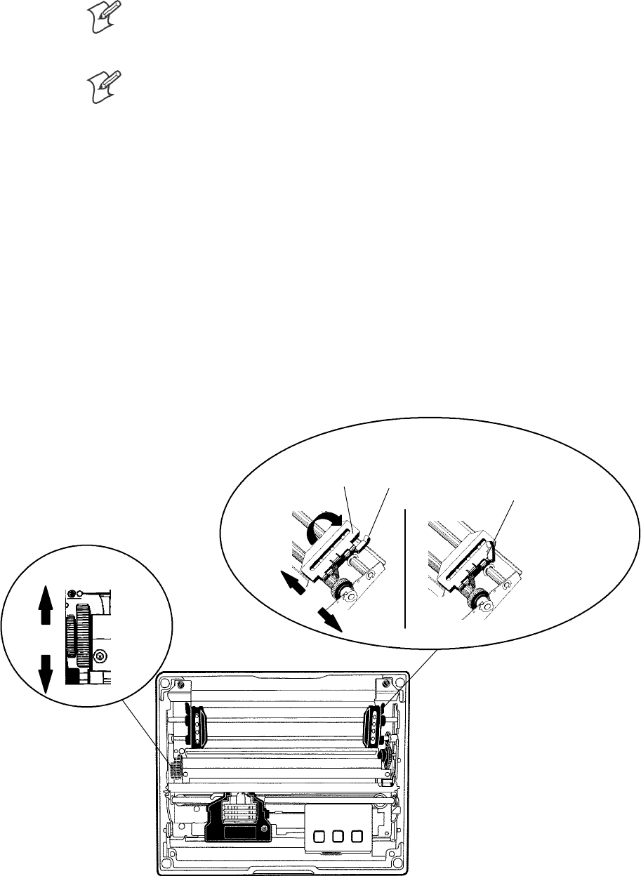
Adjusting the Pinfeed Holders
Note: There are two pinfeed holders, one next to the green thumb wheel
and one opposite the same wheel. Always loosen the pinfeed holder oppo-
site the green thumb wheel.
Note: Adjusting the pinfeed holder next to the green thumb wheel may
cause information to print in the wrong place. If this pinfeed holder is
moved, correct its location by releasing the pinfeed holder tab, moving the
pinfeed holder as close to the green thumb wheel as possible, then locking
the pinfeed holder tab, before adjusting the opposite pinfeed holder.
If the paper does not fit on the two pinfeed holders properly, follow these
steps to adjust the area between the two pinfeed holders to fit the width of
the paper. See the following illustration.
1With the pinfeed holders open, release the locking tab on the pinfeed
holder opposite the green thumb wheel.
2Adjust the pinfeed holder position so that the pins align with the paper.
3Close the pinfeed holder.
4Ensure that the paper is smooth (no folds, bulges, bows, etc.) between
the pinfeed holders. If so, push the locking tab down on the pinfeed
holder that you adjusted.
Locked
pinfeed holder
locking tab
Pinfeed
holder
Released
pinfeed holder
locking tab
Thumb wheel
(green)
OperationChapter —2
22 6820 Series 80-Column Printer User’s Manual
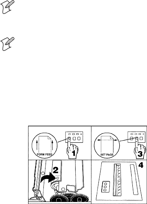
Setting the Paper
Do the following to feed the paper into the printer:
1Press the FORM FEED button on the control panel to feed the paper
into the printer.
2Lower the paper bail. An empty printer autofeeds new paper approxi-
mately 0.1” (0.25 cm) beyond the top of the paper bail.
Note: The ideal distance to feed paper beyond the paper bail may vary
due to environmental conditions (such as humidity) and specific aspects
of certain paper. Use the green thumb wheel to position the paper to a
desired distance per your conditions.
Note: If your paper has a preprinted logo on every page, make sure the
print head is below the preprinted logo. If not, you can adjust the posi-
tion of the paper, either by pressing the LINE FEED button, or by us-
ing the green thumb wheel.
3Once the paper is properly positioned, press the SET PAGE button,
thus clearing the PAPER OUT light, and to indicate where the top of
thepageis.
4Close the printer lid. Ensure that the paper passes through the paper slot
when the printer begins to print.
Operation—Chapter 2
236820 Series 80-Column Printer User’s Manual
Inserting Computer in Terminal Holder
Note: When removing the computer, do not press the computer keys
against the terminal slide retainer. Always store the computer in the termi-
nal holder.
Thefixedmountorportableprintershaveterminalholderoptionsforthe
4000 Series, 61XX, 62XX, 600 Series, 700 Series, or CK60 Computer.
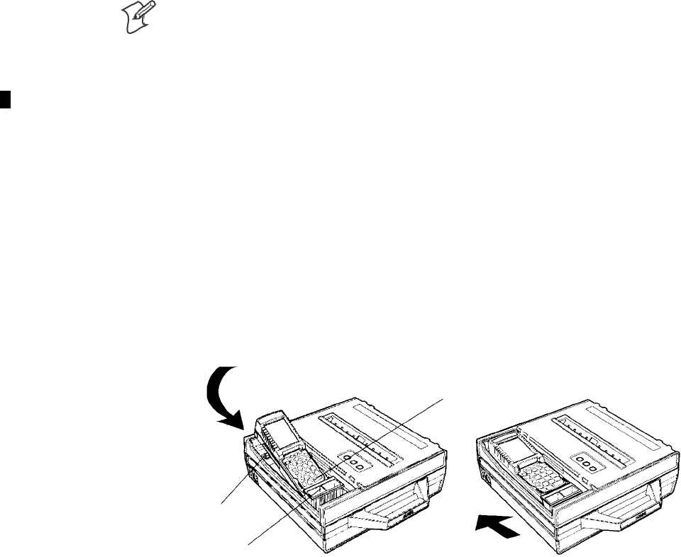
Inserting a 4000 Series or a 62XX Computer
Do the following to insert either a 4000 Series or a 62XX Computer into
the terminal holder:
1Insert the bottom of the computer into the terminal slide retainer.
2Use the computer to push the terminal slide retainer all the way in the
direction shown. See part Ain the following illustration.
3Lower the connector end of the computer into the terminal holder.
4Slide the computer to fully seat it in the printer docking connector. See
part Bin the following illustration.
(A) (B)
Bottom (or battery)
end of computer.
Terminal slide retainer
Computer connector
end in printer
OperationChapter —2
24 6820 Series 80-Column Printer User’s Manual
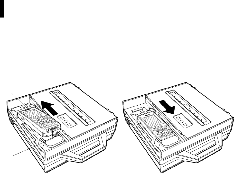
Inserting a 61XX, a 600 Series, a 700 Series, or a CK60 Computer
Do the following to insert a 61XX, 600 Series, 700 Series, or CK60 Com-
puter into the terminal holder:
1Insert the top of the computer into the terminal slide retainer.
2Use the computer to push the terminal slide all the way in the direction
shown. See part Ain the following illustration.
3Lower the connector end of the computer into the terminal holder.
4Slide the computer to fully seat it in the docking connector. See part B
in the following illustration.
(A)
1. Top (display) of computer inserted in terminal slide retainer
2. Docking connectors
1
2
(B)
This illustration shows a 700 Series computer.

256820 Series 80-Column Printer User’s Manual
Maintenance
3
The printer lasts longer and performs better when it is operated correctly
and kept clean.

MaintenanceChapter —3
26 6820 Series 80-Column Printer User’s Manual
Operating Guidelines
Do
Ensure that the computer remains connected to the printer throughout printing or operation.
Make sure the printer cover is closed (except during maintenance or when loading paper).
Ensure there is paper properly installed in the paper tray or dashboard mount.
Disconnect the printer power cable when jump-starting the vehicle.
Clean the external surface of the printer using a soft cloth moistened with mild soap and water, a good quality
cleaner, such as MICRO-CLEAN II, and if necessary, rubbing alcohol.
Make sure your printer is loaded with paper before communicating with your mobile computer.
Do Not
Spill liquids or food crumbs into the printer.
Sit or stand on the printer.
Usesolventsorabrasivecleanersontheprinter.
Rest objects on, under, or against the printer.
Allow the printer to be knocked over or physically damaged.
Start or stop the vehicle engine while printing.
Overload paper tray (paper jams will occur).
Use objects to remove paper from between the print head and platen (damage to mask spring/print head will occur).

Maintenance—Chapter 3
276820 Series 80-Column Printer User’s Manual
General Cleaning
CAUTION: Do not use glass cleaners with ammonia. Permanent
damage to the printer cover will occur if such glass cleaners are used.
CAUTION: Do not use abrasives or solvents (or any product
containing these substances) to clean any part of the unit. Permanent
damage to the printer will occur if such substances are used.
CAUTION: Never use ketonic solvents (acetone or ketone) or
aromatic solvents (toluene or xylene) to clean any part of the printer.
Doing this can damage the printer.
Note: MICRO-CLEAN II is the only cleaner recommended for this pur-
pose. Other cleaners can damage the case.
Note: GUIDE SHAFT CLEANER is recommended for cleaning your
80-column printer guide shafts. Cleaning the printer guide shaft can re-
duce the number of head jams caused by dirt and buildup.
Note: Both cleaners are sold separately. See “Inside Sales”inChapter1for
ordering information and part numbers.
Periodic cleaning helps maintain the appearance and reliability of the
printer. When cleaning the printer, inspect both the outside and the inside
for obvious signs of damage, wear, or impending failure.
Cleaning the Outside
Do not pour liquid cleaners directly on the printer case. Instead, dampen a
soft, lint-free cloth with a quality cleaner and clean the exterior surfaces
with this cloth. Do not use solvent solutions. Inspect the dc power jack, all
cables, and the remote terminal holder or vehicle dock for damage.
MaintenanceChapter —3
28 6820 Series 80-Column Printer User’s Manual
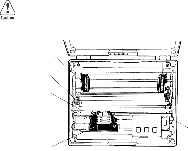
Cleaning the Inside
CAUTION: Let the printer cool before you clean the inside of the
printer, or you may burn your fingers.
Open the printer cover and inspect the ribbon cartridge and all visible
moving parts on the printer mechanism for signs of wear or damage.
Pinfeed holder
Thumb wheel (green)
Paper bail
Ribbon cartridge
Head gap
adjuster
This illustration shows the visible moving parts of the printer mechanism.
Use a low-pressure, dry air source, such as “canned air” available at elec-
tronic supply houses and typewriter repair facilities, or a vacuum, to re-
move accumulated paper dust from the printer mechanism.
The printer ribbon contains a special lubricant to ensure that the fine dot
wires inside the print head receive adequate lubrication. Replace the rib-
bon frequently to prolong the life of the print head. The printer requires
no additional user-applied lubrication. Ribbon cartridges, available in
black or purple, are sold separately. See “Inside Sales” in Chapter 1 for or-
dering information and part numbers.
Maintenance—Chapter 3
296820 Series 80-Column Printer User’s Manual
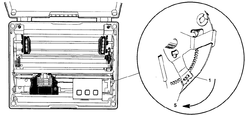
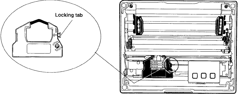
Removing Old Ribbon Cartridge
Physically move the print head mechanism to an open area, then do the
following to remove the old ribbon cartridge:
1Squeeze the ribbon cartridge locking tab (on the side of the cartridge)
against the ribbon cartridge.
2Lift the ribbon cartridge to remove the ribbon from the print head. En-
sure the ribbon does not catch.
3Lift the ribbon cartridge out of the printer.
MaintenanceChapter —3
30 6820 Series 80-Column Printer User’s Manual
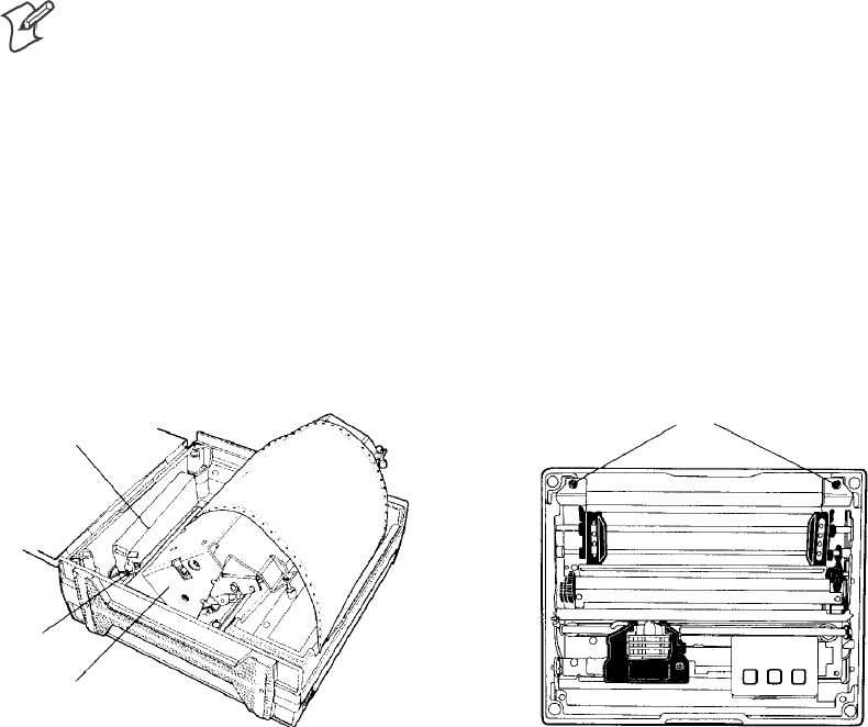
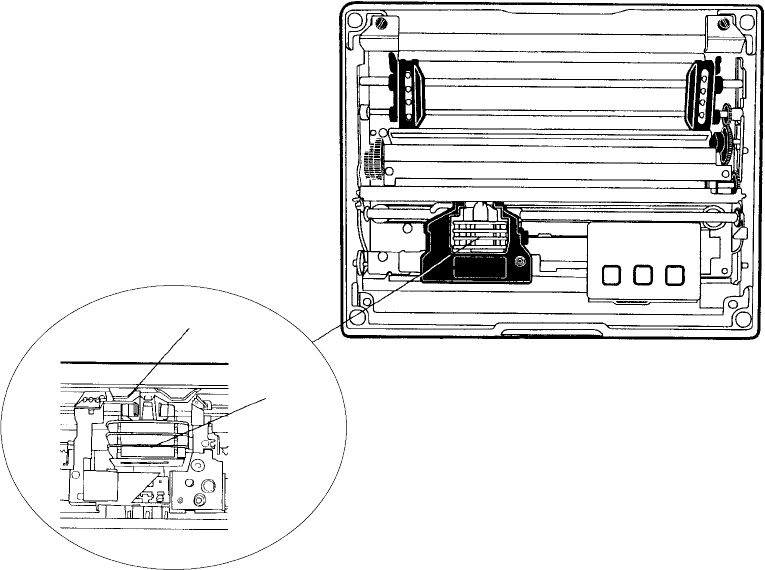
Cleaning the Mask Spring
Look at the mask spring behind the print head. If the mask spring needs to
be cleaned, go on to the next page. If the mask spring appears to be in
good condition, install a new ribbon cartridge as described on page 16.
Print head
Mask spring
This shows the location of the mask spring.
Maintenance—Chapter 3
316820 Series 80-Column Printer User’s Manual
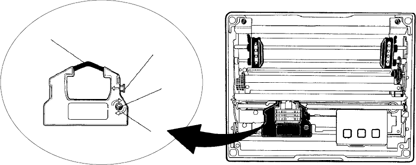
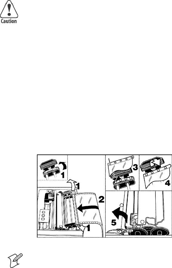
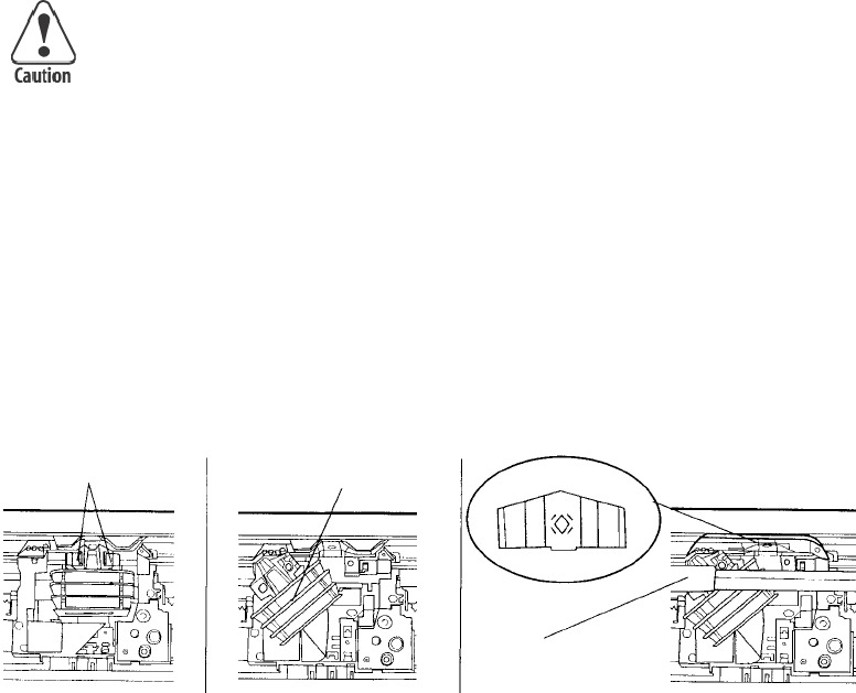
Do the following to clean the mask spring:
1Unlatch the print head locking tabs to release the print head, lift the
print head aside, then lift up the paper bail. Donotdetachtheprinthead
unit.
CAUTION: Never use a sharp object, such as pinchers, to clean
between the print head and the platen (rubber roller). This can
damage the mask spring and print head.
2Remove the clear plastic paper guide that seats the mask spring, if neces-
sary. Use your fingernails to loosen the base of the paper guide, then
pull the paper guide straight up from the printer mechanism.
3Removethemetalmaskspringfromthepaperguideandcleanwitha
quality cleaner. Replace if damaged.
4Put the good, clean mask spring into the paper guide and install the pa-
per guide into the printer.
5Close the paper bail, reinsert the print head, latch the two print head
locking tabs, and install the ribbon.
Print head
locking tabs
Print head
(lifted aside) Mask spring
Paper bail (raised)

MaintenanceChapter —3
32 6820 Series 80-Column Printer User’s Manual
Changing the Printer Settings
Note: If your printer configuration matches either of the following condi-
tions (manufacturing date or control program version #), then you may
not be able to use your printer control panel to reconfigure the printer.
For units built after March 15, 1999 (line 4on your self-test report for the
manufacturing date under the “MFG Date” header) or with control pro-
gram versions greater than 1.67 (line 10 on the self-test report), you do
need to use the configuration utility to change settings. See Chapter 4,
“Using the 6820 Printer Configuration Utility” for information on using the
configuration utility to reflash your printer.
Note: Old printers can be updated with newer control program versions.
The following configuration information applies to units with control pro-
gram versions 1.67 or older.
On rare occasions, you may need to reconfigure the printer. Use the con-
trol panel to enter the following modes and set the printer. Factory defaults
are in bold:
SProtocol Selection
Sets the protocol (NPCP or DTR)
SConfiguration
SAutofeed (CR versus CR+LF)
SBit Rate (9600 bps or 19.2K)
SZero Print Option (slashed (4)or unslashed (0))
Protocol Selection Mode
Press and hold both the FORM FEED and LINE FEED buttons until you
hear a beep to activate the protocol selection mode. See the Protocol
Binary Sequence table on page 33 for available protocols in the order they
are stored. The PAPER OUT, HEAD JAM, and LOW BATT lights turn
ON or OFF in combinations to indicate which protocol is selected for the
printer. (Factory default is NPCP, all three indicators must be OFF.)
Configuration Mode
Press and hold both the SET PAGE and LINE FEED buttons, for about
four seconds until you hear a beep, to activate the configuration mode.
Setting the Autofeed
SIf the LOW BATT indicator stays dark, autofeed is set to CR only
when the printer receives a CR in the input data.
SIf the same indicator is lit, autofeed is set to LF+CR and a linefeed is
performed when a CR is received in the input data stream from the
host.
Press LINE FEED to toggle these two autofeed options.

Maintenance—Chapter 3
336820 Series 80-Column Printer User’s Manual
Selecting the Bit Rate
SIf the PAPER OUT indicator is lit, the printer is set for “19.2K.”
SIf the same indicator stays dark, the printer is set for “9600 bps.”
Press the FORM FEED button to toggle these bit rates.
Adjusting the Zero Print Option
SIf the HEAD JAM indicator is lit, the zero print option is set for the
zero with a slash (4) to appear in printouts.
SIf the HEAD JAM indicator stays dark, the zero print option is set for
the zero without a slash (0) to appear in printouts.
Press the SET PAGE button to toggle between these zero print options.
After selecting configurations, press both SET PAGE and LINE FEED
buttons and listen for a beep to take the printer out of the “Configuration
Mode.” Warm-start the printer to reset it with the new configurations.
Protocol Binary Sequence
Protocol
PAPER OUT
Indicator
HEAD JAM
Indicator
LOW BATT
Indicator
NPCP (factory default) OFF OFF OFF
Reserved OFF OFF ON
Reserved OFF ON OFF
Reserved OFF ON ON
DTR no parity ON OFF OFF
DTR odd parity ON OFF ON
DTR even parity ON ON OFF
IrDA ON ON ON
Repeatedly press the LINE FEED button to increment the light sequence
to the protocol of choice (NPCP to IrDA).
Example
If the printer is set for “NPCP” (OFF, OFF, OFF), press the LINE FEED
button four times to increment the protocol selector to the “DTR no par-
ity” protocol (ON, OFF, OFF).
Repeatedly press the SET PAGE button to decrement the light sequence to
the protocol of choice (IrDA to NPCP).
Example
If set for “DTR no parity” protocol (ON, OFF, OFF), press the SET
PAGE button four times to return to “NPCP” (OFF, OFF, OFF).
After you have selected the protocol, press both the FORM FEED and
LINE FEED buttons and listen for a beep. This takes the printer out of
the Protocol Selection Mode. Warm-start the printer to reset it with the
new protocol.
MaintenanceChapter —3
34 6820 Series 80-Column Printer User’s Manual

356820 Series 80-Column Printer User’s Manual
Using the 6820 Printer
Configuration Utility
4
The Intermec
R
6820 Printer Configuration Utility is run on a host com-
puter to manipulate the configuration of a 6820 Printer flash memory.
This chapter describes how to install and use the configuration utility. Be-
fore using the configuration utility, you must connect your host computer
to your printer, go to page 37 for instructions.

Using the 6820 Printer Configuration Utility
Chapter —
4
36 6820 Series 80-Column Printer User’s Manual
Font Modules
Intermec Technologies provides the following font modules for your 6820
Printer:
SNFT00000.MOD — Default International, 4820 compatible
SNFT00437.MOD — IBM/Microsoft compatible Code Page 437
SNFT00932.MOD — JIS Japanese
SNFT00936.MOD — GB2312 Chinese Simplified
SNFT00949.MOD — KSC5601 Korean
SNFT00950.MOD — Big 5 Traditional Chinese
Note: See Appendix C, “PrinterFontTestJobs,” for sample print jobs.
Note that there are three versions of the default font module
(NFT00000.MOD) — Arabic, Turkish, and International. Any one ver-
sion of this module, but not all three versions, can appear in the 6820
Printer Configuration Utility “FONTS” directory and install on the 6820
Printer. The International version of this font module is automatically
placed in the “FONTS” directory when the Configuration Utility is
installed on the host computer.
All three versions are included on the toolkit CD as follows:
SThe Arabic version is included in the “Default Fonts\Arabic” directory.
SThe Turkish version is in the “Default Fonts\Turkish” directory.
SThe International version is in the “Default Fonts\International” direc-
tory.
Once the Configuration Utility is installed on the host computer, any of
these default font modules can replace the existing default font module
(NFT00000.MOD). Copy the desired default font from the appropriate
toolkit CD default fonts directory to the “FONTS” directory of the Con-
figuration Utility. The Configuration Utility has access to any font mod-
ules in this “FONTS” directory.
For Windows 95 and Windows 98 users:
If the default installation process was followed, the configuration utility
“FONTS” directory is located at “6820PRTR\TOOLKIT\FONTS”
where “6820PRTR” is replaced by the actual directory in which you chose
to extract the files.
For Windows 2000 and Windows XP users:
If you followed the default installation process, the Configuration Utility
“FONTS” directory is located at “Program Files\Intermec\6820 Printer
Configuration Utility\FONTS.”
Note: Do not rename the font files in the “FONTS” directory. If you do
so, the files names will not match the data in these files and the fonts will
not work as expected.
Using the 6820 Printer Configuration Utility
—
Chapter 4
37
6820 Series 80-Column Printer User’s Manual
Connecting to the Printer
Connect your printer to your desktop computer via a serial cable. The seri-
al COM Port connector on either your Fixed Mount Printer or your Por-
table Printer is on your printer mechanism, the same side as the green
thumb wheel.
Reset button
Printer
mechanism
(raised)
COM Port connector
Be sure to locate and disconnect the gray terminal holder ribbon cable
connector from the floor of the printer cavity. The cable is located behind
the printer mechanism on the same side as the green thumb wheel and is
the one that is not attached to the printer mechanism.
Disconnect this terminal holder
ribbon cable from the floor of
the printer cavity Ignore this cable attached
to the printer mechanism.
Intermec Technologies provides a printer configuration utility based on
several operating systems that may be used on your host computer. Below
are the operating systems for which the configuration utility is written. Se-
lect your operating system, then go to that page to begin instructions for
your particular configuration utility.
SIf your host computer has either Windows 95 or Windows 98, go to
page 38 for instructions.
SIf your host computer has Windows 2000 or Windows XP, go to page
53.
Using the 6820 Printer Configuration Utility
Chapter —
4
38 6820 Series 80-Column Printer User’s Manual
Instructions for Windows 95 or Windows 98
These instructions apply to desktop computers running either Windows
95 or Windows 98 operating systems.
Installation
All files necessary to configure the 6820 Printer are located in the toolkit,
including the Configuration Utility application program,
RPGPCONF.EXE, and the initialization file, RPGPCONF.INI. The init-
ialization file is used by the Configuration Utility to specify the location
and names of font and printer control program files.
To set up your host computer to use the Configuration Utility, extract the
toolkit files from the self-extracting archive file, NPTK6820.EXE. First,
create a directory, on your host computer, with an appropriate name for
the Configuration Utility files. The name of this directory is your choice.
You could choose to have the files extracted at the root directory of your
host computer. However, the directory used in the example below is
\6820PRTR. Execute the self-extracting file from the target directory while
specifying the path to NPTK6820.EXE in the command line.
Upon executing NPTK6820.EXE, a “TOOLKIT” subdirectory is created,
as well as other associated subdirectories, as shown in the diagram below.
The Configuration Utility application program and the initialization file
are extracted to the TOOLKIT subdirectory. Other files are extracted to
the other subdirectories created by the archive file.
6820PRTR
TOOLKIT
6820SYS
DOS
FONTS
PCFS
This is the directory where
you executed NPTK6820, to
extract the configuration
utility files.
Configuration File Support
The configuration utility allows the user to generate custom configuration
files. These files have the file name extension of “.PCF”, and they reside in
the directory specified in the initialization file. See DEFAULT.PCF, in the
PCFS directory for an example.
Configuration Utility Operation
A configuration consists of a list of fonts, some parameter settings, and op-
tionally, a printer control program.
When the utility is active, it holds a configuration in memory. This is
called the “working configuration”. Initially, this working configuration
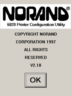
Using the 6820 Printer Configuration Utility
—
Chapter 4
39
6820 Series 80-Column Printer User’s Manual
has no fonts, the parameters are set to the default values, and there is no
printer control program in memory. You should consider the working con-
figuration as temporary and lost when you exit from the utility.
The Configuration Utility’s main menu offers you various ways to manip-
ulate the working configuration. You can overwrite this working confi-
guration with a previously saved configuration, stored either in a disk file
on the computer or in the 6820 Printer itself by using one of the Load
Printer Configuration options. You can modify the working configuration
by using one of the Modify Printer Configuration options. Once the
working configuration is loaded and modified, you can save this to either a
disk file or the printer by using one of the Save Printer Configuration op-
tions.
In addition to the various Load, Modify, and Save options, a Defaults op-
tion is provided, which allows you to restore the printer to a default con-
figuration with a single option.
Starting the Program
When you run RPGPCONF.EXE, the first screen you see is like the fol-
lowing. Click OK to continue to the Main Menu.
Main Menu
The following options are available on the Main Menu.
SUse Load Printer Configuration to load an existing configuration. Load
either from disk or from the printer.
SUse Modify Printer Configuration to review or modify the working
configuration, or include the printer control program in the currently
loaded configuration.
SUse Save Printer Configurations to save a configuration file to disk or
download the working configuration to your 6820 Printer.
SUse Defaults to restore the printer to its default configuration.
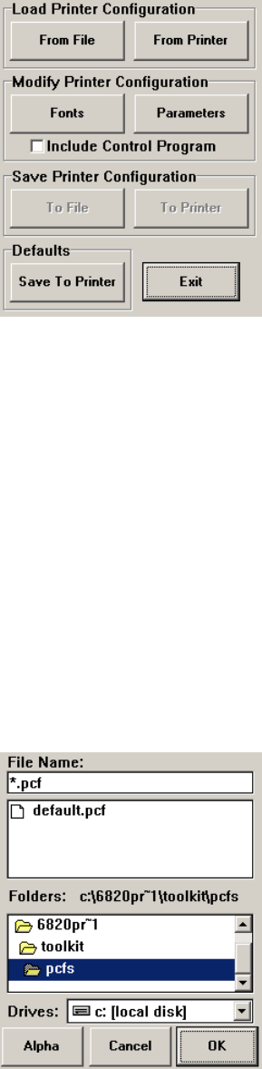
Using the 6820 Printer Configuration Utility
Chapter —
4
40 6820 Series 80-Column Printer User’s Manual
Note that when the Main Menu is first displayed, the Save Printer Con-
figuration options are grayed out, prohibiting selection of those options
until a configuration is loaded or modified.
Exit from the Configuration Utility Program
If you click Exit, a message appears to prompt whether you want to exit.
Click No to return to the Main Menu. Click Yes to exit the program.
Load Printer Configuration
This set of options allows you to load configuration information from disk
(on the host computer) or from the printer (connected to the host com-
puter).
Load Configuration from File option
This option, selected from the Main Menu, allows you to load a configura-
tion file from one of the drives on your host computer.
Click From File from the Main Menu to access the File, Open window.
Here, you can open a configuration parameters file from one of your host
computer drives. It operates like the File, Open on a standard Windows
program.
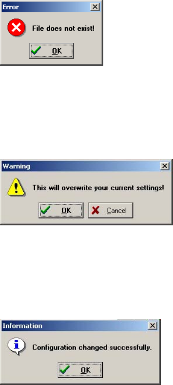
Using the 6820 Printer Configuration Utility
—
Chapter 4
41
6820 Series 80-Column Printer User’s Manual
Canceling the Operation
Click Cancel to return to the Main Menu without selecting a file to open.
Selecting a File Name
You can select the drive, directory, and file name with your pointing de-
vice, using standard MS Windows file selection methods. If you want to
enter text for a file name, you can do this with the alpha keyboard, or use
your host computer keyboard. Click Alpha to access the alpha keyboard
described on page 52.
Loading the Selected File
After selecting a configuration file to load, click OK. If the selected file
does not exist, you see an error message similar to the following. Click OK
to return to the Main Menu without loading a file.
If the file does exist, you see a warning that loading the selected file will
overwrite your working configuration, as shown in the message box below.
Click OK if this is acceptable, otherwise click Cancel to return to the
Main Menu without loading a file.
After clicking OK, the configuration from the selected file is loaded into
memory and becomes the current working configuration. If this load is
successful, a message similar to the one shown below is displayed. Click
OK to return to the Main Menu.
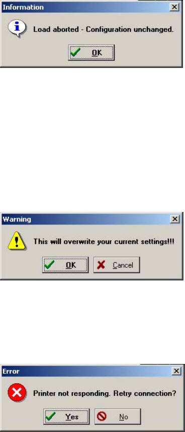
Using the 6820 Printer Configuration Utility
Chapter —
4
42 6820 Series 80-Column Printer User’s Manual
However, if the working configuration is not replaced successfully with the
configuration from the selected file, an error message is displayed inform-
ing you that it was not successful, as shown below. Click OK to return to
the Main Menu without loading a file.
Load Configuration from Printer
This option, selected from the Main Menu, loads a configuration from the
6820 Printer. Click From Printer from the Main Menu to display a warn-
ing message (as shown below) and indicate that the printer’s configuration
will overwrite the working configuration. Click OK to overwrite the con-
figuration, otherwise click Cancel to return to the Main Menu without
loading the printer’s configuration.
If you click OK, a message is then displayed prompting you to reset the
printer. If the connection is not successful, after approximately 20 seconds,
the following message is displayed.
If you click Yes, repeat the previous steps, starting with Attempting a Con-
nection to the Printer.
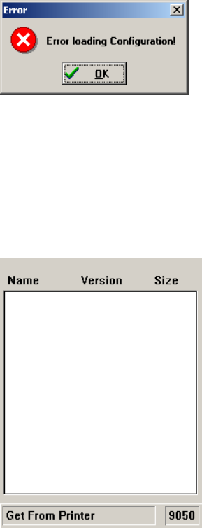
Using the 6820 Printer Configuration Utility
—
Chapter 4
43
6820 Series 80-Column Printer User’s Manual
If you click No, an error message appears (as shown below) is displayed
informing you that the configuration was not loaded. Click OK to return
to the Main Menu without loading the printer’s configuration.
Connection Successful
If the connection to the printer is successful, then no user intervention is
required throughout the remainder of this operation. The Get From Prin-
ter function is initiated, and the Configuration Utility copies the printer
configuration into the working configuration.
This utility communicates with the 6820 Printer to find out the current
parameter settings and which font modules are loaded. The name, version,
and size of these font modules are then displayed on the Get From Printer
screen.
If the operation is successful, you are returned to the Main Menu and the
printer configuration is loaded as the working configuration. You can view
or modify the working configuration by selecting a Modify Printer Con-
figuration option.
Modify Printer Configuration
This set of options allows you to view or change a working configuration,
including adding fonts from disk (on the host computer), deleting printer
fonts, and changing parameters settings.
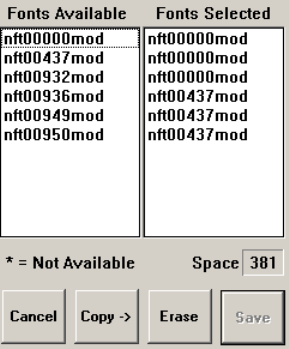
Using the 6820 Printer Configuration Utility
Chapter —
4
44 6820 Series 80-Column Printer User’s Manual
Include Control Program is a switch that determines whether to include
the printer control program when saving the working configuration to the
printer. Click this box to change the setting. When checked, the control
program is included the next time you save the printer configuration.
Generally, you only need to update the control program as new versions
become available. The control program is named NPFL6820.MOD.
Font Selection
This option, selected from the Main Menu, selects fonts that are available
on disk, or deletes existing fonts. A variety of different international fonts
are also available in the toolkit for the 6820 Printer.
Clicking Fonts from the Main Menu takes you to Font Selection where
you can perform operations related to font files,. The Fonts Available list
shows font files that are available on disk. The Fonts Selected list show
fonts that are in the current printer configuration.
Note that Save is grayed out, prohibiting that selection, until either new
fonts are selected, or fonts are removed from the Fonts Selected list.
Copying Font Files
To select font files, highlight the font files in the Fonts Available list, with
your pointing device. You can highlight several files at one time, using
conventional Windows selection methods. Then click Copy to copy those
font files to the Fonts Selected list.
However, if you attempt to copy fonts from the Fonts Available list when
these fonts already exist in the Fonts Selected list, the following error mes-
sage is displayed, once for each of the duplicate fonts (where the current
font file name is listed in place of NFT00000.MOD).
Click OK to close the error message and not copy the font to the Fonts
Selected list. If there are two or more duplicate fonts, the cycle repeats un-
til an error message is displayed for each of the duplicate font files.
The font file names become unhighlighted, you remain in the Font Selec-
tion window, and the duplicate fonts are not copied to the Fonts Selected
list.
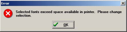
Using the 6820 Printer Configuration Utility
—
Chapter 4
45
6820 Series 80-Column Printer User’s Manual
Deleting Font Files
To avoid the problem of exceeding flash memory, you can delete fonts in
the printer flash, from the Fonts Selected list. To do this, select the font
names you want to delete in the Fonts Selected list, then click Erase to
clear the names from the Fonts Selected list.
Space Remaining in Flash
The Space Selection box, below the Fonts Selected list, displays the space
remaining in flash (in kilobytes), based on fonts currently selected. When
this number is negative, it means the available space in flash is less that the
size of the selected fonts. Delete some fonts before saving the rest.
Saving the Selected Fonts
Note that Save is initially grayed out, disabling its use. Once the Fonts Se-
lected list is changed, Save is enabled (no longer grayed out).
Fontsmarkedwithanasterisk(*),intheFonts Selected list, are currently
in printer flash, but not found on disk, and are lost when flash is updated
from disk (Save to Printer option).
When Save is clicked, and there is enough space in printer flash memory
for the fonts in the Fonts Selected list, the working configuration is up-
dated with the selected fonts. The amount of printer flash memory to
spare, after being loaded with the selected fonts, is shown (in kilobytes) in
the Space box. As long as this number is not negative, there is enough
space for the selected fonts.
However, if you attempt to save fonts and there is not enough space in
printer flash memory, the following error message is displayed. Click OK
to return to the Font Selection window and delete fonts in the Fonts Se-
lected list.
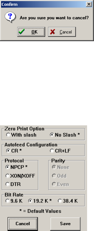
Using the 6820 Printer Configuration Utility
Chapter —
4
46 6820 Series 80-Column Printer User’s Manual
Canceling the Operation
Click Cancel to return to the Main Menu without making any changes. If
you have not made any changes to the Fonts Selected list, you return to
the Main Menu.
However, if you have already made some changes to the Fonts Selected
list, a confirmation message appears, similar to that shown below. Click
OK to return to the Main Menu with changes made to the Fonts Selected
list discarded. Click Cancel to remain in the Font Selection window.
Parameters Selection
This option, selected from the Main Menu, allows you to review or modify
the working configuration.
Click Parameters from the Main Menu to access the Parameters window
where you can modify any of the parameters that are not grayed out. De-
fault parameter values are marked with an asterisk (*).
Modifying Parameters
To modify the configuration, select parameters on this screen using your
pointing device.
Required for Bluetooth — Convert the Printer to Epson DTR Mode
Those using Bluetooth must switch the 6820 Printer from the Norand
Portable Communications Protocol (NPCP) mode to the Epson DTR
mode with the baud rate set to “19.2K” and the parity set to “None.”
Note: The 6820 Bluetooth adapter does not support any other settings.
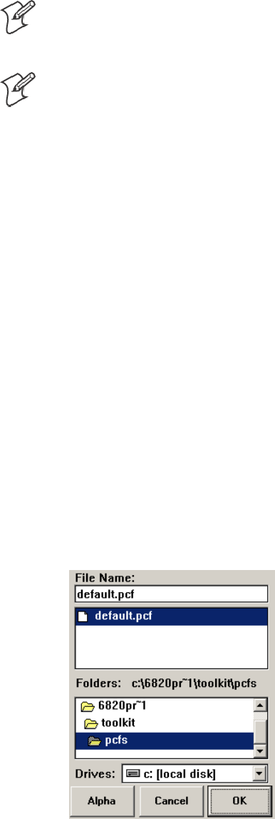
Using the 6820 Printer Configuration Utility
—
Chapter 4
47
6820 Series 80-Column Printer User’s Manual
Note: If your version of the Configuration Utility has a 38.4K bit rate
selection, ignore that selection. If selected, it defaults to 19.2K bps. On
future releases, the 38.8K bit rate will not show on the display.
Note: If your version of the Configuration Utility has an XON/XOFF
selection, ignore that selection. If selected, it defaults to DTR. On future
releases, the XON/XOFF protocol will not show on the display.
Saving Parameters
Clicking Save updates the working configuration and returns you to the
Main Menu.
Canceling the Operation
Click Cancel to return to the Main Menu without modifying any configu-
ration parameters.
Save Printer Configuration
These options allow you to save the working configuration to disk or to
printer.
Save is initially grayed out in the Main Menu,and cannot be used until a
configuration is either loaded or modified.
Save to File
This option, selected from the Main Menu, allows you to select the drive,
directory, and file name with your pointing device, using standard Win-
dows file selection methods.
Click To File from the Main Menu to access the File Save As window
(similar to the File Open window). This option allows you to save the
working configuration to a disk file.
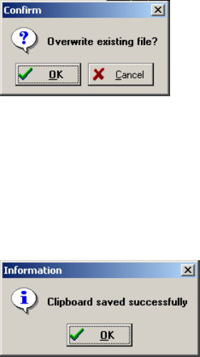
Using the 6820 Printer Configuration Utility
Chapter —
4
48 6820 Series 80-Column Printer User’s Manual
Choosing File Name and Location on Disk
You can select the drive, directory, and file name with your pointing de-
vice, using standard MS Windows file selection methods. If you want to
enter text for a file name, you can do this with the alpha keyboard, or use
your host computer keyboard. Click Alpha to access the alpha keyboard
described on page 52.
Saving the Configuration to Disk
After you have selected the drive, directory, and file name, click OK to
save the configuration file. If a file by the same name exists, the following
confirmation message is displayed, informing you that if you continue it
will overwrite the existing file.
Click Cancel to return to the Main Menu without the working configura-
tion saved to a file.
Click OK for the File Save As operation to continue. The following infor-
mation is displayed assuring you that the working configuration was suc-
cessfully saved to disk. Click OK to return to the Main Menu.
Canceling the “Save to File” Operation
From the File, Save As window, if you click Cancel, this aborts the Save to
File operation, and returns you to the Main Menu without saving the
working configuration.
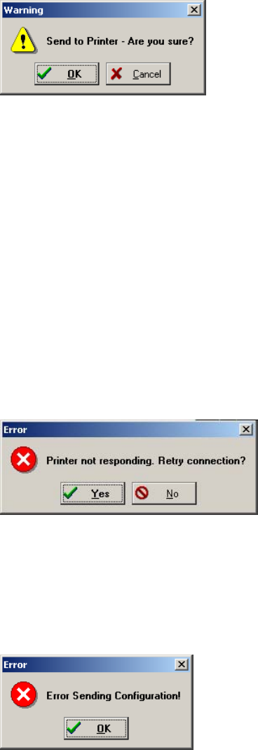
Using the 6820 Printer Configuration Utility
—
Chapter 4
49
6820 Series 80-Column Printer User’s Manual
Save to Printer
This option, selected from the Main Menu, allows you to send the work-
ing configuration to your 6820 Printer.
When To Printer from the Main Menu is clicked, a warning message (as
shown below) is displayed.
This means that the working configuration is copied into flash memory, in
your 6820 Printer, and overwrites the current configuration settings that
are in your printer. Click OK to for the system to connect to the printer
and transfer the configuration, or click Cancel to return to the Main Menu
without updating the printer.
Attempting a Connection to the Printer
After clicking OK, a message is displayed, informing you that the system is
attempting to establish connection with the printer. At this point you
should connect a serial cable (P/N: 226-270-001) between your host com-
puter and the printer (if not already connected), then reset the printer.
Connection Failed
If the connection is not successful after the predetermined period of time
(approximately 20 seconds), the following message is displayed.
Click Yes to repeat the previous steps above (starting with Attempting a
Connection to the Printer), else click No. An error message (as shown be-
low) is displayed informing you that the configuration was not saved.
Click No to return to the Main Menu without updating the printer.
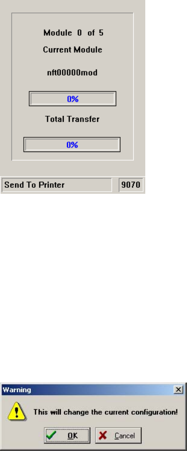
Using the 6820 Printer Configuration Utility
Chapter —
4
50 6820 Series 80-Column Printer User’s Manual
Connection Successful
If the connection is successful, the following screen is displayed, the Send
to Printer function is initiated, and the printer’s configuration is updated
to match the working configuration.
This screen displays the progress made while updating the printer’s config-
uration. Upon completion of this operation, the Total Transfer bar reach-
es 100%, and you return to the Main Menu.
Save Defaults to Printer
Click Save to Printer on the Main Menu to load the default configuration
file, DEFAULT.PCF, and save it to the printer. This combines the opera-
tions of the [from file], the selection of the DEFAULT.PCF file, and the
[to printer] into a single button. The following message appears stating
that the working configuration is overwritten. Click Cancel to return to
the Main Menu without loading the default configuration file.
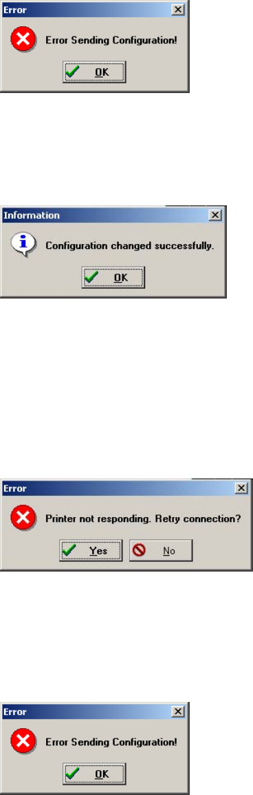
Using the 6820 Printer Configuration Utility
—
Chapter 4
51
6820 Series 80-Column Printer User’s Manual
If you click OK, and if the default configuration file is not successfully
loaded into the working configuration (such as an illegal directory), then
the following error message appears. Click OK to return to the Main
Menu without loading a file.
If the default configuration file is successfully loaded into the working con-
figuration, a message, as shown below, is displayed. Click OK to continue
with the Restore Defaults to Printer operation.
Attempting a Connection to the Printer
If the default configuration was successfully loaded into working configu-
ration, then a message is displayed, prompting you to reset the printer.
Connection Failed
If the connection is not successful, after approximately 20 seconds, the fol-
lowing message is displayed.
Click Yes to repeat the previous steps, above, starting with Attempting a
Connection to the Printer. If you click No, an error message (as shown be-
low) is displayed. Click OK to return to the Main Menu without saving
the default configuration to the printer.
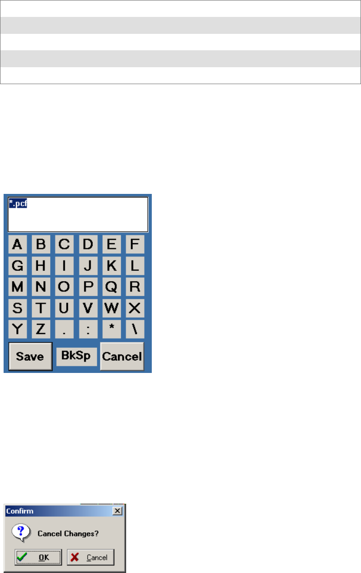
Using the 6820 Printer Configuration Utility
Chapter —
4
52 6820 Series 80-Column Printer User’s Manual
Connection Successful
If the operation was successful, your 6820 Printer is now set to the default
configuration in flash memory, and you are returned to the Main Menu.
Default Printer Settings
These settings are used when Restore Defaults to Printer is selected:
Zero Print Option Slash all zeros (zeros are printed with a slash)
Autofeed Configuration CR (carriage return at end of line without line feed)
Protocol NPCP
Parity N/A (for NPCP)
Bit Rate 19.2K
For other printer defaults, refer to the Printer Defaults paragraph in Appen-
dix B, “Cross-Reference Tables.”
Alpha Keyboard
The Alpha button, on either the File Open window or the File Save As
window, brings up the alpha keyboard onscreen for you to enter text.
Returning the File Name to the Previous Dialog Window
After selecting all of the needed text, click Save to return the text to the
window where needed. Click Cancel to exit without saving the text. The
following confirmation message appears. Click OK to return to the pre-
vious window without the entered text, or click Cancel to stay with the
alpha keyboard.
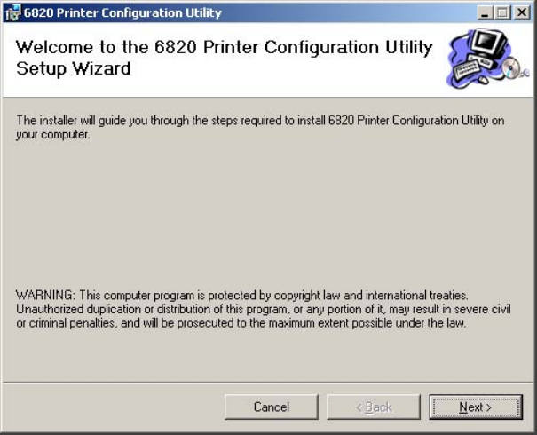
Using the 6820 Printer Configuration Utility
—
Chapter 4
53
6820 Series 80-Column Printer User’s Manual
Instructions for Windows 2000 or Windows XP
These instructions apply to desktop computers running either Windows
2000 or Windows XP operating systems.
Installation
All files necessary to configure the 6820 Printer are located on the CD for
the 6820TKCD toolkit, including the 6820 Printer Configuration Utility
applicationprogram,PCONFIGAPP.EXE.Tosetupyourhostcomputer
to use the Configuration Utility, do the following:
1Insert the toolkit CD in your host computer.
2From your desktop, use your Explorer application to view the contents
of the tookit CD.
3Double-click the SETUP.EXE executable file, then click Next from the
Welcome screen to continue.
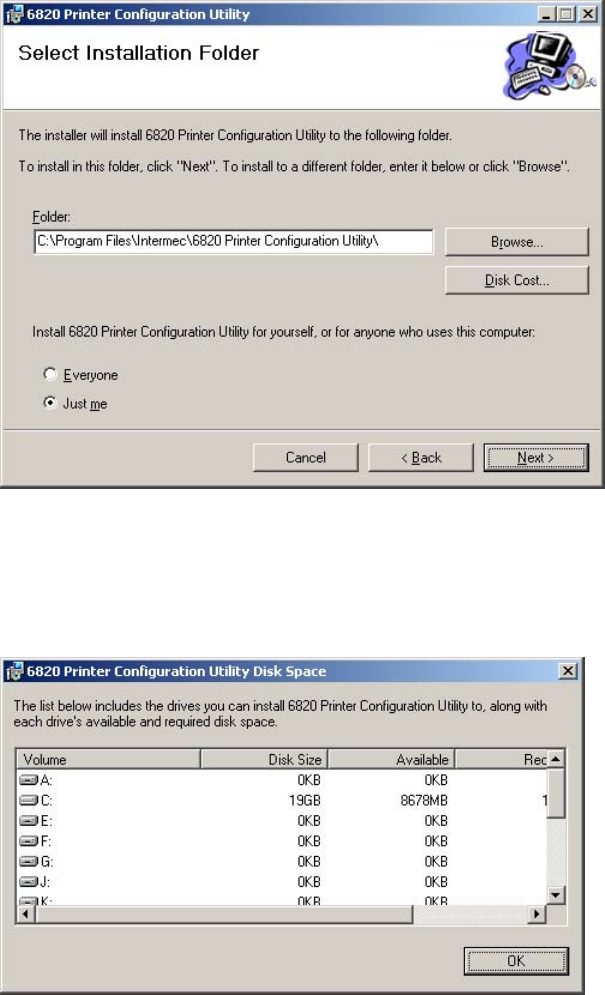
Using the 6820 Printer Configuration Utility
Chapter —
4
54 6820 Series 80-Column Printer User’s Manual
4If you wish to change the default location of this installation, click
Browse to change the destination. If this installation is for anyone who
uses this desktop computer, select Everyone near the bottom of this
screen. Click Next to continue.
If you wish to know the amount of space required for the configuration
utility, click Disk Cost for the following screen. Click OK to close and
return to the installation screens.
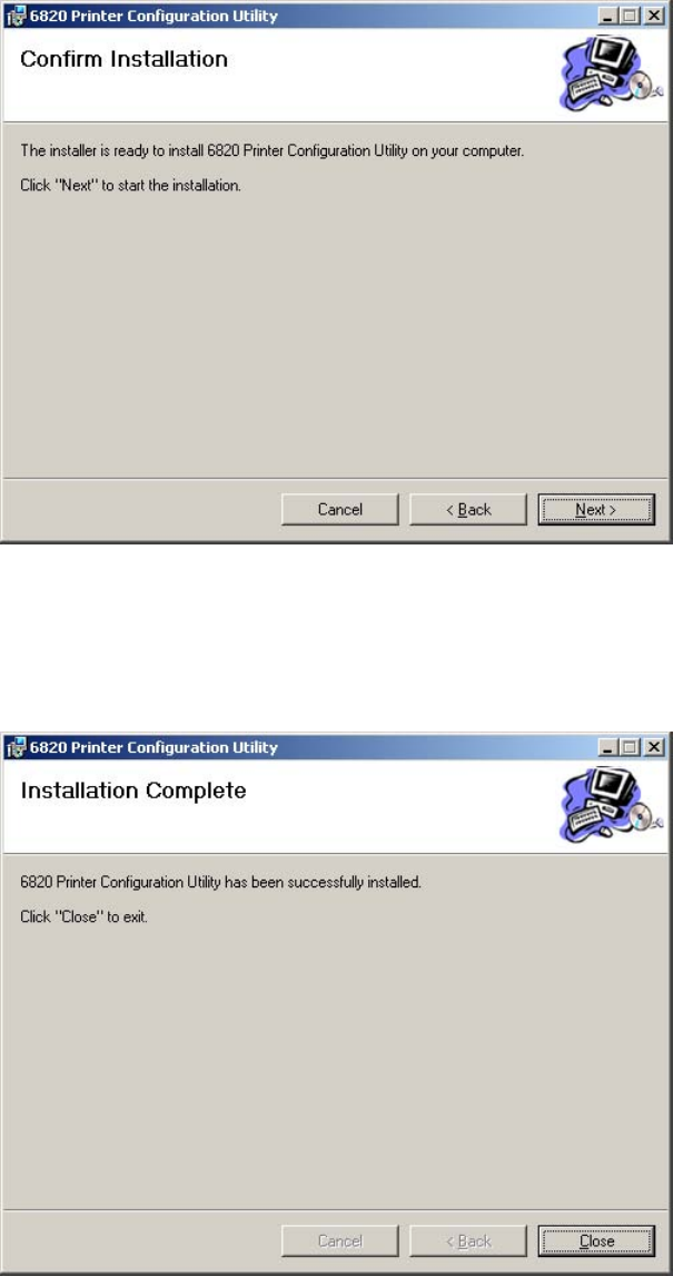
Using the 6820 Printer Configuration Utility
—
Chapter 4
55
6820 Series 80-Column Printer User’s Manual
5Click Next to verify this installation, click Back to adjust the informa-
tion in the previous screen, or click Cancel to exit this installation.
6A progress screen, followed by an Installation Complete screen finishes
this installation. Click Close to exit the installation.
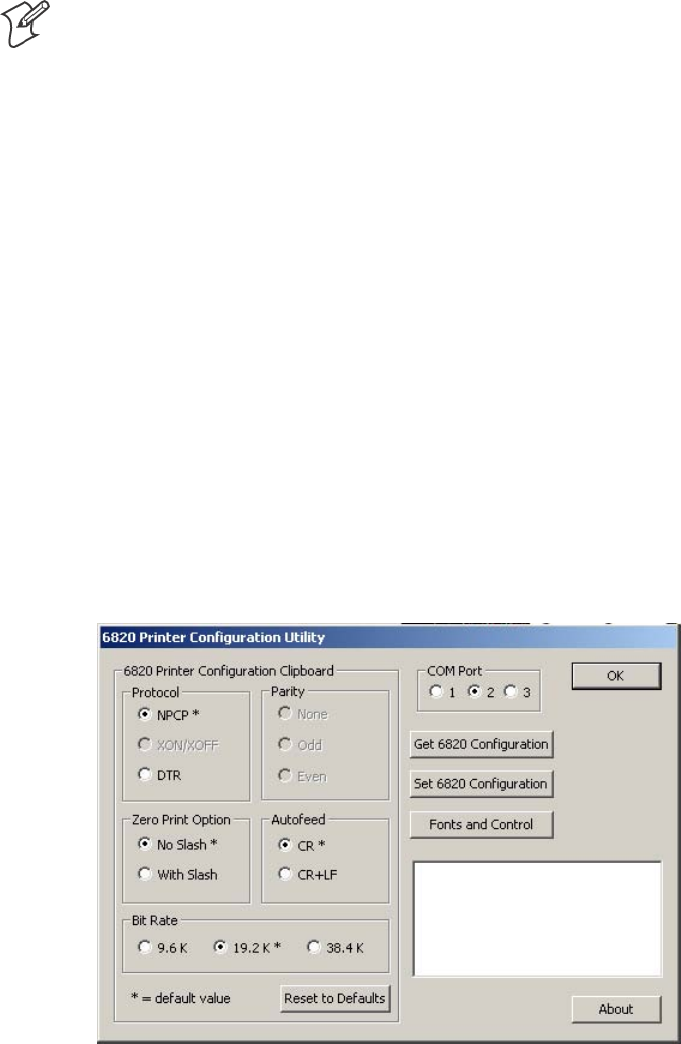
Using the 6820 Printer Configuration Utility
Chapter —
4
56 6820 Series 80-Column Printer User’s Manual
If the default location was not changed in step 4 on the previous page, the
“Program Files\Intermec\6820 Printer Configuration Utility” subdirectory
is created. The Configuration Utility application program and applicable
DLL files are extracted to this subdirectory.
After installation, from your desktop, click Start >Programs >Intermec >
6820 Printer Configuration Utility to access the 6820 Printer Configura-
tion Utility executable and related documentation.
Configuration Utility Operation
Note: If your 6820 Printer has a Bluetooth adapter, its RS-232 line driver
canbeincontentionwiththeconfigurationport’sconnectedprogram-
ming PC. Disconnect the Bluetooth adapter before continuing.
This configuration consists of a list of fonts, some parameter settings, and a
printer control program.
When the utility is active, it holds a configuration in memory. This is
called the “configuration clipboard.” Initially, this configuration has pa-
rameters set to their default values. Consider the contents of the configura-
tion clipboard as temporary and lost when you exit from the utility.
With the Configuration Utility, you can view the configuration stored in
your 6820 Printer using the Get 6820 Configuration button. You can
configure or modify the printer settings in your printer using the Set 6820
Configuration button.
In addition, you can use the Reset to Defaults button to reset the configu-
ration clipboard to the recommended printer configuration. Note that this
button does not send the default configuration to the printer.
Starting the Program
From your desktop, click Start >Programs >Intermec >6820 Printer
Configuration Utility >PConfigApp.exe to access the 6820 Printer Con-
figuration Utility.
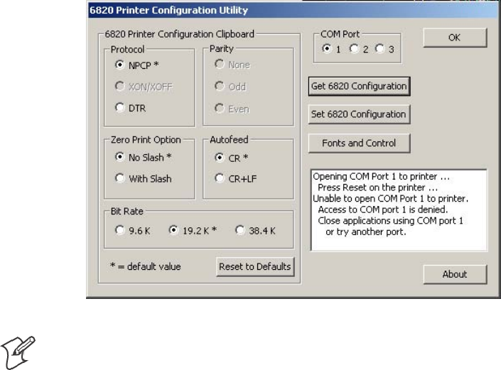
Using the 6820 Printer Configuration Utility
—
Chapter 4
57
6820 Series 80-Column Printer User’s Manual
COM Port
This utility is flexible in which COM Port to use to communicate with
yourprinter.IfCOMPort1isnotavailableorisinusebyanotherap-
plication, select another COM Port with which to connect to your printer.
Establishing a Communication with the Printer
Click either the Get 6820 Configuration or the Set 6820 Configuration
button to open communications with the printer.
1The “Opening COM Port x to printer . . . ” message appears in the text
box of your utility. The “x” in the message indicates to which COM
Port your utility is set.
2When the “Press Reset on the printer” message appears in the text box,
press the reset button on your printer mechanism.
3As soon as successful communication is established between your desk-
top computer and your printer, an “Opening COM Port x to printer. . .
Done.” message appears in the text box.
Note: If an “Unable to open COM Port x to printer” message appears in the
text box, as shown in the previous sample, another software application
may be using the selected COM Port. Either select another COM Port or
disable the software application using the COM Port in question. See page
61 for more errors.

Using the 6820 Printer Configuration Utility
Chapter —
4
58 6820 Series 80-Column Printer User’s Manual
Get 6820 Configuration
To view the settings on your 6820 Printer, do the following:
1Click Get 6820 Configuration to initiate communication.
2The “Getting printer parameters . . . ” message appears in the text box.
3When finished retrieving information from the printer, the “Getting
printerparameters ...Done” message replaces the message described in
step 2. This message indicates parameters were successfully obtained
from the printer and the utility settings reflect your printer settings.
4Either go to “Set 6820 Configuration” in the next paragraph; or click
OK to close the utility, then detach the serial cable.
Set 6820 Configuration
The settings in the configuration clipboard are what is sent into your
printer when you change its configuration.
1In the configuration clipboard, if necessary, select what settings are re-
quiredforyourprinter.To undo your selections and return them to their
defaults, click Reset to Defaults.
2Click Set 6820 Configuration to initiate communication. The “Setting
printer parameters . . .” message appears in the text box of your utility.
3Once settings in your printer are changed, the “Setting printer parameters
...Done” message replaces the message described in step 2.
Note: If the parameters cannot be set, a “Unable to set printer parame-
ters” message is shown. This indicates the connection broke down be-
tween your desktop computer and your printer.
4Click OK to close the utility, then detach the serial cable.
Required for Bluetooth — Convert the Printer to Epson DTR Mode
Those using Bluetooth must switch the 6820 Printer from the Norand
Portable Communications Protocol (NPCP) mode to the Epson DTR
mode with the baud rate set to “19.2K” and the parity set to “None.”
Note: The 6820 Bluetooth adapter does not support any other settings.
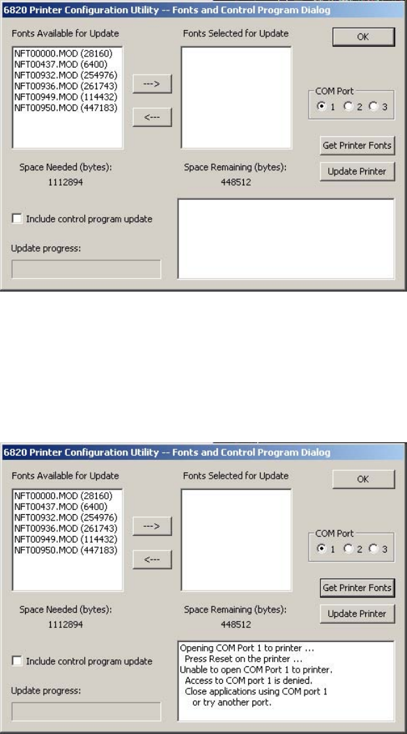
Using the 6820 Printer Configuration Utility
—
Chapter 4
59
6820 Series 80-Column Printer User’s Manual
Fonts and Control
Click Fonts and Control from the 6820 Configuration Utility to update
the fonts stored in your printer or to update the printer control program.
The Fonts Available for Update list shows font files that are available. The
Fonts Selected for Update list show fonts that are to go to the printer.
Get Printer Fonts
To learn what fonts are currently in your printer, click Get Printer Fonts,
then wait for the information to appear in the text box in the bottom right
corner of the dialog. Below is a sample screen.
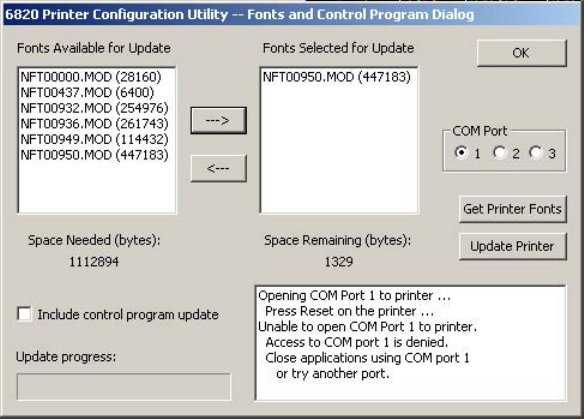
Using the 6820 Printer Configuration Utility
Chapter —
4
60 6820 Series 80-Column Printer User’s Manual
Copying Font Files
To select font files, highlight the font files in the Fonts Available for Up-
date list. You can highlight several files at one time. Then click the right
arrow pointing to the Fonts Selected for Update list to copy the selected
font files to this list. Below is a sample screen.
If you select enough fonts that go over the space allowed, an error message
will appear. Click OK to close the error message and not copy the font to
the Fonts Selected for Update list. If there are two or more fonts that ex-
ceed the space allowed, this message repeats until an error message is dis-
playedforeachofthefontfilesthatwentoverthespaceallowed.
Space in Flash
The Space Needed information shown beneath the Fonts Available for
Update list indicates the total space required (in bytes) for all of the fonts
in the list. The Space Remaining information listed below the Fonts Se-
lected for Update list displays the space remaining in the printer, given the
fonts in the Selected list.
Update Printer
This button updates the printer fonts and the control program depending
on the options selected on the dialog. Note that if the Selected list is empty
and the Include control program update is not checked, a “Nothing selected
for update” message appears in the text box.
SFormats the printer flash for font updates and writes new font files to
the printer for any fonts in the Selected list.
Click the top, right arrow to copy selected font files from the Fonts
Available for Update list to the Fonts Selected for Update list. Click
the bottom, left arrow to remove any selected files from the Fonts Se-
lected for Update list.
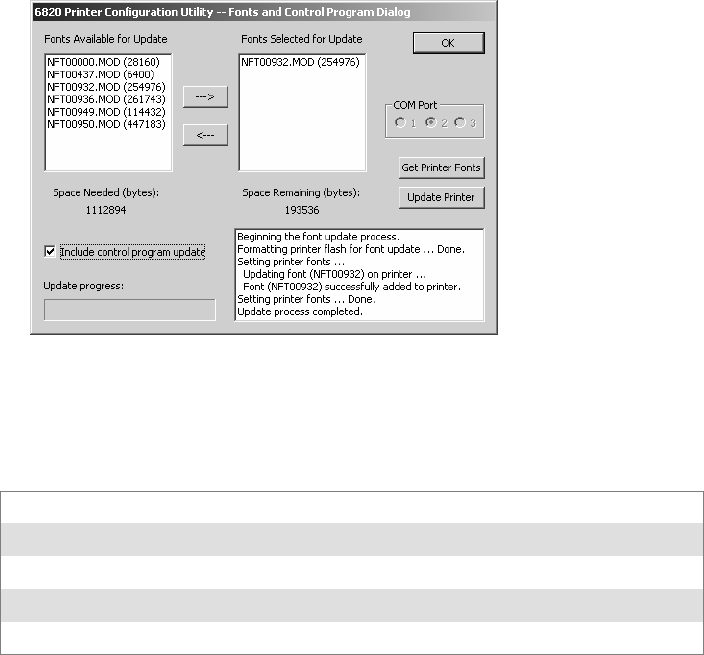
Using the 6820 Printer Configuration Utility
—
Chapter 4
61
6820 Series 80-Column Printer User’s Manual
Click Update Printer to update the fonts in the printer with those in
the Fonts Selected for Update list. The Update progress: bar indicates
the progress as the control program or fonts are written to the printer.
SThe Include program control update box determines whether to in-
clude the printer control program when updating the printer. Check
this box to update the setting and include the control program the next
time you update the printer configuration.
Generally, you only need to update the control program as new versions
become available. The control program is named NPFL6820.MOD.
Default Printer Settings
The following settings are the defaults for your 6820 Printer:
Zero Print Option Print zeros without a slash
Autofeed Configuration CR (carriage return at end of line without line feed)
Protocol NPCP
Parity N/A (for NPCP)
Bit Rate 19.2K (19200)
For other printer defaults, refer to the Printer Defaults paragraph in Appen-
dix B, “Cross-Reference Tables.”
Error Messages
There are three cases where the computer may not connect to the printer.
Here are the three cases and error messages. Note that “x” indicates the
number assigned to the COM Port in question.
Using the 6820 Printer Configuration Utility
Chapter —
4
62 6820 Series 80-Column Printer User’s Manual
Timeout Error
The timeout error may occur due to either of these situations:
SThe printer was not reset in the time allowed.
SThe COM port exists on the desktop computer but nothing is con-
nected to the port.
Error Message:
Unable to open COM port x to printer. Printer not reset
within the time allowed or printer not connected to COM
port x.
Port Not Found Error
The COM port does not exist. The particular COM port is identified in
the error message.
Error Message:
Unable to open COM port x to printer. COM port x cannot
be found.
Access Denied Error
The COM port exists but a connection with the printer is not established.
The particular COM port is identified in the error message.
Error Message:
Unable to open COM port x to printer. Access to COM
port x is denied. Close applications using COM port x
or try another port.
About the Configuration Utility
Click About to learn about your version of the 6820 Configuration Util-
ity. When done, click OK to return to the utility.
Bluetooth Adapter
Note: If your 6820 Printer is to use a Bluetooth adapter, be sure to con-
nect this adapter after you exit the Configuration Utility, thus finish re-
configuring the 6820 Printer fonts.

636820 Series 80-Column Printer User’s Manual
Control Code Definitions
5
This chapter contains a set of control code definitions and specifications
for page layout for the 6820 Printer. These control code definitions are
organized by categories of functions.
To locate control codes easily, several methods have been provided:
SAlphabetically organized (complete list)—
refer to the Control Codes & Escape Sequences Index table in Appendix B,
“Cross-Reference Tables.” Locate the index for the control code, and turn
directly to that page.
SNumeric order (single character codes only)—
refer to the Single Character Control Code Definitions table in Appendix
B, “Cross-Reference Tables.“ Locate the index for the control code, and
turn directly to that page.
SNumeric order (complete list)—
refer to the Escape Sequences Quick Reference table in Appendix B,
“Cross-Reference Tables” and look up control codes by their actual code
values.Locatetheindexfortheescapesequence,andturndirectlyto
that page.

Control Code Definitions
Chapter —
5
64 6820 Series 80-Column Printer User’s Manual
Control Code Definitions
Buffers
I/O Buffer
All characters and control codes received by the printer are stored in this
buffer. Characters and controls codes are read from this buffer and acted
upon to form the print buffer. Characters are removed from the I/O buffer
as they are processed.
Print (image) Buffer
All characters go through this buffer on their way to the printed page. This
buffer contains the graphic image of the dots to print, from which charac-
ters are rendered. It is cleared when its contents are printed.
Special Notations
The following information defines notations included in the format defini-
tions of the escape sequences, throughout this section.
Notation Description
(0) Used in the ASCII column of any of the Format definitions, indicates that its value can only be zero
(and not the character “0”). For example: Select Top-Down Printing ESC US (0).
(1) Used in the ASCII column of any of the Format definitions, indicates that its value can only be one
(and not the character “1”). For example: Select Bottom-Up Printing ESC US (1).
*When a number (at the end of an escape sequence) is marked with an asterisk, then either the value
corresponding to that number or the value of the string character can be used for that number.
For example, if 1* is shown, then either the value (1), or the value of the string character (decimal:
49, hex: 31) can be used.
NUL
T
he NUL character is represented in the Dec column as 0, in the Hex column as 00, and in the
ASCII column as NUL.
General Printer Control Functions
Backspace
The print buffer is emptied. The print head is moved to the left one char-
acter space (using the current pitch). This can be performed to, but not
beyond, the left margin setting. The backspace is ignored if justification of
right, full, or centered is selected.
Format
Decimal Hex ASCII
808 BS
The backspace control code (BS) is not reliable when text contains differ-
ent character pitches. For reliable backspacing, use the escape sequence
(ESC “\”), Set Relative Print Position.

Control Code Definitions
—
Chapter 5
65
6820 Series 80-Column Printer User’s Manual
Beeper
The printer’s sounding device produces a beep sound for approximately
1/10 of a second.
Format
Decimal Hex ASCII
707 BEL
Cancel Line
All of the characters currently in the print buffer are discarded. Current
print position is set to left margin. Text already printed cannot be can-
celed.
Format
Decimal Hex ASCII
24 18 CAN
Carriage Return
The print head is repositioned at the start of the print line (usually at the
left margin), and repositions the pointer to the start of the print buffer,
after printing all data in the buffer. Also, all of the “one line” functions are
reset, such as bold, double-strike, double-wide, or unidirectional printing.
Format
Decimal Hex ASCII
13 0D CR
Note: You can add an automatic line feed with a configuration item (see
Configuration Parameters in Chapter 7, “Troubleshooting and Diagnostics”).
Delete
The last character in the print buffer is deleted. This functions only in left
justification.
Format
Decimal Hex ASCII
127 7F DEL
Form Feed
The contents of the print buffer is printed, the print buffer is cleared, and
the paper is advanced to the top of the next page (Top of Form), according
to the current page length setting. The carriage position is moved to the
start of the line.
Format
Decimal Hex ASCII
12 0C FF

Control Code Definitions
Chapter —
5
66 6820 Series 80-Column Printer User’s Manual
Select Half-Speed Printing
Half-speed mode is turned on to provide quiet printing, and more accurate
print positioning during text mode printing.
Format
Decimal Hex ASCII
27 115 1* 1B 73 01* ESC “s” 1*
Cancel Half-Speed Printing
Half-speed mode is turned off (factory default), and continues with normal
speed printing.
Format
Decimal Hex ASCII
27 115 0* 1B 73 00* ESC “s” 0*
Set Inactivity Time for Sleep Mode
The time period, for which the printer waits during inactivity before it
goes into low-power mode, is set (in nseconds). The factory default is 10
seconds.
Format
Decimal Hex ASCII
27 122 n 1B 7A n ESC “z” n
Line Feed
Perform Line Feed
The contents of the print buffer is printed, then cleared, and the character
count is reset to zero; then the print head advances to the next print line,
using the current spacing. The position of the carriage is not affected and a
carriage return is not executed.
Format
Decimal Hex ASCII
10 0A LF
Perform n/216-inch Line Feed
The paper to immediately advanced n/216 of an inch. This does not affect
subsequent line feeds. Range of nis 0–255.
Format
Decimal Hex ASCII
27 74 n 1B 4A n ESC “J” n

Control Code Definitions
—
Chapter 5
67
6820 Series 80-Column Printer User’s Manual
Perform n/216-inch Reverse Line Feed
An immediate reverse line feed of n/216 of an inch is produced. This does
notaffectsubsequentlinefeeds.Rangeofnis 0–255.
Format
Decimal Hex ASCII
27 106 n 1B 6A n ESC “j” n
Perform Master Reset
The Master Reset code initializes the printer, by resetting all special modes
to their default power-up states (see the Factory Defaults paragraph in Ap-
pendix B, “Cross-Reference Tables” for a complete list of settings that are
initialized with this command).
Format
Decimal Hex ASCII
27 64 1B 40 ESC “@”
Set Print Position (absolute)
The print head is moved to an absolute horizontal position on the paper.
The distance is specified, in dots from the left margin to the new print
position (at which subsequent characters are printed). Each dot represents
1/60 of an inch. The values for n1 and n2 determine the distance, as fol-
lows:
number of dots = n1 + (n2 * 256)
Maximum position is 480. The previous contents of the current print
buffer is printed.
If the position specified would have placed the print head outside the cur-
rent margins, this function is ignored and the previous setting remains ef-
fective. This function is also ignored in right, center, and full justification
modes.
Format
Decimal Hex ASCII
27 36 n1 n2 1B 24 n1 n2 ESC “$” n1 n2

Control Code Definitions
Chapter —
5
68 6820 Series 80-Column Printer User’s Manual
Set Print Position (relative)
The print head is moved to a horizontal position on the paper, relative to
the current print head position. The distance specified is in dots. To deter-
mine n1 and n2, first calculate the displacement required in 1/120ths of an
inch. If the displacement is to the left, subtract it from 65536. The values
for n1 and n2 determine the distance, as follows:
number of dots = n1 + (n2 * 256)
Maximum displacement is ±960. If the position specified would place the
print head outside the current margins, this function is ignored and the
previous setting remains in effect. This function is also ignored in right,
center, and full justification modes.
Format
Decimal Hex ASCII
27 92 n1 n2 1B 5C n1 n2 ESC “\” n1 n2
Select Top-Down Printing
Top-down printing (factory default) is enabled. The first page is printed
first.
Format
Decimal Hex ASCII
27 31 0 1B 1F 00 ESC US (0)
Select Bottom-Up Printing
B
ottom-up printing is enabled. The last page is printed first.
Format
Decimal Hex ASCII
27 31 1 1B 1F 01 ESC US (1)
Select Unidirectional Printing
Unidirectional mode is turned on, causing the print head to print from
left-to-right only. This allows more accurate print positioning during text
mode printing.
Format
Decimal Hex ASCII
27 85 1* 1B 55 01* ESC “U” 1*
Cancel Unidirectional Printing
Unidirectional mode is turned off (factory default), allowing the print head
toprintinbothdirections.
Format
Decimal Hex ASCII
27 85 0* 1B 55 00) ESC “U” 0*

Control Code Definitions
—
Chapter 5
69
6820 Series 80-Column Printer User’s Manual
Select Unidirectional (one line) Printing
Unidirectional printing is turned on, for the current line only. The con-
tents of the print buffer is printed, and cleared, before setting this mode.
This allows more accurate print positioning during text mode printing, for
the current line.
Format
Decimal Hex ASCII
27 60 1B 3C ESC “<”
Page Formatting Functions
This set of functions consists of control codes that change the formatting
for the page, such as page length, margins, line spacing, etc. The page
length (form length) and margin settings define the printable area on the
page. These settings need to conform to the actual size of the paper used in
the printer.
Page Length
Set Page Length (lines)
The length of the paper is set, in lines, where the range of n(number of
lines) is 1-127 (default = 66). Keep in mind the line spacing and actual
length of the paper when specifying this value, since this function is depen-
dent on those parameters. Top-of-Form is reset to the current line and the
Skip Over Perforation setting is canceled.
Format
Decimal Hex ASCII
27 67 n 1B 43 n ESC “C” n
Set Page Length (inches)
The length of the paper is set, in inches, where the range of n(number of
inches) is 1-22 (default = 11). Keep in mind the line spacing and actual
length of the paper when specifying this value, since this function is depen-
dent on those parameters. Also, Top-of-Form is reset to the current line
and the Skip Over Perforation setting is canceled.
Format
Decimal Hex ASCII
27670n 1B 43 00 n ESC “C” NUL n

Control Code Definitions
Chapter —
5
70 6820 Series 80-Column Printer User’s Manual
Line Spacing
These functions set the amount of space from one line to the next, for line
feeds. The factory default is 1/6 inch (6 lines per inch).
The Page Length, Vertical Tab, and Skip Over Perforation functions are
also dependent upon this function.
Select 1/8-inch Line Spacing
Line spacing is set to 1/8 of an inch (8 lines per inch), for subsequent lines.
Format
Decimal Hex ASCII
27 48 1B 30 ESC “0”
Select 7/72-inch Line Spacing (7 dots)
Line spacing is set to 7/72 of an inch (approximately 9.7 lines per inch),
forsubsequentlines.
Format
Decimal Hex ASCII
27 49 1B 31 ESC “1”
Select 1/6-inch Line Spacing
Line spacing is set to 1/6 of an inch (6 lines per inch), for subsequent lines
(factory default). 1/6 inch is equal to 12 dot spacing.
Format
Decimal Hex ASCII
27 50 1B 32 ESC “2”
Select n/216-inch Line Spacing
Line spacing is set to n/216 of an inch, for subsequent lines. A spacing of
1/216 inch is 1/3 the distance between pins of the print head (approxi-
mately 1/3 of a dot) and 27/216 is 8 lines per inch. Range of nis 0–255.
Format
Decimal Hex ASCII
27 51 n 1B 33 n ESC “33” n
Select n/72-inch Line Spacing (n dots)
Line spacing is set to n/72 of an inch, for subsequent lines. A spacing of
1/72 inch (1 point in font size) is the distance between pins on the print
head (approximately 1 dot) and 9/72 is 8 lines per inch. Range of nis
0–85.
Format
Decimal Hex ASCII
27 59 n 1B 41 n ESC “A” n

Control Code Definitions
—
Chapter 5
71
6820 Series 80-Column Printer User’s Manual
Set Margins
Margin settings define the horizontal print area on the page. The mini-
mum space between margins is the width of one double-wide pica charac-
ter.
Set Right Margin
Alltextintheprintbufferiscleared,thentherightmarginissettoncol-
umns, using the current character pitch. This is the number of the charac-
ters from column 1 (at the left edge of the paper) to the last column before
the right margin (factory default = 80).
The minimum space between margins is the width of one double-width
pica character. The maximum value for this setting is the maximum num-
ber of characters (based on the current pitch) that would fit between the
left margin and the right edge of the default printable area of the page.
Ranges shown below could vary, depending on values of other parameters
that affect character width. If the value specified is not within the allowed
range, it is ignored.
Range of nis 2–80 in Pica mode, 2–96 in Elite mode, and 2–136 in Com-
pressed mode.
Format
Decimal Hex ASCII
27 81 n 1B 51 n ESC “Q” n
SetLeftMargin
All text in the print buffer is cleared, then the left margin is set, relative to
the number of columns to the left of the first column to be printed (facto-
ry default = 0).
The minimum space between margins is the width of one double-width
pica character. The maximum value must be less than the right margin.
Ranges shown below could vary, depending on values of other parameters
that affect character width. If the value specified for this function is not
within the allowed range, it is ignored.
Range of nis 0–78 in Pica mode; 0–93 in Elite mode, and 0–133 in Com-
pressed mode.
Format
Decimal Hex ASCII
27 108 n 1B 6C n ESC “I” n

Control Code Definitions
Chapter —
5
72 6820 Series 80-Column Printer User’s Manual
Set Skip Over Perforation
This function is valid for continuous paper only. The number of lines to
skip between the last printed line on the page and the first printed line on
thenextpageisset.Ifthevaluespecifiedforthisfunctionisgreaterthan
the page length, it is ignored. This function is canceled by the use of one of
the Set Page Length functions (factory default = disabled).
The amount of space left blank at the bottom of the printed page is depen-
dent upon the current Line Spacing.
Format
Decimal Hex ASCII
27 78 n 1B 4E n ESC “N” n
Cancel Skip Over Perforation
The Skip Over Perforation is canceled, which allows the maximum number
of lines to be printed on each page.
Format
Decimal Hex ASCII
27 79 1B 4F ESC “O”
Character Style and Text Mode Functions
The following set of functions affect the appearance of text on the printed
page. This could involve size, typeface, or other characteristics of the text.
Select Condensed Mode (compressed)
The condensed mode is selected, which prints characters at approximately
60% of the normal width. This results in character pitches, as shown be-
low (for exact pitch values, see Master Select, on page 75):
Condensed Mode Condensed + Expanded Condensed + Elite
17 cpi (approximate) 9 cpi (approximate) 20 cpi (approximate)
This function empties the print buffer and turns compressed mode on, and
stays on until canceled by Cancel Compressed Mode, ESC SI (0) or DC2
(factory default = disabled). Note that this function is not supported in Dou-
ble-byte Character Sets (DBCS).
Format
Decimal Hex ASCII
27 15 1B 0F ESC SI
15 0F SI

Control Code Definitions
—
Chapter 5
73
6820 Series 80-Column Printer User’s Manual
Cancel Condensed Mode (compressed)
This function cancels the compressed mode, enabled by Select Compressed
Mode, SI or ESC SI (1). Note that this function is not supported in DBCS.
Format
Decimal Hex ASCII
27 18 1B 12 ESC DC2
18 12 DC2
Select Double-Strike Mode
Double-strike printing is enabled, until Cancel Double-Strike Mode is en-
countered. Factory default disables double-strike. Text is made bolder by
printing each dot twice, with the second dot slightly below the first dot.
This mode is not available in NLQ, yet is not canceled by the selection of
NLQ. Note that this function is not supported in DBCS.
Format
Decimal Hex ASCII
27 71 1B 47 ESC “G”
Cancel Double-Strike Mode
The effect of Select Double-Strike Mode is canceled. Note that this function
is not supported in DBCS.
Format
Decimal Hex ASCII
27 72 1B 48 ESC “H”
Select Double-Wide (expanded) Mode (one-line-only)
Expanded print is enabled, for current line only. The mode set previously
returns on subsequent lines. However, expanded print can be canceled
with Cancel Expanded Print, DC4 or ESC “W” (0), before end of current
line, or wrapping of the print buffer. This works with all three pitches
(Pica, Elite, Compressed).
This mode is also terminated by the execution of a Carriage Return,Line
Feed,Form Feed,Vertical Tab or wrapping of the print buffer. Note that
this function is not supported in DBCS.
Format
Decimal Hex ASCII
27 14 1B 0E ESC SO
14 0E SO

Control Code Definitions
Chapter —
5
74 6820 Series 80-Column Printer User’s Manual
Cancel Double-Wide (expanded) Print (one-line-only)
Double-Wide (expanded) print mode is canceled for the current line only.
Modes set previously return on subsequent lines. However, it does not
cancel expanded mode set by Select Double-Wide (expanded) Mode,ESC
“W” (1) or Master Select, ESC “!”.Note that this function is not supported in
DBCS.
Format
Decimal Hex ASCII
27 20 1B 14 ESC DC4
20 14 DC4
Select Double-Wide (expanded) Mode
Expanded print mode is enabled, until Cancel Expanded Print is encoun-
tered. Factory default disables double-wide mode. Note that this function is
not supported in DBCS.
Format
Decimal Hex ASCII
27 87 1* 1B 57 01* ESC “W” 1*
Cancel Double-Wide (expanded) Mode
Double-wide print mode (previously set by Select Double-Wide Mode)is
canceled. Note that this function is not supported in DBCS.
Format
Decimal Hex ASCII
27 87 0* 1B 57 00* ESC “W” 0
Select Elite Pitch
A character pitch of 12 cpi (characters per inch) is selected. This also can-
cels Pica Pitch (factory default = Pica). Note that this function is not sup-
ported in DBCS.
Format
Decimal Hex ASCII
27 77 1B 4D ESC “M”
Select Emphasized Mode
Emphasized printing is enabled, until Cancel Emphasized Mode is encoun-
tered. The text is made bolder by printing each dot twice, with the second
dot slightly to the right of the first dot. Factory default disables Empha-
sized mode. Note that this function is not supported in DBCS.
Format
Decimal Hex ASCII
27 69 1B 4B ESC “E”

Control Code Definitions
—
Chapter 5
75
6820 Series 80-Column Printer User’s Manual
Cancel Emphasized Mode
The effect of the Select Emphasized Mode is canceled. Note that this function
is not supported in DBCS.
Format
Decimal Hex ASCII
27 70 1B 46 ESC “F”
Define Intercharacter Space
This function defines the amount of space to the right of each character, in
addition to the space allowed in the character design. The variable nrepre-
sents the number of units of space, with each unit equal to 1/120 of an
inch. Range of values for nis 0–63 with a factory default of 0.
Format
Decimal Hex ASCII
27 32 n 1B 20 n ESC SP n
Select Italic Mode
The text (nongraphic) characters are italicized. Factory default disables
Italic mode. Note that this function does not work well with DBCS or alter-
nate Single Byte Charater Sets (SBCS).
Format
Decimal Hex ASCII
27 52 1B 34 ESC “4”
Cancel Italic Mode
The italic mode, set by the Select Italic Mode function, is canceled. Note
that this function does not work well with DBCS or alternate SBCS.
Format
Decimal Hex ASCII
27 53 1B 35 ESC “5”
Master Select
Combinations of modes are allowed with this function. The variable nis
determined by combining values for the desired modes, by adding them
together. Note that this function is not supported in DBCS.
Format
Decimal Hex ASCII
27 33 n 1B 21 n ESC “!” n

Control Code Definitions
Chapter —
5
76 6820 Series 80-Column Printer User’s Manual
Valid combinations of the values in the following table include any com-
binations except that Pica cannot combine with Elite.
An example of combining values: Pica Compressed Italic Underlined, by
adding values (00h + 04h + 40h + 80h), which results in C4h for the val-
ue of n.
Hex Value Mode
00h Pica
01h Elite
04h Condensed (compressed)
08h Emphasized
10h Double-Strike
20h Double-Width (expanded)
40h Italic
80h Underlined
The following print conflicts occur between modes. A mode in any col-
umn takes precedence over all modes in the columns to its right.
1 2 3
Elite Emphasized Compressed
The following print modes can be combined producing different pitches:
Pitch Mode
5cpi Expanded
6cpi Expanded Elite
8.58 cpi Expanded Compressed
10 cpi Pica
12 cpi Elite
17.16 cpi Compressed
Select Pica Pitch
A character pitch of 10 cpi (characters per inch) is selected (factory de-
fault). This also cancels Elite pitch. Note that this function is not supported
in DBCS.
Format
Decimal Hex ASCII
27 60 1B 50 ESC “P”

Control Code Definitions
—
Chapter 5
77
6820 Series 80-Column Printer User’s Manual
Select Superscript Mode
All subsequent characters are printed approximately 2/3 the normal height
in the upper part of the character space, until Cancel Subscript/Superscript is
encountered. Note that this function is not supported in DBCS.
Format
Decimal Hex ASCII
27 83 0* 1B 53 00* ESC “S” 0*
Select Subscript Mode
All subsequent characters are printed approximately 2/3 the normal height
in the lower part of the character space, until Cancel Subscript/Superscript is
encountered. Note that this function is not supported in DBCS.
Format
Decimal Hex ASCII
27 83 1* 1B 53 01* ESC “S” 1*
Cancel Subscript/Superscript Mode
The effects produced by Select Superscript Mode and Select Subscript Mode
are canceled. Factory default also disables both of these modes. Note that
this function is not supported in DBCS.
Format
Decimal Hex ASCII
27 84 1B 54 ESC “I”
Select Underline Mode
The underlining of all subsequent characters (including spaces) is enabled,
until the Cancel Underline Mode function is encountered.
Format
Decimal Hex ASCII
27 45 1* 1B 2D 01* ESC “–” 1*
Cancel Underline Mode
The effect of the Select Underline Mode function is canceled. Factory de-
fault also disables the Underline mode.
Format
Decimal Hex ASCII
27 45 0* 1B 2D 00* ESC “–” 0*

Control Code Definitions
Chapter —
5
78 6820 Series 80-Column Printer User’s Manual
Tabs and Tab Setting Functions
Horizontal Tabs
This set of functions deals with horizontal tabs: set tabs, tab to next tab
stop,cleartabs,andsettabincrements.
STab settings are not affected by subsequent changes in pitch.
STabs may range up to maximum width for character and printer size.
SAll previous tab stops are cleared when new tab stops are set. Also, if the
left margin is changed after the horizontal tabs are set, then all tab stops
are cleared.
STabs become absolute positions and are not affected by any subsequent
change in character size.
SAll tabs set outside of the printable area are ignored.
Perform Horizontal Tab
The print position is moved to the next horizontal tab stop. The tab posi-
tions, set by ESC “D”, the Set Horizontal Tabs function, are not affected
by any changes in character pitch.
The factory default tab settings are at intervals of eight characters, in the
currently selected pitch. For the default tabs, the actual distance to each
tab position is affected by changes in character pitch.
Format
Decimal Hex ASCII
909 HT
Set Horizontal Tabs
The current horizontal tabs are reset, and new horizontal tabs are set up,
based on the current character width (pitch).
Format
Decimal Hex ASCII
27 68 n1 n2 ... nk 0 1B 44 n1 n2 ... nk 00 ESC “D” n1 n2 ... nk NUL
where, n1 is the first tab (range of values for tab stops: 1–255), n2 is the
second tab (all tabs must be in ascending order),... are subsequent tabs
(maximum number of tabs: 32), nk is the last tab to set (any value less
than the previous tab value acts as a terminating character), NUL is the
terminating character.
Clear Horizontal Tabs
All horizontal tab stops are cleared. It is merely a variant behavior of the
Set Horizontal Tabs function, where the NUL acts as an early terminating
character, since the function normally clears the existing tabs before setting
any new tabs.
Format
Decimal Hex ASCII
27 68 0 1B 44 00 ESC “D” NUL

Control Code Definitions
—
Chapter 5
79
6820 Series 80-Column Printer User’s Manual
Vertical Tabs
This set of functions deals with vertical tabs: set tabs, tab to next tab stop,
clear tabs, set tab increments, set tabs in channels, and select a tab channel.
STab positions are line numbers, counting from the Top of Form.
SAll tabs set beyond the page length are stored, but are not used.
SAny tab set within the SOP range (Skip Over Perforation), during the
time SOP is active, are stored but not used until SOP is canceled.
SIf a vertical tab is encountered, and the next tab stop is outside the
printable page area, a form feed is executed placing the print head at the
next Top of Form.
SAll previous tab stops are cleared when new tab stops are set.
STab settings are not affected by subsequent changes in line spacing.
Perform Vertical Tab
The contents of the current print buffer are printed first, then the print
position is moved to the next vertical tab stop. If no channel is selected,
then channel 0 is used. The carriage position is changed to the start of the
next print line. If the vertical tab is performed beyond the last tab position
set or beyond the last line of a form, then a form feed is performed
.
If no
vertical tabs are defined, then the paper advances one line, using the cur-
rently selected line spacing, without changing the carriage position.
Format
Decimal Hex ASCII
11 0B VT
SetVerticalTabs
The current tabs are reset, and vertical tabs are set up, based on the current
line spacing. Tab settings are not affected by subsequent changes in line
spacing.
Format
Decimal Hex ASCII
27 66 n1 n2 ... nk 0 1B 42 n1 n2 ... nk 00 ESC “B” n1 n2 ... nk NUL
where n1 is the first tab (range of values for tab stops: 1–255), n2 is the
second tab (all tabs must be in ascending order), ... are subsequent tabs
(maximum number of tabs: 16), nk is the last tab to set (any value less
than the previous tab value acts as a terminating character), NUL is the
terminating character. All tab settings with this function are stored in
channel 0.

Control Code Definitions
Chapter —
5
80 6820 Series 80-Column Printer User’s Manual
Clear Vertical Tabs
All vertical tab stops are cleared. It is merely a variant behavior of the Set
Vertical Tabs function, where the NUL acts as an early terminating charac-
ter, since the function normally clears the existing tabs before setting any
new tabs.
Format
Decimal Hex ASCII
27 66 0 1B 42 00 ESC “B” NUL
Set Vertical Tabs in Channel
This function works the same as the Set Vertical Tabs function, except that
it stores the tabs into a specified channel, as specified by the variable c.
This channel is selected for use by the Select Vertical Tab Channel function.
Format
Decimal Hex ASCII
2798cn1n2...nk0 1B 62 c n1 n2 ... nk 00 ESC “b” c n1 n2 ... nk NUL
where cis the channel number (range: 0–7), n1 is the first tab (range of
values for tab stops: 1–255), n2 is the second tab (all tabs must be in
ascending order), ... are subsequent tabs (maximum number of tabs:
16), nk is the last tab to set (any value less than the previous tab value
acts as a terminating character), and NUL is the terminating character.
Clear Vertical Tabs in Channel
All vertical tab stops in the specified channel are cleared. This is merely a
variant behavior of the Set Vertical Tabs in Channel function, where the
NUL acts as an early terminating character, since this function normally
clears the existing tabs before setting any new tabs.
Format
Decimal Hex ASCII
27 98 c 0 1B 62 c 00 ESC “b” c NUL
Select Vertical Tab Channel
A specified tab channel is selected. It sets up the current tabs from that
channel. Once this function is performed, all subsequent Perform Vertical
Tab commands use the tab stops from the list retrieved from the specified
channel. At power on, the printer uses the tabs stored in channel 0.
Format
Decimal Hex ASCII
27 47 c 1B 2F c ESC “/” c
where cis the channel number (range: 0–7)
Control Code Definitions
—
Chapter 5
81
6820 Series 80-Column Printer User’s Manual
Character Sets and User-Defined Functions
Different character sets may be installed in the 6820 Printer. In some cases
more than one character set may be present at one time, depending on the
amount of available font memory. The 6820 Printer reserves 438K of
memory for installable fonts in FLASH memory. You can install these
character sets using NPCP or the flash configuration utility available in the
6820 Tool Kit. They can also install in flash at the time of manufacture or
service. A printer tool kit is available for installing selected font modules.
Single Byte Character Sets
SBCSs are supported for MS-DOS, PL/N, and Intermec application com-
patibility. NFT00000.MOD is the default character set (font) for compati-
bility with the 4820 Printer. NFT00437.MOD is the IBM/Microsoft
compatible character set for codepage 437.
Double-Byte Character Sets
DBCSs require two bytes to send to the printer to define the character to
print. The first byte of the character code sent to the printer is known as a
lead-in byte. The second byte of the character code is known as the trailing
byte. Different character sets have different requirements for the values of
both lead-in and trailing byte. When the lead-in byte does not fall in the
range listed for the character set, a character from a SBCS may print. The
following double-byte character sets are supported by the 6820 Printer.
DBCS
Font Module
Code
Page DBCS Language Lead-in Byte Trailing Byte
NFT00936.MOD 936 GB 2312 Chinese
(simplified)
A1h–ABh
B0h–F7h
A1h–FEh
NFT00950.MOD 950 big 5 Traditional
Chinese
A1h–C6h
C9h–F9h
40h–FEh (except
7Fh)
NFT00932.MOD 932 Shift JIS Japanese 81h–9Fh
E0h–FCh
40h–FCh (except
7Fh)
NFT00949.MOD 949 KSC 5601 Korean A1h–ACh
B0h–C8h
CAh–FDh
A1h–FEh
Note: See Appendix C, “PrinterFontTestJobs,” for sample print jobs.

Control Code Definitions
Chapter —
5
82 6820 Series 80-Column Printer User’s Manual
Multi-Byte Character Sets
DBCS and SBCS can mix when printing a report. This mixture is referred
to as a Multi-Byte Character Set (MBCS). When a DBCS is selected, the
characters from the SBCS codepage currently selected are used for render-
ing character codes and control codes from 0 to 127. Codes above 127
(that fall within the range of lead-in bytes for the selected character set)
treat the byte that follows as a trailing byte for that character set. Other-
wise, for character codes above 128, the character code from the selected
SBCS is printed. NFT00950.MOD (BIG 5 DBCS) does not allow the
MBCS mode. For this character set, only control codes from 0–31 are
treated as single byte characters when they are not proceeded by a lead-in
byte. All escape sequence character strings are treated as SBCS.
Codepage Selection
Multiple codepages can be present in printer font memory at one time.
OneSBCSandoneDBCScodepagecanbeselectedastheactivecode-
pages at any time for MBCS mode. The active codepage can be changed at
any time by substituting the appropriate value into n1 and n2 from the
International Character Sets table on the next page.
Format
Decimal Hex ASCII
27 82 n0 n1 n2 1B 52 n0 n1 n2 ESC “R” n0 n1 n2
where n0 is 255, n1 isthehighbyteofcodepagetoselect,andn2 is the
lowbyteofcodepagetoselect.
Select National Character Set
By default, codepage 0 is selected by the printer at reset. The following es-
cape sequence may be used to select international character support, and is
only allowed for codepage 0. All other codepages use direct character code
mapping to select the appropriate font for rendering.
Format
Decimal Hex ASCII
27 82 n 1B 52 n ESC “R” n
where nis 0–14 and is the country code, as shown in the International
Character Sets table on the next page. The default value for nis zero
(USA).
A full 256 character set is not provided for these sets. There are 64 interna-
tional characters stored in ROM: 32 in Roman and 32 in Italic. They are
stored as codes 0–31 and 128–255. These codes are normally not accessi-
ble.
However, the ESC
“
R” command makes these codes available, but only 12
characters at a time. These 12 characters are available in these positions of
the ASCII character table: 35, 36, 64, 91, 92, 93, 94, 96, 123, 124, 125,
and 126, as shown in the International Character Sets table on the next
page.

Control Code Definitions
—
Chapter 5
83
6820 Series 80-Column Printer User’s Manual
International Character Sets
Country
Country
Number 35 36 64 91 92 93 94 96 123 124 125 126
USA 0 #$@[\]^‘{|}~
France 1 # $ à º ç §^ ‘ é ù è ¨
Germany 2 #$§Ä
Ö
Ü^ ‘ ä ö ü β
England (UK) 3 £ $ @ [ \ ] ^ ‘ { | } ~
Denmark 1 4 #$@Æ
Ø
Å^‘ æ
ø
å~
Sweden 5 #
¤
É Ä
Ö
ÅÜ é ä Ö å ü
Italy 6 #$@º\é^ùà èì
Spain 1 7 P $ @ ¡ Ñ ¿ ^ ‘ ¨ ñ } ~
Japan 8 #$@[¥]^‘{|}~
Norway 9 #
¤
É Æ
Ø
ÅÜ é æ
ø
å ü
Denmark 2 10 #$ÉÆ
Ø
ÅÜé æ
ø
åü
Spain 2 11 # $ á ¡ Ñ ¿ é ‘ í ñ ó ú
Latin America 12 #$á¡ Ñ¿ éüí ñóú
Hebrew 13 Note: Hebrew fonts are available in the supplied font files. See “Hebrow Character Fonts”
below.
Greek 14 Note: Greek fonts are available in the supplied font files. See the “Greek Character Sets”
table on the next page..
Hebrew Character Fonts
Hebrew characters represented by decimal values 38 and 65 through 90
are represented by the following 7x7 font descriptions.
*.*.*.. ....*.* *.*.*.* *.*.*.* ....*.* *.*.*.* *.*.*.* *..*.*.
....*.. ......* .....*. .....*. ......* ...*... .*...*. *..*..*
....*.. ....*.* .....*. *....*. ......* ...*... *....*. *..*..*
....*.. ...*..* .....*. *....*. ......* ...*... *....*. *.....*
*.*.*.* ..*...* .....*. *....*. ......* ...*... *....*. *....*.
....... ....... ....... ....... ....... ....... ....... *.*.*..
....... ....... ....... ....... ....... ....... ....... .......
65 66 67 68 69 70 71 72
....... ....... ....... *...... ....... ....... ....... .......
....*.* ..*.*.* *.*.*.. *.*.*.* *.*.*.* *..*... ....*.* ....*.*
......* ......* ......* ......* *.....* .*.*.*. ......* ......*
......* ......* ......* .....*. *.....* ..*...* ......* ......*
....... ......* ......* ....*.. *.....* .*....* ......* ......*
....... ......* *.*.*.. .*.*... *.*.*.* *...*.* ......* ..*.*.*
....... ....... ....... ....... ....... ....... ....... .......
....... ....... ....... ....... ....... ....... ....... .......
73 74 75 76 77 78 79 80
....... ....... ....... ....... ....... ....... ....... .......
*.*.*.* *.....* *.*.*.* *.*.*.. *....*. *.....* *.*.*.* *.*.*.*
..*...* *.....* *.....* *.....* .*..*.. .*...*. ......* ......*
.*....* .*...*. *.*...* *.*...* ..*.*.. ...*... .*....* ......*
*....*. ..*.*.. ......* ......* ......* .....*. *.*.*.* ......*
*.*.*.. *.*.*.* ......* *.*.*.. ......* *.*.*.* *...... ......*
....... ....... ......* ....... ......* ....... *...... .......
....... ....... ....... ....... ....... ....... ....... .......
81 82 83 84 85 86 87 88
.....*. ....... .......
*..*..* ..*.*.* *.....*
*..*..* ..*...* .*....*
*..*..* ..*...* .*.*.*.
*.*..*. ..*...* *....*.
*...*.. *.*...* *.....*
....... ....... .......
....... ....... .......
89 90 38
Control Code Definitions
Chapter —
5
84 6820 Series 80-Column Printer User’s Manual
Greek Character Sets
Dec Hex Chr Dec Hex Chr Dec Hex Chr
97 61 A 105 69 I 113 71 P
98 62 B106 6a K114 72 Σ
99 63 Γ107 6b Λ115 73 T
100 64 ∆108 6c M116 74 Y
101 65 E 109 6d N 117 75 Φ
102 66 Z110 6e Ξ118 76 X
103 67 H 111 6f O 119 77 Ψ
104 68 θ112 70 Π120 78 Ω
Note: See Appendix C, “PrinterFontTestJobs,” for sample print jobs.
The selected set stays in effect until the printer is reset and receives a Mas-
ter Reset command, or a new international character set is selected. Note
that this function is only used with the default character set.
User Defined Characters
The following code deals with user defined characters and their selection
into memory.
Note: RAM-based definition or redefinition of standard characters is only
useful when the default SBCS codepage is selected. There is no method to
redefine characters in the other codepages, since unique codepages can be
created and loaded into the printer font memory (flash) for use.
Copy ROM to RAM
The characters in ROM are copied into RAM, so a complete user-defined
character set is created by editing selected characters. This ensures that all
characters are defined when a user-defined character set is selected. This
eliminates the need to unselect the user-defined character set when print-
ing defined characters. Note that this function is only useful with the default
SBCS character set.
Format
Decimal Hex ASCII
2758000 1B 3A 00 00 00 ESC “:” NUL NUL NUL

Control Code Definitions
—
Chapter 5
85
6820 Series 80-Column Printer User’s Manual
Define User-Defined Characters
Characters are redefined by the user in the currently selected mode. How-
ever, they can only be used in draft mode. Note that this function is only
useful with the default SBCS character set.
Format
Decimal Hex ASCII
27380k1k2s1
d1 ... d11
1B 26 00 k1 k2 s1
d1 ... d11
ESC “&”
NUL
k1 k2 s1
d1 ... d11
where k1 is the character code of the first character to redefine, k2 is the
character code of the last character to redefine (any character between
0–255 can be redefined), and (k1 could equal k2, if only one charac-
ter is defined).
For each character defined, 12 bytes of data must be supplied, as follows:
where s1 is the first byte that describes the character format. Bits 0–3
represent the end position in the grid, bits 4–6 represent the start posi-
tion in the grid, and bit 7 determines whether the character uses the top
eight pins or the bottom eight pins of the print head. If bit 7 = 0, the
top eight pins are used. If bit 7 = 1, the bottom eight pins are used. The
start and end positions are ignored during character imaging, but must
be accurate to redefine the character code. d1...d11 is the data that com-
prises the dot image pattern of the defined character.
When printable code expansion is enabled with ESC
“
I”, the Printable
Code Area Expansion function, and the user-defined character set is selected
with ESC
“
%” (1), the Select User-Defined Set function, then the codes
(less than 20h and greater than 7Fh) can be defined for use and are print-
able.
When printable code expansion is enabled with the Enable Printing of
Codes 128-255 function, and the user-defined character set is selected with
the Select User-Defined Set function, then codes (between 80h and 9Fh)
can be defined for use and are printable.
For a list of these characters, refer to the Printable Code Expansion Charac-
ters table on page 87.
Select User-Defined Character Set
A user-defined character set can be selected, after the Define User-Defined
Characters function is used to define the character set. Note hhis function is
only useful with the default SBCS Character Set.
Format
Decimal Hex ASCII
27 37 1 1B 25 01 ESC “%” (1)

Control Code Definitions
Chapter —
5
86 6820 Series 80-Column Printer User’s Manual
Select Default Character Set
If the Select User-Defined Set function was previously set, this function
switches back to the default character set. Note this function is only useful
with the default SBCS character set.
Format
Decimal Hex ASCII
27 37 0 1B 25 00 ESC “%” (0)
Enable Printing of Codes 128-255
All codes (128–255) are treated as printable characters, rather than control
codes, with this function. This allows the use of these characters for user-
defined characters. A user-defined set must be selected, using the Select
User-Defined Set function, before these characters can print. Factory de-
fault disables printing of these codes. Note this function is only useful with
the default SBCS character set.
This function is only available when the default SBCS character set is se-
lected.
Format
Decimal Hex ASCII
27 54 1B 36 ESC “6”
Disable Printing of Codes 128-255
This disables the printing of codes (128–255), set by Enable Printing of
Codes 128–255.Bydefault,thesecodesaredisabled.
Format
Decimal Hex ASCII
27 55 1B 37 ESC “7”
Control Code Definitions
—
Chapter 5
87
6820 Series 80-Column Printer User’s Manual
Expand Printable Code Area
This function allows certain ASCII codes (00h to 1Fh) and codes (80h to
9Fh) to be printable when the variable nis set to the value of 1. This al-
lows the use of these codes for user-defined characters. If n= 0, the func-
tion returns these two ranges of characters to non-printable control codes.
A user-defined character set must be selected by ESC
“
%” (1), the Enable
Printing of Codes 128-255 function, before these codes can print. In both
ranges, only the following codes can redefine as printable characters. Codes
not listed, within the range (00h–1Fh), print as standard control codes.
Codes not listed, within the range (80h-9Fh), are converted to a control
code in the range of (00h-1Fh), by subtraction of 80h. Note this function is
only useful with the default SBCS character set.
Format
Decimal Hex ASCII
27 73 n 1B 49 n ESC “I” n
Printable Code Expansion Characters
Hex ASCII Hex ASCII Hex ASCII Hex ASCII
00 NUL 11 DC1 80 none 91 none
01 SOH 15 NAK 81 none 95 none
02 STX 16 SYN 82 none 96 none
03 ETX 17 ETB 83 none 97 none
04 EOT 1C FS 84 none 9C none
05 ENQ 1D GS 85 none 9D none
06 ACK 1E RS 86 none 9E none
10 DLE 1F US 90 none 9F none
Enable Printing of Character Graphics
The printing of character graphics is enabled, until disabled with the Dis-
able Printing of Character Graphics function. Note this function is only useful
with the default SBCS character set.
Format
Decimal Hex ASCII
27 116 1 1B 74 01 ESC “t” (1)
For character values from 0 to 31 (00h–1Fh):
SWhen the default SBCS codepage is selected, the FX-86e IBM character
graphics symbol set is printed.
SWhen other SBCS codepages are selected, the codes (00h-1Fh), listed
above in the Printable Code Expansion Characters table are printed.

Control Code Definitions
Chapter —
5
88 6820 Series 80-Column Printer User’s Manual
For character values from 32 to 126 (20h–7Eh):
SWhen the default SBCS codepage is selected, the selected international
character set is printed.
SWhen other SBCS codepages are selected, the international character set
selection is not in effect.
For the character value 127 (7Fh):
SWhen the default SBCS codepage is selected, a space is printed
SWhen other SBCS codepages are selected, the character associated with
thecodepageisprinted.
For character values from 128 to 255 (80h–FFh), the FX-86e Epson Char-
acter Graphics set is printed.
Disable Printing of Character Graphics
The printing of character graphics is disabled. Factory default disables this
function.
Format
Decimal Hex ASCII
27 116 0 1B 74 00 ESC “t” (0)
Print Character Graphics
This function allows printing of character graphics from the currently se-
lected SBCS codepage, by sending a graphics string to the printer. The val-
ues of the graphics data bytes can range between 0–255.
Format
Decimal Hex ASCII
27 43 n d1 ... dn 1B 2B n d1 ... dn ESC “+” n d1 ... dn
where nis the length of the character graphic string and d1 ... dn are the
character graphics data stream.
The number of data bytes must be equal to the value of the variable n.The
range of values (for the characters in each graphics data byte): 0–255
For character values from 0 to 31 (00h–1Fh):
SWhen the default SBCS codepage is selected, the FX-86e IBM character
graphics symbol set is printed.
SWhen other SBCS codepages are selected, currently selected single byte
codepage character graphics are printed.
For character values from 32 to 126 (20h–7Eh):
SWhen the default SBCS codepage is selected, the selected international
character set is printed.
SWhen other SBCS codepages are selected, the character from the cur-
rently selected codepage are printed.

Control Code Definitions
—
Chapter 5
89
6820 Series 80-Column Printer User’s Manual
For the character value 127 (7Fh):
SWhen the default SBCS codepage is selected, a space is printed
SWhen other SBCS codepages are selected, the character graphics symbol
is printed.
For character values from 128 to 255 (80h–FFh):
SWhen the default SBCS codepage is selected, the FX-86e Epson Char-
acter Graphics set is printed.
SWhen other SBCS codepages are selected, the corresponding character is
printed.
Graphics Functions
Eight-Pin Graphics Modes
All 8-pin graphics functions require parameters, n1 and n2,whichrepre-
sent the length of the graphics string that follows the Select Graphics Mode
command, and are calculated as follows (assuming a temporary variable n):
n= total number of graphics dots needed for the graphic string
n2 = integer of (ndivided by 256)
n1 =remainderofthen2 calculation
The simplest calculation, is to divide n(total number of dots needed for
the graphics string) by 256. Then n2 is the quotient (the whole number)
and n1 is the remainder. If you require less than 256 dots (columns), then
n1 indicates the number of dots and n2 is set to zero.
Select Graphics Mode
The graphic mode, represented by the variable m (Graphics Modes table)is
enabled.The total number of dot columns to print is represented by n1
and n2 (see parameter descriptions above). Any graphic string that exceeds
the length of the print line is discarded.
Format
Decimal Hex ASCII
27 42 m n1 n2 1B 2A m n1 n2 ESC “*” m n1 n2
Reassign Graphics Mode
Graphic modes (shown in table below) can be changed with this function.
Format
Decimal Hex ASCII
27 63 s n 1B 3F s n ESC “?” s n
where sis one of the “K,” “I,” “Y,” or “Z” characters and nis one of the
0–7modesasshownintheGraphics Mode table on the next page.

Control Code Definitions
Chapter —
5
90 6820 Series 80-Column Printer User’s Manual
Graphics Modes
Mode mDots per Inch / Dots per 8” Line
Single-density 0 60 dots per inch, 480 dots per 8 inch line
Low Speed Double-density 1120 dots per inch, 960 dots per 8” line
High Speed Double-density see note 2 120 dots per inch, 920 dots per 8” line
Low-Speed Quadruple-density see note 3240 dots per inch, 1920 dots per 8” line
CRT I 4 60 dots per inch, 480 dots per 8” line
Single-Density Plotter 572 dots per inch, 576 dots per 8” line
CRT II 6 90 dots per inch, 720 dots per 8” line
Double-Density Plotter see note 7144 dots per inch, 1152 dots per 8” line
Note: Adjacent dots, in a given row, cannot be printed in these modes.
Select Single Density Graphics Mode
This is a simple method of printing graphics. The resolution is 60 dots per
inch. Each 8-inch line can accommodate 480 columns of graphic dots. A
graphic string that exceeds the length of the print line is discarded. Calcu-
lating the parameters, n1 and n2, is described on page 89.
Format
Decimal Hex ASCII
27 75 n1 n2 1B 4B n1 n2 ESC “K” n1 n2
Select Low-Speed Double Density Graphics Mode
If Single Density graphics does not produce high enough density, try this
mode. The number of dots per inch is doubled. However, the speed is re-
duced to half of what it would be with single density. Calculating the pa-
rameters, n1 and n2, is described on page 89.
This is 8-pin single density graphics. The resolution is now 120 dots per
inch. Each 8-inch line can accommodate 960 columns of graphic dots. A
graphic string that exceeds the length of the print line is discarded.
Format
Decimal Hex ASCII
27 76 n1 n2 1B 4C n1 n2 ESC “L” n1 n2

Control Code Definitions
—
Chapter 5
91
6820 Series 80-Column Printer User’s Manual
Select High-Speed Double Density Graphics Mode
This 8-pin graphics mode produces the same density as the Low-Speed
Double Density mode, however, the speed is doubled. Calculating the pa-
rameters, n1 and n2, is described on page 89.
Format
Decimal Hex ASCII
27 89 n1 n2 1B 59 n1 n2 ESC “Y” n1 n2
The resolution is still 120 dots per inch. Each 8-inch line can accommo-
date 960 columns of graphic dots. A graphic string that exceeds the length
oftheprintlineisdiscarded.Takecarethatadjacentdotsinagivendot
row are not printed.
Select Low-Speed Quadruple Density Graphics Mode
With this 8-pin graphics mode, the number of dots per inch has gone up
to 4x what it was in single density. Calculating the parameters, n1 and n2,
is described on page 89.
Format
Decimal Hex ASCII
27 90 n1 n2 1B 5A n1 n2 ESC “Z” n1 n2
The resolution is now 240 dots per inch. Each 8-inch line can accommo-
date 1920 columns of graphic dots. A graphic string that exceeds the
length of the print line is discarded. Take care that adjacent dots in a given
dot row are not printed.
Nine-Pin Graphics Modes
These 9-pin graphics functions also require two parameters, n1 and n2.
However, they are calculated slightly different than in the 8-pin graphics
modes. Since each dot column to print must be represented by two data
bytes, the total length of the graphic string (following the Select ... Graphics
Mode command) needs to first be divided by two. These parameters are
calculated as follows (assuming a temporary variable n):
n= total number of dots needed, divided by 2
n2 = integer of (ndivided by 256)
n1 =remainderofthen2calculation
First, divide n(the total number of dots needed for the graphics string) by
2, then divide the result by 256. Then n2 is the quotient (the whole num-
ber) and n1 is the remainder. If you require less than 256 dots (columns),
then n1 indicates the number of dots and n2 is set to zero.

Control Code Definitions
Chapter —
5
92 6820 Series 80-Column Printer User’s Manual
Select 9-Pin Single Density Graphics Mode
Single density, 9-pin graphics mode is enabled. Calculating the parameters,
n1 and n2, is described previously under Nine-Pin Graphics Modes.
Format
Decimal Hex ASCII
27940n1n2 1B 5E 00 n1 n2 ESC “^” (0) n1 n2
The resolution is 60 dots per inch. Each 8-inch line can accommodate 480
columns of graphic dots. A graphic string that exceeds the length of the
print line is discarded.
Select 9-Pin Double Density Graphics Mode
Double density, 9-pin graphics mode is enabled. Calculating the parame-
ters, n1 and n2, is described previously under Nine-Pin Graphics Modes.
Format
Decimal Hex ASCII
27941n1n2 1B 5E 01 n1 n2 ESC “^” (1) n1 n2
The resolution is now 120 dots per inch. Each 8-inch line can accommo-
date 960 columns of graphic dots. A graphic string that exceeds the length
of the print line is discarded.
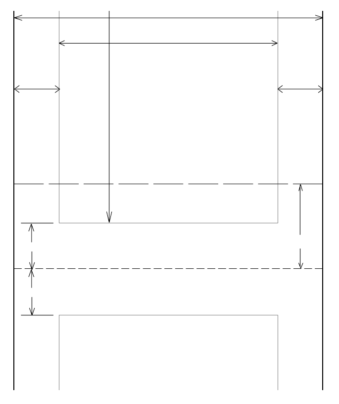
Control Code Definitions
—
Chapter 5
93
6820 Series 80-Column Printer User’s Manual
Page Layout for Fanfold Paper
Printable Area
The following illustration shows the printable area of the lower section of a
page of fanfold paper and the upper section of the next page. The Assured
Print Area is the best overall area in which to use for printing:
Abcdef...
...Xyz
Assured Print Area
Abcdef...
Assured Print Area
8 inches Max.
1inch
1inch
0.75 inch
(or more)
(area 2)
0.75 inch
(or more)
(area 2)
Paper width
...Xyz
Perforation
55 lines max. (at 1/6” line spacing)
(area 1)
(area 1) 1.8333 inches (11 lines)
Paper End Detection Position
(area 3)
Generally, you should leave a 1-inch margin at both the top and the bot-
tom of the page. This provides for a margin of six lines at 1/6 inch line
spacing. Even though printing in area 1 (before or after the perforation)
may be possible, you should keep in mind that paper feed precision is reli-
able only within the Assured Print Area.
Control Code Definitions
Chapter —
5
94 6820 Series 80-Column Printer User’s Manual
However, consider the following:
SThe top and bottom margins are represented by Area 1,asshowninthe
previous illustration. The top margin is defined as the distance between
the top edge of the paper and the first row of printed characters. The
bottom margin is defined as the distance between the last row of printed
characters and the bottom edge of the paper.
SThere is a possibility that printing can start within one line below the
perforation and printing could continue beyond the Assured Print Area,
however paper feed precision is only reliable with top and bottom mar-
gins of approximately one inch. Basically, you should consider there are
only 55 lines available for reliable printing.
SThe left and right margins are represented by Area 2. For reliable print-
ing, use a margin of at least 0.75 inch at the left and right edges of the
paper.
Paper End Detection
The Paper End Detection line shown in the previous illustration represents
the point at which the Paper Out sensor detects the bottom edge of the pa-
per.
Area 3 represents the the distance between the the Paper End Detection
position and the bottom edge of the page.
Once the last page of the fanfold paper stack is in the printer, and the print
head has advanced past this Paper End Detection line, printing is no longer
reliable.
Also, once the bottom end of the last page has advanced through the print-
er, past the spring plate along the front of the platen, the paper should not
reverse back through the printer, because the printer could jam and cause
paper feed problems. Design applications to prevent any reverse paper feed
from occurring after the Paper Out sensor has detected the bottom edge of
the paper.

956820 Series 80-Column Printer User’s Manual
Bluetooth Adapter
6
This chapter provides general information and configuration information
about the Bluetooth adapter that you may have upgraded to for your 6820
Printer.
Bluetooth Adapter
Chapter —
6
96 6820 Series 80-Column Printer User’s Manual
About the Bluetooth Adapter
The Bluetooth adapter connects to an internal serial port of the 6820
Printer, providing serial print data over a transparent Bluetooth link, run-
ning a Serial Port Profile (SPP).
Once your 6820 Printer is upgraded to Bluetooth with this adapter, the
6820 Printer no longer supports NPCP (Norand
R
Portable Communica-
tions Protocol), and instead prints using the Epson DTR mode. Printing is
primarily accomplished over a Bluetooth link using the SPP protocol with
a 700 Series Computer. If the relevant printer configuration allows it, a
700 Series Computer in a terminal holder charges normally.
The Bluetooth adapter allows for four states or modes to be available. Each
state is dependent upon either the pin states on the terminal holder con-
nector or the programming connector on the adapter described later.
State State/mode HHC_A/B pin HHC_DTR pin Comments
1Bluetooth Printing 0 0 Bluetooth printing/Bluetooth self-test
2Pass-through printing 0 1 Printing from 700 Series or CK60 Handheld
Computers allowed to pass-through the Blue-
tooth adapter transparently.
3Bluetooth Reconfiguration 1 0 Reconfiguring Bluetooth module via 700 Se-
ries or CK60 Handheld Computer
4Bluetooth programming
cabled
X X Programming Bluetooth module via program-
ming cable
SState 1 — In addition to allowing normal Bluetooth printing, this state
also allows for a 700 Series or CK60 Handheld Computer in the termi-
nal holder to perform a Bluetooth self-test.
SState 2 is a Transparent Pass Through mode available for all 700 Series
and CK60 Handheld Computers. During this mode, the Bluetooth
module is shut down and does not communicate.
SState 3 (Bluetooth reconfiguring using a 700 Series or CK60 Handheld
Computer). This state is unavailable when a 700 Monochrome Com-
puter is used, since the A/B pin is unavailable.
SState 4 allows for programming the Bluetooth module via its SPI pins.
This state is also used for manufacturing tests. To be in this state, the
700 Series or CK60 Handheld Computer must not have an open termi-
nal holder COM port and the specially designed programming adapter
must be engaged.

Bluetooth Adapter
—
Chapter 6
97
6820 Series 80-Column Printer User’s Manual
Bluetooth Adapter Indicators
The interfaces on the Bluetooth adapter that allow for the different modes
are detailed below:
700 Series or CK60 Handheld Computer to 6820 Pass Through
Note: Pass through printing requires shutting down the Bluetooth portion
of the adapter. To reenable Bluetooth functionality after you finish pass
through printing, press a button on the control panel to wake the printer.
When DTR on the 700 Series or CK60 Handheld Computer is set, the
adapter board automatically opens a path between the 700 Series or CK60
Handheld Computer and the 6820 Transition/DC Board and powers
down the Bluetooth module. Testing the DSR pin to reflect DTR allows
the mobile computer to differentiate between a Bluetooth-equipped termi-
nal holder and a non-Bluetooth equipped terminal holder.
700 Series or CK60 Handheld Computer to Bluetooth Module
Communication Interface
The Bluetooth adapter allows a 700 Series or CK60 Handheld Computer
to communicate directly with the Bluetooth module under two circum-
stances.
SWhen the configuration settings of the Bluetooth module are to print.
SWhen the Bluetooth module requires reconfiguration.
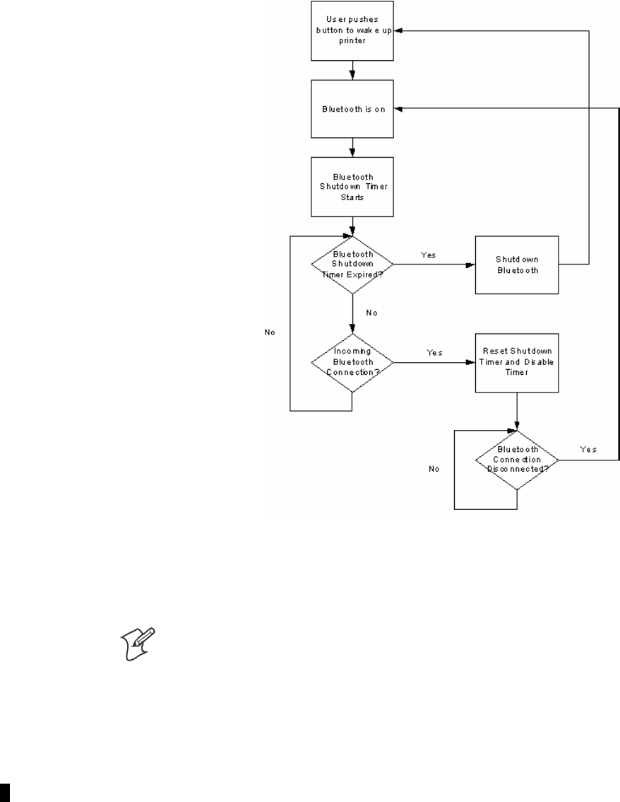
Bluetooth Adapter
Chapter —
6
98 6820 Series 80-Column Printer User’s Manual
Bluetooth Adapter Power Management Flow
Bluetooth Power Management Flow Diagram
Radio Power On/Off Mechanism
Note: The shutdown timer configuration is addressed in Appendix A,
“Bluetooth Configuration Commands.”
As stated earlier, the Bluetooth adapter, including the Bluetooth radio
shuts down after a configurable time (default is two hours). To wake the
Bluetooth adapter, the 6820 Printer is powered on by any button push on
the printer control panel. There are two ways to shutdown the Bluetooth
module power:
SA 700 Series or CK60 Handheld Computer initiates a pass through
mode, or
SThe Bluetooth module sends a shutdown signal after a configurable
amount of time. Default is two hours.
Bluetooth Adapter
—
Chapter 6
99
6820 Series 80-Column Printer User’s Manual
Security
The adapter complies with Bluetooth 1.1 specification, including bonding
for authentication and enabling encryption.
Persistent Storage
These settings do not reset after a cold-boot is performed on the printer:
SBluetooth Bonding Enablement/Disablement
SBluetooth Encryption Enablement/Disablement
SBluetooth Passkey
SBluetooth Bonding List (Link Keys)
SBluetooth Device Name
SBluetooth Class of Device
SDiscoverable setting
SConnectable setting
SRadio Shutdown Timer Timeout (default two hours)
System Behavior/Software Considerations
SDiscoverability — The default mode is Discoverable. When configured
to be Discoverable, the adapter is discoverable at all times, except when
an active Bluetooth connection exists.
SConnectability — The default mode is Connectable. When configured
to be Connectable, the printer is connectable at all times, except when
an active Bluetooth connection exists.
SLink Loss — The 6820 Bluetooth adapter is able to recover from bro-
ken Bluetooth connections, including out of range, interference, power
failure, or any other condition resulting in a broken connection. It re-
turns to its previous Discoverable/Connectable state after a lost connec-
tion.
SMaster/Slave — Printer shall participate in a Bluetooth connection as
the Slave device.
SThe Class of Device is 0x040680 which translates to a Service Class of
Rendering, a Major Device Class of Imaging, and a Minor Device Class
of Printer.
SThe 6820 Bluetooth includes an SDP record that allows the printer to
report an SPP instance with a Service Name of “Wireless Printer”.
SThe default Bluetooth Device Name is 6820-DDEEFF, where
DDEEFF matches the respective portion of the Bluetooth Device Ad-
dress (AA:BB:CC:DD:EE:FF). If the printer the adapter is connecting
to is known, the Device Name is changed to 6820-SN, where SN is re-
placed with the serial number of the 6820.
SThe 6820 Bluetooth adapter can save 16 link keys across cold boots.
Link keys are saved in a circular list. The 17th link key replaces the first,
the 18th replaces the 2nd, and so on.

Bluetooth Adapter
Chapter —
6
100 6820 Series 80-Column Printer User’s Manual
Remote Configuration
You can query the following items:
SDiscoverable State [Get/Set]
SConnectable State [Get/Set]
SBondable State [Get/Set] (Authentication)
SEncryption State [Get/Set]
SDevice Name [Get/Set]
SDevice Address[Get]
SClass of Device[Get/Set]
SService Name [Get/Set]
SBluetooth Profile [Get]
SBluetooth Passkey [Set] (Getthefactthatitisset)
SRadio Shutdown Timeout
Bluetooth Performance
SRange — Operating range is expected to range from a minimum separa-
tion of 10cm to over 10m with a 700 Color or CK60 Handheld Com-
puter.
SLink Loss can occur when going in or out of range while communicat-
ing with other Bluetooth devices. Degradation in range and data
throughput is expected when in automobile cabins or when involved in
intermittent loss of line-of-sight (communications across a busy road).

Bluetooth Adapter
—
Chapter 6
101
6820 Series 80-Column Printer User’s Manual
Diagnostics Capabilities
Radio Self Test
The Bluetooth radio settings are available to a user. The 6820 Bluetooth
adapter sends a print out of Bluetooth information to the printer upon re-
ceiving a message from a 700 Series or CK60 Handheld Computer in a
terminal holder.
The self-test appears like the following.
6820 Bluetooth Adapter
Firmware: Version YYYY MMDD HHMM
Bluetooth Configuration:
Device Address: 0002371A0FD3
Device Name: 6820-9843252
Discoverable: Yes
Connectable: Yes
Authentication: No
Encryption: No
Passkey: Not Applicable (or Key present if Authentication is enabled)
Stored Link Keys: 2 of 16
Power Management:
Shut Off Timer: 120 minutes
The Passkey entry either states “Not Applicable” or “Key Present” depend-
ing on the Authentication state. Tabs ensure items line up in columns as
showninthisexample.
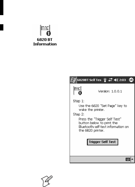
Bluetooth Adapter
Chapter —
6
102 6820 Series 80-Column Printer User’s Manual
Applications
A 6820 Bluetooth Information application that prints the Bluetooth self-
test information on the 6820 Printer can be installed on your 700 Series or
CK60 Handheld Computer. Do the following to use this application:
1Insert the 700 Series or CK60 Handheld Computer in the terminal
holder on the 6820 Printer.
2From the 700 Series or CK60 Handheld Computer, tap Start >Pro-
grams >the6820 BT Information icon.
3On the 6820 Printer, press the SET PAGE button on the printer con-
trol panel to “wake” the printer.
4From the 6820BT Self-Test screen, tap Trigger Self Test to print the
information.
Note: A GUI tool for Adapter configuration is not a deliverable of this
product. The adapter is configurable via the Bluetooth Configuration
Commands. See Appendix A, “Bluetooth Configuration Commands”forde-
tails.

Bluetooth Adapter
—
Chapter 6
103
6820 Series 80-Column Printer User’s Manual
System Qualification
Operation Resilience
Normal operation of the Bluetooth system is available in environments
with radio backbones, including 802.11b, Spectrum 24, and OpenAir
technologies.
Environmental Specifications
Temperature
The device must operate from -20°C to +60°C, and must be capable of
non-operating storage from -30°C to +70°C.
Test Range Comments
Operating Cold to Hot Transition –20° C to 50° C External condensation allowed, internal prohibited
Operating Hot to Cold Transition 50° C to –20° C Speed shall not degrade
Humidity 5% to 95% RH non-condensing
Operating 90% 25 – 60° C (no condensation)
Storage 90% 25 – 60° C (no condensation)
Altitude
–100 to 5000 meters
Vibration
Quasi-Random 3 axis 12g RMS, for four hours
Dynamic Induced Shock 20g on 3 axis
Operating 1G5Hzto80Hz
Storage 3G5Hzto80Hz
When packed Frequency 5 to 55 Hz
Acceleration 2G
Sweep 10 minutes (half cycle)
Duration 1 hour
Directions x, y, and z
No external or internal damage should be found after the vibration test,
and the unit should operate normally.
Unpackaged Drop
2 feet to concrete
Terminal Inspection
Minimum of 30,000 insertions for the terminal holder.

Bluetooth Adapter
Chapter —
6
104 6820 Series 80-Column Printer User’s Manual
Safety/Regulatory/Agency Requirements
The Bluetooth adaptor within the 6820 Printer, including all options,
must meet these electrical safety requirements for Information Technology
Equipment. The test configuration must include a portable computer con-
nected to the 6820 Printer, continuously printing the letter “H”. At least
6dB of margin below the relevant limits must be demonstrated.
Product Safety UL Listed per UL 1950 / UL 60950 (Printer and AC power supply) CSA C22.2, No. 950
TUV/GS License per EN 60950 (Printer, ac power supply)
CB Report for EN 60950 covering all country deviations (Printer, ac power supply)
UL 2089 (for cigarette lighter-style adapters)
Vehicle Power Interfaces SAE J1113 or ISO 7637
EMC
Digital device radiated
and conducted emissions
FCC Class B (US); Industry Canada ICES-003 Class B (Canada)
CISPR 22 Class B, including telecom port conducted (Europe)
AS/NZS 3548 (Australia/New Zealand); CNS 13438 (Taiwan)
EN 55024 Immunity IEC 61000-4-2 Electrostatic Discharge
(Europe) IEC 61000-4-3 Radiated RF Field
IEC 61000-4-4 Electrical Fast Transients
IEC 61000-4-5 Surge
IEC 61000-4-6 Conducted RF
IEC 61000-4-8 Magnetic Field
IEC 61000-4-11 Voltage Dips and Interrupts (AC printers only).
AC power supply
(Europe)
IEC 61000-3-2 (per Amendment 14) Class A if under 70 Watts loaded to 90% of rated
value, Class D if over 70 Watts loaded to 90% of rated value
IEC 61000-3-3 Voltage Fluctuation and Flicker.
Radio Type Approval Bluetooth Radio - Modular radio approval is required. BT SIG approval is not mandatory
but BT SIG GAP and SPP conformance is a prerequisite.
FCC Part 15.247 (US)
RSS-210 (Canada - indoor operation, unlicensed. Outdoor operation IF restricted to
2.450-2.4835GHz)
RSS-139 (Canada - indoor/outdoor operation, licensed. 2.400-2.4835GHz)
RSS-102 (Canada) - RF Exposure/SAR. Keep antennas more than 8 inches from operator
to avoid SAR testing
EN 300 328-1 & -2; EN 300 489-1 & 17 (Europe).
SCT (Mexico)
Additional Approvals IEC950 2nd Edition, 4th Amendment or IEC 60950 3rd Edition, resulting in a GS Mark
and a CB Report addressing all country deviations
S Mark for Argentina for any device connecting directly to the AC mains·
CCIB Approval for China for any device connecting directly to the AC mains·
Mexico NOM 19 as applicable

Bluetooth Adapter
—
Chapter 6
105
6820 Series 80-Column Printer User’s Manual
Default Configuration
Bluetooth Authentication Off
Discoverable True
Connectable True
Class of Device 0x040680
Service Name Wireless Printer
Device Name 6820-DDEEFF
Baud Rate 19,200
Data Bits 8
Stop Bits 1
Parity None
Handshaking Hardware
Radio Shutdown Timeout 120 Minutes
Bluetooth Adapter
Chapter —
6
106 6820 Series 80-Column Printer User’s Manual

1076820 Series 80-Column Printer User’s Manual
Troubleshooting and
Diagnostics
7
This chapter helps you correct printing problems that may occur. If you
experience a printing problem, you can perform several tests to find and
possibly cure the problem.
This chapter also contains troubleshooting strategies for the 6820 Printer,
and a detailed listing of the Diagnostics Information table.
Troubleshooting and Diagnostics
Chapter —
7
108 6820 Series 80-Column Printer User’s Manual
Checking the Power Source
Press any key on the printer control panel. If there is power, the power in-
dicator (green LED) turns on and the print head moves to its starting posi-
tion. If the printer emits beeps and any of the other indicators light up or
flash, observe the number of beeps and indicator flashes and refer to the
Printer Failure Indicators table on page 119.
If there is no reaction from the printer after you press a key on the control
panel, or only the green power light blinks, verify that the power cables are
properly connected between the printer mechanism and its power source
(internal battery, vehicle cable, or ac). If none of these steps “wake” up the
printer with the problem, then you need to return the printer for service.
SInternal battery: Check the battery and its cable by installing into
another known-good printer.
SVehicle cable: Attach the printer in question to another vehicle power
cable.
SAC power: Plug the printer into another outlet.
Self-Test Failure
If a partial report generates and a printer error occurs during printing,
refer to the table on the next page for troubleshooting help.
If the printer does not generate a report:
SThere may be a printer failure, refer to the troubleshooting table on the
next page for possible solutions.
SThere may be a power failure, check the power source (internal battery,
charge cable, or ac adaptor).
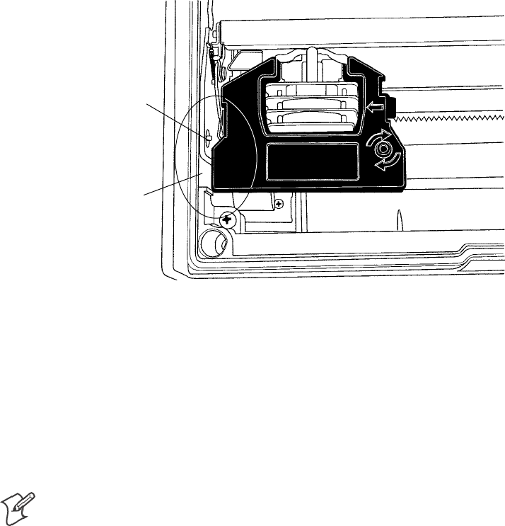
Troubleshooting and Diagnostics
—
Chapter 7
109
6820 Series 80-Column Printer User’s Manual
Printer Mechanism Alignment
If head jams are occurring, the alignment of the printer mechanism may
need correction.
Open the printer top cover, then install a ribbon cartridge (see page 16)
and position the print head to the far left toward the green thumb wheel.
Observe the area between the print head and the printer cavity (circled in
the following illustration). If the ribbon cartridge touches the pivot frame
or press nut, the printer mechanism needs realignment.
Press nut
Pivot frame
This illustration shows the print head to the far left in the printer.
1Loosen the four screws that hold the mechanism in place using a Phil-
lips screwdriver (see the following illustration).
2Realign by pushing the printer mechanism to the right, away from the
green thumb wheel.
3Push on the right side of the printer mechanism to the back as far as it
will go.
Note: In this position, the right back edge of the printer mechanism may
touch the pivot frame. The left side must NOT touch the pivot frame.
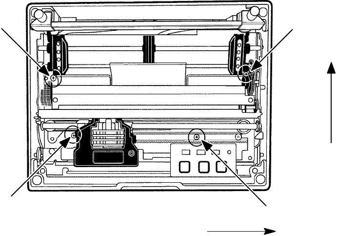
Troubleshooting and Diagnostics
Chapter —
7
110 6820 Series 80-Column Printer User’s Manual
4Hold the printer mechanism in this position and securely tighten the
screws in the sequence shown.
Push mechanism to the right.
Push mechanism
to the back
1TopRight
2 Bottom Left
3Top
Left
4 Bottom Right
The four position screws that hold down the printer mechanism are shown in this illustration. Be
sure to do the screws in the order given.
The position of the print head should NOT touch the pivot frame or press
nut. If the print head does touch the pivot frame or press nut, return the
printer for hardware repair.
Communications or Host Computer
The self-test report can verify that the communications protocol options
selected for the printer match those expected by the host computer. If
these options do not match, then reconfigure the printer using the control
panel configuration modes.
If the protocol options do match, then the data communications cable
may be defective. Verify that the cable is working by substituting a new
cable or host computer. Also, check the computer vehicle dock.
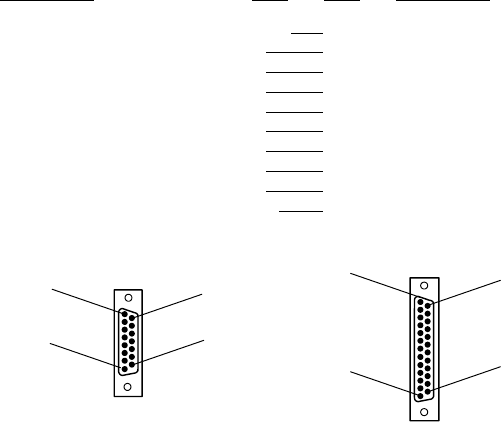
Troubleshooting and Diagnostics
—
Chapter 7
111
6820 Series 80-Column Printer User’s Manual
Communications Pin-Out Configurations
Below are common cable configurations between a mobile computer or a
dock and the printer:
Signal Name Pin # Pin # Signal Name
Chassis Ground shell 1 NC (No Connection)
Charge Input 8 9 HHC_CHARGE
SG (Signal Ground) 9 7 GND
DSR (Data Set Ready) 7 6 DTR
DTR (Data Terminal Ready) 2 20 NC
CTS (Clear To Send) 6 5 RTS
RTS (Ready To Send) 3 4 CTS
RXD (Receive Data) 5 3 TXD
TXD (Transmit Data) 4 2 RXD
Dock_A/B_SW NC 12 Term A/B
13
Mobile Computer
Wall Mount Printer or
Remote Mount Terminal Holder
25-Pin DSUB Male
1
25
14
8
15-Pin DSUB Male
15
9
1
shield
15-Pin to 25-Pin Cable P/N: 216-605-XXX
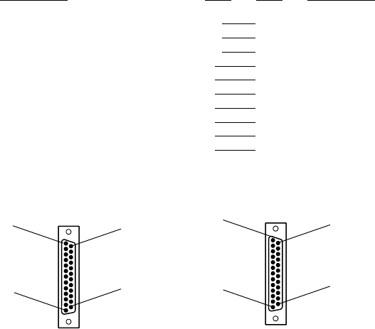
Troubleshooting and Diagnostics
Chapter —
7
112 6820 Series 80-Column Printer User’s Manual
PC Wall Mount Printer
Signal Name Pin # Pin # Signal Name
DTR (Data Terminal Ready)* 20 20 NC (No Connection)
RC (Receive Carrier) 17 17 NC
TC (Transmit Carrier) 15 15 NC
DCD (Data Carrier Detect) 8 8 NC
SG (Signal Ground) 7 7 GND
DSR (Data Set Ready)* 6 6 DTR
CTS (Clear To Send) 5 5 RTS
RTS (Ready To Send) 4 4 CTS
RXD (Receive Data) 3 3 TXD
TXD (Transmit Data) 2 2 RXD
* Signals are not available on the 6100 Dock
13
25-Pin DSUB Male25-Pin DSUB Female
1
13 1
14
25
25
14
25-Pin to 25-Pin Cable P/N: 216-771-XXX
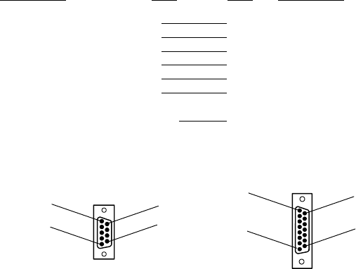
Troubleshooting and Diagnostics
—
Chapter 7
113
6820 Series 80-Column Printer User’s Manual
Signal Name Pin # Pin # Signal Name
TXD (Transmit Data) 3 4 RCT
RXD (Receive Data) 2 5 TXD
RTS (Ready To Send) 7 3 CTS
CTS (Clear To Send) 8 6 RTS
DSR (Data Set Ready) 6 7 DTR (Data Terminal Ready)
SG (Signal Ground) 5 9 GND
Chassis Ground shell shell Chassis Ground
8 Terminal Charge out to computer...............
PC Printer
shield
1
15-Pin DSUB Female9-Pin DSUB Female
1
5
6
9
9
15
8
9-Pin to 15-Pin Cable P/N: 226-016-XXX
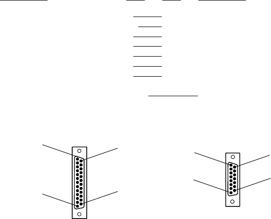
Troubleshooting and Diagnostics
Chapter —
7
114 6820 Series 80-Column Printer User’s Manual
Signal Name Pin # Pin # Signal Name
TXD (Transmit Data) 2 4 RXD
DTR (Data Terminal Ready) 20 2 NC (No Connection
RTS (Ready To Send) 4 3 CTS
RXD (Receive Data) 3 5 TXD
CTS (Clear To Send) 5 6 RTS
DSR (Data Set Ready)* 6 7 DTR
SG (Signal Ground) 7 9 GND
open shell
* Signal is not available on the 6100 Dock
13
Dock Printer w/ 6210 Terminal Holder
25-Pin DSUB Male
1
25
14
8
15-Pin DSUB Female
15
9
1
shield
25-Pin to 15-Pin Cable P/N: 226-162-XXX
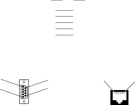
Troubleshooting and Diagnostics
—
Chapter 7
115
6820 Series 80-Column Printer User’s Manual
Pin # Pin #
76
55
33
22
81
PC Printer
9-Pin DSUB Male
5
1
9
6
RJ-11 Jack
16
Data Communications Cable P/N: 226-270-XXX

Troubleshooting and Diagnostics
Chapter —
7
116 6820 Series 80-Column Printer User’s Manual
The printer has a 25-pin connector with the following pinout designations
and signal mnemonics:
Printer Communications Connector Pin-Outs
15-Pin
D-Sub
25-Pin
D-Sub Signal Name Type I/O Description
1NC NC – – – – – – NC (No Connection)
220 NC ––– ––– NC
34 CTS (Clear To Send) RS-232 IN Wake up
42RXD (Receive Data) RS-232 IN Printer’s RxD
53 TXD (Transmit Data) RS-232 OUT Printer’s TxD
65RTS (Ready To Send) RS-232 OUT IrDA baud rate select
76 DTR (Data Terminal Ready) RS-232 OUT IrDA baud rate select
89HHC_CHARGE POWER OUT 7.5–15 V, up to 1 A per contact
97 GND POWER SG (Signal Ground)
10 NC NC ––– –––
11 11 IO_SENSE 0–5 V
ANALOG
IN Analog input signal for I/O board type
detection. Normally tied to +5 V.
NC 12 DOCK_A/B_SW ––– IN Bluetooth Adapter configuration signal
12 18 IOB_RESET TTL OUT Signal to hold I/O board in reset.
13 25 TTL_POWER POWER OUT Power for I/O board logic (never shuts off)
14 NC NC ––– –––
NC NC NC ––– IN Switched 5 V from computer.
NC NC V_IN ––– ––– Unswitched input power from printer.
Troubleshooting and Diagnostics
—
Chapter 7
117
6820 Series 80-Column Printer User’s Manual
Troubleshooting
The printing system is composed of four basic components: Printer, Com-
puter, Power Source, and Communications. Any one of these components
can prevent the printer from functioning properly.
Verifying the Printer Components
Power Source Verification
Start by verifying that power is available at the printer. Visually inspect the
control panel to verify that the power indicator (Green LED) is lit. If it is
not, press the SET PAGE button and note if the power indicator lights up.
If it does, the power system is all right. If it does not, press the printer reset
button. If the power indicator still does not light, check the power cable,
by connecting it to a different printer. If the power indicator works on the
new printer, then the cable is all right, and the printer that was originally
connected is suspect. If it does not light, then the problem is most likely
the cable or the power source. Depending on the results, either replace the
cable or return the printer for service.
Printer Verification
If the power indicator works properly and the printer still does not print,
then printer errors are noted. If any indicators light when the SET PAGE
button is pressed, or the printer beeps, then refer to the Printer Failure In-
dicators table to determine the problem.
If none of the listed conditions are indicated by the beep codes and LEDs,
yet the printer does not perform properly, then perform a printer self-test.
Press and hold (for several seconds) the FORM FEED and SET PAGE
buttons at the same time, until the printer beeps and all indicator lights
come on. The lights change throughout the test, as it progresses.
At the end of the self-test, the printer generates a report. This report veri-
fies the following: errors detected during self-test, the error history, and the
communication configuration. If the printer self-test report does not print,
then reset the printer. If the report does print after resetting, then the
printer is all right and the reason the printer does not respond to host com-
puter print requests is probably communications or host computer related.
If the report is partially completed, and a printer error occurs during the
printing of self-test, refer to the Printer Failure Indicators table for the
cause of the printer failure.
Perform a Power On Self-Test (POST) to test for errors either by resetting
the printer or powering it up. If any errors, audible error codes, along with
indicator light status, are produced during POST (see the POST Error
Codes table).
If the POST completes without error, try the printer self-test again. If
self-test prints correctly this time, but the printer does not respond to the
host computer, then the problem may be communications or host com-
puter related. If errors are encountered during POST, contact Customer
Support for assistance.
Troubleshooting and Diagnostics
Chapter —
7
118 6820 Series 80-Column Printer User’s Manual
Communications / Host Computer Verification
Use the self-test report to verify that the communications protocol options,
selected at the printer, match those expected by the host. If they do not
match the expected results, reconfigure the printer using the control panel
configuration modes described below in the Configuration part of this
chapter.
If the protocol options match, then the communications cable may be de-
fective. To determine if the cable is working, substitute a new cable. If the
host computer is suspect, substitute a different host computer. A defective
computer dock might be another possibility.
Error Handling
Printer Errors are divided into several classes: POST errors, Run-Time er-
rors, and Fatal errors (consisting of flash write errors and EEPROM block
errors).
Run-Time Errors
Run-time errors can occur during the course of printing. These errors are
displayed on the LEDs, along with beep sequences. This causes the printer
to stop printing and enter an error state. Then beep sequences are emitted,
LED codes are displayed, the error status may be sent to the host (depend-
ing on the protocol), and the printer goes into suspend mode.
The printer exits from the suspend mode when the user presses one of the
keyboard keys or communications is resumed from the host. The printer
also places the print head in its home position and attempts to recover
from the error condition. Until the error condition is corrected, the error
procedure does not end, and the error state is not removed.
For PAPER OUT errors, the user must load paper and press the SET
PAGE button before printing begins. The paper may be loaded to the top
of form, either manually or automatically, by pressing the FORM FEED
button to wake the printer from suspend mode.

Troubleshooting and Diagnostics
—
Chapter 7
119
6820 Series 80-Column Printer User’s Manual
For a listing of run-time errors, refer to the following table.
Printer Failure Indicators
Sets of Beeps
PAPER
OUT
HEAD
JAM
LOW
BATT Meaning
1 beep OFF OFF ON 12V under voltage fault (Low Battery)
1 set of 2 beeps OFF OFF 2blinks 12V over voltage fault (Input Voltage too high)
1 set of 3 beeps OFF OFF 3 blinks 24V under voltage fault (internal power supply failure)
1 set of 4 beeps OFF OFF 4blinks 24V over voltage fault (internal power supply failure)
1 set of 13 beeps OFF OFF OFF Configuration error
2 sets of 2 beeps OFF 2blinks 2blinks Print head over temperature
2 sets of 3 beeps ON OFF OFF Paper Out
2 sets of 4 beeps OFF ON OFF Head Jam
2 sets of 5 beeps 5 blinks 5 blinks 5 blinks Paper feed current fault (Possible paper jam or feed motor failure)
3 sets of 2 beeps 3blinks OFF 3blinks Print head over current (Print head failure)
3 sets of 4 beeps OFF 3 blinks OFF Home switch failure
4 sets of 2 beeps 4blinks 4blinks OFF Print head short (Print head failure)
4 sets of 4 beeps Erratic Erratic Erratic Flash write error
12 sets of 12 beeps OFF OFF OFF Operating System software failure
The most common errors consist of Paper Out, Low Battery, and Head
Jam. The other errors listed are of rare occurrences, but are provided for
good printer diagnostics in the event failures should occur.
Power-On Self-Test (POST)
When the printer is reset, it performs a POST to verify other reasons the
printer might be failing. Audible error codes, along with indicator light
status, are produced during POST if an error is encountered, as listed in
the POST Error Codes table.
A printer diagnostic cable, connected between the host computer and the
printer, is used during POST to: configure the printer, access printer diag-
nostics, update software, and install new fonts.
To install the diagnostic cable: connect the phone plug into the phone jack
on the printer, then connect the 9-pin DSub plug into the host computer.
After installing the diagnostic cable, reset the printer to initiate POST.
POST Errors
POST errors only occur after a push button reset, or an initial application
of power to the printer. After the reset button is pressed, the LEDs (on the
printer control panel) indicate the progress of POST. The first LED to
light should be the power indicator (Green LED). A single beep should be
heard immediately after this LED lights up to indicate the printer is active.

Troubleshooting and Diagnostics
Chapter —
7
120 6820 Series 80-Column Printer User’s Manual
During the course of POST, the other LEDs light to indicate progress
throughout the tests. If a POST failure is detected, the printer emits one of
the following printer LED error codes and beep sequences.
POST Error Codes
Long
Beep
Short
Beep
PAPER
OUT
HEAD
JAM
LOW
BATT Power Meaning
01 OFF OFF OFF ON Operational
00OFF OFF OFF OFF No Power
00 OFF OFF OFF ON Control program Initial Program Load (IPL) successful
00ON OFF OFF ON Diagnostic mode command check
00 ON ON ON ON Control program IPL
11OFF ON OFF ON Invalid CRC on boot block
12 OFF ON ON ON Invalid CRC on control program or program not found
14OFF OFF OFF ON Lower 64K RAM failure
14 OFF OFF ON ON Upper 64K RAM failure
15ON OFF ON ON Diagnostic flash memory check failed or is not initialized
15ON ON OFF ON Diagnostic memory write failure
After completion of the tests, all LEDs are turned off and there is an at-
tempt to place the head in the home position. Until the next time the
printer is reset and POST is performed, only run-time errors or fatal errors
are reported.
Fatal Errors
Two types of fatal errors exist: Flash Write Errors and Printer Configura-
tion Block Errors. These errors are extremely rare, but measures are built
into the printer diagnostics to track possible occurrences.
Flash Errors
Errors related to writing or erasing flash are critical errors. These critical
errors cause the printer to stop all processing and output an LED code and
a sequence of beeps. The LED code represents the address of the segment
that the error occurred on in octal notation. The octal digit changes every
four beeps until four octal digits have been output. Only four octal digits
are output since blocks are 256 bytes in size and flash can be addressed
with a total of 0x7ff blocks. Note that the segment address output is the
runtime address of the flash block and not the offset of the block within
flash. To obtain the block offset within the flash, subtract 0x800 from the
address output.
After the error code is processed, the printer enters suspend state. When
the printer resumes, the error again is output and suspend reentered. A re-
set is required to eliminate the error condition. Flash write errors may be
unrecoverable. If this is the case, the printer requires servicing by qualified
technicians.
Troubleshooting and Diagnostics
—
Chapter 7
121
6820 Series 80-Column Printer User’s Manual
EEPROM Configuration Errors
Errors related to an invalid configuration block (diagnostic block) produce
13 beeps once, and then the printer suspends. It continues to produce this
symptom, until the configuration block error is corrected. No LEDs light.
This error may be caused by a flash write error or merely lack of proper
printer configuration. If the error cannot be corrected by a reset of the
printer, then the printer needs to be serviced by a qualified technician.
Self-Test Function Descriptions
Self-test consists of the following functions.
Boot Block Program Verification
A CRC (Cyclic Redundancy Check) is performed on the bootblock pro-
gram. The calculated CRC is compared to the CRC embedded in the pro-
gram module.
Control Program Verification
A CRC is performed on the control program, which is loaded into writable
flash program memory. The calculated CRC is compared to the CRC em-
bedded in the program module. The results of this test are printed on the
self-test report.
Font Module Verification
A CRC is performed on the font modules, which are loaded into writable
flash font memory. The calculated CRC is compared to the CRC em-
bedded in the program module. The results of this test are printed on the
self-test report.
A2D Check
Current reading of the A2D sources are performed, and the results are
printed on the self-test report.
Nonvolatile Diagnostic Memory Verification
A CRC is performed on the area of the nonvolatile diagnostic memory
that has a CRC over it. The results of this test are printed on the self-test
report.
Nonvolatile Diagnostic Memory Update
The nonvolatile diagnostic memory is updated from the nonvolatile diag-
nostic memory data shadowed in memory.

Troubleshooting and Diagnostics
Chapter —
7
122 6820 Series 80-Column Printer User’s Manual
Detailed Printer Self-Test
Self-test is user-selectable, verifies printer functions, and provides reporting
of printer diagnostics. It performs a series of internal diagnostics and prints
the results. When self-test begins, the beeper sounds for half a second and
all LEDs turn on for half a second.
Initiating Self-Test
Self-test is initiated by simultaneously pressing both the LINE FEED and
SET PAGE buttons on the control panel, while the printer is idle or
asleep.
Terminating Self-Test
Self-test can be terminated manually, during the test, by simultaneously
pressing both the LINE FEED and SET PAGE buttons.
Self-Test Report
Note: This method is recommended for determining printer functionality.
A self-test is equivalent to a warm start. Both are performed when you si-
multaneously press the FORM FEED and SET PAGE buttons on the
control panel for a few seconds. Release these buttons when the printer
beeps and all indicators are lit. If the buttons are held too long, the self-test
will not happen and the printer will form-feed one page.
As the self-test progresses, the indicator lights change. Internal tests are
performed and a 2-page report is printed. This report provides helpful in-
formation in diagnosing and troubleshooting printer problems.When the
self-test is performed, the following actions occur:
Note: to abort the self-test can by pressing a button while the report is printing.
SAll LEDs are turned on to verify the lights work
SA 600 ms beep is emitted to verify the beeper works
SLEDs flash individually to show progress during internal tests
SCurrent voltage and ambient temperature are obtained
SValidity of diagnostic block program is checked
SValidity of BootBlock program is checked
SValidity of control program is checked
SValidity of loaded fonts is checked
SLEDs turn off
SSelf-test report is printed
Printer capability is diagnosed by printing the report. Device errors are dis-
played on the LEDs and emitted by the beeper. The printer then does a
warm reset (soft reboot) upon error or completion of the self-test report.

Troubleshooting and Diagnostics
—
Chapter 7
123
6820 Series 80-Column Printer User’s Manual
First Page of Self-Test
The self-test report is divided into sections. Refer to pages 124 and 125 for
a sample printout.
The printer model number is given on line 1 (first line). This identifies the printer type used, in this case the 6820.
The 8-digit serial number of the printer is listed on line 4 under the “Serial#” heading on line 3. The serial number is
also on the inside of the printer. In portable printers, raise the printer mechanism to look for the number on the inside
back wall.
“Battery Voltage,” on line 13, gives the input voltage sampled at the beginning of the self-test. The input range must
be between 7.5 and 15 volts. The input voltage must be greater than 10.5 volts to charge the internal battery. At 7.5
volts or less, the LOW BATT LED is turned on and the printer goes to sleep immediately. Apply external power to
wake the printer to print. At 10.5 volts or less, the LOW BATT light comes on but the printer still prints.
The “Auto Feed” setting, on line 16, is a configurable item. “CR” Carriage Return means no auto linefeed. This is the
most common setting for applications using NPCP. “CR+LF” means a linefeed will be added to each CR. This setting
can produce double-spacing of reports. See page 32 for information on changing this configuration.
The “Interface Mode” setting, line 17, lists the interface protocol for the printer. The typical setting is NPCP. Others
include DTR with no, odd, or even parity, and IrDA. See page 32 for additional information.
“Bit Rate” on line 18, lists the baud rate for the printer. Most application software autobauds so you do not have to
select it. Bit rate is commonly set to 19200 (19.2K) or 9600 bps. See page 33 for additional information.
“A2D History,” lines 21 through 25, is the history for voltage measurements and temperature measurements, as re-
corded by the printer.
“Head Jam History” on lines 26 through 29, gives information on head jams. If the printer is having frequent head
jams, these lines can assist in determining the problem.
Under the “Home” header, if “Err” is listed, then the home position LED sensor has failed.
“Command” tells which printer command was executed when the head jammed.
“Direction” tells which way the head was moving, “left” toward home and “right” away from home. Home posi-
tion is at the extreme left, toward the green thumb wheel.
“Speed” is the acceleration speed of the print head when the jam occurred.
“Step” is the acceleration step at the jam. “0” means no steps were taken, “15” means all steps were taken. “1–14”
means printer jammed during acceleration or deceleration.
“Temp” is the ambient temperature at the last head jam. The temperature is listed in Celsius.
“Position” of carriage at the jam in 1/720 inches = 12 * step position. Divide the number by 12 to get the step
position. There are 512 steps across the page. If it is jammed at position 0, check the printer mechanism align-
ment. If it is jamming in the middle, it is more likely a dirty ribbon or obstruction in the print head’s path.
“Head Dot Pattern,” line 37, is printed to verify the individual dot wires. There should be nine dots. If some are miss-
ing, it could be a print head failure or a circuit board failure.

Troubleshooting and Diagnostics
Chapter —
7
124 6820 Series 80-Column Printer User’s Manual
(continued)
“Error Log” information appears on lines 38–43. This information is cleared after every self-test. This information is
very helpful in determining problems.
“PE” # of paper jams while feeding paper
“HJ” #ofheadjamswhileprintheadismoving
“12Vu” # 12-volt under voltage
“12Vo” # 12-volt over voltage
“24Vu” # 24-volt under voltage (Head/motor voltage)
“24Vo” # 24-volt over voltage
“Home” # Home detect errors (typically caused by paper scraps or circuit failures)
“Temp” Unused
“OverC” # Head over current errors (typically caused by a bad print head)
“HeadS” # Head driver short errors (typically caused by circuit failures)
“Fault” # Paper feed motor over current errors (Excess current in paper feed motor could indicate circuit failure)
“ADErr” # A2D conversion failures
“EEErr” # EEPROM write failures to diagnostic block
“Dlink” # Software memory errors (Corruption in internal memory)
“Llink” # Software memory errors
All other values are informational only. Remember that these values are
cleared after the self-test.
Sample First Page of Self-Test
Note: Lines 15–18 are factory-default printer settings. Take note of these
lines when reading the self-test report.
yyyyyyyyyyyyyyyyyyyyyyyyyyyyyyyyyyyyyyyyyyy
1NP6820
2Copyright 1997, 1998, Intermec Technologies Corporation. All Rights
Reserved.
3Serial# MFG Date Hardware Check Repairs Svc Date
412345678 yy/mm/dd ddd-ddd-ddd/dddd (TOP) GO/NG 00 yy/mm/dd
5ddd-ddd-ddd/dddd (MLB)
6ddd-ddd-ddd/dddd (PS)
7ddd-ddd-ddd/dddd (IOB)
8Revisions:..........0000000000303100
9Bootblock: NPBB6820.MOD - Version XX.XX XXXX XXXX GO/NG
10 Control Program: npfl6820.mod - Version XX.XX XXXX XXXX GO/NG
11 Font Module: nftxxxxx.mod - Version XX.XX XXXX XXXX GO/NG
12 Font Module: nftxxxxx.mod - Version XX.XX XXXX XXXX GO/NG
13 Battery Voltage: 012.34 Low...../....High
14 Total Pages: 123456
15 Zero Font Style:
16 Auto Feed: CR
17 Interface mode: NPCP
18 Bit Rate: 19200
19 Cold Starts: 00024
20 Warm Starts: 00050

Troubleshooting and Diagnostics
—
Chapter 7
125
6820 Series 80-Column Printer User’s Manual
21 A2D History
22 Curr Low High Min Max Error Page Count
23 24v: 024.00 023.21 023.91 023.21 024.51 027.21 00401 00021
24 12v: 012.55 010.91 013.51 010.90 014.50 8.71 00401 00021
25 Temp: 023 -020 055 -021 060 000 00401 00021
26 Head Jam History
27 Total Head Jams: 00186
28 Home Command Direction Speed Step Temp Position Page
29 Print Left Const 010 -010 01440 12345
30 NPCP History
31 Disc Addr Parity IFTS Seq CRC Frame Bind IPLDU
32 12345 12345 12345 12345 12345 12345 12345 12345 12345
33 IRDA History
34 FramesOk BroadCasts CRC/TMO DISCARD
35 rx 1234567890 1234567890 0123456789 0000000000
36 tx 1234567890 1234567890 0123456789 0000000000
37 HEAD DOT PATTERN
38 Error Log
39 PE HJ 12Vu 12Vo 24Vu 24Vo Home Temp OverC HeadS Fault ADErr
EEErr
40 Dlink Llink
41 12345 12345 12345 12345 12345 12345 12345 12345 12345 12345 12345 12345
12345
42 12345 12345 12345 12345 12345 12345 12345 12345 12345 12345 12345 12345
12345
43 12345 12345 12345 12345 12345 12345 12345 12345 12345 12345
Second Page of Self-Test
Page 2 contains the print pattern used to diagnose printer mechanical be-
havior. The pattern continuously prints the ASCII characters between 33
and 126 decimal inclusive for the entire page, or until you cancel the print
by pressing a button on the printer. An example of that rotating pattern is
shown below.
!”#$%’()*+,–./0123456789:;<=>?@ABCDEFGHIJKLMNOPQRSTUVWXYZ[\]^_’abcdefghijklmn
opqrstuvwxyz{|}~!”#$%’()*+,–./0123456789:;<=>?@ABCDEFGHIJKLMNOPQRSTUVWXYZ[\]^
_’abcdefghijklmnopqrstuvwxyz{|}~!”#$%’()*+,–./0123456789:;<=>?@ABCDEFGHIJKLMN
OPQRSTUVWXYZ[\]^_’abcdefghijklmnopqrstuvwxyz{|}~!”#$%’()*+,–./0123456789:;<=>
?@ABCDEFGHIJKL
Self-Test Failure
If a partial report generates and a printer error occurs during printing,
refer to the table on the next page for troubleshooting help.
If the printer does not generate a report:
SThere may be a printer failure, refer to the troubleshooting table on the
next page for possible solutions.
SThere may be a power failure, check the power source (internal battery,
charge cable, or ac adaptor).

Troubleshooting and Diagnostics
Chapter —
7
126 6820 Series 80-Column Printer User’s Manual
Miscellaneous Troubleshooting Tips
The following table lists actual printing problems, possible causes, and ac-
tions you should take to correct a problem.
Possible Printer Problems
Symptom Test or Cause Solution
Printer does not communicate
with the mobile computer.
S
Incorrect protocol selection. Check
lines 17 and 18 on the self-test report for
correct bit rate and protocol selection.
S
Bluetooth Unable to connect.
Change protocol settings through config-
uration process.
S
Make sure you are in range (10cm to
10m)
S
Make sure your device is configured to
be discoverable and/or connectable (see
Appendix A, “Bluetooth Configuration
Commands”)
S
Make sure the Bluetooth shutdown tim-
er has not expired
Double-spacing on application
reports but single-spacing on
self-test.
Check line 16 on the self-test report, if
“CR+LF” then this is an incorrect con-
figuration for NPCP.
See page 32 for instructions.
Zero prints incorrectly (with/
without slash).
Check line 15 on the self-test report for
“Zero Font Style” setting.
If incorrect, adjust the zero print option,
see page 33 for instructions.
Does not print extended char-
acter set — missing font.
Checkline11or12ontheself-testre-
port to see if the “NFT0000.MOD” file
is listed after “Font Module.”
Use the 6820 Printer Tool Kit to reload
this file or send for hardware repair.
Printer emits 1 or 2 beeps or
blinking green light is the only
indicator.
Printer mechanism does not have ade-
quate power for printing. The 12 V may
be under or over voltage fault. (Note: Er-
ror lights do not flash if voltage is too high)
Check battery or power supply.
S
If battery, recharge or replace (see page
15 for instructions).
S
If power supply, adjust supply voltage
to 7.5–15 volts.
Check the printer’s internal battery, if
installed. Check the vehicle charge cable
(see the 6820 Printer Installation Instruc-
tions P/N: 962-018-016).
Printer emits 2 sets of 3 beeps Printer out of paper Reload paper into printer mechanism.
See page 18 for instructions.
Printer works but some or all
LEDs do not work.
Gray ribbon cable connecting control
panel board to pivot frame assembly is
loose.
Call Customer Support (800-755-5505)
or send printer for hardware repair.
Printer does not print
S
No voltage
S
Voltage too high or low. Check line 13
on the self-test report, under the “Battery
Voltage” header.
S
No data input
Adjust supply voltage to 7.5–15 volts.
Tighten computer connections.

Troubleshooting and Diagnostics
—
Chapter 7
127
6820 Series 80-Column Printer User’s Manual
Possible Printer Problems (continued)
SolutionTest or CauseSymptom
No paper feed (paper jam or
head jam)
Test: Pull paper toward roller.
Cause: If paper is resistant:
S
Paper tray too full
S
Torn paper perforation
S
Paper wrinkled, creased, moist, or per-
forations missing
S
White ribbon cables obstructing paper
S
Head Jams due to carriage alignment.
Check line 29 on self-test report, under
“Position” header, for value.
S
Ensure fewer than 200 3-ply sheets in
the deep paper tray and fewer than 50
3-ply sheets in the shallow paper tray.
S
Remove torn paper, load and center
new paper, readjust pinfeed holders.
S
Replace the paper.
S
Straighten the white ribbon cables.
S
If “0,” realign mechanism in pivot tray.
See page 109 for printer mechanism
alignment instructions.
No paper feed (paper jam or
headjam)continued...
Test: Move print head manually from
side to side.
Cause: If print head resistant:
Test: Remove ribbon cartridge, move
print head. If smooth, ribbon is
jammed.
Test: Remove ribbon cartridge, move
print head. If still resistant,
mask spring is bent or damaged
is bent or damaged.
Cause: Print head gap adjuster too tight.
Cause: Paper scraps found in printer
mechanism or around platen.
Printer mechanism unlatched (unlocked).
(portable, fixed mount printers)
Printer has a glitch not defined above.
Remove ribbon cartridge and turn knob.
If ribbon resists, replace ribbon cartridge
(see page 16 for instructions).
Replace the mask spring (see page 31).
Set the head gap adjuster to the fifth
notch away from the paper (see page 17).
If ribbon cartridge bumps against inside
of printer, check white ribbon cable,
home position sensor, and four screws.
Remove any paper scraps, do a cleaning.
Latch (lock) the printer mechanism into
place.
Do a self-test.
Note: In paper jams or head jams, press the SET PAGE button to clear
the printer before printing can resume.

Troubleshooting and Diagnostics
Chapter —
7
128 6820 Series 80-Column Printer User’s Manual
Compatibility Issues
Use the following information to determine some compatibility issues that
come up relative to the 6820 Printer:
Compatibility Issues and Conclusions
Issue Conclusion
Does 4820 Ribbon work with 6820 Printers? Yes.
Do 4820 Applications work with 6820 Printers? Yes. Applications that work on the 4820 Printer also work
on the 6820 Printer.
Does the 6820 Printer work with an application that
downloads some custom characters to the printer?
Yes. The “downloadable character set” feature is the same
for both the 4820 and 6820 Printers.
Can 4820 Fixed Mount Printers be replaced with 6820
Printers?
Yes. 6820 Fixed Mount Printers can be installed on exist-
ing flat and angle mounts for the 4820 Printer.
Do NC4000 Power Supplies work with the 6820 Printer? In some cases, printing while charging mobile computers
may not be supported. If so, order a new charger (P/N:
851-027-003).
Do off-the-shelf 25-pin cables work between the dock and
the 6820 Printer?
Most likely. If it does not, refer to comments in Problems
and Solutions, above.
Diagnostic Information
Nonvolatile Flash Storage
Diagnostic information is stored in flash to support the hardware configu-
ration, both at time of manufacture and in the field. This includes record-
ing the initial configuration changes to hardware and software, and various
environmental statistics helpful in determining why failures are occurring
in the field. The flash is provided for storage of critical data that must re-
main in the unit after power to the unit is lost. The data in the flash is
used for diagnostic information for a catastrophic failure, or over the
phone with a customer.
Updating Diagnostic Information
The FLASH diagnostic information is updated and maintained by the
printer. All diagnostic information is shadowed in RAM. At the end of ev-
ery 50 forms, the FLASH information is updated from the RAM. The
printer also updates the information upon the occurrence of any nonrecov-
erable error, printer reset, printer self-test and remote polling of Diagnostic
information.
Fields are stored with ID first, then length, then data. The details of the
data and the length of the entire field, including ID and Length bytes, are
showninthetableonthenextpage.

Troubleshooting and Diagnostics
—
Chapter 7
129
6820 Series 80-Column Printer User’s Manual
Accessing Diagnostic Information
The amount of Flash memory reserved for nonvolatile diagnostic memory
is 2K bytes. Printer self-test prints most of the information contained in
the Diagnostic Memory for remote and end-user diagnostic access.
Diagnostic Information
Field
ID Length Description Stored as
Total
Length
01 4 Serial # 7 digit BCD set at MFG 39 bytes
3Date of Manufacture. yy/mm/dd 6 digit BCD set at MFG
7
7
7
7
Hardware Configuration:
ddd-ddd-ddd/dddd (top level part #)
ddd-ddd-ddd/dddd (control board)
ddd-ddd-ddd/dddd (power supply)
ddd-ddd-ddd/dddd (i/o board)
52digitBCDsetatMFG
2CRC of preceding fields. 2 byte binary set at MFG
08 8Hardware Revisions: ECNs applied. 64 ECNs can record
separately by number 1-64.
8 byte bit field 11 bytes
1Service Repairs: a two-digit field indication of number of
timesunitisserviced.
2 BCD Digits
3 Date of last Repair. yy/mm/dd 6 BCD digits
09 2 Cold Starts since MFG or last repair. binary digits 8 bytes
2 Warm Starts since last cold start. binary digits
2Pages printed over life. binary digits
10 2Last high & low voltage extremes on 24-volt input over last
50 reports. Extremes stored as 8-bit A2D conversions.
2 bytes 11 bytes
2Voltage extreme history stores max. & min. 24-volt A2D
conversions over printer life.
2 bytes
1 24-volt voltage error. Voltages greater than 10% consid-
ered errors. A2D value recorded.
1 byte
2Form number at last voltage error. 2 bytes
2 24-volt error count. 2 bytes
20 2Last high and low voltage extremes on 12-volt input over
last 50 reports. Extremes stored as 8-bit A2D conversions.
2 bytes 11 bytes
2 Voltage extreme history stores min. & max. 12-volt A2D
conversions over printer life.
2 bytes
112V voltage error. Voltages less than 10.5 volts and greater
than 14.5 volts considered errors. A2D value is recorded.
1 byte
2 Page number at last 12-volt error. 2 bytes
212-volt error count. 2 bytes

Troubleshooting and Diagnostics
Chapter —
7
130 6820 Series 80-Column Printer User’s Manual
Diagnostic Information (continued)
Total
Length
Stored asDescriptionLength
Field
ID
30 2 Temperature, minimum and maximum over last 50 re-
ports. Set A2D value.
2 bytes 11 bytes
2Temperature, minimum and maximum over printer life.
Set A2D value.
2 bytes
1 Temperature error. Last A2D conversion below -10 or
above +60 Celsius recorded.
1 byte
2Page number at last temperature error. 2 bytes
2 Total number of temperature errors. 2 bytes
40 2 Total number of head-jams 2 bytes binary 11 bytes
1 0 = No Home detect switch error
1 = Home switch engagement error
0=Seeking;1=Printing
0=Left;1=Right
00=Acceleration
01 = Constant speed
10 = Deceleration
00 = 250 PPS ( initialization)
01=Lowspeed
10=Highspeed
0 reserved
bit 0
bit 1
bit 2
bits 3-4
bits 5-6
bit 7
1Accelerationordecelerationstepmotorvaluewhenjam
occurred
1 byte binary
1 Ambient temperature when Head Jam occurred. Set A2D
value.
1 byte
2Form number where Head Jam occurred. 2 bytes binary
2Carriage Position where Head Jam occurred. 2 bytes binary in 1/720”

Troubleshooting and Diagnostics
—
Chapter 7
131
6820 Series 80-Column Printer User’s Manual
Diagnostic Information (continued)
Total
Length
Stored asDescriptionLength
Field
ID
50 2 NPCP NDM (normal disconnect mode) error count. In-
crements when normal disconnect mode entered.
2 bytes 20 bytes
2NPCP address error count. Increments when invalid print-
er address received.
2 bytes
2 NPCP length parity error count. Increments when parity
of length field in frame incorrect.
2 bytes
2 NPCP IFTS (invalid frame this state) error count. Incre-
ments when invalid session layer command received.
2 bytes
2 NPCP sequence error count. Increments when LLC se-
quence numbers incorrect.
2 bytes
2NPCP CRC error count. Increments when MAC CRC
error encountered.
2 bytes
2 NPCP Frame error count. Increments when IFRAMES
received when session is not bound.
2 bytes
2NPCP Bind error count. 2 bytes
2 NPCP IPLDUR (Invalid presentation layer data unit) error
count. Increments when bad presentation layer command
received.
2 bytes
60 4IrDA rxFramesOk — total frames received OK. 4 bytes 46 bytes
4 IrDA rxFramesCrcErr — total frames received with CRC
error.
4 bytes
4IrDA rxTotalBytes — total Bytes received OK. 4 bytes
4 IrDA rxFramesDiscardBuf — total frames discarded due to
no buffer space.
4 bytes
4IrDA rxBroadcastFrames — total broadcast frames received
OK.
4 bytes
4 IrDA rxFramesDiscardHwErr — total received frames dis-
carded, due to hardware error.
4 bytes
4IrDA txFramesOk — total frames transmitted OK. 4 bytes
4 IrDA txTotalBytes — total bytes transmitted OK. 4 bytes
4IrDA txBroadcastFrames — total broadcast frames trans-
mitted OK.
4 bytes
4 IrDA txFramesNotTxTimeout — total frames not trans-
mitted due to time-out.
4 bytes
4IrDA txFramesNotTxHwErr — total frames not trans-
mitted due to hardware error.
4 bytes

Troubleshooting and Diagnostics
Chapter —
7
132 6820 Series 80-Column Printer User’s Manual
Diagnostic Information (continued)
Total
Length
Stored asDescriptionLength
Field
ID
70 1 Zero font selection for codepage 437
0=Ø; 1=0
1 byte 6 bytes
1Autofeed configuration
0=CR; 1=LF+CR
1bit
1 Protocol Selection:
00h = NPCP
20h = DTR No Parity
21h = DTR ODD Parity
22h = DTR EVEN Parity
(all other values reserved)
1Bit Rate
0 = 9600; 1 = 19.2k

1336820 Series 80-Column Printer User’s Manual
Bluetooth Configuration
Commands
A
Configuration of the Bluetooth radio and software is accomplished using
the Bluetooth Configuration Commands listed in this appendix.
Bluetooth Configuration Commands
Appendix —
A
134 6820 Series 80-Column Printer User’s Manual
Notation
Numbers are in decimal except:
SNumbers with an “h” suffix are in hexadecimal.
SNumbers with a “0x” prefix are in hexadecimal.
SNumbers with a “b” suffix are in binary.
Command
All printable characters can be entered directly via the keyboard. Any non-
printable characters are entered in binary data format.
Binary data format is any non seven-bit ASCII data to transmit to the
module is encoded in the Internet percent notation. Any hex byte to trans-
mit is preceded by the “%” sign and encoded in hex ASCII. To send the
value 0xF5, the “%F5” bytes are transmitted. The “%”character is always
transmitted as “%25”. Thus, a Bluetooth address could transmit as
“%00%E0%03%45%F4%6D”.
Generic format:
<command character><command type><command payload><CR>
<command character> is one character from the set: [A-Z]
<command type> is one character for the set: [0-9]
<command payload> is variable in length.
<CR> is the command terminator.
The <command payload> is formed from printable ASCII characters from
the code range 0x20 to 0x7E.
Codes outside of this range are escaped using the percent (%) character
followed by two hexadecimal digits.
The percent character is always represented by the three characters: %25
The command terminator is character code 0x13 (carriage return), or char-
acter code 0x10 (line feed), or character codes 0x13, 0x10 (carriage return,
line feed).
An example command to set the friendly name to “Len’s 100% serial mod-
ule”:
F0Len’s 100%25 serial module<CR>
Character codes outside of the range of 0x20 to 0x7E are ignored.
When using percent (%) to form hexadecimal character codes there must
be exactly two hex digits using characters: [0-9, A-F, a-f].
Characters outside of this range cause the command to fail.
Commands that fail return the four character sequence:
NAK<CR>
Commands that are accepted return the four character sequence:
ACK<CR>
Bluetooth Configuration Commands
Appendix —
A
135
6820 Series 80-Column Printer User’s Manual
Commands that return payload data use the format:
<command character><command type><command payload><CR>
<command character> is one character from the set: [a-z]
<command type> is one character for the set: [0-9]
<command payload> is variable in length.
<CR> is the command terminator.
The command character is the “lower case” version of the local host com-
mand.
Operating Modes
Themoduleinterfacehastwomodes:
SBluetooth Link Active State: In this case the Serial Interface looks like a
raw serial port (TxD, RxD, CTS, etc. and GND). There is no intelli-
gence in the Bluetooth module from the serial interface perspective.
This mode does not support the command and control modes described
below.
SBluetooth Link Inactive State: This mode exists when a Bluetooth link
is not existent: In this case, the serial interface looks like a serial port
that supports a number of command and control modes.
Upon reset, the unit comes up in “Bluetooth Link Inactive State.” After
the first Bluetooth connection, the unit goes into “Bluetooth Link Active
State.” It stays in this state until the link is lost because the Master shuts it
down or there is an out-of-range condition. At this point, it returns to the
“Bluetooth Link Inactive State.”

Bluetooth Configuration Commands
Appendix —
A
136 6820 Series 80-Column Printer User’s Manual
Command and Control Modes
Note that these commands are only available over the serial link, not over
the air and are not available when the device is in the Bluetooth Link Ac-
tive state.
Query Mode Commands
?<CR> Read ACK
?F0<CR> Read Friendly Name
?L<CR> Read Security Mode
?C0<CR> Read Connectable Mode
?C1<CR> Read Page Scan Timing
?D0<CR> Read Discoverable Mode
?D1<CR> Read Inquiry Scan Timing
?S1<CR> Read Class of Device
?S2<CR> Read Service Name
?S4<CR> Read PIN Code
?T0<CR> Read Shutdown Timeout in minutes
?B0<CR> Read Bluetooth Addresses of all the paired devices
Examples:
Command Reply
“?<CR>“ ”ACK<CR>”
“?F0<CR>” “f0MyFriendlyName<CR>”
“?L<CR>” “10<CR>” Turn off Encryption, Authentication, and Exclusion
“11<CR>” Authentication
“12<CR>” Encryption and Authentication
“13<CR>” Encryption, Authentication, and Exclusive
“?C0<CR>” ”c0ON<CR>”
“?C1<CR>” ”c11024,512<CR>”
“?D0<CR>” ”d0ON<CR>”
“?D1<CR>” ”d11024,512<CR>”
“?S1<CR>” ”s1001F00<CR>”
“?S2<CR>” ”s2MyServiceName<CR>”
“?S4<CR>” ”s4MyPinCode<CR>”
“?T0<CR>” “t0Shutdown Timer = 5 minutes<CR>”
“?B0<CR>” “b0No Devices PairedCR>”

Bluetooth Configuration Commands
Appendix —
A
137
6820 Series 80-Column Printer User’s Manual
Set Local Bluetooth Device Name
Command F0<Device Friendly Name><CR>
Definition “Device Name” — String up to 254 bytes long
Default “6820–DDEEFF“ where DDEEFF is from the Bluetooth device ad-
dress (AABBCCDDEEFF)
Example “F01Len’s 100%25 serial module<CR>“
This sets the name to “Len’s 100% serial module”
Set Class of Device/Service Field
Command S1< Class of Device/Service field >
Description The Class of Device/Service (CoD) field is a 24-bit field defined in
the Bluetooth Assigned Numbers document.
See Assigned Numbers - Bluetooth Baseband for up-to-date information
on how to compose this value. This field is sent in a HEX ASCII for-
mat, most significant byte first.
Example “S1001F00<CR>“ is a common Class of Device value for a basic serial
device.
Set Service Name
Command S2<Service Name>
Description Sets the service friendly name to send to the remote Bluetooth device
in response to a service discovery request. The length of the service
name is limited to 32 bytes.
Definition Profile Name — Text name entered into the SDP record for the serial
port profile
Default “Wireless Printer”
Example “S3Acme Printer<CR>”
Connectable On/Off: “ON” or “OFF”
Command C0 <ON|OFF><CR>
Description Sets the device into “connectable“ mode
Example “C0OFF<CR>“ — Become non-connectable
“C0ON<CR>“ — Become connectable

Bluetooth Configuration Commands
Appendix —
A
138 6820 Series 80-Column Printer User’s Manual
Specify Page Scan Timing
Command C1<Page_Scan_Interval>,<Page_Scan_Window><CR>
Description Sets the Page Scan timing parameters
Default 4096,18
Example “C11024,512<CR>”
Note: To enable scanning, the values for Interval and Window must be in the range of 18 to
4096. The Window value must be less than the Interval value. Both values must be zero to
disable scanning.
Note:PagescantimingisdescribedintheBluetooth V1.1 Core Specifications; for up-to-date
information, see: The Bluetooth Specification.
Note: Modification of the Page Scan Timing can improve connection times, but may adverse-
ly affect battery performance.
Enable Discoverable
Command D0 <ON|OFF><CR>
Description Sets the device into “discoverable” mode
Example “D0OFF<CR>“ — Become non-discoverable
“D0ON<CR>“ — Become discoverable
Specify Inquiry Scan Timing
Command D1<Inquiry_Scan_Interval>,< Inquiry_Scan_Window><CR>
Description Sets the Inquiry Scan timing parameters
Default 4096,18
Example “D11024,512<CR>“
Note: To enable scanning, the values for Interval and Window must be in the range of 18 to
4096. The Window value must be less than the Interval value. Both values must be zero to
disable scanning.
Note:PagescantimingisdescribedintheBluetooth V1.1 Core Specifications; for up-to-date
information, see: The Bluetooth Specification.
Note: Modification of the Inquiry Scan Timing can improve device discovery response perfor-
mance, but may adversely affect battery performance.
Set Encryption/Authentication: “PIN CODE”
Command S4<PIN code>
Description PIN Code — Pin code can be NULL and as long as 16 characters
Default “S4%00”
NULL PIN code
Example “S4MyPinCode <CR>”
Bluetooth Configuration Commands
Appendix —
A
139
6820 Series 80-Column Printer User’s Manual
Manage Security Modes
This command controls the security access mode and device pairing.
Themodesavailableare:
L0 Disable encryption, authentication and exclusion
L1 Enable authentication
L2 Enable encryption and authentication
L3 Enable encryption, authentication and exclusive
Mode L0 allows any remote device to connect.
Mode L1 require the remote device to be authenticated by a PIN request.
The PIN code for the module is set to a user-specified value with the S4
command. Currently the default PIN is the NULL string (see Note).
Mode L2 adds encryption to the Bluetooth link.
Mode L3 adds exclusive connection to one specific Bluetooth device.
In this mode only connection requests from the initial device are al-
lowed. Connections from other devices are rejected even if they supply
the correct PIN code.
Device pairing and bonding are associated with this command and works
as follows:
After an L command is executed the current device pairing and bonding is
deleted. The next device to connect becomes paired and bonded to the
module.
In Modes L1 and L2, other devices are allowed to connect but only the
first device to connect is paired and bonded. Other devices are always re-
quired to supply a PIN code to complete the connection.
In Mode L3, only one device is allowed to connect. This device is paired
and bonded and needs to supply the PIN code only on the initial connec-
tion.
Example: “L3<CR>“
Note: Some of the Bluetooth user interfaces cannot supply a NULL string
as a PIN code. Use the S4 command to specify a PIN code that is not
NULL.
Read Module Version
Command V0<CR>
Description Displays the firmware build version currently running
Example “V0<CR>“
Returns: ”v1yyyymmddHHMM<CR>”
Note: This command responds with the requested data only not the “ACK<CR>“

Bluetooth Configuration Commands
Appendix —
A
140 6820 Series 80-Column Printer User’s Manual
Read Local Device Address
Command V1<CR>
Description Displays the local device address
Returns “v1%xx%xx%xx%xx%xx%xx<CR>”
Note: This command responds with the requested data only not the •ACK<CR>•
Example: Sent: “V1<CR>“
Received: ”v1%00%2C%C6%03%45%39”
Set Shutdown Timing
Command T0<Time in Minutes><CR>
Description “Time” – Integer value - 0 implies never expire the timer
Range 0–270 minutes
Default 120
Example “T0120<CR>“ This sets the shutdown timer to 120 minutes.
Clear Link Key Table
Command B0<CLR><CR>
Description Clear Pair or Bonding command cleans up all of the link key and
Bluetooth address combination PSKEYs.
Default None
Example “B0CLR<CR>” This clears all saved link keys.
Web Links
The following is the list of web links used in this document and their ad-
dresses as of this publish date; they are subject to change without notice by
their respective authors:
S“Assigned Numbers — Bluetooth Baseband”:
https://www.bluetooth.org/foundry/assignnumb/document/baseband
S“The Bluetooth Specification”:
www.bluetooth.com/dev/specifications.asp

1416820 Series 80-Column Printer User’s Manual
Cross-Reference Tables
B
A set of cross-reference tables are provided to assist you in locating control
codes and escape sequences. The default settings are also included.

Cross-Reference Tables
Appendix —
B
142 6820 Series 80-Column Printer User’s Manual
Control Codes and Escape Sequences
The following table contains a complete alphabetized list of control codes,
including single character control codes and escape sequences, as an aid to
locating the control codes defined in Chapter 5, “Control Code Defini-
tions.” For detailed definitions of these control codes, refer to the pages
showninthePage column of this table.
Control Codes and Escape Sequences Index
Description Category Page
AAbsolute Print Position, Set General Printer Control 67
BBackspace General Printer Control 64
Beeper General Printer Control 65
Bottom-Up Printing, Select General Printer Control 68
Byte:
Double Byte Character Sets Char. Sets, User Defined 81
Multi-Byte Character Sets Char. Sets, User Defined 82
Single Byte Character Sets Char. Sets, User Defined 81
CCancel Line General Printer Control 65
Carriage Return General Printer Control 65
Channel:
Clear Vertical Tabs in Channel Tabs and Tab Setting 80
Select Vertical Tab Channel Tabs and Tab Setting 80
Set Vertical Tabs in Channel Tabs and Tab Setting 80
Character:
Define Intercharacter Space Char. Style & Text Mode 75
Define User-Defined Characters Char. Sets, User Defined 85
Disable Printing of Character Graphics Char. Sets, User Defined 88
Double Byte Character Sets Char. Sets, User Defined 81
Enable Printing of Character Graphics Char. Sets, User Defined 87
Multi-Byte Character Sets Char. Sets, User Defined 82
Print Character Graphics Char. Sets, User Defined 88
Select Default Character Set Char. Sets, User Defined 86
Select National Character Set Char. Sets, User Defined 82
Select User-Defined Character Set Char. Sets, User Defined 85
Single Byte Character Sets Char. Sets, User Defined 81
User Defined Characters Char. Sets, User Defined 84

Cross-Reference Tables
Appendix —
B
143
6820 Series 80-Column Printer User’s Manual
Control Codes and Escape Sequences Index (continued)
PageCategoryDescription
Code
Cancel Printing of Codes 128-255 Char. Sets, User Defined 86
Codepage Selection Char. Sets, User Defined 82
Enable Printing of Codes 128-255 Char. Sets, User Defined 86
Expand Printable Code Area Char. Sets, User Defined 87
Condensed (compressed):
Cancel Condensed Mode Char. Style & Text Mode 73
Select Condensed Mode Char. Style & Text Mode 72
Copy ROM to RAM Char. Sets, User Defined 84
DDefault Character Set, Select Char. Sets, User Defined 86
Define Intercharacter Space Char. Style & Text Mode 75
Define User-Defined Characters Char. Sets, User Defined 85
Delete General Printer Control 65
Double:
Cancel Double Strike Mode Char. Style & Text Mode 73
Cancel Double Wide Mode Char. Style & Text Mode 74
Cancel Double Wide Mode (one line only) Char. Style & Text Mode 74
Double Byte Character Sets Char. Sets, User Defined 81
Select Double Strike Mode Char. Style & Text Mode 73
SelectDoubleWideMode Char. Style & Text Mode 74
SelectDoubleWideMode(onelineonly) Char.Style&TextMode 73
EElite Pitch, Select Char. Style & Text Mode 74
Emphasized Mode, Cancel Char. Style & Text Mode 75
Emphasized Mode, Select Char. Style & Text Mode 74
Expand:
Cancel Double Wide (expanded) Mode Char. Style & Text Mode 74
Cancel Double Wide Mode (one line only) Char. Style & Text Mode 74
Expand Printable Code Area Char. Sets, User Defined 87
Select Double Wide (expanded) Mode Char. Style & Text Mode 74
SelectDoubleWideMode(onelineonly) Char. Style & Text Mode 73
FForm Feed General Printer Control 65

Cross-Reference Tables
Appendix —
B
144 6820 Series 80-Column Printer User’s Manual
Control Codes and Escape Sequences Index (continued)
PageCategoryDescription
GGeneral Printer Control Functions General Printer Control 64
Graphics:
Disable Printing of Character Graphics Char. Sets, User Defined 88
Eight-Pin Graphics Modes Graphics Functions 89
Reassign Graphics Mode Graphics Functions 89
Select Graphics Mode Graphics Functions 89
Select High-Speed Double Density Mode Graphics Functions 91
Select Low-Speed Double Density Mode Graphics Functions 90
Select Low-Speed Quadruple Density Mode Graphics Functions 91
Select Single Density Graphics Mode Graphics Functions 90
Enable Printing of Character Graphics Char. Sets, User Defined 87
Nine-Pin Graphics Modes Graphics Functions 91
Select 9-Pin Double Density Graphics Mode Graphics Functions 92
Select 9-Pin Single Density Graphics Mode Graphics Functions 92
Print Character Graphics Char. Sets, User Defined 88
HHalf Speed:
Cancel Half-speed Printing General Printer Control 66
Select Half-speed Printing General Printer Control 66
Horizontal:
Clear Horizontal Tabs Tabs and Tab Setting 78
Perform Horizontal Tab Tabs and Tab Setting 78
Set Horizontal Tabs Tabs and Tab Setting 78
IInactivity Time for Sleep Mode, Set General Printer Control 66
Intercharacter Space, Define Char. Style & Text Mode 75
Italic:
Cancel Italic Mode Char. Style & Text Mode 75
Select Italic Mode Char. Style & Text Mode 75
LLeft Margin, Set Page Formatting 71
Length:
Set Page Length (inches) Page Formatting 69
Set Page Length (lines) Page Formatting 69
Line, Cancel General Printer Control 65
Line Feed:
Perform Line Feed General Printer Control 66
Perform n/216 inch Line Feed General Printer Control 66
Perform n/216 inch Reverse Line Feed General Printer Control 67

Cross-Reference TablesAppendix —
B
145
6820 Series 80-Column Printer User’s Manual
Control Codes and Escape Sequences Index (continued)
PageCategoryDescription
Line Spacing:
Select 1/6 inch Line Spacing Page Formatting 70
Select 1/8 inch Line Spacing Page Formatting 70
Select 7/72 inch Line Spacing Page Formatting 70
Select n/72 inch Line Spacing Page Formatting 70
Select n/216 inch Line Spacing Page Formatting 70
MMargin:
Set Left Margin Page Formatting 71
Set Right Margin Page Formatting 71
Master Select Char. Style & Text Mode 75
Master Reset, Perform General Printer Control 67
Mode:
Cancel Condensed Mode (compressed) Char. Style & Text Mode 73
Cancel Double Strike Mode Char. Style & Text Mode 73
Cancel Double Wide (expanded) Mode Char. Style & Text Mode 74
CancelDoubleWideMode(onelineonly) Char. Style & Text Mode 74
Emphasized Mode, Cancel Char. Style & Text Mode 75
Cancel Italic Mode Char. Style & Text Mode 75
Cancel Subscript/Superscript Mode Char. Style & Text Mode 77
Cancel Underline Mode Char. Style & Text Mode 77
Select Condensed Mode (compressed) Char. Style & Text Mode 72
Select Double Strike Mode Char. Style & Text Mode 73
Select Double Wide (expanded) Mode Char. Style & Text Mode 74
SelectDoubleWideMode(onelineonly) Char. Style & Text Mode 73
Emphasized Mode, Select Char. Style & Text Mode 74
Select Elite Pitch Char. Style & Text Mode 74
Select Italic Mode Char. Style & Text Mode 75
Select Pica Pitch Char. Style & Text Mode 76
Select Subscript Mode Char. Style & Text Mode 77
Select Superscript Mode Char. Style & Text Mode 77
Select Underline Mode Char. Style & Text Mode 77
Set Inactivity Time for Sleep Mode General Printer Control 66
Multi-Byte Character Sets Char. Sets, User Defined 82
NNational Character Set, Select Char. Sets, User Defined 82

Cross-Reference Tables
Appendix —
B
146 6820 Series 80-Column Printer User’s Manual
Control Codes and Escape Sequences Index (continued)
PageCategoryDescription
OOne Line Only:
CancelDoubleWideMode(onelineonly) Char. Style & Text Mode 74
SelectDoubleWideMode(onelineonly) Char.Style&TextMode 73
Select Unidirectional Printing (one-line-only) General Printer Control 69
PPage:
Set Page Length (inches) Page Formatting 69
Set Page Length (lines) Page Formatting 69
Perforation:
Cancel Skip Over Perforation Page Formatting 72
Set Skip Over Perforation Page Formatting 72
Pitch:
Select Elite Pitch Char. Style & Text Mode 74
Select Pica Pitch Char. Style & Text Mode 76
Position:
Set Print Position (absolute) General Printer Control 67
Set Print Position (relative) General Printer Control 68
Print:
Cancel Half-speed Printing General Printer Control 66
Cancel Printing of Codes 128-255 Char. Sets, User Defined 86
Cancel Unidirectional Printing General Printer Control 68
Enable Printing of Character Graphics Char. Sets, User Defined 87
Enable Printing of Codes 128-255 Char. Sets, User Defined 86
Expand Printable Code Area Char. Sets, User Defined 87
Disable Printing of Character Graphics Char. Sets, User Defined 88
Print Character Graphics Char. Sets, User Defined 88
Select Bottom-Up Printing General Printer Control 68
Select Half-speed Printing General Printer Control 66
Select Top-Down Printing General Printer Control 68
Select Unidirectional Printing General Printer Control 68
Select Unidirectional Printing (one line only) General Printer Control 69
Set Print Position (absolute) General Printer Control 67
Set Print Position (relative) General Printer Control 68
RReset, Perform Master General Printer Control 68
Reverse n/216 inch Line Feed, Perform General Printer Control 67
Right Margin, Set Page Formatting 71
ROM to RAM, Copy Char. Sets, User Defined 84

Cross-Reference TablesAppendix —
B
147
6820 Series 80-Column Printer User’s Manual
Control Codes and Escape Sequences Index (continued)
PageCategoryDescription
SSingle Byte Character Sets Char. Sets, User Defined 81
Skip:
Cancel Skip Over Perforation Page Formatting 72
Set Skip Over Perforation Page Formatting 72
Sleep Mode, Set Inactivity Time for General Printer Control 66
Space:
Define Intercharacter Space Char. Style & Text Mode 75
Select 1/6 inch Line Spacing Page Formatting 70
Select 1/8 inch Line Spacing Page Formatting 70
Select 7/72 inch Line Spacing Page Formatting 70
Select n/72 inch Line Spacing Page Formatting 70
Select n/216 inch Line Spacing Page Formatting 70
Strike:
Cancel Double Strike Mode Char. Style & Text Mode 73
Select Double Strike Mode Char. Style & Text Mode 73
Subscript/Superscript:
Cancel Subscript/Superscript Mode Char. Style & Text Mode 77
Select Subscript Mode Char. Style & Text Mode 77
Select Superscript Mode Char. Style & Text Mode 77
TTab:
Clear Horizontal Tabs Tabs and Tab Setting 78
Clear Vertical Tabs Tabs and Tab Setting 80
Clear Vertical Tabs in Channel Tabs and Tab Setting 80
Perform Horizontal Tab Tabs and Tab Setting 78
Perform Vertical Tab Tabs and Tab Setting 79
Select Vertical Tab Channel Tabs and Tab Setting 80
Set Horizontal Tabs Tabs and Tab Setting 78
SetVerticalTabs Tabs and Tab Setting 79
Set Vertical Tabs in Channel Tabs and Tab Setting 80
Time for Sleep Mode, Set Inactivity General Printer Control 66
Top-Down Printing, Select General Printer Control 68
UUnderline:
Cancel Underline Mode Char. Style & Text Mode 77
Select Underline Mode Char. Style & Text Mode 77

Cross-Reference Tables
Appendix —
B
148 6820 Series 80-Column Printer User’s Manual
Control Codes and Escape Sequences Index (continued)
PageCategoryDescription
Unidirectional:
Cancel Unidirectional Printing General Printer Control 68
Select Unidirectional Printing General Printer Control 68
Select Unidirectional Printing (one-line-only) General Printer Control 69
User Defined Characters: 84
Cancel Printing of Codes 128-255 Char. Sets, User Defined 86
Copy ROM to RAM Char. Sets, User Defined 84
Define User-Defined Characters Char. Sets, User Defined 85
Disable Printing of Character Graphics Char. Sets, User Defined 88
Enable Printing of Character Graphics Char. Sets, User Defined 87
Enable Printing of Codes 128-255 Char. Sets, User Defined 86
Expand Printable Code Area Char. Sets, User Defined 87
Select Default Character Set Char. Sets, User Defined 86
Select User-Defined Character Set Char. Sets, User Defined 85
Print Character Graphics Char. Sets, User Defined 88
VVertical:
Clear Vertical Tabs Tabs and Tab Setting 80
Clear Vertical Tabs in Channel Tabs and Tab Setting 80
Perform Vertical Tab Tabs and Tab Setting 79
Select Vertical Tab Channel Tabs and Tab Setting 80
Set Vertical Tabs Tabs and Tab Setting 79
Set Vertical Tabs in Channel Tabs and Tab Setting 80
WWide:
Cancel Double Wide (expanded) Mode Char. Style & Text Mode 74
Cancel Double Wide Mode (one line only) Char. Style & Text Mode 74
Select Double Wide (expanded) Mode Char. Style & Text Mode 74
SelectDoubleWideMode(onelineonly) Char. Style & Text Mode 73

Cross-Reference TablesAppendix —
B
149
6820 Series 80-Column Printer User’s Manual
Single Character Control Code Definitions
This table contains control codes between 00h and 7Fh, and provides defi-
nitions for the ASCII symbols as used in the table on the next page and in
format definitions in Chapter 2, “Control Code Definitions.”
Dec Hex ASCII Description Page
000 NUL Used as a terminator for several escape sequences.
101 SOH
202 STX
303 ETX
404 EOT
505 ENQ
606 ACK
707 BEL Beeper: sounds buzzer for 1/10 of a second. 65
808 BS Backspace: moves print head one space to left. 64
909 HT Horizontal Tab: moves print head to next tab stop. 78
10 0A LF Line Feed: moves paper to next line. 66
11 0B VT Vertical Tab: moves paper to next vertical tab stop 79
12 0C FF Form Feed: advances paper to top of next page. 65
13 0D CR Carriage Return: moves print head to left margin. 65
14 0E SO Shift Out: selects Double-wide Mode (one-line-only) 73
15 0F SI Shift In: selects Condensed (compressed) mode 72
16 10 DLE
17 11 DC1 Device Control 1: sets printer online (not currently used)
18 12 DC2 Device Control 2: cancels condensed mode (compressed) 73
19 13 DC3 Device Control 3: sets printer offline (not currently used)
20 14 DC4 Device Control 4: cancels double-wide mode (online only) 74
21 15 NAK
22 16 SYN
23 17 ETB
24 18 CAN Cancel Line: clears all characters out of print buffer. 65
25 19 EM
26 1A SUB
27 1B ESC Escape: defines start of escape sequence.
28 1C FS
29 1D GS
30 1E RS
31 1F US
32 20 SP Space Character
127 7F DEL Delete: deletes last character in print buffer. 65

Cross-Reference Tables
Appendix —
B
150 6820 Series 80-Column Printer User’s Manual
Escape Sequence Quick Reference
The following table is a quick reference between the escape sequences
listed in ascending order, according to numeric values. For detailed defini-
tions, see Chapter 2, “Control Code Definitions.”
Decimal Description
ESC SO Select Double-Wide (expanded) Mode (one line only)
ESC SI Select Condensed Mode (compressed)
ESC DC2 Cancel Condensed Mode
ESC DC4 Cancel Double-Wide (expanded) Mode (one line only)
ESC US (0) Select Top-Down Printing
ESC US (1) Select Bottom-Up Printing
ESC SP n Define Inter-Character Space
ESC “!“n Master Select
ESC “$” n1 n2 Set Print Position (absolute)
ESC “%” (0) Select Default Character Set
ESC “%” (1) Select User-Defined Character Set
ESC “&”
NUL
k1 k2 s1 d1...d11 Define User-Defined Characters
ESC “*” m n1 n2 Select Graphics Mode
ESC “+” n d1...dn Print Character Graphics
ESC “-” 0* Cancel Underline Mode
ESC “-” 1* Select Underline Mode
ESC “/” c Select Vertical Tab Channel
ESC “0” Select 1/8 inch Line Spacing
ESC “1” Select 7/72 inch Line Spacing
ESC “2” Select 1/6 inch Line Spacing
ESC “3” n Select n/216 inch Line Spacing
ESC “4” Select Italic Mode
ESC “5” Cancel Italic Mode
ESC “6” Enable Printing of Codes 128-255
ESC “7” Disable Printing of Codes 128-255
ESC “<” Select Unidirectional Printing (one line only)
ESC “:”
NUL NUL NUL
Copy ROM to RAM
ESC “?” s n Reassign Graphics Mode
ESC “@” Perform Master Reset
ESC “A” n Select n/72 inch Line Spacing
ESC “B”
NUL
Clear Vertical Tabs
ESC “B” n1 n2 ... nk
NUL
SetVerticalTabs
ESC “C” n Set Page Length (lines)
ESC “C”
NUL
nSet Page Length (inches)

Cross-Reference TablesAppendix —
B
151
6820 Series 80-Column Printer User’s Manual
DescriptionDecimal (continued)
ESC “D”
NUL
Clear Horizontal Tabs
ESC “D” n1 n2 ... nk
NUL
Set Horizontal Tabs
ESC “E” Select Emphasized Mode
ESC “F” Cancel Emphasized Mode
ESC “G” Select Double-Strike Mode
ESC “H” Cancel Double-Strike Mode
ESC “I” n Expand Printable Code Area
ESC “J” n Perform n/216 inch Line Feed
ESC “K” n1 n2 Select Single-density Graphics Mode
ESC “L” n1 n2 Select Low-Speed Double-Density Graphics Mode
ESC “M” Select Elite Pitch
ESC “N” n Set Skip Over Perforation
ESC “O” Cancel Skip Over Perforation
ESC “P” Select Pica Pitch
ESC “Q” n Set Right Margin
ESC “R” n0 n1 n2 Codepage Selection
ESC “R” n Select National Character Set
ESC “S” 0* Select Superscript Mode
ESC “S” 1* Select Subscript Mode
ESC “T” Cancel Superscript/Subscript Mode
ESC “U” 0* Cancel Unidirectional Printing
ESC “U” 1* Select Unidirectional Printing
ESC “W” 0* Cancel Double-Wide (expanded) Mode
ESC “W” 1* Select Double-Wide (expanded) Mode
ESC “Y” n1 n2 Select High-Speed Double-Density Graphics Mode
ESC “Z” n1 n2 Select Low-Speed Quadruple-Density Graphics Mode
ESC “^” (0) n1 n2 Select 9-pin Single Density Graphics Mode
ESC “^” (1) n1 n2 Select 9-pin Double Density Graphics Mode
ESC “b” c
NUL
Clear Vertical Tab Channel
ESC “b” c n1 n2 ... nk
NUL
SetVerticalTabsinChannel
ESC “j” n Perform n/216 inch Reverse Line Feed
ESC “l” n Set Left Margin
ESC “s” 0* Cancel Half-speed Printing
ESC “s” 1* Select Half-speed Printing
ESC “t” (0) Disable Printing of Character Graphics
ESC “t” (1) Enable Printing of Character Graphics
ESC “z” n Set Inactivity Time for Sleep mode
ESC “\” n1 n2 Set Print Position (relative)

Cross-Reference Tables
Appendix —
B
152 6820 Series 80-Column Printer User’s Manual
Factory-Installed Printer Defaults
Function Default Value
Carriage position At left margin
Character set Normal (not user defined)
Codepage 0
Codes 128-255 Disabled
Condensed (compressed) Disabled
Double-Strike Disabled
Double-Wide Disabled
Emphasized Disabled
Graphics mode Not selected
Half-speed printing Disabled
Intercharacter space Zero (0)
International character sets Disabled
Italic Disabled
Justification Left justification
Keyboard, printer Enabled
Language USA
Line Spacing 1/6 inch
Margin, left 0
Margin, right 80
MSB control Disabled
NLQ Disabled
Page length 11 inch (66 lines with Pica pitch)
Paper end sensor Enabled
Pitch Pica (10 characters per inch)
Power off sleep timer 10 seconds
Printer Code Area Expansion Disabled
Printing direction Top-down, bidirectional
Redefinition of graphic modes Disabled
Skip over perforation Disabled
Subscript/Superscript Disabled
Tabs, horizontal Set to default tabs (every 8 column)
Tabs, vertical 1 line feed each tab, channel = 0
Top of form Set to current line
Underline Disabled
Unidirectional printing Disabled (bidirectional)
User defined character set Removed

Cross-Reference TablesAppendix —
B
153
6820 Series 80-Column Printer User’s Manual
The settings in the previous table are installed in the printer at the factory.
To restore the printer to these defaults, see page 10 for instructions.
The default settings listed below can be restored to the printer, as described
in Chapter 4, “Using the Configuration Utility.”
Function Default Value
Zero print option Zeros are printed with a slash
Autofeed configuration CR (carriage return added at end of line without line feed)
Protocol NPCP (NORAND Portable Communications Protocol)
Parity N/A (for NPCP)
Bit Rate 19.2K
Cross-Reference Tables
Appendix —
B
154 6820 Series 80-Column Printer User’s Manual

1556820 Series 80-Column Printer User’s Manual
PrinterFontTestJobs
C
For each of our 6820 Fonts, Intermec Systems test department has a spe-
cial test print job. This appendix contains a sample print job from each
font available on your 6820 Printer.
You can perform these tests yourselves. Load the font of choice from the
Toolkit CD into flash memory. After downloading the desired font, use
any of the sample print jobs to reveal the character locations within the
printermemory.Thesampletestprintjobsareformatedasamemory
mapped and could be referenced to select a desired character.
These test print jobs originated from running a C program by a person
with specific knowledge of how to generate such a report (print job). The
C program demonstrates how a programmer could access the printer font
modules within flash memory to select desired character.
You do not need more than one font module loaded. Any ONE of:
NFT00932.MOD, NFT00936.MOD, NFT00949.MOD, or even
NFT00950.MOD Asian fonts can be used. These are distributed via the
NPTK6820 toolkit (including the source code).
Theseprintjobsareinthisappendix:
S”BIG5.C” which creates ”BIG5950.TXT” (page 156)
S”CHINA.C” which creates ”GB2312.TXT” (page 156)
S”IBM437.C” which creates ”IBM437.TXT” (page 156)
S”JAPAN.C” which creates ”JIS932.TXT” (page 157)
S”KOREA.C” which creates ”KOREA.TXT” (page 157)
S”NATION.C” which creates ”NATION.TXT” (page 157)
Printer Font Test JobsAppendix —C
156 6820 Series 80-Column Printer User’s Manual
Big 5 Traditional Chinese Character Set
This program generates a text file, BIG5950.TXT, to copy to a 6820
Printer. The textfile illustrates the use of the BIG 5 traditional Chinese
character set. Install the BIG 5 character font, NFT00950.MOD, in the
printer flash using the configuration tool to have BIG5950.TXT print cor-
rectly.
1Use the Microsoft C version 7.00 compiler.
cl big5.c /link slibce graphics
2Run BIG5.EXE to create BIG5950.TXT
3Copy this text file to the appropriate printer port.
Simplified Chinese Character Set
This program generates a text file, GB2312.TXT, that to copy to a 6820
Printer.ThetextfileillustratestheuseoftheSimplifiedChinesecharacter
set. Install the Simplified Chinese character font, NFT00936.MOD, in
the printer flash using the configuration tool to have GB2312.TXT print
correctly.
1Use the Microsoft C version 7.00 compiler.
cl china.c /link slibce graphics
2Run CHINA.EXE to create GB2312.TXT.
3Copy this text file to the appropriate printer port.
IBM 437 Codepage Character Set
This program generates a text file, IBM437.TXT, to copy to a 6820 Print-
er. The textfile illustrates the use of the IBM 437 codepage character set.
Install the IBM 437 character font, NFT00437.MOD, in the printer flash
using the configuration tool to have IBM437.TXT print correctly.
1Use the Microsoft C version 7.00 compiler.
cl ibm437.c /link slibce graphics
2Run IBM437.EXE to create IBM437.TXT.
3Copy this text file to the appropriate printer port.
Printer Font Test JobsAppendix —C
1576820 Series 80-Column Printer User’s Manual
Japanese (Shift JIS) Character Set
This program generates a text file, JIS932.TXT, to copy to a 6820 Printer.
The textfile illustrates the use of the JIS character set. Install the JIS char-
acter font, NFT00932.MOD, in the printer flash using the configuration
tool to have JIS932.TXT print correctly.
1Use the Microsoft C version 7.00 compiler.
cl japan.c /link slibce graphics
2Run JAPAN.EXE to create JIS932.TXT.
3Copy this text file to the appropriate printer port.
Korean Character Set
This program generates a text file, KOREA.TXT, to copy to a 6820 Print-
er. The textfile illustrates the use of the KSC5601 character set. Install the
KSC5601 character font, NFT00949.MOD, in the printer flash using the
configuration tool to have KOREA.TXT print correctly.
1Use the Microsoft C version 7.00 compiler.
cl korea.c /link slibce graphics
2Run KOREA.EXE to create KOREA.TXT.
3Copy this text file to the appropriate printer port.
International Character Set
This program generates a text file, NATION.TXT, to copy to a 6820
Printer. The textfile illustrates the international character sets available for
use in the default character set. Install the default character set font,
NFT00000.MOD, the printer flash using the configuration tool to have
NATION.TXT print correctly.
1Use the Microsoft C version 7.00 compiler.
cl nation.c /link slibce graphics
2Run NATION.EXE to create NATION.TXT.
3Copy this text file to the appropriate printer port.
Printer Font Test JobsAppendix —C
158 6820 Series 80-Column Printer User’s Manual

1596820 Series 80-Column Printer User’s Manual
Index
I
The Control Codes index covers 6820 Printer control code topics.
The General Index covers all topics. Those in italics are figures, those in bold are
tables.
The Files Index is to assist you in locating descriptions for device drivers, applica-
tions, utilities, batch files, or other files within this publication.
Index
160 6820 Series 80-Column Printer User’s Manual
Control Codes
B
Backspace (BS), 64
Beeper, 65
Bottom-up printing, select bottom-up printing, 68
C
Cancel line (CAN), 65
Carriage return (CR), 65
Channel
clear vertical tabs in channel, 80
select vertical tab channel, 80
set vertical tabs in channel, 80
Character graphics
disable printing of character graphics, 88
enable printing of character graphics, 87
print character graphics, 88
Character sets
define user-defined characters, 85
select default character set, 86
select national character set, 82
select user-defined character set, 85
Character style and text mode functions. See individual
function names in this index
Code area, expand printable code area, 87
Codepage selection, 82
Codes 128-255
disable printing of codes 128-255, 86
enable printing of codes 128-255, 86
Condensed (compressed) mode
cancel condensed mode, 73
select condensed mode, 72
Control code/escape sequence table, 142
Copy ROM to RAM, 84
D
Default/national character set
select default character set, 86
select national character set, 82
Define
See also User-defined characters
define user-defined characters, 85
inter-character space, 75
select user-defined character set, 85
Delete (DEL 7Fh), 65
Double density graphics functions
select 9-pin double density graphics mode, 92
select high-speed double density graphics mode, 8-pin,
91
select low-speed double density graphics mode, 8-pin,
90
Double-strike
cancel double-strike mode, 73
select double-strike mode, 73
Double-wide (expanded)
cancel double-wide mode, 74
cancel double-wide mode (one-line-only), 74
select double-wide mode, 74
selectdouble-widemode(one-line-only),73
E
Eight-pin graphics functions
reassign graphics mode, 89
select graphics mode, 89
select high-speed double density graphics mode, 91
select low-speed double density graphics mode, 90
select low-speed quadruple density graphics mode, 91
select single density graphics mode, 90
Elite pitch, select elite pitch, 74
Emphasized mode
cancel emphasized mode, 75
select emphasized mode, 74
Escape sequence/control code table, 142
Expand printable code area, 87
Expanded mode. See Double-wide
F
Form feed (FF), 65
G
General printer control functions. See specific topics in this
index
Graphics functions, eight-pin mode
reassign graphics mode, 89
select graphics mode, 89
select high-speed double density graphics mode, 91
select low- double density graphics mode, 90
select low-speed quadruple density graphics mode, 91
select single density graphics mode, 90
Graphics functions, nine-pin mode
select 9-pin double density graphics mode, 92
select 9-pin single density graphics mode, 92
Graphics, character
disable printing of character graphics, 88
enable printing of character graphics, 87
print character graphics, 88
H
Half-speed
cancel half-speed printing, 66
select half-speed printing, 66
High-speed graphics functions, select high-speed double
density graphics mode, 91
Horizontal tabs
clear horizontal tabs, 78
perform horizontal tab, 78
set horizontal tabs, 78
I
Inactivity time, set inactivity time for sleep mode, 66
Intercharacter space, define intercharacter space, 75
International character sets. See National/default character
sets
Italic mode
cancel italic mode, 75
select italic mode, 75
L
Left margin, set left margin, 71
Index
1616820 Series 80-Column Printer User’s Manual
Length of page
set page length (inches), 69
set page length (lines), 69
Line feed (LF), 66
perform line feed, 66
perform n/216-inch line feed, 66
perform n/216-inch reverse line feed, 67
Line spacing
select 1/6-inch line spacing, 70
select 1/8-inch line spacing, 70
select 7/72-inch line spacing, 70
select n/216-inch line spacing, 70
Low-speed graphics functions, select low-speed double den-
sity graphics, 90
M
Margins
setleftmargin,71
set right margin, 71
Master
master select, 75
perform master reset, 67
Modes
bottom-up printing, 68
condensed mode, 72
double-strike mode, 73
double-wide mode, 73
elite pitch, 74
emphasized mode, 74
expanded mode. See Double-wide mode
graphic modes. See Graphics functions, eight-pin modes;
Graphics functions, nine-pin modes
half-speed printing, 66
inactivity time for sleep mode, 66
italic mode, 75
pica pitch, 76
subscript mode, 77
superscript mode, 77
top-down printing, 68
underline, 77
N
National/default character set
select default character set, 86
select national character set, 82
Nine-pin graphics functions
select 9-pin double density graphics mode, 92
select 9-pin single density graphics mode, 92
O
One line printing, select unidirectional (one line) printing,
69
P
Page formatting functions. SeeLinefeed,Linespacing,Mar-
gins, Page length, Perforation
Page length
set page length (inches), 69
set page length (lines), 69
Perforation
cancel skip over perforation, 72
set skip over perforation, 72
Pitch
select elite pitch, 74
select pica pitch, 76
Print position
set print position (absolute), 67
set print position (relative), 68
Printable, expand printable code area, 87
Printing
cancel half-speed printing, 66
cancel unidirectional printing, 68
disable printing of character graphics, 88
disable printing of codes 128-255, 86
enable printing of character graphics, 87
enable printing of codes 128-255, 86
print character graphics, 88
select bottom-up printing, 68
select half-speed printing, 66
select top-down printing, 68
select unidirectional (one line) printing, 69
select unidirectional printing, 68
Q
Quadruple density graphics functions, select low-speed
quadruple density graphics mode, 91
R
Relative, set print position (relative), 68
Reset, perform master reset, 67
Reverse, perform n/216-inch reverse line feed, 67
Right margin, set right margin, 71
ROM to RAM, copy ROM to RAM, 84
S
Single density graphics functions
select 9-pin single density graphics mode, 92
select single density graphics mode, 8-pin, 90
Skip over perforation
cancel skip over perforation, 72
set skip over perforation, 72
Sleep mode, set inactivity time for sleep mode, 66
Space, intercharacter, define intercharacter space, 75
Spacing, line
select 1/6-inch line spacing, 70
select 1/8-inch line spacing, 70
select 7/72-inch line spacing, 70
select n/216-inch line spacing, 70
Subscript
cancel subscript/superscript mode, 77
select subscript mode, 77
Superscript
cancel subscript/superscript mode, 77
select superscript mode, 77
Index
162 6820 Series 80-Column Printer User’s Manual
T
Tabs and tab setting functions
horizontal tabs
clear horizontal tabs, 78
perform horizontal tab, 78
set horizontal tabs, 78
vertical tabs
clear vertical tabs, 80
clear vertical tabs in channel, 80
perform vertical tab, 79
select vertical tab channel, 80
set vertical tabs, 79
set vertical tabs in channel, 80
Time, set inactivity time for sleep mode, 66
Top-down printing, select top-down printing, 68
U
Underline mode
cancel underline mode, 77
select underline mode, 77
Unidirectional printing
cancel unidirectional printing, 68
select unidirectional (one line) printing, 69
select unidirectional printing, 68
User-defined characters
copy ROM to RAM, 84
define user-defined characters, 85
disable printing of character graphics, 88
disable printing of codes 128-255, 86
enable printing of character graphics, 87
enable printing of codes 128-255, 86
expand printable code area, 87
print character graphics, 88
select default character set, 86
select national character set, 82
select user-defined character set, 85
V
Vertical tabs
clear vertical tabs, 80
clear vertical tabs in channel, 80
perform vertical tabs, 79
select vertical tab channel, 80
set vertical tabs, 79
set vertical tabs in channel, 80
Index
1636820 Series 80-Column Printer User’s Manual
General Index
Numbers
4000 series computer, inserting in terminal holder, 23
4000 Series Terminal Holder, 2
600 series computer, inserting in terminal holder, 24
61XX computer, inserting in terminal holder, 24
61XX Terminal Holder, 2
62XX computer, inserting in terminal holder, 23
62XX Terminal Holder, 2
pin-out configuration, 114
700 series computer
Bluetooth adapter
to 6820 passthrough, 97
to module communication interface, 97
inserting in terminal holder, 24,24
A
A2D check, self-test functions, 121
A2D history - self-test, 123
Absolute, set print position (absolute), 67
Actions performed during self-test, 122
Adapter. See Bluetooth, adapter
Alpha keyboard, Windows 95/98, 41, 48
Arabic font file, NFT00000.MOD, 36
ASCII, 64
Autofeed (setting), 32
self-test, 123
Automatic line feed, 65
B
Battery
internal,3,15
vehicle, 3
voltage, self-test, 123
Big 5 traditional Chinese character set, 81
sample test page, 156
Big 5 Traditional Chinese font file, NFT00950.MOD, 36
sample test page, 156
Bit rate (selecting), 33
self-test, 123
Bluetooth
700 series computers, 97
adapter, 95, 96
700 series computers, 97
applications, 102
class of device, 99
configuration utility, 56, 62
connectability, 99
default configuration, 105
default device name, 99
discoverability, 99
environment specifications, 103
indicators, 97
link keys, 99
link loss, 99, 100
master/slave, 99
modes, 96
operation, 103
performance range, 100
pin states, 96
power management flow, 98
power on/off mechanism, 98
query items, 100
safety/regulatory/agency requirements, 104
SDP record, 99
security, 99
self-test, 101
settings to reset after cold boot, 99
states, 96
Configuration Commands, 133
Bluetooth Configuration Commands
clear link key table, 140
command, 134
connectable on/off, 137
enable discoverable, 138
manage security modes, 139
modes
command, 136
control, 136
operating, 135
notation, 134
query mode commands, 136
read local device address, 140
read module version, 139
set class of device/service field, 137
set encryption/authentication, 138
set local Bluetooth device name, 137
set service name, 137
set shutdown timing, 140
specify inquiry scan timing, 138
specify page scan timing, 138
web links, 140
Bluetooth Link Active State, 135
Bluetooth Link Inactive State, 135
Boot block, self-test functions, 121
Buffers
I/O buffer, 64
print (image) buffer, 64
Buttons, erase (fonts), Windows 95/98, 45
C
Cables
15-pin to 25-pin, 111
25-pin to 15-pin, 114
25-pin to 25-pin, 112
9-pin to 15-pin, 113
part numbers, 12
Y power cable connections, part number, 12
Change configuration parameters
error messages, 61
Windows 95/98, 46
Changing the printer settings
configuration mode, 32
protocol selection mode, 32
Index
164 6820 Series 80-Column Printer User’s Manual
Character sets
Chinese
Big 5 traditional, 81, 156
GB 2312, 81, 156
double-byte, 81
Greek, 84
Hebrew, 83
international, 82, 83
sample test page, 157
Japanese, shift JIS, 81
sample test page, 157
Korean, KSC-5601, 81
sample test page, 157
multi-byte, 82
select national, 82
single byte, 81
Character style functions, 72
CK60 handheld, inserting in terminal holder, 24
Class of device, Bluetooth adapter, 99
Cleaning
inside, 28
mask spring, 30
outside, 27
Cleaning solutions
part numbers, 12
use of, 27
Clear link key table, 140
Code page file
NFT00932.MOD, 932 file, 81
NFT00936.MOD, 936 file, 81
NFT00949.MOD, 949 file, 81
NFT00950.MOD, 950 file, 81
Command modes, Bluetooth Configuration Commands,
136
Commands
Bluetooth Configuration Commands, 134
clear link key table, 140
connectable on/off, 137
enable discoverable, 138
manage security modes, 139
query mode, 136
read local device address, 140
read module version, 139
set class of device/service field, 137
set encryption/authentication, 138
set local Bluetooth device name, 137
set service name, 137
set shutdown timing, 140
specify inquiry scan timing, 138
specify page scan timing, 138
Communications connector, 4
Communications connector pin-outs, 116
Configuration
Bluetooth adapter, 56, 62
get 6820 settings, Windows 2000/XP, 58
installation
Windows 2000/XP, 53
Windows 95/98, 38
overview of operation, Windows 2000/XP, 56
setting 6820 printer configuration, Windows 2000/XP,
58
starting up the program, RGPCONF.EXE, Windows
95/98, 39
working memory
Windows 2000/XP, 56
Windows 95/98, 38
Configuration mode, 32
autofeed, 32
bit rate, 33
self-test, 123
zero print option, 33
Connectability, Bluetooth adapter, 99
Connectable on/off, 137
Connectors, 4
Control codes
character sets and user-defined functions, 81
character style and text mode functions, 72
cross-reference tables, control codes & escape sequences
index, 142
general printer control functions, 64
graphics functions, 89
page formatting functions, 69
tabs and tab setting functions, 78
Control modes, Bluetooth Configuration Commands, 136
Control panel, 5
buttons, 5
indicators, 5
Control program
filename, NPFL6820.MOD
Windows 2000/XP, 61
Windows 95/98, 44
include control program, Windows 95/98, 44
include control program update, Windows 2000/XP, 61
self-test function, control program verification, 121
Copy fonts
Windows 2000/XP, 60
Windows 95/98, 44
Cross-reference tables, control codes & escape sequences
index, 142
D
DC power connector jack, 4
Default
configuration file, DEFAULT.PCF, Windows 95/98,
38, 50, 51
printer settings
Windows 2000/XP, 61
Windows 95/98, 52
save default settings to printer, Windows 95/98, 50
Delete fonts, Windows 95/98, 45
Detection, paper end, page layout specifications, 94
Device name, Bluetooth adapter, 99
Diagnostic information, 129
accessing, 129
updating, 128
Index
1656820 Series 80-Column Printer User’s Manual
Dimensions
fixed mount, 9
portable, 9
wall mount, 9
Discoverability, Bluetooth adapter, 99
Double byte character sets, 81
Double-spacing, 123
DTR, protocol configuration, Windows 95/98, 47
E
Enable discoverable, 138
End paper detection, paper layout specifications, 94
Environment specifications, Bluetooth adapter, 103
Erase fonts, function, Windows 95/98, 45
Error handling, 118
EEPROM configuration errors, 121
fatal errors, 120
flash errors, 120
POST errors, 119
run-time errors, 118
Error log - self-test, 124
Error messages, printer settings, Windows 2000/XP, 61
Escape sequences, cross-reference (to definitions), 142
Exit from the configuration utility program, Windows
95/98, 40
F
Factory defaults
Windows 2000/XP, 61
Windows 95/98, 52
Fatal errors, 120
Fixed mount printer, 2
connectors, 4
description, 2
dimensions, 9
internal battery, 3
loading paper tray, 18
Flash
accessing diagnostic information, 129
errors, 120
space available
Windows 2000/XP, 60
Windows 95/98, 45
updates. See Using the Configuration Tool
updating diagnostic information, 128
Font files
Arabic, NFT00000.MOD, 36
Big 5 Traditional Chinese, NFT00950.MOD, 36, 156
GB2312 Chinese Simplified, NFT00936.MOD, 36,
156
IBM/Microsoft compatible Code Page 437,
NFT00437.MOD, 36, 156
International, NFT00000.MOD, 36, 157
JIS Japanese, NFT00932.MOD, 36, 157
KSC5601 Korean, NFT00949.MOD, 36, 157
Turkish, NFT00000.MOD, 36
Font module verification, self-test function, 121
Fonts
copy
Windows 2000/XP, 60
Windows 95/98, 44
erase, Windows 95/98, 45
sample print jobs, 155
save, Windows 95/98, 45
FORM FEED button, 5
Four position screws, printer mechanism, 110
G
GB 2312, Chinese character set, 81
sample test page, 156
GB2312 Chinese Simplified font file, NFT00936.MOD,
36
sample test page, 156
General printer control functions, 64
Get 6820 configuration, 58
Graphics functions, 89
Greek character sets, 84
GUIDE SHAFT CLEANER, 27
Guide shaft cleaner, part number, 12
H
Head dot pattern - self-test, 123
HEAD JAM indicator, 5
self-test history, 123
Hebrew character sets, 83
Hinges on printer cover, 6
Horizontal tabs, 78
clear, 78
perform, 78
set, 78
I
I/O buffer, 64
IBM/Microsoft compatible Code Page 437 font file,
NFT00437.MOD, 36
sample test page, 156
Image buffer, 64
Include control program (configuration tool)
Windows 2000/XP, 61
Windows 95/98, 44
Indicators, Bluetooth adapter, 97
Inside Sales, 12
Installation (configuration utility)
Windows 2000/XP, 53
Windows 95/98, 38
Installing
internal battery, 15
ribbon cartridge, 16
Interface mode, self-test, 123
Internal battery, 3
installing, 15
Internal power module, 6
International character set, 82, 83
sample test page, 157
International font file, NFT00000.MOD, 36
sample test page, 157
J
Japanese character set (Shift JIS), 81
sample test page, 157
JIS Japanese font file, NFT00932.MOD, 36
sample test page, 157
Index
166 6820 Series 80-Column Printer User’s Manual
K
Korean character set (KSC-5601), 81
sample test page, 157
KSC-5601, Korean character set, 81
sample test page, 157
KSC5601 Korean font file, NFT00949.MOD, 36
sample test page, 157
L
Lights (indicator), 5
Line Feed, auto configuration, 65
LINE FEED button, 5
setting paper for printing, 22
Link keys, Bluetooth adapter, 99
Link loss, Bluetooth adapter, 99, 100
Loading compact paper tray, 19
wall mount printer, 19
Loading paper tray
fixed mount printer, 18
portable printer, 18
LOW BATT indicator, 5
self-test, 123
M
Maintenance, ribbon cartridge, removing, 29
Manage security modes, 139
Mask spring, 30
cleaning, 30
exposing, 31
Master/slave, Bluetooth adapter, 99
Memory test
nonvolatile diagnostic memory update, 121
nonvolatile diagnostic memory verification, 121
MICRO-CLEAN II, 27
MICRO-CLEAN II, part number, 12
Model number, self-test, 123
Modify Printer Configuration options, include control pro-
gram
Windows 2000/XP, 61
Windows 95/98, 44
Multi-byte character sets, 82
Multiple-sheet forms, 17
N
National character set, 82
Notation, Bluetooth Configuration Commands, 134
NUL, 64
O
Operating modes, Bluetooth Configuration Commands,
135
Operation
check list, 14
inserting the computer
4000 Series, 23
600 series, 24
61XX Computer, 24
62XX Computer, 23
700 series, 24
CK60, 24
internal battery, 15
loading paper into printer, 20
loading paper tray, 18
pinfeed holders, 20,21
ribbon cartridge, 16
P
Page formatting control codes, 69
Page layout fanfold paper, 93
Paper, 7
part numbers, 12
Paper (head) jams, 17
Paper adjustments
pinfeed holders, 21
print head gap, 17
Paper end detection page layout, 94
PAPER OUT indicator, 5
Parameters, Windows 95/98, 46
Persistent storage, Bluetooth adapter, 99
Pin states, Bluetooth adapter, 96
Portable printer, 2
connectors, 4
description, 2
dimensions, 9
internal battery, 3
loading paper tray, 18
Power indicator, 5
Power management flow, Bluetooth adapter, 98
Power on/off mechanism, Bluetooth adapter, 98
Power supply, internal battery, 15
Power-on self-test (POS) errors, description, 119
Print (image) buffer, 64
Print head, printer alignment, 109
Print head gap
multiple-sheet forms, 17
set to third notch, 17
single-sheet forms, 17
Print jobs, 155
Printer control codes
See also Section 5, Cross-Reference Tables
character sets and user-defined functions, 81
character style and text mode functions, 72
general printer control functions, 64
graphics functions, 89
page formatting functions, 69
tabs and tab setting functions, 78
Printer default settings
Windows 2000/XP, 61
Windows 95/98, 52
Printer descriptions
fixed mount, 2
portable, 2
wall mount, 2
Printer mechanism alignment, 109
four position screws, 110
Printer problems, 126
Printer self-test
detailed description, 122
function descriptions, 121
Printer test pages, 155
Printer, get from (load configuration), Windows 95/98, 42
Index
1676820 Series 80-Column Printer User’s Manual
Printer, save configuration to, Windows 95/98, 49
Programs, self-test
A2D check, 121
boot block, 121
control program verification, 121
Windows 2000/XP, 56, 61
Windows 95/98, 38, 44
font module verification, 121
nonvolatile diagnostic memory update, 121
nonvolatile diagnostic memory verification, 121
Protocol binary sequence, 33
Protocol selection mode, 32
interface mode - self-test, 123
Q
Query items, Bluetooth adapter, 100
Query mode commands, 136
R
Range, Bluetooth adapter, 100
Read local device address, 140
Read module version, 139
Reflash printer, configuring. See the Using the Configura-
tion Tool section
Remote connections, 9
Removing ribbon cartridge, 29
Reset button
portable, 10
wall mount, 10
Restore defaults to printer
Windows 2000/XP, 61
Windows 95/98, 52
Ribbon cartridge
install, 16
part number
black ribbon, 12
purple ribbon, 12
removing, 29
replacement frequency, 28
Ribbon cartridges, part numbers, 12
Run-time errors, description, 118
S
Safety/Regulatory/Agency requirements, Bluetooth adapter,
104
Save (update working configuration), Windows 95/98, 47
Save defaults to printer, Windows 95/98, 50
Save fonts, Windows 95/98, 45
Save to printer, Windows 95/98, 49
SDP record, Bluetooth adapter, 99
Security, Bluetooth adapter, 99
Selecting the protocol, 32
Self-test
A2D history, 123
actions performed, 122
autofeed setting, 123
battery voltage, 123
bit rate, 123
Bluetooth adapter, 101
error log, 124
explanation of functions
A2D check, 121
boot block, 121
control program, 121
font module, 121
nonvolatile diagnost memory verification, 121
nonvolatile diagnostic memory update, 121
head dot pattern, 123
head jam history, 123
initiating, 122
interface mode, 123
overview, 122
printer model, 123
serial number, 123
Serial number, self-test, 123
Set class of device/service field, 137
Set encryption/authentication, 138
Set local Bluetooth device name, 137
SET PAGE button, 5
setting paper for printing, 22
Set service name, 137
Set shutdown timing, 140
Setting 6820 printer configuration, 58
Settings, default
Windows 2000/XP, 61
Windows 95/98, 52
Shift JIS, Japanese character set, 81
sample test page, 157
Single byte character sets, 81
Single-sheet forms, 17
Sleep mode, set activity time for, 66
Space remaining in flash
Windows 2000/XP, 60
Windows 95/98, 45
Specifications, 11
Specify inquiry scan timing, 138
Specify page scan timing, 138
T
Tabs and tab setting control codes, 78
Terminal holder
inserting 4000 Series or 62XX Computer, 23
inserting 700 series computer, 24
inserting in, 23
Text mode control codes, 72
Tool kit, self-extracting archive file, Windows 95/98, 38
Traditional, Bit 5, Chinese character set, 81
sample test page, 156
Troubleshooting
Bluetooth adapter, 101
communications protocol, 110
diagnostics, 128
error handling, 118
possible printer problems, 126
power source, 108
POST error codes, 120
self-test, 101, 121
tips, 126
verifications, 117
Turkish font file, NFT00000.MOD, 36
Index
168 6820 Series 80-Column Printer User’s Manual
U
URLs, Bluetooth Configuration Commands, 140
User-defined control code functions, 81
Utility, configuration
installation
Windows 2000/XP, 53
Windows 95/98, 38
operation
Windows 2000/XP, 56
Windows 95/98, 38
V
Vehicle battery, 3
Verifications
communications/host computer, 118
printer components, 117
Vertical tabs, 79
clear, 80
clear in channel, 80
line spacing, 70
perform, 79
select channel, 80
select double-wide mode, 73
set, 79
set in channel, 80
Visible moving parts in mechanism, 28
W
Wall mount printer, 2
connectors, 4
description, 2
dimensions, 9
loading compact paper tray, 19
Working configuration
Windows 2000/XP, 56
Windows 95/98, 38
X
XON/XOFF protocol configuration, Windows 95/98, 47
Z
Zero print option, 153
print character graphics, 88
select default character set, 86
select national character set, 82
select user-defined character set, 85
Zero print option (adjusting), 33
Zero printer option
Windows 2000/XP, 61
Windows 95/98, 52
Index
1696820 Series 80-Column Printer User’s Manual
Files Index
B
BIG5.EXE, 156
BIG5950.TXT, 156
C
CHINA.EXE, 156
D
DEFAULT.PCF, default configuration, Windows 95/98,
38, 50
G
GB2312.TXT, 156
I
IBM437.EXE, 156
IBM473.TXT, 156
J
JAPAN.EXE, 157
JIS932.TXT, 157
K
KOREA.EXE, 157
KOREA.TXT, 157
N
NATION.EXE, 157
NATION.TXT, 157
NFT00000.MOD
Arabic, 36
default character set, 81
default international, 36
sample test page, 157
Turkish, 36
NFT00437.MOD
IBM/Microsoft compatible, 81
IBM/Microsoft compatible Code Page 437, 36
sample test page, 156
NFT00932.MOD, 155
code page 932, 81
JIS Japanese, 36
sample test page, 157
NFT00936.MOD, 155
code page 936, 81
GB2312 Chinese simplified, 36
sample test page, 156
NFT00949.MOD, 155
code page 949, 81
KSC5601 Korean, 36
sample test page, 157
NFT00950.MOD, 155
Big 5 Traditional Chinese, 36
sample test page, 156
code page 950, 81
NPFL6820.MOD, control program
Windows 2000/XP, 61
Windows 95/98, 44
NPTK6820.EXE, toolkit self-extracting, Windows 95/98,
38
P
PCONFIGAPP.EXE, configuration utility, application,
Windows 2000/XP, 53
R
RPGCONF.EXE, configuration utility, application, Win-
dows 95/98, 38
RPGCONF.INI, installation file, Windows 95/98, 38
Index
170 6820 Series 80-Column Printer User’s Manual

Corporate Headquarters
6001 36th Avenue West
Everett, Washington 98203
U.S.A.
tel 425.348.2600
fax 425.355.9551
www.intermec.com
6820 Series 80-Column Printer User's Manual
*961-019-013J*
P/N 961-019-013 REV J