Intermec Technologies MC75 MC75 User Manual legal
Intermec Technologies Corporation MC75 legal
UserManual.wiki
>
Intermec Technologies
>
MC75 User Manual
>
Final Users Manual part 2 of 2
Contents
1.
Users Manual
2.
Compliance Insert
3.
Final Users Manual part 1 of 2
4.
Final Users Manual part 2 of 2
Final Users Manual part 2 of 2
Navigation menu
Upload a User Manual
Namespaces
Wiki Guide
HTML
PDF
Info
Views
User Manual
Discussion / Help
Navigation
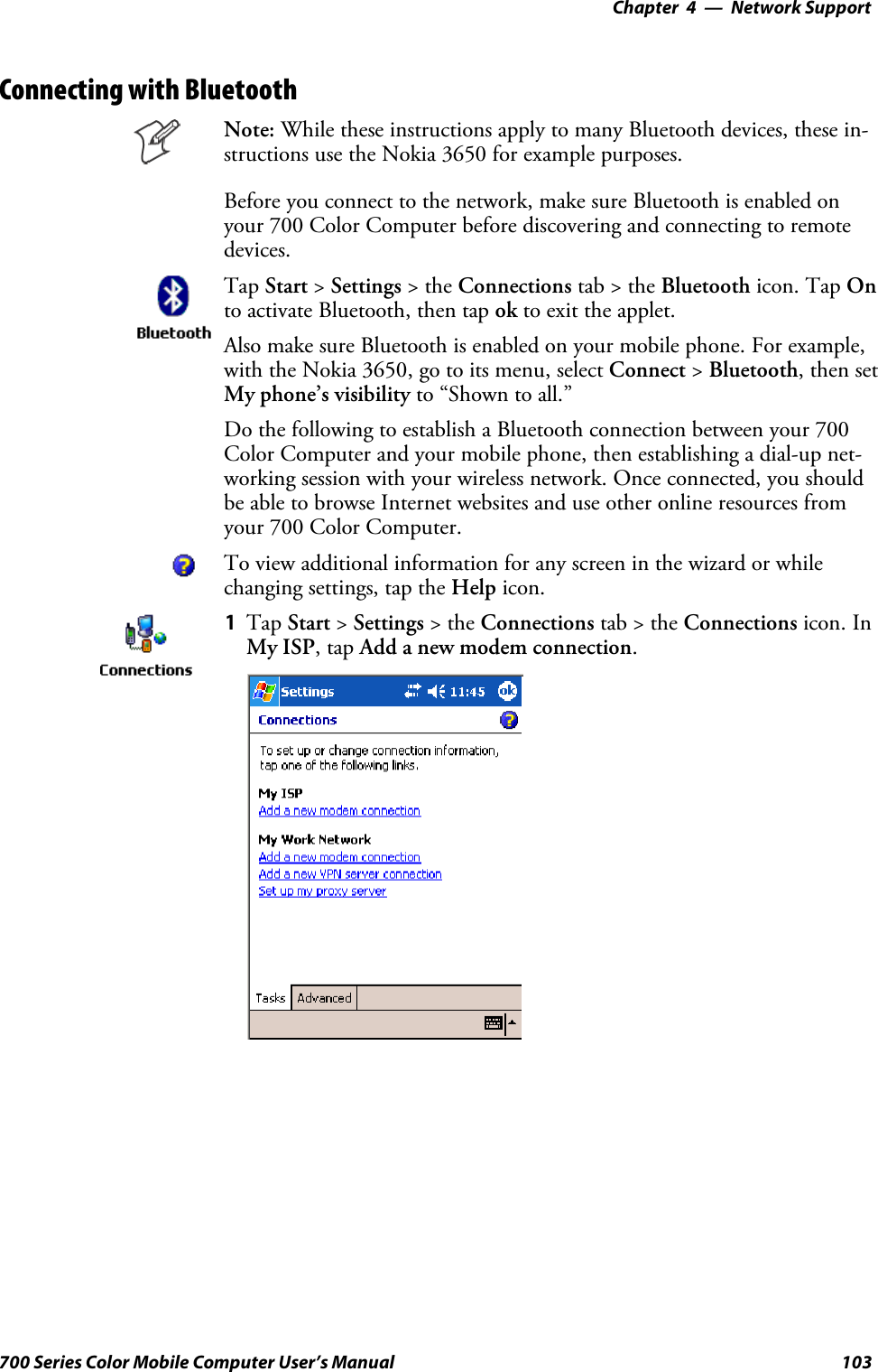

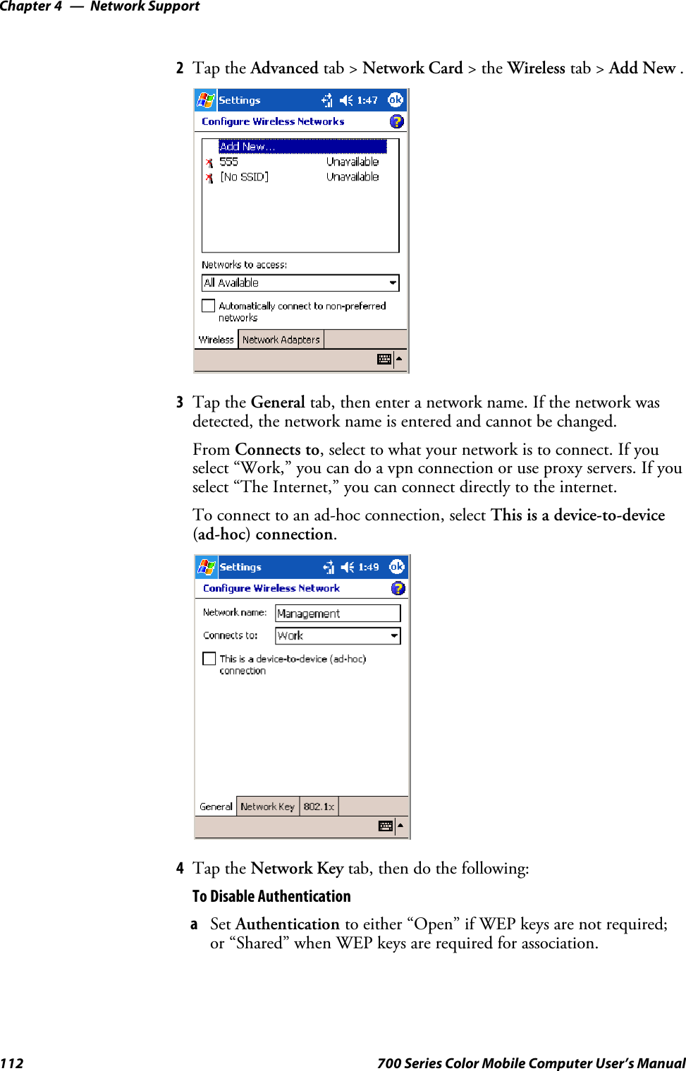
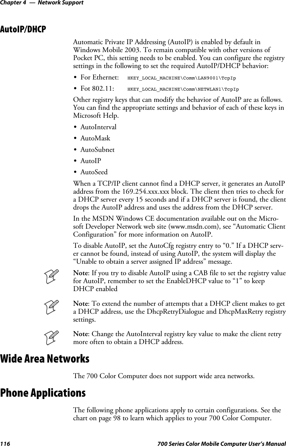
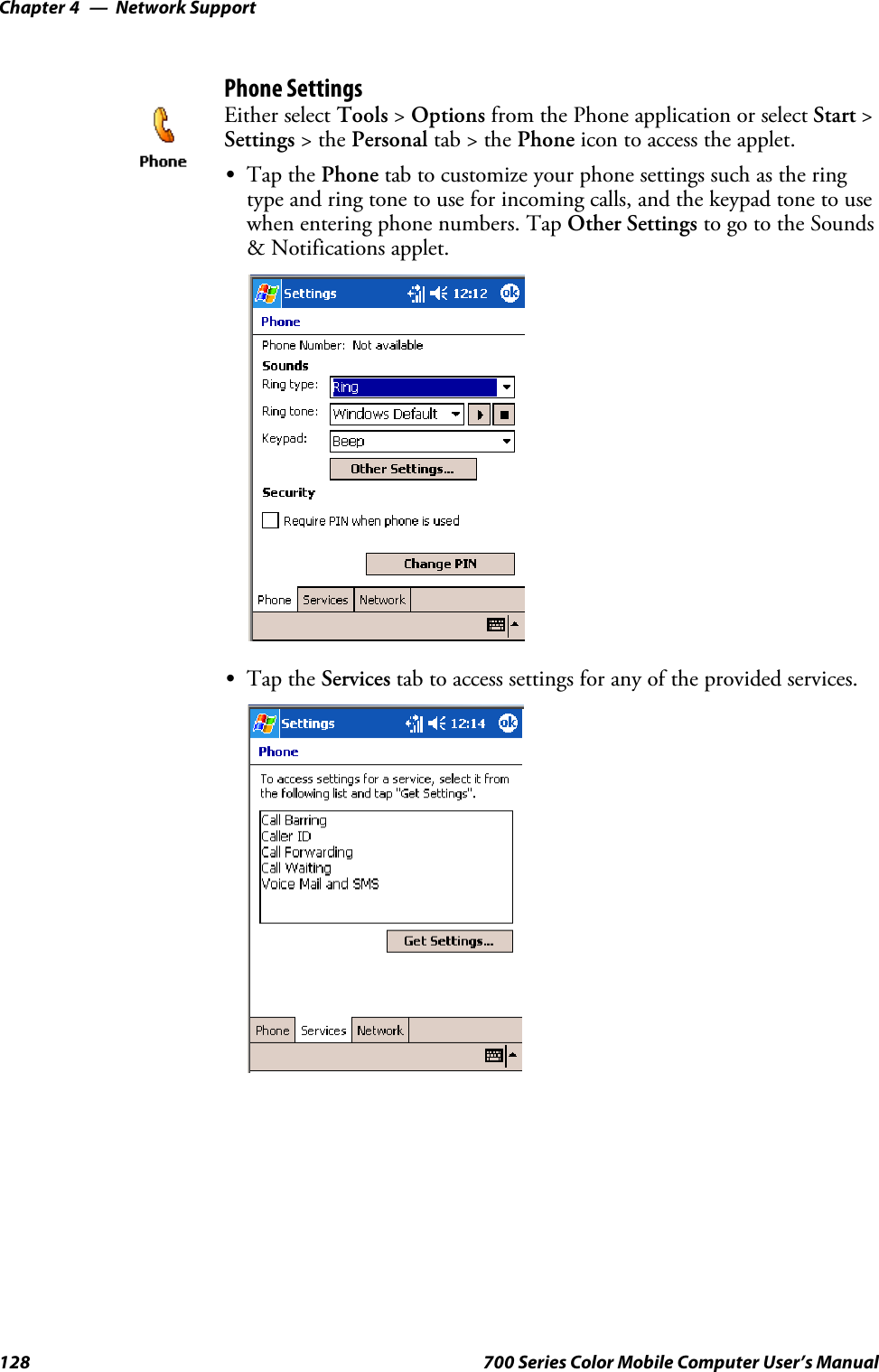
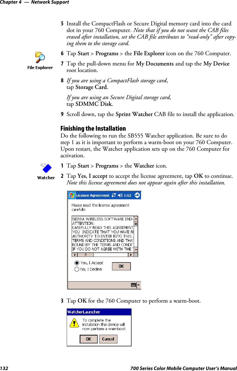
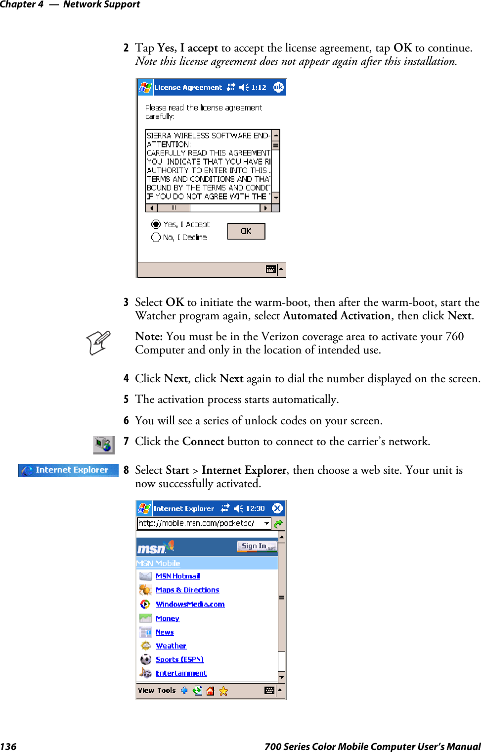
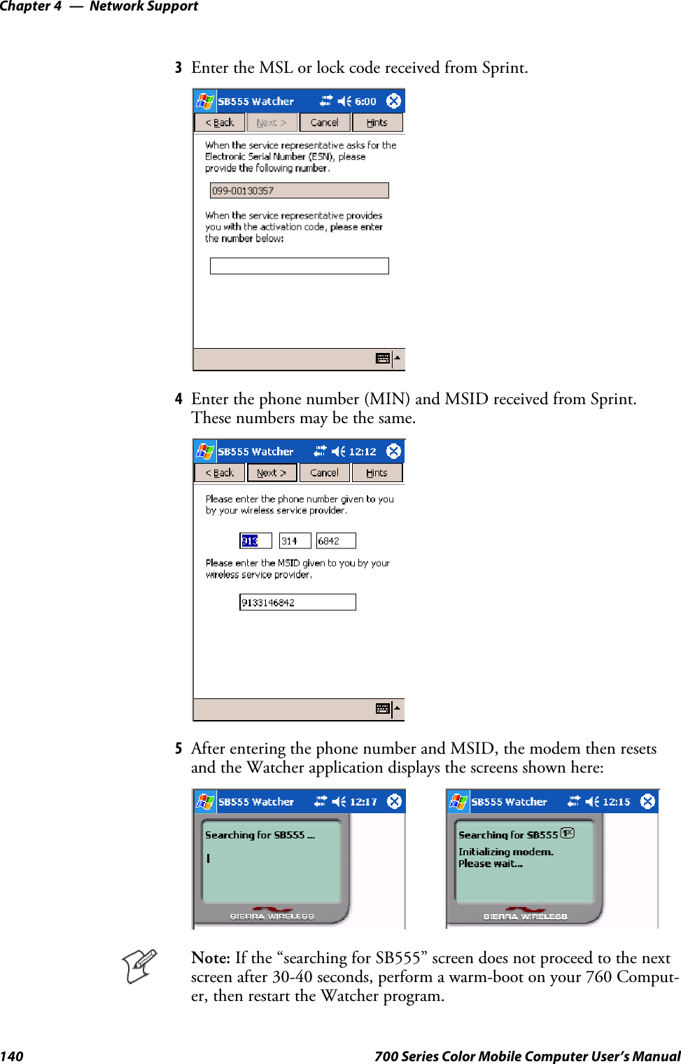
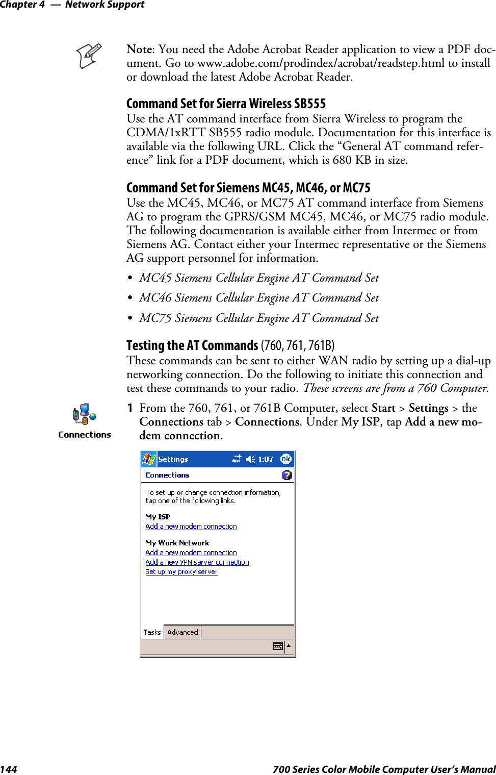
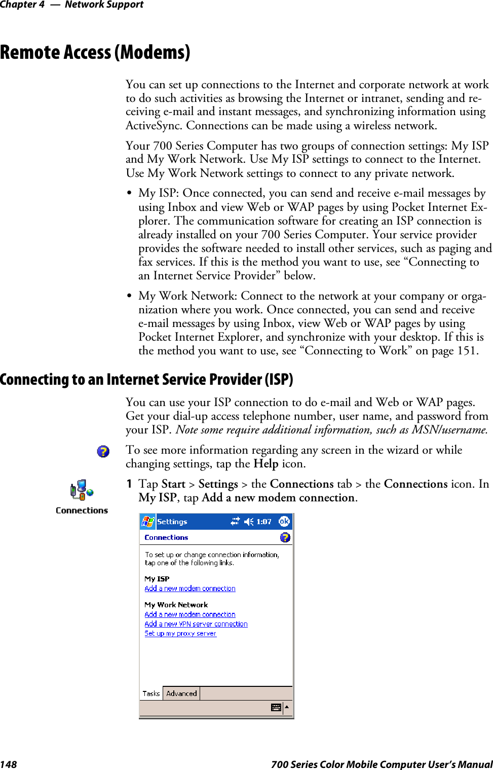
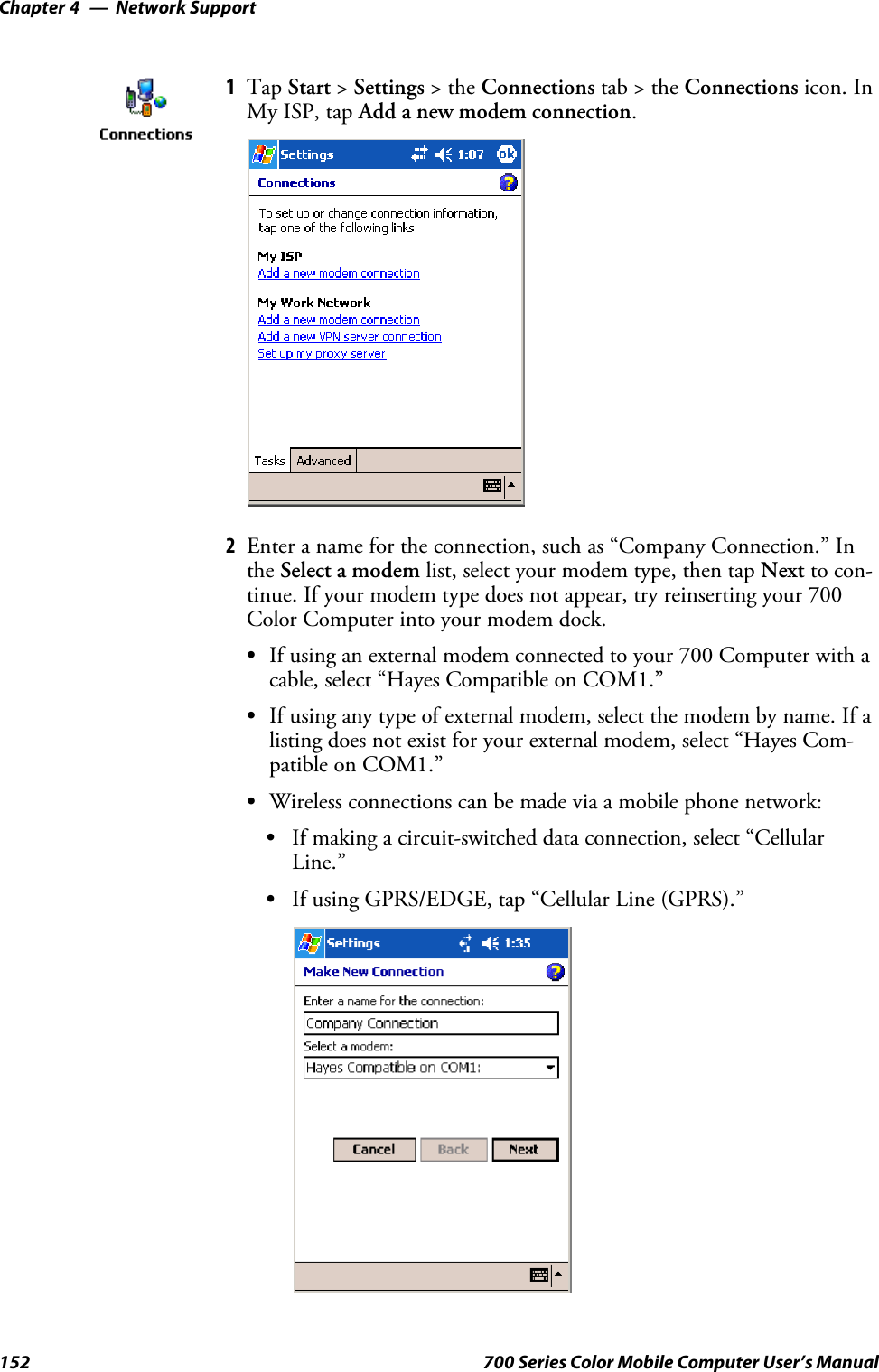

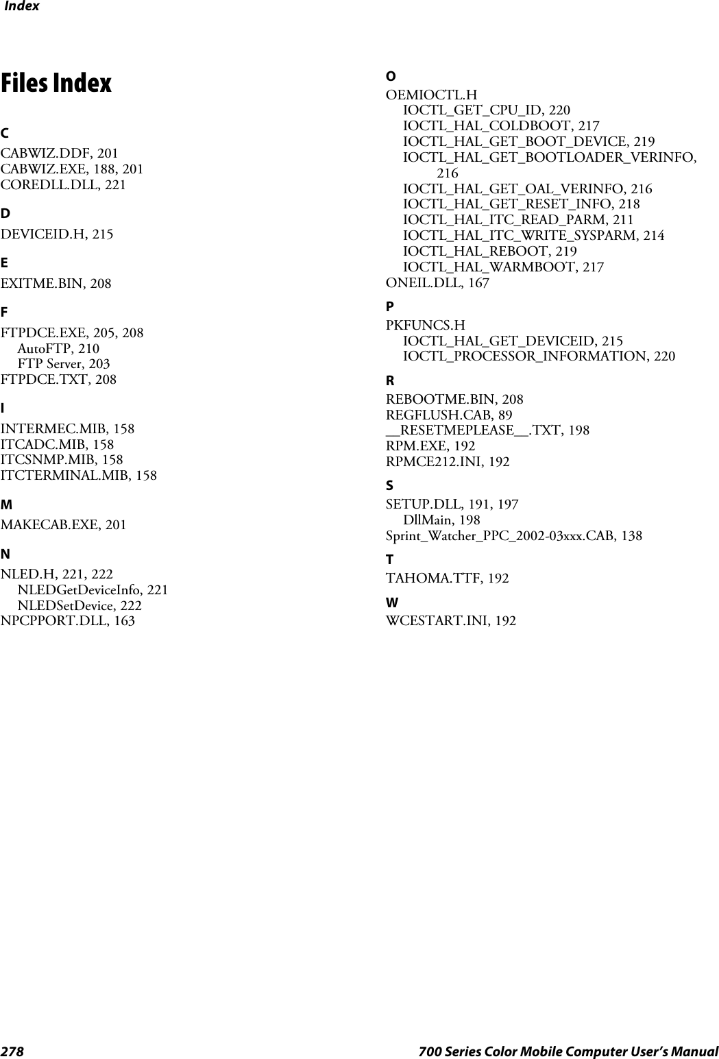
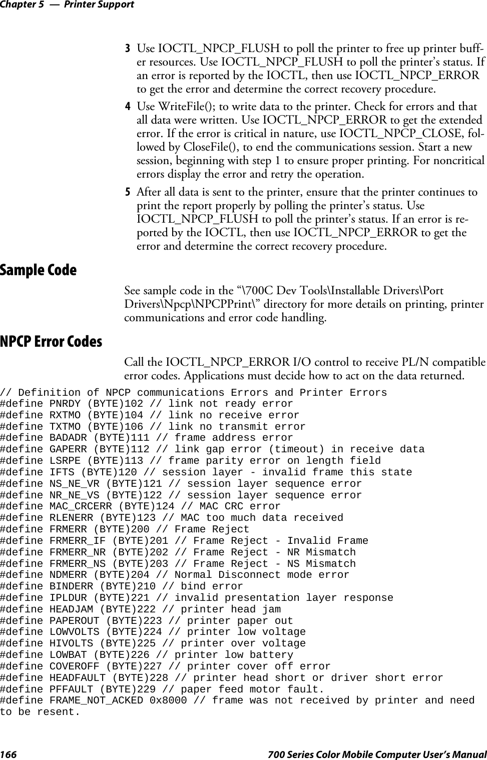
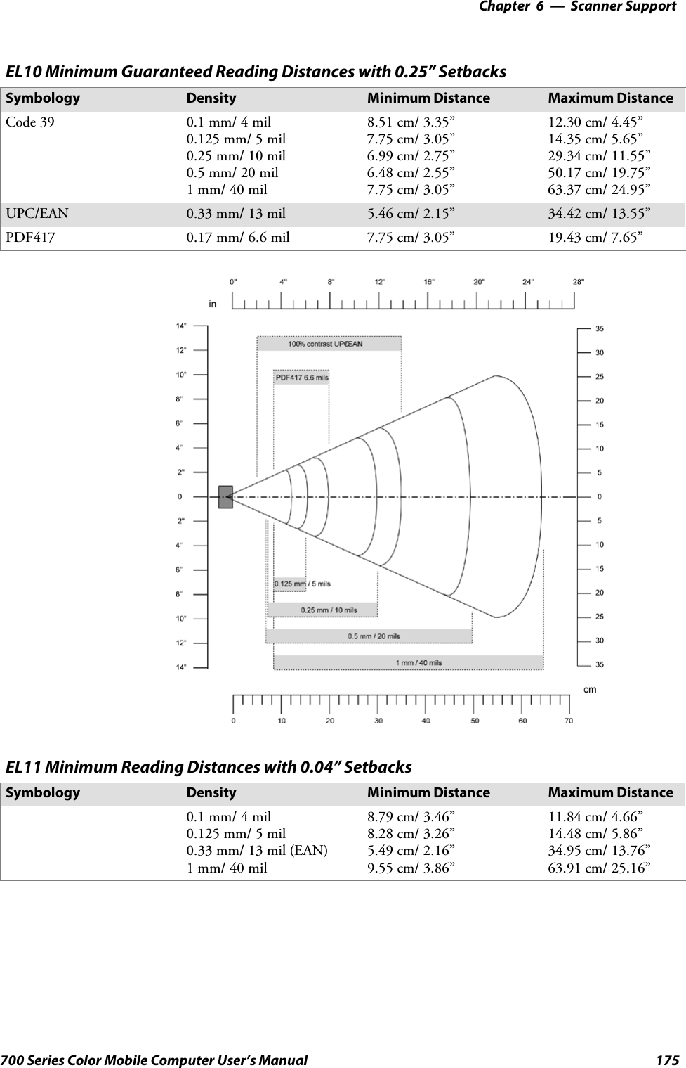
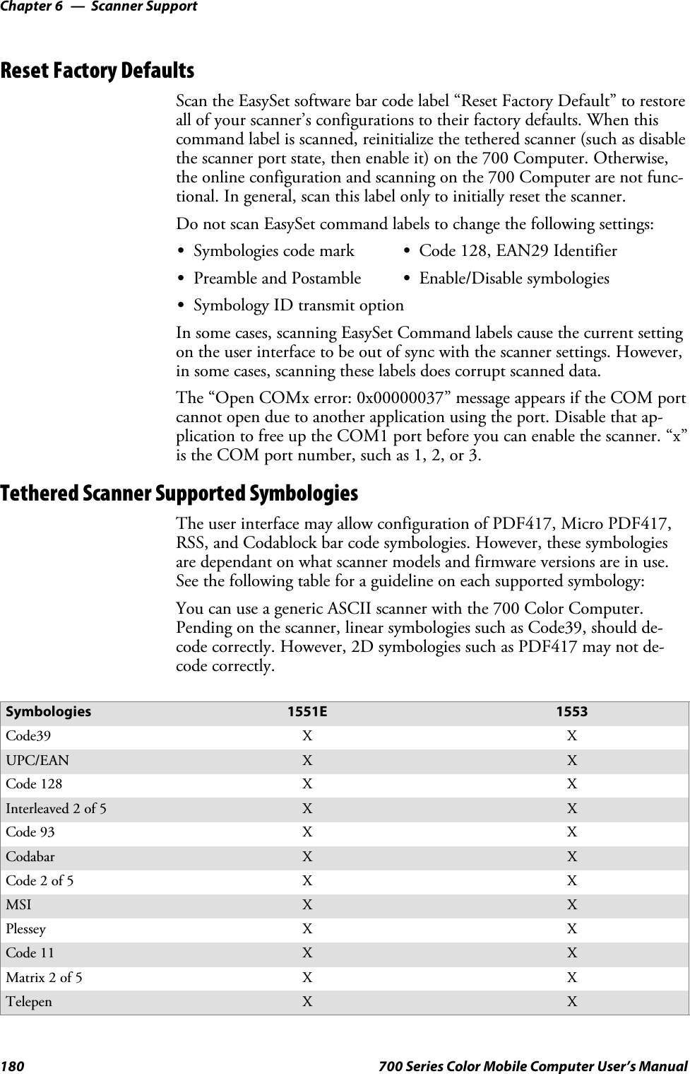
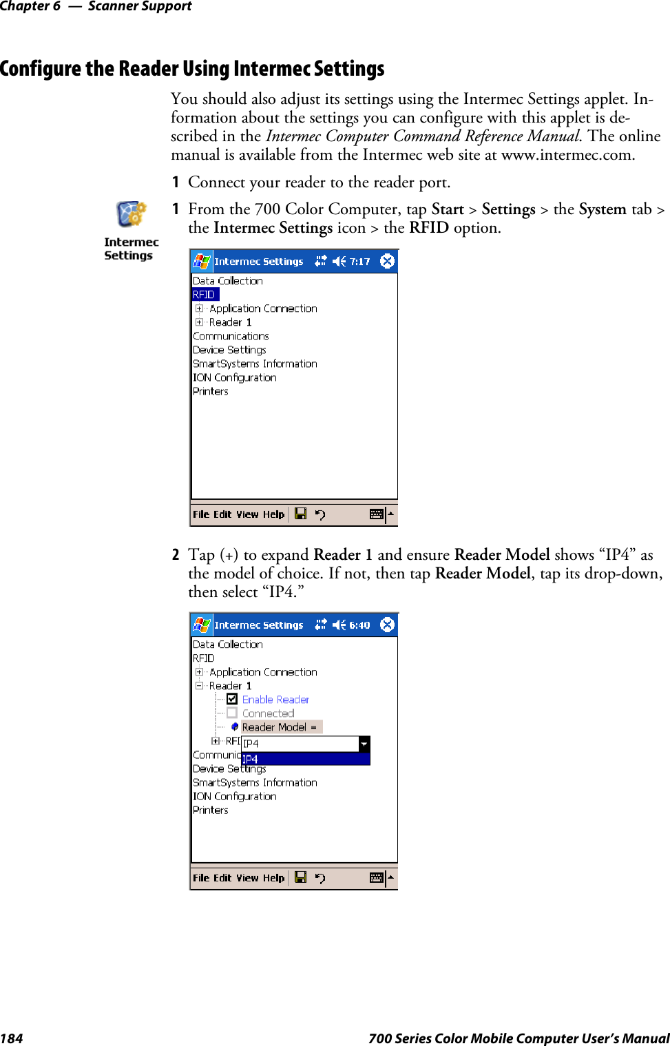
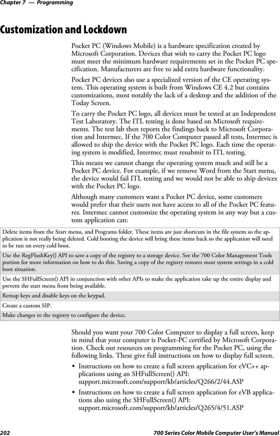
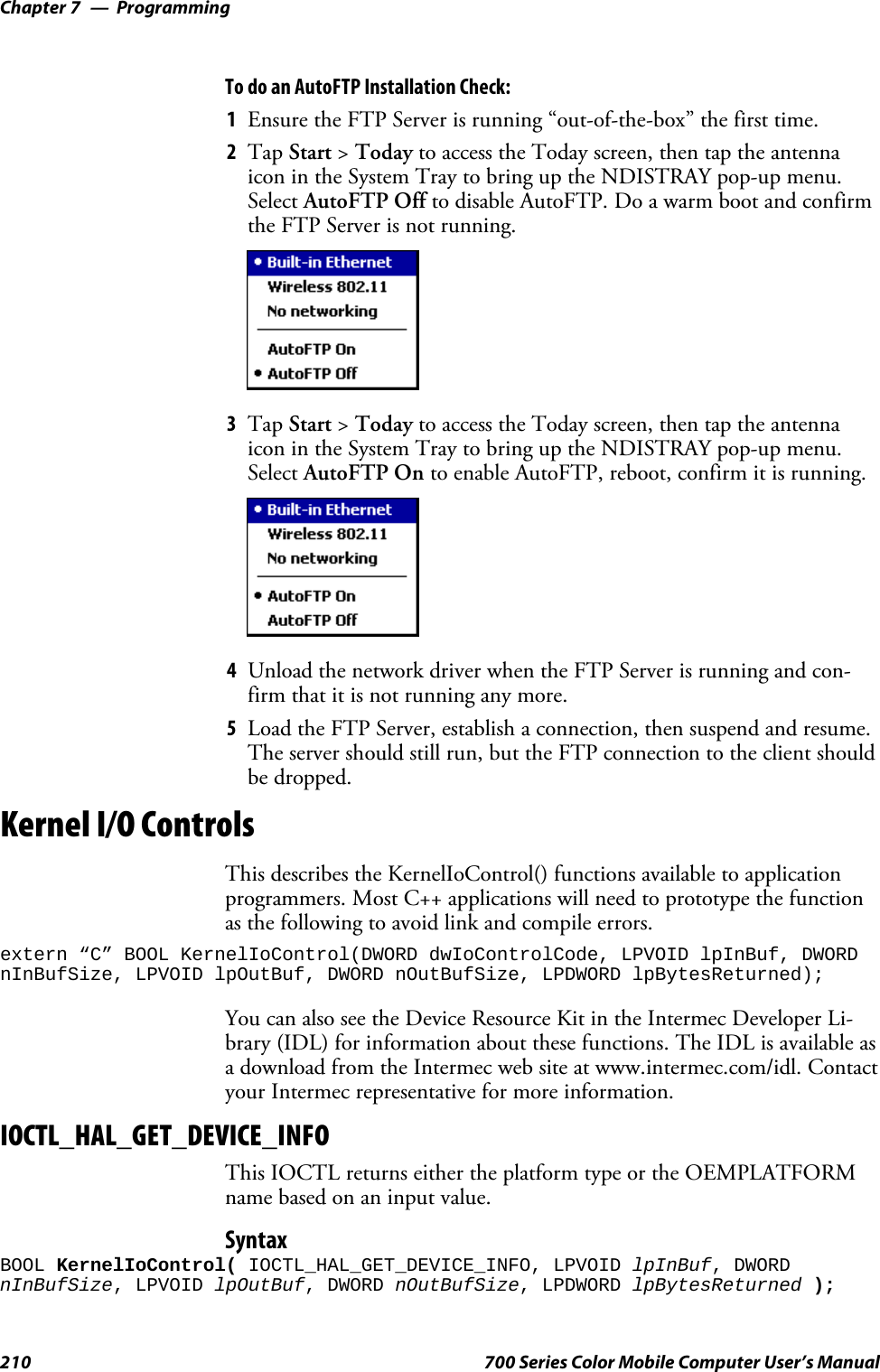
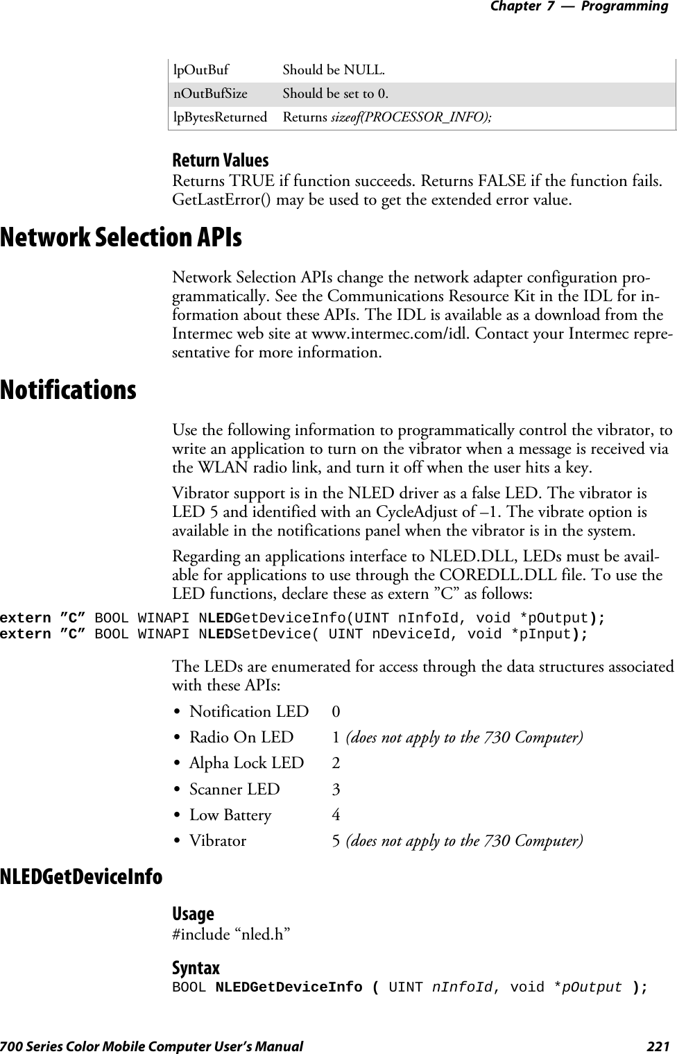
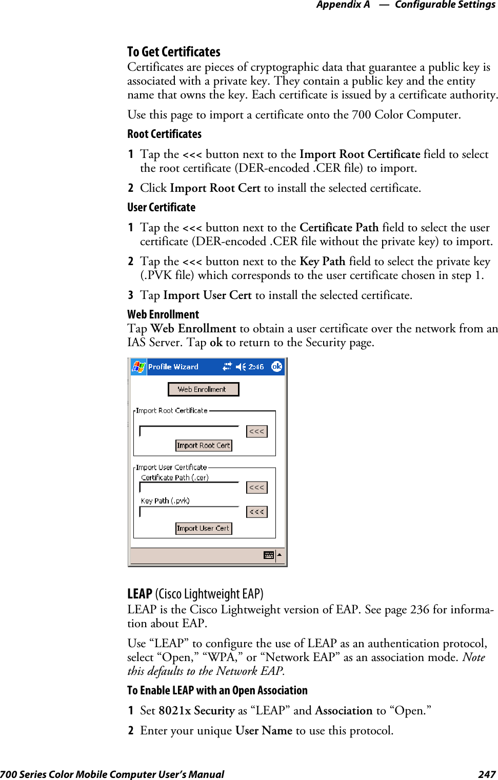
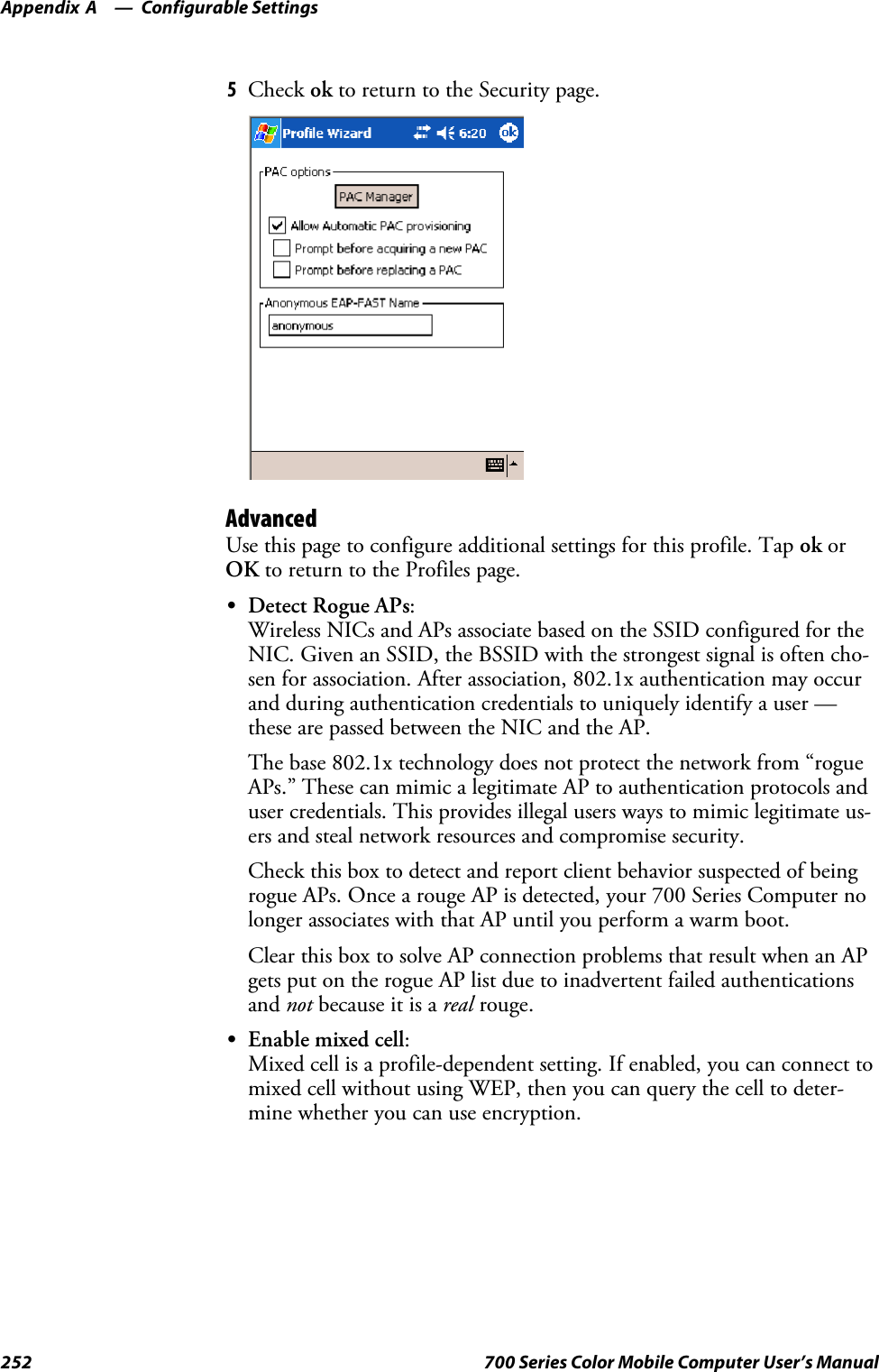
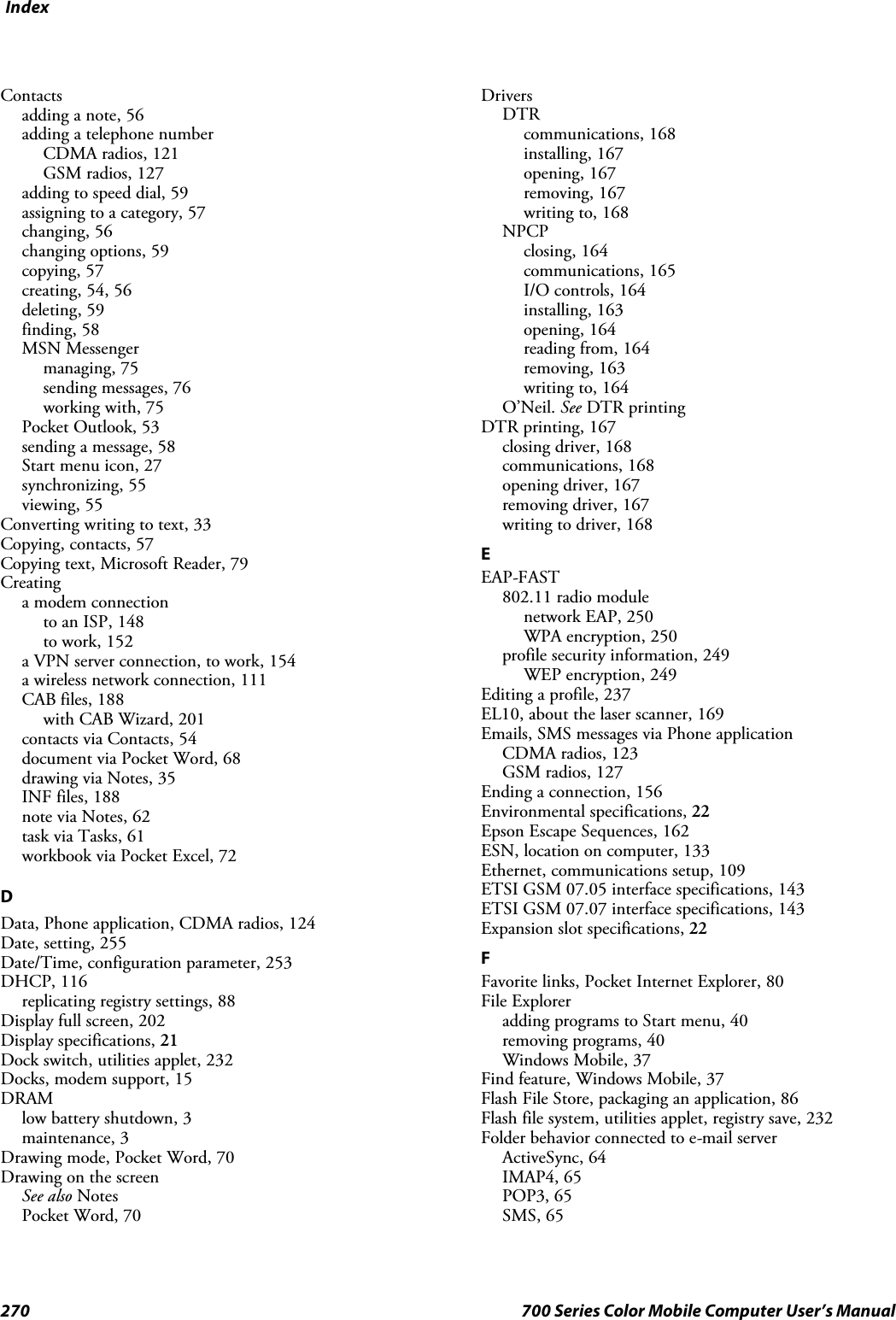
![Printer Support—Chapter 5163700 Series Color Mobile Computer User’s ManualNPCP Printer DriverThe NPCP printer communications driver (NPCPPORT.DLL) is aStream Device Driver built into the operating system. The driver supportsonly NPCP communications to and from the 6820 and 4820 printers overa selected serial port.All applications use WIN32 API functions to access drivers. Applicationseasily implement basic operations through the CreateFile(), WriteFile(),ReadFile(), DeviceIOControl(), and CloseHandle() Win32 APIs.DeviceIOControl() functions are used to do most upgrade printer mod-ules, printer diagnostics, and get printer configurations.About NPCPNPCP (Norand®Portable Communications Protocol) is a proprietaryprotocol that provides session, network, and datalink services for Intermecmobile computers in the Intermec LAN environment used with printersand data communications.NPCP Driver Installation and RemovalUse LPT9: for the NPCP printer device and COM1 for the last parame-ter. COM1 is the connection available via the 700 Color Computer.Applications use the RegisterDevice() function to install the driver.DeregisterDevice() uninstalls the device driver and frees memory spacewhen the driver is not required. Use the HANDLE returned byRegisterDevice() as the parameter to DeregisterDevice().Use the RegisterDevice() function call as demonstrated below. Specify thefull path name to the driver starting at the root for the RegisterDevice()function to work properly. The last parameter to RegisterDevice() is aDWORD that represents the name of the port for the NPCP streamdriver to use. Build this parameter on the stack if it is not to be paged outduring the call. The first parameter “LPT” (Device Name) and the secondparameter “9’ (index), indicate the name of the registered device, such asLPT9. This is used in the CreateFile() function call.Install(){HANDLE hDevice;TCHAR port[6];port[0] = TCHAR(‘C’);port[1] = TCHAR(‘O’);port[2] = TCHAR(‘M’);port[3] = TCHAR(‘1’);port[4] = TCHAR(‘:’);port[5] = TCHAR(0);hDevice = RegisterDevice ( (TEXT(”LPT”), 9,TEXT(“\\STORAGE CARD\\WINDOWS\\NPCPPORT.dll”), (DWORD)port);}](https://usermanual.wiki/Intermec-Technologies/MC75.Final-Users-Manual-part-2-of-2/User-Guide-730133-Page-63.png)
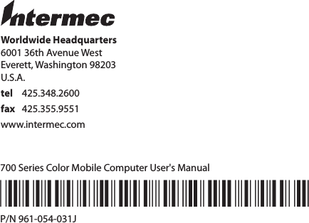
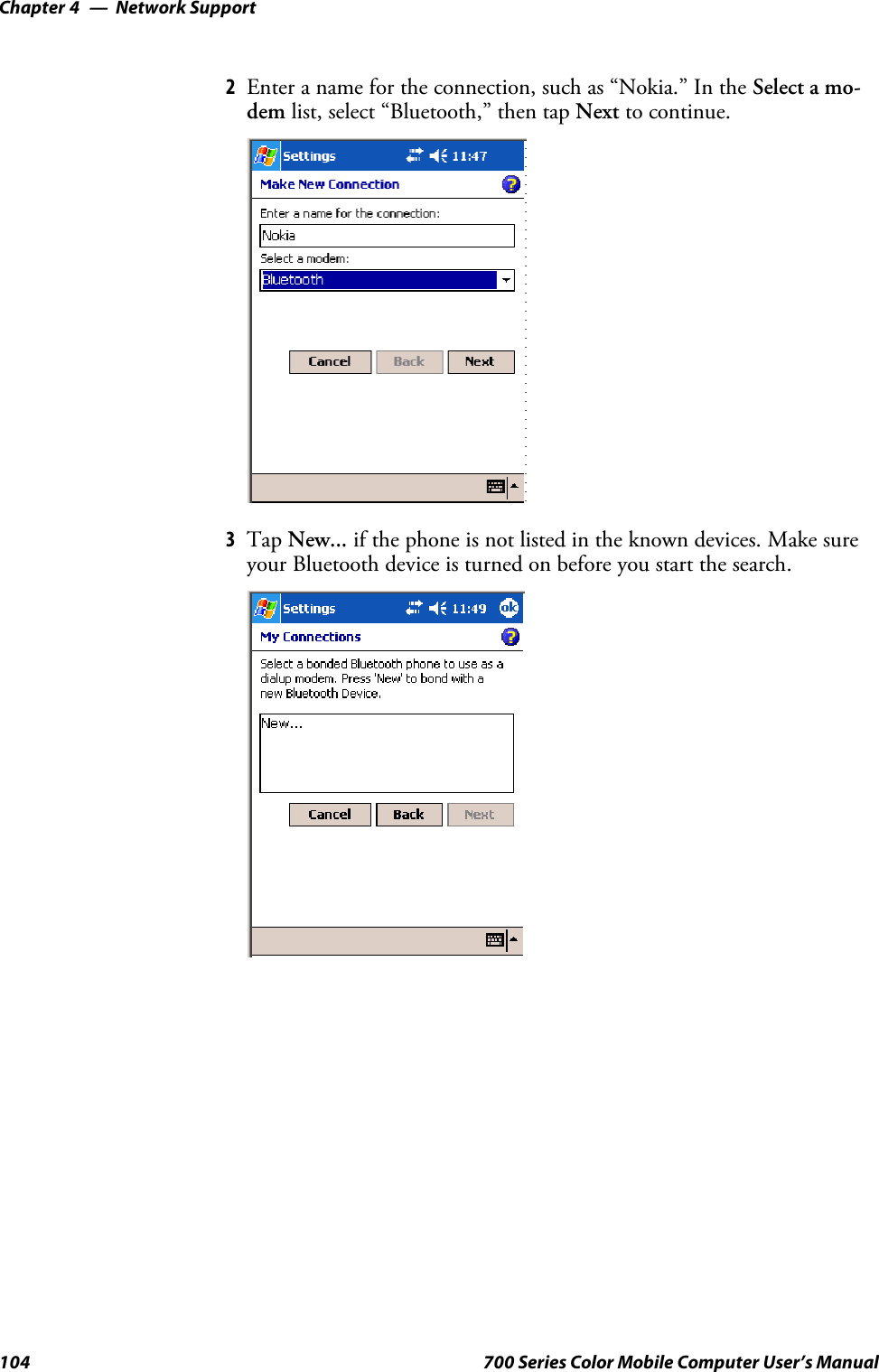
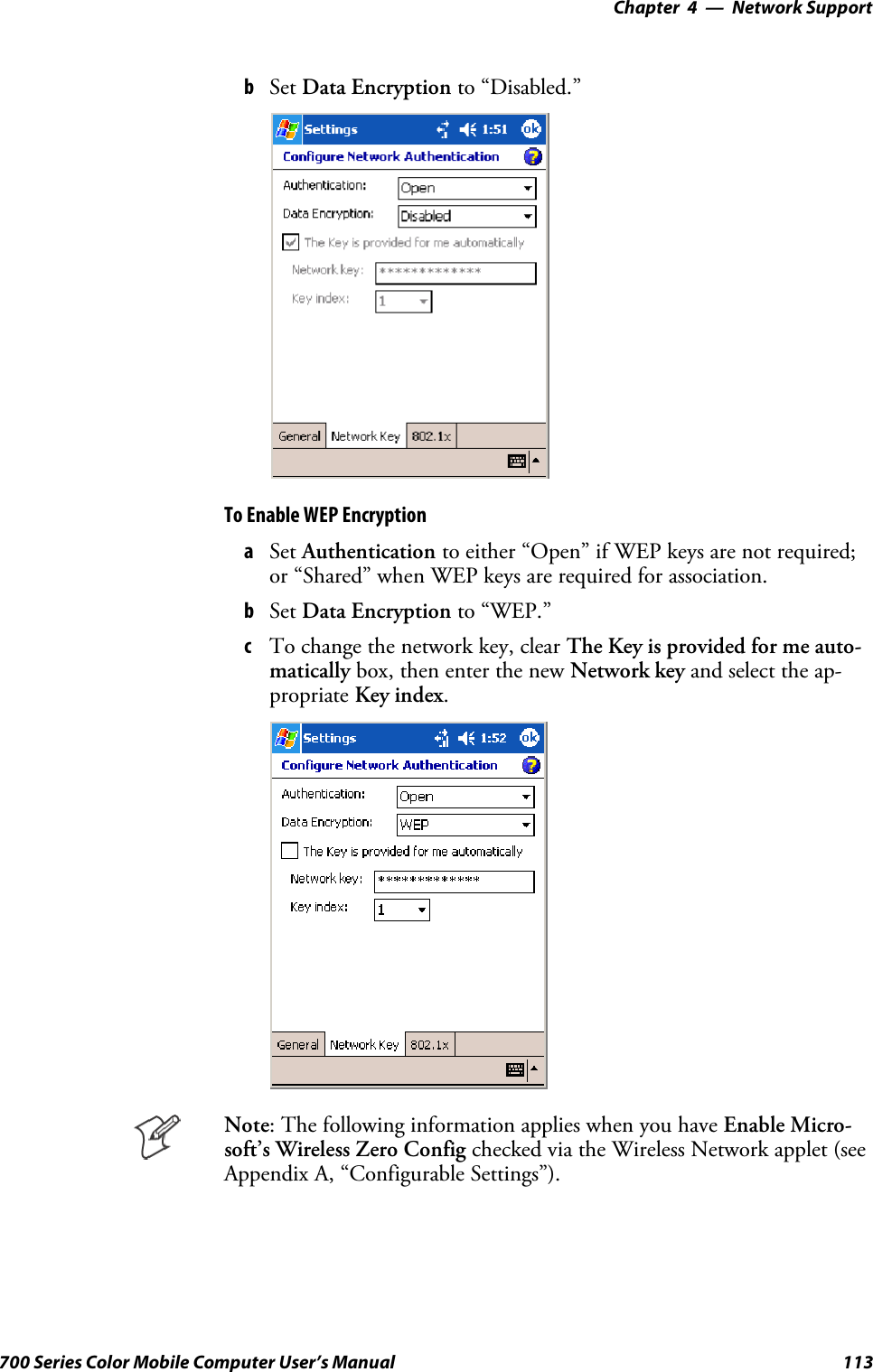
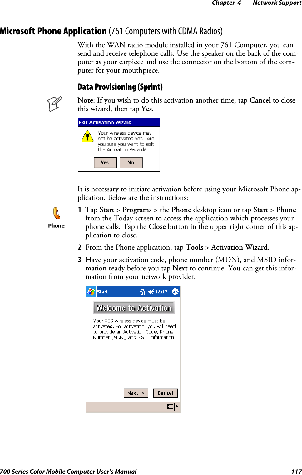
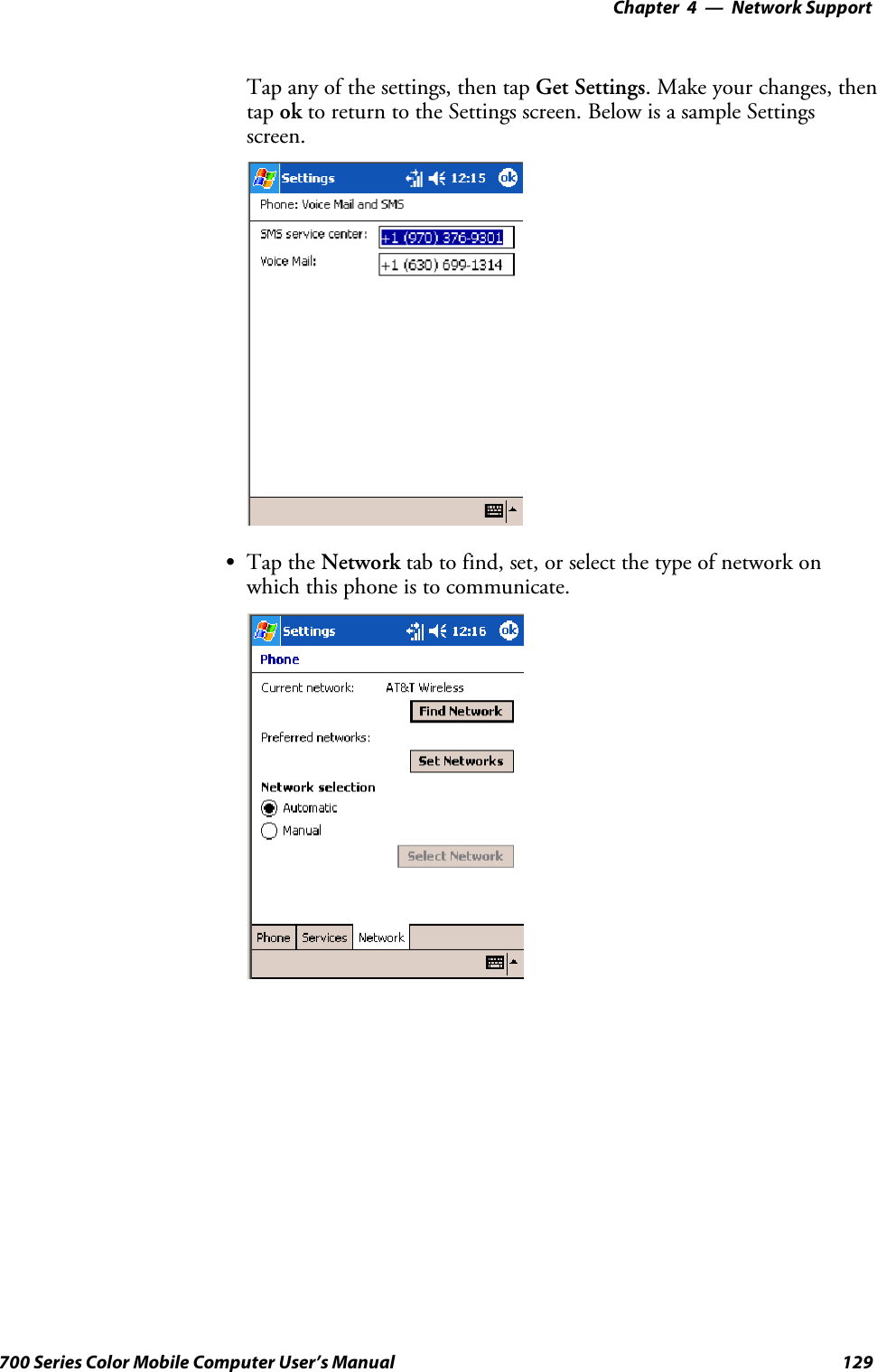
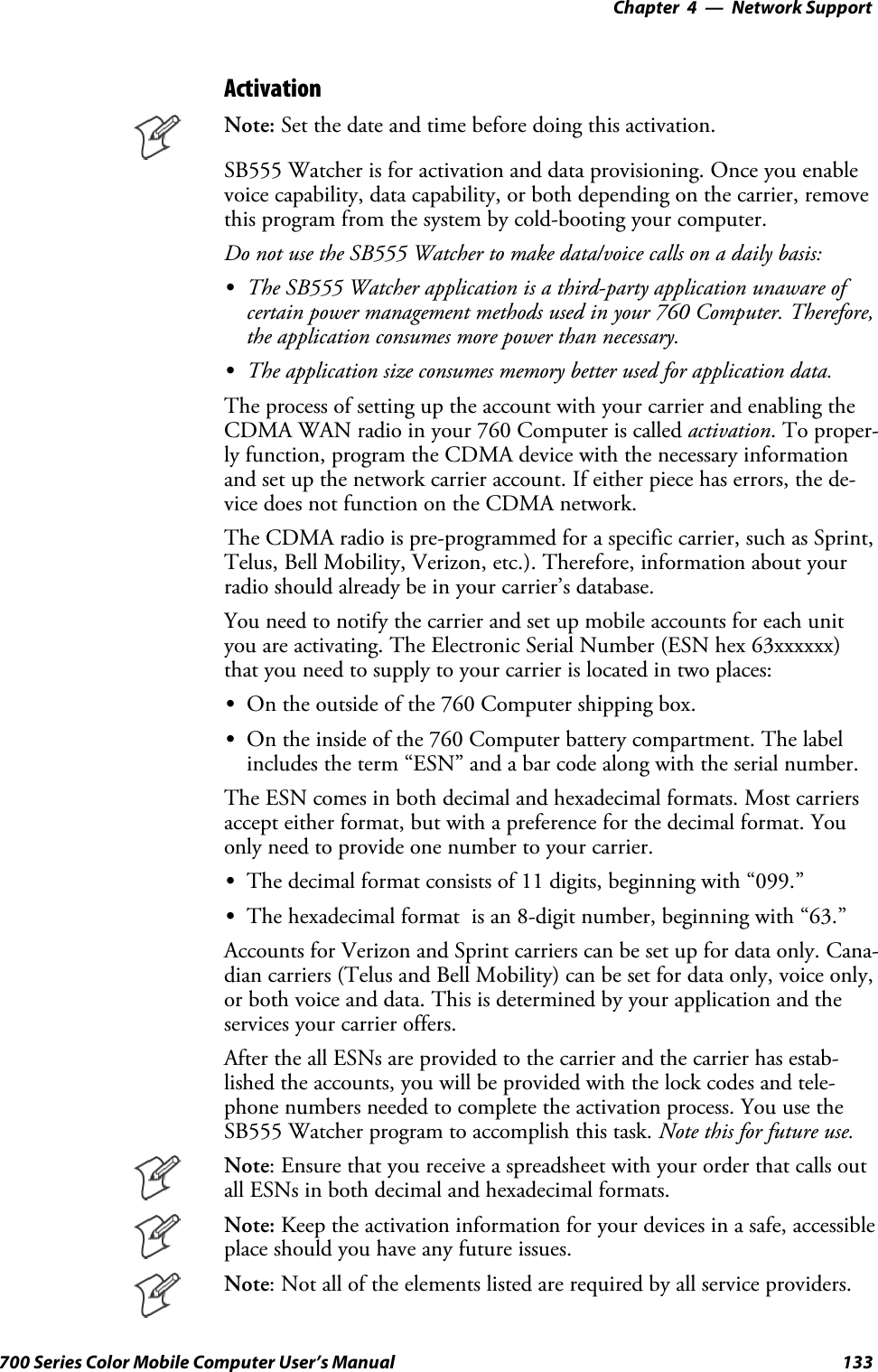
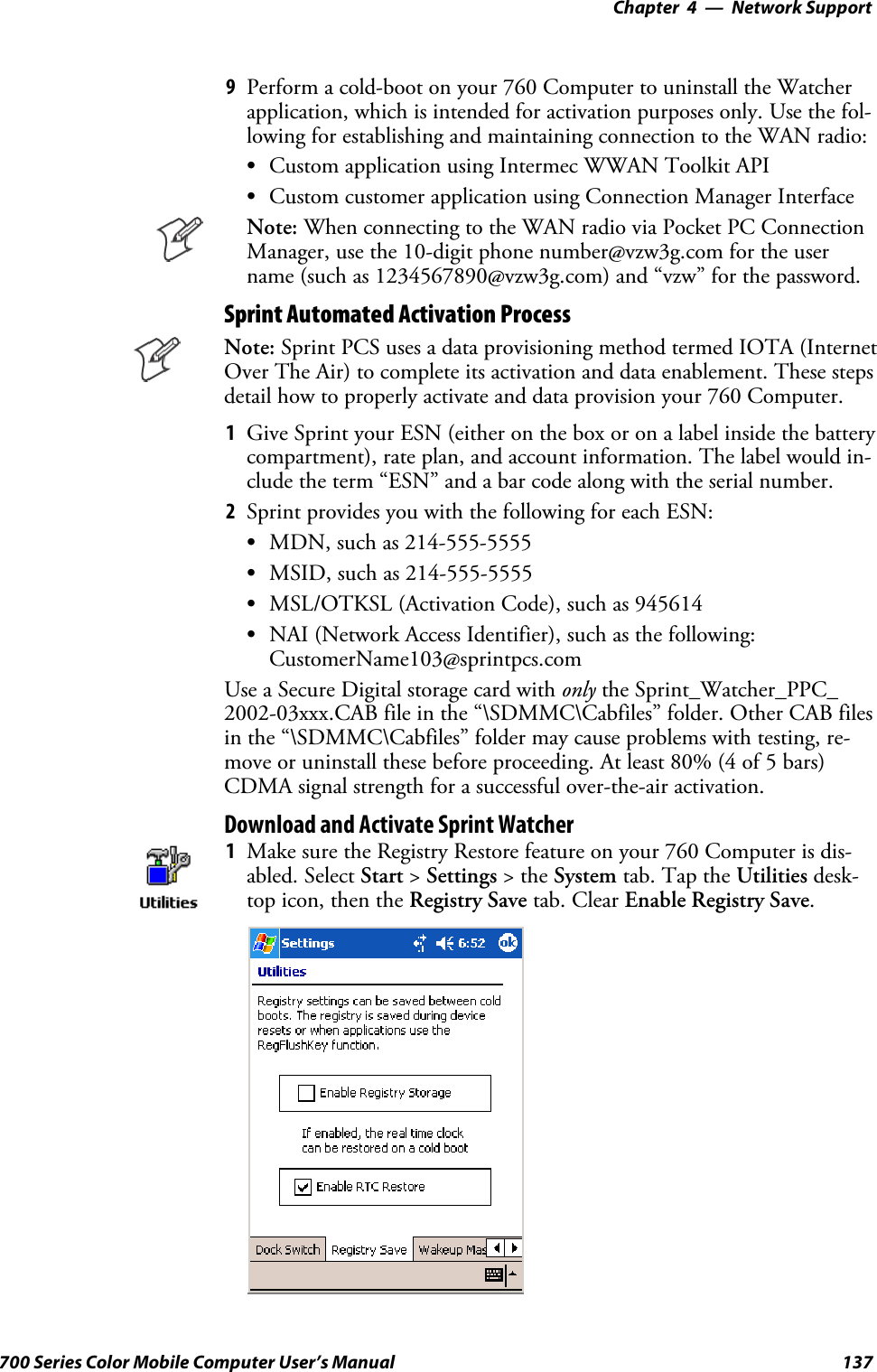
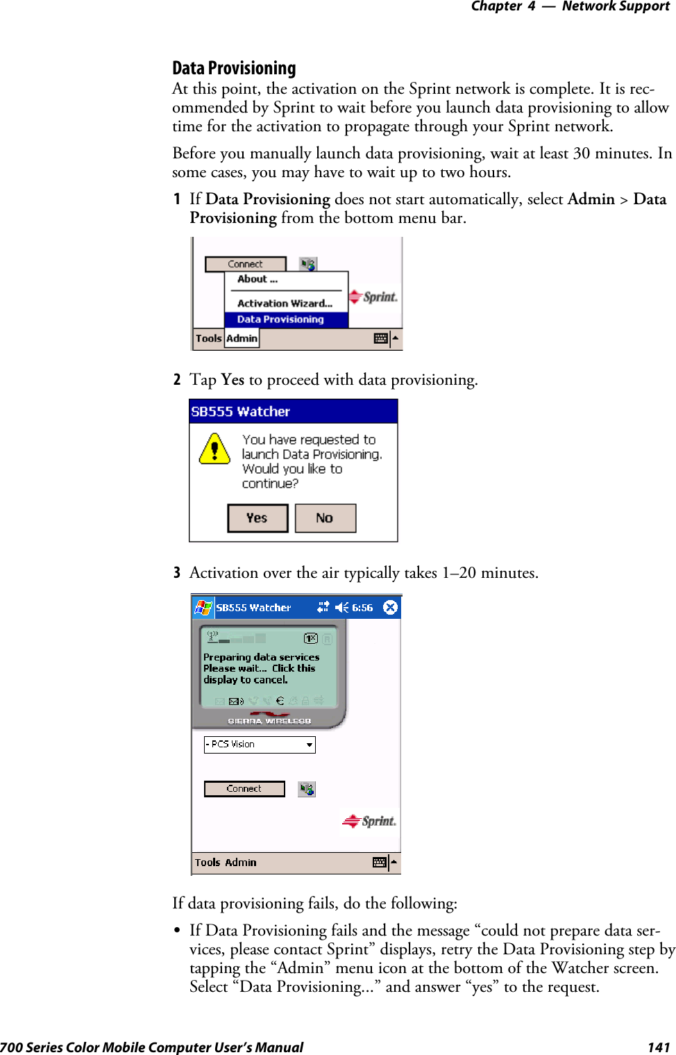
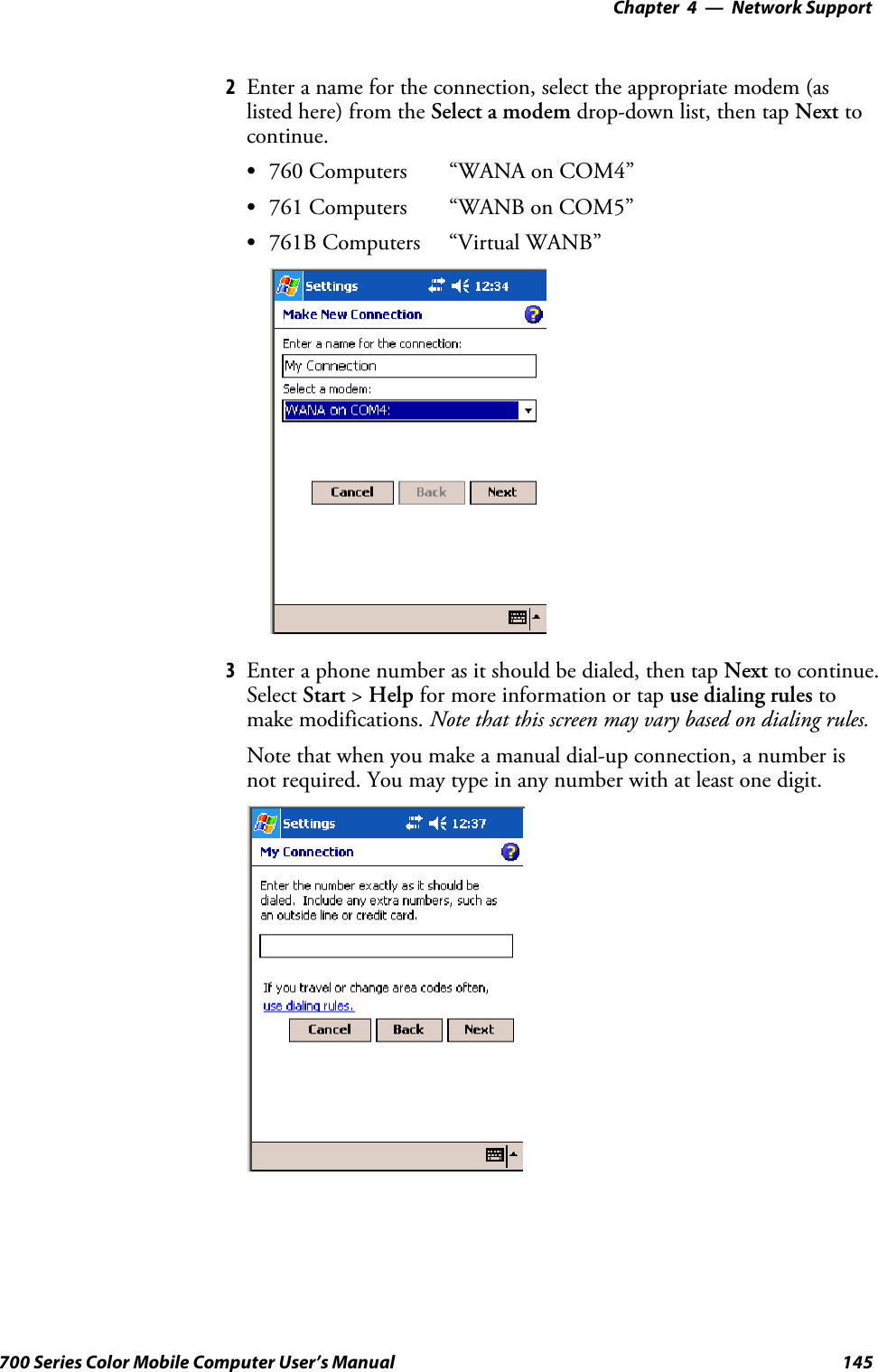
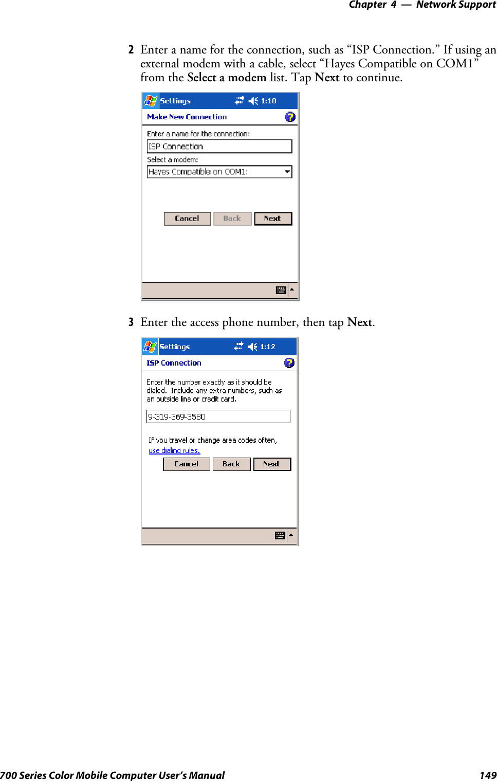
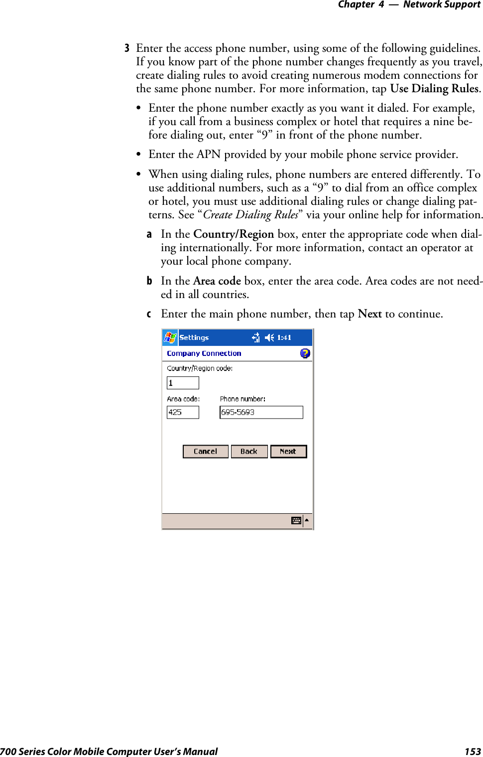
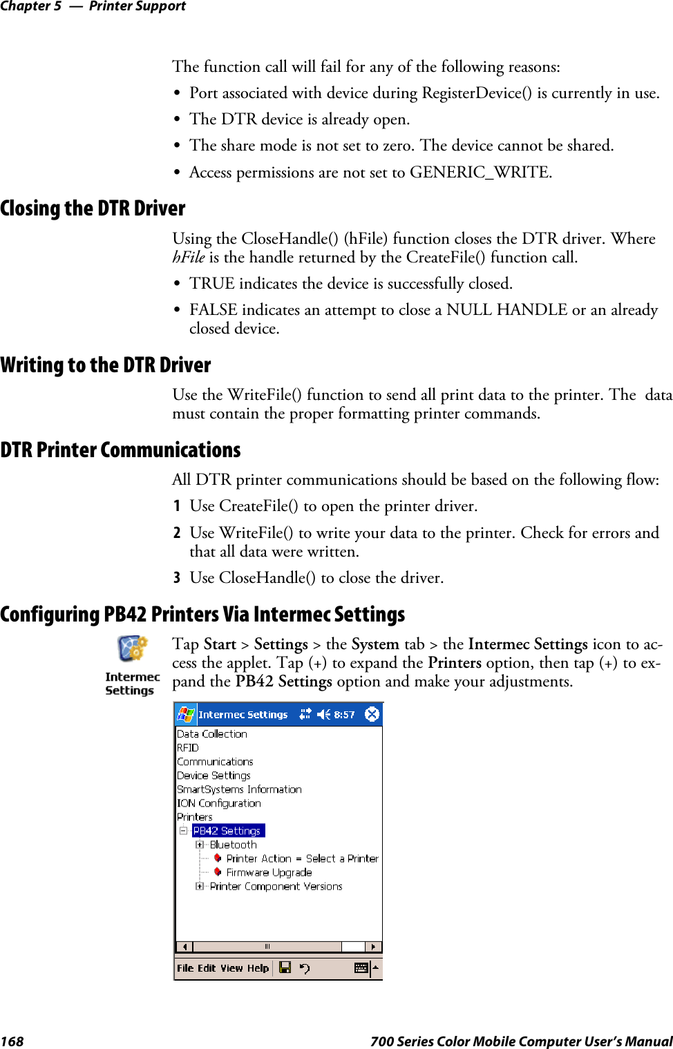
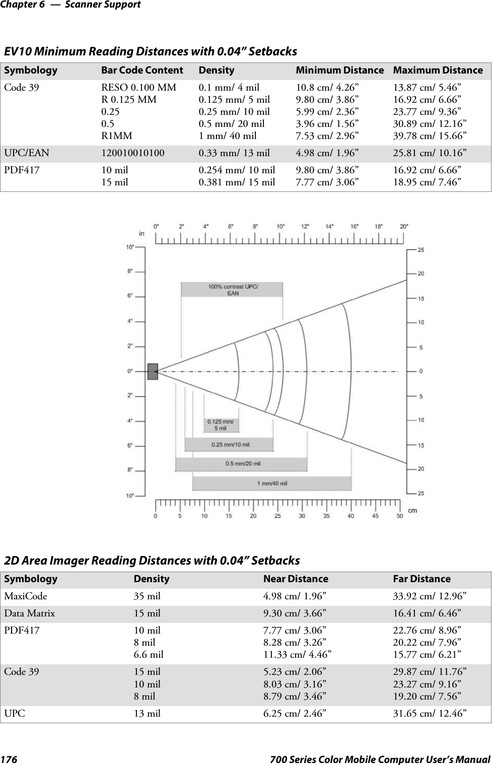
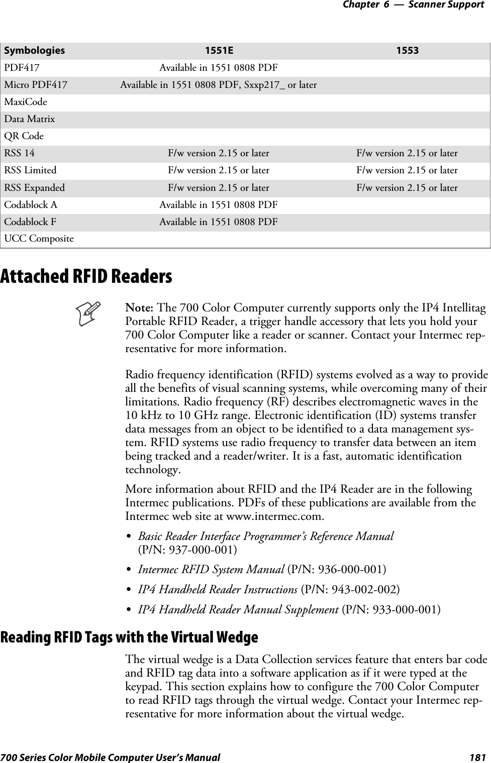
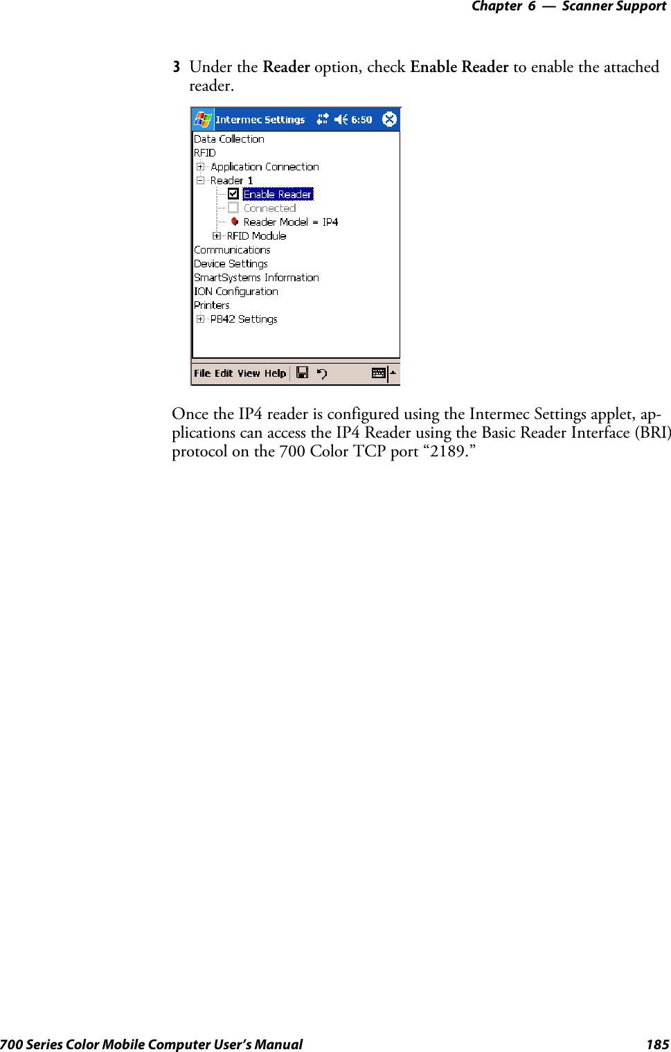
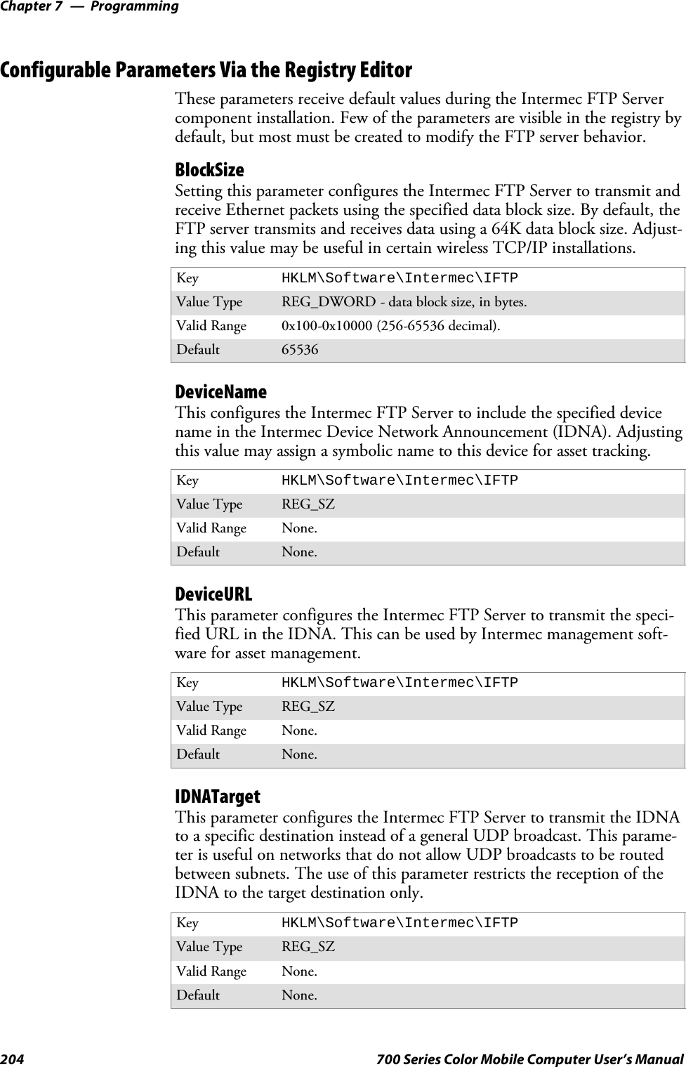
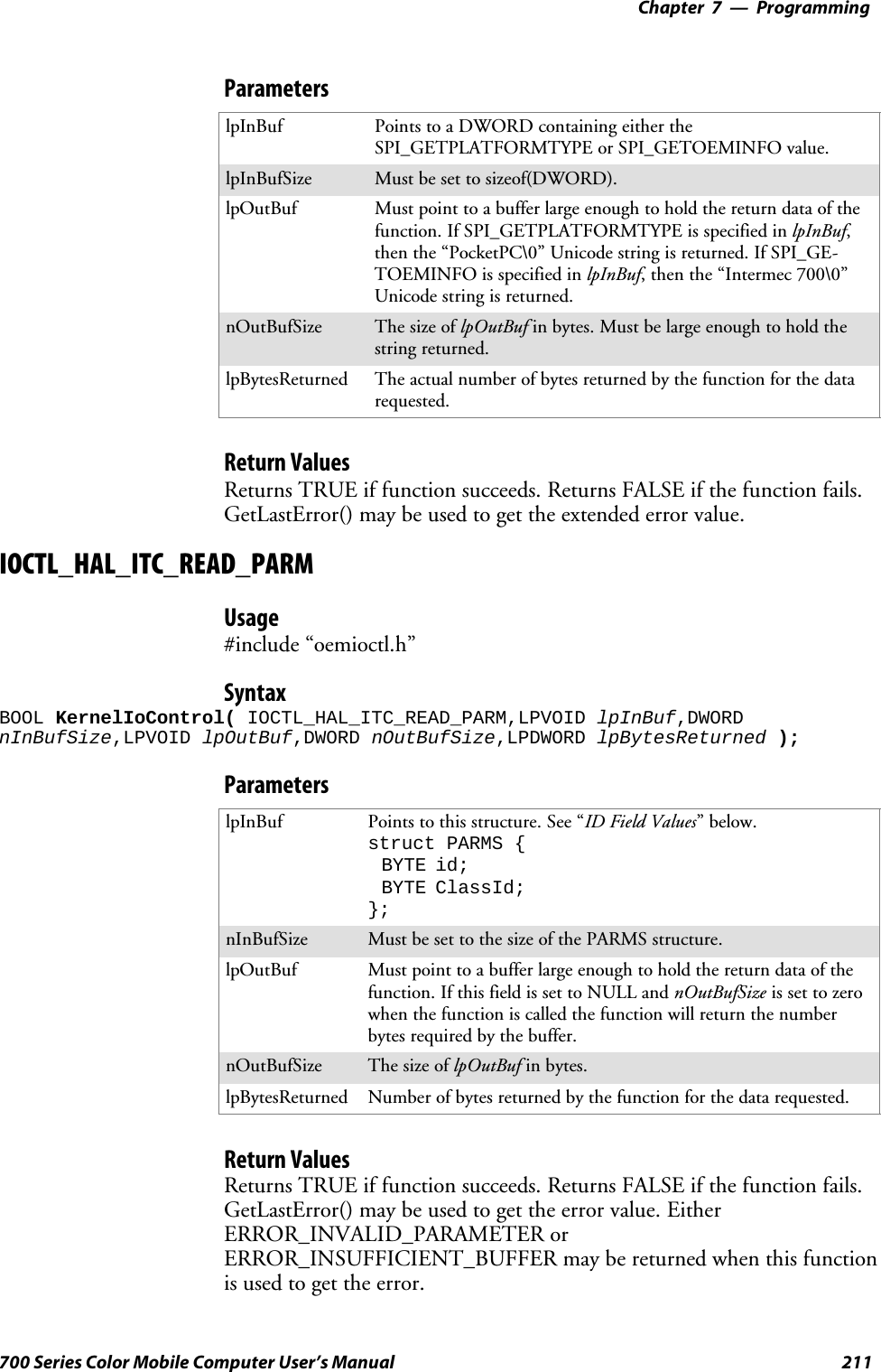
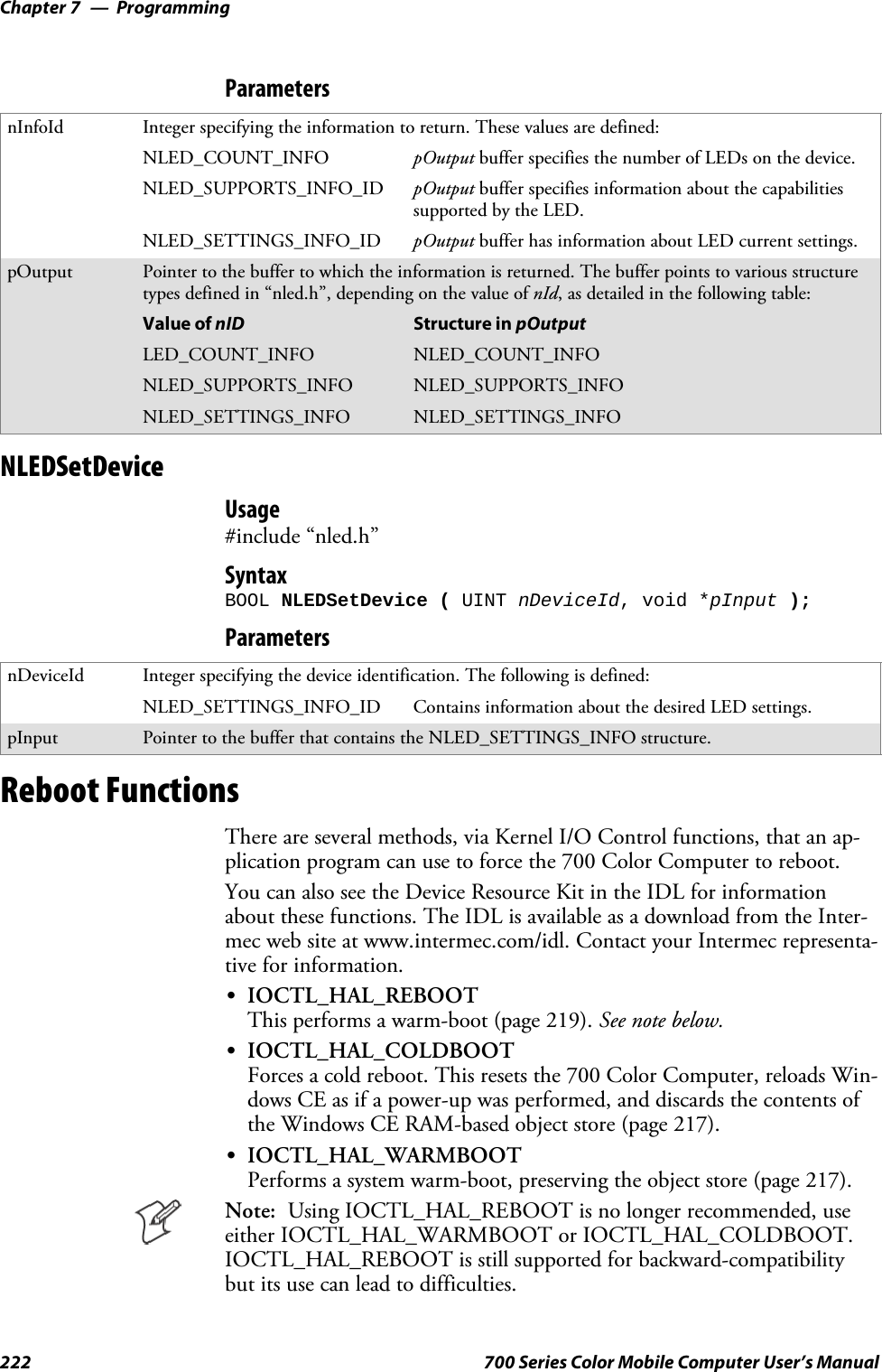
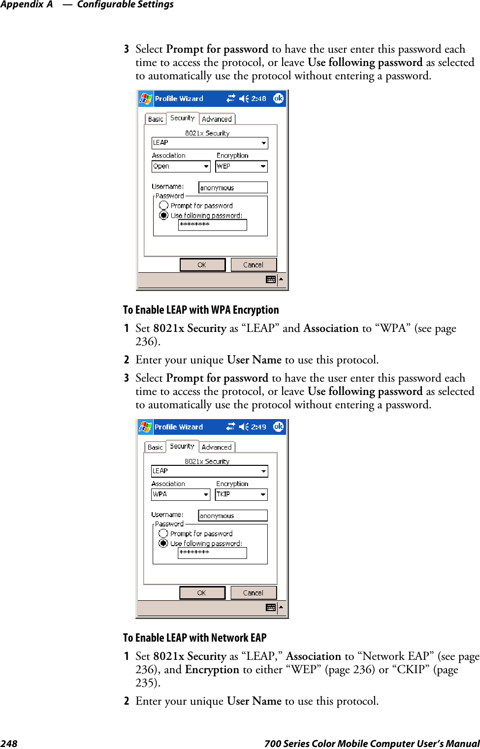
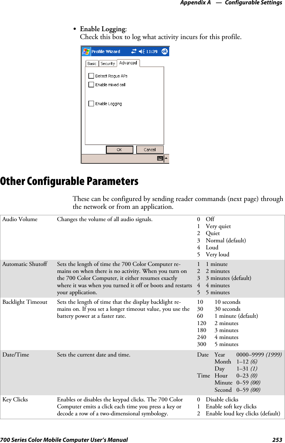
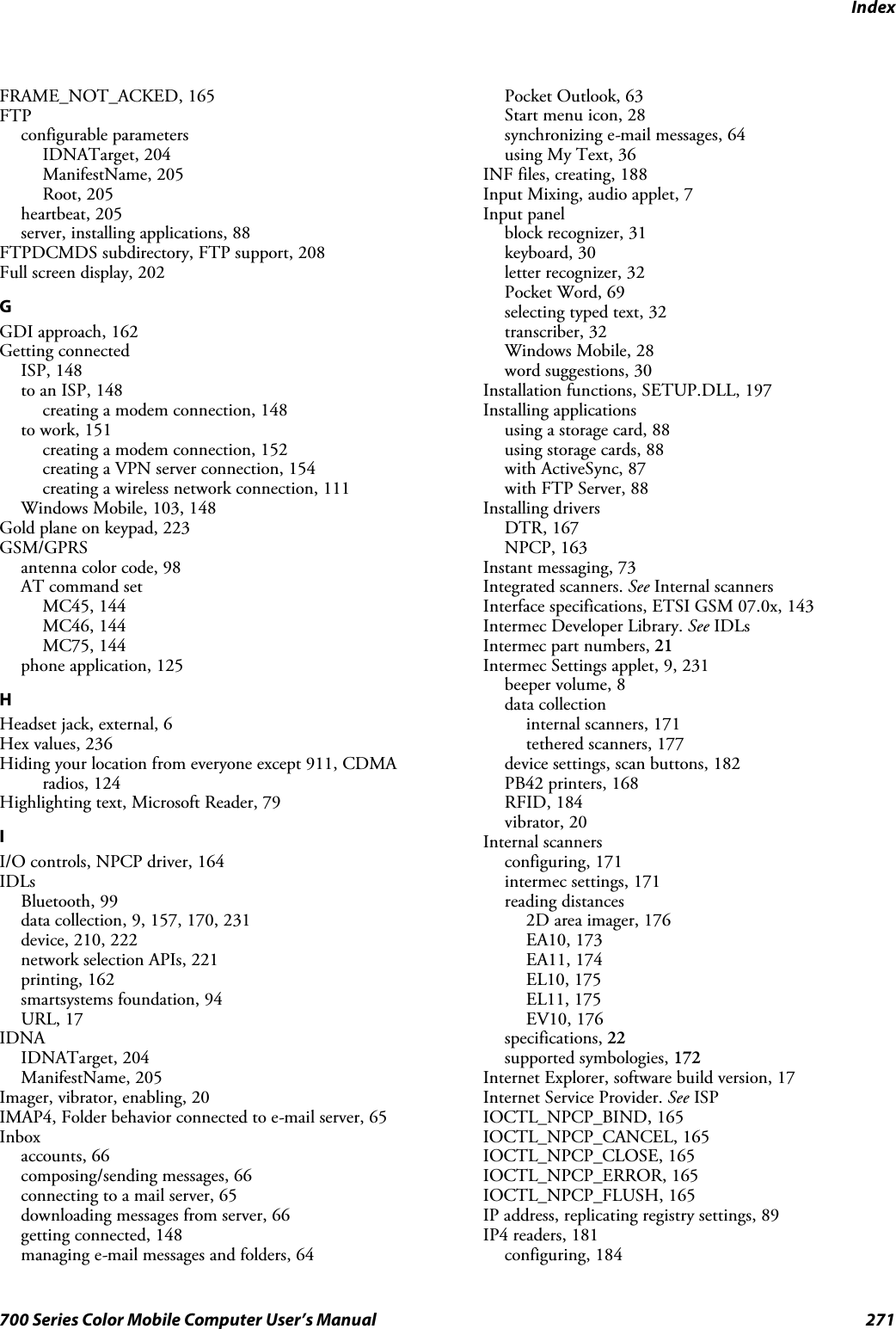
![Printer Support—Chapter 5167700 Series Color Mobile Computer User’s ManualO’Neil Printer DriverThe DTR printer communications driver is a Stream Device Drivernamed ONEIL.DLL.All applications use WIN32 API functions to access drivers. Applicationseasily implement basic operations using the CreateFile(), WriteFile(),DeviceIOControl() and CloseHandle() Win32 APIs.The driver supports communications to 6804DM, 6804T, 6805A, 6806,6808, 681T, PB20, and PB42 printers over a selected serial port.DTR Driver Installation and RemovalYour application must use the RegisterDevice() function to install theONEIL.DDL device driver. Use “DTR” for the Device Name parameter,“1” for the Device Driver index parameter, and any of these strings for thelast parameter:SNULL (==0) Defaults to COM1 @ 9600S“COM1” only COM port specified defaults to 9600S“COM1:9600” sets to COM port and specified bit rateS“COM1:19200” sets to COM port and specified bit rateUse the HANDLE returned by RegisterDevice() as the parameter toDeregisterDevice(). The correct usage of the RegisterDevice() function callis shown below. You may use DeregisterDevice() to uninstall the driver.Install(){HANDLE hDevice;TCHAR port[6];port[0] = TCHAR(‘C’);port[1] = TCHAR(‘O’);port[2] = TCHAR(‘M’);port[3] = TCHAR(‘1’);port[4] = TCHAR(‘:’);port[5] = TCHAR(0);hDevice = RegisterDevice ( (TEXT(”DTR”), 1, TEXT(”\\WINDOWS\\ONEIL.DLL”),(DWORD)port);}Opening the DTR DriverThe application opens the DTR driver by using the CreateFile() function.The call can be implemented as follows:hFile = CreateFile(_T(”DTR1:”), GENERIC_WRITE, 0, NULL,OPEN_ALWAYS, FILE_ATTRIBUTE_NORMAL, NULL);The first parameter “DTR1:” must reflect the device name and index usedin the RegisterDevice() function call.](https://usermanual.wiki/Intermec-Technologies/MC75.Final-Users-Manual-part-2-of-2/User-Guide-730133-Page-67.png)
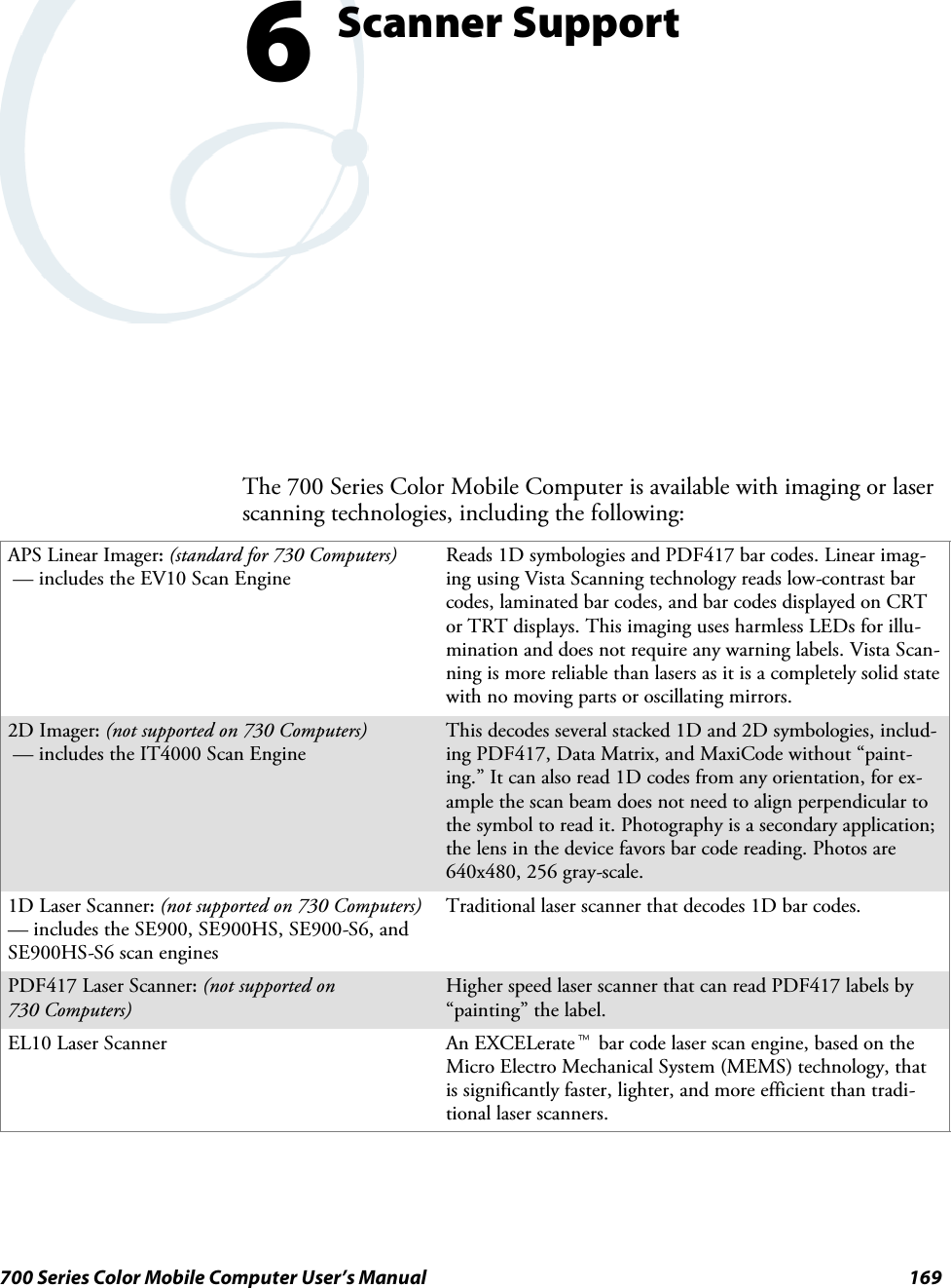

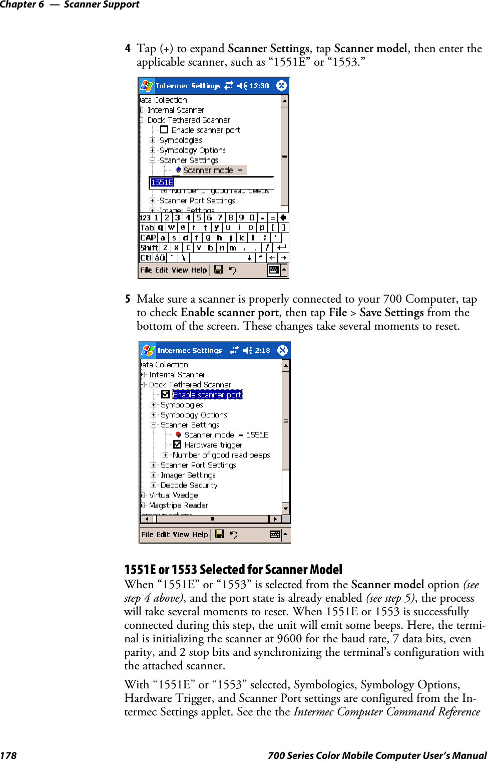
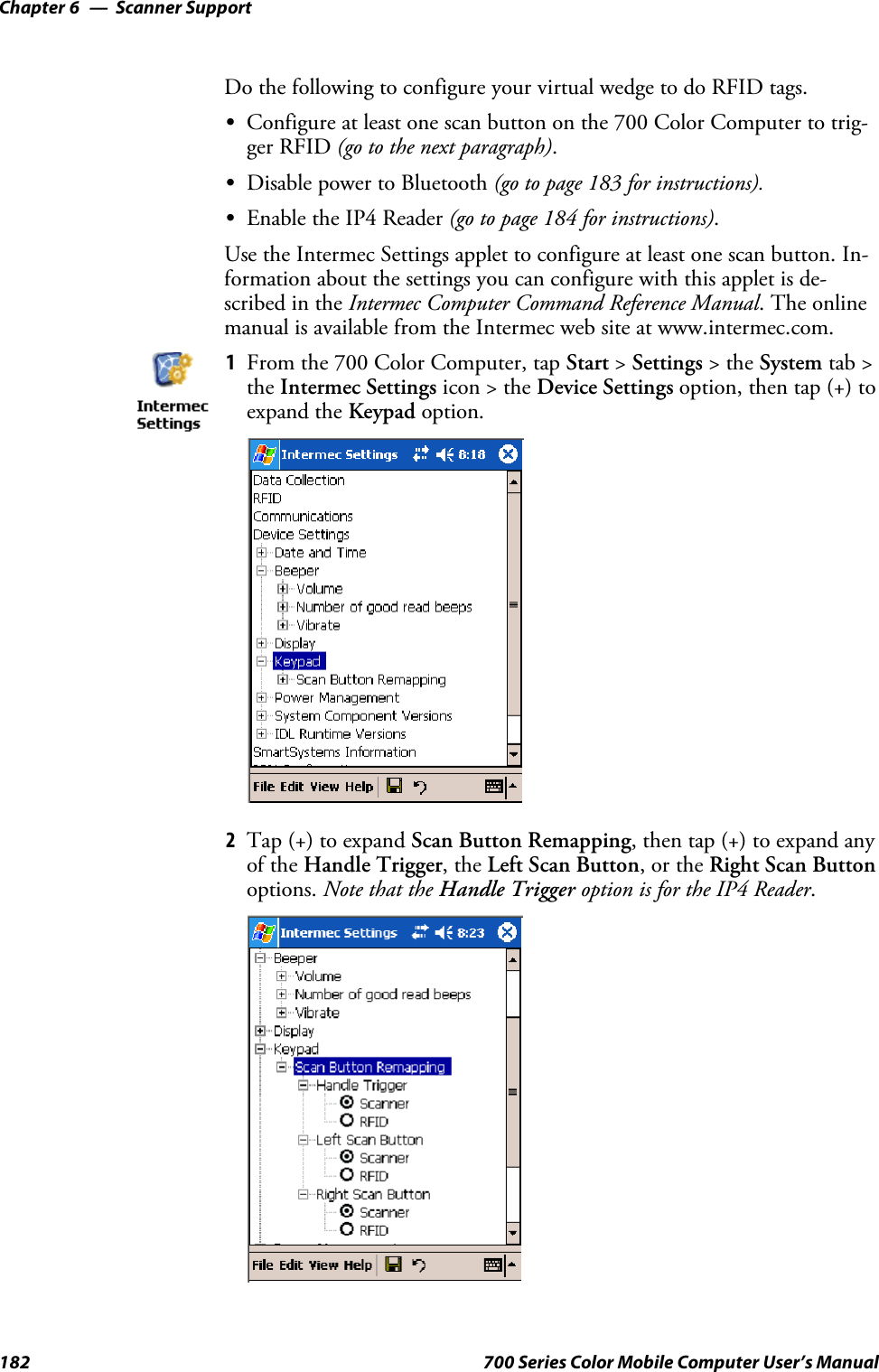

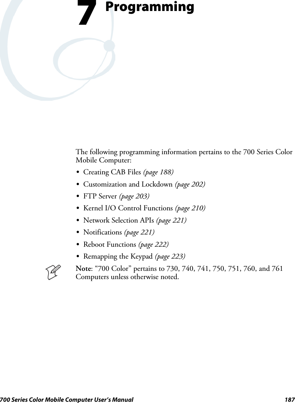
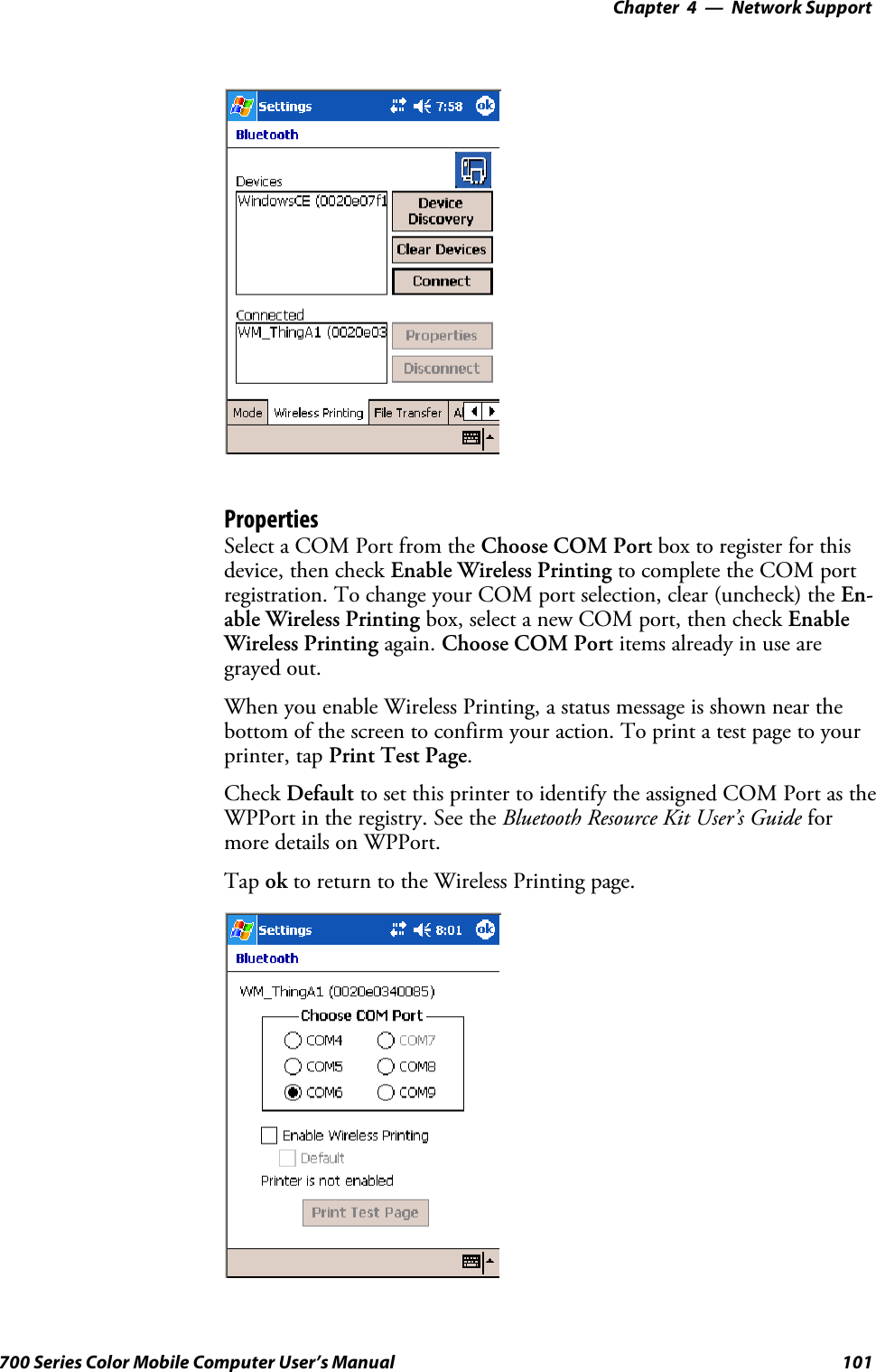
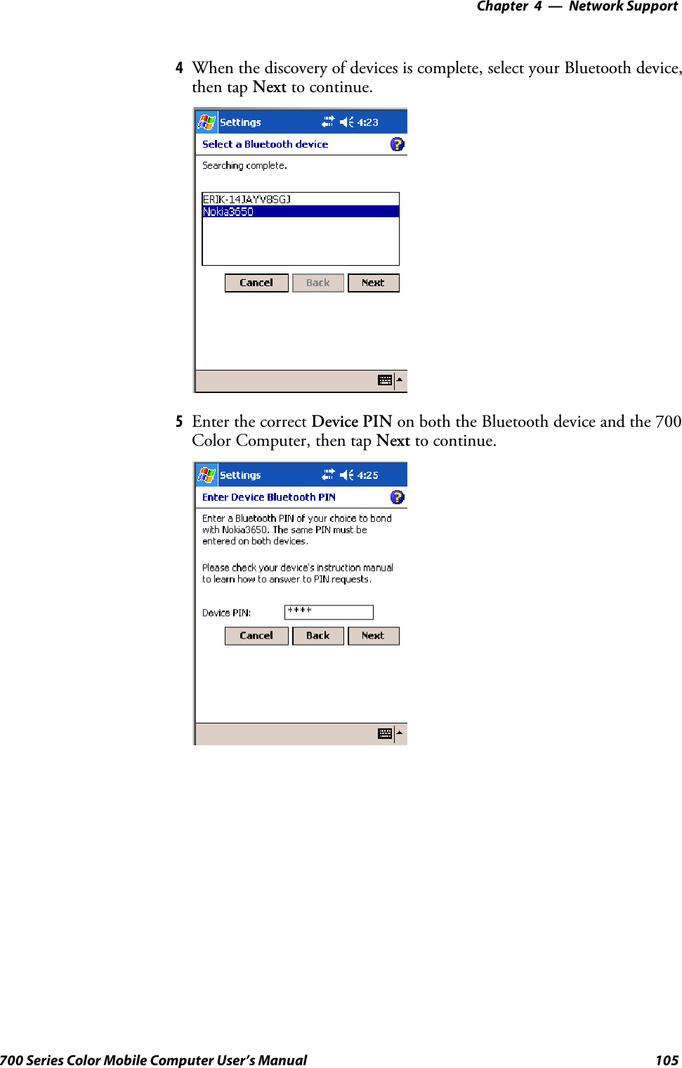
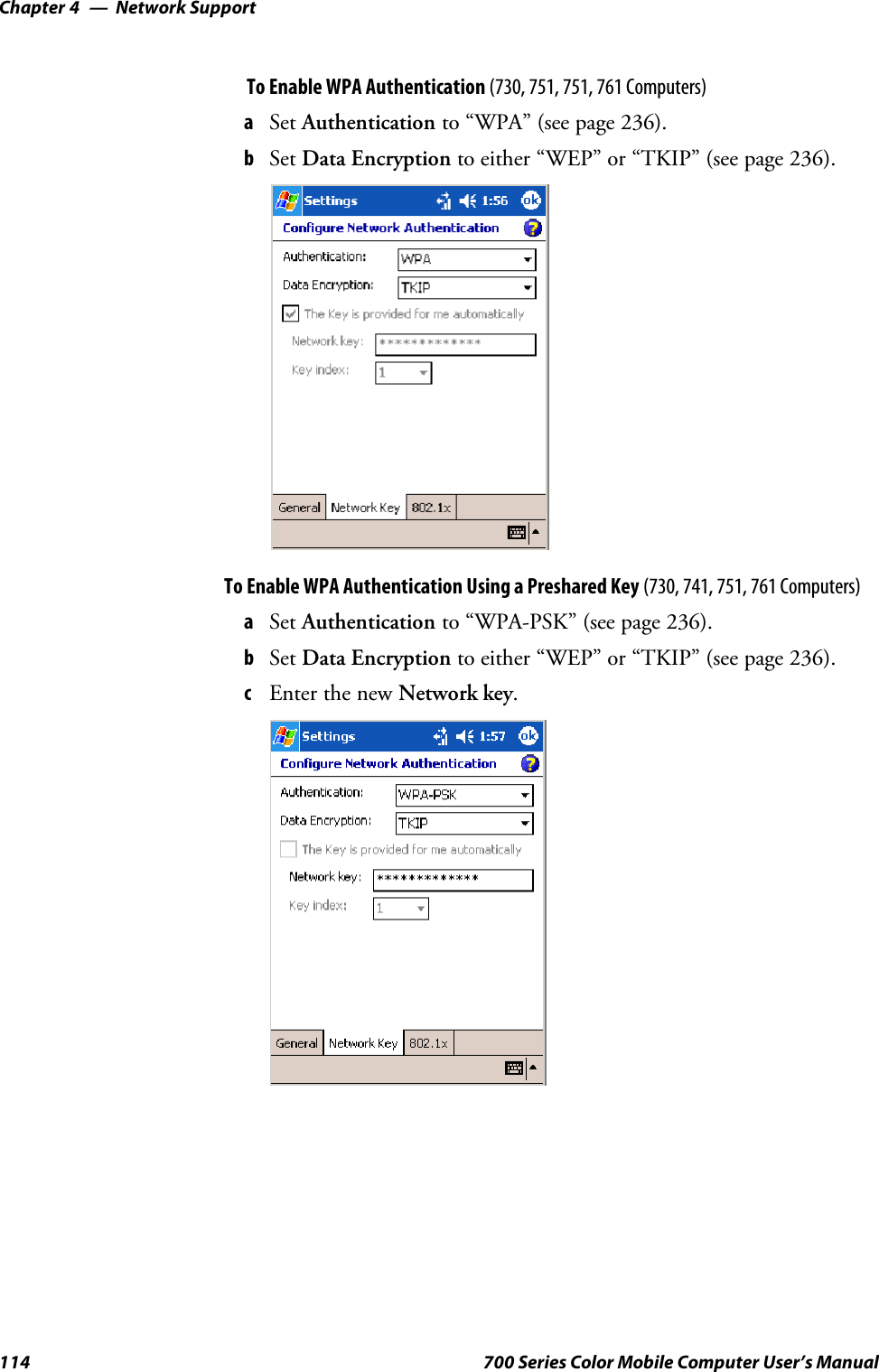
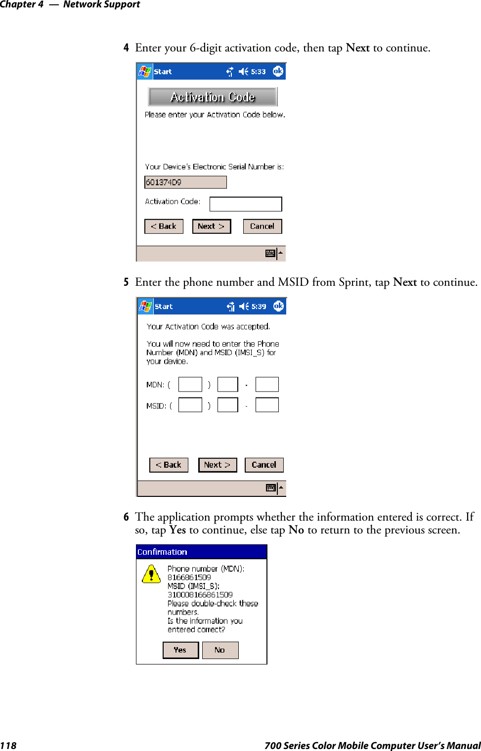
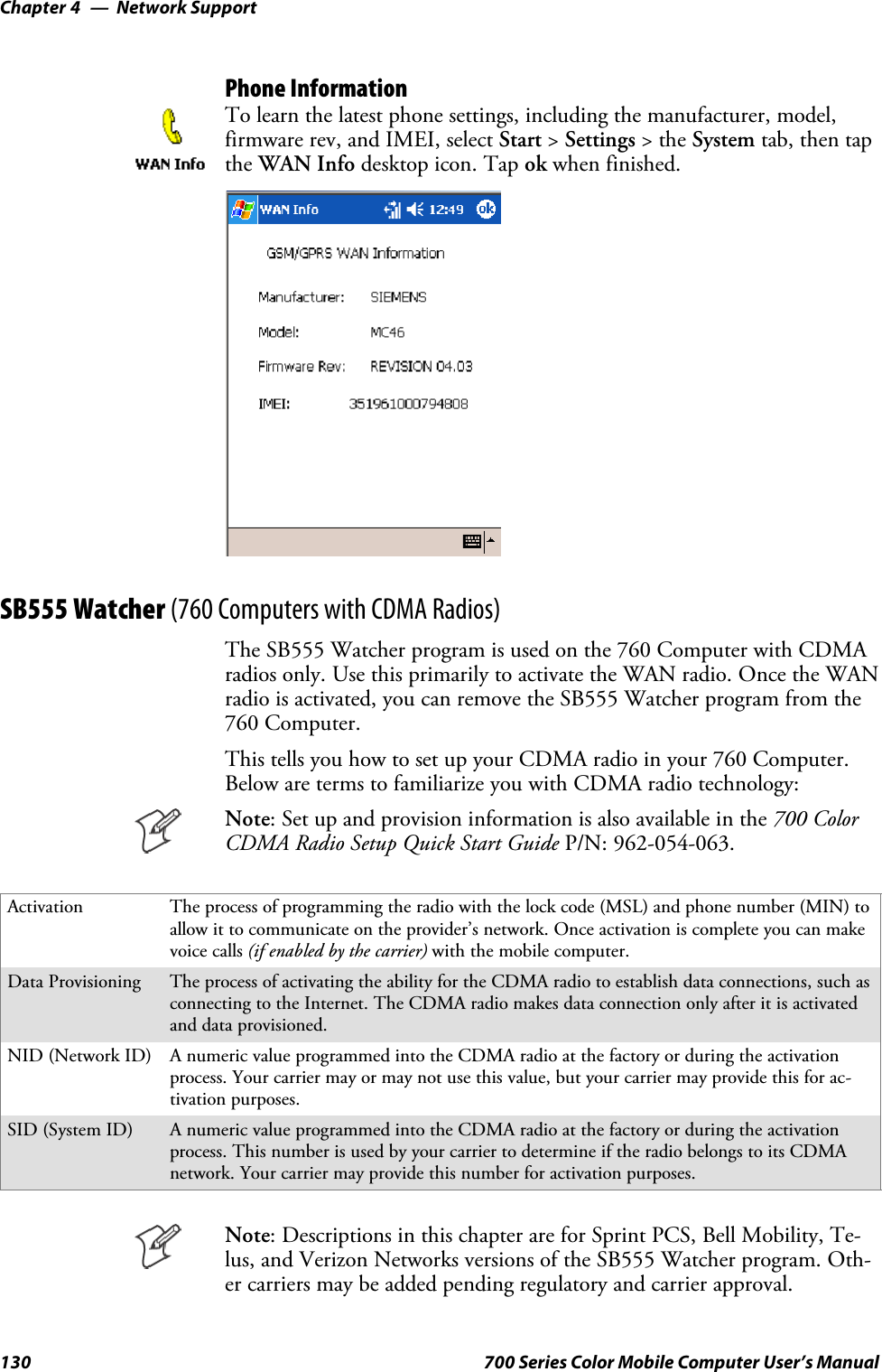
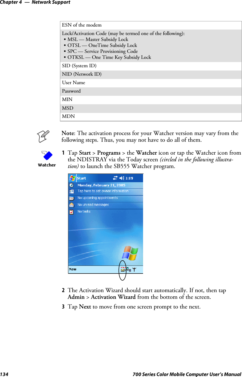
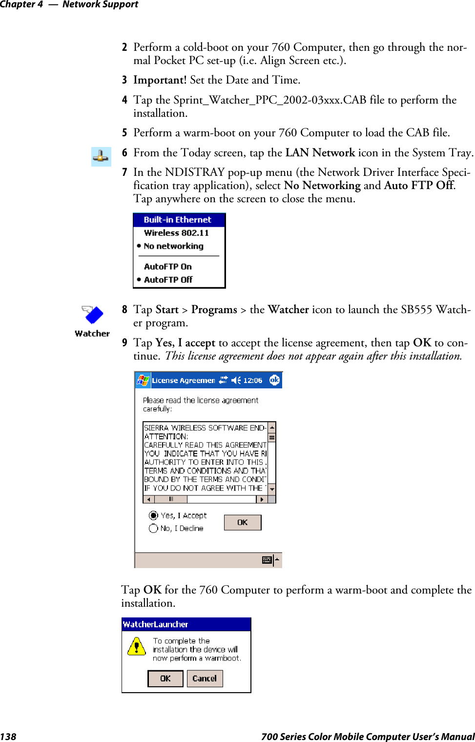
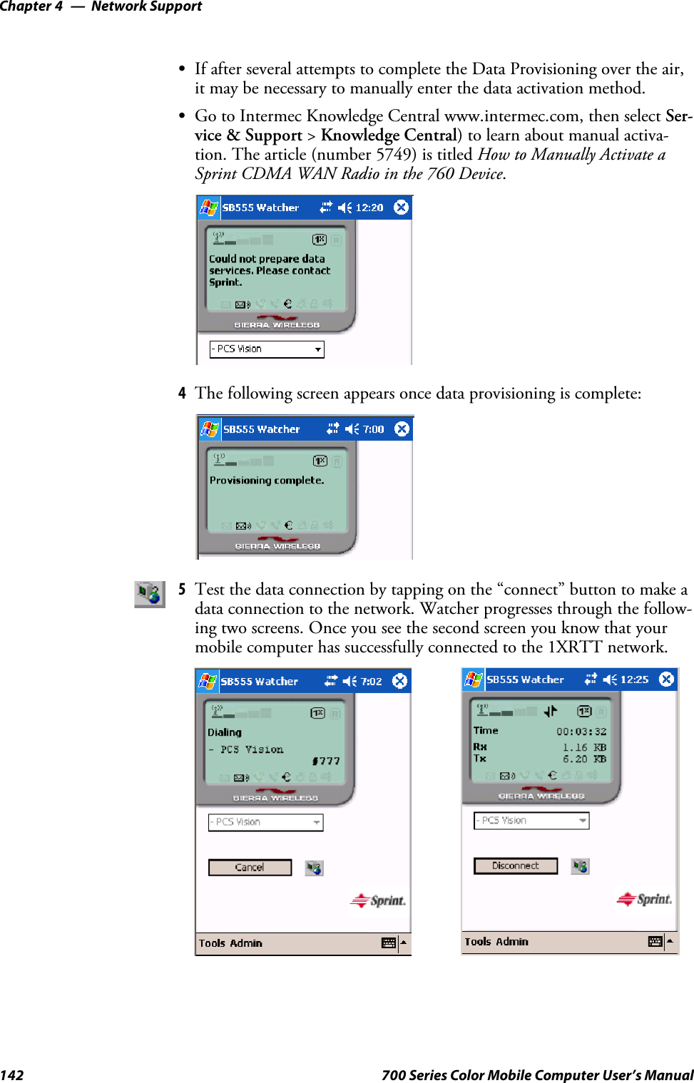
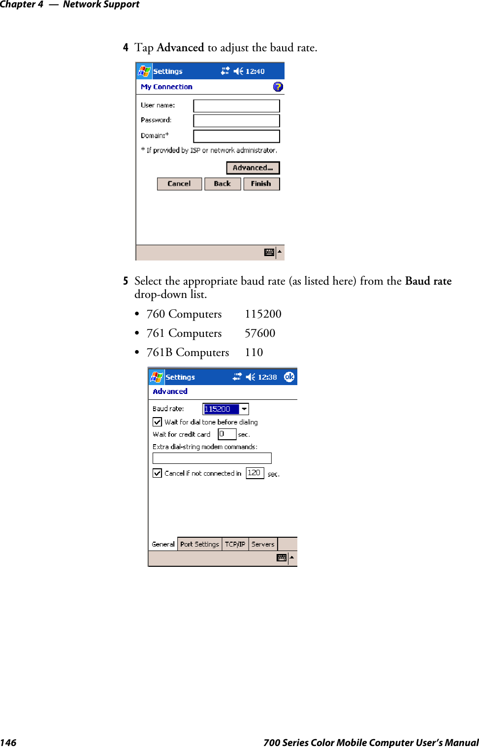
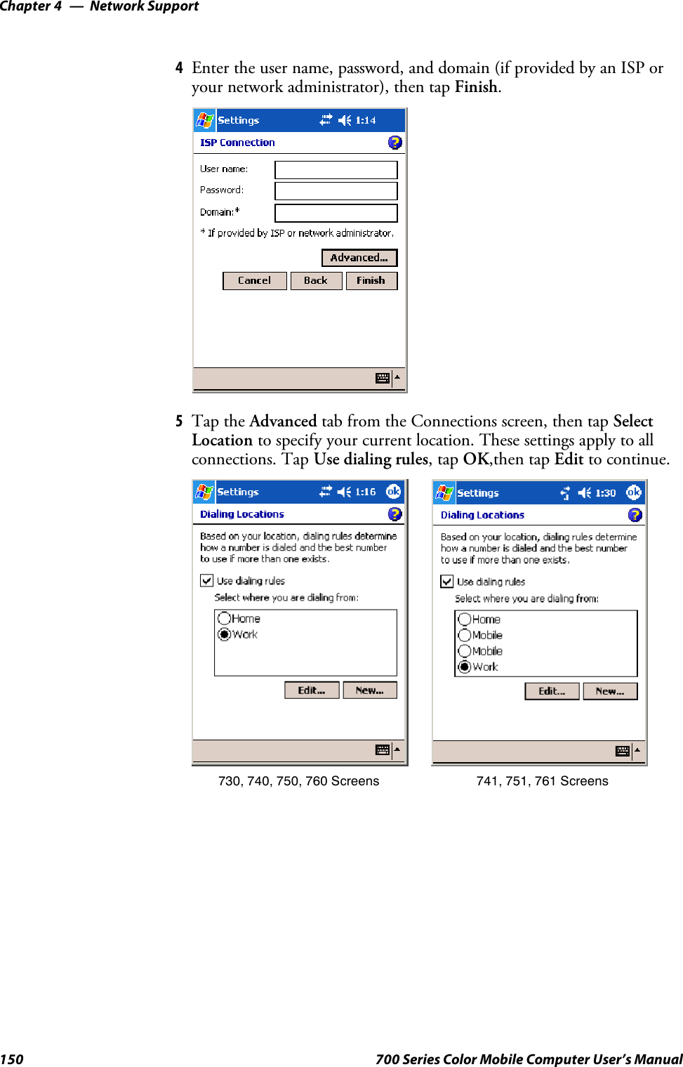
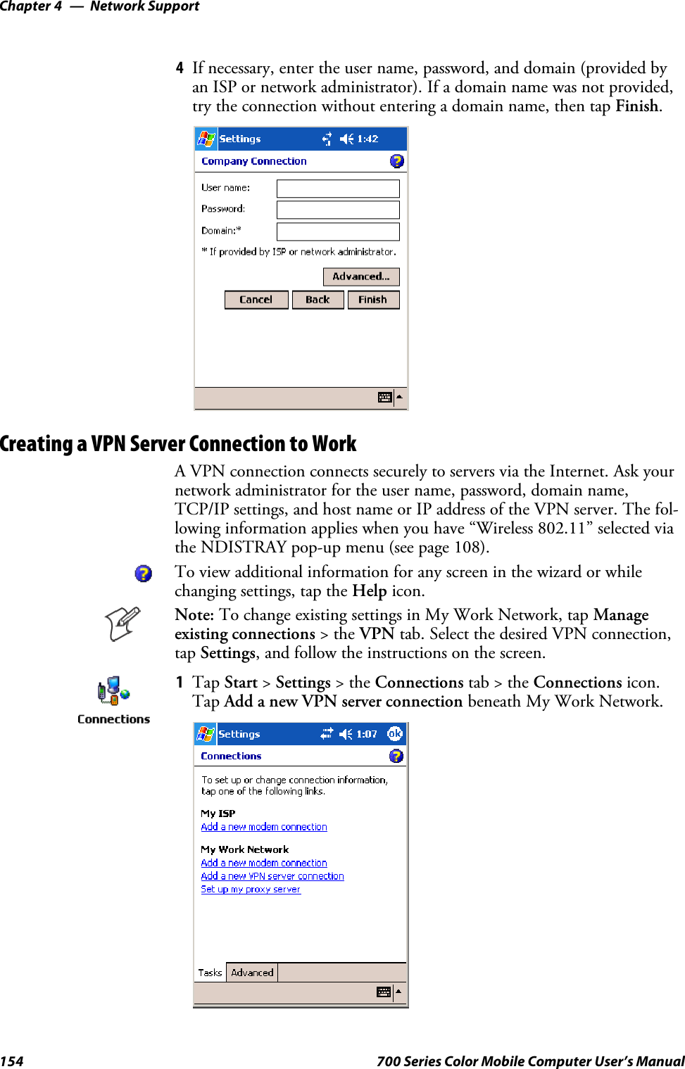
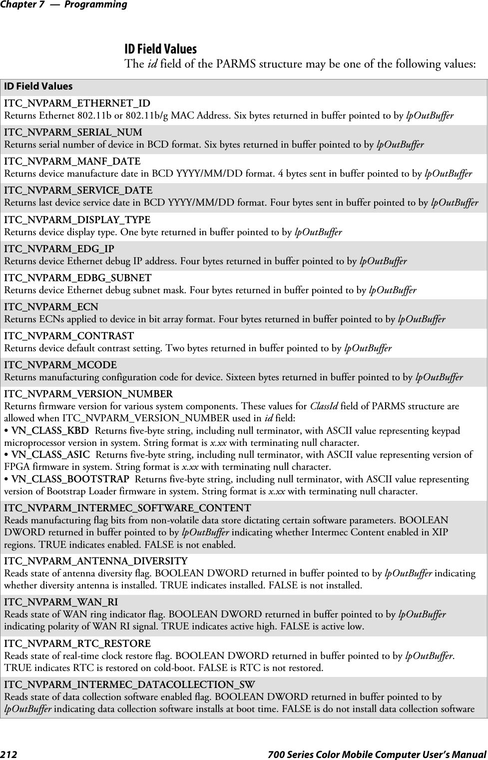
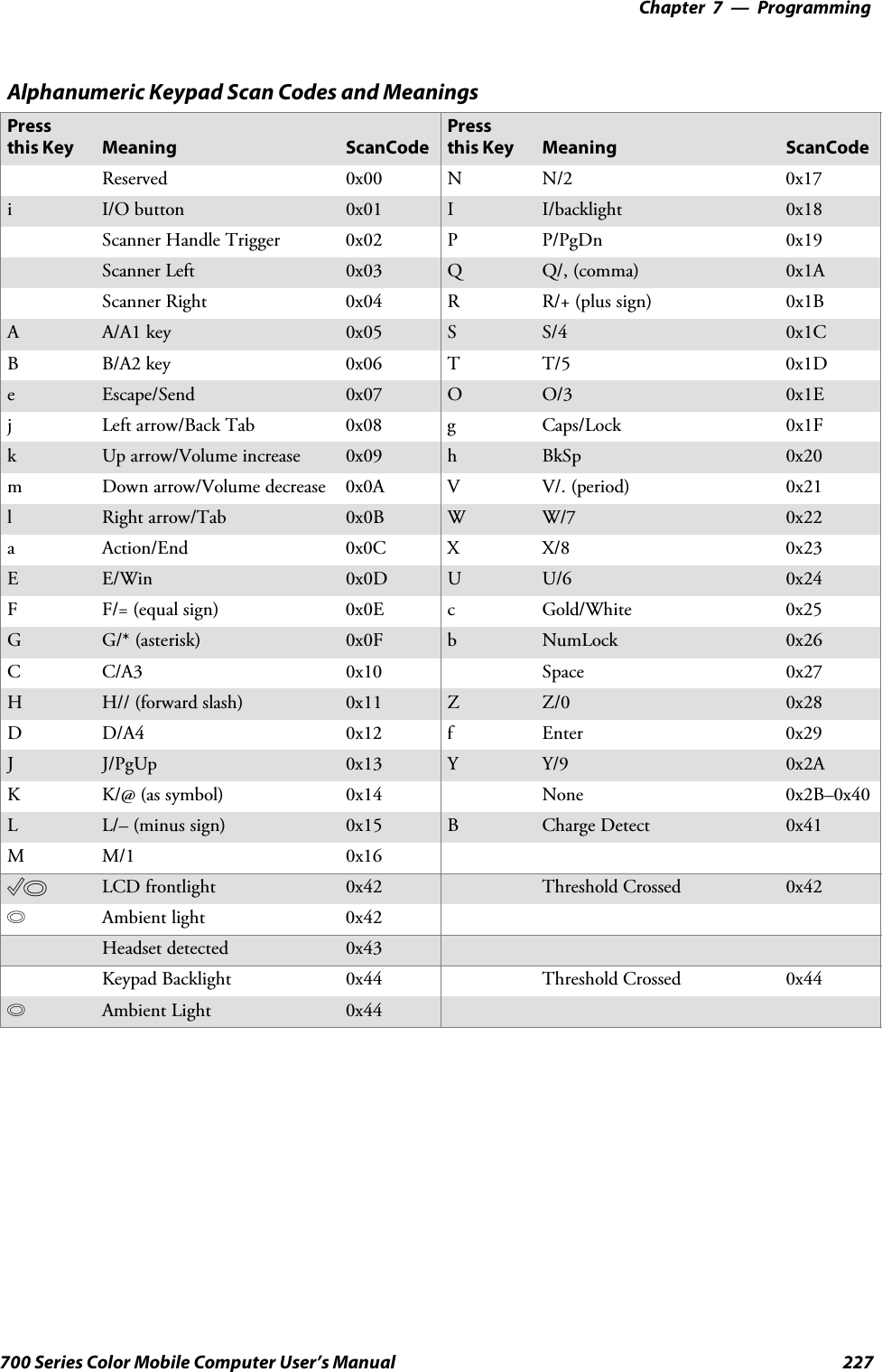
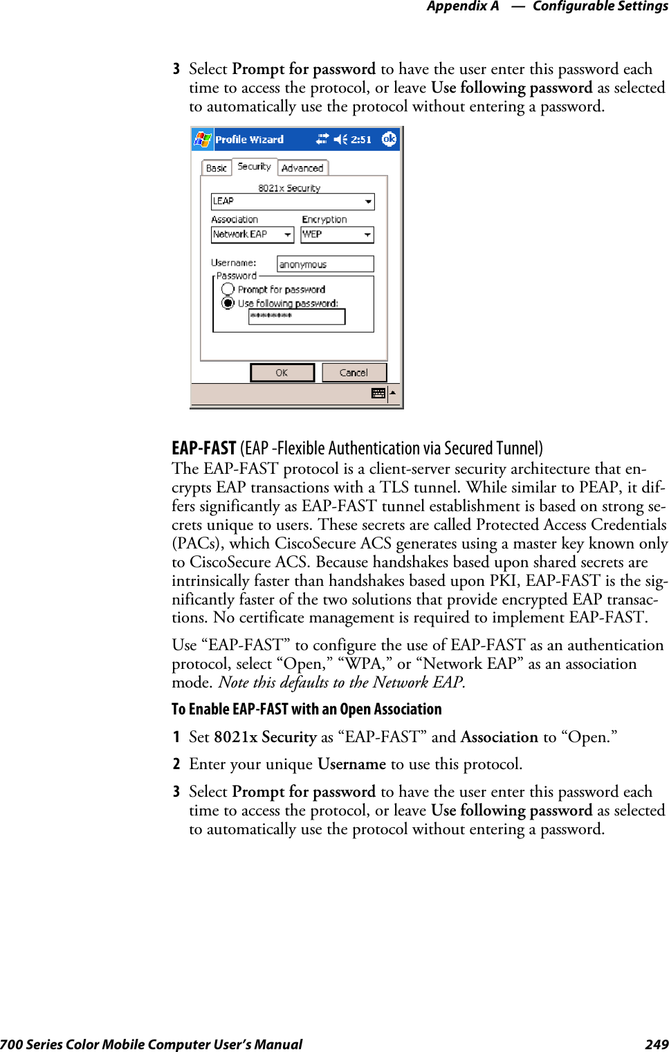
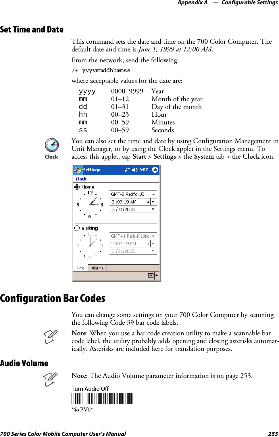
![ProgrammingChapter —7188 700 Series Color Mobile Computer User’s ManualCreating CAB FilesThe Windows CE operating system uses a .CAB file to install an applica-tion on a Windows CE-based device. A .CAB file is composed of multiplefiles that are compressed into one file. Compressing multiple files into onefile provides the following benefits:SAll application files are present.SA partial installation is prevented.SThe application can be installed from several sources, such as a desktopcomputer or a Web site.Use the CAB Wizard application (CABWIZ.EXE) to generate a .CAB filefor your application.Creating Device-Specific CAB FilesDo the following to create a device-specific .CAB file for an application, inthe order provided:1Create an .INF file with Windows CE-specific modifications (page188).2Optional Create a SETUP.DLL file to provide custom control of theinstallation process (page 197).3Use the CAB Wizard to create the .CAB file, using the .INF file, theoptional SETUP.DLL file, and the device-specific application files asparameters (page 201).Creating an .INF FileAn .INF file specifies information about an application for the CAB Wi-zard. Below are the sections of an .INF file:[Version]This specifies the creator of the file, version, and other relevant informa-tion.Required? YesSSignature:“signature_name”“$Windows NT$”SProvider:“INF_creator”The company name of the application, such as “Microsoft.”SCESignature“$Windows CE$”Example[Version]Signature = “$Windows NT$”Provider = “Intermec”CESignature = “$Windows CE$”](https://usermanual.wiki/Intermec-Technologies/MC75.Final-Users-Manual-part-2-of-2/User-Guide-730133-Page-88.png)
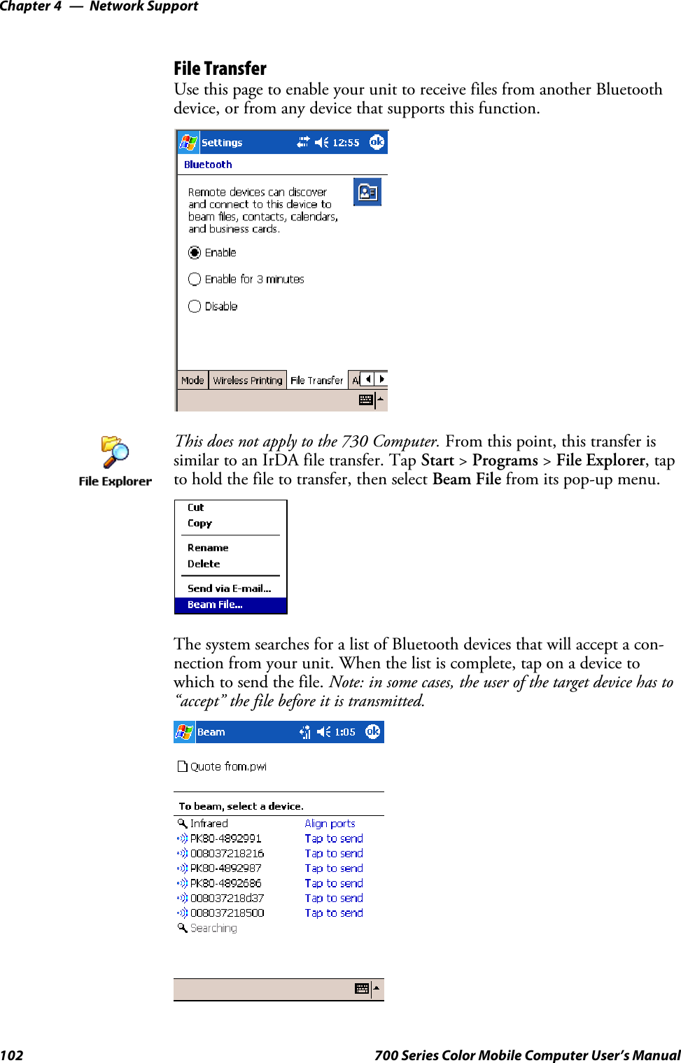
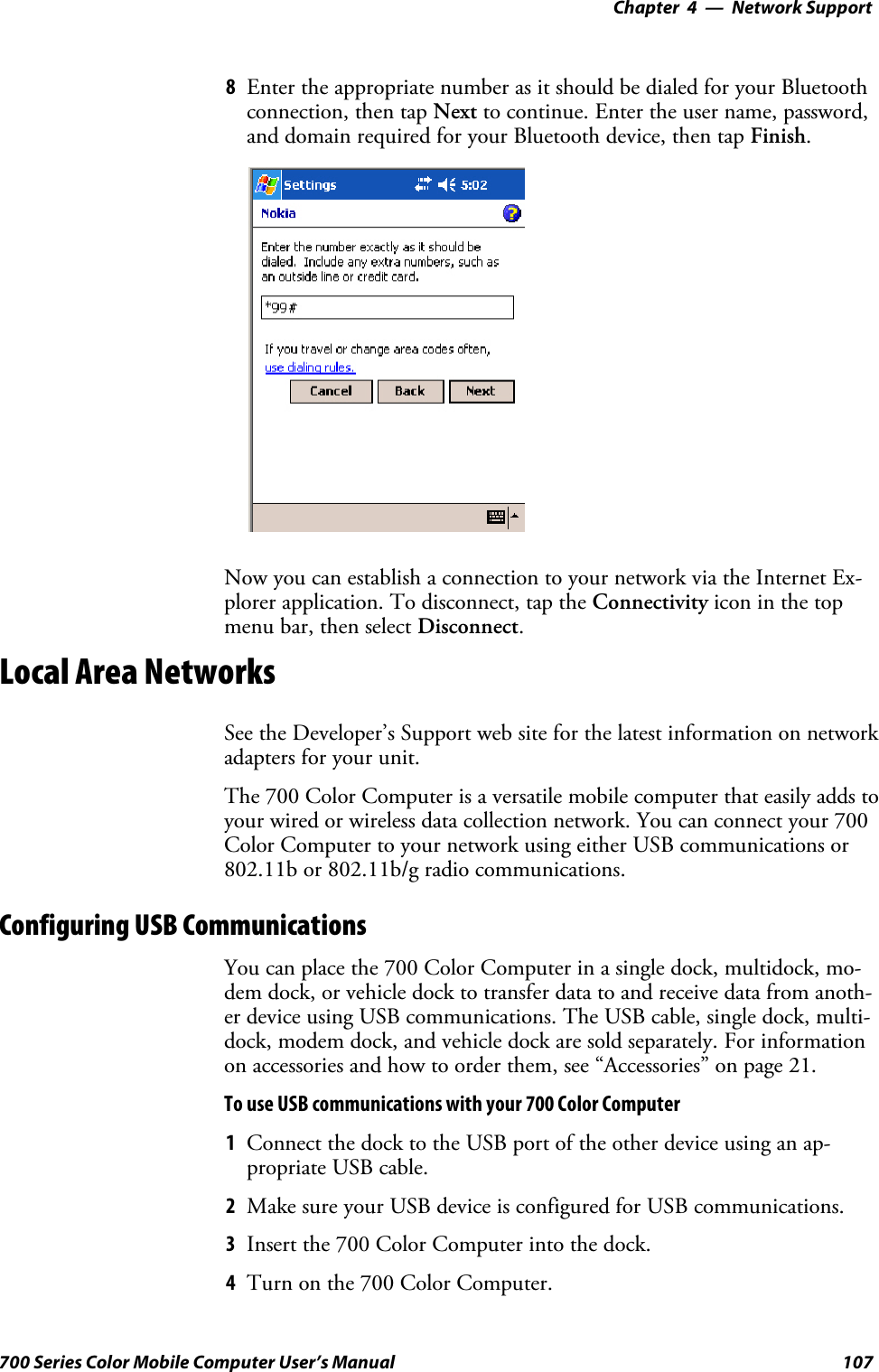
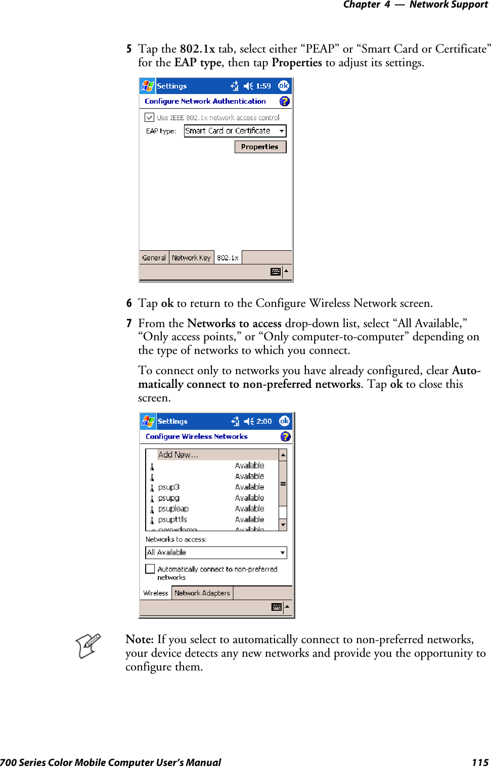
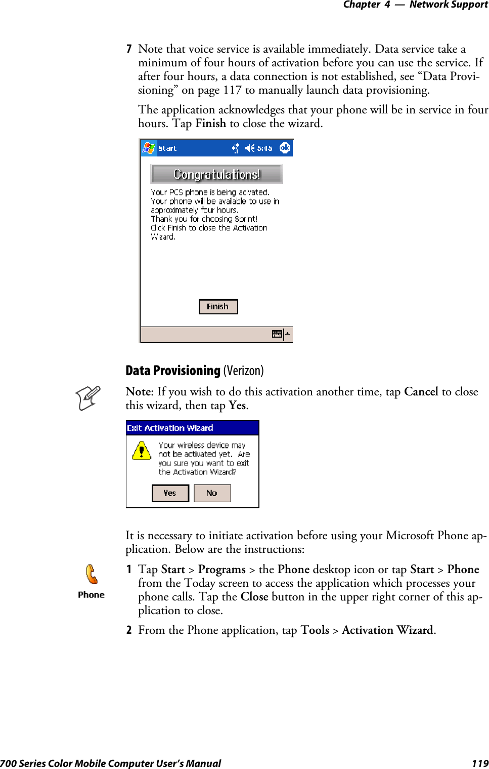
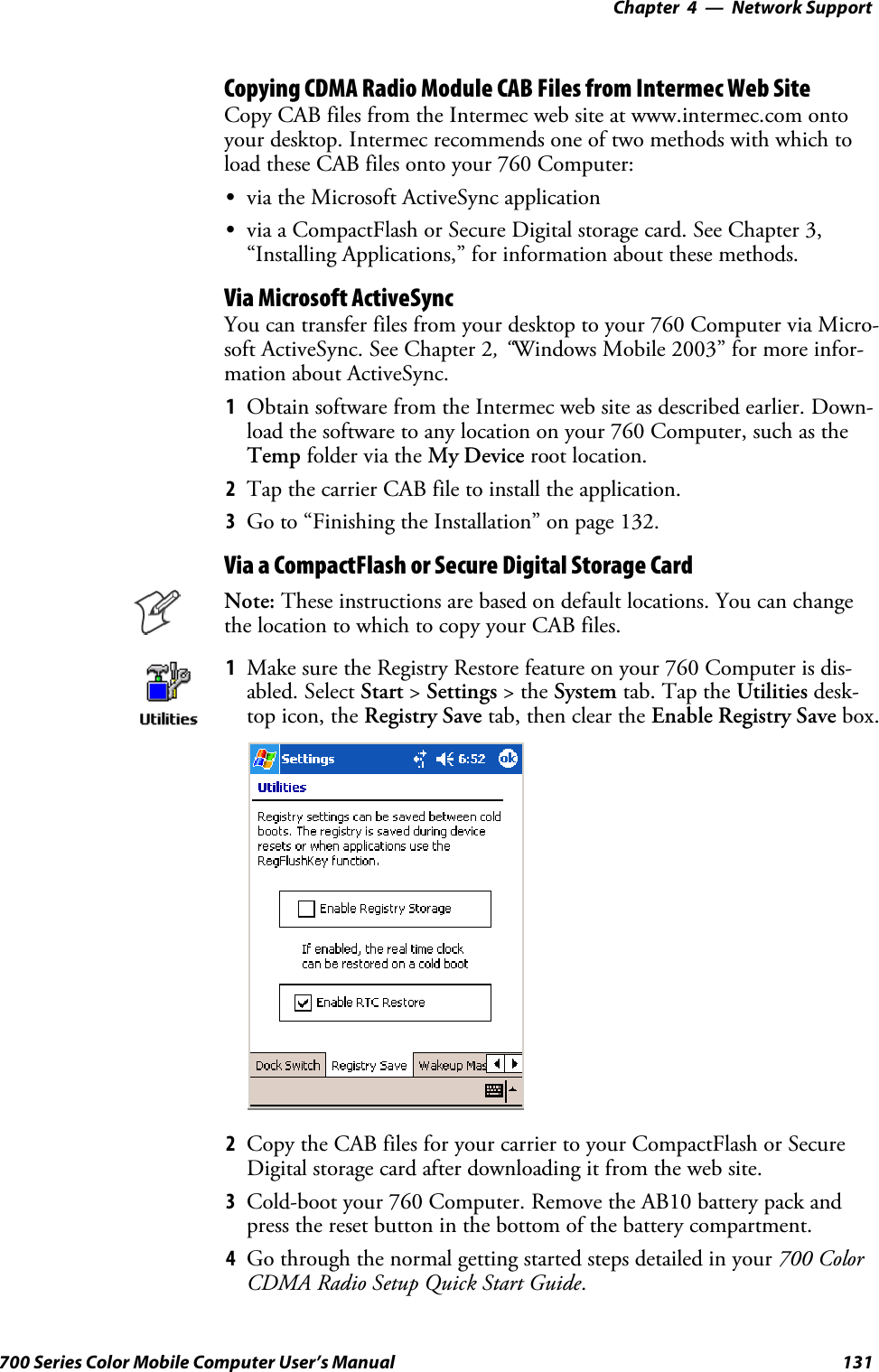
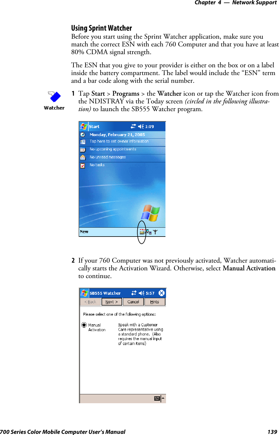
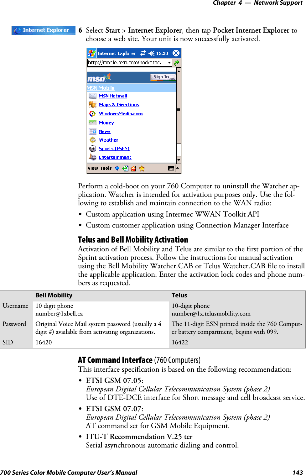
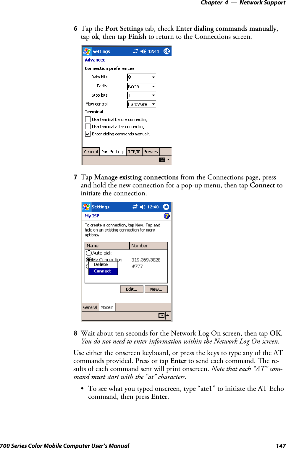
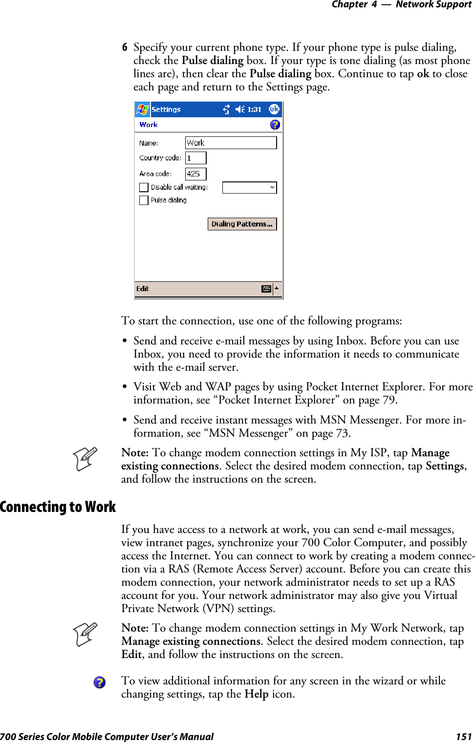
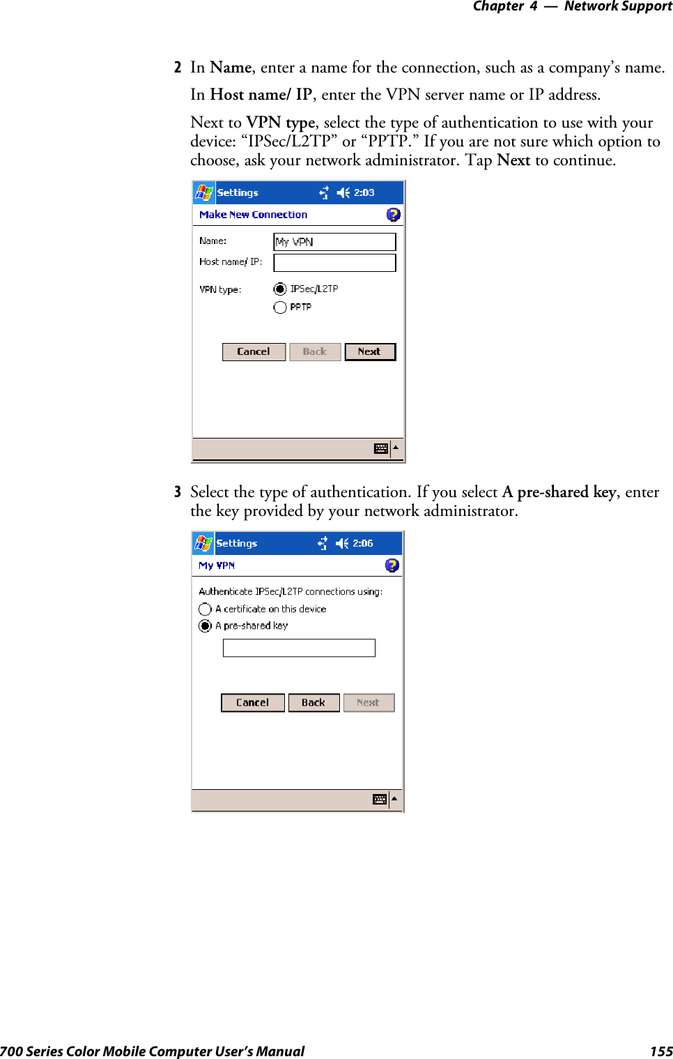
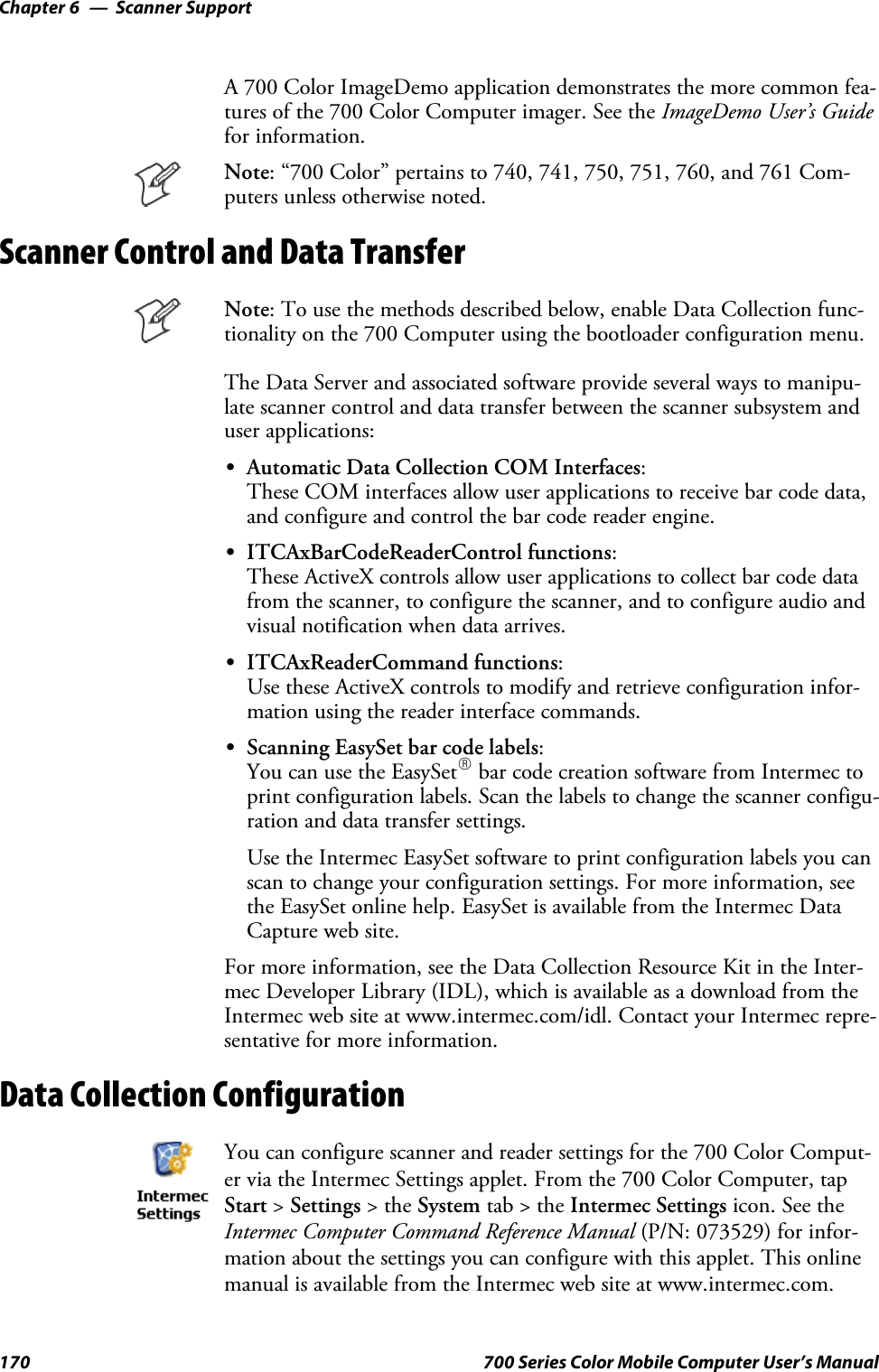
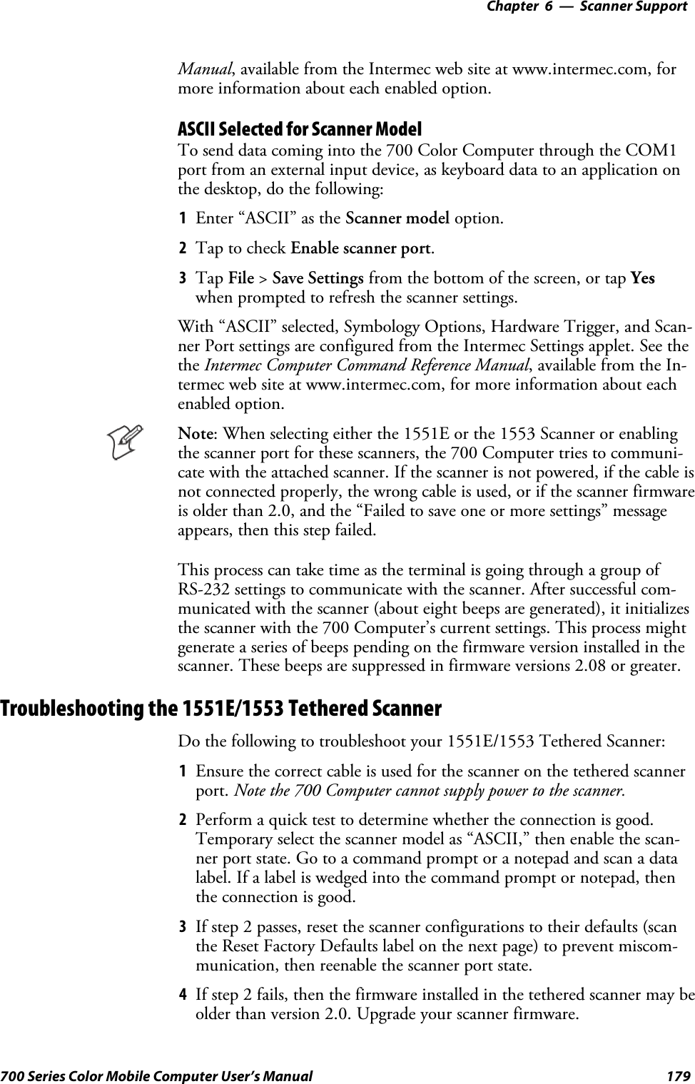
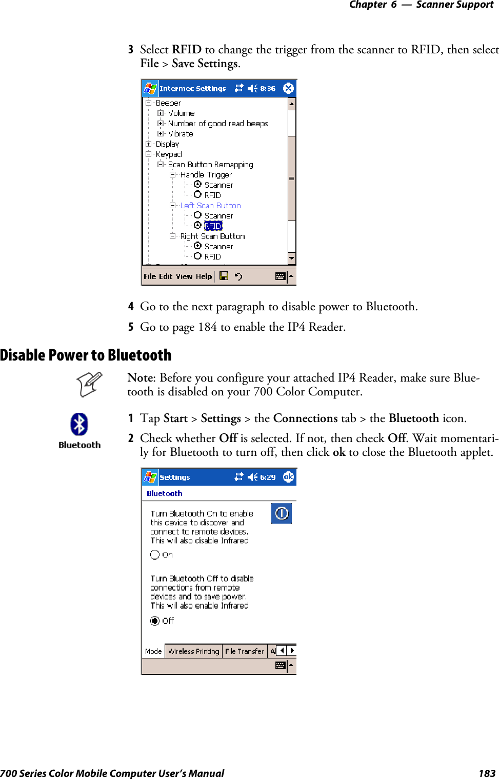
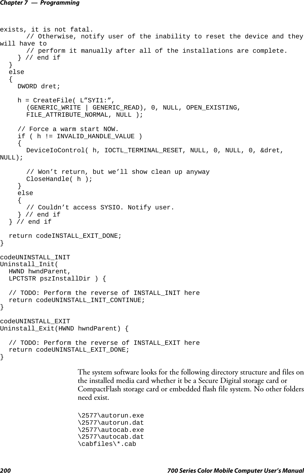
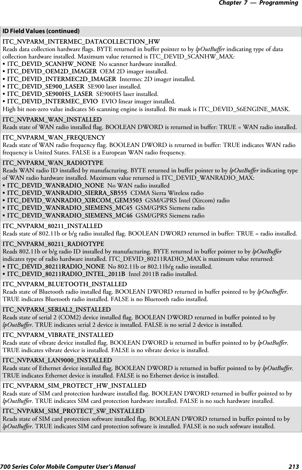
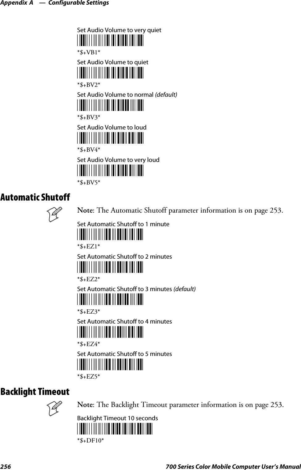
![Programming—Chapter 7189700 Series Color Mobile Computer User’s Manual[CEStrings]This specifies string substitutions for the application name and the defaultinstallation directory.Required? YesSAppName:app_nameName of the application. Other instances of %AppName% in the .INFfile are replaced with this string value, such as RP32.SInstallDir:default_install_dirDefault installation directory on the device. Other instances of %Install-Dir% in the .INF file are replaced with this string value. Example:\SDMMC_Disk\%AppName%Example[CEStrings]AppName=“Game Pack”InstallDir=%CE1%\%AppName%[Strings]This section is optional and defines one or more string keys. A string keyrepresents a string of printable characters.Required? NoSstring_key:valueString consisting of letters, digits, or other printable characters. Enclosevalue in double quotation marks ““”” if corresponding string key is usedin an item requiring double quotation marks. No string_keys is okay.Example[Strings]reg_path = Software\Intermec\My Test App[CEDevice]Describes the platform for the targeted application. All keys are optional.If a key is nonexistent or has no data, Windows CE does not perform anychecking except the UnsupportedPlatforms.IftheUnsupportedPlatforms keyexists but no data, the previous value is not overridden.Required? YesSProcessorType :processor_typeThe value that is returned by SYSTEMINFO.dwProcessorType.Forexample, the value for the ARM CPU is 2577SUnsupportedPlatforms:platform_family_nameThis lists known unsupported platform family names. If the namespecified in the [CEDevice.xxx] section is different from that in the[CEDevice] section, both platform_family_name values are unsupportedfor the microprocessor specified by xxx. That is, the list of unsupportedplatform family names is appended to the previous list of unsupportednames. Application Manager will not display the application for anunsupported platform. Also, a user will be warned during the setupprocess if the .CAB file is copied to an unsupported device.](https://usermanual.wiki/Intermec-Technologies/MC75.Final-Users-Manual-part-2-of-2/User-Guide-730133-Page-89.png)
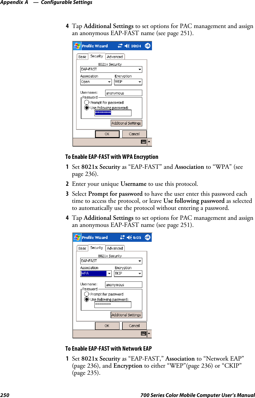
![ProgrammingChapter —7190 700 Series Color Mobile Computer User’s ManualExample[CEDevice]UnsupportedPlatforms = pltfrm1 ; pltfrm1 is unsupported[CEDevice.SH3]UnsupportedPlatforms = ; pltfrm1 is still unsupportedSVersionMin:minor_versionNumeric value returned by OSVERSIONINFO.dwVersionMinor. The.CAB file is valid for the currently connected device if the version ofthis device is greater than or equal to VersionMin.SVersionMax:major_versionNumeric value returned by OSVERSIONINFO.dwVersionMajor. The.CAB file is valid for the currently connected device if the version ofthis device is less than or equal to VersionMax.SBuildMin:build_numberNumeric value returned by OSVERSIONINFO.dwBuildNumber. The.CAB file is valid for the currently connected device if the version ofthis device is greater than or equal to BuildMin.SBuildMax:build_numberNumeric value returned by OSVERSIONINFO.dwBuildNumber. The.CAB file is valid for the currently connected device if the version ofthis device is less than or equal to BuildMax.ExampleThe following code example shows three [CEDevice] sections: one thatgives basic information for any CPU and two that are specific to the SH3and the MIPS microprocessors.[CEDevice] ; A “template” for all platformsUnsupportedPlatforms = pltfrm1 ; Does not support pltfrm1; The following specifies version 1.0 devices only.VersionMin = 1.0VersionMax = 1.0[CEDevice.ARM] ; Inherits all [CEDevice] settings; This will create a .CAB file specific to ARM devices.ProcessorType = 2577 ; ARM .cab file is valid for ARM microprocessors.UnsupportedPlatforms = ; pltfrm1 is still unsupported; The following overrides the version settings so that no version checking isperformed.VersionMin =VersionMax =[CEDevice.MIPS] ; Inherits all [CEDevice] settings; This will create a .CAB file specific to “MIPS” devices.ProcessorType = 4000 ; MIPS .CAB file is valid for MIPSmicroprocessor.UnsupportedPlatforms =pltfrm2 ; pltfrm1,pltfrm2 unsupported for MIPs .CABfile.Note: To create the two CPU-specific .CAB files for the SETUP.INF filein the previous example, run the CAB Wizard with the “/cpu arm mips”parameter.](https://usermanual.wiki/Intermec-Technologies/MC75.Final-Users-Manual-part-2-of-2/User-Guide-730133-Page-90.png)
![Programming—Chapter 7191700 Series Color Mobile Computer User’s Manual[DefaultInstall]This describes the default installation of your application. Note that underthis section, you will list items expanded upon later in this description.Required? YesSCopyfiles:copyfile_list_sectionMaps to files defined later in the .INF file, such as Files.App, Files.Font,and Files.Bitmaps.SAddReg:add_registry_sectionExample: RegSettings.AllSCEShortcuts:shortcut_list_sectionString that identifies one more section that defines shortcuts to a file, asdefined in the [CEShortcuts] section.SCESetupDLL:setup_DLLOptimal string that specifies a SETUP.DLL file. It is written by the In-dependent Software Vendor (ISV) and contains customized functionsfor operations during installation and removal of the application. Thefile must be specified in the [SourceDisksFiles] section.SCESelfRegister:self_reg_DLL_filenameString that identifies files that self-register by exporting the DllRegister-Server and DllUnregisterServer Component Object Model (COM)functions. Specify these files in the [SourceDiskFiles] section. Duringinstallation, if installation on the device fails to call the file’s exportedDllRegisterServer function, the file’s exported DllUnregisterServerfunction will not be called during removal.Example[DefaultInstall]AddReg = RegSettings.AllCEShortcuts = Shortcuts.All[SourceDiskNames]This section describes the name and path of the disk on which your ap-plication resides.Required? YesSdisk_ordinal:disk_label,,path1=,“App files” , C:\Appsoft\RP32\...2=,“Font files”,,C:\RpTools\...3=,“CE Tools” ,,C:\windows ce tools...SCESignature: “$Windows CE$”Example[SourceDisksNames] ; Required section1 = ,“Common files”,,C:\app\common ; Using an absolute path[SourceDisksNames.SH3]2 = ,“SH3 files”,,sh3 ; Using a relative path[SourceDisksNames.MIPS]2 = ,“MIPS files”,,mips ; Using a relative path](https://usermanual.wiki/Intermec-Technologies/MC75.Final-Users-Manual-part-2-of-2/User-Guide-730133-Page-91.png)
![ProgrammingChapter —7192 700 Series Color Mobile Computer User’s Manual[SourceDiskFiles]This describes the name and path of the files in which your applicationresides.Required? YesSfilename:disk_number[,subdir]RPM.EXE = 1,c:\appsoft\...WCESTART.INI = 1RPMCE212.INI = 1TAHOMA.TTF = 2Note:[,subdir] is relative to the location of the INF file.Example[SourceDisksFiles] ; Required sectionbegin.wav = 1end.wav = 1sample.hlp = 1[SourceDisksFiles.SH3]sample.exe = 2 ; Uses the SourceDisksNames.SH3 identification of 2.[SourceDisksFiles.MIPS]sample.exe = 2 ; Uses the SourceDisksNames.MIPS identification of 2.[DestinationDirs]This describes the names and paths of the destination directories for theapplication on the target device. Note Windows CE does not support directo-ry identifiers.Required? YesSfile_list_section:0,subdirString that identifies the destination directory. The following list showsthe string substitutions supported by Windows CE. Use these only forthe beginning of the path. \%CE1% \Program Files%CE2% \Windows%CE3% \My Documents%CE4% \Windows\Startup%CE5% \My Documents%CE6% \Program Files\Accessories%CE7% \Program Files\Communication%CE8% \Program Files\Games%CE9% \Program Files\Pocket Outlook%CE10% \Program Files\Office%CE11% \Windows\Start Menu\Programs%CE12% \Windows\Start Menu\Programs\Accessories%CE13% \Windows\Start Menu\Programs\Communications%CE14% \Windows\Start Menu\Programs\Games%CE15% \Windows\Fonts%CE16% \Windows\Recent%CE17% \Windows\Start Menu%InstallDir%](https://usermanual.wiki/Intermec-Technologies/MC75.Final-Users-Manual-part-2-of-2/User-Guide-730133-Page-92.png)
![Programming—Chapter 7193700 Series Color Mobile Computer User’s ManualContains the path to the target directory selected during installation. Itis declared in the [CEStrings] section%AppName%Contains the application name defined in the [CEStrings] section.Example[DestinationDirs]Files.Common = 0,%CE1%\My Subdir ; \Program Files\My SubdirFiles.Shared = 0,%CE2% ; \Windows[CopyFiles]This section, under the [DefaultInstall] section, describes the default filesto copy to the target device. Within the [DefaultInstall] section, files werelisted that must be defined elsewhere in the INF file. This section identi-fies that mapping and may contain flags.Required? YesScopyfile_list_section:destination_filename,[source_filename]The source_filename parameter is optional if it is the same as destina-tion_filename.Scopyfile_list_section:flagsThe numeric value that specifies an action to be done while copying fi-les. The following table shows values supported by Windows CE.Flag Value DescriptionCOPYFLG_WARN_IF_SKIP 0x00000001 Warn user if skipping a file is attempted after error.COPYFLG_NOSKIP 0x00000002 Do not allow a user to skip copying a file.COPYFLG_NO_OVERWRITE 0x00000010 Do not overwrite files in destination directory.COPYFLG_REPLACEONLY 0x00000400 Copy the source file to the destination directory only if thefile is already in the destination directory.CE_COPYFLG_NO_DATE_DIALOG 0x20000000 Do not copy files if the target file is newer.CE_COPYFLG_NODATECHECK 0x40000000 Ignore date while overwriting the target file.CE_COPYFLG_SHARED 0x80000000 Create a reference when a shared DLL is counted.Example[DefaultInstall.SH3]CopyFiles = Files.Common, Files.SH3[DefaultInstall.MIPS]CopyFiles = Files.Common, Files.MIPS[AddReg]This section, under the [DefaultInstall] section, is optional and describesthe keys and values that the .CAB file adds to the device registry. Withinthe [DefaultInstall] section, a reference may have been made to thissection, such as “AddReg=RegSettings.All”. This section defines theoptions for that setting.Required? No](https://usermanual.wiki/Intermec-Technologies/MC75.Final-Users-Manual-part-2-of-2/User-Guide-730133-Page-93.png)
![ProgrammingChapter —7194 700 Series Color Mobile Computer User’s ManualSadd_registry_section:registry_root_stringString that specifies the registry root location. The following list showsthe values supported by Windows CE.SHKCR Same as HKEY_CLASSES_ROOTSHKCU Same as HKEY_CURRENT_USERSHKLM Same as HKEY_LOCAL_MACHINESadd_registry_section:value_nameRegistry value name. If empty, the “default” registry value name is used.Sadd_registry_section:flagsNumeric value that specifies information about the registry key. Thefollowing table shows the values that are supported by Window CE.Flag Value DescriptionFLG_ADDREG_NOCLOBBER 0x00000002 If the registry key exists, do not overwrite it. Can be usedwith any of the other flags in this table.FLG_ADDREG_TYPE_SZ 0x00000000 REG_SZ registry data type.FLG_ADDREG_TYPE_MULTI_SZ 0x00010000 REG_MULTI_SZ registry data type. Value field that followscan be a list of strings separated by commas.FLG_ADDREG_TYPE_BINARY 0x00000001 REG_BINARY registry data type. Value field that followsmust be a list of numeric values separated by commas, onebyte per field, and must not use the 0x hexadecimal prefix.FLG_ADDREG_TYPE_DWORD 0x00010001 REG_DWORD data type. The noncompatible format in theWin32 Setup .INF documentation is supported.ExampleAddReg = RegSettings.All[RegSettings.All]HKLM,%reg_path%,,0x00000000,alpha ; <default> = “alpha”HKLM,%reg_path%,test,0x00010001,3 ; Test = 3HKLM,%reg_path%\new,another,0x00010001,6 ; New\another = 6[CEShortCuts]This section, a Windows CE-specific section under the [DefaultInstall]section, is optional and describes the shortcuts that the installation applica-tion creates on the device. Within the [DefaultInstall] section, a referencemay have been made to this section, such as “ShortCuts.All”. This sectiondefines the options for that setting.Required? NoSshortcut_list_section:shortcut_filenameString that identifies the shortcut name. It does not require the .LNKextension.Sshortcut_list_section:shortcut_type_flagNumeric value. Zero or empty represents a shortcut to a file; any non-zero numeric value represents a shortcut to a folder.](https://usermanual.wiki/Intermec-Technologies/MC75.Final-Users-Manual-part-2-of-2/User-Guide-730133-Page-94.png)
![Programming—Chapter 7195700 Series Color Mobile Computer User’s ManualSshortcut_list_section:target_file_pathString value that specifies the destination location. Use the target filename for a file, such as MyApp.exe, that must be defined in a file copylist. For a path, use a file_list_section name defined in the [Destination-Dirs] section, such as DefaultDestDir,orthe%InstallDir% string.Sshortcut_list_section:standard_destination_pathOptional string value. A standard %CEx% path or %InstallDir%.Ifnovalue is specified, the shortcut_list_section name of the current section orthe DefaultDestDir value from the [DestinationDirs] section is used.ExampleCEShortcuts = Shortcuts.All[Shortcuts.All]Sample App,0,sample.exe ; Uses the path in DestinationDirs. SampleApp,0,sample.exe,%InstallDir% ; The path is explicitly specified.Sample .INF File[Version] ; Required sectionSignature = “$Windows NT$”Provider = “Intermec Technologies Corporation”CESignature = “$Windows CE$”;[CEDevice];ProcessorType =[DefaultInstall] ; Required sectionCopyFiles = Files.App, Files.Fonts, Files.BitMaps, Files.Intl,Files.TelecomNcsCE, Files.Windows, Files.Import, Files.Export, Files.Work,Files.Database, Files.WinCE AddReg = RegSettings.All ;CEShortcuts =Shortcuts.All[SourceDisksNames] ; Required section1 = ,“App files” ,,c:\appsoft\...2 = ,”Font files” ,,c:\WinNT\Fonts3 = ,”CE Tools” ,,c:\windows ce tools\wce400\700ie\mfc\lib\x86[SourceDisksFiles] ; Required sectionrpm.exe = 1,C:\Appsoft\program\wce400\WCEX86Rel700wcestart.ini = 1rpmce212.ini = 1intermec.bmp = 1rpmlogo.bmp = 1rpmname.bmp = 1import.bmp = 1export.bmp = 1clock.bmp = 1printer.bmp = 1filecopy.bmp = 1readme.txt = 1lang_eng.bin = 1rpmdata.dbd = 1,database\wce1tahoma.ttf = 2mfcce212.dll = 3olece212.dll = 3olece211.dll = 1,c:\windows ce tools\wce400\NMSD61102.11\mfc\lib\x86rdm45wce.dll = 1,c:\rptools\rdm45wce\4_50\lib\wce400\wcex86relpicfmt.dll = 1,c:\rptools\picfmt\1_00\wce400\wcex86rel6110](https://usermanual.wiki/Intermec-Technologies/MC75.Final-Users-Manual-part-2-of-2/User-Guide-730133-Page-95.png)
![ProgrammingChapter —7196 700 Series Color Mobile Computer User’s Manualfmtctrl.dll = 1,c:\rptools\fmtctrl\1_00\wce400\wcex86rel6110ugrid.dll = 1,c:\rptools\ugrid\1_00\wce400\wcex86rel6110simple.dll = 1,c:\rptools\pspbm0c\1_00\wce400\wcex86relpsink.dll = 1,c:\rptools\psink\1_00\wce400\WCEX86RelMinDependencypslpwce.dll =1,c:\rptools\pslpm0c\1_00\wce400\WCEX86RelMinDependencynpcpport.dll = 1,c:\rptools\cedk\212_03\installable drivers\printer\npcp;dexcom.dll = 1,c:\rptools\psdxm0c\1_00\x86ncsce.exe = 1,c:\rptools\ncsce\1_04nrinet.dll = 1,c:\rptools\ncsce\1_04[DestinationDirs] ; Required section;Shortcuts.All = 0,%CE3% ; \Windows\DesktopFiles.App = 0,%InstallDir%Files.DataBase = 0,%InstallDir%\DataBaseFiles.BitMaps = 0,%InstallDir%\BitmapsFiles.Fonts = 0,%InstallDir%\FontsFiles.Intl = 0,%InstallDir%\IntlFiles.TelecomNcsCE = 0,%InstallDir%\Telecom\NcsCEFiles.Windows = 0,%InstallDir%\WindowsFiles.Import = 0,%InstallDir%\ImportFiles.Export = 0,%InstallDir%\ExportFiles.Work = 0,%InstallDir%\WorkFiles.WinCE = 0,\storage_card\wince[CEStrings] ; Required sectionAppName = Rp32InstallDir = \storage_card\%AppName%[Strings] ; Optional section;[Shortcuts.All];Sample App,0,sample.exe ; Uses the path in DestinationDirs.;Sample App,0,sample.exe,%InstallDir% ; The path is explicitly specified.[Files.App]rpm.exe,,,0rpm.ini,rpmce212.ini,,0mfcce212.dll,,,0olece212.dll,,,0olece211.dll,,,0rdm45wce.dll,,,0picfmt.dll,,,0fmtctrl.dll,,,0ugrid.dll,,,0simple.dll,,,0psink.dll,,,0pslpwce.dll,,,0npcpport.dll,,,0;dexcom.dll,,,0[Files.DataBase]rpmdata.dbd,,,0[Files.Fonts]tahoma.ttf,,,0[Files.BitMaps]intermec.bmp,,,0rpmlogo.bmp,,,0rpmname.bmp,,,0](https://usermanual.wiki/Intermec-Technologies/MC75.Final-Users-Manual-part-2-of-2/User-Guide-730133-Page-96.png)
![Programming—Chapter 7197700 Series Color Mobile Computer User’s Manualimport.bmp,,,0export.bmp,,,0clock.bmp,,,0printer.bmp,,,0filecopy.bmp,,,0[Files.Intl]lang_eng.bin,,,0[Files.TelecomNcsCE]ncsce.exe,,,0nrinet.dll,,,0[Files.Windows]readme.txt,,,0[Files.Import]readme.txt,,,0[Files.Export]readme.txt,,,0[Files.Work]readme.txt,,,0[Files.WinCE]wcestart.ini,,,0[RegSettings.All]HKLM,”SOFTWARE\Microsoft\Shell\AutoHide”,,0x00010001,1; Autohide the taskbar HKLM,”SOFTWARE\Microsoft\Shell\OnTop”,,0x00010001,0; Shell is not on topHKLM,”SOFTWARE\Microsoft\Clock”,SHOW_CLOCK,0x00010001,0; Clock is not on taskbarUsing Installation Functions in SETUP.DLLSETUP.DLL is an optional file that enables you to perform custom opera-tions during installation and removal of your application. The followinglist shows the functions that are exported by SETUP.DLL.Install_Init Called before installation begins. Use this function to check the application version when reinstal-ling an application and to determine if a dependent application is present.Install_Exit Called after installation is complete. Use this function to handle errors that occur during applica-tion installation.Uninstall_Init Called before the removal process begins. Use this function to close the application, if the applica-tion is running.Uninstall_Exit Called after the removal process is complete. Use this function to save database information to afile and delete the database and to tell the user where the user data files are stored and how to rein-stall the application.Note;Use[DefaultInstall] >CESelfRegister (page 191) in the .INF file topoint to SETUP.DLL.](https://usermanual.wiki/Intermec-Technologies/MC75.Final-Users-Manual-part-2-of-2/User-Guide-730133-Page-97.png)
![ProgrammingChapter —7198 700 Series Color Mobile Computer User’s ManualAfter the CAB File ExtractionCab files that need to cause a warm reset after cab extraction will need tocreate the __RESETMEPLEASE__.TXT file in the “\Windows” directory.The preferred method to create this file is within the DllMain portion ofthe SETUP.DLL file. It looks like this:#include <windows.h>#include <Tlhelp32.h>#include <winioctl.h>#include <ce_setup.h> // in the public SDK dir#define IOCTL_TERMINAL_RESET CTL_CODE (FILE_DEVICE_UNKNOWN,FILE_ANY_ACCESS,2050, METHOD_NEITHER)BOOL APIENTRY DllMain( HANDLE h, DWORD reason, LPVOID lpReserved ){return TRUE;} // DllMain//************************************************************************// $DOCBEGIN$// BOOL IsProcessRunning( TCHAR * pname );//// Description: Get process table snapshot, look for pname running.//// Arguments: pname - pointer to name of program to look for.// for example, app.exe.//// Returns: TRUE - process is running.// FALSE - process is not running.// $DOCEND$//************************************************************************BOOL IsProcessRunning( TCHAR * pname ){HANDLE hProcList;PROCESSENTRY32 peProcess;DWORD thDeviceProcessID;TCHAR lpname[MAX_PATH];if ( !pname || !*pname ) return FALSE;_tcscpy( lpname, pname );_tcslwr( lpname );hProcList = CreateToolhelp32Snapshot( TH32CS_SNAPPROCESS, 0 );if ( hProcList == INVALID_HANDLE_VALUE ) {return FALSE;} // end ifmemset( &peProcess, 0, sizeof(peProcess) );peProcess.dwSize = sizeof(peProcess);if ( !Process32First( hProcList, &peProcess)){CloseToolhelp32Snapshot( hProcList );return FALSE;} // end if](https://usermanual.wiki/Intermec-Technologies/MC75.Final-Users-Manual-part-2-of-2/User-Guide-730133-Page-98.png)
![Programming—Chapter 7199700 Series Color Mobile Computer User’s ManualthDeviceProcessID = 0;do {_tcslwr( peProcess.szExeFile );if ( _tcsstr( peProcess.szExeFile, lpname)){thDeviceProcessID = peProcess.th32ProcessID;break;} // end if} while ( Process32Next( hProcList, &peProcess ) );if ( ( GetLastError() == ERROR_NO_MORE_FILES ) && ( thDeviceProcessID == 0)){CloseToolhelp32Snapshot( hProcList );return FALSE;} // end ifCloseToolhelp32Snapshot( hProcList );return TRUE;} // IsProcessRunningcodeINSTALL_INIT Install_Init(HWND hwndParent,BOOL fFirstCall,BOOL fPreviouslyInstalled,LPCTSTR pszInstallDir ){return codeINSTALL_INIT_CONTINUE;}codeINSTALL_EXIT Install_Exit (HWND hwndParent,LPCTSTR pszInstallDir,WORD cFailedDirs,WORD cFailedFiles,WORD cFailedRegKeys,WORD cFailedRegVals,WORD cFailedShortcuts ){HANDLE h;TCHAR srcfile[MAX_PATH];TCHAR dstfile[MAX_PATH];if (cFailedDirs || cFailedFiles || cFailedRegKeys ||cFailedRegVals || cFailedShortcuts)return codeINSTALL_EXIT_UNINSTALL;if ( IsProcessRunning( L”autocab.exe” ) ){h = CreateFile( L”\\Windows\\__resetmeplease__.txt”,(GENERIC_READ | GENERIC_WRITE), 0, NULL, CREATE_ALWAYS,FILE_ATTRIBUTE_HIDDEN, NULL );if(h!=INVALID_HANDLE_VALUE )CloseHandle( h );else{// Couldn’t create the file. If it failed because the file already](https://usermanual.wiki/Intermec-Technologies/MC75.Final-Users-Manual-part-2-of-2/User-Guide-730133-Page-99.png)
![Programming—Chapter 7201700 Series Color Mobile Computer User’s ManualCreating CAB Files with CAB WizardAfter you create the .INF file and the optional SETUP.DLL file, use theCAB Wizard to create the .CAB file. Below is the command-line syntax:cabwiz.exe “inf_file” [/dest dest_directory] [/err error_file] [/cpu cpu_type[cpu_type]]A batch file in <program> directory, with these commands, works well:cabwiz.exe c:\appsoft\<program>\<inf_file_name>cd \appsoft\<program>“inf_file” The SETUP.INF file path.dest_directory The destination directory for the .CAB files. If no directory is specified, the .CAB files are createdin the “inf_file” directory.error_file File name for a log file that contains all warnings and errors that are encountered when the .CABfiles are compiled. If no file name is specified, errors are displayed in message boxes. If a file nameis used, the CAB Wizard runs without the user interface (UI); this is useful for automated builds.cpu_type Creates a .CAB file for each specified microprocessor tag, which is a label used in the Win32 SE-TUP.INF file to differentiate between different microprocessor types. The /cpu parameter, fol-lowed by multiple cpu_type values, must be the last qualifier in the command line.ExampleThis example creates .CAB files for the ARM and MIPS microprocessors,assuming the Win32 SETUP.INF file contains the ARM and MIPS tags:cabwiz.exe “c:\myfile.inf” /err myfile.err /cpu arm mipsNote: CABWIZ.EXE, MAKECAB.EXE, and CABWIZ.DDF (WindowsCE files available on the Windows CE Toolkit) must be installed in thesame directory on the desktop computer. Call CABWIZ.EXE using its fullpath for the CAB Wizard application to run correctly.Troubleshooting the CAB WizardTo identify and avoid problems that might occur when using the CABWizard, follow these guidelines:SUse %% for a percent sign (%) character when using this character inan .INF file string, as specified in Win32 documentation. This will notwork under the [Strings] section.SDo not use .INF or .CAB files created for Windows CE to install ap-plications on Windows-based desktop platforms.SEnsure the MAKECAB.EXE and CABWIZ.DDF files, included withWindows CE, are in the same directory as CABWIZ.EXE.SUse the full path to call CABWIZ.EXE.SDo not create a .CAB file with the MAKECAB.EXE file included withWindows CE. You must use CABWIZ.EXE, which usesMAKECAB.EXE to generate the .CAB files for Windows CE.SDo not set the read-only attribute for .CAB files.](https://usermanual.wiki/Intermec-Technologies/MC75.Final-Users-Manual-part-2-of-2/User-Guide-730133-Page-101.png)
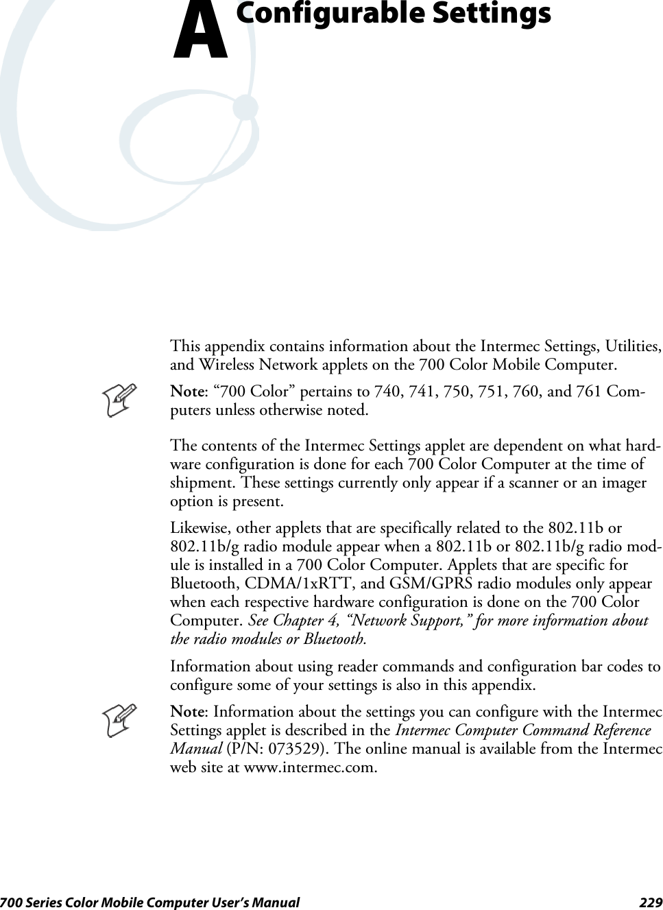
![Programming—Chapter 7203700 Series Color Mobile Computer User’s ManualFTP ServerFTP support is provided through the FTP Server applicationFTPDCE.EXE (MS Windows CE Versions) which is provided as part thebase system.FTPDCE is the Internet File Transfer Protocol (FTP) server process. Theserver can be invoked from an application or command line. Besides ser-vicing FTP client requests the FTP Server also send a “network announce-ment” to notify prospective clients of server availability.Note: You should consult the RFC959 specification for proper use ofsome of these commands at the following URL:Swww.ietf.org/rfc/rfc959.txt for the text version, orSwww.w3.org/Protocols/rfc959/ for an html versionDo the following to send commands:1Start an FTP client and connect to the device FTP server.2Log in with “intermec” as the user name and “cr52401” - the password.3From the FTP client, send the command.4Wait for a response.Synopsisftpdce [options ]Options–Aaddr (where addr is in the form of a.b.c.d) Sets the single target address to which to send the network an-nouncement. Default is broadcast.–Bbyte Sets the FTP data block size. Smaller sizes may be useful over slower links. Default is 65536.–Cname Sets the device name. Used by Intermec management software.–Fvalue Disables the default Intermec account. A value of “0” disables the account. Default is “1”.Note that disabling the default account without providing a working access control list on the serverwill result in a device that will not accept any FTP connections.–Hsec Sets the interval between network announcements in seconds.A value of “0” turns the network an-nouncement off. Default is 30 seconds.–Iaddr (where addr is in the form of a.b.c.d) Sets the preferred 6920 Communications Server (optional).–Llog (where log is either “0” or “1”) Sets the state of logging. Default is 0 (disabled).–Nsec Specifies the number of seconds to wait before initially starting FTP server services.–Pport Sets the UDP port on which the network announcement will be sent. Default port is 52401.–Qport Sets the port on which the FTP Server will listen for connections. Defaultportis21.–Rdir Sets the FTP mount point to this directory. Default is the root folder of the object store.–Tscrip Sets the script name for the 6920 Communications Server to process.–Uurl Sets the default URL for this device.–Z“parms” Sets extended parameters to be included in the network announcement.](https://usermanual.wiki/Intermec-Technologies/MC75.Final-Users-Manual-part-2-of-2/User-Guide-730133-Page-103.png)
![ProgrammingChapter —7206 700 Series Color Mobile Computer User’s ManualDELE Deletes a file.HELP Gives help information.LIST (This FTP request is the same as the ls -lgA command). Gives list files in a directory.MKD Makes a directory.MODE (AlwaysUsesBinary).Specifies data transfer mode.NLST (Not supported) Givesanamelistoffilesindirectory(thisFTPrequestisthesameasthels command).NOOP Does nothing.PASS Specifies a password.PWD Prints the current working directory.QUIT Terminates session.RETR Retrieves a file.RMD Removes a directory.RNFR Specifies rename-from file name.RNTO Specifies rename-to file name.STOR Stores a file.SYST Shows the operating system type of server system.TYPE (Binary transfers only.) Specifies the data transfer type with the Type parameter.USER Specifies user name.XCUP (Not Normally Used) Changes the parent directory of the current working directory.XCWD (Not Normally Used) Changes the current directory.XMKD (Not Normally Used) Creates a directory.XPWD (Not Normally Used) Prints the current working directory.XRMD (Not Normally Used) Removes a directory.SITE The following extended OEM commands are supported by the SITE request. For Microsoft FTP cli-ents, you can send site commands by preceding the command with “quote” such as “quote site status.”ATTRIB Gets or sets the attributes of a given file. (SITE ATTRIB)Usage QUOTE SITE ATTRIB [+R |-R][+A |-A ][+S |-S][+H |-H][[path]filename]+Sets an attribute.–Clears an attribute.RRead-only file attribute.AArchive file attribute.SSystem file attribute.HHidden file attribute.To retrieve the attributes of a file, only specify the file. The server response will be:200-AD SHRCEIX filename](https://usermanual.wiki/Intermec-Technologies/MC75.Final-Users-Manual-part-2-of-2/User-Guide-730133-Page-106.png)
![Programming—Chapter 7207700 Series Color Mobile Computer User’s ManualIf the flag exists in its position shown previously, it is set. Also, in addition to thevalues defined above, there is also defined:CCompressed file attribute.EEncrypted file attribute.IINROM file attribute.XXIPfileattribute(executeinROM,notshadowedinRAM).BOOT Reboots the server OS. This will cause the system on which the server is executing toreboot. The FTP Server will shut down cleanly before reboot. All client connectionswill be terminated. Cold boot is default except for the PocketPC build in which thedefault is warm boot. (SITE BOOT)Usage: QUOTE SITE BOOT [WARM |COLD]COPY Copies a file from one location to another. (SITE COPY)Usage: QUOTE SITE COPY [source][destination]Example: QUOTE SITE COPY ‘\Storage Card\one.dat’ ‘\Stor-age Card\two.dat’EXIT Exits the FTP Server. This command will shut down the FTP Server thus termina-ting all client connections. (SITE EXIT)Usage: QUOTE SITE EXITHELP Gives site command help information. (SITE HELP)Usage: QUOTE SITE HELP [command]KILL Terminates a running program. (SITE KILL)Usage: QUOTE SITE KILL [program |pid]LOG Opens or closes the program log. (SITE LOG)Usage: QUOTE SITE LOG [open [filename]| close]PLIST Lists the running processes (SITE PLIST)Usage: QUOTE SITE PLISTRUN Starts a program running. If the program to run has spaces in path or filename,wrappingthenamewithsinglequotesisrequired.Usage: QUOTE SITE RUN [program]Example: QUOTE SITE RUN ‘\Storage Card\app.exe’STATUS Returns the current settings of the FTP Server. MAC, serial number, model, IP ad-dress, network announcement information as well as OS memory usage are returned.(SITE STATUS)Usage: QUOTE SITE STATUSTIMEOUT Toggles idle timeout between 120 to 1200 seconds (2 to 20 minutes). If this timerexpires with no activity between the client and the server, the client connection willbe disconnected. If the optional seconds argument is supplied, the server will set theconnection timeout to the number of seconds specified. Default is 120 seconds or 2minutes. (SITE TIMEOUT)Usage: QUOTE SITE TIMEOUT [seconds]EKEY Gives site command electronic key information. (SITE HELP)Usage: QUOTE SITE EKEY [command]EVAL Gives site command electronic value information. (SITE HELP)Usage: QUOTE SITE EVAL [command]](https://usermanual.wiki/Intermec-Technologies/MC75.Final-Users-Manual-part-2-of-2/User-Guide-730133-Page-107.png)
![ProgrammingChapter —7208 700 Series Color Mobile Computer User’s ManualGVAL Gives site command general value information. (SITE HELP)Usage: QUOTE SITE GVAL [command]PVAL Gives site command value information. (SITE HELP)Usage: QUOTE SITE PVAL [command]The remaining FTP requests specified in RFC 959 are recognized, but notimplemented.The banner returned in the parenthetical portion of its greeting shows theversion number of the FTP Server as well as the MAC address, serial num-ber and operating system of the machine hosting the server.The FTP Server supports browsing from the latest Netscape and Microsoftweb browsers. Drag-and-drop capability is available using this environ-ment.The FTPDCMDS subdirectory contains commands to use from the webbrowser.SClick EXITME.BIN to execute a SITE EXIT command.SClick REBOOTME.BIN to execute SITE BOOT command.SUse the GET command on these files to have the FTP Server executethese commands.SSecurity:A customer configurable access control list may be installed on the700 Color Computer. This list will allow customers to restrict accessvia the FTP Server to users they wish and is in addition to defaultIntermec accounts that are disabled using the -F0 option at runtime.The access control list is named FTPDCE.TXT and is placed in thesame directory on the 700 Color Computer as the FTPDCE.EXEserver. The FTP Server encrypts this file to keep the information safefrom unauthorized users. This file is encrypted when the FTP Serveris started so a file that is placed onto the 700 Color Computer afterthe FTP Server starts will require a restart of the FTP Server to takeeffect.The format of the FTPDCE.TXT is as follows:FTPDCE:user1!passwd1<cr><lf>user2!passwd2<cr><lf>user3!passwd3<cr><lf>...Note: The user accounts and passwords are case sensitive.Once the access control list is encrypted on the 700 Color Computer,the FTP Server hides this file from users. Once an access control listis installed on the 700 Color Computer, a new one is not accepted bythe FTP Server until the previous one is removed. Encrypted accesscontrol lists are not portable between 700 Color Computers.Stopping the FTP Server from Your ApplicationTo allow application programmers the ability to programmatically shutdown the FTP Server, the FTP Server periodically tests to see if a namedevent is signaled. ITC_IFTP_STOP is the name of this event.](https://usermanual.wiki/Intermec-Technologies/MC75.Final-Users-Manual-part-2-of-2/User-Guide-730133-Page-108.png)
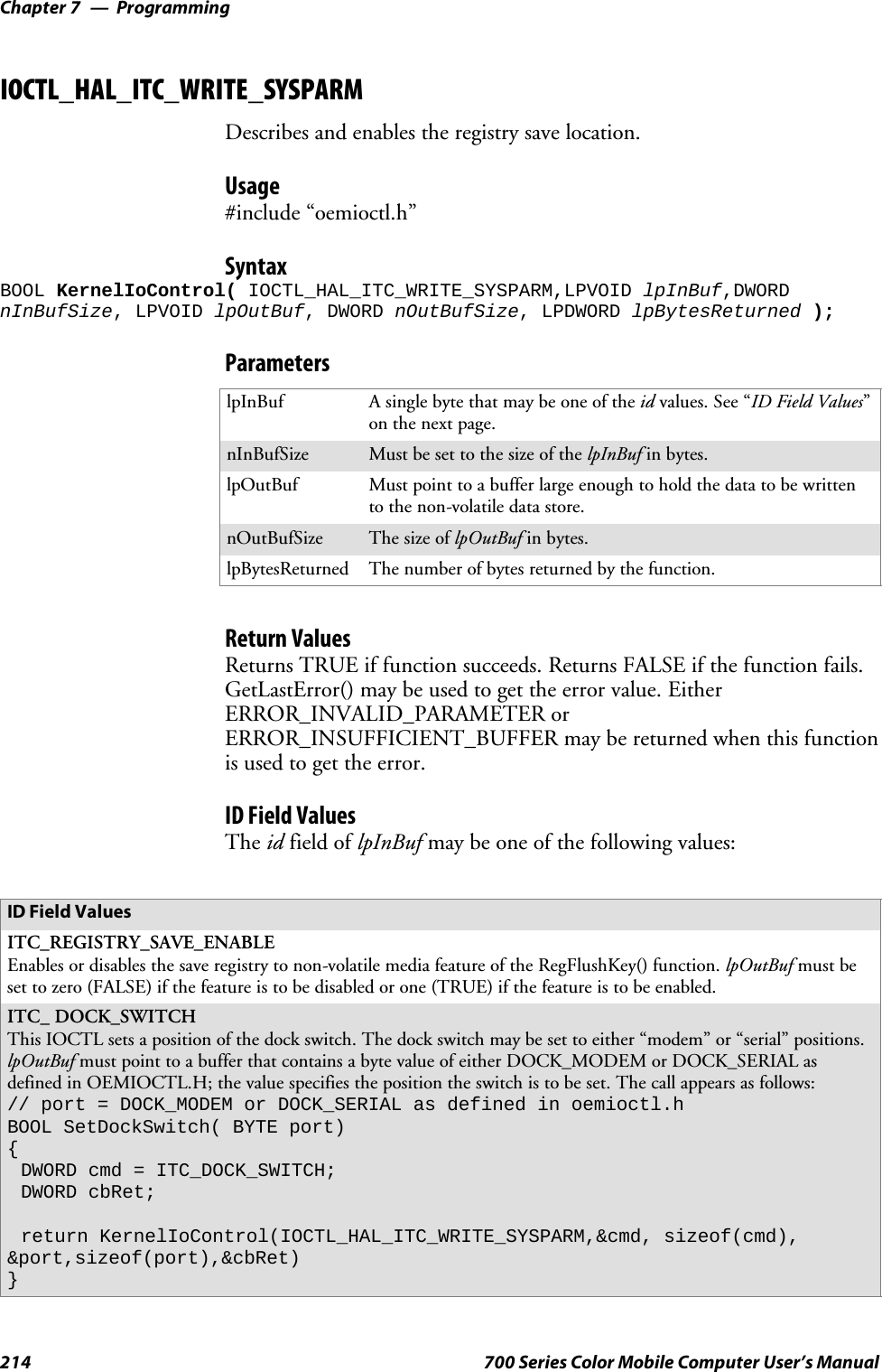
![ProgrammingChapter —7216 700 Series Color Mobile Computer User’s ManualIOCTL_HAL_GET_OAL_VERINFOReturns the HAL version information of the Pocket PC image.Usage#include “oemioctl.h”SyntaxBOOL KernelIoControl( IOCTL_HAL_GET_OAL_VERINFO,LPVOID lpInBuf,DWORDnInBufSize,LPVOID lpOutBuf,DWORD nOutBufSize,LPDWORD lpBytesReturned );ParameterslpInBuf Should be set to NULL.lpInBufSize Should be set to zero.lpOutBuf Must point to a VERSIONINFO structure as defined byOEMIOCTL.H. The fields should have these values:Scboemverinfo sizeof (tagOemVerInfo);Sverinfover 1Ssig; “ITC\0”Sid; ‘N’Stgtcustomer “”Stgtplat SeaRayStgtplatversion Current build version numberStgtcputype[8]; “Intel\0”Stgtcpu “PXA255\0”;Stgtcoreversion “”Sdate Build timeStime Build datenOutBufSize ThesizeofVERSIONINFOinbytes.lpBytesReturned Returns sizeof(PVERSIONINFO).Return ValuesReturns TRUE if function succeeds. Returns FALSE if the function fails.GetLastError() may be used to get the extended error value.IOCTL_HAL_GET_BOOTLOADER_VERINFOReturns the HAL version information of the Pocket PC image.Usage#include “oemioctl.h”SyntaxBOOL KernelIoControl( IOCTL_HAL_GET_OAL_VERINFO,LPVOID lpInBuf, DWORDnInBufSize,LPVOID lpOutBuf,DWORD nOutBufSize,LPDWORD lpBytesReturned );ParameterslpInBuf Should be set to NULL.nInBufSize Should be set to zero.](https://usermanual.wiki/Intermec-Technologies/MC75.Final-Users-Manual-part-2-of-2/User-Guide-730133-Page-116.png)
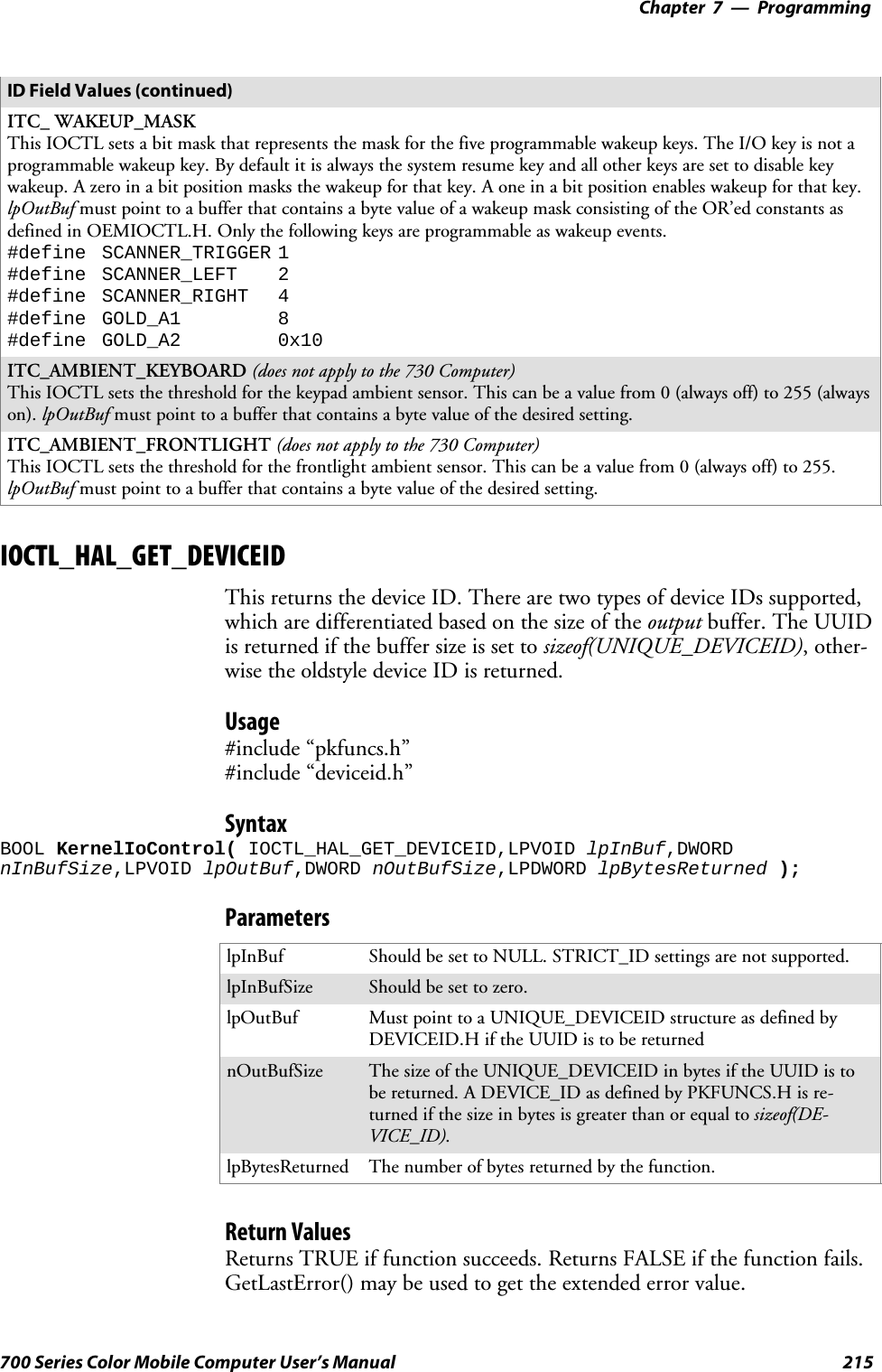
![Programming—Chapter 7217700 Series Color Mobile Computer User’s ManuallpOutBuf Must point to a VERSIONINFO structure as defined byOEMIOCTL.H. The fields should have these values:Scboemverinfo Sizeof (tagOemVerInfo);Sverinfover 1Ssig; “ITC\0”Sid; ‘B’Stgtcustomer “”Stgtplat SeaRayStgtplatversion Current build version number of thebootstrap loaderStgtcputype[8]; “Intel\0”;Stgtcpu “PXA255\0”Stgtcoreversion “”Sdate Build timeStime Build datenOutBufSize ThesizeofVERSIONINFOinbytes.lpBytesReturned The number of bytes returned to lpOutBuf.Return ValuesReturns TRUE if function succeeds. Returns FALSE if the function fails.GetLastError() may be used to get the extended error value.IOCTL_HAL_WARMBOOTCauses the system to perform a warm-boot. The object store is retained.Usage#include “oemioctl.h”SyntaxBOOL KernelIoControl( IOCTL_HAL_WARMBOOT,LPVOID lpInBuf,DWORDnInBufSize,LPVOID lpOutBuf,DWORD nOutBufSize,LPDWORD lpBytesReturned );ParameterslpInBuf Should be set to NULL.lpInBufSize Should be set to zero.lpOutBuf Should be NULL.nOutBufSize Should be zero.Return ValuesNone.IOCTL_HAL_COLDBOOTCauses the system to perform a cold-boot. The object store is cleared.Usage#include “oemioctl.h”SyntaxBOOL KernelIoControl( IOCTL_HAL_COLDBOOT,LPVOID lpInBuf,DWORDnInBufSize,LPVOID lpOutBuf,DWORD nOutBufSize,LPDWORD lpBytesReturned );](https://usermanual.wiki/Intermec-Technologies/MC75.Final-Users-Manual-part-2-of-2/User-Guide-730133-Page-117.png)
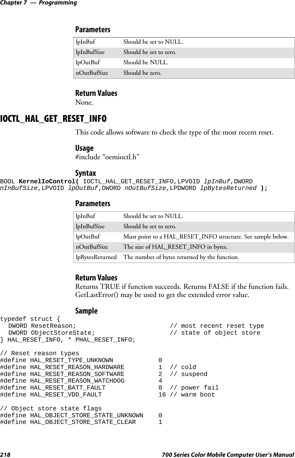
![ProgrammingChapter —7220 700 Series Color Mobile Computer User’s ManualIOCTL_PROCESSOR_INFORMATIONReturns processor information.Usage#include “pkfuncs.h”SyntaxBOOL KernelIoControl( IOCTL_PROCESSOR_INFORMATION,LPVOID lpInBuf,DWORDnInBufSize,LPVOID lpOutBuf,DWORD nOutBufSize,LPDWORD lpBytesReturned );ParameterslpInBuf Should be set to NULL.nInBufSize Should be set to zero.lpOutBuf Should be a pointer to the PROCESSOR_INFO structure. Itsstructure stores information describing the CPU more descriptively.typedef __PROCESSOR_INFO {WORD wVersion; // Set to value 1WCHAR szProcessorCore[40]; // “ARM\0”WORD wCoreRevision; // 4WCHAR szProcessorName[40]; // “PXA255\0”WORD wProcessorRevision; // 0WCHAR szCatalogNumber[100]; // 0WCHAR szVendor[100]; // “Intel Corporation\0”DWORD dwInstructionSet; // 0DWORD dwClockSpeed; // 400}nOutBufSize Should be set to sizeof(PROCESSOR_INFO) in bytes.lpBytesReturned Returns sizeof(PROCESSOR_INFO);Return ValuesReturns TRUE if function succeeds. Returns FALSE if the function fails.GetLastError() may be used to get the extended error value.IOCTL_GET_CPU_IDReturns Xscale processor ID.Usage#include “oemioctl.h”SyntaxBOOL KernelIoControl( IOCTL_GET_CPU_ID,LPVOID lpInBuf, DWORD nInBufSize,LPVOIDlpOutBuf,DWORD nOutBufSize,LPDWORD lpBytesReturned );ParameterslpInBuf ShouldpointtoaCPUIdInfostructuredefinedinOEMIOCTL.H.lpInBufSize Should be sizeof(CPUIdInfo).](https://usermanual.wiki/Intermec-Technologies/MC75.Final-Users-Manual-part-2-of-2/User-Guide-730133-Page-120.png)
![Programming—Chapter 7223700 Series Color Mobile Computer User’s ManualRemapping the KeypadNote: Use caution when remapping the keypad. Improper remapping mayrender the keypad unusable. Data within the 700 Color Computer couldalso be lost, should any problems occur.Applications have the ability to remap keys on the 700 Color NumericKeypad and 700 Color Alphanumeric Keypad. This will allow applicationsto enable keys that would otherwise not be available, such as the [F1]function key. Also, to disable keys that should not be available, such as thealpha key because no alpha entry is required. Care should be exercisedwhen attempting to remap the keypad because improper remapping maycause the keypad to become unusable. This can be corrected by cold boot-ing the device which loads the default keymap again.Note that remapping the keys in this way affects the key mapping for theentire system, not just for the application that does the remapping.There are three “planes” supported for the 700 Color Numeric Keypadand Alphanumeric Keypad. Keys that are to be used in more than one shiftplane must be described in each plane.Unshifted PlaneThe unshifted plane contains values from the keypad when not pressedwith other keys, such as the following:Press the KeysNumeric Keypad Alphanumeric Keypad To Enter This1M15T59Y9Gold PlaneThe gold plane contains values from the keypad when a key is simulta-neously pressed with the [Gold] bkey on the numeric keypad or the[Gold/White] ckey on the alphanumeric keypad, such as the following:Press the KeysNumeric Keypad Alphanumeric Keypad To Enter This[Gold] b1[Gold/White] ce Send[Gold] b5[Gold/White] cC A3[Gold] b9[Gold/White] cP PgDn](https://usermanual.wiki/Intermec-Technologies/MC75.Final-Users-Manual-part-2-of-2/User-Guide-730133-Page-123.png)
![ProgrammingChapter —7224 700 Series Color Mobile Computer User’s ManualAlpha (Blue) PlaneThe alpha plane contains values from the keypad when the keypad hasbeen placed in alpha mode by pressing the blue alpha key, such as:Press the KeysNumeric Keypad Alphanumeric Keypad To Enter This[Alpha] F1[Alpha] dg Caps[Alpha] F5[Alpha] dJ j[Alpha] F9[Alpha] dW wKey ValuesKey values are stored in the registry. All units ship with a default keymapping in its registry. Applications to change the default mapping needto read the appropriate key from the registry into an array of Words,modify the values required and then write the updated values back into theregistry. The registry access can be done with standard Microsoft API calls,such as RegOpenKeyEx(), RegQueryValueEx(), and RegSetValueEx().Numeric KeypadThe following registry keys contain the plane mappings:SThe unshifted plane mapping can be found in the registry at:HKEY_LOCAL_MACHINE\HARDWARE\DEVICEMAP\KEYBD\VkeySThe gold plane mapping can be found in the registry at:HKEY_LOCAL_MACHINE\HARDWARE\DEVICEMAP\KEYBD\VkeyGoldSThe alpha plane mapping can be found in the registry at:HKEY_LOCAL_MACHINE\HARDWARE\DEVICEMAP\KEYBD\VkeyAlphaAlphanumeric KeypadThe following registry keys contain the plane mappings:SThe unshifted plane mapping can be found in the registry at:HKEY_LOCAL_MACHINE\HARDWARE\DEVICEMAP\KEYBD\ALPHA\VkeySThe gold plane mapping can be found in the registry at:HKEY_LOCAL_MACHINE\HARDWARE\DEVICEMAP\KEYBD\ALPHA\VkeyGoldSThe alpha plane mapping can be found in the registry at:HKEY_LOCAL_MACHINE\HARDWARE\DEVICEMAP\KEYBD\ALPHA\VkeyAlphaHow Key Values Are Stored in RegistryTo know which fields to update in the registry, you must know what ScanCodes are assigned to each physical key (see the “Keypad Scan Codes andMeanings” table on the next page). The Scan Code is used at the lowestlevel of the system to let the keypad driver know which physical key hasbeen pressed. The keypad driver takes that scan code and looks it up in atable (a copy of the one stored in the registry) to determine which valuesto pass on to the operating system.](https://usermanual.wiki/Intermec-Technologies/MC75.Final-Users-Manual-part-2-of-2/User-Guide-730133-Page-124.png)
![Programming—Chapter 7225700 Series Color Mobile Computer User’s ManualEach registry key is just an array that describes to the keypad driver whatvalue needs to be passed for each physical key. The key values are indexedby the scan code, this is a zero-based index. For example in the unshiftedplane, the [4] key has a scan code of 0x06. This means that the seventhword under the “Vkey” registry key will have the value for the [4] key.Taking a sample of the “Vkey” registry key shows the following values:00,00,0B,05,02,03,C1,07,04,03,BE,00,34,00,00,00,. . .The value is 34,00. The values are in reverse byte order as that is the waythe processor handles data. When writing an application, nothing needs tobe done to swap the bytes, as this will happen automatically when the datais read into a byte value. This is something you just need to be aware ofwhen looking at the registry. Knowing this, we can see that the value thatthe keypad driver will pass to the system is a hex 34. Looking that up onan UNICODE character chart, we see that it maps to a “4”. If you wantedthe key, labeled “4”, to output the letter “A” instead, you would need tochange the seventh word to “41” (the hexadecimal representation of “A”from the UNICODE chart), then put the key back into the registry.If you wish to disable a certain key, remap its scan code to 0x00.Note: Do not remap scan codes 0x01, 0x41, 0x42, 0x43, 0x44. Doing socould make your 700 Color Computer unusable until you do a cold-boot.Change NotificationChanging registry keys does not immediately change key mappings. Tonotify the keypad driver the registry is updated, use the CreateEvent() APIto signal the “ITC_KEYBOARD_CHANGE” named event.Advanced Keypad RemappingIt is also possible to map multiple key presses to one button and to mapnamed system events to a button. The multiple key press option could beuseful to cut down on the number of keys needed to press in a given situa-tion or to remap which key behaves like the action key. Mapping events toa button could be useful to change which buttons will fire the scanner,control volume, and allow for suspending and resuming the device. Con-tact Intermec Technical Support for more information.](https://usermanual.wiki/Intermec-Technologies/MC75.Final-Users-Manual-part-2-of-2/User-Guide-730133-Page-125.png)
![ProgrammingChapter —7226 700 Series Color Mobile Computer User’s ManualScan CodesAt the lowest driver level, the 700 Color Numeric and Alphanumeric Key-pads identify keys as scan codes. The keypad microcontroller sends thecodes and only the keypad firmware changes the codes.Numeric Keypad Scan Codes and MeaningsPressthis Key Meaning ScanCodePressthis Key Meaning ScanCodeReserved 0x00 Scanner Left 0x03II/O button 0x01 Scanner Right 0x04Scanner Handle Trigger 0x0244/GHI/A2 0x06 RRight arrow/Tab 0x14None 0x07 2 2/ABC/End 0x15LLeft arrow/Back Tab 0x08 88/TUV/* (asterisk) 0x16None 0x09 0 0/Win 0x17KBkSp// (forward slash) 0x0A 55/JKL/A3 0x18b[Gold] key 0x0B None 0x19None 0x0C AAction/+ (plus symbol) 0x1AEEsc/– (minus sign) 0x0D 3 3/DEF/backlight 0x1BDDown arrow/Volume decrease 0x0E 99/WXYZ/PgDn 0x1C11/Caps/Send 0x0F e Enter/@ (at symbol) 0x1D77/PQRS/PgUp 0x10 66/MNO/A4 0x1EF[Alpha] key 0x11 None 0x1F-0x40None 0x12 BCharge Detect 0x41UUp arrow/Volume increase 0x13CLCD frontlight 0x42 Threshold crossed 0x42bAmbient light 0x42Headset detected 0x43Keypad Backlight 0x44 Threshold Crossed 0x44bAmbient Light 0x44](https://usermanual.wiki/Intermec-Technologies/MC75.Final-Users-Manual-part-2-of-2/User-Guide-730133-Page-126.png)
![ProgrammingChapter —7228 700 Series Color Mobile Computer User’s ManualSample View of Registry KeysBelow is a sample of the current default key mapping for the 700 ColorNumeric Keypad. See your device registry for the latest key mappings.[HKEY_LOCAL_MACHINE\HARDWARE\DEVICEMAP\KEYBD]”ResumeMask”=dword:7”Vkey”=hex: 00,00,0B,05,02,03,C1,07,04,03,BE,00,34,00,00,00,\25,00,00,00,08,00,03,02,00,00,1B,00,28,00,31,00,\37,00,01,02,00,00,26,00,27,00,32,00,38,00,30,00,\35,00,00,00,01,03,33,00,39,00,0D,00,36,00,00,00,\00,00,00,00,00,00,00,00,00,00,00,00,00,00,00,00,\00,00,00,00,00,00,00,00,00,00,00,00,00,00,00,00,\00,00,00,00,00,00,00,00,00,00,00,00,00,00,00,00,\00,00,00,00,00,00,00,00,00,00,00,00,00,00,00,00,\00,00,07,05,01,05,03,05,02,05”VkeyGold”=hex: 00,00,0B,05,02,03,C1,07,04,03,BE,00,34,00,00,00,\09,01,00,00,BF,00,03,02,00,00,BD,00,75,00,72,00,\21,00,01,02,00,00,76,00,09,00,73,00,38,01,5B,00,\35,00,00,00,BB,01,09,05,22,00,32,01,36,00,00,00,\00,00,00,00,00,00,00,00,00,00,00,00,00,00,00,00,\00,00,00,00,00,00,00,00,00,00,00,00,00,00,00,00,\00,00,00,00,00,00,00,00,00,00,00,00,00,00,00,00,\00,00,00,00,00,00,00,00,00,00,00,00,00,00,00,00,\00,00,07,05,01,05,03,05,02,05”VkeyAlpha”=hex: 00,00,0B,05,02,03,C1,07,04,03,BE,00,47,00,00,00,\25,00,00,00,08,00,03,02,00,00,1B,00,28,00,02,02,\50,00,01,02,00,00,26,00,27,00,41,00,54,00,20,00,\4A,00,00,00,01,03,44,00,57,00,0D,00,4D,00,00,00,\00,00,00,00,00,00,00,00,00,00,00,00,00,00,00,00,\00,00,00,00,00,00,00,00,00,00,00,00,00,00,00,00,\00,00,00,00,00,00,00,00,00,00,00,00,00,00,00,00,\00,00,00,00,00,00,00,00,00,00,00,00,00,00,00,00,\00,00,07,05,01,05,03,05,02,05](https://usermanual.wiki/Intermec-Technologies/MC75.Final-Users-Manual-part-2-of-2/User-Guide-730133-Page-128.png)
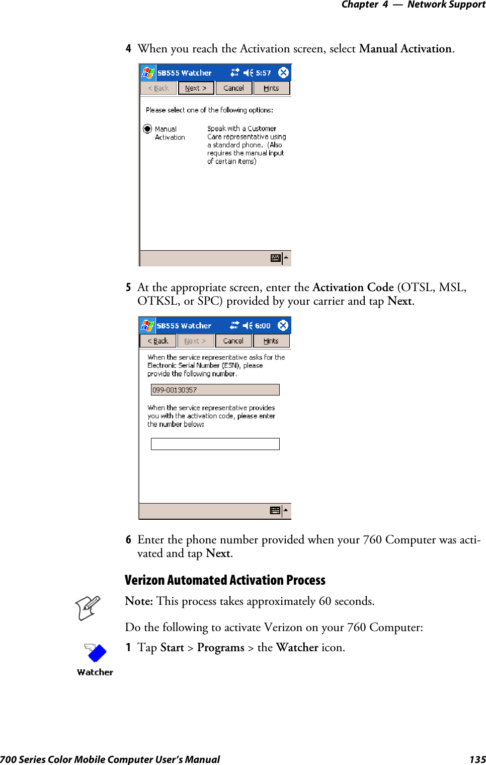
![Configurable SettingsAppendix —A234 700 Series Color Mobile Computer User’s ManualBased on your setting, do the following to “wake up” the 700 Computer:If you select:Then do this onNumeric KeyboardThen do this onAlphanumeric KeyboardMiddle Scanner Button Squeeze the button on the Scan Handle Squeeze the button on the Scan HandleLeft Scanner Button Squeeze the left scanner button Squeeze the left scanner buttonRight Scanner Button Squeeze the right scanner button Squeeze the right scanner buttonGOLD+A1(Application1) Press [Gold] ba Press [Gold/White] cAGOLD+A2(Application2) Press [Gold] b4 Press [Gold/White] cBApp LaunchFrom the 700 Color Computer, tap Start >Settings >theSystem tab >Utilities , then scroll to the right to tap the App Launch tab to access theApplication Launch applet.This applet programs or maps two scanner buttons and four applicationkeys to start up to six applications. Note the left scanner button also acts asthe record button.For 700 Color Computers with either a laser scanner or an imager,default mappings are shown in the following illustration.For 700 Color Computers without either a laser scanner or an imager,the default maps the Record, Calendar, Contacts, and Tasks applicationsthe top four and the A3 and A4 buttons are “unassigned” or available fortwo more applications.Note: Record, Calendar, Contacts, and Tasks are Pocket PC applications.See Chapter 2, “Windows Mobile 2003,” for more information.STo assign an application to a button, select an application from the ap-plicable drop-down list box.STo assign a new application, select the “Add new application” option,which brings up an Open File dialog and browse Secure Digital orCompactFlash storage cards for new applications.](https://usermanual.wiki/Intermec-Technologies/MC75.Final-Users-Manual-part-2-of-2/User-Guide-730133-Page-134.png)

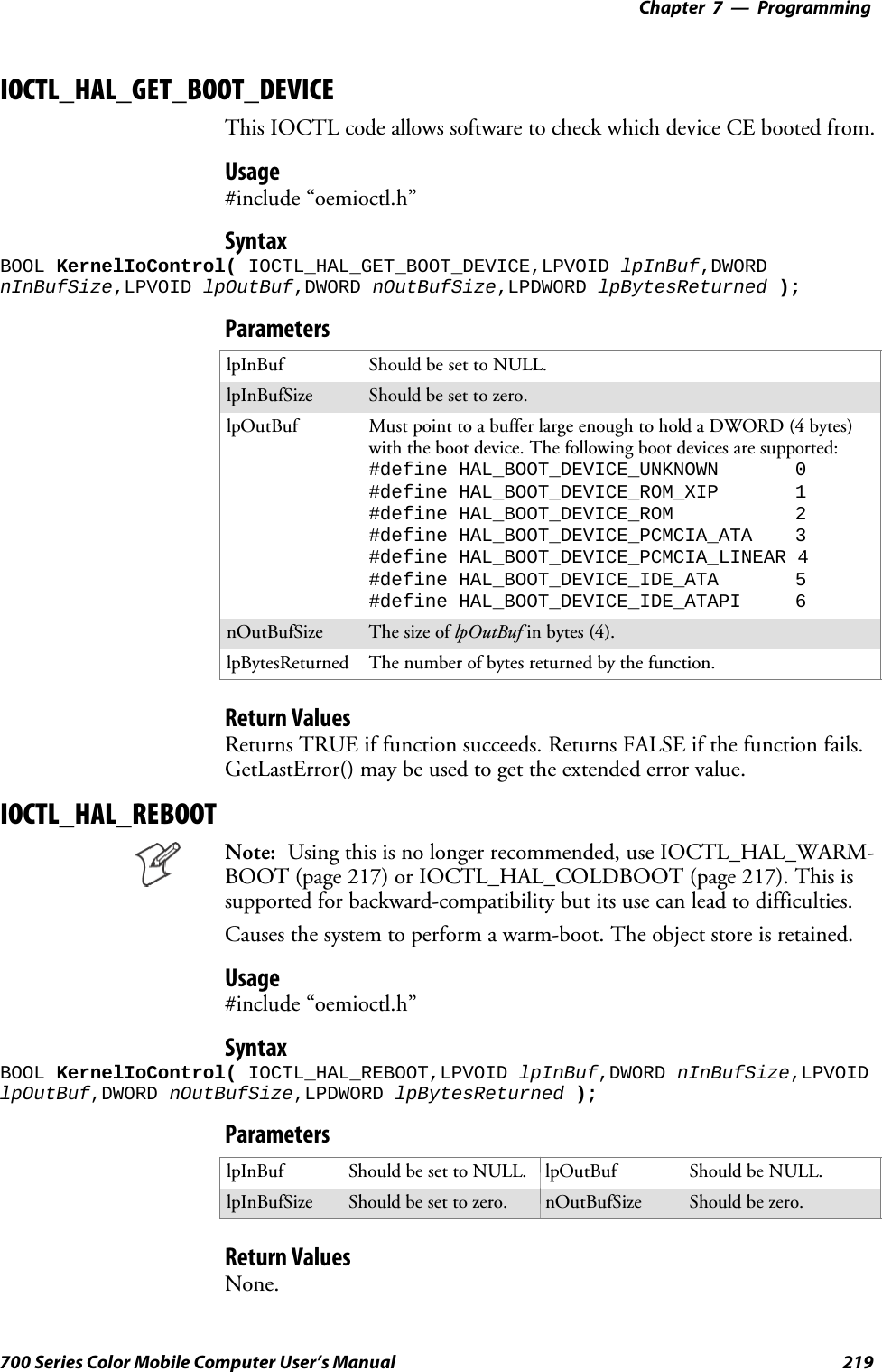
![Configurable SettingsAppendix —A254 700 Series Color Mobile Computer User’s ManualUsing Reader CommandsAfter the 700 Color Computer is connected to your network, you cansend the 700 Color Computer a reader command from an application toperform a task, such as changing the time and date. Some reader com-mands temporarily override the configuration settings and some changethe configuration settings.Change ConfigurationThe Change Configuration command must precede any configurationcommand. If you enter a valid string, the 700 Color Computer configura-tion is modified and the computer emits a high beep. To send the ChangeConfiguration command through the network, use the $+ [command]syntax where command is the two-letter command syntax for the configu-ration command followed by the value to be set for that command.You can also make changes to several different commands by using the$+ [command]...[command n] syntax. There are seven configurationcommand settings that can be changed in this way. See each command forinformation on respective acceptable “data” values.Command SyntaxAudio Volume BVdataAutomatic Shutoff EZdataBacklight Timeout DFdataKey Clicks KCdataVirtual Wedge Grid AFdataVirtual Wedge Postamble AEdataVirtual Wedge Preamble ADdataExample 1To change the Beep Volume to Off, you can send this string to the 700Color Computer through the network: $+BV0where:$+ Indicates Change Configuration.BV Specifies the Audio Volume parameter.0Specifies a value of Off.Example 2To change the Beep Volume to Very Quiet and the Virtual Wedge Gridto 123: $+BV1AF123where:$+ Indicates Change ConfigurationBV1 Specifies Audio Volume, set to Very Quiet (1)AF123 Specifies Virtual Wedge Grid, set to a value of 123.](https://usermanual.wiki/Intermec-Technologies/MC75.Final-Users-Manual-part-2-of-2/User-Guide-730133-Page-154.png)

![Index262 700 Series Color Mobile Computer User’s ManualClasses and FunctionsAadd_registry_section, [AddReg]flags, 194registry_root_string, 194value_name, 194AddReg, [DefaultInstall], 191[AddReg], add_registry_sectionflags, 194registry_root_string, 194value_name, 194AppName, [CEStrings], 189Asset management, DeviceURL parameter, 204BBlockSize, FTP Server, 204BuildMax, [CEDevice], 190BuildMin, [CEDevice], 190C[CEDevice]BuildMax, 190BuildMin, 190ProcessorType, 189UnsupportedPlatforms, 189VersionMax, 190VersionMin, 190CESelfRegister, [DefaultInstall], 191CESetupDLL, [DefaultInstall], 191CEShortcuts, [DefaultInstall], 191[CEShortcuts], shortcut_list_sectionshortcut_filename, 194shortcut_type_flag, 194target_file/path, 195target_file_path, 195CESignature[SourceDiskNames], 191[Version], 188[CEStrings]AppName, 189InstallDir, 189ClassID field valuesVN_CLASS_ASIC, 212VN_CLASS_BOOTSTRAP, 212VN_CLASS_KBD, 212CloseHandle()DTR printing, 167, 168IrDA printing, 162NPCP printing, 163, 164Cold boot, IOCTL_HAL_COLDBOOT, 217Copyfiles, [DefaultInstall], 191[CopyFiles], file_list_sectiondestination_filename, 193flags, 193source_filename, 193CreateEvent(), 225CreateFile()DTR printing, 167IrDA printing, 162NPCP printing, 163, 164D[DefaultInstall]AddReg, 191CESelfRegister, 191CESetupDLL, 191CEShortcuts, 191Copyfiles, 191DeregisterDevice(), 163DTR printing, 167[DestinationDirs], file_list_section, 192DeviceIOControl()DTR printing, 167NPCP printing, 163DeviceIoControl(), NPCP printing, 164DeviceName,FTPServer,204DeviceURL, FTP Server, 204disk_ordinal, [SourceDiskNames], 191DllRegisterServer, 191DllUnregisterServer, 191EERROR_INSUFFICIENT_BUFFERIOCTL_HAL_ITC_READ_PARM, 211IOCTL_HAL_ITC_WRITE_SYSPARM, 214ERROR_INVALID_PARAMETERIOCTL_HAL_ITC_READ_PARM, 211IOCTL_HAL_ITC_WRITE_SYSPARM, 214FFile Transfer Protocol. See FTPfile_list_section[CopyFiles]destination_filename, 193flags, 193source_filename, 193[DestinationDirs], 192filename, [SourceDiskFiles], 192FTPclient, 205configurable parameters, 204BlockSize, 204DeviceName, 204DeviceURL, 204PauseAtStartup, 205FTPDCMDS subdirectory, 208RTC 959, 208server, 205server requestsCDUP, 205CWD, 205DELE, 206HELP, 206LIST, 206MKD, 206MODE, 206NLST, 206NOOP, 206PASS, 206PWD, 206](https://usermanual.wiki/Intermec-Technologies/MC75.Final-Users-Manual-part-2-of-2/User-Guide-730133-Page-162.png)
![Index263700 Series Color Mobile Computer User’s ManualQUIT, 206RETR, 206RMD, 206RNFR, 206RNTO, 206SITE, 206SITE ATTRIB, 206SITE BOOT, 207SITE COPY, 207SITE EKEY, 207SITE EVAL, 207SITE EXIT, 207SITE GVAL, 208SITE HELP, 207SITE KILL, 207SITE LOG, 207SITE PLIST, 207SITE PVAL, 208SITE RUN, 207SITE STATUS, 207SITE TIMEOUT, 207STOR, 206SYST, 206TYPE, 206USER, 206XCUP, 206XCWD, 206XMKD, 206XPWD, 206XRMD, 206stopping server from application, 208support, 205web browsers, 208HHAL, verion of Pocket PCIOCTL_HAL_GET_BOOTLOADER_VERINFO,216IOCTL_HAL_GET_OAL_VERINFO, 216IID field valuesIOCTL_HAL_ITC_READ_PARMITC_NVPARM_80211_INSTALLED, 213ITC_NVPARM_80211_RADIOTYPE, 213ITC_NVPARM_ANTENNA_DIVERSITY, 212ITC_NVPARM_BLUETOOTH_INSTALLED,213ITC_NVPARM_CONTRAST, 212ITC_NVPARM_DISPLAY_TYPE, 212ITC_NVPARM_ECN, 212ITC_NVPARM_EDBG_SUBNET, 212ITC_NVPARM_EDG_IP, 212ITC_NVPARM_ETHERNET_ID, 212ITC_NVPARM_INTERMEC_DATACOLLEC-TION_HW, 213ITC_NVPARM_INTERMEC_DATACOLLEC-TION_SW, 212ITC_NVPARM_INTERMEC_SOFT-WARE_CONTENT, 212ITC_NVPARM_LAN9000_INSTALLED, 213ITC_NVPARM_MANF_DATE, 212ITC_NVPARM_MCODE, 212ITC_NVPARM_RTC_RESTORE, 212ITC_NVPARM_SERIAL_NUM, 212ITC_NVPARM_SERIAL2_INSTALLED, 213ITC_NVPARM_SERVICE_DATE, 212ITC_NVPARM_SIM_PRO-TECT_HW_INSTALLED, 213ITC_NVPARM_SIM_PRO-TECT_SW_INSTALLED, 213ITC_NVPARM_VERSION_NUMBER, 212ITC_NVPARM_VIBRATE_INSTALLED, 213ITC_NVPARM_WAN_FREQUENCY, 213ITC_NVPARM_WAN_INSTALLED, 213ITC_NVPARM_WAN_RADIOTYPE, 213ITC_NVPARM_WAN_RI, 212IOCTL_HAL_ITC_WRITE_SYSPARMITC_ DOCK_SWITCH, 214ITC_ WAKEUP_MASK, 215ITC_AMBIENT_FRONTLIGHT, 215ITC_AMBIENT_KEYBOARD, 215ITC_REGISTRY_SAVE_ENABLE, 214IDNADeviceName, 204DeviceURL, 204IDNATarget, FTP Server, 204InstallDir, [CEStrings], 189Intermec Device Network Announcement. See IDNAIOCTL_GET_CPU_ID, 220IOCTL_HAL_COLDBOOT, 217, 222IOCTL_HAL_GET_BOOT_DEVICE, 219IOCTL_HAL_GET_BOOTLOADER_VERINFO, 216IOCTL_HAL_GET_DEVICE_INFO, 210IOCTL_HAL_GET_DEVICEID, 215IOCTL_HAL_GET_OAL_VERINFO, 216IOCTL_HAL_GET_RESET_INFO, 218IOCTL_HAL_ITC_READ_PARM, 211IOCTL_HAL_ITC_WRITE_SYSPARM, 214IOCTL_HAL_REBOOT, 219, 222IOCTL_HAL_WARMBOOT, 217, 222IOCTL_PROCESSOR_INFORMATION, 220ITC_ DOCK_SWITCH, 214ITC_ WAKEUP_MASK, 215ITC_AMBIENT_FRONTLIGHT, 215ITC_AMBIENT_KEYBOARD, 215ITC_DEVID_80211RADIO_INTEL_2011B, 213ITC_DEVID_80211RADIO_MAX valuesITC_DEVID_80211RADIO_INTEL_2011B, 213ITC_DEVID_80211RADIO_NONE, 213ITC_DEVID_80211RADIO_NONE, 213ITC_DEVID_INTERMEC_EVIO, 213ITC_DEVID_INTERMEC2D_IMAGER, 213ITC_DEVID_OEM2D_IMAGER, 213](https://usermanual.wiki/Intermec-Technologies/MC75.Final-Users-Manual-part-2-of-2/User-Guide-730133-Page-163.png)
![Index265700 Series Color Mobile Computer User’s ManualIOCTL_HAL_WARMBOOT, 217IOCTL_PROCESSOR_INFORMATION, 220MManifestName,FTPServer,205NnDeviceId, NLEDGetDeviceInfo, 222nInBufSizeIOCTL_HAL_GET_BOOTLOADER_VERINFO,216IOCTL_HAL_ITC_READ_PARM, 211IOCTL_HAL_ITC_WRITE_SYSPARM, 214IOCTL_PROCESSOR_INFORMATION, 220nInfoId, NLEDGetDeviceInfo, 222NLED_COUNT_INFO, NLEDGetDeviceInfo, 222NLED_SETTINGS_INFO_ID, NLEDGetDeviceInfo,222NLED_SUPPORTS_INFO_ID, NLEDGetDeviceInfo,222NLEDGetDeviceInfo, 221NLEDSetDevice, 222nOutBufSizeIOCTL_GET_CPU_ID, 221IOCTL_HAL_COLDBOOT, 218IOCTL_HAL_GET_BOOT_DEVICE, 219IOCTL_HAL_GET_BOOTLOADER_VERINFO,217IOCTL_HAL_GET_DEVICE_INFO, 211IOCTL_HAL_GET_DEVICEID, 215IOCTL_HAL_GET_OAL_VERINFO, 216IOCTL_HAL_GET_RESET_INFO, 218IOCTL_HAL_ITC_READ_PARM, 211IOCTL_HAL_ITC_WRITE_SYSPARM, 214IOCTL_HAL_REBOOT, 219IOCTL_HAL_WARMBOOT, 217IOCTL_PROCESSOR_INFORMATION, 220OObject storeIOCTL_HAL_COLDBOOT, 217IOCTL_HAL_REBOOT, 219IOCTL_HAL_WARMBOOT, 217Oldstyle device ID, 215OSVERSIONINFO.dwBuildNumber, 190OSVERSIONINFO.dwVersionMajor, 190OSVERSIONINFO.dwVersionMinor, 190PPauseAtStartup, FTP Server, 205pInput, NLEDSetDevice, 222Pocket PCIOCTL_HAL_GET_BOOTLOADER_VERINFO,216IOCTL_HAL_GET_OAL_VERINFO, 216pOutput, NLEDGetDeviceInfo, 222Processor information, IOCTL_PROCESSOR_IN-FORMATION, 220ProcessorType, [CEDevice], 189Provider, [Version], 188RReadFile(), NPCP printing, 163Reboot methodsIOCTL_HAL_COLDBOOT, 222IOCTL_HAL_REBOOT, 222IOCTL_HAL_WARMBOOT, 222RegFlushKey(), 202RegisterDevice(), 163DTR printing, 167RegistryFTP Server parameters, 204save location, IOCTL_HAL_ITC_WRITE_SYSPARM,214RegOpenKeyEx(), 224RegQueryValueEx(), 224RegSetValueEx(), 224RFC 959, 208Root, FTP Server, 205SSHFullScreen(), 202shortcut_list_section, [CEShortcuts]shortcut_filename, 194shortcut_type_flag, 194target_file/path, 195target_file_path, 195Signature, [Version], 188SIM cardsprotection hardware, 213software installed, 213[SourceDiskFiles], filename, 192[SourceDiskNames]CESignature, 191disk_ordinal, 191SourceDisksNames.MIPS, 192SourceDisksNames.SH3, 192string_key, [Strings], 189[Strings], string_key, 189SYSTEMINFO.dwProcessorType, 189UUDP, FTPDCE, 205UDP broadcasts, IDNATarget parameter, 204UnsupportedPlatforms, [CEDevice], 189UUID, 215V[Version]CESignature, 188Provider, 188Signature, 188VersionMax, [CEDevice], 190VersionMin, [CEDevice], 190VN_CLASS_ASIC, 212VN_CLASS_BOOTSTRAP, 212VN_CLASS_KBD, 212](https://usermanual.wiki/Intermec-Technologies/MC75.Final-Users-Manual-part-2-of-2/User-Guide-730133-Page-165.png)
![Index267700 Series Color Mobile Computer User’s ManualGeneral IndexNumbers1551/1553 Tethered Scannerconfiguring, 177intermec settings, 177reset to factory defaults, 180troubleshooting, 1791D area imager reading distances, 1731D laser scanner, about, 1692D area imager reading distances, 1762D Imager, about, 1694820 printer, NPCP driver, 1636804DM printer, IrDA driver, 1626804T printer, IrDA driver, 1626805A printer, IrDA driver, 1626806 printer, IrDA driver, 1626808 printerIrDA driver, 162printer support, 1616820 printerIrDA driver, 162NPCP driver, 163printer support, 1616920 Communications Server, ManifestName parameter,205740 Color Computer, 223782T printer, printer support, 161802.11antenna color code, 98channel, 237communications setup, 108, 236EAP-FASTnetwork EAP, 250WPA encryption, 250LEAPnetwork EAP, 248WPA encryption, 248network type, 237PEAPnetwork EAP, 241WPA encryption, 240profile label, 237profile security information, WEP encryption, 239profiles, 237advanced settings, 252basic information, 237security information, 238SSID (network name), 237TTLS, WPA encryption, 245WPA authentication, Zero Configuration, 114WPA authentication with pre-shared key, Zero Config-uration, 114WPA encryption, 239zero configuration, WEP encryption, 113AAB10 batterylow battery conditions, 2RAM maintenance, 3status, 2Abstract Syntax Notation.1. See ASN.1Accessory list, 21Accounts, via Inbox, 66Activation wizardPhone application, CDMA radios, 122phone application, CDMA radios, 117, 119ActiveSyncActiveSync Help, 42adding programs, 38adding programs to Start menu, 40Folder behavior connected to e-mail server, 64installing applications, 87Microsoft Reader, 77Pocket Internet Explorerfavorite links, 80mobile favorites, 80Mobile Favorites folder, 80replicating registry settings, 89Start menu icon, 27URL, 41Windows Mobile, 41Adding bookmarks, Microsoft Reader, 79Adding drawings to text, Microsoft Reader, 79Adding programsActiveSync, 38Pocket Internet Explorer, 40to the Start menu, 40via ActiveSync, 40via File Explorer, 40Windows Mobile, 38Adjusting settings, Windows Mobile, 38Adobe Acrobat Reader, URL, 144All-Day events, Calendar, 44creating, 48Alpha plane on keypad, 224Alphanumeric keypadalpha (blue) key sequences, 13[gold/white] key sequences, 12registry settingsalpha plane, 224gold plane, 224unshifted plane, 224scan codes, 227Ambient lighting, 4Annotations index, Microsoft Reader, 79Antenna, radio type, 98APIsAT command interface, 143IrSock, 162network selection, 221App launch, utilities applet, 234](https://usermanual.wiki/Intermec-Technologies/MC75.Final-Users-Manual-part-2-of-2/User-Guide-730133-Page-167.png)
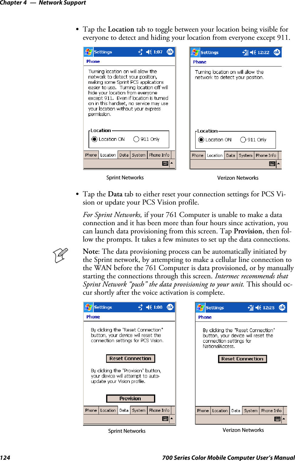
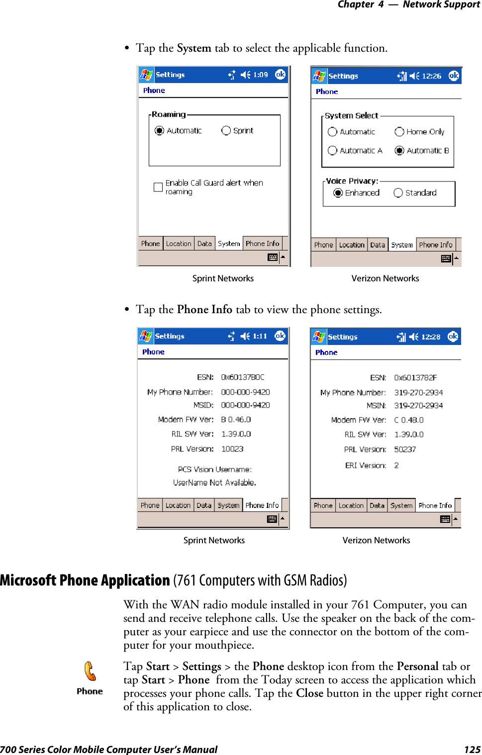
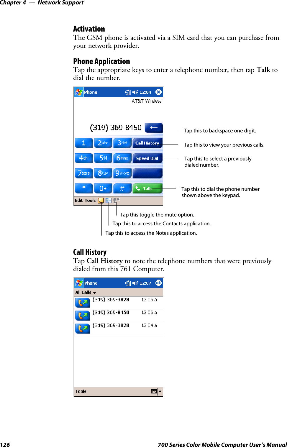
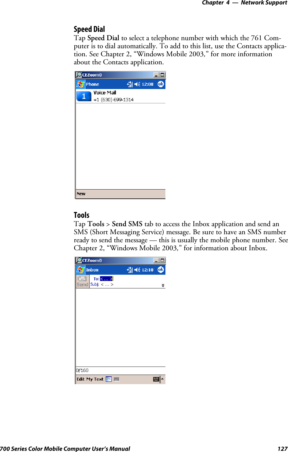
![Index272 700 Series Color Mobile Computer User’s ManualIrDA printing, 162ISPconnecting to via Windows Mobile, 148creating, a modem connection, 148Pocket Internet Explorer, 79Windows Mobile, 148ITC_KEYBOARD_CHANGE, CreateEvent(), 225ITU-T interface specifications, 143KKeeping a to-do list, via Tasks, 60Key clicksbar code configuration, 253, 257configuration parameter, 253Key sequencesalpha (blue) keysalphanumeric, 13numeric, 12[gold]keys,numeric,11[gold/white] keys, alphanumeric, 12KeyboardSee also KeypadWindows Mobile input panel, 30Keypadadvanced remapping, 225alphanumericalpha (blue) key sequences, 13[gold/white] key sequences, 12scan codes, 227backlight applet, 10change notification, 225driver registry settings, 224numericalpha (blue) key sequences, 12[gold] key sequences, 11scan codes, 226planes, 223remapping, 223sample registry keys, 228specifications, 22LLaser scanner, configuration parameters, 230LEAP802.11 radio modulenetwork EAP, 248WPA encryption, 248profile security information, 247WEP encryption, 247LED status, 14battery, 14scanning keypad/shift and notification, 15Letter recognizer, Windows Mobile input panel, 32Letting your location be visible, CDMA radios, 124Library, Microsoft Reader, 78Line printing, 162Location, Phone application, CDMA radios, 124LPT9 printer device, 163MManaging e-mail messages and folders, via Inbox, 64MC75 radio radome, 99MeetingsCalendar, sending a request, 51via Calendar, 42Memory and storage, specifications, 22Menus, Windows Mobile settings, 38Messagessending to, contacts, 58via Inboxcomposing/sending, 66downloading from server, 66MIBsASN.1, 157files, 157object identifier, 158Micro Electro Mechanical System (MEMS), 169Microphone, 5Microprocessor, specifications, 22Microsoft Developer Network Library. See MSDN libraryMicrosoft Exchange e-mail account, 73Microsoft Passport account, 73Microsoft Readerbooksdownloading, 77reading, 78removing, 79features, 79adding bookmarks, 79adding drawings, 79annotations index, 79attaching notes, 79copying text, 79highlighting text, 79searching for text, 79using the library, 78Windows Mobile, 77Microsoft’s Wireless Zero Config, 237Migrating to a 700 Color Computer, 95Mobile Favorites, Pocket Internet Explorer, 80Mobile Favorites folder, Pocket Internet Explorer, 80Modem position, COM A, 232Modemscreating a connectionto an ISP, 148to work, 152specifications, 22MP3 files, Windows Media Player, 77MSDN library, 209MSDN Windows CE documentation, 116](https://usermanual.wiki/Intermec-Technologies/MC75.Final-Users-Manual-part-2-of-2/User-Guide-730133-Page-172.png)
![Index273700 Series Color Mobile Computer User’s ManualMSN MessengeraccountsMicrosoft Exchange e-mail, 73Microsoft Passport, 73contactsmanaging, 75sending messages, 76working with, 75setting up an account, 74using My Text, 36MultiMediaCards, card support, 18NNetwork adaptersantenna color code, 98Ethernet communications, 109no networking, 110wireless 802.11, 110wireless printing, 99Network EAPEAP-FAST security method, 250LEAP security method, 248PEAP security method, 241Network selection APIs, 221Network settings, Phone application, GSM radios, 129Network type, 802.11 radio module, 237NLED driver, vibrator, 221NLED_SETTINGS_INFO_ID, NLEDSetDevice, 222Notesadding toappointments, 49contacts, 56creating a note, 62drawing on the screen, 35creating a drawing, 35selecting a drawing, 35Pocket Outlook, 62recording a message, 36Start menu icon, 28synchronizing notes, 63writing on the screen, 32alternate writing, 34converting writing to text, 33selecting the writing, 33tips for good recognition, 34NPCP printing, 163about, 163closing driver, 164COM1 parameters, 163communications, 165driver I/O controls, 164installation, 163LPT9, 163opening driver, 164reading from driver, 164removal, 163sample code, 166writing to driver, 164Numeric keypadalpha (blue) key sequences, 12[gold] key sequences, 11registry settingsalpha plane, 224gold plane, 224unshifted plane, 224scan codes, 226OO’Neil printingSee also DTR printerinstalling driver, 167Object Store, packaging an application, 86Opening driversDTR, 167NPCP, 164Operating system, specifications, 23Owner information, Windows Mobile settings, 38PPackaging an applicationCompactFlash storage cards, 86FlashFileStore,86Object Store, 86Persistent Storage Manager, 86Secure Digital storage cards, 86Page format printing, 162PasswordPocket Excel, 72Windows Mobile settings, 38Patent information, xviiPB20 printers, printer support, 161PB42 printersintermec settings applet, 168printer support, 161PDF417, about the laser scanner, 169PEAP802.11 radio modulenetwork EAP, 241WPA encryption, 240profile security information, 240WEP encryption, 240Performing a cold boot, 16Performing a warm boot, 16Persistent Storage Manager. See PSMPhone applicationCDMA radios, 117activation wizard, 117, 119, 122adding contact to speed dial, 59, 121call history, 122customizing phone settings, 123enable Call Guard alert while roaming, 125hiding your location except from 911, 124letting your location be visible for everyone, 124reset connection settings for PCS Vision, 124sending SMS messages, 123toggle between automatic or Sprint roaming, 125update your PCS Vision profile, 124view current phone settings, 125voice mail, 122](https://usermanual.wiki/Intermec-Technologies/MC75.Final-Users-Manual-part-2-of-2/User-Guide-730133-Page-173.png)