Intermec Technologies NOVCDPD Mobile Computer with WAN CDPD radio User Manual 020117A1
Intermec Technologies Corporation Mobile Computer with WAN CDPD radio 020117A1
Contents
- 1. App F User Info Declaration and Warnings
- 2. Novatel User Manual
- 3. 20020117 app A user manual
20020117 app A user manual

Intermec Technologies Corporation FCC ID: EHANOVCDPD
EMC Test Lab REPORT NO: 20020117-1
DOC. NO.: 577-501-008 Page 1 of 18
700 CDPD, FCC 2.1053 Radiated Spurious Emissions, Appendix A
Technologies Corporation
EMC Test Laboratory
Cedar Rapids, IA
MEASUREMENT/TECHNICAL REPORT
Intermec Technologies Corporation
700 With Novatel CDPD
Cellular Radio Module
REPORT NO: 20020117-1
DATE: January 17, 2002
APPENDIX A
NOVATEL USERS MANUAL

NOVATEL WIRELESS
TECHNOLOGIES LTD.
Calgary, Alberta
TITLE: Hardware Interface Specification for
Expedite Wireless IP Modem
DOCUMENT NO.:
OM-01016529 SHEET:
1 of 17 REV: 3.0
EXPEDITE
WIRELESS IP MODEM
HARDWARE INTERFACE
SPECIFICATION
OM - 01016529
Revision 3

NOVATEL WIRELESS
TECHNOLOGIES LTD.
Calgary, Alberta
TITLE: Hardware Interface Specification for
Expedite Wireless IP Modem
DOCUMENT NO.:
OM-01016529 SHEET:
2 of 17 REV: 3.0
REVISION HISTORY
REV#
ECO# EFF. DATE
DESCRIPTION PREPARED APPROVED
1 99007 Initial release. P. Faubert S. Smilar
2 99024 990709 Change order of pins 21 and 22 P. Faubert S. Smilar
3 99047 990809 Add mounting instructions K. Frayn S. Smilar

NOVATEL WIRELESS
TECHNOLOGIES LTD.
Calgary, Alberta
TITLE: Hardware Interface Specification for
Expedite Wireless IP Modem
DOCUMENT NO.:
OM-01016529 SHEET:
3 of 17 REV: 3.0
The information disclosed herein is the exclusive property of NOVATEL WIRELESS TECHNOLOGIES
LTD. and is not to be disclosed without the written consent of NOVATEL WIRELESS TECHNOLOGIES
LTD. No part of this publication may be reproduced or transmitted in any form or by any means including
electronic storage, reproduction, execution or transmission without the prior written consent of NOVATEL
WIRELESS TECHNOLOGIES LTD. The recipient of this document by its retention and use, agrees to
respect the security status of the information contained herein.
The information disclosed herein is the exclusive property of Novatel Wireless Technologies Ltd. and is
not to be disclosed without the written consent of Novatel Wireless Technologies Ltd. No part of this
publication may be reproduced or transmitted in any form or by any means including electronic storage,
reproduction, execution or transmission without the prior written consent of Novatel Wireless
Technologies Ltd. The recipient of this document by its retention and use, agrees to respect the security
status of the information contained herein.
This document is intended for limited circulation.
The information contained in this document is subject to change without notice and should not be
construed as a commitment by NOVATEL WIRELESS TECHNOLOGIES LTD. unless such commitment
is expressly given in a covering document.
© Copyright NOVATEL WIRELESS TECHNOLOGIES LTD. (1999)

NOVATEL WIRELESS
TECHNOLOGIES LTD.
Calgary, Alberta
TITLE: Hardware Interface Specification for
Expedite Wireless IP Modem
DOCUMENT NO.:
OM-01016529 SHEET:
4 of 17 REV: 3.0
Table of Contents
1 WARNING........................................................................................................................................6
2 INTRODUCTION..............................................................................................................................6
3 SCOPE.............................................................................................................................................6
4 SPECIFICATIONS ...........................................................................................................................6
4.1 Physical Interface ......................................................................................................................6
4.1.1 Data/Power Connection ......................................................................................................7
4.1.2 RF Antenna Connector Type...............................................................................................8
4.1.3 Pin Descriptions..................................................................................................................9
4.2 Host Interface Specifications ...................................................................................................10
4.2.1 Serial Data Rate and Format ............................................................................................10
4.3 Radio Specifications ................................................................................................................10
4.3.1 Airlink Data Rate...............................................................................................................10
4.3.2 Recommended Antenna Type...........................................................................................10
4.3.3 Frequency Range .............................................................................................................10
4.3.4 Duplex Mode ....................................................................................................................10
4.3.5 RF Power Class................................................................................................................10
4.4 Electrical Specifications...........................................................................................................11
4.5 Mechanical Specifications........................................................................................................12
4.5.1 Dimensions.......................................................................................................................12
4.5.2 Weight..............................................................................................................................12
4.6 Environmental Specifications...................................................................................................12
4.6.1 Temperature Range..........................................................................................................12
4.6.2 Humidity ...........................................................................................................................12
4.6.3 ...............................................................................................................................................12
4.6.4 Shock Stability..................................................................................................................13
4.6.5 Vibration Stability..............................................................................................................13
4.6.6 Regulatory compliance .....................................................................................................13
4.6.7 ESD Protection.................................................................................................................13
4.7 CDPD Part 409 Compliance ....................................................................................................14
5 INSTALLATION INSTRUCTIONS..................................................................................................15
5.1 Antenna Mounting....................................................................................................................15
5.2 Antenna...................................................................................................................................15
5.3 Labeling...................................................................................................................................15
5.4 User Manual ............................................................................................................................15
6 PACKAGING REQUIREMENTS ....................................................................................................17

NOVATEL WIRELESS
TECHNOLOGIES LTD.
Calgary, Alberta
TITLE: Hardware Interface Specification for
Expedite Wireless IP Modem
DOCUMENT NO.:
OM-01016529 SHEET:
5 of 17 REV: 3.0
6.1 Shipping Packaging.................................................................................................................17
6.2 Labeling...................................................................................................................................17

NOVATEL WIRELESS
TECHNOLOGIES LTD.
Calgary, Alberta
TITLE: Hardware Interface Specification for
Expedite Wireless IP Modem
DOCUMENT NO.:
OM-01016529 SHEET:
6 of 17 REV: 3.0
1 WARNING
All persons must be at least 20 cm from the antenna when transmitter operating to meet FCC RF
exposure requirements. Refer to the Installation Instructions section for specific requirements for the
antenna used with module.
2 INTRODUCTION
This document describes the hardware interface for the Novatel Wireless Expedite Wireless IP Modem.
The Expedite Wireless IP Modem is an OEM module designed for integration into a host product to
provide two-way wireless data communication capability via the CDPD (Cellular Digital Packet Data)
Network.
3 SCOPE
The scope of this document includes all pertinent information for describing the capabilities and
operating requirements for the product in order to determine suitability for specific market applications.
Internal design issues, detailed operating instructions and cost information is not included in this
document.
4 SPECIFICATIONS
4.1 Physical Interface
NOVATEL WIRELESS
TECHNOLOGIES LTD.
Calgary, Alberta
TITLE: Hardware Interface Specification for
Expedite Wireless IP Modem
DOCUMENT NO.:
OM-01016529 SHEET:
7 of 17 REV: 3.0
4.1.1 Data/Power Connection
One connector is used to physically connect the power supply and 3.3 volt logic level host
communication interface signals to the Expedite Wireless IP Modem.
4.1.1.1 Data/Power Connector Type
Description: 24-pin, 1.27 mm pitch, SMT, double row low profile socket type
Samtec part number: CLP-112-02-F-D
Some interface connector options are provided here for reference. Contact Samtec for the latest
connector mating options.

NOVATEL WIRELESS
TECHNOLOGIES LTD.
Calgary, Alberta
TITLE: Hardware Interface Specification for
Expedite Wireless IP Modem
DOCUMENT NO.:
OM-01016529 SHEET:
8 of 17 REV: 3.0
4.1.1.2 Surface Mount Mating Connector Options
Description: 24-pin, 1.27 mm pitch, SMT, double row, zero profile, pin type header
Samtec part number: DIS5-112-52-F-D-VS
NOTE: This connector provides the lowest profile interface solution.
Description: 24-pin, 1.27 mm pitch, SMT, double row, low profile, pin type header
Samtec part number: FTS-112-03-F-DV
4.1.1.3 Through-Hole Mating Connector Options
Description: 24-pin, 1.27 mm pitch, T/H, double row, zero profile, pin type header
Samtec part number: DIS5-112-52-F-D
Description: 24-pin, 1.27 mm pitch, T/H, double row, low profile, pin type header
Samtec part number: FTS-112-03-F-D
4.1.2 RF Antenna Connector Type
Expedite Wireless IP Modem antenna connector:
Description - MMCX Coaxial Connector
Manufacturer - Huber and Suhner
Part Number - 82MMCX-S50-0-2
NOTE: An equivalent connector by the same or another manufacturer may be used.
Impedance - 50 ohm
Expedite Wireless IP Modem mating antenna connector:
Mating connector: - AEP 8905-1521-003 or equivalent with RG316 cable.

NOVATEL WIRELESS
TECHNOLOGIES LTD.
Calgary, Alberta
TITLE: Hardware Interface Specification for
Expedite Wireless IP Modem
DOCUMENT NO.:
OM-01016529 SHEET:
9 of 17 REV: 3.0
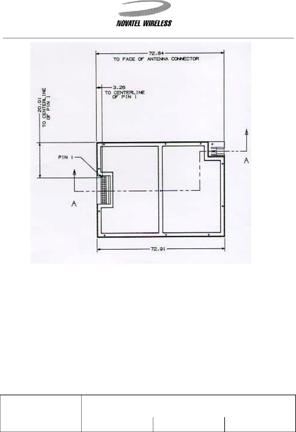
4.1.3 Pin Descriptions
Pin # Name Direction Power-on
Reset State Description
13, 14 Vcc1 POWER POWER SUPPLY CONNECTION TO THE MODEM FOR ALL
CIRCUITRY EXCEPT FOR THE RF POWER AMPLIFIER.
15, 16 Vcc2 POWER POWER SUPPLY CONNECTION TO THE MODEM FOR THE RF
POWER AMPLIFIER ONLY
1,2 &
23,24 GND POWER MODEM GROUND
3 PWR_IND OUTPUT POWER INDICATOR:
HI: INDICATES THAT THE MODEM IS ON
LO INDICATES THAT THE MODEM IS OFF
5 SM_IND OUTPUT SLEEP MODE INDICATOR:
HI: INDICATES THAT THE MODEM IS IN SLEEP MODE
LO INDICATES THAT THE MODEM IS NOT IN SLEEP MODE
4 WKUP INPUT WAKE UP INPUT: (ACTIVE HI PULSE)
A PULSE APPLIED TO THIS PIN WILL TURN ON THE MODEM IF
THE MODEM IS OFF, OR WAKE UP THE MODEM IF THE MODEM IS
IN SLEEP MODE. REFER TO THE APPLICATIONS INFORMATION
SECTION FOR MORE DETAILS ON USING THE WAKE UP PIN.
6 DTM INPUT DATA TO MODEM:
(3.3 VOLT LOGIC LEVEL)
IN RS232 TERMS, THIS IS CALLED "TXD".
7 DFM OUTPUT DATA FROM MODEM:
(3.3 VOLT LOGIC LEVEL)
IN RS232 TERMS, THIS IS CALLED "RXD".
11 RTS INPUT READY TO SEND:
(3.3 VOLT LOGIC LEVEL)
10 CTS OUTPUT CLEAR TO SEND:
(3.3 VOLT LOGIC LEVEL)
8 DTR INPUT DTE READY:
(3.3 VOLT LOGIC LEVEL)
9 DSR OUTPUT DCE READY:
(3.3 VOLT LOGIC LEVEL)
12 GPIO1 BI-
DIRECTIONAL INPUT WITH
PULLUP GENERAL PURPOSE CONFIGURABLE INPUT OR OUTPUT:
REFER TO THE AT COMMAND SET FOR THE DEFAULT STATE.
17 GPIO2 BI-
DIRECTIONAL INPUT WITH
PULLUP GENERAL PURPOSE CONFIGURABLE INPUT OR OUTPUT:
REFER TO THE AT COMMAND SET FOR THE DEFAULT STATE.
18 GPIO3 BI-
DIRECTIONAL INPUT WITH
PULLDOWN GENERAL PURPOSE CONFIGURABLE INPUT OR OUTPUT:
REFER TO THE AT COMMAND SET FOR THE DEFAULT STATE.
19 GPIO4 BI-
DIRECTIONAL INPUT WITH
PULLUP GENERAL PURPOSE CONFIGURABLE INPUT OR OUTPUT:
REFER TO THE AT COMMAND SET FOR THE DEFAULT STATE.
20 GPIO5 BI-
DIRECTIONAL INPUT WITH
PULLDOWN GENERAL PURPOSE CONFIGURABLE INPUT OR OUTPUT:
REFER TO THE AT COMMAND SET FOR THE DEFAULT STATE.
21 GPIO6 BI-
DIRECTIONAL INPUT WITH
PULLUP GENERAL PURPOSE CONFIGURABLE INPUT OR OUTPUT:
REFER TO THE AT COMMAND SET FOR THE DEFAULT STATE.
22 ADC_IN ANALOG
INPUT ADC INPUT ADC INPUT:
THIS PIN IS CONNECTED TO ONE CHANNEL OF AN 8-BIT ADC.
REFER TO THE AT COMMAND SET ON HOW TO READ THIS ADC
VALUE.

NOVATEL WIRELESS
TECHNOLOGIES LTD.
Calgary, Alberta
TITLE: Hardware Interface Specification for
Expedite Wireless IP Modem
DOCUMENT NO.:
OM-01016529 SHEET:
10 of 17 REV: 3.0
4.2 Host Interface Specifications
4.2.1 Serial Data Rate and Format
The Expedite supports asynchronous data transmission of the following rate and format:
Baud Rate (bits/second) 1200, 2400, 4800, 9600, 19200, 38400
Data bits 7, 8
Parity Even, None, Odd Mark
Stop Bits
1, 2
4.3 Radio Specifications
4.3.1 Airlink Data Rate
Rate - 19200 bits per second
Error correction - Reed Solomon (63,47)
Transmission standard (CDPD System Specification Part 401, Section 4.5.)
4.3.2 Recommended Antenna Type
Type - Half-Wave Dipole
Impedance - 50 ohm nominal
VSWR - 1.5:1 nominal, 2.0:1 maximum
Note that the module is aligned assuming a 1.2 dB antenna gain (cable loss included in antenna gain).
4.3.3 Frequency Range
Mode Frequency Range
Transmit 824 MHz - 849 MHz
Receive 869 MHz - 894 MHz
4.3.4 Duplex Mode
Full-Duplex
(CDPD System Specification Version 1.1 part 409, paragraph 4.2)
4.3.5 RF Power Class
Class III (0.6 Watt ERP)

NOVATEL WIRELESS
TECHNOLOGIES LTD.
Calgary, Alberta
TITLE: Hardware Interface Specification for
Expedite Wireless IP Modem
DOCUMENT NO.:
OM-01016529 SHEET:
11 of 17 REV: 3.0
(CDPD System Specification Version 1.1 part 409, paragraph 4.3)
4.4 Electrical Specifications
4.4.1.1 Operating Characteristics (Ta = 0ºC to 60ºC, VCC1 & VCC2 = 3.6V, unless
otherwise noted.)
SYMBOL PARAMETER / CONDITIONS MIN TYPICAL MAX UNITS
VCC1 MODEM SUPPLY VOLTAGE 3.45 3.6 4.5 V
VCC2 RF POWER AMPLIFIER SUPPLY VOLTAGE 3.45 3.6 4.5 V
MODEM OFF
VCC1 = 3.6V 5 µA
SLEEP MODE
VCC1 = 3.6V 8 mA
RECEIVE MODE
VCC1 = 3.6V 130
mA
ICC1
TRANSMIT MODE
VCC1 = 3.6V 175 mA
MODEM OFF
VCC2 = 3.6V 5 µA
SLEEP MODE
VCC2 = 3.6V 5 µA
RECEIVE MODE
VCC2 = 3.6V 5 µA
ICC2
TRANSMIT MODE
VCC2 = 3.6V 50 725 mA
TWAKEUP WAKE-UP PULSE WIDTH
FROM SLEEPMODE
FROM POWER UP
10
500
mSec
VIL1(NOTE 1) INPUT VOLTAGE – LOW (EXCEPT FOR WKUP)
MODEM ON
MODEM OFF
-0.5
0
0.8
0
V
VIH1(NOTE 1) INPUT VOLTAGE - HIGH (EXCEPT FOR WKUP)
MODEM ON
MODEM OFF
2.0
3.3
3.7
0.0
V
VIL2(NOTE 2) INPUT VOLTAGE - LOW (WKUP ONLY) WKUP ONLY -0.5 0 0.5 V
VIH2(NOTE 2) INPUT VOLTAGE - HIGH (WKUP ONLY) 3.0 4.5 V
VOL(NOTE 1) OUTPUT VOLTAGE - LOW (IOL = 1.0mA) 0.78 V
VOH(NOTE 1) OUTPUT VOLTAGE - HIGH (IOH = -200µA) 2.6 3.3 3.4 V
IOL(NOTE 1) MAXIMUM SINK CURRENT -1.0 mA
IOH(NOTE 1) MAXIMUM SOURCE CURRENT 1.0 mA
VADC ADC INPUT VOLTAGE
ADC READABLE VOLTAGE RANGE
ABSOLUTE MAXIMUM INPUT VOLTAGE
1.5
5.50
8.50
V
RESADC ADC RESOLUTION 8 BITS
24 mV
REFADC ADC REFERENCE VOLTAGE 2.048 V
DIVADC ADC DIVIDER RATIO 1:3
ZADC ADC INPUT IMPEDANCE 300k OHMS
NOTE 1 - The specifications apply to all pins on the serial interface connector except for the following pins: GND, VCC1, VCC2 &
ADC_IN. All pins have except VCC1, VCC2 and GND are filtered via a 470pF shunt capacitor and a 330 ohm series resistor which
affects the sink and source capability of the pin.

NOVATEL WIRELESS
TECHNOLOGIES LTD.
Calgary, Alberta
TITLE: Hardware Interface Specification for
Expedite Wireless IP Modem
DOCUMENT NO.:
OM-01016529 SHEET:
12 of 17 REV: 3.0
NOTE 2 - The WKUP pin is not connected directly to the CPU, it is connected though a resistor to the base of an NPN transistor.
4.5 Mechanical Specifications
4.5.1 Dimensions
5.00 mm x 54.00 mm x 72.91 mm
4.5.2 Weight
Approximately: 27g
4.6 Environmental Specifications
4.6.1 Temperature Range
The temperature is defined as per the CDPD System Specification Version 1.1 part 409,
paragraph 5.2.1
Mode Lower Limit Upper Limit
Operating (Compliant) 0 Degrees C +60 Degrees C
Operating (De-rated) -20 Degrees C +60 Degrees C
Storage -40 Degrees C +85 Degrees C
4.6.2 Humidity
CDPD Part 409 paragraph 5.2.2
50 degrees C
40% RH
8 hours

NOVATEL WIRELESS
TECHNOLOGIES LTD.
Calgary, Alberta
TITLE: Hardware Interface Specification for
Expedite Wireless IP Modem
DOCUMENT NO.:
OM-01016529 SHEET:
13 of 17 REV: 3.0
4.6.3 Shock Stability
CDPD Part 409 paragraph 5.2.3.1
Half sine wave, 20g peak acceleration, 7 to 11 ms
3 impact on each of 6 faces
4.6.4 Vibration Stability
CDPD Part 409 par. 5.2.3.2 (non-operational)
Sinusoidal vibration at 1.5g acceleration swept through 5Hz to 500Hz, 0.1 octave/second
4.6.5 Regulatory compliance
FCC title 47, parts 15 (class B) and 22. Resubmission is not required for the changes made in
this product, including the changes made to name and part number.
4.6.6 ESD Protection
No ESD protection is provided for the Expedite Wireless IP Modem. Expedite is intended to be
used in an OEM application. It is the responsibility of the OEM manufacturer to provide the
necessary ESD protection for their application.

NOVATEL WIRELESS
TECHNOLOGIES LTD.
Calgary, Alberta
TITLE: Hardware Interface Specification for
Expedite Wireless IP Modem
DOCUMENT NO.:
OM-01016529 SHEET:
14 of 17 REV: 3.0
4.7 CDPD Part 409 Compliance
The module will meet the CDPD System Specification Part 409, Small Form-Factor Devices.
CDPD
Part 409 Specification Parameter Condition Upper Limit Lower limit
7.1.2.2 RX sensitivity in AWGN
(Note a: small form factor M-ES) less than 5% block
error rate -111 dBm
7.1.2.3 RX sensitivity in Raleigh fading
(Note b: small form factor M-ES) -8 km/hr, 1% ber
-50 km/hr, 1% ber
-100 km/hr, 1% ber
-98 dBm
-100 dBm
-101 dBm
7.2.3 Co-channel interference rejection
and delay 8 us delay 17 dB rejection
7.3.3 Adjacent/Alternate channel
selectivity +/-30 kHz from carrier
+/-60 kHz from carrier 16 dB
60 dB
7.4.3 Intermodulation spurious
response 57 dB
7.5.3 RSSI + 6 dB absolute
+ 3 dB relative - 6 dB absolute
- 3 dB relative
7.6.1.2 Radiated spurious emissions 25 - 70 MHz
70 - 130 MHz
130 - 174 MHz
174 - 260 MHz
260 - 470 MHz
470 - 1000 MHz
-45 dBm
-41 dBm
-41 to -32 dBm
-32 dBm
-32 to -26 dBm
-21 dBm
7.6.2.2 Conducted spurious emissions 450 kHz - 2600 MHz
869.01 - 893.07 MHz
824.01 - 848.97 MHz
-47 dBm
-80 dBm
-60 dBm
8.1.3 Frequency stability +2.5 PPM - 2.5 PPM
8.2.3 Phase noise 1 kHz
10 kHz -55 dBc/Hz
-75 dBc/Hz
8.3.3 Emission spectrum adjacent channel
alternate channel
second alternate
channel
-26 dBc
-45 dBc
-60 dBc / –
23dBm
(whichever is
lower)
8.4.3 Channel switching time 40 ms
8.5.3.3 Power stability (PA power levels) +2 dBm -4 dBm
8.5.4.3 Switching time requirements – on
to off 2 ms
8.5.5.3 Release time requirements 2 ms
8.6.1.3 Modulation type 0.5 + 5%
19.2kbps +
50ppm
0.5 – 5%
19.2kbps – 50ppm
8.7.1.3 Radiated harmonic and spurious
emissions 43 + 10 log(mean
output power in
Watts) dB
8.7.2.3 Conducted harmonic and
spurious emissions 43 + 10 log(mean
output power in
NOVATEL WIRELESS
TECHNOLOGIES LTD.
Calgary, Alberta
TITLE: Hardware Interface Specification for
Expedite Wireless IP Modem
DOCUMENT NO.:
OM-01016529 SHEET:
15 of 17 REV: 3.0
CDPD
Part 409 Specification Parameter Condition Upper Limit Lower limit
Watts) dB
5 INSTALLATION INSTRUCTIONS
Unless the final product satisfies SAR (Specific Absorption Ratio) compliance through separate FCC
approval, integration of this module into other products has some requirements which are outlined below.
5.1 Antenna Mounting
The antenna must be mounted at a location such that no person(s) can come closer than 20 cm (7.9
inches) to the antenna when the transmitter is operating.
5.2 Antenna
This module is limited to operate with an antenna with maximum of 2.15 dBi nominal gain or not to
exceed 1.5 Watts ERP for any type of remotely mounted outdoor external antenna.
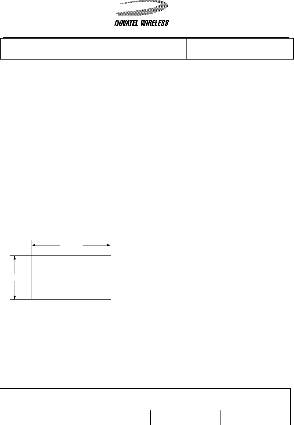
5.3 Labeling
The following label, visible to all persons exposed to the transmitter, must be provided on the end
product unless SAR compliance can be demonstrated:
5.4 User Manual
You must also provide the above warning in the user manual for the end product and also include the
following:
Do not substitute any antenna for the one supplied by the manufacturer. You may be exposing
person(s) to harmful radiation. contact the supplier or manufacturer for further instruction.
Warning
:
All persons must
be at least 20 cm from
antenna when transmitter
operating to meet FCC RF
exposure requirements
46.00mm.
25.40mm.

NOVATEL WIRELESS
TECHNOLOGIES LTD.
Calgary, Alberta
TITLE: Hardware Interface Specification for
Expedite Wireless IP Modem
DOCUMENT NO.:
OM-01016529 SHEET:
16 of 17 REV: 3.0
5.5 Mounting
Several methods are available for mounting the Expedite modem. The simplest for space constrained
applications is a pressure fit. For applications where vibration is not an issue, double sided adhesive
works well, although makes disassembly difficult. For applications where vibration is a concern, two
mounting straps are available, a surface mount soldered version (Novatel part number 649496 00233 6)
and a through – hole soldered version ( Novatel part number 649496 00232 9).

NOVATEL WIRELESS
TECHNOLOGIES LTD.
Calgary, Alberta
TITLE: Hardware Interface Specification for
Expedite Wireless IP Modem
DOCUMENT NO.:
OM-01016529 SHEET:
17 of 17 REV: 3.0
6 PACKAGING REQUIREMENTS
6.1 Shipping Packaging
Packaging shall be appropriate for the shipping method.
If the modem is to leave the ESD controlled environment, it should be packaged in an antistatic
bag.
6.2 Labeling
The modem labeling shall include:
Product Label with FCC ID, country of origin, serial number, part number, and FCC compliance
statement.