Intermec Technologies RFID915IM5 Intellitag RFID Radio User Manual IM5 Module QSG
Intermec Technologies Corporation Intellitag RFID Radio IM5 Module QSG
Contents
- 1. Users Manual Part I
- 2. Users Manual Part II
- 3. Users Manual
Users Manual
Installation and
IM5 Reader
Module
Quick Start Guide

2 IM5 Reader Module Installation and Quick Start Guide
Packing List
Checktoensurethatyoureceivetheseitems:
SIntermecRIM5 Reader Module
SCompliance Statement
SWarranty Card
The IM5 RFID module is EPCglobal Gen2 certified
(86x MHz RFID frequency band).
The IM5 RFID module is EPCglobal Gen2 certified
(915 MHz RFID frequency band).
Host Communication
Host communication comes through the 9-pin female D-sub
connector. RS-232 standards are supported as ordered from the
factory or service center.
SThe maximum data rate is 115.2K baud, with 8 data bits, no
parity bit, and 1 stop bit.
SThe maximum RS-232 distance from the reader to the host,
modem, or other physical controller interface is 50 feet (15.2
meters).
RS-232 Connections
Pin Number Definition
2TXD (Transmit Data) to the host
3RXD (Receive Data) from the host
5Ground
7CTS (Clear to Send) from the host
8RTS (Request to Send) to the host

3
IM5 Reader Module Installat ion and Quick Start Guide
Power Requirements
Power comes in from 8 to 10 volts DC. Your 915 MHz Reader
uses less than 2.4 amps. Intermec supplies 9 volts DC at 2.4
amps from Intermec power supply, p/n: 851-067-001.
User I/O
A general purpose I/O (Input/Output) connector provides sig-
nal lines in and out of the reader allowing monitoring and/or
control of external devices or functions.
Theconnectorforthisisa13-pinfemalecircularDIN.The
mating male connector you need for mating with this is an In-
termec p/n: 351-184-001.
I/O Pin-outs
Pin Number Definition
1GPIO IN0
2GPIO IN1
3GPIO IN2
4GPIO IN3
5GPIO OUT0
6GPIO OUT1
7GPIO OUT2
8GPIO OUT3
9 through 13 Ground through individual 10 ohm
resistors
Outputs and inputs have 12 volt transient suppression devices
to ground at the connector. Output signals are driven by
2N3904 NPN transistors (low level) with a 100 kohm pull-up
to +5 volts through a silicon diode, giving about a 4.3 volt high
level. An output can be pulled high from an external source as
high as 12 volts. This will however tend to pull the other out-
puts higher (through two 100k resistors). The low level will be
about0.1voltuptoabout30mA.Theoutputlowvoltagewill
climb higher as the sink current increases. There is no protection
on this. You need to ensure that their load won’t require the
reader to sink more than 50 mA.
4 IM5 Reader Module Installation and Quick Start Guide
Input signals should be 0 to +1.5 volt for a low input and +3.5
to +5 volts for a high input. Each input has a 1.1 kohm resistor
in series with clamping diodes, but only about 1 µAisusedun-
til the input exceeds the 0 to +5 volt input range. There is also a
weak (100 kohm) pull-up to +5 volt on each input.
Installing the IM5 Reader Module
The IM5 Reader Module requires 8-10 volts DC at 2 amps.
The IF4 Serial Reader is powered through a 2-pin bulkhead bar-
rel connector (Switchcraft p/n: 712A).
The Reader Module supplies 9-volt 2.4 amps to this connector.
Mating plugs for this connector are Switchcraft part numbers
760, 760K or 761K. A cable within the PSR connects the bulk-
head barrel connector, via an endplate switch, to the 2-pin Mo-
lex connector on the IM5 Reader Module.
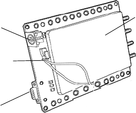
IM5 Reader module
Cable connector
Auxiliary I/O
Connector
RS-232 port
The IM5 Reader Module has holes along the sides that can be
used for mounting. For best results, attach heat sink to case via
the screwholes in the heat sink.
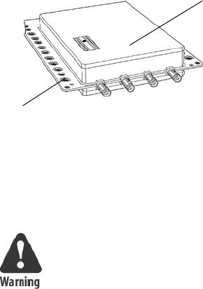
5
IM5 Reader Module Installat ion and Quick Start Guide
Screw holes
IM5 Reader module
Connecting and Getting Started
FCC and Industry Canada regulations limit
exposure to radio frequency (RF) radiation. To
comply with these regulations, operators of this
device must maintain a distance of at least 23 cm.
(9.1 inches) from the cover on the antenna
assembly (The cover on the antenna is the dome
shaped surface). While the device is on, the
operator’s body and parts of the body such as eyes,
hands, or head, must be 23 cm. (9.1 inches) or
farther from the cover of the antenna assembly.
FCC and Industry Canada regulations also require
that the antenna assembly of this device be
installed in accordance with the installation
procedures to allow the operator to comply with
the limit.
Only Intermec antennas and accessories have been
authorized as compliant with FCC and Industry
Canada regulations. Use of antennas and
accessories not authorized:
Smay void the compliance of this product.
Smay result in RF exposures beyond the limits
established for this equipment.
Srequire the user to re-submit their product for
compliance to the FCC and Canadian regulatory
agencies.
6 IM5 Reader Module Installation and Quick Start Guide
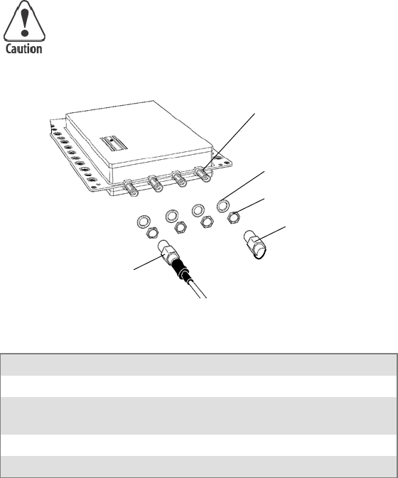
Antenna Installation
1Connect the antenna cable to a port. The four antenna con-
nectors have lock washers and nuts to allow for panel mount-
ing.
2Connect a reverse SMA terminator (Intermec p/n
345-004-001) to any port that does not have an antenna at-
tached.
Each port must have either an antenna or a
terminator connected. Do not apply power to the
Reader unless an antenna cable or terminator is
installed on each antenna port.
Antenna ports (4)
Washers (4)
Nuts (4)
Reverse SMA
terminator
Reverse SMA Antenna cable
Reader LED Explanation
LED Meaning
0Power On
1Reader communicating with host, LED flashes as data transfer
occurs.
2Reader searching for tags
3Reader communicating with a tag, LED flashes as transfer occurs.

7
IM5 Reader Module Installat ion and Quick Start Guide
Troubleshooting
Troubleshooting
Doesn’t Recognize Tag
1. Ensure antenna is properly connected.
2. Ensure reader is connected to your computer.
3. Ensure computer is plugged into AC outlet and computer is On.
4. Ensure tag is within range of antenna.
5. Call Intermec Technical Support 1-800-755-5505 (option 2).
Product Specifications
Dependent upon operating conditions and demands expected. If
used in a normal office environment with good read conditions,
you could expect to read up to 60 tags per second. Tags located
too far away or in poor locations, with respect to interfering
objects, provides poor results.
Firmware Architecture
Firmware Spec Detail
Protocol/Compatibility Communicates in three modes: Ap-
plication Peripheral Interface (API)
and Basic Reader Interface (BRI).
General Specifications
Receiver Spec Detail
Protocol ISO 180006B
Tag data rates 40 kbps
Transmitter Spec Detail
Protocol Intellitag and EPC Gen2
Transmitter type On/Off Keying
Frequency stability <±100 ppm from -25°to +55°C
RF Antenna Connections Spec Detail
Number of antennas up to 4, electronically switched
Antenna port isolation ≥22 dB
Physical Specifications Spec Detail

8 IM5 Reader Module Installation and Quick Start Guide
General Specifications (continued)
Spec DetailPhysical Specifications
Size 8.25 in. x 5.30 in. x 2.9 in.
Weight 38.4 oz. (1.1 kg)
Frequency reference Source Spec Detail
Frequency of operation 902-928 MHz
Usable channels 51
Transmitter Spec Detail
Output power 1.00 Watt maximum
Occupied frequency bandwidth <250 KHz
Environmental Specifications
Temperature Spec Detail
Operating -4°F to +131°F(-20°C to +55°C)
Storage -31°F to +158°F(-35°C to +70°C)
Humidity Spec Detail
Operating 95% Relative
Overall Performance
Dispatch Rates Spec Detail
RFID tag identification rate 60 tags per second
RFID tag data exchange rates Read a tag containing 8 bytes of data
within 12 mS.
Perform a verified write to a tag at an
average rate of 31 mS per byte per
tag.
Write Range Spec Detail
Write range Distances up to 70% of the read dis-
tance under the same conditions.

9
IM5 Reader Module Installat ion and Quick Start Guide
Reliability
Safety and Regulatory Approvals Spec Detail
Reader module UL 60950-1-UL Recognized
Component.
Electromagnetic Compatibility Spec Detail
Reader Module EN55022 (CISPR 22) Class B
digital emissions
EN55024 Immunity
EN61000-3-2, -3 AC Power
Harmonic Emissions and Flicker
Radio Frequency Device Approval Spec Detail
Reader Module FCC Part 15.247
Industry Canada RSS 210
Global Services and Support
Warranty Information
To understand the warranty for your Intermec product, visit the
Intermec web site at http://www.intermec.com and click Service
& Support. The Intermec Global Sales & Service page appears.
From the Service & Support menu, move your pointer over
Support,andthenclickWarranty.
Web Support
Visit the Intermec web site at http://www.intermec.com to
download our current manuals in PDF format. To order printed
versions of the Intermec manuals, contact your local Intermec
representative or distributor.
Visit the Intermec technical knowledge base (Knowledge Cen-
tral) at http://intermec.custhelp.com to review technical infor-
mation or to request technical support for your Intermec prod-
uct.

10 IM5 Reader Module Installation and Quick Start Guide
Telephone Support
These services are available from Intermec Technologies Corpo-
ration.
Service Description
In the U.S.A. and Canada
call 1-800-755-5505 and
choose this option
Order Intermec
products
*Placeanorder.
*Askaboutan
existing order.
1 and then choose 2
Order Intermec
media
Order printer labels
and ribbons
1 and then choose 1
Order spare parts Order spare parts 1 or 2 and then choose 4
Technical Support Talk to technical
support about your
Intermec products.
2 and then choose 2
Service * Get a return
authorization
number for
authorized service
center repair.
*Requestanon-site
repair technician.
2 and then choose 1
Service contracts *Askaboutan
existing contract.
* Renew a contract.
*Inquireabout
repair billing or
other service
invoicing questions.
1 or 2 and then choose 3
Outside the U.S.A. and Canada, contact your local Intermec
representative. To search for your local representative, from the
Intermec web site, click Contact.
11
IM5 Reader Module Installat ion and Quick Start Guide

Corporate Headquarters
6001 36th Avenue West
Everett, Washington 98203
U.S.A.
tel 425.348.2600
fax 425.355.9551
www.intermec.com
IM5 Reader Module Installation and Quick Start Guide
*962-054-121B*
P/N 962-054-121B
e 2004 by Intermec Technologies Corporation. All rights reserved.