Inventek Systems 362 802.11 TYPE WIFI MODULE User Manual Table of Contents
Inventek Systems 802.11 TYPE WIFI MODULE Table of Contents
UserManual.wiki
>
Inventek Systems
>
362 User Manual
User Manual
Navigation menu
Upload a User Manual
Namespaces
Wiki Guide
HTML
PDF
Info
Views
User Manual
Discussion / Help
Navigation
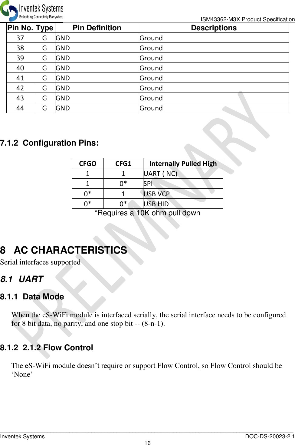
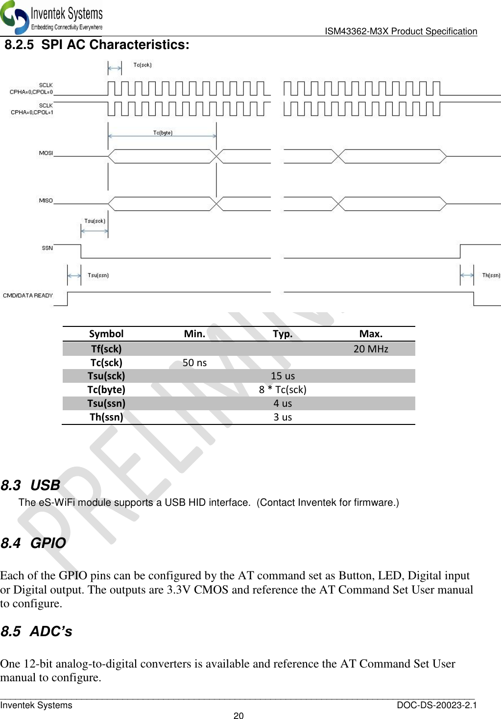
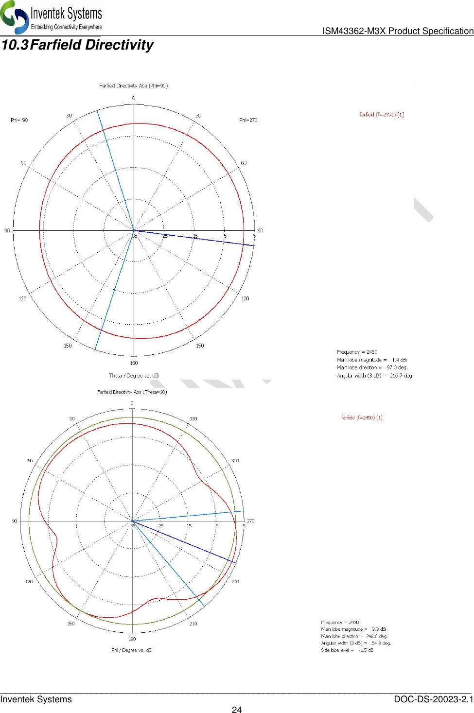
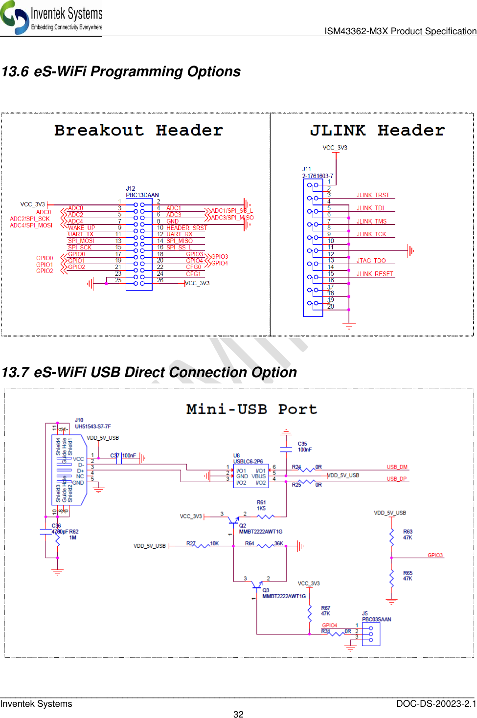
![ISM43362-M3X Product Specification _____________________________________________________________________________________________ Inventek Systems DOC-DS-20023-2.1 18 8.2.1 SPI Communication Overview: With the exception of initial cursor, all communication with the module happens synchronously. In other words, the SPI Master must always poll for every asynchronous event. A typical command flow is provided flow. This is an example using the Direct Connect Soft AP with a TCP communication server. SPI Master SPI Slave Description “\r\n> “ Prompt “AS=0,ABC\r\x15” "\r\n\r\nOK\r\n> " Set Access Point SSID “AD\r\x15” "\r\n\r\nOK\r\n> " Start AP - Direct Mode "P1=0\r\x15" "\r\n\r\nOK\r\n> " Set TCP Protocol "P4=2000\r" "\r\n\r\nOK\r\n> " Set TCP Port "P5=1\r\x15" "\r\n\r\nOK\r\n> " Start TCP COMM Server "MR\r\x15" "\r\n[SOMA]...[EOMA]\r\nOK\r\n> " Read Messages Note: [SOMA] - Start Of Message Asynchronous, [EOMA] - End Of Message Asynchronous The SPI communication is always 16-bit and can be sustained up to 20MHz. The eS-WiFi module after power up or reset will raise CMD/DATA READY pin to signal that the first Data Phase has started. In this mode, the SPI Host must fetch the cursor. As provided by the example above, this is the only time host needs fetch data from slave without issuing a command. The Host will initiate a SPI cycle (lower SSN) and clock out 0x0A (Line Feed) until the CMD/DATA READY pin lowers signaling the end of the Data Phase. The data received will be 0x0d (CR) 0x0A (LF) 0x3E (>) 0x20 (SP). The next rising edge of the CMD/DATA READY pin signals the Command Phase. 8.2.2 SPI Command Phase: The Command Phase indicates the eS-WiFi module is ready to accept a AT Command. The command must include all delimiters and data for the command. Ex. S3=0010\r0123456789 The command must also be sent as one continuous SPI cycle, that is SSN must stay low for the complete command, delimiters, and data. The Host will initiate a SPI cycle (lower SSN) and clock out the command, delimiters and associated data and raise the NSS signal to indicated that the all data has be sent. As result of the NNS raising the eS-WiFi module will lower the CMD/DATA READY pin to signal the end Command Phase. The data that will be clocked back to the Host will be 0x15 (NAK).](https://usermanual.wiki/Inventek-Systems/362/User-Guide-2033722-Page-18.png)
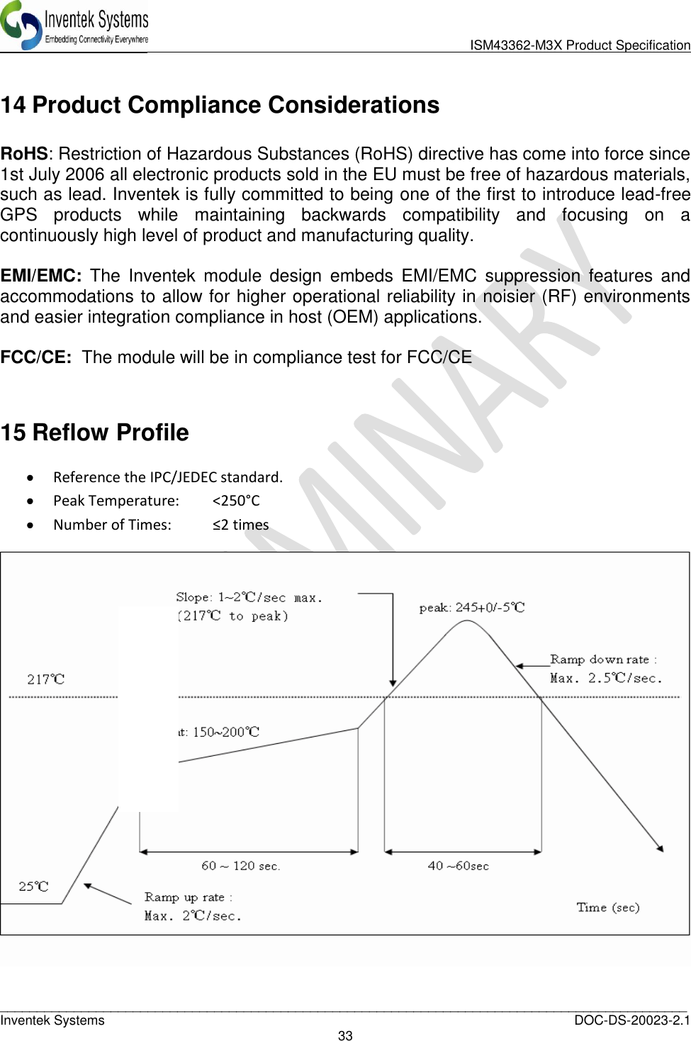
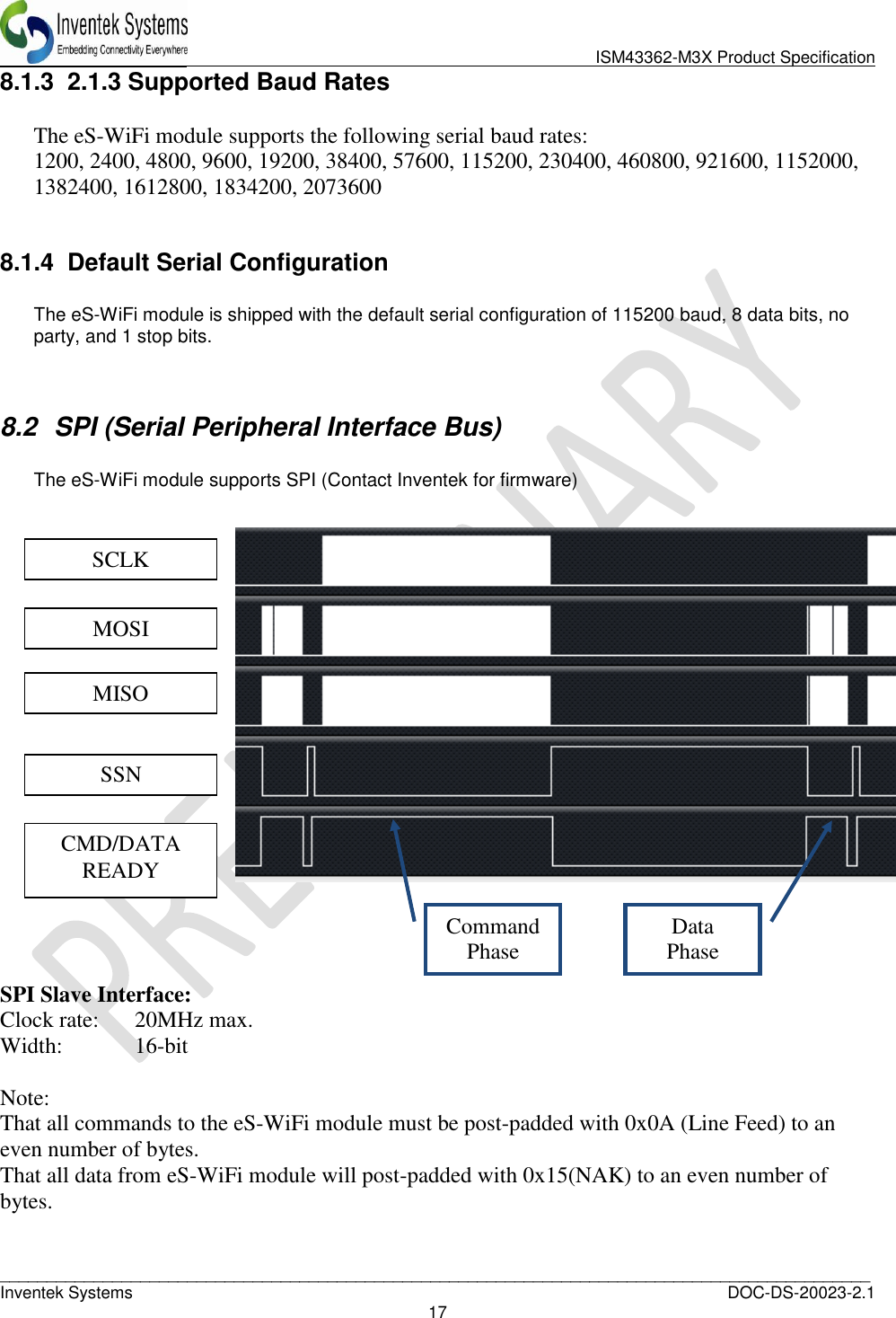
![ISM43362-M3X Product Specification _____________________________________________________________________________________________ Inventek Systems DOC-DS-20023-2.1 19 8.2.3 SPI Data Phase: The Data Phase indicates the eS-WiFi module has data ready for the Host to read. The eS-WiFi module will raise CMD/DATA READY and the Host will initiate a SPI cycle (lower SSN) and clock out 0x0A (Line Feed) until the CMD/DATA READY pin lowers signaling the end of the Data Phase. 8.2.4 SPI Asynchronous Messages: There are certain situations in which the eS-WiFi will issue asynchronous messages: Soft AP (AO/AD Commands), when a device connects to the Soft AP a DHCP assigned message will issued. Ex. [DHCP ] Assigned 00:00:00:00:00:00 has 192.168.10.100 TCP/UDP Communication Servers (P5=1), when a client connects to the server a connected message will be issued. Ex. [TCP SVR] Waiting on connection... [TCP SVR] Accepted 192.168.10.100:2000 [UDP SVR] Accepted 192.168.10.100:2000 With the SPI host interface being synchronous the Host must poll for these messages. This can be done by using the MR (Message Read) command or when a Communication connection the issuing of a R0 command will read all asynchronous message and the result of the R0 command. The asynchronous messages are delineated by the Start Of Message Asynchronous ([SOMA]) and End Of Message Asynchronous ([EOMA]) markers.](https://usermanual.wiki/Inventek-Systems/362/User-Guide-2033722-Page-19.png)