Inventek Systems 362 802.11 TYPE WIFI MODULE User Manual Table of Contents
Inventek Systems 802.11 TYPE WIFI MODULE Table of Contents
User Manual
_____________________________________________________________________________________________
Inventek Systems - www.Inventeksys.com
2 Republic Road • Billerica, MA 01862 • Phone 978-667-1962 Product Specification
1
Inventek
Systems
ISM43362-M3x-L44
Embedded Serial-to-Wi-Fi Module
eS-WiFiTM
802.11 b/g/n
Preliminary Data Sheet

ISM43362-M3X Product Specification
_____________________________________________________________________________________________
Inventek Systems DOC-DS-20023-2.1
2
Table of Contents
1 GENERAL DESCRIPTION ................................................................................................... 4
2 PART NUMBER DETAIL DESCRIPTION .......................................................................... 5
2.1 Ordering Information ...................................................................................................... 5
3 GENERAL FEATURES ......................................................................................................... 5
3.1 Limitations ...................................................................................................................... 6
3.2 Regulatory Compliance .................................................................................................. 6
3.3 FCC User’s Manual Statements ( In Process ): .............................................................. 7
3.4 Industry Canada User’s Manual Statements: .................................................................. 9
4 COMPLEMENTARY DOCUMENTATION ...................................................................... 10
4.1 Inventek Systems .......................................................................................................... 10
5 SPECIFICATIONS ............................................................................................................... 10
5.1 Module Architecture ..................................................................................................... 10
5.2 External Antenna Connections ..................................................................................... 11
5.3 Mechanical Specifications ............................................................................................ 11
5.4 Environmental Specifications ....................................................................................... 12
6 HARDWARE ELECTRICAL SPECIFICATIONS ............................................................. 12
6.1.1 Absolute Maximum Ratings ..................................................................................... 12
6.1.2 Recommended Operating Ratings ............................................................................ 12
6.2 Power Consumption ...................................................................................................... 13
6.2.1 Estimated Power Consumption ................................................................................. 13
6.2.2 Stop Mode ................................................................................................................. 13
7 Pin out ................................................................................................................................... 14
7.1.1 Detailed Pin Description ........................................................................................... 15
7.1.2 Configuration Pins: ................................................................................................... 16
*Requires a 10K ohm pull down .............................................................................................. 16
8 AC CHARACTERISTICS ................................................................................................... 16
8.1 UART ............................................................................................................................ 16
8.1.1 Data Mode ................................................................................................................. 16
8.1.2 2.1.2 Flow Control .................................................................................................... 16
8.1.3 2.1.3 Supported Baud Rates ...................................................................................... 17
8.1.4 Default Serial Configuration ..................................................................................... 17
8.2 SPI (Serial Peripheral Interface Bus) ............................................................................ 17
8.2.1 SPI Communication Overview: ................................................................................ 18
8.2.2 SPI Command Phase: ................................................................................................ 18
8.2.3 SPI Data Phase: ......................................................................................................... 19
8.2.4 SPI Asynchronous Messages: ................................................................................... 19
8.2.5 SPI AC Characteristics: ............................................................................................ 20
8.3 USB ............................................................................................................................... 20
8.4 GPIO ............................................................................................................................. 20
8.5 ADC’s ........................................................................................................................... 20
9 Wi-Fi RF Specification ......................................................................................................... 21
9.1.1 RF Specification........................................................................................................ 21

ISM43362-M3X Product Specification
_____________________________________________________________________________________________
Inventek Systems DOC-DS-20023-2.1
3
10 Antenna Patterns ................................................................................................................... 22
10.1 External Antenna .......................................................................................................... 22
10.2 PCB Etch antenna gain on the evaluation board ........................................................... 23
10.3 Farfield Directivity........................................................................................................ 24
11 On Board Processor .............................................................................................................. 25
12 ISM43362-M3x-L44 FOOTPRINT ...................................................................................... 26
12.1 Module’s package dimensions (mm) ............................................................................ 26
13 Typical Application Circuit .................................................................................................. 27
13.1 Reference Schematic (EVB) ......................................................................................... 28
13.2 USB to UART ............................................................................................................... 29
13.3 Connecting Microcontroller to eS-WiFi UART ........................................................... 30
13.4 EXTERNAL FLASH FOR OVER THE AIR UPGRADE........................................... 31
13.5 JTAG and Reset Connections ....................................................................................... 31
13.6 eS-WiFi Programming Options .................................................................................... 32
13.7 eS-WiFi USB Direct Connection Option ...................................................................... 32
14 Product Compliance Considerations ..................................................................................... 33
15 Reflow Profile ....................................................................................................................... 33
16 Packaging Information .......................................................................................................... 34
16.1 MSL Level / Storage Condition .................................................................................... 34
16.2 Device baking requirements prior to assembly ............................................................. 35
Module’s Assembly Instructions .............................................................................................. 35
17 REVISION CONTROL ........................................................................................................ 36
18 CONTACT INFORMATION ............................................................................................... 36

ISM43362-M3X Product Specification
_____________________________________________________________________________________________
Inventek Systems DOC-DS-20023-2.1
4
1 GENERAL DESCRIPTION
The Inventek ISM43362-M3X-L44 is an embedded (eS-WiFiTM) wireless Internet
Connectivity device. The Wi-Fi module hardware consists of an STM M3 Cortex host
processor, integrated antenna (or optional ext. antenna) and Broadcom Wi-Fi device all
interconnected. The module provides UART, USB and SPI interfaces enabling
connection to an embedded design. The Wi-Fi module requires no operating system
and has a completely integrated TCP/IP Stack that only requires AT commands to
establish connectivity for your wireless product, minimizing development time, testing
routines and certification. The low cost, small foot print (14.5 mm x 30 mm) and ease of
design-in make it ideal for a range of embedded applications. The module hardware can
be used with Inventek’s AT Command set or the Broadcom’s WICEDTM SDK.
Summary of Key Features:
802.11 b/g/ n compliant based on Broadcom MAC/Baseband/Radio device.
Fully contained TCP/IP stack minimizing host CPU requirements.
Configurable using AT commands.
Host interface: UART, SPI, or USB.
Network features ICMP (Ping), ARP, DHCP,TCP, UDP.
Low power operation (3.3V supply) with built-in low power modes.
Secure Wi-Fi authentication WEP-128, WPA-PSK (TKIP), WPA2-PSK.
Proven Interoperability … Connects with other vendor’s b/g/n Access Points in the
Wireless LAN.
Supported by Broadcom WICEDTM SDK
Typical Applications:
PDA, Pocket PC, computing devices.
Building automation and smart energy control.
Industrial sensing and remote equipment monitoring.
Warehousing, logistics and freight management.
PC and gaming peripherals.
Printers, scanners, alarm and video systems.
Medical applications including patient monitoring and remote diagnostics.

ISM43362-M3X Product Specification
_____________________________________________________________________________________________
Inventek Systems DOC-DS-20023-2.1
5
2 PART NUMBER DETAIL DESCRIPTION
2.1 Ordering Information
Device
Description
Ordering Number
ISM43362-M3G-L44
802.11 Module, STM32F205 (1 Meg),
Commercial Temp (UART,SPI, Internal
Etched Antenna)
ISM43362-M3G-L44-E
ISM43362-M3G-L44
802.11 Module, STM32F205 (1 Meg),
Commercial Temp (UART,SPI, External
U.FL Connector))
ISM43362-M3G-L44-U
ISM43362-M3G-EVB-E
Evaluation Board, USB cable, with
ISM43362-M3G-L44-E, Quick Start Guide
ISM43362-M3G-EVB-E
3 GENERAL FEATURES
Based on the Broadcom BCM43362 MAC/Baseband/Radio device.
Supports Broadcom WICED SDK
CPU ARM Cortex™-M3 32-bit RISC core from ST Microelectronics.
Host UART, SPI, or USB HID interface.
IEEE 802.11n D7.0 -OFDM-72.2 Mbps -single stream w/20 Mhz, Short GI
IEEE 802.11g (OFDM 54 Mbps)
IEEE 802.11b (DSSS 11Mbps)
IEEE 802.11i (Security)
o WPA (Wi-Fi Protected Access) –PSK/TKIP
o WPA2 (Wi-Fi Protected Access 2)- AES/CCMP/802.1x Authentication
Inputs +3.3 V tolerant
5 GPIO, 5 ADC (Note: SPI interface utilizes ADC pins.)
The devices operate from a 3.0 to 3.6 V power supply.
-40 to +85 °C temperature range
Power-saving mode allows the design of low-power applications.
Lead Free Design which is compliant with ROHS requirements.
EMI/EMC Metal Shield for best RF performance in noisy environments and to
accommodate for lower RF emissions/signature for easier FCC compliance.
FCC/CE Compliance Certification (In process).
ISM43362-M3X Product Specification
_____________________________________________________________________________________________
Inventek Systems DOC-DS-20023-2.1
6
3.1 Limitations
Inventek Systems products are not authorized for use in safety-critical applications
(such as life support) where a failure of the Inventek Systems product would
reasonably be expected to cause severe personal injury or death.
3.2 Regulatory Compliance
CE
Regulator
Status
FCC
07P-362
CE
10147A-362
RoHS
Compliant

ISM43362-M3X Product Specification
_____________________________________________________________________________________________
Inventek Systems DOC-DS-20023-2.1
7
3.3 FCC and IC User’s Manual Statements ( Pending ):
OEM INSTRUCTIONS:
This module is limited to OEM installation only.
OEM integrators must ensure that the end-user has no manual instructions to remove or
install the module.. OEM’s must comply with FCC marking regulation part 15 declaration
of conformity (Section 2.925(e)).
This module is to be installed only in mobile or fixed applications (Please refer to FCC
CFR 47 Part 2.1091(b) for a definition of mobile and fixed devices).
Separate approval is required for all other operating configurations, including portable
configurations with respect to FCC CFR 47 Part 2.1093, and different antenna
configurations.
The antennas used with this module must be installed to provide a separation distance
of at least 20cm from all persons, and must not be co-located or transmit simultaneously
with any other antenna or transmitter, except in accordance with FCC multi transmitter
product procedures.
The ISM43362 Module has been designed to operate with the following antennas and
gains. Use with other antenna types or with these antenna types at higher gains is
strictly prohibited.
Manufacturer
Type of
Antenna
Model
Gain dB
Type of
Connector
Inventek
U.Fl port
Antenna
W24P-U
2.15
Unique
Connector
Inventek
Trace Antenna
NA
0
Permanent
integral
ISM43362-M3X Product Specification
_____________________________________________________________________________________________
Inventek Systems DOC-DS-20023-2.1
8
Warning: changes or modifications not expressly approved by the party responsible for
compliance could void the user’s authority to operate this equipment.
A clearly visible label is required on the outside of the user’s (OEM) enclosure stat the
following text:
Contains FCC ID: O7P-362
Contains IC: 10147A-362
This transmitter module has been certified for FCC Part 15 operation; when installed in
a host device, the host manufacturer is responsible for making sure that the host device
with the transmitter installed continues to be compliant with Part 15B unintentional
radiator requirements

ISM43362-M3X Product Specification
_____________________________________________________________________________________________
Inventek Systems DOC-DS-20023-2.1
9
Industry Canada User’s Manual Statements:
IC RSS-210/RSS-Gen Notices-
Operation is subject to the following two conditions: (1) this device may not cause
interference, and (2) this device must accept any interference, including interference
that may cause undesired operation of this device.
L’opѐration est soumise aux deux conditions suivantes: (1) cet appareil ne peut pas
provoquer d’interfѐrences et (2) cet apparial doit accepter toute interfѐrence, y compris
les interfѐrences qui peuvent causer un mauvis fonctionment de l’appareil.
Under Industry Canada regulations, this radio transmitter may only operate using an
antenna of a type and maximum (or lesser) gain approved for the transmitter by Industry
Canada. To reduce potential radio interference to other users, the antenna type and its
gain should be so chosen that the equivalent isotropically radiated power (e.i.r.p.) is not
more than that necessary for successful communication.
Sous la rѐglementation d’Industrie Canada, ce transmetteur radio ne peut fonctionner
en utilisant une antenne d’un type et un maximum (ou moins) gain approuvѐes pour
l’ѐmetteur par Industrie Canada. Pour rѐduire le risqué d’interference aux autres
utilisateures, le type d’antenne et son gain doivent être choisis de maniѐre que la
puissance isotrpe rayonnѐe ѐquivalente (PIRE) ne dѐpasse pas ce qui est nѐcessaire
pour une communication rѐussie.
The radio transmitter has been approved by Industry Canada to operate with the
antenna types listed above with the maximum permissible gain and required antenna
impedance for each antenna type indicated. Antenna types not included in this list
having a gain greater than the maximum gain indicated for that type, are strictly
prohibited for use with this device.
Cet ѐmetteur de radio a ѐtѐ approuvѐ par Industrie Canada pour fonctionner avec les
types d’antennes ѐnumѐrѐes ci-dessus avec le gain maximal admissible et impѐdance
d’antenna requise pour chaque type d’antenne indiquѐ. Types d’antennes ne figurant
pas dans cette liste, ayant un gain supѐrieur au gain maximum indiquѐ pour ce type,
sont strictement interdites pour l’utilisation avec cet appareil.
ISM43362-M3X Product Specification
_____________________________________________________________________________________________
Inventek Systems DOC-DS-20023-2.1
10
4 COMPLEMENTARY DOCUMENTATION
4.1 Inventek Systems
Evaluation Board
o ISM43362-M3G-EVB Evaluation Board Specification
o EVB Users Guide
o Quick Start Guide
o eS-WiFi Demo software (includes EVB Drivers and Firmware)
AT Command Set
o AT Command Set User’s Manual
o AT Command Set Quick Reference Guide
Firmware
OrCAD Schematic Symbol
PADS Land Pattern
FCC Test Report ( In Process)
5 SPECIFICATIONS
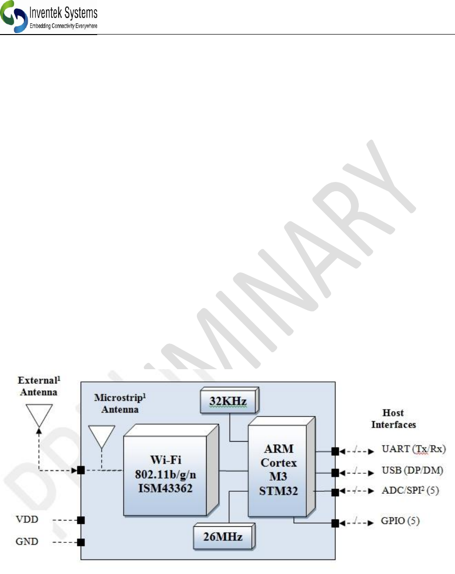
5.1 Module Architecture
Figure 1 Inventek’s ISM43362-M3 General Block Diagram
Note: 1. ADC1-ADC4 can also be used as SPI port
2. Antenna Options: Integrated microstrip antenna or U.fl connector for an external antenna.
ISM43362-M3X Product Specification
_____________________________________________________________________________________________
Inventek Systems DOC-DS-20023-2.1
11
5.2 External Antenna Connections
ISM43362-M3X-L44-U module is designed for use with an external antenna via a
connection using the U.FL connector.
Item
Description
Connector
U.FL series
Manufacturer
I-PEX Co., Ltd.
Part No.
20279-001E-01
Height
1.25 mm
Width
2 mm
DC
3.0 – 5.0 V
Table 1 On-Board Antenna Connector
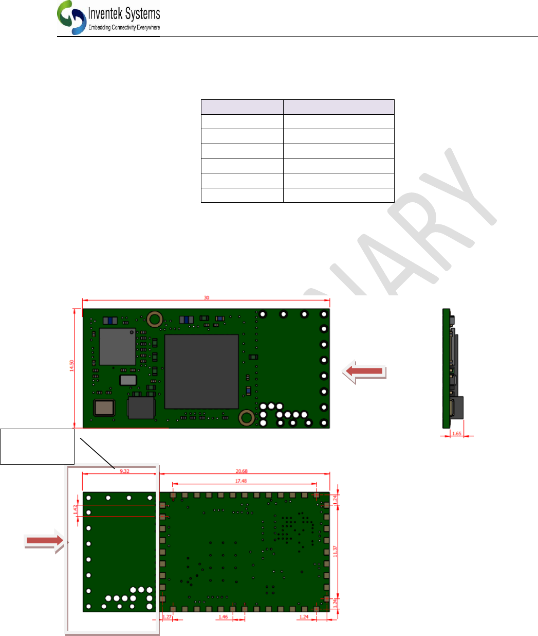
5.3 Mechanical Specifications
The Physical dimensions of this eS-WiFi Module are as follow:
Figure 2: ANTENNA IS IN ETCH
* External Antenna does not require keep out area
*Keep out area should ideally have the antenna handing off the side of the PCB for best
performance.
*The ISM43362-M3X-L44 U and E have the same footprint.
* Keep out
Area
ISM43362-M3X Product Specification
_____________________________________________________________________________________________
Inventek Systems DOC-DS-20023-2.1
12
Items
Description
ISM43362-M3X-L44-E /U
Length
30 mm (-/+0.5 mm)
Width
14.5 mm (-/+0.5 mm)
Height
2.5 ± 0.2 mm
Package
44 pin LGA
5.4 Environmental Specifications
Item
Description
Operating temperature range
-40 deg. C to +85 deg. C
Storage temperature range
-40 deg. C to +85 deg. C
Humidity
95% max non-condensing
Note 1: The ISM43362-M3X supports a functional operating range of -40°C to +85°C.
However the optimal RF performance specified in this data sheet is only guaranteed for
temperatures from -10°C to +65°C
6 HARDWARE ELECTRICAL SPECIFICATIONS
6.1.1 Absolute Maximum Ratings
6.1.2 Recommended Operating Ratings
Symbol
Min.
Typ.
Max.
Unit.
VDD
3.0
3.3
3.6
V
VBAT
3.0
3.3
3.6
V
Symbol
Description
Min
Max
Unit
VDD
Input supply Voltage
-0.4
3.7
V
VBAT
Battery Backup
-0.4
3.6
V
ISM43362-M3X Product Specification
_____________________________________________________________________________________________
Inventek Systems DOC-DS-20023-2.1
13
6.2 Power Consumption
6.2.1 Estimated Power Consumption
Mode/Description
802.x
Voltage
Typ.
(RMS)
Max.
Unit
Running Full Power(1)
/n
3.3V
110
mA
Running in Power Save Mode
/n
3.3V
55
110(1)
mA
Wi-Fi Radio Off
b/g/n
30
mA
Stop Mode(2)
10
mA
Note:
(1)During transmit the max can reach 340 mA burst of not more than 5ms.
(2)Available in Firmware release1.3 or later only.
The eS-WiFi modules support multiple power saving modes. Please see the power savings
application note for more detailed information
6.2.2 Stop Mode
Stop Mode is initiated by software and exited by the Wakeup pin. (Wakeup pin is 3.3 volt
tolerant). The wakeup pin is an external interrupt pin that on the rising edge will cause the
module to exit stop mode. It is an edge trigged input. It is critical to have no glitch on this line.
ISM43362-M3X Product Specification
_____________________________________________________________________________________________
Inventek Systems DOC-DS-20023-2.1
14
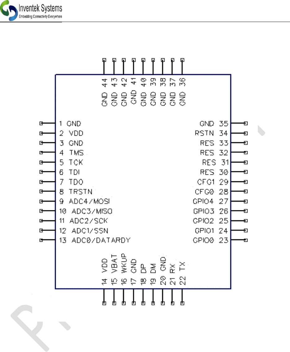
7 Pin out
ISM43362-M3X Product Specification
_____________________________________________________________________________________________
Inventek Systems DOC-DS-20023-2.1
15
7.1.1 Detailed Pin Description
Pin No.
Type
Pin Definition
Descriptions
1
G
GND
Ground
2
I
VDD
3.3V
3
G
GND
Ground
4
I/O
RES
Reserved
5
I/O
RES
Reserved
6
I/O
RES
Reserved
7
I/O
RES
Reserved
8
I/O
RES
Reserved
9
I
ADC 4 / SPI_MOSI
ADC Input Pins or SPI
(Refer to SPI Section 8.2)
10
I
ADC 3 / SPI_MISO
11
I
ADC 2 / SPI_SCK
12
I
ADC 1 / SPI_SSN
13
I
ADC 0/ DATARDY
14
I
VDD
3.3V
15
I
VBAT
3.3V
16
I
Wakeup
(Refer to Section 6.2.2)
17
G
GND
Ground
18
I
DP
USB Data Plus (Refer to Table 7.1.2)
19
I/O
DM
USB Data Minus (Refer to Table 7.1.2 )
20
G
GND
Ground
21
I/O
RX
UART Receive (Refer to section 8.1 )
22
I/O
TX
UART Transmit (Refer to section 8.1 )
23
I/O
GPIO 0
General Purpose Interface Pins
24
I/O
GPIO 1
25
I/O
GPIO 2
26
I/O
GPIO 3
27
I/O
GPIO 4
28
I
CFGO
Configuration Pin 0 (Refer to Table 7.1.2 )
29
I
CFG1
Configuration Pin 1 (Refer to Table 7.1.2 )
30
O
RES
Reserved
31
I
RES
Reserved
32
I
RES
Reserved
33
I
BOOT 0
Reserved
34
I
RSTN
Reset (See STM32F205 NRST specification )
35
G
GND
Ground
36
G
GND
Ground
ISM43362-M3X Product Specification
_____________________________________________________________________________________________
Inventek Systems DOC-DS-20023-2.1
16
Pin No.
Type
Pin Definition
Descriptions
37
G
GND
Ground
38
G
GND
Ground
39
G
GND
Ground
40
G
GND
Ground
41
G
GND
Ground
42
G
GND
Ground
43
G
GND
Ground
44
G
GND
Ground
7.1.2 Configuration Pins:
CFGO
CFG1
Internally Pulled High
1
1
UART ( NC)
1
0*
SPI
0*
1
USB VCP
0*
0*
USB HID
*Requires a 10K ohm pull down
8 AC CHARACTERISTICS
Serial interfaces supported
8.1 UART
8.1.1 Data Mode
When the eS-WiFi module is interfaced serially, the serial interface needs to be configured
for 8 bit data, no parity, and one stop bit -- (8-n-1).
8.1.2 2.1.2 Flow Control
The eS-WiFi module doesn’t require or support Flow Control, so Flow Control should be
‘None’
ISM43362-M3X Product Specification
_____________________________________________________________________________________________
Inventek Systems DOC-DS-20023-2.1
17
8.1.3 2.1.3 Supported Baud Rates
The eS-WiFi module supports the following serial baud rates:
1200, 2400, 4800, 9600, 19200, 38400, 57600, 115200, 230400, 460800, 921600, 1152000,
1382400, 1612800, 1834200, 2073600
8.1.4 Default Serial Configuration
The eS-WiFi module is shipped with the default serial configuration of 115200 baud, 8 data bits, no
party, and 1 stop bits.
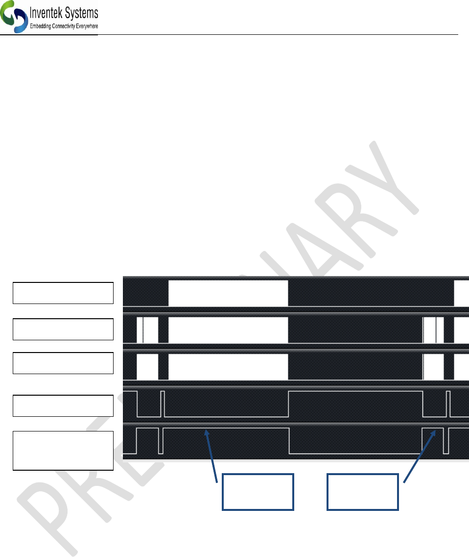
8.2 SPI (Serial Peripheral Interface Bus)
The eS-WiFi module supports SPI (Contact Inventek for firmware)
SPI Slave Interface:
Clock rate: 20MHz max.
Width: 16-bit
Note:
That all commands to the eS-WiFi module must be post-padded with 0x0A (Line Feed) to an
even number of bytes.
That all data from eS-WiFi module will post-padded with 0x15(NAK) to an even number of
bytes.
Command
Phase
Data
Phase
SCLK
MOSI
MISO
SSN
CMD/DATA
READY

ISM43362-M3X Product Specification
_____________________________________________________________________________________________
Inventek Systems DOC-DS-20023-2.1
18
8.2.1 SPI Communication Overview:
With the exception of initial cursor, all communication with the module happens synchronously.
In other words, the SPI Master must always poll for every asynchronous event.
A typical command flow is provided flow. This is an example using the Direct Connect Soft AP
with a TCP communication server.
SPI Master
SPI Slave
Description
“\r\n> “
Prompt
“AS=0,ABC\r\x15”
"\r\n\r\nOK\r\n> "
Set Access Point SSID
“AD\r\x15”
"\r\n\r\nOK\r\n> "
Start AP - Direct Mode
"P1=0\r\x15"
"\r\n\r\nOK\r\n> "
Set TCP Protocol
"P4=2000\r"
"\r\n\r\nOK\r\n> "
Set TCP Port
"P5=1\r\x15"
"\r\n\r\nOK\r\n> "
Start TCP COMM Server
"MR\r\x15"
"\r\n[SOMA]...[EOMA]\r\nOK\r\n>
"
Read Messages
Note: [SOMA] - Start Of Message Asynchronous, [EOMA] - End Of Message Asynchronous
The SPI communication is always 16-bit and can be sustained up to 20MHz. The eS-WiFi
module after power up or reset will raise CMD/DATA READY pin to signal that the first Data
Phase has started. In this mode, the SPI Host must fetch the cursor. As provided by the example
above, this is the only time host needs fetch data from slave without issuing a command.
The Host will initiate a SPI cycle (lower SSN) and clock out 0x0A (Line Feed) until the
CMD/DATA READY pin lowers signaling the end of the Data Phase. The data received will be
0x0d (CR) 0x0A (LF) 0x3E (>) 0x20 (SP).
The next rising edge of the CMD/DATA READY pin signals the Command Phase.
8.2.2 SPI Command Phase:
The Command Phase indicates the eS-WiFi module is ready to accept a AT Command. The
command must include all delimiters and data for the command.
Ex. S3=0010\r0123456789
The command must also be sent as one continuous SPI cycle, that is SSN must stay low for the
complete command, delimiters, and data.
The Host will initiate a SPI cycle (lower SSN) and clock out the command, delimiters and
associated data and raise the NSS signal to indicated that the all data has be sent. As result of the
NNS raising the eS-WiFi module will lower the CMD/DATA READY pin to signal the end
Command Phase.
The data that will be clocked back to the Host will be 0x15 (NAK).

ISM43362-M3X Product Specification
_____________________________________________________________________________________________
Inventek Systems DOC-DS-20023-2.1
19
8.2.3 SPI Data Phase:
The Data Phase indicates the eS-WiFi module has data ready for the Host to read. The eS-WiFi
module will raise CMD/DATA READY and the Host will initiate a SPI cycle (lower SSN) and
clock out 0x0A (Line Feed) until the CMD/DATA READY pin lowers signaling the end of the
Data Phase.
8.2.4 SPI Asynchronous Messages:
There are certain situations in which the eS-WiFi will issue asynchronous messages:
Soft AP (AO/AD Commands), when a device connects to the Soft AP a DHCP assigned
message will issued.
Ex. [DHCP ] Assigned 00:00:00:00:00:00 has 192.168.10.100
TCP/UDP Communication Servers (P5=1), when a client connects to the server a
connected message will be issued.
Ex. [TCP SVR] Waiting on connection...
[TCP SVR] Accepted 192.168.10.100:2000
[UDP SVR] Accepted 192.168.10.100:2000
With the SPI host interface being synchronous the Host must poll for these messages. This can
be done by using the MR (Message Read) command or when a Communication connection the
issuing of a R0 command will read all asynchronous message and the result of the R0 command.
The asynchronous messages are delineated by the Start Of Message Asynchronous ([SOMA])
and End Of Message Asynchronous ([EOMA]) markers.
ISM43362-M3X Product Specification
_____________________________________________________________________________________________
Inventek Systems DOC-DS-20023-2.1
20
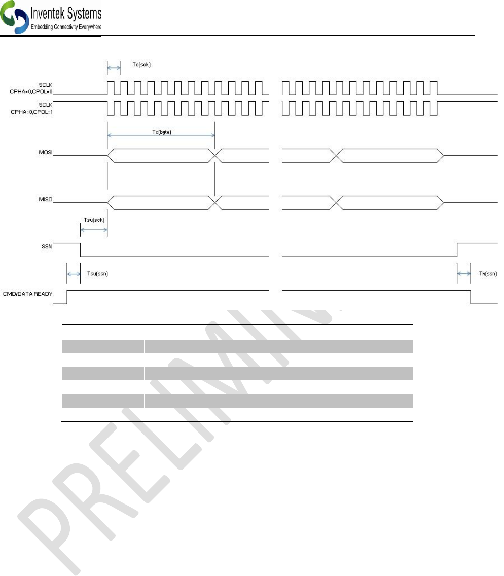
8.2.5 SPI AC Characteristics:
Symbol
Min.
Typ.
Max.
Tf(sck)
20 MHz
Tc(sck)
50 ns
Tsu(sck)
15 us
Tc(byte)
8 * Tc(sck)
Tsu(ssn)
4 us
Th(ssn)
3 us
8.3 USB
The eS-WiFi module supports a USB HID interface. (Contact Inventek for firmware.)
8.4 GPIO
Each of the GPIO pins can be configured by the AT command set as Button, LED, Digital input
or Digital output. The outputs are 3.3V CMOS and reference the AT Command Set User manual
to configure.
8.5 ADC’s
One 12-bit analog-to-digital converters is available and reference the AT Command Set User
manual to configure.
ISM43362-M3X Product Specification
_____________________________________________________________________________________________
Inventek Systems DOC-DS-20023-2.1
21
9 Wi-Fi RF Specification
9.1.1 RF Specification
Conditions: VDD=3.3V; VDDIO=3.3V; TEMP: 25°C
Feature
Description
WLAN Standard
IEEE 802.11b/g/n, Wi-Fi compliant
Frequency Range
2.400 GHz ~ 2.497 GHz (2.4 GHz ISM Band)
Number of Channels
Ch1 ~ Ch14
Modulation
802.11 g/n : OFDM /64-QAM,16-QAM, QPSK, BPSK
802.11b : CCK, DQPSK, DBPSK
Output Power
802.11b /11Mbps : 20 dBm ± 1.5 dB
802.11g /54Mbps: 20 dBm ± 1.5 dB
802.11n /72Mbps: 20 dBm ± 1.5 dB
Receive Sensitivity
(11n,20MHz)
@10% PER
- MCS=0 PER @ -86 dBm, typical
- MCS=1 PER @ -85 dBm, typical
- MCS=2 PER @ -85 dBm, typical
- MCS=3 PER @ -84 dBm, typical
- MCS=4 PER @ -80 dBm, typical
- MCS=5 PER @ -78 dBm, typical
- MCS=6 PER @ -72 dBm, typical
- MCS=7 PER @ -69 dBm, typical
Receive Sensitivity
(11g) @10% PER
- 6Mbps PER @ -89 dBm, typical
- 9Mbps PER @ -88 dBm, typical
- 12Mbps PER @ -88 dBm, typical
- 18Mbps PER @ -87 dBm, typical
- 24Mbps PER @ -83 dBm, typical
- 36Mbps PER @ -80 dBm, typical
- 48Mbps PER @ -75 dBm, typical
- 54Mbps PER @ -72 dBm, typical
Receive Sensitivity
(11b) @10% PER
- 1Mbps PER @ -93 dBm, typical
- 2Mbps PER @ -91 dBm, typical
- 5.5Mbps PER @ -89 dBm, typical
- 11Mbps PER @ -87 dBm, typical
Data Rates
802.11b : 1, 2, 5.5, 11Mbps
802.11g : 6, 9, 12, 18, 24, 36, 48, 54Mbps
Data Rate
(20MHz ,Long GI,800ns)
802.11n: 6.5, 13, 19.5, 26, 39, 52, 58.5, 65Mbps
ISM43362-M3X Product Specification
_____________________________________________________________________________________________
Inventek Systems DOC-DS-20023-2.1
22
Data Rate
(20MHz ,short GI,400ns)
802.11n : 7.2, 14.4, 21.7, 28.9, 43.3, 57.8, 65,72.2Mbps
Maximum Input Level
802.11b : -10 dBm
802.11g : -10 dBm
10 Antenna Patterns
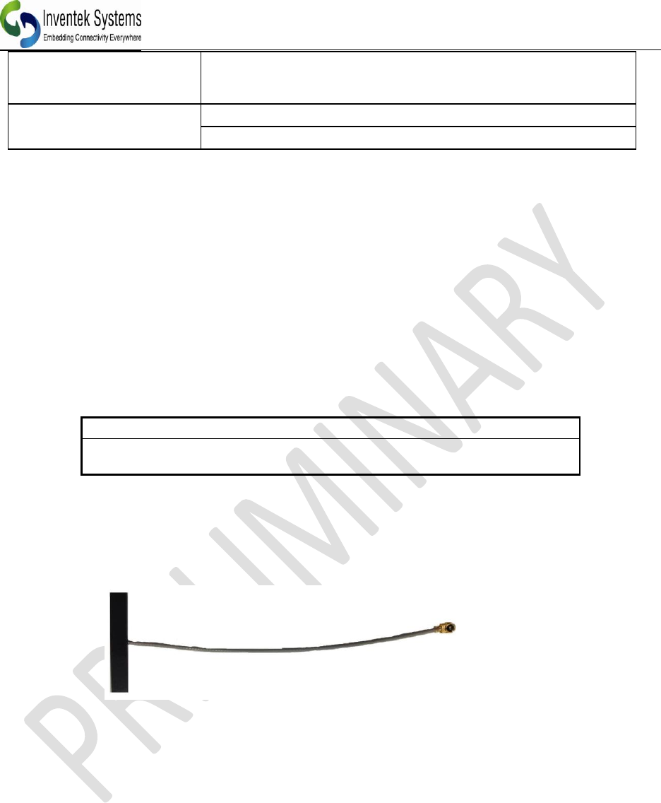
10.1 External Antenna
The U.FLPCB antenna has passed FCC and CE. The part number is W24P-U. It is a 2.4 GHz
PCB antenna with an u.FL connector.
The es-Wifi family of Wi-Fi products comes with two different antenna offerings:
ISM43362-M3G-L44-E
PCB Etch Antenna
ISM43362-M3G-L44-U
U.FL connector for external antenna
The PCB U.FL antenna that will be used for FCC and CE certified can be found on the Inventek
Website.
ISM43362-M3X Product Specification
_____________________________________________________________________________________________
Inventek Systems DOC-DS-20023-2.1
23
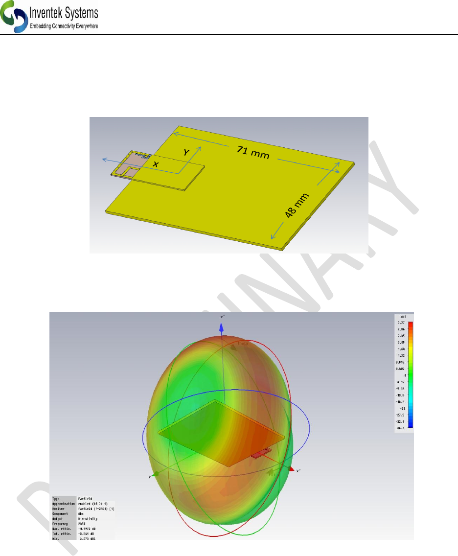
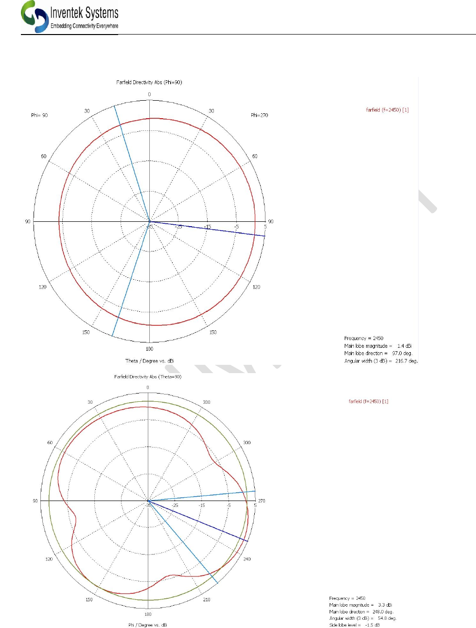
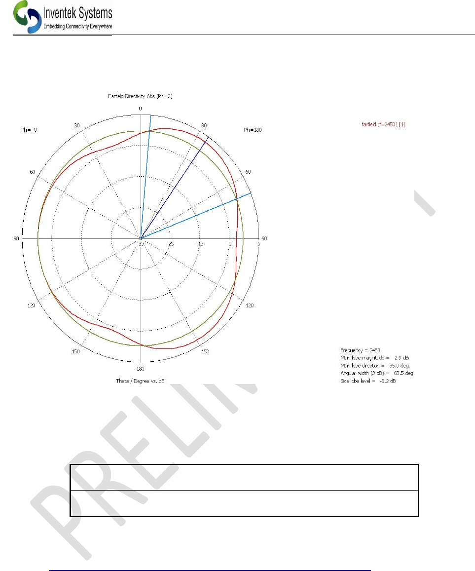
10.2 PCB Etch antenna gain on the evaluation board
The es-WiFi PCB etch antenna performance is shown below. This etch antenna will be FCC and
CE certified and the radiation patterns shown below are based on simulation using our evaluation
boards that has a ground plane 71 x 48mm.
ISM43362-M3X Product Specification
_____________________________________________________________________________________________
Inventek Systems DOC-DS-20023-2.1
24
10.3 Farfield Directivity
ISM43362-M3X Product Specification
_____________________________________________________________________________________________
Inventek Systems DOC-DS-20023-2.1
25
11 On Board Processor
The eS-WiFi module is available with ST Microcontroller, F205 family of processors.
ISM43362-M3G-L44 -E
STM32F205 (1 Meg), Flash
Microcontroller
ISM43362-M3G-L44-U
STM32F103 (1Meg), Flash
Microcontroller)
See theSTM32F205 specification from ST Microelectronics for UART, SPI (Slave Mode) and
USB Device.
http://www.st.com/internet/mcu/product/164485.jsp#DATASHEET
ISM43362-M3X Product Specification
_____________________________________________________________________________________________
Inventek Systems DOC-DS-20023-2.1
26
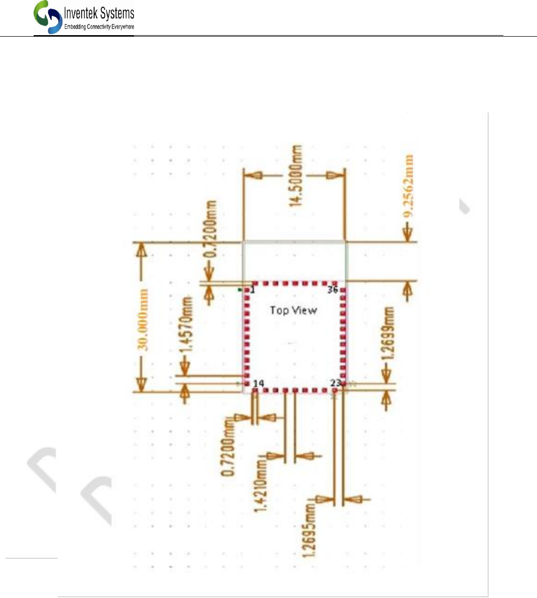
12 ISM43362-M3x-L44 FOOTPRINT
12.1 Module’s package dimensions (mm)
ISM43362-M3X Product Specification
_____________________________________________________________________________________________
Inventek Systems DOC-DS-20023-2.1
27
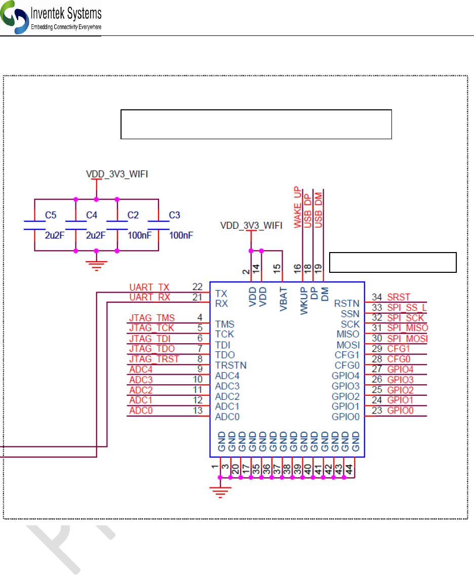
13 Typical Application Circuit
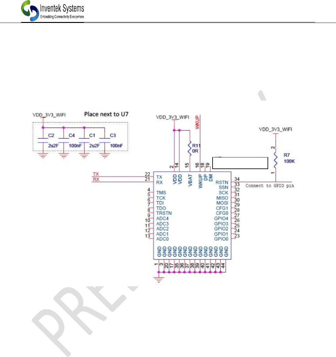
This is the minimum number of wires required to be connected to your microcontroller for
operation in UART mode. You may also want to bring out the JTAG lines for firmware
upgrades.
ISM43362-M3G
ISM43362-M3X Product Specification
_____________________________________________________________________________________________
Inventek Systems DOC-DS-20023-2.1
28
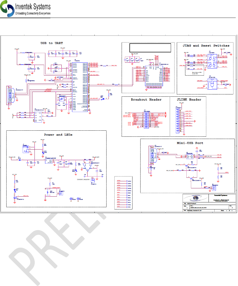
13.1 Reference Schematic (EVB)
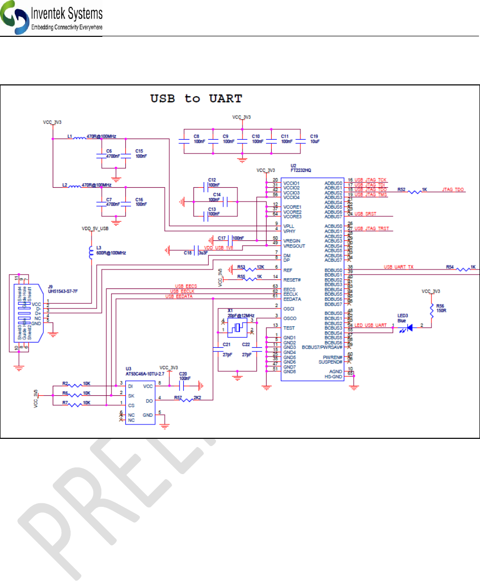
Note: Second USB port J10 is not installed on the evaluation boards. Please contact Inventek
if you want to use USB or SPI mode.
Typical application circuits please refer to schematic below. For a *.pdf version please visit the
Wi-Fi evaluation board website, www.Inventeksys.com.
ISM43362-M3G
ISM43362-M3X Product Specification
_____________________________________________________________________________________________
Inventek Systems DOC-DS-20023-2.1
29
13.2 USB to UART
ISM43362-M3X Product Specification
_____________________________________________________________________________________________
Inventek Systems DOC-DS-20023-2.1
30
13.3 Connecting Microcontroller to eS-WiFi UART
ISM43362-M3G
ISM43362-M3G
ISM43362-M3X Product Specification
_____________________________________________________________________________________________
Inventek Systems DOC-DS-20023-2.1
31
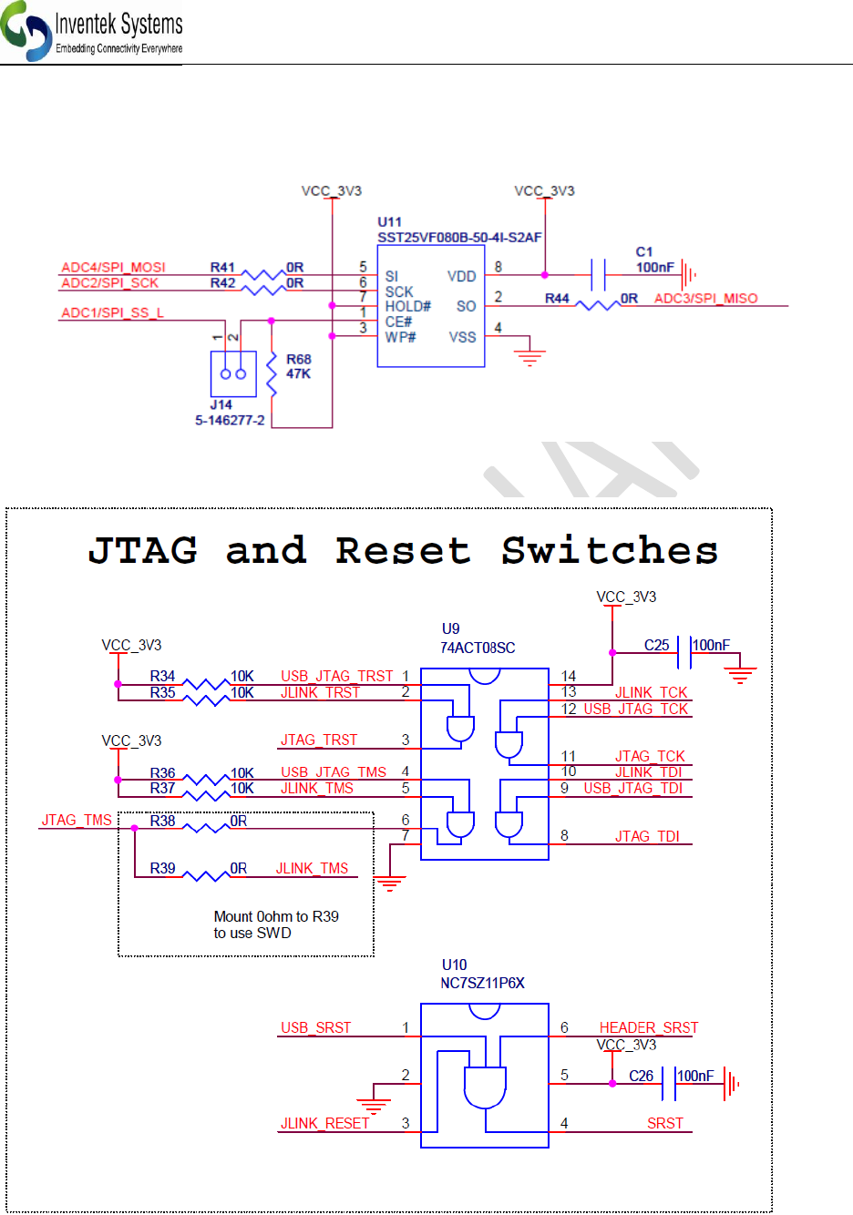
13.4 EXTERNAL FLASH FOR OVER THE AIR UPGRADE
(In development, contact Inventek)
13.5 JTAG and Reset Connections
ISM43362-M3X Product Specification
_____________________________________________________________________________________________
Inventek Systems DOC-DS-20023-2.1
32
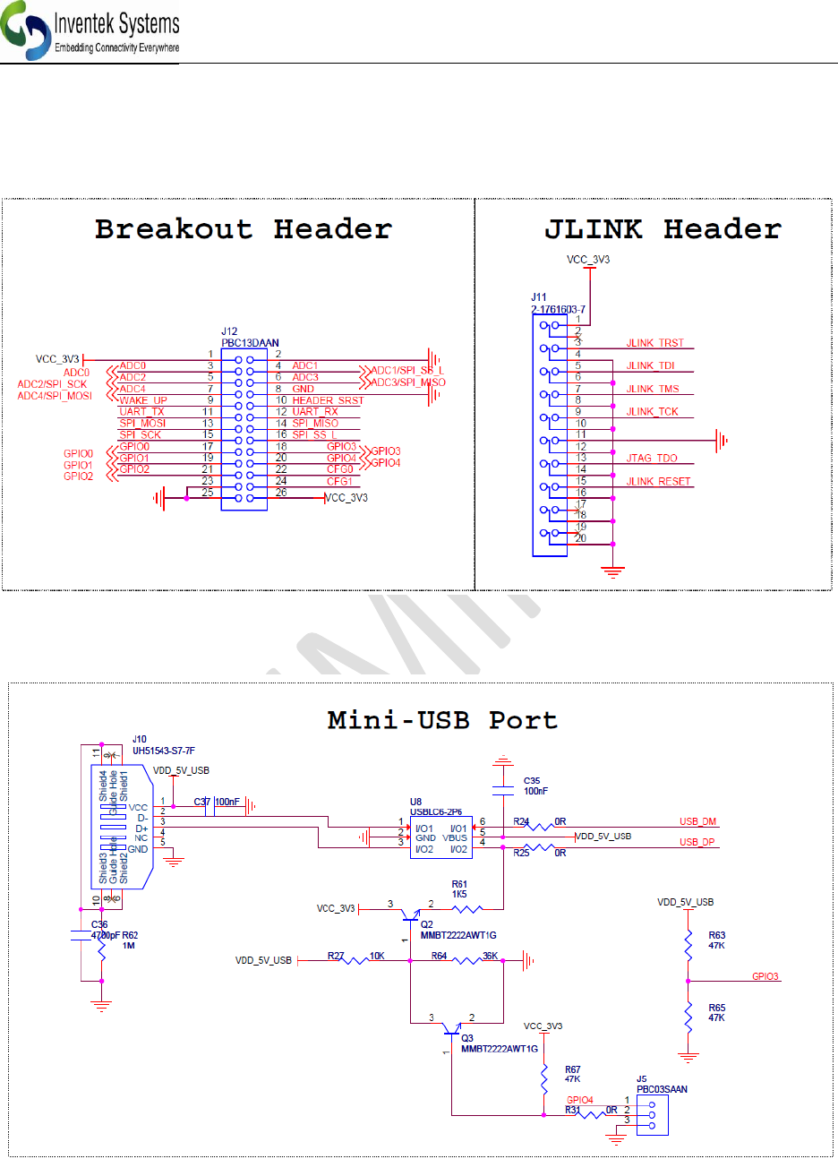
13.6 eS-WiFi Programming Options
13.7 eS-WiFi USB Direct Connection Option
ISM43362-M3X Product Specification
_____________________________________________________________________________________________
Inventek Systems DOC-DS-20023-2.1
33
14 Product Compliance Considerations
RoHS: Restriction of Hazardous Substances (RoHS) directive has come into force since
1st July 2006 all electronic products sold in the EU must be free of hazardous materials,
such as lead. Inventek is fully committed to being one of the first to introduce lead-free
GPS products while maintaining backwards compatibility and focusing on a
continuously high level of product and manufacturing quality.
EMI/EMC: The Inventek module design embeds EMI/EMC suppression features and
accommodations to allow for higher operational reliability in noisier (RF) environments
and easier integration compliance in host (OEM) applications.
FCC/CE: The module will be in compliance test for FCC/CE
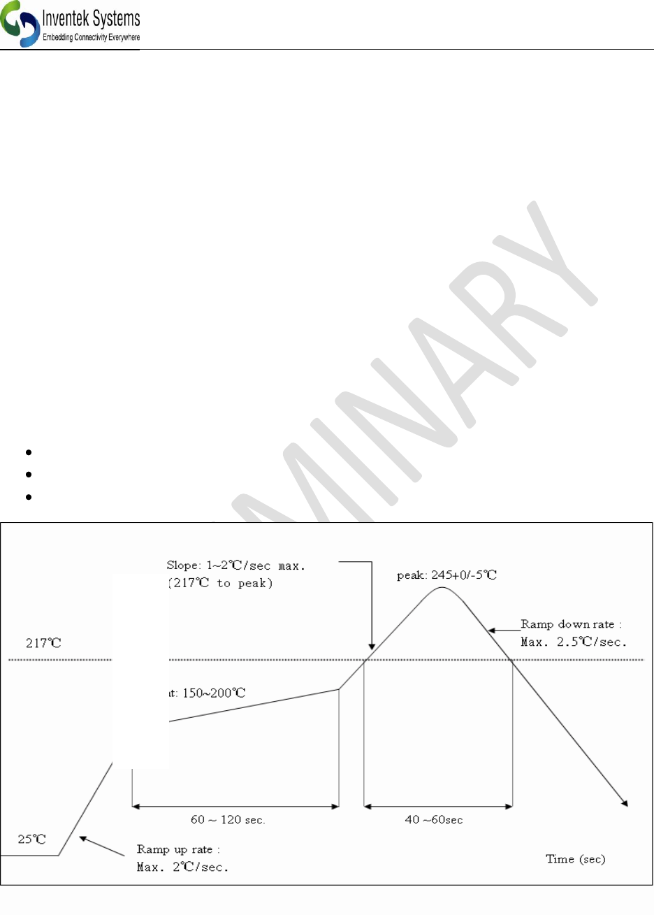
15 Reflow Profile
Reference the IPC/JEDEC standard.
Peak Temperature: <250°C
Number of Times: ≤2 times
ISM43362-M3X Product Specification
_____________________________________________________________________________________________
Inventek Systems DOC-DS-20023-2.1
34
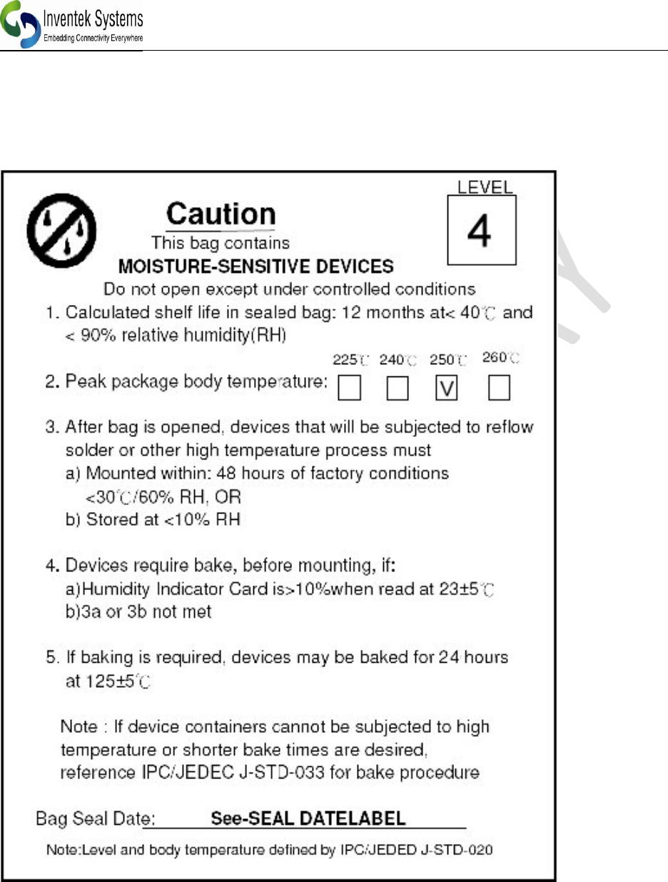
16 Packaging Information
16.1 MSL Level / Storage Condition

ISM43362-M3X Product Specification
_____________________________________________________________________________________________
Inventek Systems DOC-DS-20023-2.1
35
16.2 Device baking requirements prior to assembly
Boards must be baked prior to rework or assembly to avoid damaging moisture sensitive
components during localized reflow. The default bake cycles is 24 hours at 125C.
Maintaining proper control of moisture uptake in components is critical.
Before opening the shipping bag and attempting solder reflow, you should maintain a
minimal out-of-bag time and ensure the highest possible package reliability for the final
product.
Module’s Assembly Instructions
Board Placement: The ISM43362-M3G-L44 has an optional on board Wi-Fi antenna.
The board is designed to be a stuffing option. If you elect to use the on board antenna,
then board placement is critical in your system. Several key things to consider when
placing the module are:
Ensure that the antenna portion of the design is placed so that the antenna has
no ground plane under, above or near the antenna. Ideally, the antenna requires
clear sky for optimal performance. If you have shields or other material around
the antenna, please test for interference and loss of signal strength.
ISM43362-M3X Product Specification
_____________________________________________________________________________________________
Inventek Systems DOC-DS-20023-2.1
36
17 REVISION CONTROL
Document : ISM43362-M3X-L44
Wi-Fi module
External Release
DOC-DS-20023
Date
Author
Revision
Comment
8/15/2012
FMT
1.0
Preliminary
2/11/2013
FMT
1.1
Updated Ref.
Schematic
5/5/2013
FMT
2.0
Updated SPI
7/24/13
FMT
2.1
Added FCC, updated
Temp range
18 CONTACT INFORMATION
Inventek Systems
2 Republic Road
Billerica Ma, 01862
Tel: 978-667-1962
Sales@inventeksys.com
www.inventeksys.com
Inventek Systems reserves the right to make changes without further notice to any products or data herein to improve reliability,
function, or design. The information contained within is believed to be accurate and reliable. However Inventek Systems does not
assume any liability arising out of the application or use of this information, nor the application or use of any product or circuit
described herein, neither does it convey any license under its patent rights nor the rights of others.