Iradimed IRM00 NON-MAGNETIC PATIENT MONITOR User Manual LiNQ Operation Manual
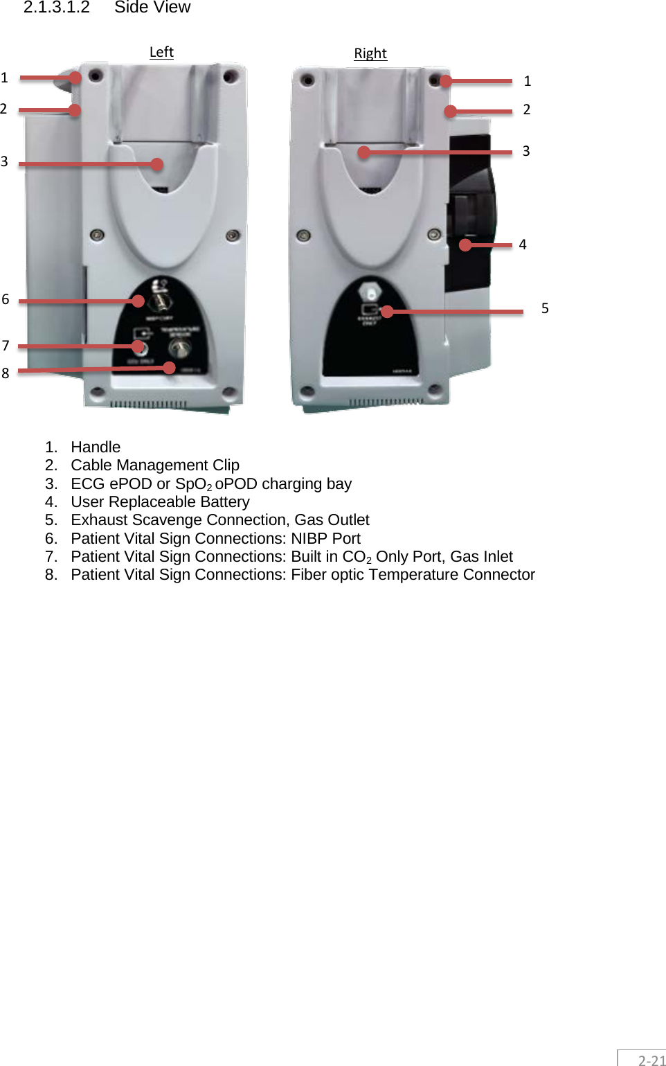
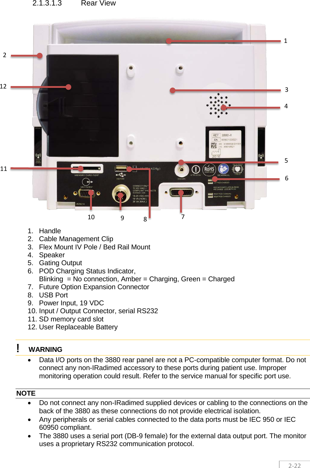
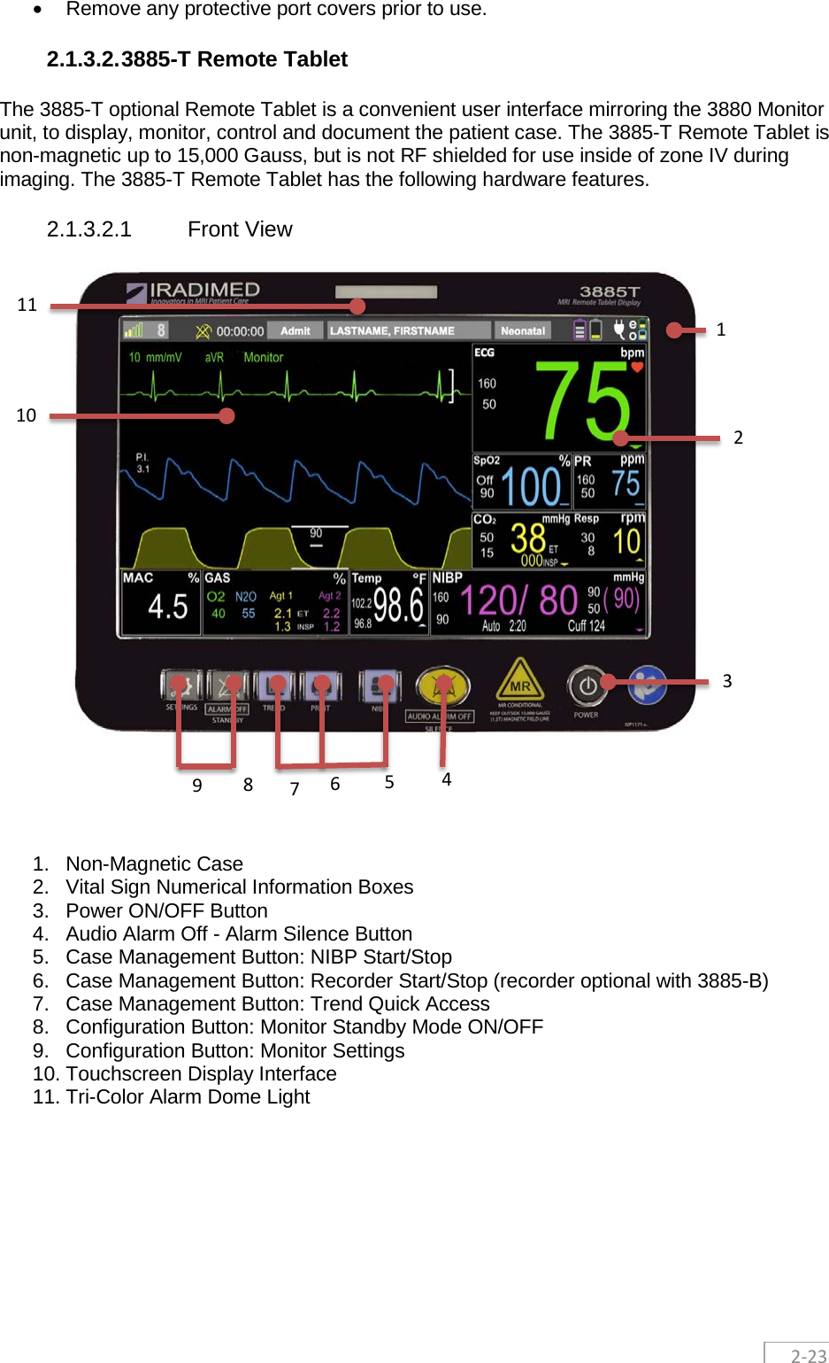
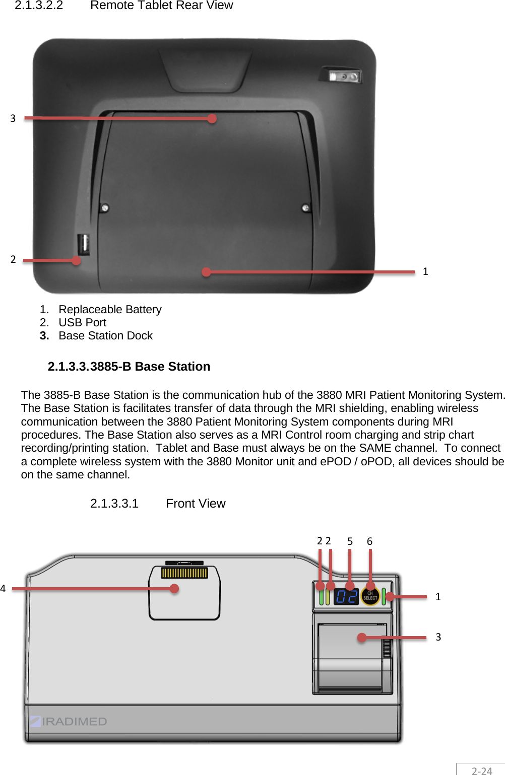
Iradimed Corporation NON-MAGNETIC PATIENT MONITOR LiNQ Operation Manual
Iradimed >
Contents
- 1. User Manual Part 1
- 2. User Manual Part 2
- 3. User Manual Part 3
User Manual Part 1

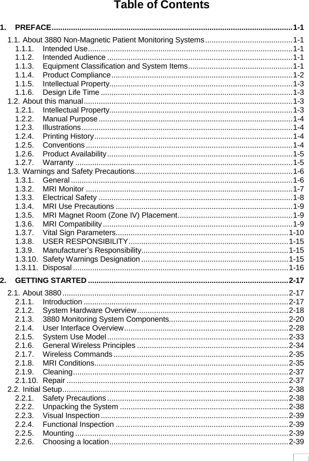
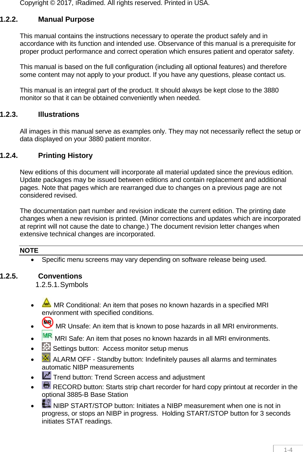
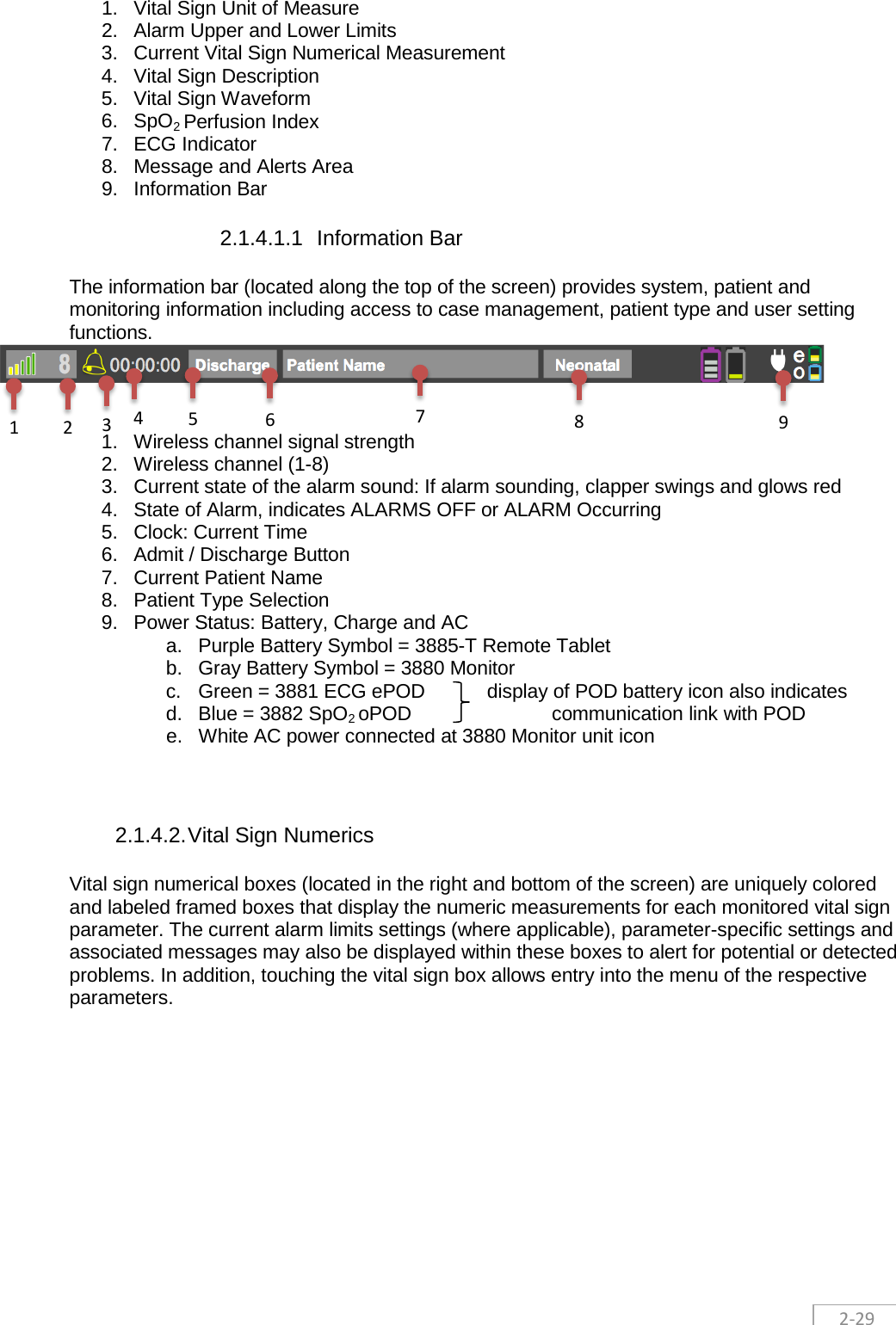
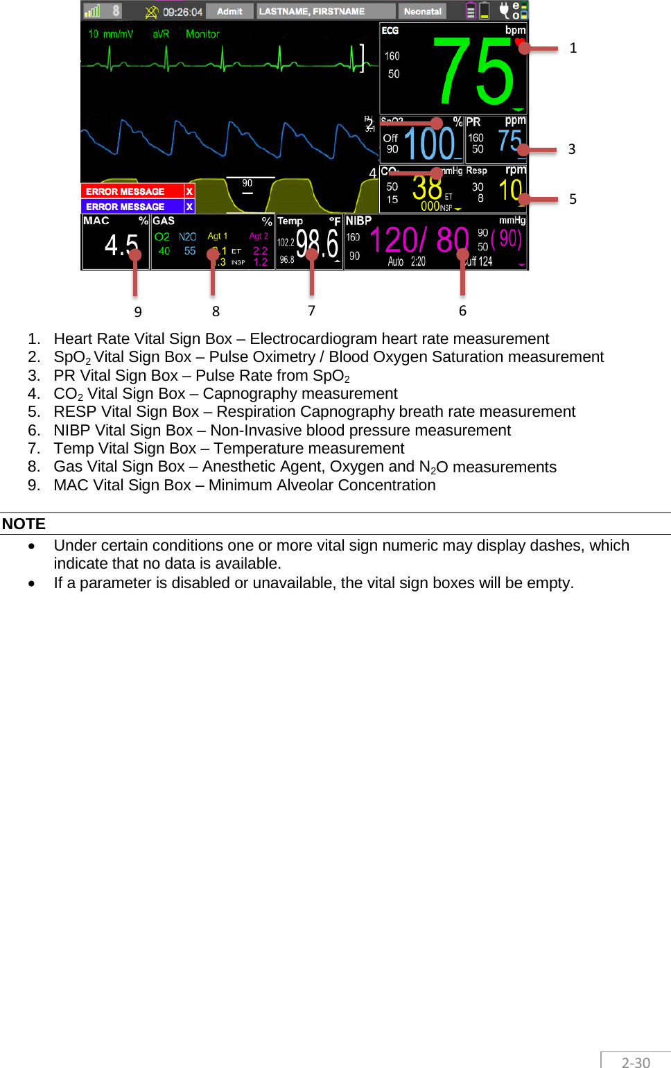
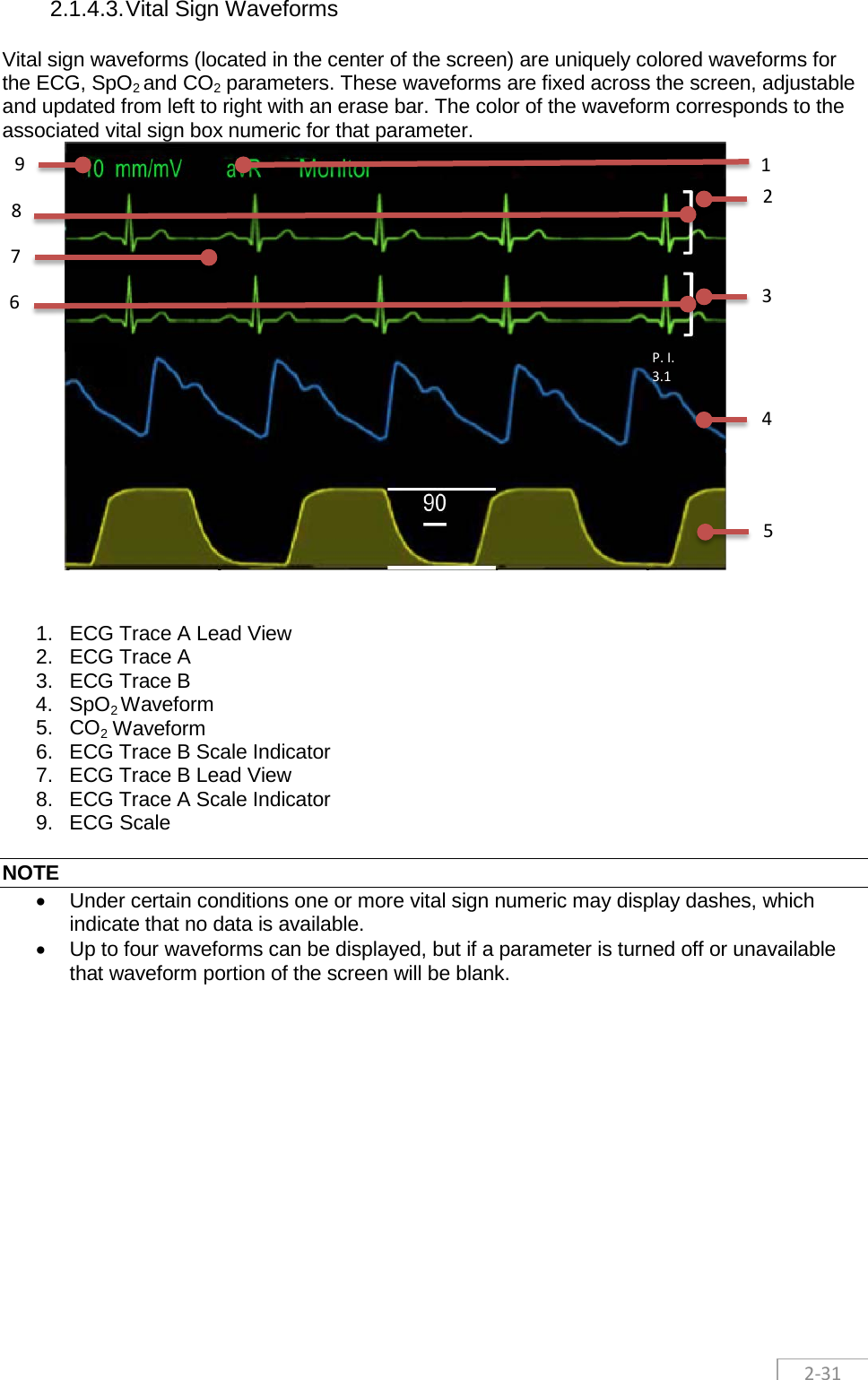
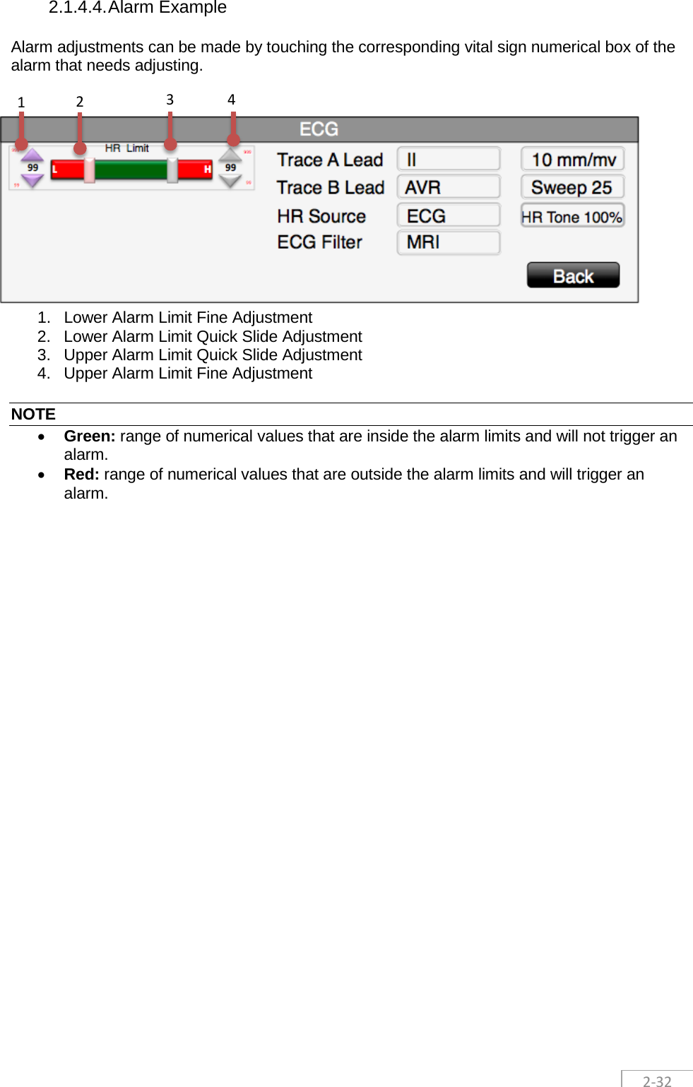
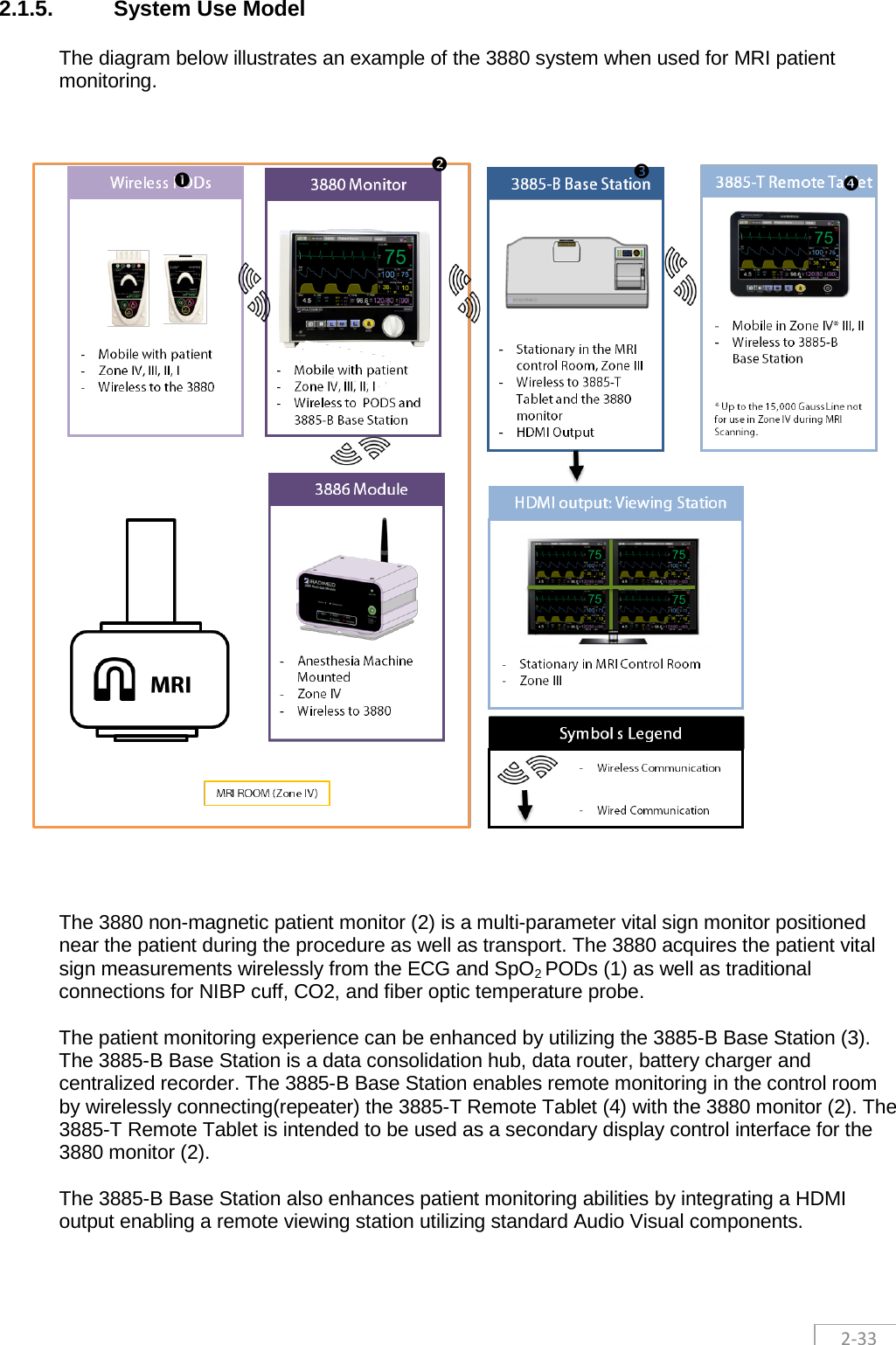
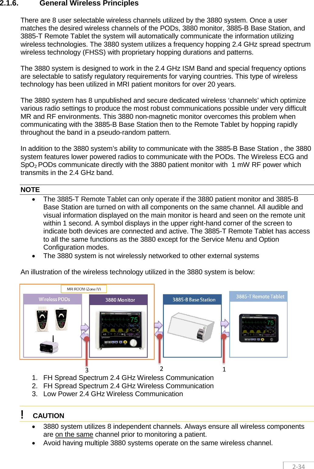
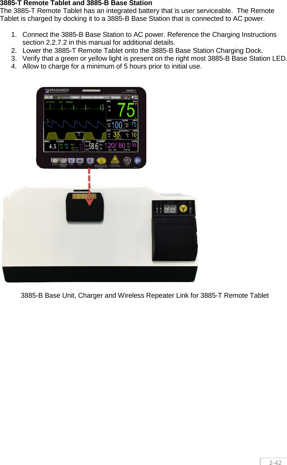
![2-20 2.1.3. 3880 Monitoring System Components 2.1.3.1. 3880 Multi-Parameter Monitor The 3880 system is a small and portable Non-Magnetic multi-parameter patient monitor designed for use when a large magnetic field such as a MRI system will be present during the patient’s care cycle. The 3880 system is used to acquire, process, and display all vital sign measurements during patient transport and during the MRI procedure. 2.1.3.1.1 Front View 1. Lightweight, Nonmagnetic Case 2. Vital Sign Numerical Information Boxes 3. Power ON/OFF Dial, Clockwise Monitor only ON, Center Off, Counter clockwise All On for Monitor and future Option Expansion Connector power on 4. Audio Alarm Off - Alarm Silence Button [AUDIO ALARM OFF] 5. Case Management Button: NIBP Start/Stop (Hold down to initiate STAT readings) 6. Case Management Button: Recorder Start/Stop (recorder optional with 3885-B) 7. Case Management Button: Trend Quick Access 8. Configuration Button: Monitor Standby [ALARM OFF] Mode ON/OFF 9. Configuration Button: Monitor Settings (Menus) 10. Mains Power/Charging LED Status 11. Touchscreen Display Interface 12. Tri-Color Alarm Dome Light 6 1 2 3 4 5 7 8 9 10 11 12](https://usermanual.wiki/Iradimed/IRM00.User-Manual-Part-1/User-Guide-3331597-Page-26.png)