Iradimed IRM00 NON-MAGNETIC PATIENT MONITOR User Manual LiNQ Operation Manual
Iradimed Corporation NON-MAGNETIC PATIENT MONITOR LiNQ Operation Manual
Iradimed >
Contents
- 1. User Manual Part 1
- 2. User Manual Part 2
- 3. User Manual Part 3
User Manual Part 2
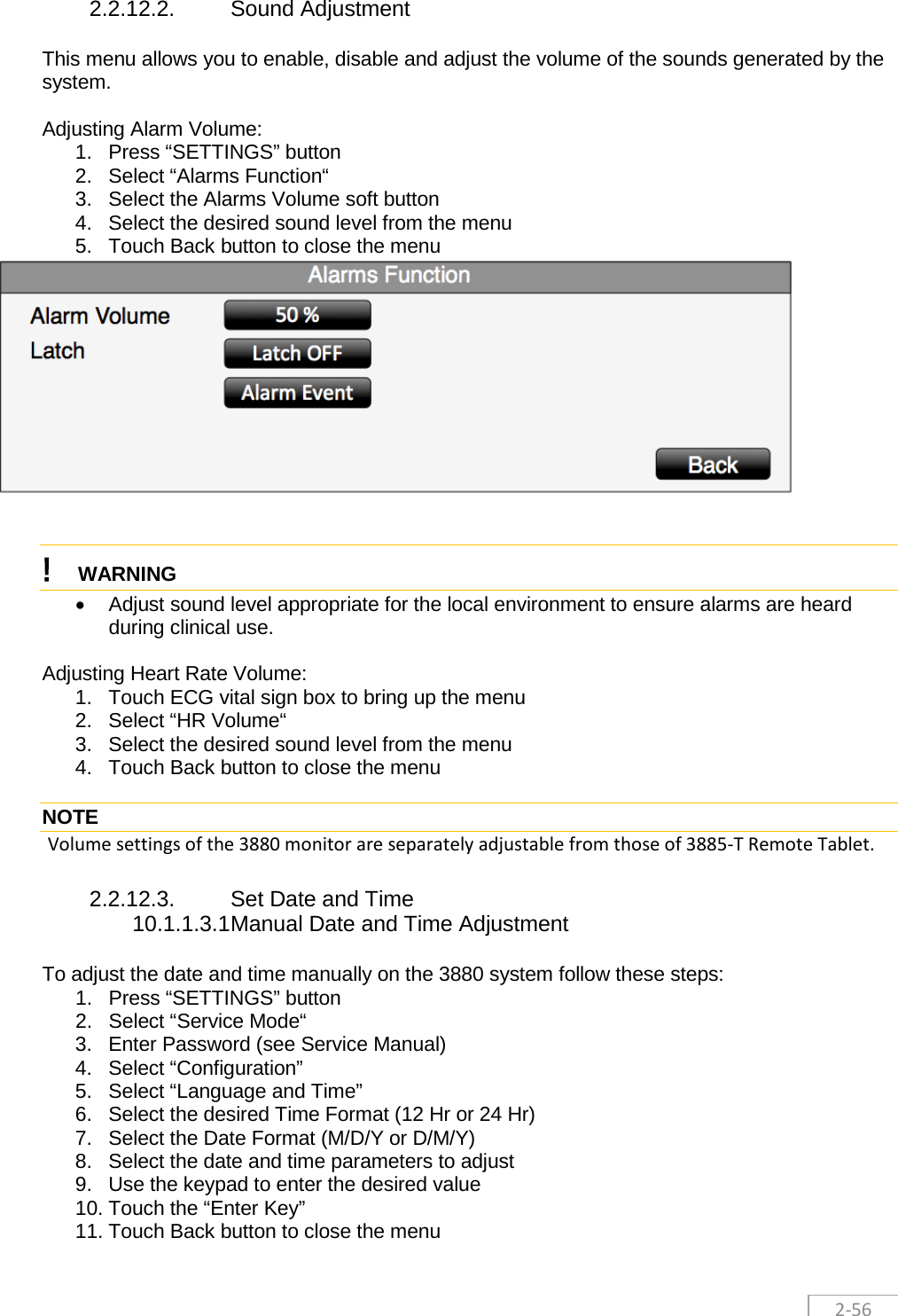
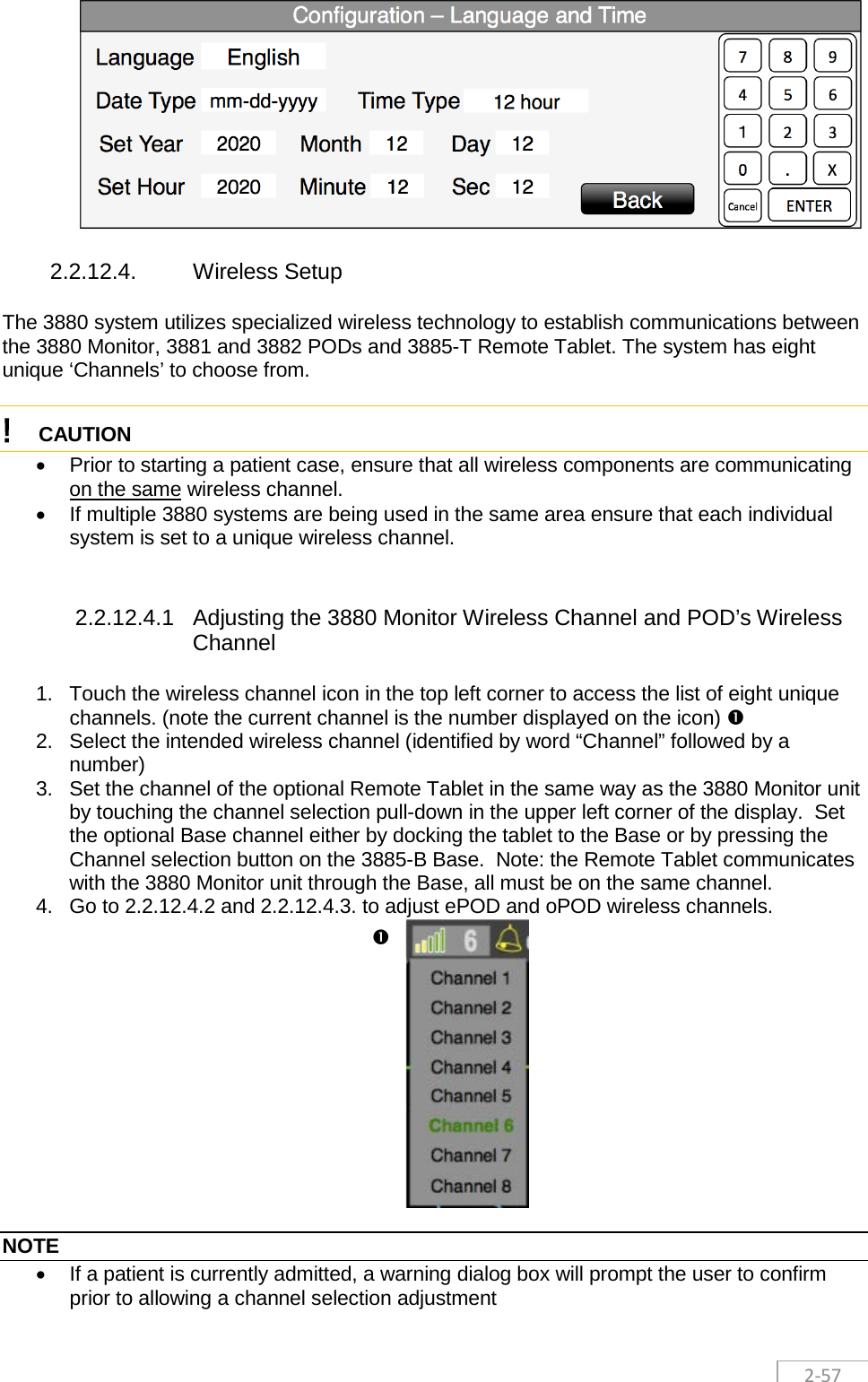
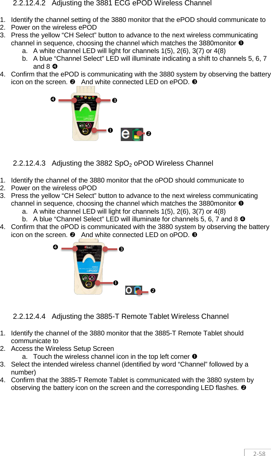
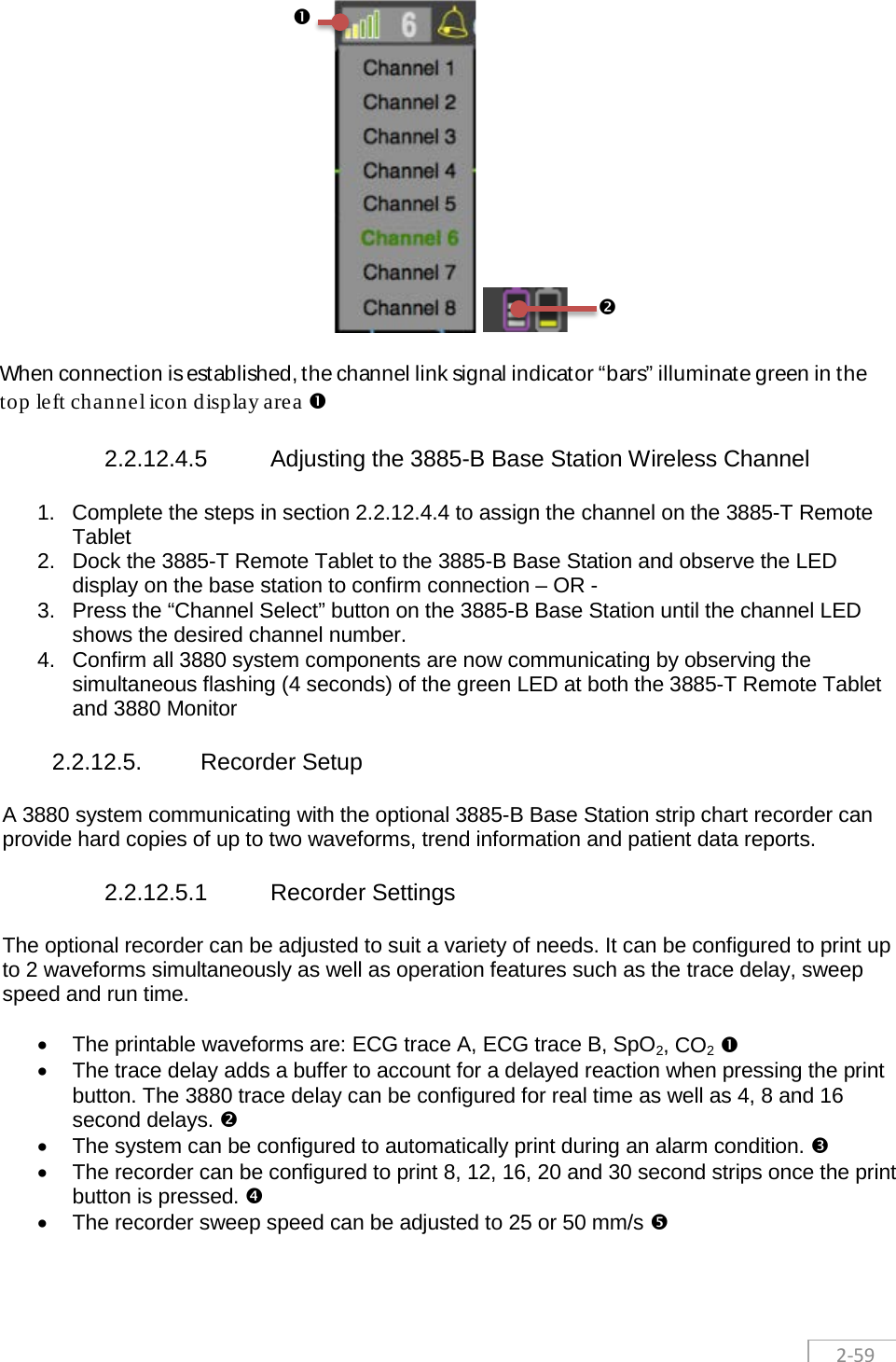
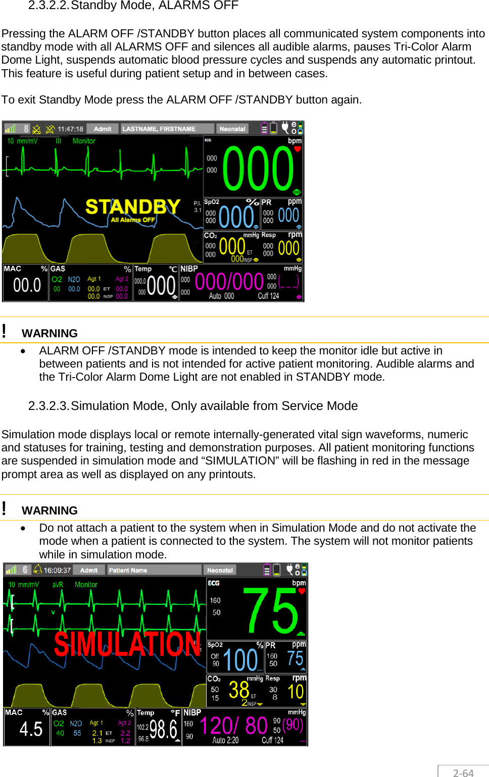
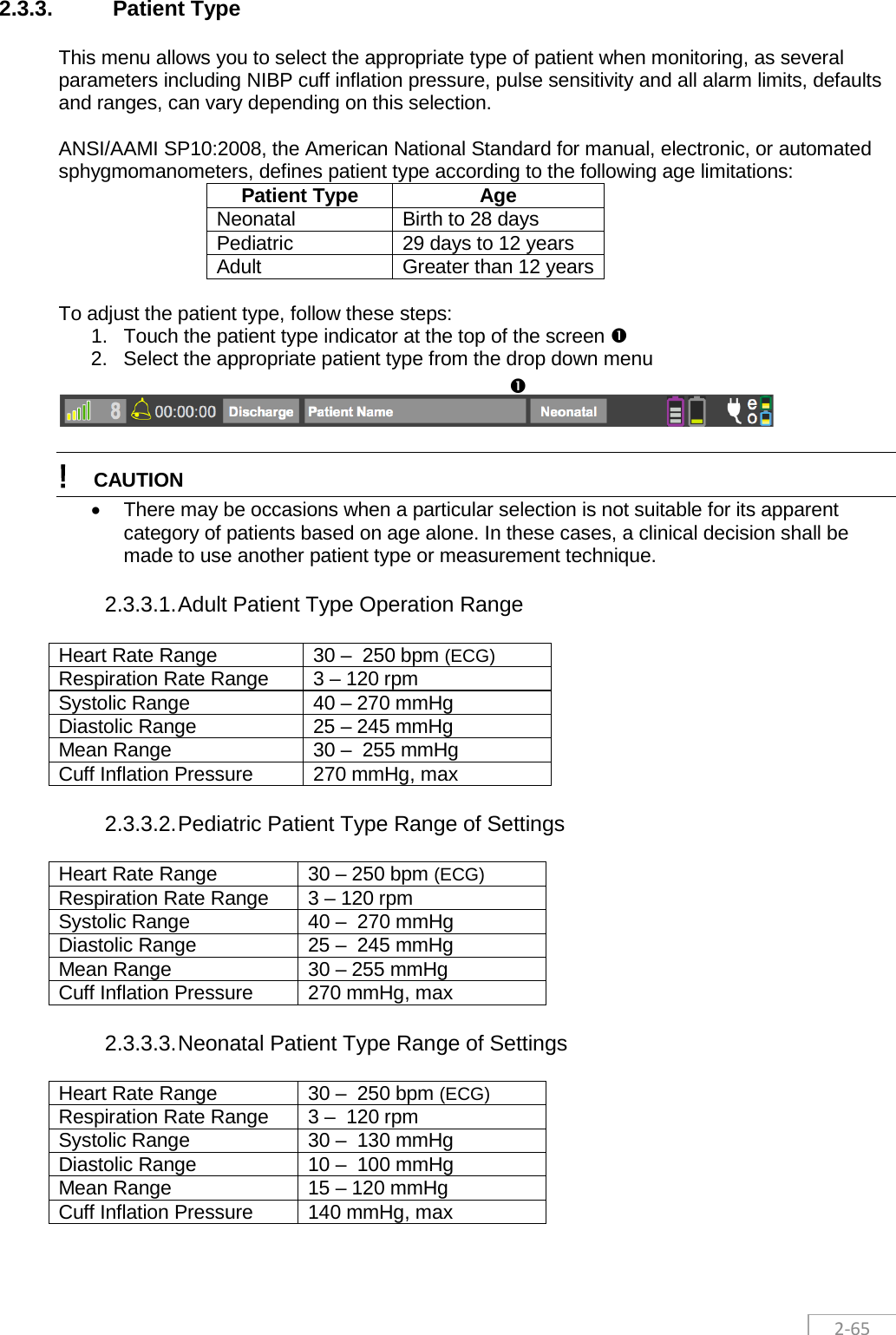
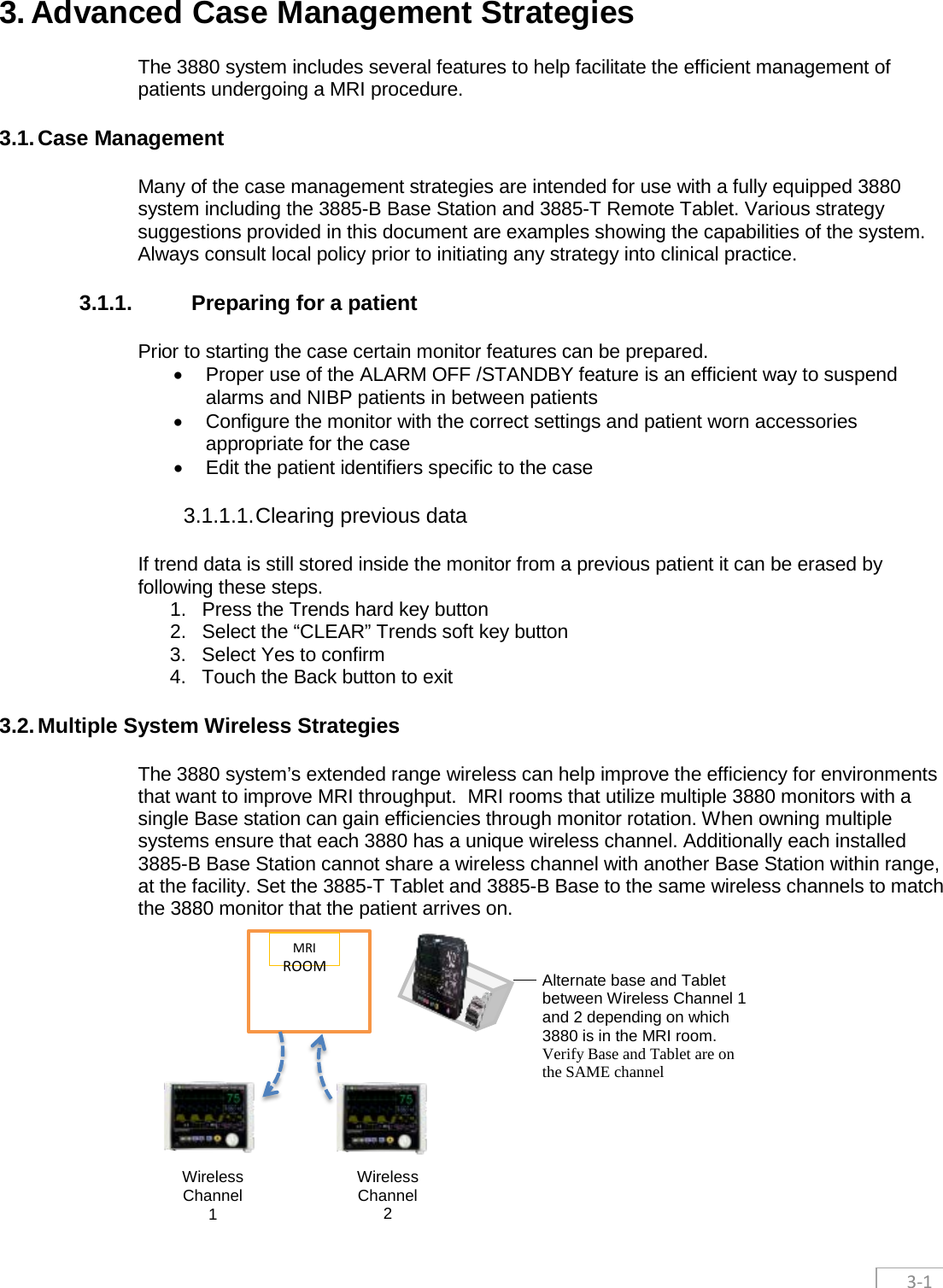
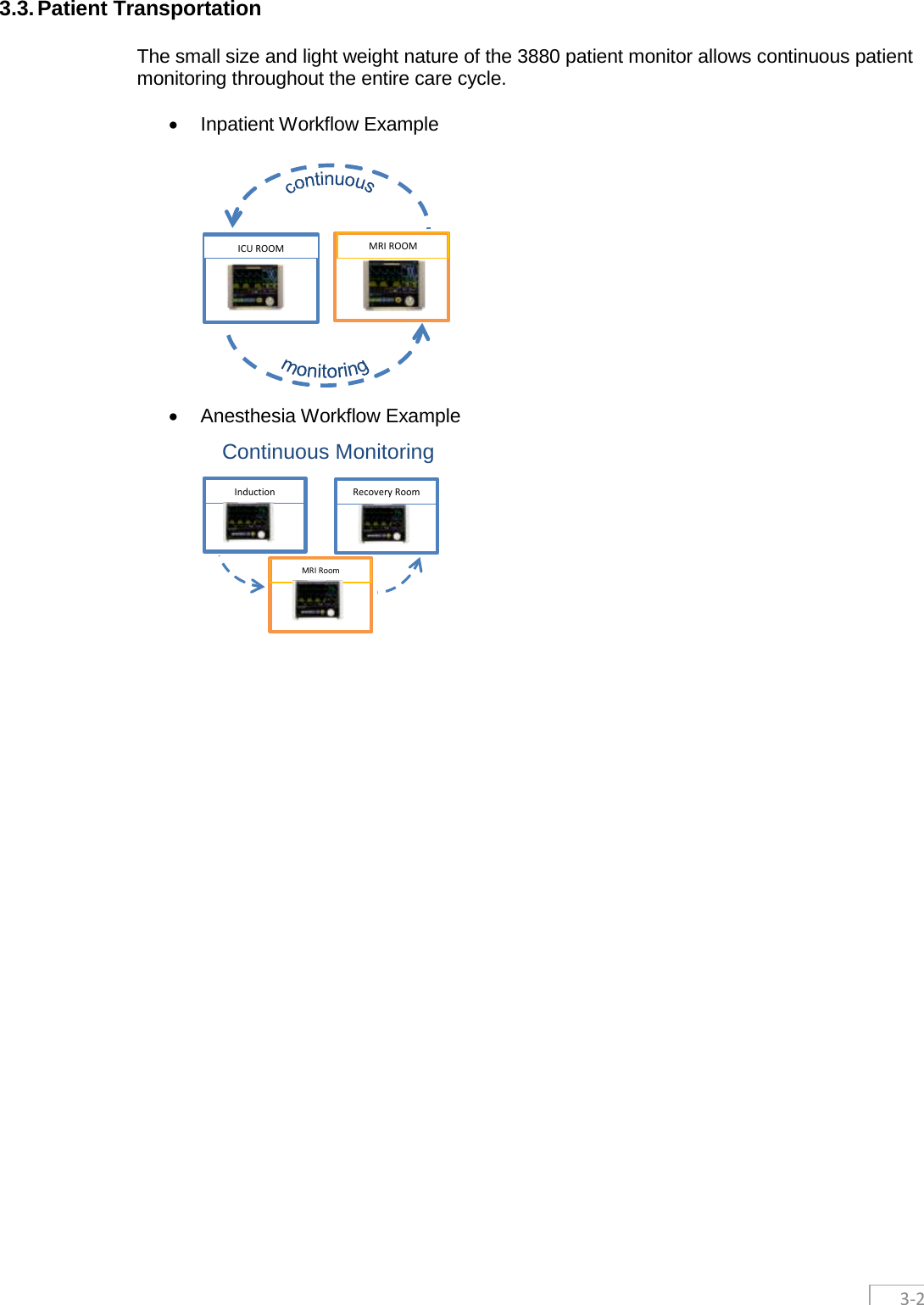
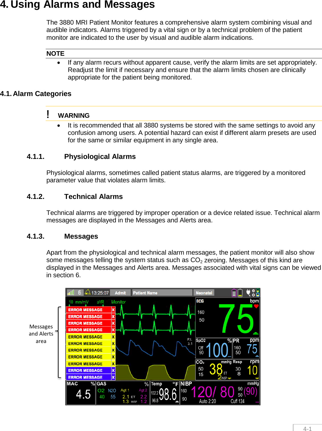
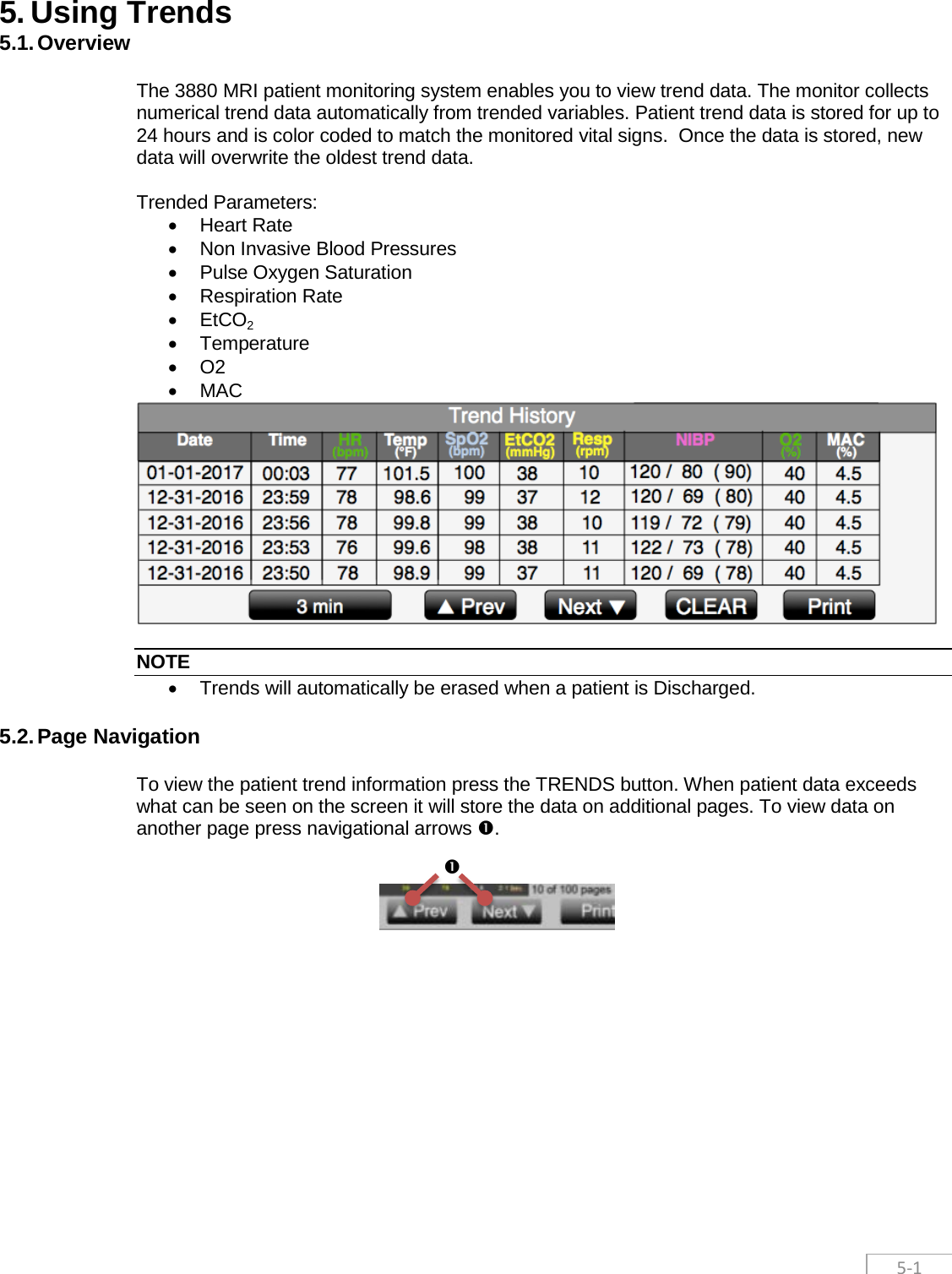
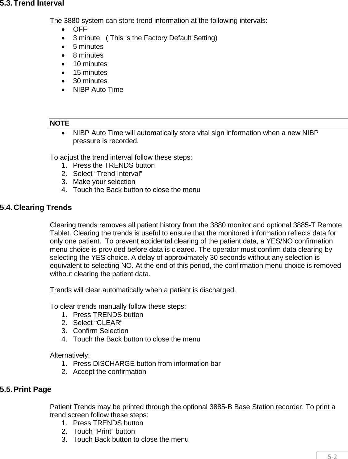
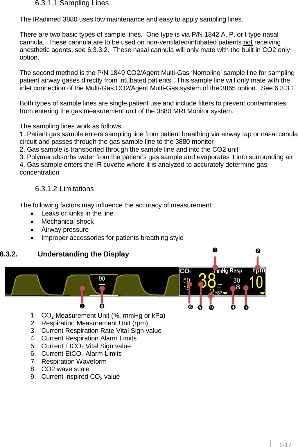
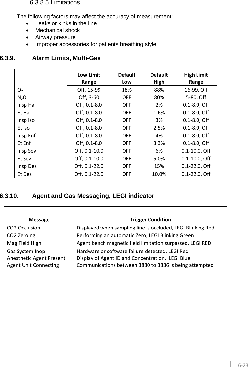
![4-2 4.1.3.1. Message System Overview The 3880 is equipped with a message area which automatically prioritizes and sorts messages in order of priority. When a message is present, it will show up in the lower left hand corner of the screen. Messages related to vital signs are color coded to priority and typically use a prefix denoting the associated vital sign before the message so the operators can quickly understand the context. The messages prefixes are as follows: • ECG : Electrocardiogram and HR related messages • SpO2: Pulse Oximetry related messages • CO2: Capnography, Gas and respiration related messages • Gas: Anesthetic agent related messages • NIBP: Non-Invasive blood pressure related messages • Temp: Temperature related messages 4.1.3.2. Multiple messages If there is an unacknowledged message displayed in the bottom left side of the screen when a subsequent message is generated the messages will stack vertically on top of each other. A maximum of 10 messages can be displayed at a time. Messages are arranged by priority, with higher priority messages on top as illustrated 4.1.3. 4.1.3.3. Message Priority Messages are color coded to quickly alert the operator to the priority of the alarm. The colors used for messages are as follows: • Red - High Priority messages indicate a severe situation that needs immediate response from the operator. • Yellow – Medium Priority messages indicate a serious situation that requires prompt operator attention. • Blue – Low Priority messages indicate situations that the operator needs to be aware of. 4.1.3.4. Acknowledgment and clearing of messages Messages will automatically clear and be removed from the screen when the event that generated the message is resolved. Users may also manually acknowledge the message and remove messages from the screen even if event is still present. Users can manually acknowledge and clear messages by touching the individual message from the message stack that they want to clear. Each message will display a [X] at the end as shown below as a visual indicator that user action is needed. By closing the message the user acknowledges the message and it will only reappear if the triggering condition is met again. 4.1.3.5. Exceeding Message Display Limit In the event there are multiple, simultaneous messages exceeding the displayable area of 10 stacked messages, a high priority flashing and sound will be triggered along with the high priority message in the eleventh and top position flashing “SEE MESSAGES!” This 11th and top position is reserved for only the “SEE MESSAGES” message. As users start to acknowledge and clear the messages, any yet to be displayed message will be appear according to priority in the newly created real-estate. NIBP Time Out X SEE MESSAGES! X](https://usermanual.wiki/Iradimed/IRM00.User-Manual-Part-2/User-Guide-3331600-Page-21.png)