Iradimed IRM00 NON-MAGNETIC PATIENT MONITOR User Manual LiNQ Operation Manual
Iradimed Corporation NON-MAGNETIC PATIENT MONITOR LiNQ Operation Manual
Iradimed >
Contents
- 1. User Manual Part 1
- 2. User Manual Part 2
- 3. User Manual Part 3
User Manual Part 2
2-50
align. The LEGI receptacle glows various colors to indicate status. See Section 6.3.10
4. Firmly insert the sampling line into the corresponding receptacle shown
5. Ensure that sampling line is secure into the monitor and not loose
6. Connect the appropriate airway adapter for the application as needed
7. Connect exhaust port to the scavenging system using part number 1846 as desired
! CAUTION
• Use only accessories specifically designed and approved for use with the IRadimed
3880 system. Refer to section 9 for a complete list of available accessories.
NOTE
• Allow the 3886 system to fully warm up (10 seconds) prior to connecting any sampling
circuits to the patient.
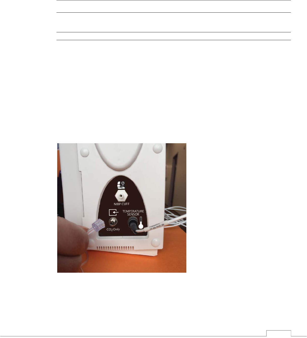
2.2.10.4. Internal CO2 Only Sampling Lines
The internally integrated CO2 only unit utilizes the CO2 only sample lines of Section 9.4
This integrated CO2 system is not for use with Anesthetic agents. The CO2 only
sample lines have a different mating connection than those for use with the 3886 Multi-
Gas Unit and so cannot be connected to the incorrect unit.
See Section 6.3.1.1 for further details of the gas sampling lines and their use. Connect
the CO2 only gas sampling line to the side of the 3880 Monitor Unit as shown below:
2-51
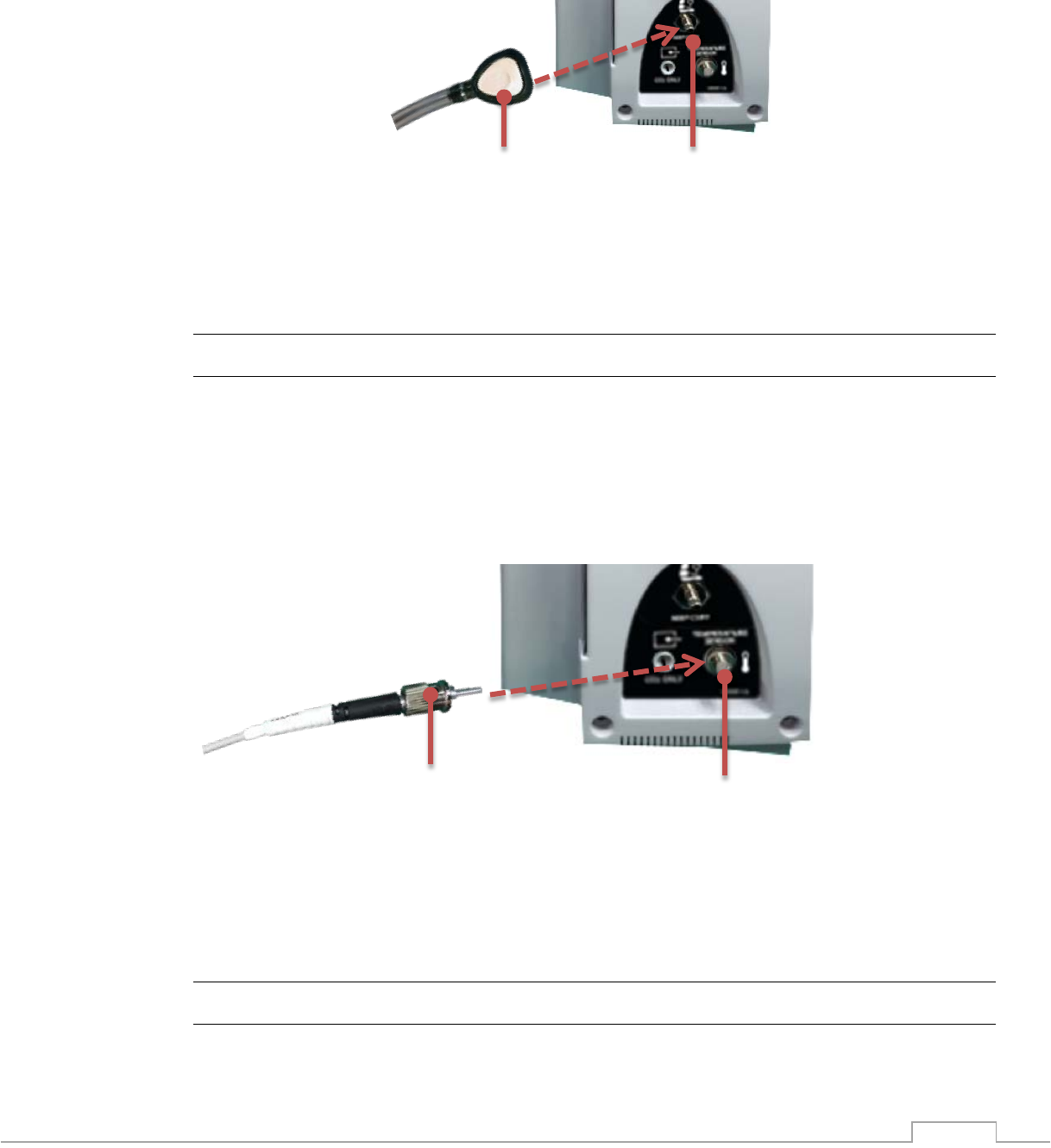
2.2.10.5. NIBP Lines
The NIBP feature utilizes the oscillometric method for measuring and displays systolic, diastolic,
and mean arterial pressures, and pulse rate.
To connect the NIBP Line:
1. Locate the NIBP line (1) and the NIBP receptacle on the 3880 monitor (2)
2. Position the NIBP line with the NIBP receptacle so they align
3. Firmly insert the NIBP line onto the corresponding receptacle ( 2) until the NIBP line is
secure, notice a snap when locked into place.
4. Ensure that NIBP line is secure into the monitor and not loose
! CAUTION
• Use only NIBP accessories specifically designed and authorized for use with the
IRadimed 3880 system. Refer to section 9.2 for a complete list of available accessories.
2.2.10.6. Temperature Fiber Optic Cable
The 3880 system can be configured with an optional temperature channel to continuously
measure either a patient’s surface or body temperature.
To connect the Temperature Cable:
1. Locate the temperature cable (1) and the temperature receptacle on the 3880 monitor
(2)
2. Position the temperature cable with the temperature receptacle (2) so they align
3. Gently insert the temperature cable into the corresponding receptacle and rotate the
outer locking ring clockwise until it stops.
4. Ensure that temperature cable is secure into the monitor and not loose.
! CAUTION
• The temperature sensors are constructed of fiber-optic glass and must always be
handled with care to prevent damage. Improper handling can result in inaccurate
readings.
1
2
1
2
1
2-52
• Use only temperature accessories specifically designed and authorized for use with the
IRadimed 3880 system. Refer to section 9.6 for a complete list of available accessories.
2.2.10.7. Additional Installation Options
Additional installation options such as those listed below may be suggested by your service
personnel or IRadimed representative to increase operator efficiency.
• Connection of 3885-B Base Station to an external monitor or external projector utilizing
the HDMI output.
2.2.11. User Interface
2.2.11.1. Powering On the System and Components
After the inspection and setup is finished and the 3880 system batteries are fully charged you
can switch the system on.
2.2.11.1.1 3880 System: Locate the power dial on the front of the monitor and rotate
it clockwise to the ON position.
NOTE
• An audible beep tone sounds and the Tri-Color Alarm Dome Light flashes yellow, red
and blue when the 3880 system is powered ON to confirm that the alarm system is
performing properly.
• If system fails to power on properly remove from use and refer to qualified service
personnel.
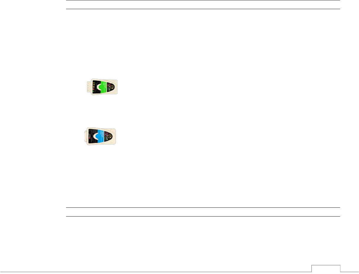
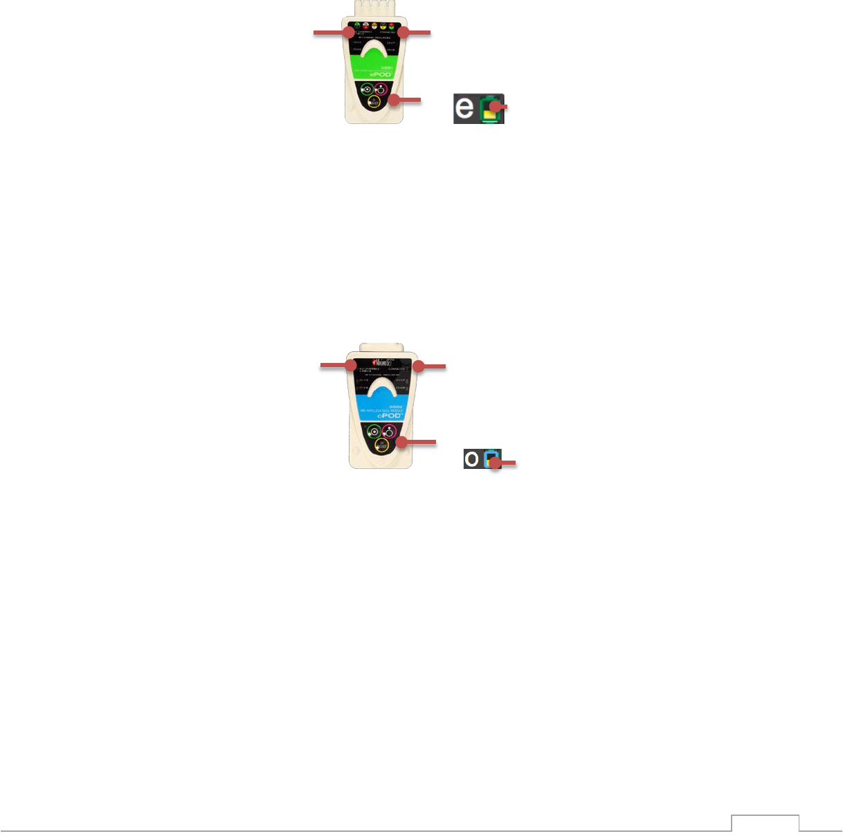
2.2.11.1.2 3881 ECG ePOD: Locate the power button and firmly press the power
button and observe the green LED power indicator.
2.2.11.1.3 3882 SpO2 oPOD: Locate the power button and firmly press the power
button and observe the green LED power indicator.
• Optional 3885-T Remote Tablet and 3885-B Base Station:
1. Locate the power button on the rear of the 3885-B Base Station and press into the ON
position.
2. Locate the power button on the 3885-T Remote Tablet and firmly press the power
button, hold approximately 3 seconds to turn on or off.
NOTE
• An audible beep tone sounds and the Tri-Color Alarm Dome Light flashes yellow, red
and blue when the 3880 system is powered ON to confirm that the alarm system is
performing properly.
2-53
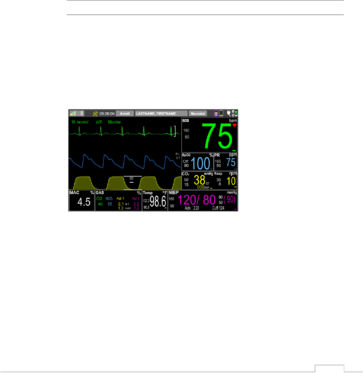
2.2.11.2. Displayed Information
The 3880 monitor and 3885-T Remote Tablet display the following types of information.
Reference section 2.1 for images.
• Vital Sign Waveforms
• Vital Sign Numerics
• Case Management data
• System Status
• Messages Alerts area
2.2.11.3. Navigation
The 3880 monitor and 3885-T Remote Tablet utilize a combination of hard keys and touch
screen soft keys to operate.
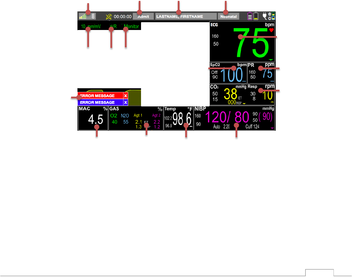
2.2.11.4. Using Screen Touch Points
1. Wireless channel selection and signal strength
2. Patient admit / discharge button
3. Patient identifiers (LAST Name, FIRST Name) adjustment
4. Patient type adjustment (Adult, Pediatric, Neonatal)
5. Display area and menu access for ECG
6. Display area and menu access for pulse rate
7. Display area and menu access for respiration rate and CO2
8. Display area and menu access for NIBP
9. Display area and menu access for temperature
10. Display area and menu access for gases
11. Display area and menu access for MAC
12. Display area and menu access for SpO2
13. ECG Filter Quick Selection
14. ECG Lead Quick Selection
15. ECG Scale Quick Selection
1
2
3
4
5
6
7
9
10
8
14
15
16
11
13
12
2-54
16. Messages and Alerts area
NOTE
• If the touchscreen is not responsive or blank, remove from use and refer the monitor to
qualified service personnel.
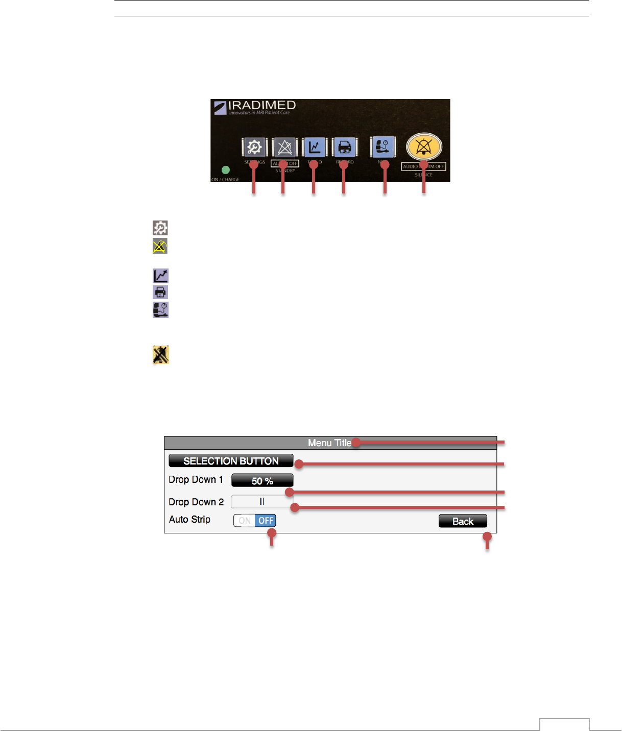
2.2.11.5 Using Control Switch Hard Keys
1. SETTINGS: Access monitor setup menus
2. ALARM OFF - Standby button: Indefinitely pauses all alarms and terminates
automatic NIBP measurements
3. TRENDS: Trend Screen access and adjustment
4. PRINT: Prints to optional recorder in the Base Station
5. NIBP START/STOP: Initiates a NIBP measurement when one is not in progress, or
stops an NIBP in progress. Holding START/STOP button for 3 seconds initiates STAT
readings.
6. AUDIO ALARM OFF – Alarm Silence button: multi-function audible alarm control,
resets sounding of alarm, pauses for 120 seconds the alarm sound, or re-enables alarm
sound capability.
2.2.11.6 Using Menus (Touch Screen controls)
1. Menu Title: Description correlating the menu choices
2. SELECTION BUTTON: Touching will make a desired selection or open up a new menu
3. DROP DOWN BUTTON 1: Touching will enable a pop up menu to make a selection
from multiple choices
4. DROP DOWN BUTTON 2: Touching will enable a pop up menu to make a selection
from multiple choices
5. BACK BUTTON: Closes menu and returns user to previous menu or main monitoring
screen
6. TOGGLE SWITCH: Touching will toggle the desired selection between Enabled and
Disabled
1
2
3
4
5
6
1
2
3
4
5
6
2-55
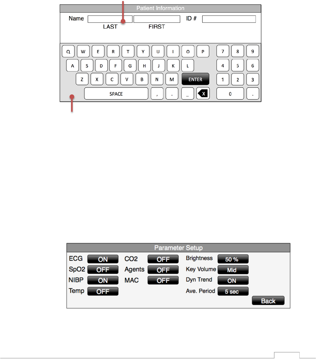
2.2.11.7 Virtual Keyboard / Keypad
1. Select the desired field to input text by touching that area
2. Input desired text by utilizing the on screen virtual keyboard
2.2.12. Setup Menu Overview
2.2.12.1. Parameters
The Parameters menu contains selections that allow users to customize and control functions
and settings used to measure and monitor vital signs.
To enable or disable parameters:
1. Press the SETTINGS button
2. Select “Parameter Setup”
3. Touch corresponding “ON/OFF” toggle to configure system parameters as ON (active)
or OFF (not used)
4. Brightness – provides a drop down with four display brightness settings: 25%, 50%,
75%, 100%
5. Key Volume – provides a drop down with three levels for the key touch “click” sound.
6. Touch Back button when complete to close menus
1
2
2-56
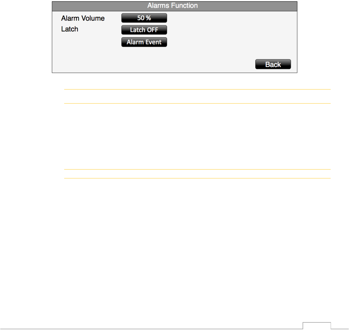
2.2.12.2. Sound Adjustment
This menu allows you to enable, disable and adjust the volume of the sounds generated by the
system.
Adjusting Alarm Volume:
1. Press “SETTINGS” button
2. Select “Alarms Function“
3. Select the Alarms Volume soft button
4. Select the desired sound level from the menu
5. Touch Back button to close the menu
! WARNING
• Adjust sound level appropriate for the local environment to ensure alarms are heard
during clinical use.
Adjusting Heart Rate Volume:
1. Touch ECG vital sign box to bring up the menu
2. Select “HR Volume“
3. Select the desired sound level from the menu
4. Touch Back button to close the menu
NOTE
Volume settings of the 3880 monitor are separately adjustable from those of 3885-T Remote Tablet.
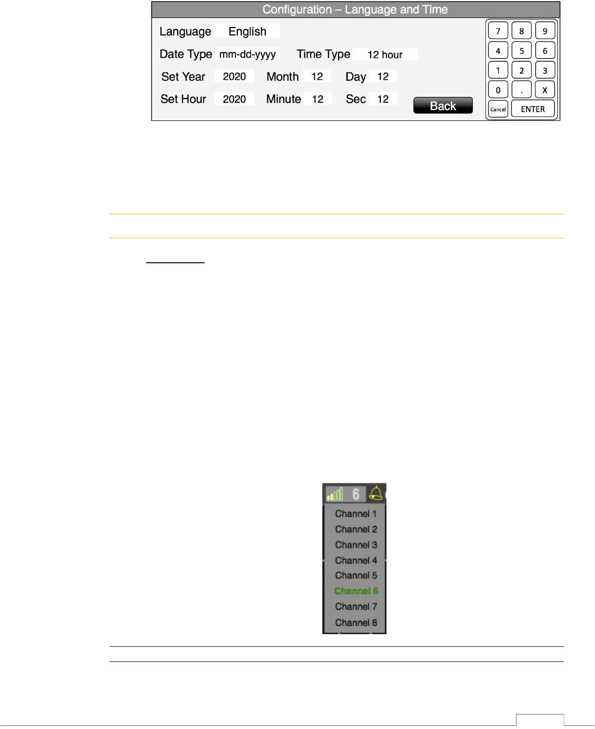
2.2.12.3. Set Date and Time
10.1.1.3.1 Manual Date and Time Adjustment
To adjust the date and time manually on the 3880 system follow these steps:
1. Press “SETTINGS” button
2. Select “Service Mode“
3. Enter Password (see Service Manual)
4. Select “Configuration”
5. Select “Language and Time”
6. Select the desired Time Format (12 Hr or 24 Hr)
7. Select the Date Format (M/D/Y or D/M/Y)
8. Select the date and time parameters to adjust
9. Use the keypad to enter the desired value
10. Touch the “Enter Key”
11. Touch Back button to close the menu
2-57
2.2.12.4. Wireless Setup
The 3880 system utilizes specialized wireless technology to establish communications between
the 3880 Monitor, 3881 and 3882 PODs and 3885-T Remote Tablet. The system has eight
unique ‘Channels’ to choose from.
! CAUTION
• Prior to starting a patient case, ensure that all wireless components are communicating
on the same wireless channel.
• If multiple 3880 systems are being used in the same area ensure that each individual
system is set to a unique wireless channel.
2.2.12.4.1 Adjusting the 3880 Monitor Wireless Channel and POD’s Wireless
Channel
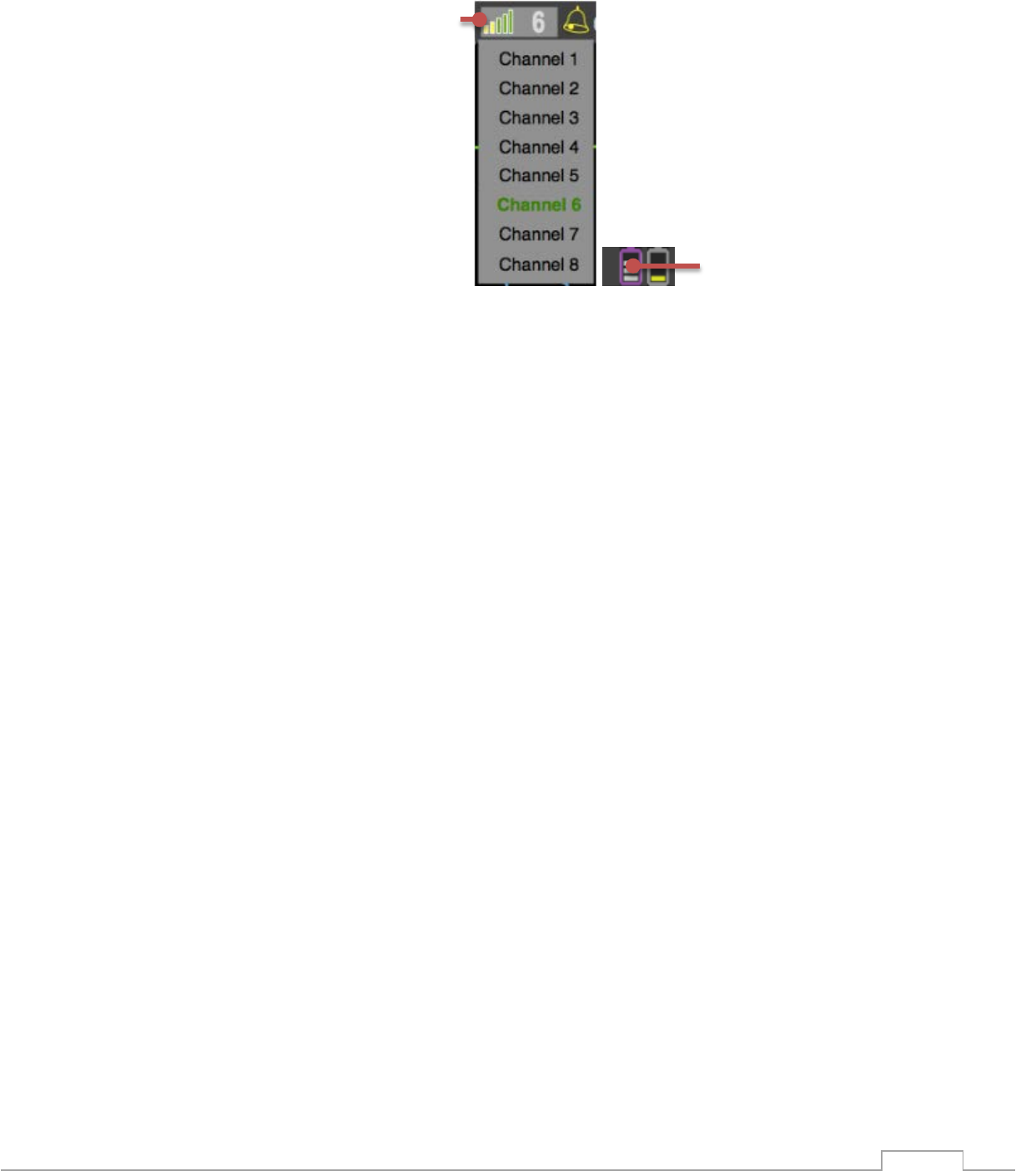
1. Touch the wireless channel icon in the top left corner to access the list of eight unique
channels. (note the current channel is the number displayed on the icon)
2. Select the intended wireless channel (identified by word “Channel” followed by a
number)
3. Set the channel of the optional Remote Tablet in the same way as the 3880 Monitor unit
by touching the channel selection pull-down in the upper left corner of the display. Set
the optional Base channel either by docking the tablet to the Base or by pressing the
Channel selection button on the 3885-B Base. Note: the Remote Tablet communicates
with the 3880 Monitor unit through the Base, all must be on the same channel.
4. Go to 2.2.12.4.2 and 2.2.12.4.3. to adjust ePOD and oPOD wireless channels.
NOTE
• If a patient is currently admitted, a warning dialog box will prompt the user to confirm
prior to allowing a channel selection adjustment
2-58
2.2.12.4.2 Adjusting the 3881 ECG ePOD Wireless Channel
1. Identify the channel setting of the 3880 monitor that the ePOD should communicate to
2. Power on the wireless ePOD
3. Press the yellow “CH Select” button to advance to the next wireless communicating
channel in sequence, choosing the channel which matches the 3880monitor
a. A white channel LED will light for channels 1(5), 2(6), 3(7) or 4(8)
b. A blue “Channel Select” LED will illuminate indicating a shift to channels 5, 6, 7
and 8
4. Confirm that the ePOD is communicating with the 3880 system by observing the battery
icon on the screen. And white connected LED on ePOD.
2.2.12.4.3 Adjusting the 3882 SpO2 oPOD Wireless Channel
1. Identify the channel of the 3880 monitor that the oPOD should communicate to
2. Power on the wireless oPOD
3. Press the yellow “CH Select” button to advance to the next wireless communicating
channel in sequence, choosing the channel which matches the 3880monitor
a. A white channel LED will light for channels 1(5), 2(6), 3(7) or 4(8)
b. A blue “Channel Select” LED will illuminate for channels 5, 6, 7 and 8
4. Confirm that the oPOD is communicated with the 3880 system by observing the battery
icon on the screen. And white connected LED on oPOD.
2.2.12.4.4 Adjusting the 3885-T Remote Tablet Wireless Channel
1. Identify the channel of the 3880 monitor that the 3885-T Remote Tablet should
communicate to
2. Access the Wireless Setup Screen
a. Touch the wireless channel icon in the top left corner
3. Select the intended wireless channel (identified by word “Channel” followed by a
number)
4. Confirm that the 3885-T Remote Tablet is communicated with the 3880 system by
observing the battery icon on the screen and the corresponding LED flashes.
2-59
When connection is established, the channel link signal indicator “bars” illuminate green in the
top left channel icon display area
2.2.12.4.5 Adjusting the 3885-B Base Station Wireless Channel
1. Complete the steps in section 2.2.12.4.4 to assign the channel on the 3885-T Remote
Tablet
2. Dock the 3885-T Remote Tablet to the 3885-B Base Station and observe the LED
display on the base station to confirm connection – OR -
3. Press the “Channel Select” button on the 3885-B Base Station until the channel LED
shows the desired channel number.
4. Confirm all 3880 system components are now communicating by observing the
simultaneous flashing (4 seconds) of the green LED at both the 3885-T Remote Tablet
and 3880 Monitor
2.2.12.5. Recorder Setup
A 3880 system communicating with the optional 3885-B Base Station strip chart recorder can
provide hard copies of up to two waveforms, trend information and patient data reports.
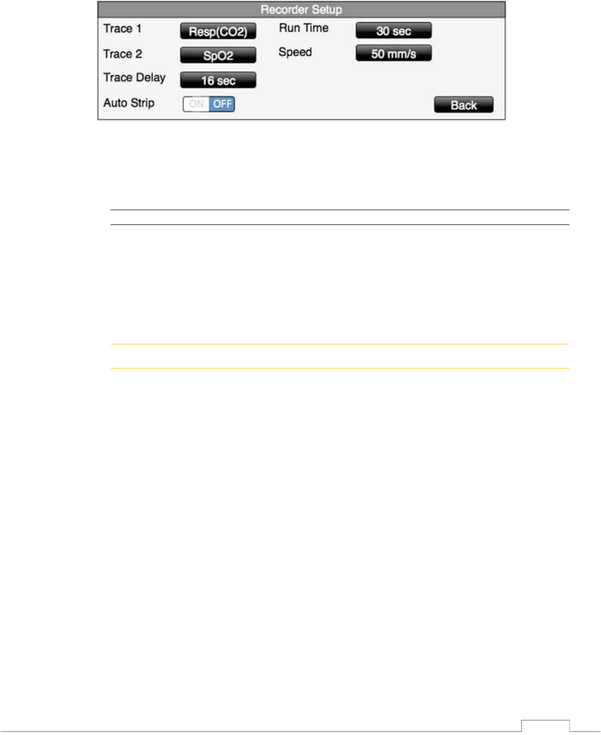
2.2.12.5.1 Recorder Settings
The optional recorder can be adjusted to suit a variety of needs. It can be configured to print up
to 2 waveforms simultaneously as well as operation features such as the trace delay, sweep
speed and run time.
• The printable waveforms are: ECG trace A, ECG trace B, SpO2, CO2
• The trace delay adds a buffer to account for a delayed reaction when pressing the print
button. The 3880 trace delay can be configured for real time as well as 4, 8 and 16
second delays.
• The system can be configured to automatically print during an alarm condition.
• The recorder can be configured to print 8, 12, 16, 20 and 30 second strips once the print
button is pressed.
• The recorder sweep speed can be adjusted to 25 or 50 mm/s
2-60
To adjust the recorder settings follow these steps:
1. Press “SETTINGS” button
2. Select “Recorder Setup”
3. Make adjustments
4. Touch Back button to close the menu
NOTE
• Refer to section 7 for available choices for setting up the Recorder.
2.2.12.6. Alarm Setup
Physiological and technical alarms are reported visually and audibly by the 3880 system. Alarm
limit settings have a lower limit setting and an upper limit setting. A physiological alarm
condition arises when the current numeric value for a vital sign falls outside the either of those
settings for a monitored parameter.
! WARNING
• Always respond promptly to any alarm condition.
• You should verify that the alarm preset is appropriate prior to starting a case.
• If a problem with the alarm tone, messaging system or Tri-Color Alarm Dome Light is
suspected, stop use and contact qualified service personnel for evaluation.
2.2.12.6.1 Vital Sign Alarm Adjustment
A single vital sign alarm can be quickly adjusted from the main monitoring screen. To adjust an
alarm directly from the running screen follow these steps:
1. Touch the vital sign box containing the vital sign you want to adjust
2. Use the arrows or Quick Slide adjuster to enter the upper and lower Alarm Limits
3. Touch the Back button to close the menu
4. Repeat steps 3-5 for each additional vital sign to adjust
2.2.12.6.2 Alarm Latching Settings
The factory default setting for all alarms is unlatched. When a user enables latched alarms the
alarm messages stay on the screen even if the initial alarm condition is resolved. To clear the
message field of the resolved alarm messages and to clear the audible beep, press the Alarms
Silence key once.
To adjust the Alarm Latching settings follow these steps:
1. Press the “SETTINGS” button
2. Select “Alarms Function”
3. Select “Latching” or “Unlatched”
4. Touch Back button to close the menu

2-61
2.2.12.7. Store/Recall of User Setup
This feature allows you to store multiple user setups and to select one for a default power up
setting. Storage of different procedures, patient types and users are available by customizing
the following:
• Alarms
1. Minimum and Maximum Limit Values, not including
‘OFF’
2. Latched or unlatched
3. Alarm volume level, not including OFF or 0 sound
• Patient Type
1. Adult
2. Pediatric
3. Neonatal
• SpO2
1. SpO2 parameter on or off
2. Sweep Rate
• ECG
1. ECG Lead 1 on or off, Lead 2 OFF
2. Selected lead
3. Scale setting
4. Sweep Rate
5. Filter mode
6. QRS tone volume
7. Heart rate source
• NIBP
1. NIBP parameter on or off
2. Automatic time interval
• Temperature
1. Temperature parameter on or off
2. Unit
• CO2
1. CO2 and Respiration on or off
2. Scale
3. Unit
4. Resp Source
5. Sweep Rate
• Trends
1. Interval
• Recorder
1. Selected waveform(s)
2. Trace Delay
3. Speed
4. Run Time
5. Auto Strip
• Display Brightness
• Dynamic Trend
1. ON / OFF
2. Ave. Period
• MAC
FACTORY DEFAULT
Unlatched
100 %
Adult
ON
25
ON (Lead 1 only)
II
10
25
MRI
50 %
ECG
ON
Off / Manual
OFF
C°
OFF
40
mmHg
CO2
6.25
ON
3 min
ECG
8 sec
25
30 sec
OFF
75 %
OFF
5 min
OFF
2-62
NOTE
• Wireless Channel cannot be stored under a user setting. The 3880 system components
will power on with the last channel that was used. See 2.2.12.9 Auto settings Memory.
• Settings modified during use will be retained and used for short power on to off to on
cycle of < 1 minute.
2.2.12.7.1 Saving a New Setting
To save a custom user setting, prepare the desired setup on the 3880 monitor or 3885-T
Remote Tablet before entering the Edit User Settings menu. The first user setting (A) is
considered the default setting and will automatically load upon system power on. User settings
can be saved to a USB drive to ease the standardization of settings.
To create and store a user setting follow these steps:
1. Configure the system, parameters, recorder and alarms for the stored setting
2. Press “SETTINGS” button
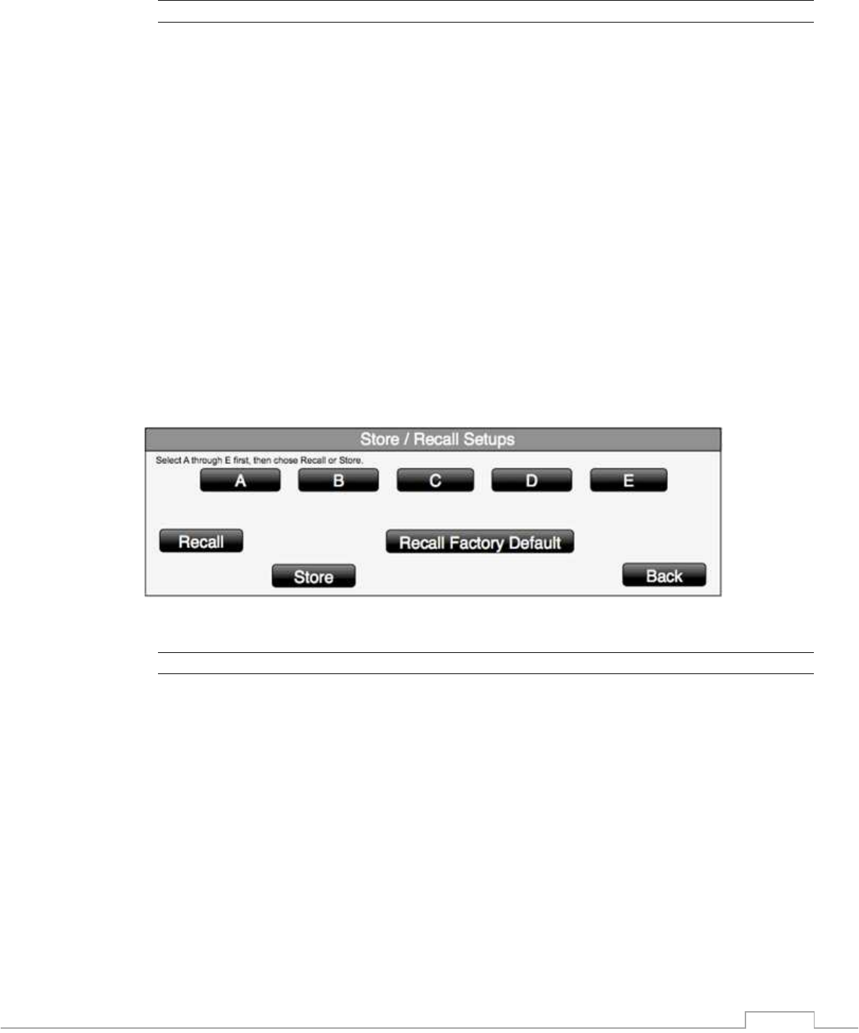
3. Select “Store / Recall Setups“
4. Select the desired position to store
• Note: the first user setting (A) is the default setting and will automatically load upon
system power on
5. Touch the “Store” button to save the settings to that position
6. Touch the Back button to close the menu
NOTE
• The system will not store alarm Limits or sounds to “OFF”
• The settings A, B, C, D and E are all set to Factory Defaults upon initial shipment from
IRadimed.
2.2.12.8. Service Setup
The service setup menu contains technical utilities to test the system’s performance. Please
contact your service representative or reference the 3880 service manual for details.
2.2.12.9. Auto Settings Memory
(The following settings are automatically stored as set and recalled at power up)
• Last communication channel
• Notch Filter
• Language
2-63
2.3. Initial Use
2.3.1. Wireless Communication
The 3880 system utilizes specialized wireless technology to establish communications between
the 3880 Monitor, PODs and optional 3885-B Base Station Unit and 3885-T Remote Tablet.
Ensure that the 3880, ECG ePOD, SpO2 oPOD and optional 3885-B Base Station and Remote
Tablet are set to the same wireless channel. Please review the wireless setup section 2.2.12.4
for further details.
! CAUTION
• The remote alarm and messaging capabilities are only effective when the 3885-T
Remote Tablet is wirelessly communicating with the intended (same Channel) 3880
Monitor via the 3885-B Base Station. All must be on the same channel.
2.3.2. Operating Modes
2.3.2.1. Normal Monitor Mode
The main running screen displayed without open menus, option lists or information boxes is
considered the Normal Monitor Mode.
2-64
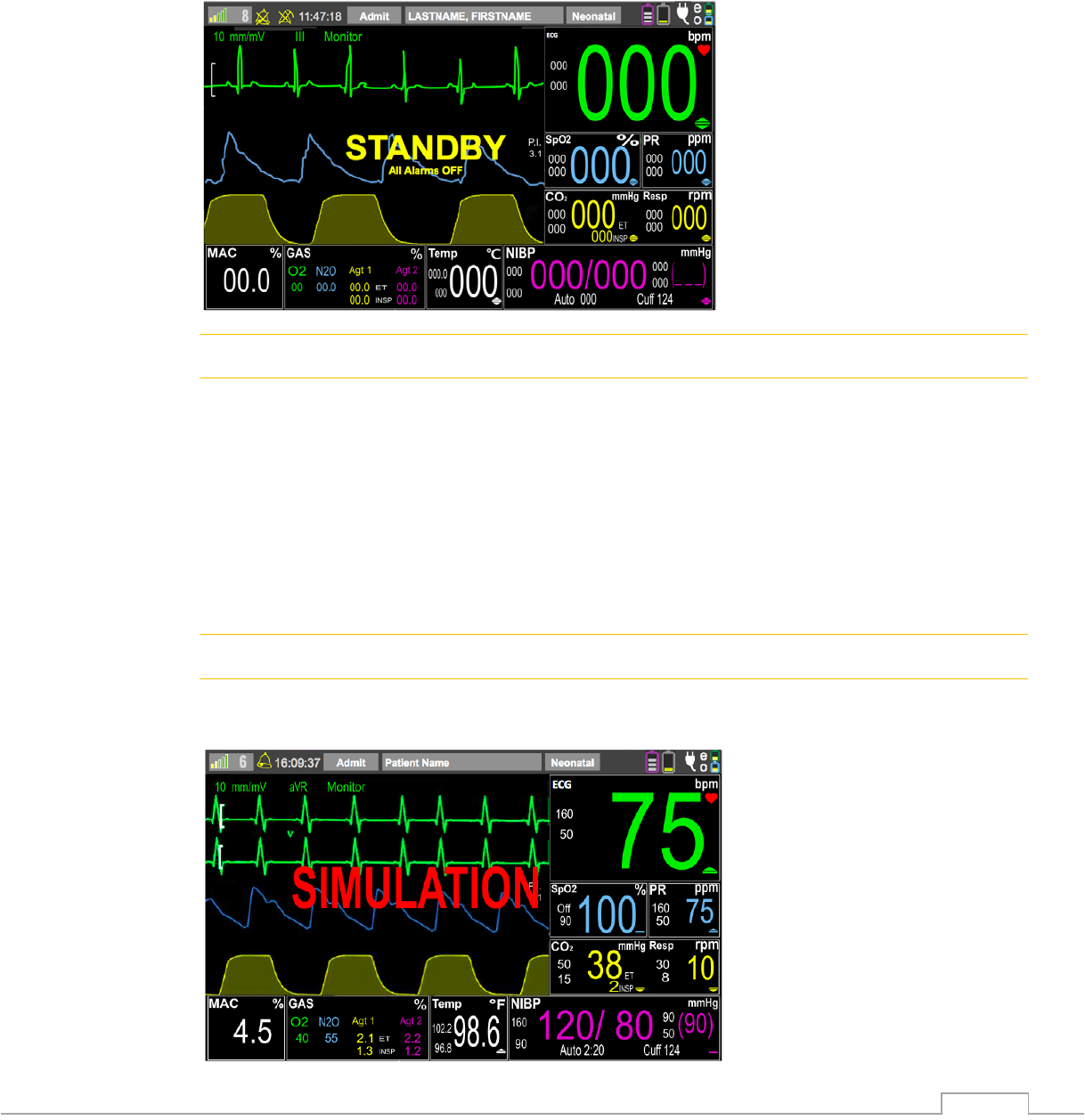
2.3.2.2. Standby Mode, ALARMS OFF
Pressing the ALARM OFF /STANDBY button places all communicated system components into
standby mode with all ALARMS OFF and silences all audible alarms, pauses Tri-Color Alarm
Dome Light, suspends automatic blood pressure cycles and suspends any automatic printout.
This feature is useful during patient setup and in between cases.
To exit Standby Mode press the ALARM OFF /STANDBY button again.
! WARNING
• ALARM OFF /STANDBY mode is intended to keep the monitor idle but active in
between patients and is not intended for active patient monitoring. Audible alarms and
the Tri-Color Alarm Dome Light are not enabled in STANDBY mode.
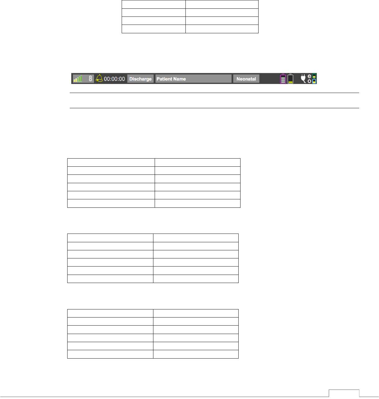
2.3.2.3. Simulation Mode, Only available from Service Mode
Simulation mode displays local or remote internally-generated vital sign waveforms, numeric
and statuses for training, testing and demonstration purposes. All patient monitoring functions
are suspended in simulation mode and “SIMULATION” will be flashing in red in the message
prompt area as well as displayed on any printouts.
! WARNING
• Do not attach a patient to the system when in Simulation Mode and do not activate the
mode when a patient is connected to the system. The system will not monitor patients
while in simulation mode.
2-65
2.3.3. Patient Type
This menu allows you to select the appropriate type of patient when monitoring, as several
parameters including NIBP cuff inflation pressure, pulse sensitivity and all alarm limits, defaults
and ranges, can vary depending on this selection.
ANSI/AAMI SP10:2008, the American National Standard for manual, electronic, or automated
sphygmomanometers, defines patient type according to the following age limitations:
Patient Type
Age
Neonatal
Birth to 28 days
Pediatric
29 days to 12 years
Adult
Greater than 12 years
To adjust the patient type, follow these steps:
1. Touch the patient type indicator at the top of the screen
2. Select the appropriate patient type from the drop down menu
! CAUTION
• There may be occasions when a particular selection is not suitable for its apparent
category of patients based on age alone. In these cases, a clinical decision shall be
made to use another patient type or measurement technique.
2.3.3.1. Adult Patient Type Operation Range
Heart Rate Range
30 – 250 bpm (ECG)
Respiration Rate Range
3 – 120 rpm
Systolic Range
40 – 270 mmHg
Diastolic Range
25 – 245 mmHg
Mean Range
30 – 255 mmHg
Cuff Inflation Pressure
270 mmHg, max
2.3.3.2. Pediatric Patient Type Range of Settings
Heart Rate Range
30 – 250 bpm (ECG)
Respiration Rate Range
3 – 120 rpm
Systolic Range
40 – 270 mmHg
Diastolic Range
25 – 245 mmHg
Mean Range
30 – 255 mmHg
Cuff Inflation Pressure
270 mmHg, max
2.3.3.3. Neonatal Patient Type Range of Settings
Heart Rate Range
30 – 250 bpm (ECG)
Respiration Rate Range
3 – 120 rpm
Systolic Range
30 – 130 mmHg
Diastolic Range
10 – 100 mmHg
Mean Range
15 – 120 mmHg
Cuff Inflation Pressure
140 mmHg, max

2-66
2.3.4. Filter Operation
Although it may appear that electrocardiogram (ECG) monitoring in the Magnetic Resonance
Imaging (MRI) area is similar to that performed in other areas of the clinical environment, the
conditions found inside the MRI area are unique and require additional precautions to be
followed in order to permit the safe monitoring of the patient during MRI procedures. Please
reference the ECG Monitoring section 6.1 for further ECG application details.
2.3.4.1. Monitor Mode
This filter mode provides ECG waveform filtering characteristics that meet the specification of
the Association for the Advancement of Medical Instrumentation (AAMI).
NOTE
• Note that this filter will not provide optimum performance during active MRI sequences.
2.3.4.2. MRI Mode
This filter mode provides special signal processing to reduce MRI gradient signals which
become superimposed upon the patient’s ECG. This MRI filter utilizes an adaptive slew rate
limiting scheme for reduction of gradient artifact generated by MR systems. The MRI Mode
filter also limits the ECG bandwidth to reduce the effects of magneto-hydrodynamic distortions
caused in the MR magnetic field and allow optimum HR counting. Resultant ECG waveforms
are not per AAMI standard nor AHA specification and may vary significantly from those
standards.
3-1
3. Advanced Case Management Strategies
The 3880 system includes several features to help facilitate the efficient management of
patients undergoing a MRI procedure.
3.1. Case Management
Many of the case management strategies are intended for use with a fully equipped 3880
system including the 3885-B Base Station and 3885-T Remote Tablet. Various strategy
suggestions provided in this document are examples showing the capabilities of the system.
Always consult local policy prior to initiating any strategy into clinical practice.
3.1.1. Preparing for a patient
Prior to starting the case certain monitor features can be prepared.
• Proper use of the ALARM OFF /STANDBY feature is an efficient way to suspend
alarms and NIBP patients in between patients
• Configure the monitor with the correct settings and patient worn accessories
appropriate for the case
• Edit the patient identifiers specific to the case
3.1.1.1. Clearing previous data
If trend data is still stored inside the monitor from a previous patient it can be erased by
following these steps.
1. Press the Trends hard key button
2. Select the “CLEAR” Trends soft key button
3. Select Yes to confirm
4. Touch the Back button to exit
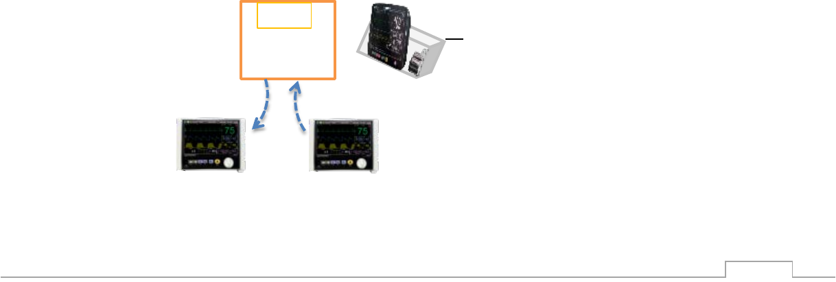
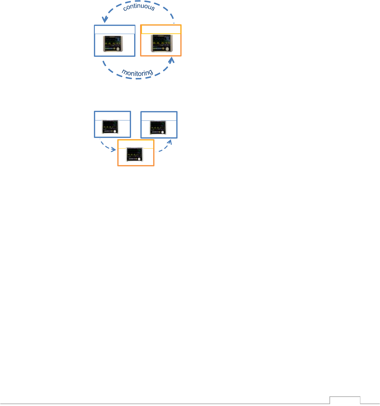
3.2. Multiple System Wireless Strategies
The 3880 system’s extended range wireless can help improve the efficiency for environments
that want to improve MRI throughput. MRI rooms that utilize multiple 3880 monitors with a
single Base station can gain efficiencies through monitor rotation. When owning multiple
systems ensure that each 3880 has a unique wireless channel. Additionally each installed
3885-B Base Station cannot share a wireless channel with another Base Station within range,
at the facility. Set the 3885-T Tablet and 3885-B Base to the same wireless channels to match
the 3880 monitor that the patient arrives on.
MRI
ROOM
Wireless
Channel
1
Wireless
Channel
2
Alternate base and Tablet
between Wireless Channel 1
and 2 depending on which
3880 is in the MRI room.
Verify Base and Tablet are on
the SAME channel
3-2
3.3. Patient Transportation
The small size and light weight nature of the 3880 patient monitor allows continuous patient
monitoring throughout the entire care cycle.
• Inpatient Workflow Example
• Anesthesia Workflow Example
MRI Room
Induction
Room
Continuous Monitoring
Recovery Room
MRI ROOM
ICU ROOM
4-1
4. Using Alarms and Messages
The 3880 MRI Patient Monitor features a comprehensive alarm system combining visual and
audible indicators. Alarms triggered by a vital sign or by a technical problem of the patient
monitor are indicated to the user by visual and audible alarm indications.
NOTE
• If any alarm recurs without apparent cause, verify the alarm limits are set appropriately.
Readjust the limit if necessary and ensure that the alarm limits chosen are clinically
appropriate for the patient being monitored.
4.1. Alarm Categories
! WARNING
• It is recommended that all 3880 systems be stored with the same settings to avoid any
confusion among users. A potential hazard can exist if different alarm presets are used
for the same or similar equipment in any single area.
4.1.1. Physiological Alarms
Physiological alarms, sometimes called patient status alarms, are triggered by a monitored
parameter value that violates alarm limits.
4.1.2. Technical Alarms
Technical alarms are triggered by improper operation or a device related issue. Technical alarm
messages are displayed in the Messages and Alerts area.
4.1.3. Messages
Apart from the physiological and technical alarm messages, the patient monitor will also show
some messages telling the system status such as CO2 zeroing. Messages of this kind are
displayed in the Messages and Alerts area. Messages associated with vital signs can be viewed
in section 6.
Messages
and Alerts
area

4-2
4.1.3.1. Message System Overview
The 3880 is equipped with a message area which automatically prioritizes and sorts messages
in order of priority. When a message is present, it will show up in the lower left hand corner of
the screen. Messages related to vital signs are color coded to priority and typically use a prefix
denoting the associated vital sign before the message so the operators can quickly understand
the context. The messages prefixes are as follows:
• ECG : Electrocardiogram and HR related messages
• SpO2: Pulse Oximetry related messages
• CO2: Capnography, Gas and respiration related messages
• Gas: Anesthetic agent related messages
• NIBP: Non-Invasive blood pressure related messages
• Temp: Temperature related messages
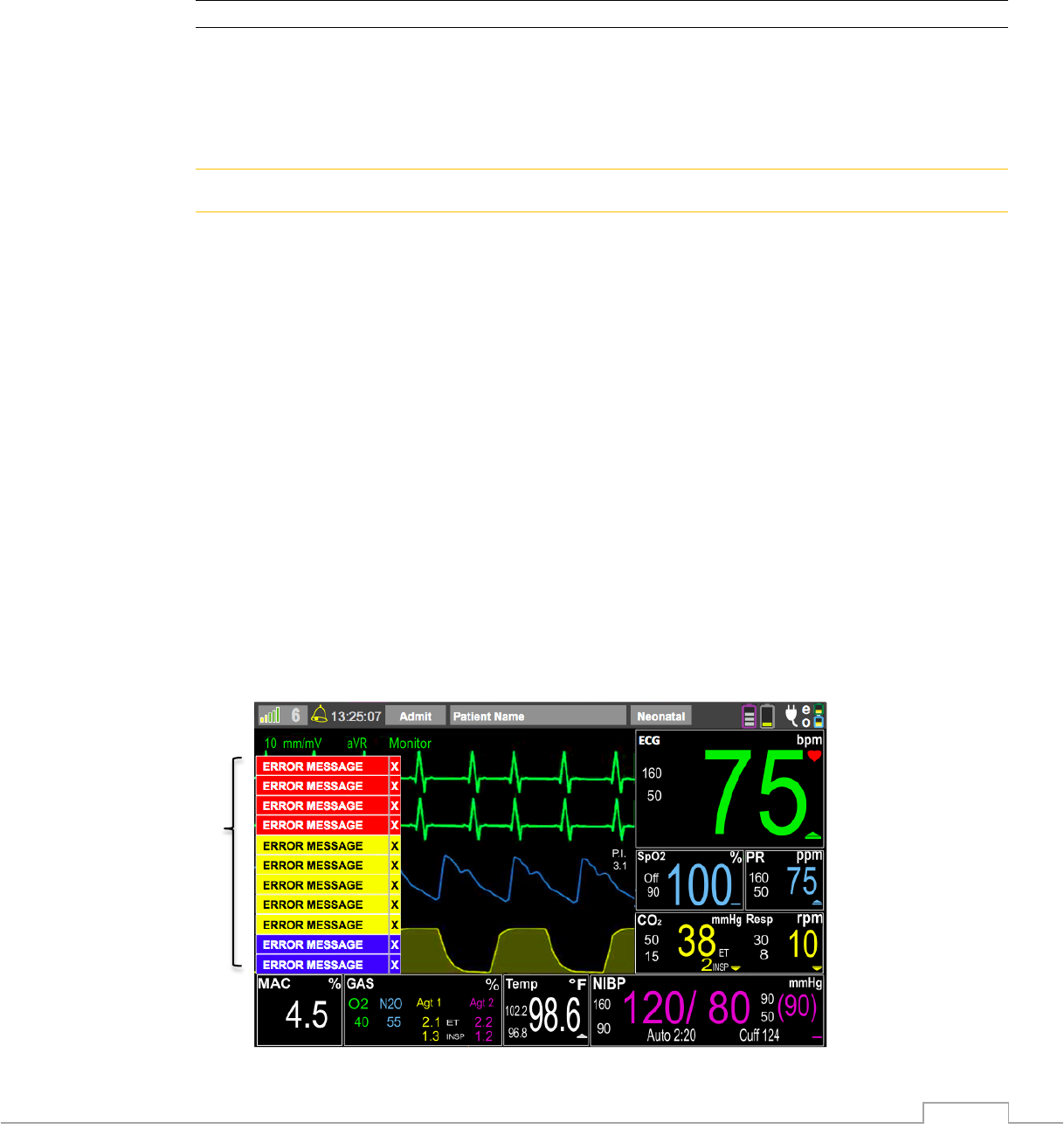
4.1.3.2. Multiple messages
If there is an unacknowledged message displayed in the bottom left side of the screen when a
subsequent message is generated the messages will stack vertically on top of each other. A
maximum of 10 messages can be displayed at a time. Messages are arranged by priority, with
higher priority messages on top as illustrated 4.1.3.
4.1.3.3. Message Priority
Messages are color coded to quickly alert the operator to the priority of the alarm. The colors
used for messages are as follows:
• Red - High Priority messages indicate a severe situation that needs immediate
response from the operator.
• Yellow – Medium Priority messages indicate a serious situation that requires prompt
operator attention.
• Blue – Low Priority messages indicate situations that the operator needs to be aware of.
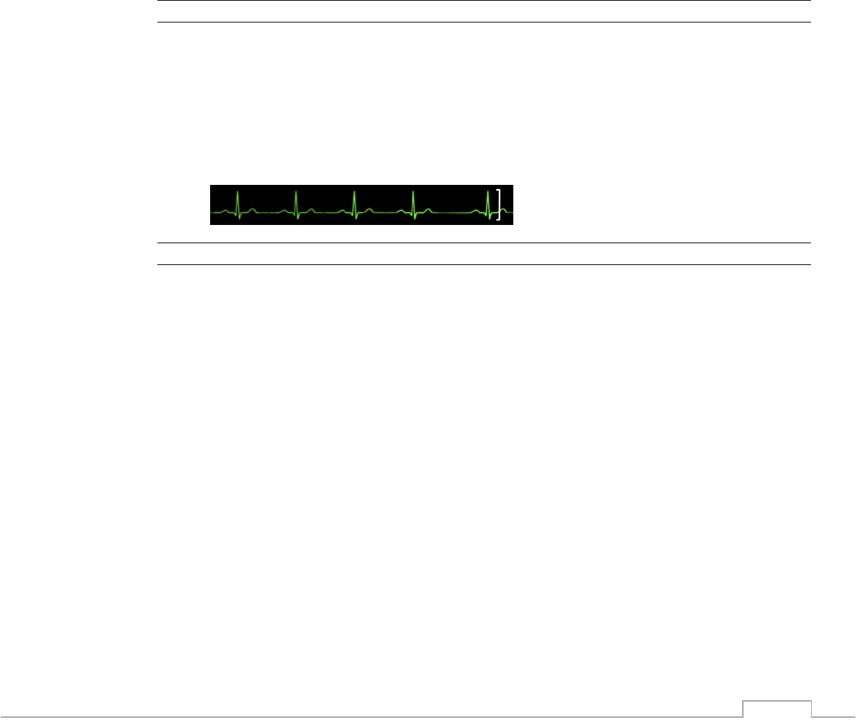
4.1.3.4. Acknowledgment and clearing of messages
Messages will automatically clear and be removed from the screen when the event that
generated the message is resolved. Users may also manually acknowledge the message and
remove messages from the screen even if event is still present. Users can manually
acknowledge and clear messages by touching the individual message from the message stack
that they want to clear. Each message will display a [X] at the end as shown below as a visual
indicator that user action is needed. By closing the message the user acknowledges the
message and it will only reappear if the triggering condition is met again.
4.1.3.5. Exceeding Message Display Limit
In the event there are multiple, simultaneous messages exceeding the displayable area of 10
stacked messages, a high priority flashing and sound will be triggered along with the high
priority message in the eleventh and top position flashing “SEE MESSAGES!” This 11th and top
position is reserved for only the “SEE MESSAGES” message. As users start to acknowledge
and clear the messages, any yet to be displayed message will be appear according to priority in
the newly created real-estate.
NIBP Time Out
X
SEE MESSAGES!
X

4-3
4.1.4. Alarm Levels
By severity, the patient monitor’s alarms can be classified into three categories: high priority,
medium priority and low priority.
NOTE
• All monitor alarms are categorized as medium priority, unless otherwise stated.
4.1.4.1. High Priority Alarms indicated by red Dome Light
Physiological Alarms
Technical Alarms
High Priority Alarm
Indicates Patient is in a life
threatening situation or a medium
priority alarm that has been
ignored and requires immediate
response.
Indicates a severe device
related issue which could
result in the system not
operating properly.
4.1.4.2. Medium Priority Alarms indicated by yellow Dome Light
Physiological Alarms
Technical Alarms
Medium Priority Alarm
Indicates serious but not life
threatening problems or a low
priority alarm that has been
ignored and requires prompt
operator attention.
Indicates a device related
issue or improper operation
that may compromise the
ability to monitor a patient
4.1.4.3. Low Priority Alarms indicated by blue Dome Light
Physiological Alarms
Technical Alarms
Low Priority Alarm
Indicates vital signs appear
abnormal and the operator needs
to be aware of this condition.
Indicates a device related
issue or operation which may
compromise certain monitor
functions but allow
monitoring to continue.
4.2. Visual Alarm Indications
When an alarm occurs, the patient monitor will indicate it to the user through visual and/or
audible alarm indications.
• Tri-Color Alarm Dome Light
• Alarm message
• Flashing numeric
• Flashing waveform
• Audible alarm tones
• Reminder tones

4-4
4.2.1. Alarm Identification
4.2.1.1. Audible Alarm Pattern
• HIGH Red: For life threatening situations:
o 10 repeated every 2.6 seconds
--- -- --- -- 2.6 --- -- --- -- 2.6 --- -- --- -- (rising tone)
• MED Yellow: For serious but not life threatening problems:
o 3 tones repeated every 3.6 seconds
--- 3.6 --- 3.6 –
• LOW Blue: For Low Priority Alarms
o Single tone, repeats after 14.4 seconds
! WARNING
• Always keep the patient under close surveillance and operate at a pretested volume
appropriate for the use environment.
• Do not rely exclusively on the audible alarm system for patient monitoring. Adjustment of
alarm volume to a low level may result in a hazard to the patient.
4.2.1.2. Tri-Color Alarm Dome Light Indicator
Red: HIGH PRIORITY ALARMS require an immediate response. (flashing red corresponding
with audible alarm)
Yellow: MEDIUM PRIORITY ALARMS require a prompt response. (flashing yellow
corresponding with audible alarm)
Blue: LOW PRIORITY ALARMS require you to be aware of this condition. (solid blue
corresponding with audible alarm)
4.2.1.3. Vital Sign Numerical Box Visual Indicator
If a physiological alarm is triggered by an alarm limit violation, the numeric value of the
measurement alarm will flash in a RED color once per second.
4.2.1.4. Vital Sign Waveform Visual Indicator
If a physiological alarm is triggered by an alarm limit violation, the waveform will continue to
display real time information.
4-5
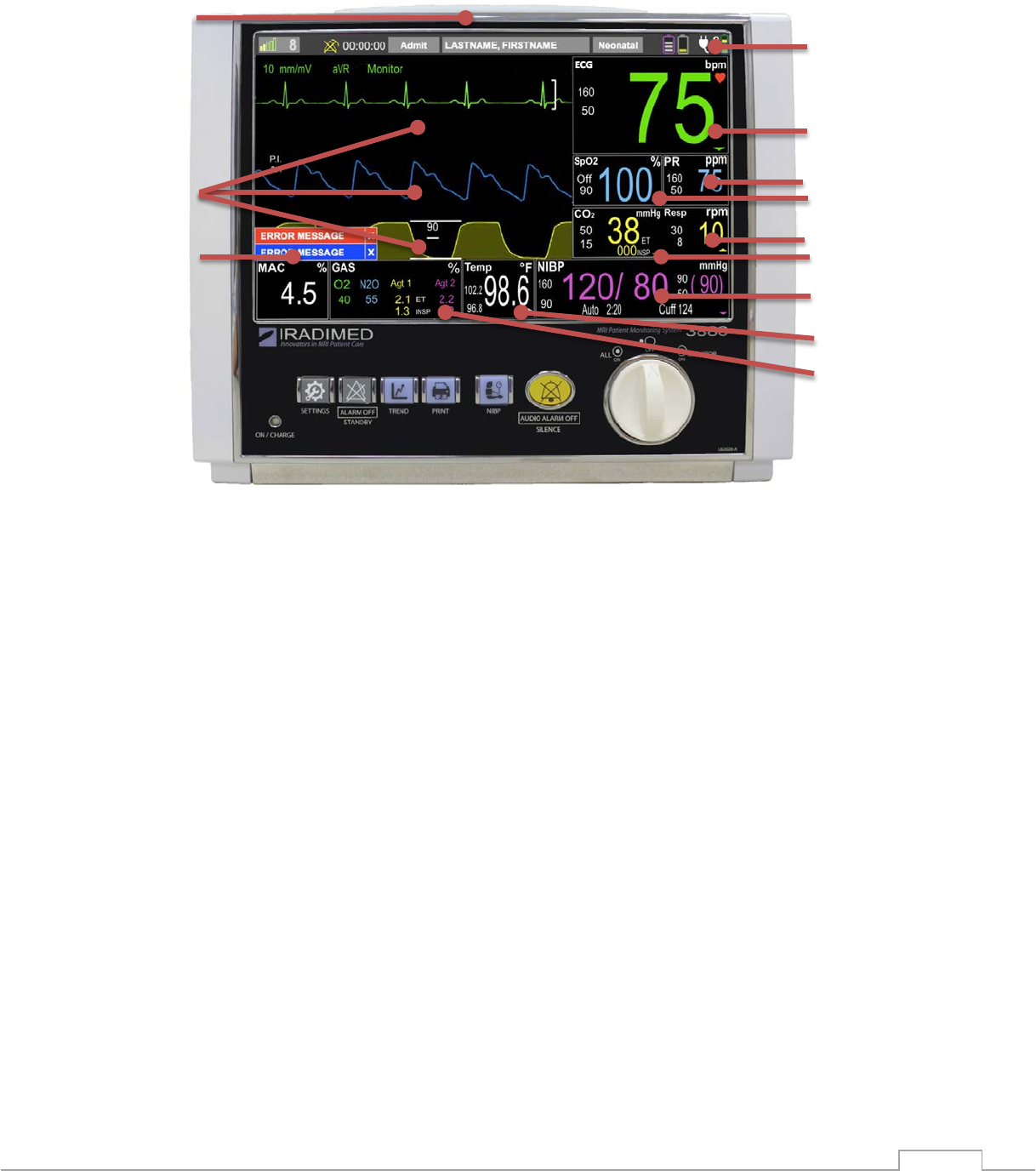
4.2.1.5. Monitor Visual Alarm Indicators
1. Tri-Color Alarm Dome Light Indicator
2. Vital Sign Waveforms
3. Messages and Alerts area
4. Battery and Communication Graphic
5. Vital Sign Numerical Boxes
5
2
1
4
5
5
5
5
5
5
5
3
4-6
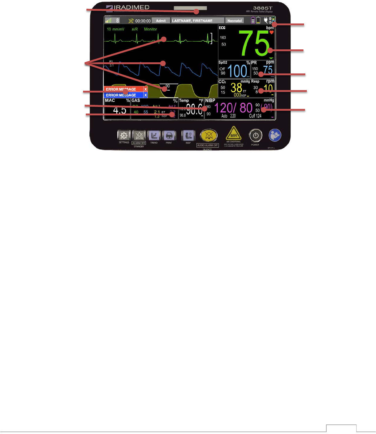
4.2.1.6. 3885-T Remote Tablet Visual Alarm Indicators
1. Tri-Color Alarm Dome Light Indicator
2. Vital Sign Waveforms
3. Messages and Alerts area
4. Battery and Communication Graphic
5. Vital Sign Numerical Box
4
1
5
2
3
5
5
5
5
5

4-7
4.3. Alarm Functionality
4.3.1. Alarm Condition Delay
Unless specified for a particular alarm condition visual and audible alarms at the 3880 monitor
will be triggered within 1 second of the initial alarm condition measurement.
The average additional delay time to indicate a 3880 Monitor alarm at the optional 3885-T
Remote Tablet is 1 additional second or less.
! CAUTION
• In situations where there is poor radio communication a COMM LOSS message will
display within 2 seconds and the Remote Tablet display Vital Signs numerics all display
“- - -“. During COMM LOSS, the 3885-T Remote Tablet may not reflect the current
status or alarms on the 3880 MRI patient monitor, however the 3880 Monitor unit will
maintain proper function with all alarm capability operational.
4.3.2. Alarm Latching
The factory default setting for all alarms is unlatched. When a user enables latched alarms the
alarm indication remains even after the alarm condition resolves. Latching of alarms occurs
only for vital signs limits violations. To acknowledge and silence the audible alarm, press the
Alarms Silence key once momentarily, however the tri-color dome light and vital signs numeric
value and associated waveform will continue visually indicating limits violation until the vital sign
returns to within limits.
4.3.3. Multiple Overlapping Alarms
When there are multiple simultaneous alarms, the monitor’s audible and Tri-Color Dome Alarm
Light Indicators will adopt the highest priority alarm that is currently present. Any vital sign
numerical value or waveform that is in an alarm condition will flash simultaneously.
! WARNING
• When the Alarm Silence button is pressed during multiple alarm conditions it will silence
all alarms, whether limit violations or alert/messages.
The Alarm Priority hierarchy ranked from most important to least is as follows:
1. Physiological Vital Sign High Priority
2. Technical High Priority
3. Physiological Vital Sign Medium Priority
4. Technical Medium Priority
5. Physiological Low Vital Sign Priority
6. Technical Low Priority
4-8
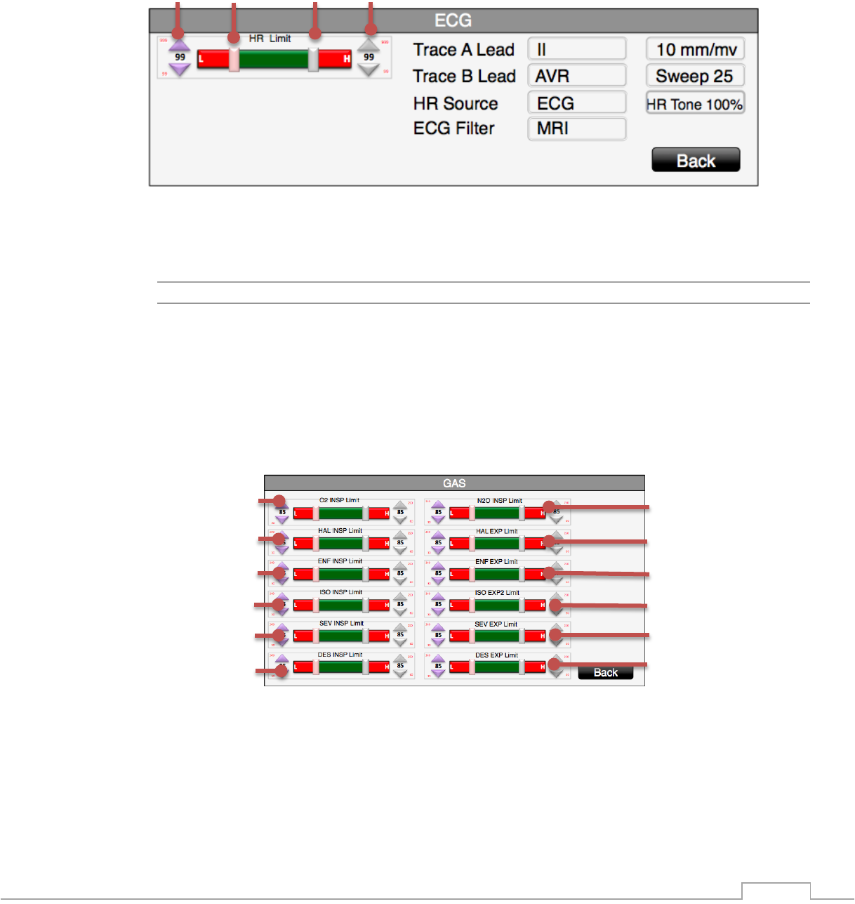
4.4. Controlling Alarms
4.4.1. Accessing Alarm Menu
Quick Alarm setup allows a targeted adjustment of 1 vital sign measurement. The “quick alarm”
is accessed by a user by pressing the corresponding vital sign box.
1. Lower Alarm Limit Fine Adjustment
2. Lower Alarm Limit Quick Slide Adjustment
3. Upper Alarm Limit Quick Slide Adjustment
4. Upper Alarm Limit Fine Adjustment
NOTE
• Green: range of numerical values that are inside the alarm limits and will not trigger an
alarm.
• Red: range of numerical values that are outside the alarm limits and will trigger an
alarm.
• The system automatically prevents the crossover of High and Low Limit settings.
4.4.2 Gas (Anesthetic Agent) Alarm Screen
1. Nitrous Oxide (N2O) Inspired Limit Selector, high limit cannot be set above 80%
2. Halothane (Hal) Expired Limit Selector
3. Enflurane (Enf) Expired Limit Selector
4. Isoflurane (Iso) Expired Limit Selector
5. Sevoflurane (Sev) Expired Limit Selector
6. Desflurane (Des) Expired Limit Selector
7. Oxygen (O2) Inspired Limit Selector, cannot be set below 18% without special key
8. Halothane (Hal) Inspired Limit Selector
8
7
4
5
6
3
2
1
12
11
10
9
4
3
2
1

4-9
9. Enflurane (Enf) Inspired Limit Selector
10. Isoflurane (Iso) Inspired Limit Selector
11. Sevoflurane (Sev) Inspired Limit Selector
12. Desflurane (Des) Inspired Limit Selector
NOTE
• Green: range of numerical values that are inside the alarm limits and will not trigger an
alarm.
• Red: range of numerical values that are outside the alarm limits and will trigger an
alarm.
• O2 Low Limit settings below 18% require an unlock sequence second touch at the
center of the Lower Limit Up/Down arrows.
• N2O High Limit cannot be adjusted above 80%.
4.4.3. Enabling and Disabling Alarms
4.4.3.1. Adjust Alarms
All physiological alarm upper and lower limits can be set to “OFF” which will prevent the visual
and audible indicators from alarming. Always select clinically appropriate alarm limits for the
patient being monitored.
To adjust the alarms follow these steps:
1. Access the Quick Alarm screen by following steps detailed in section 4.4.1.
2. For fine adjustments touch the arrow associated with the direction you want the alarm
limit value to change
a. The downward facing arrow will decrease the numerical value
b. The upward facing arrow will increase the numerical value
3. For normal adjustments firmly touch and hold the Quick Slider and slowly move your
finger in the direction you want the alarm limit value to change.
! WARNING
• Pausing or switching off alarms may result in a hazard to the patient.
• Make sure that the alarm limit settings are appropriate for your patient before
monitoring.
• Setting alarm limits to inappropriate values for your patient may cause the alarm system
to become ineffective.
4.4.4. Alarm Silence Button, Alarm Audio Off
4.4.4.1. Silencing Alarms
During an Alarm Condition, the operator can press the ALARM SILENCE button to silence the
audible alarm that triggered the event and stop the Tri-Color Alarm Dome Light from flashing.
Once a new alarm condition arises, the audible alarms and Tri-Color Alarm Dome Light will be
reactivated. The alarm Tri Color Dome and numerics visual signaling will continue as long as
the alarm condition persists.
4-10
4.4.4.2. Pausing Alarms Temporarily
If the operator presses and holds the Alarm Silence button for 2 seconds the system will
“Pause” all audible alarm sound operation for 2 minutes.
NOTE
• Pressing the Alarm Silence button stops the alarm sound and dome light indicators, the
visual waveform and numerical alarms are not affected.
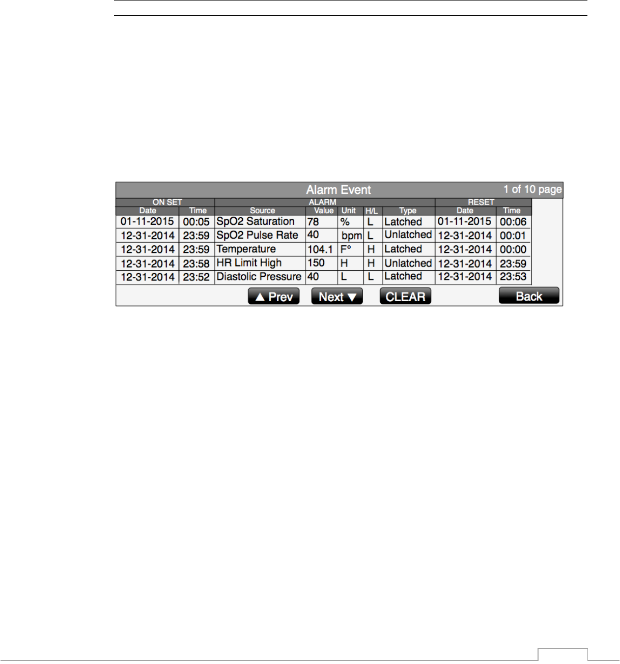
4.4.5 Alarm Event Log
A tabular log of all vital signs alarm events is maintained during all operating times.
Should a vital sign limit be exceeded (high or low) an entry of the event is created with
on-set time/date, source of the alarm, its value at on-set, indication L or H for Low or
High limit violation, type; Latched or unlatched, and time/date the alarm resets.
In addition to the vital signs limit violation alarms, several technical alarms/alerts are also
logged. Technical alarms recorded are: POST Fail, NIBP Tim e Out , NIBP Over Press, Data
Delay, Lead Fail, Probe Off, SEE M ESSAGES! The activation/deactivation of alarms
Suspend/ALARMS OFF is also logged.
Fift y events are recorded, as first in/first out. These events are continuously added and
only cleared via manually pressing “CLEAR”.
5-1
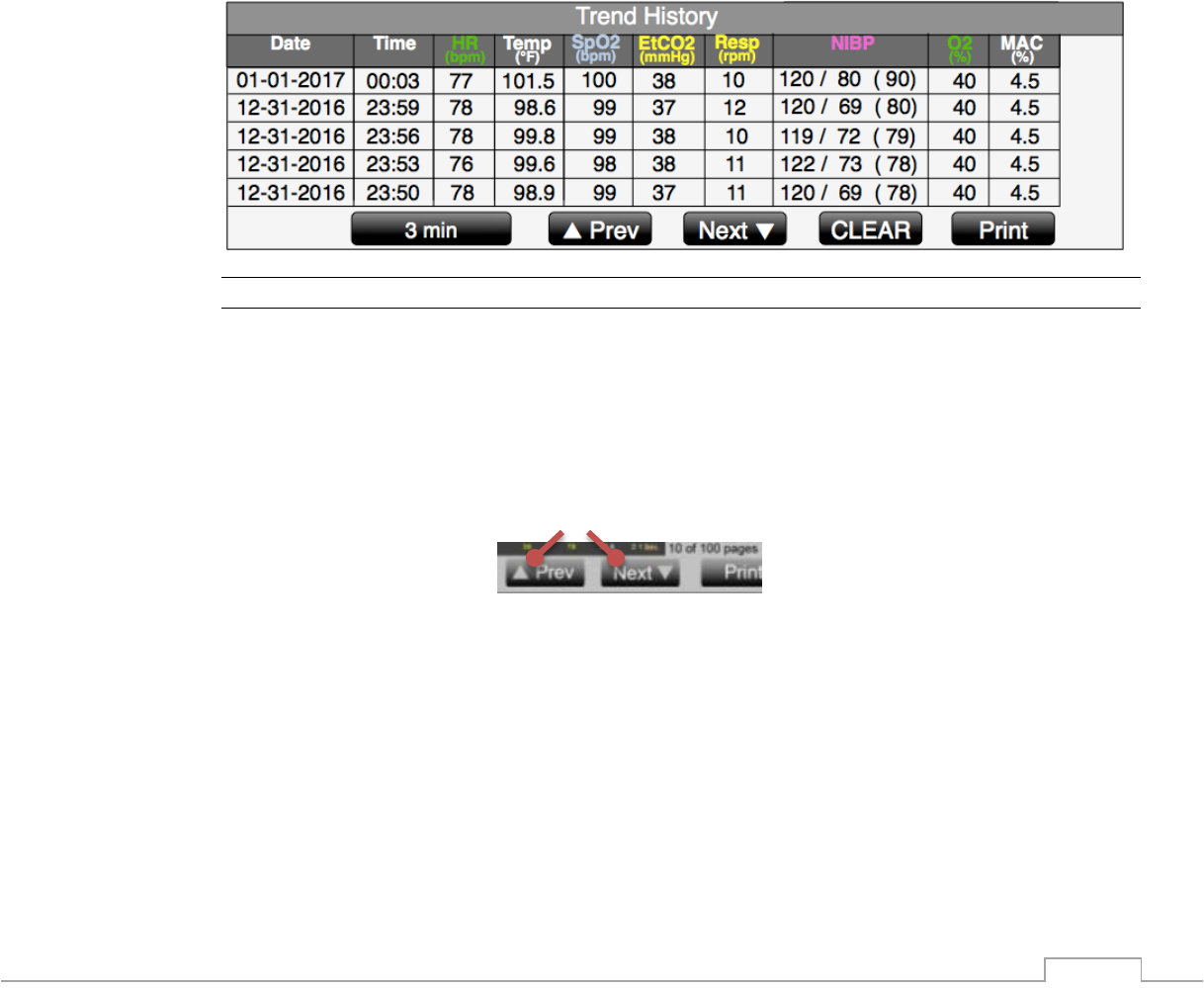
5. Using Trends
5.1. Overview
The 3880 MRI patient monitoring system enables you to view trend data. The monitor collects
numerical trend data automatically from trended variables. Patient trend data is stored for up to
24 hours and is color coded to match the monitored vital signs. Once the data is stored, new
data will overwrite the oldest trend data.
Trended Parameters:
• Heart Rate
• Non Invasive Blood Pressures
• Pulse Oxygen Saturation
• Respiration Rate
• EtCO2
• Temperature
• O2
• MAC
NOTE
• Trends will automatically be erased when a patient is Discharged.
5.2. Page Navigation
To view the patient trend information press the TRENDS button. When patient data exceeds
what can be seen on the screen it will store the data on additional pages. To view data on
another page press navigational arrows .

5-2
5.3. Trend Interval
The 3880 system can store trend information at the following intervals:
• OFF
• 3 minute ( This is the Factory Default Setting)
• 5 minutes
• 8 minutes
• 10 minutes
• 15 minutes
• 30 minutes
• NIBP Auto Time
NOTE
• NIBP Auto Time will automatically store vital sign information when a new NIBP
pressure is recorded.
To adjust the trend interval follow these steps:
1. Press the TRENDS button
2. Select “Trend Interval”
3. Make your selection
4. Touch the Back button to close the menu
5.4. Clearing Trends
Clearing trends removes all patient history from the 3880 monitor and optional 3885-T Remote
Tablet. Clearing the trends is useful to ensure that the monitored information reflects data for
only one patient. To prevent accidental clearing of the patient data, a YES/NO confirmation
menu choice is provided before data is cleared. The operator must confirm data clearing by
selecting the YES choice. A delay of approximately 30 seconds without any selection is
equivalent to selecting NO. At the end of this period, the confirmation menu choice is removed
without clearing the patient data.
Trends will clear automatically when a patient is discharged.
To clear trends manually follow these steps:
1. Press TRENDS button
2. Select “CLEAR“
3. Confirm Selection
4. Touch the Back button to close the menu
Alternatively:
1. Press DISCHARGE button from information bar
2. Accept the confirmation
5.5. Print Page
Patient Trends may be printed through the optional 3885-B Base Station recorder. To print a
trend screen follow these steps:
1. Press TRENDS button
2. Touch “Print” button
3. Touch Back button to close the menu

6-1
6. Using Vital Sign Parameters
6.1. Cardiac Monitoring
6.1.1. ECG Overview
The electrocardiography, ECG, reflects the electrical activity generated by the heart muscle and
displays it on the patient monitor as a waveform and numeric heart rate value. ECG monitoring
in the MRI is used for a heart rate measurement and is not intended to diagnose arrhythmic
cardiac conditions. The 3880 MRI Patient Monitor uses a sophisticated heart rate averaging
algorithm which uses a multi-point median filter displaying the average of the middle three
points. The conditions found inside the MRI area are unique and require additional precautions
to be followed in order to permit the safe ECG monitoring of the patient during MRI procedures.
Monitoring ECG in the MRI environment is challenging because of the inherent distortion of the
ECG waveform caused by the MRI magnetic field that adds to the ECG T-wave amplitude.
Additional artifacts caused by the static, gradient, and RF electromagnetic fields can also
severely distort the ECG waveform. Since distortions may be associated with true physiologic
disorders a baseline recording of the ECG prior to placing the patient inside the MRI system
room will be necessary. The proper placement of the ECG electrodes in the MRI is critical to
reducing the distortion of the ECG waveform. Monitoring a different ECG lead (I, II, III, AVL,
AVR, AVF, V) can minimize some of these artifacts.
High radio frequency (RF) power used in MRI scanning poses a risk of excessive heat at the
monitoring sites and the risk of patient burn greatly increases with increased power levels are
used. As a result, monitoring of ECG at power levels of greater than a MRI system reported,
whole body averaged SAR of 4 W/kg is not recommended for the general patient population.
Such monitoring must only be attempted on conscious patients with normal thermoregulatory
capabilities so they may warn the operator of possible excessive heat at the monitoring sites.
The ECG patient lead wires are short and constructed of special lossy material to reduce the
amount of radio frequency (RF) energy that can flow through these wires to mitigate risk RF
heating hazard. The lead wires nor the POD should not touch the MR system bore. Contact with
the MR system bore may cause heating of the POD or lead wires or patient electrode site. Use
of lead wires other than the IRadimed lead wires may cause excessive RF current to flow
through the wires, thus causing the potential for patient heating or burn. Use only the leads
described in section 9.3.
! WARNING
• Use only MRI lead wires and electrodes described in section 9.3
• Do not used damaged ECG lead wires, electrodes or ePODs
• Do not use electrodes with expired dates
• Do not immerse the ePOD or Lead wires completely in water solvents, or cleaning
solutions.
• Arrhythmias, erratic heart beats, operation of electrical stimulators, pacemakers and
patient motion can result in inaccurate readings. Rate meters may continue to count
pacemaker rates during occurrence of cardiac arrest or some arrhythmias. Do not rely
entirely upon rate meter alarms. If questionable readings are obtained, confirm patient’s
vital signs by alternate means before administering medication.
• The lead wires nor the POD should not touch the MR system bore. Contact with the MR
system bore may cause heating of the POD or lead wires or patient electrode site.
• When connecting electrodes and/or patient wires, make sure that the connectors never
come into contact with other conductive parts. In particular, make sure that all of the
ECG electrodes are attached to the patient, to prevent them from contacting conductive
parts or earth.

6-2
• Periodically inspect the electrode application site to ensure skin quality. If the skin
quality changes, replace the electrodes or change the application site.
• No pacemaker rejection is present, and to keep pacemaker patients, and patients with
arrhythmias, under close surveillance. Recommend using the SpO2 function as the
primary heart rate source under those conditions.
! CAUTION
• Pacer pulses are not specifically rejected and may be treated as part of the MRI gradient
noise. Gradient filtering attempts to remove high frequency pulse shaped waveforms
from the ECG signal which may resemble pacer waveforms, and it is possible that the
pacer waveform may be removed with the gradient noise.
• Placing the Wireless ECG ePOD within the field of view during the MRI procedure may
cause artifact on the MRI image.
• Use with a higher SAR greatly increases the risk of patient burns. If scanned directly
across the plane of the ECG electrode element, a slight image distortion may be seen at
the skin surface where the ECG electrode element is positioned.
• High levels of RF energy may cause patient heating or burns. Use caution for scans
greater than 15 minutes and above SAR of 2 W/Kg.
• Discontinue use if skin irritation or inflammation is noticed around the electrode site.
6.1.1.1. 3881 ECG ePOD
The 3881 ECG ePOD is designed for use in the MRI magnet and wirelessly communicates with
the 3880 patient monitoring unit.
6.1.1.2. 1812 ECG Lead wires
The 1812 ECG lead wires are designed for use in the MRI environment with the 3880 MRI
Patient monitoring system.
6.1.1.3. ECG Electrode
Use an electrode designed for use with MRI systems to minimize the risk of heating during MRI
procedures and reduce the amount of MRI generated artifact on the ECG waveform. The
Electrode can be used as a single patch or multiple electrode patch to provide optimal
performance across a diverse patient populations.
6.1.1.4. Setup Limitations
The following factors may affect the accuracy of measurement:
• Heart rate extremes of less than 40 bpm or greater than 300 bpm
• Electrode placement
• MRI gradients
• Patient skin preparation
• ECG filter
• ECG lead view selected
• Pacemaker presence
• QRS signal strength
• Type of MRI system, scan and/or body area being scanned
6-3
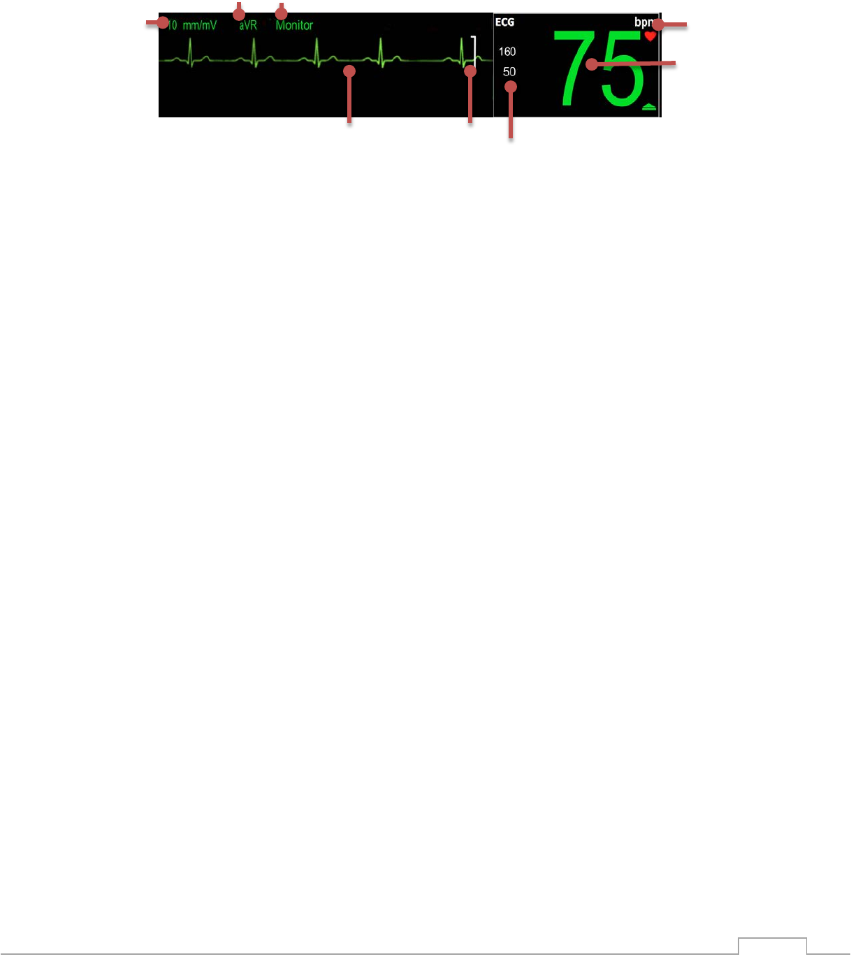
6.1.2. Understanding the Display
1. Measurement Unit
2. Current Heart Rate
3. Heart Rate Alarm Limits
4. ECG Waveform
5. ECG 1mv Scale Indicator
6. ECG Scale
7. ECG Lead View
8. ECG Filter
6-4
6.1.3. ECG Patient Application
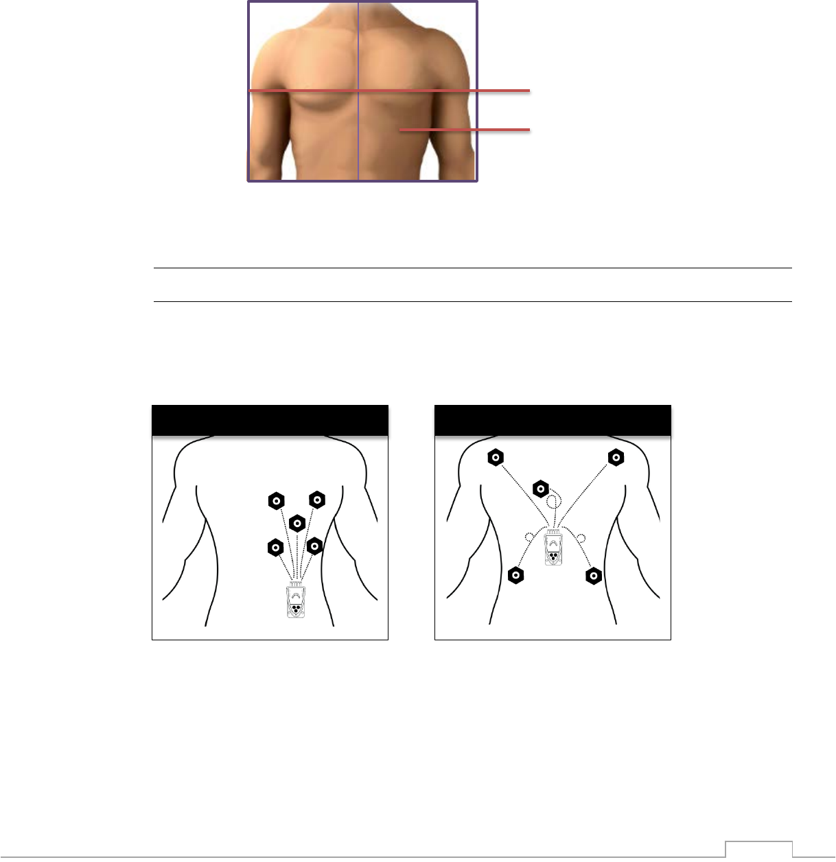
6.1.3.1. ECG Electrode Site Selection
A general guideline for non-neonatal applications, when placing the electrodes the RA and LA
electrodes should be placed just above the imaginary nipple line avoiding fatty breast tissue.
The RA and RL electrodes should be placed just to the left side of the sternum. The bottom
electrodes LA, LL should be placed along the bottom of the rib cage with the optional V lead
placed for the vector desired.
The purpose of such electrode placement is to minimize the loop area of the lead wires thereby
reducing gradient artifact, magneto hydro-dynamic artifact and possible RF energy pickup.
However the resultant ECG waveform with such placement becomes non-standard, though the
lead selector utilizes conventional standard lead designations of I, II, III, AVR, AVL, AVF, V.
! WARNING
The lead placement recommended in 6.1.3.1 above is non-standard though the lead selector
naming designations refer to the standard names of I, II, III, AVR, AVL, AVF, and V. The
placement in 6.1.3.1 is a reduced area of Eindhoven’s triangle and produces a non-standard
(per AHA) electrical view of heart activity which may vary significantly from the AHA standard.
Leads wires laid in straight and shortest path Leads spread wider than needed and not straight
L R
Imaginary Nipple Line
Rib Cage Bottom
Good Placement
Bad Placement
6-5
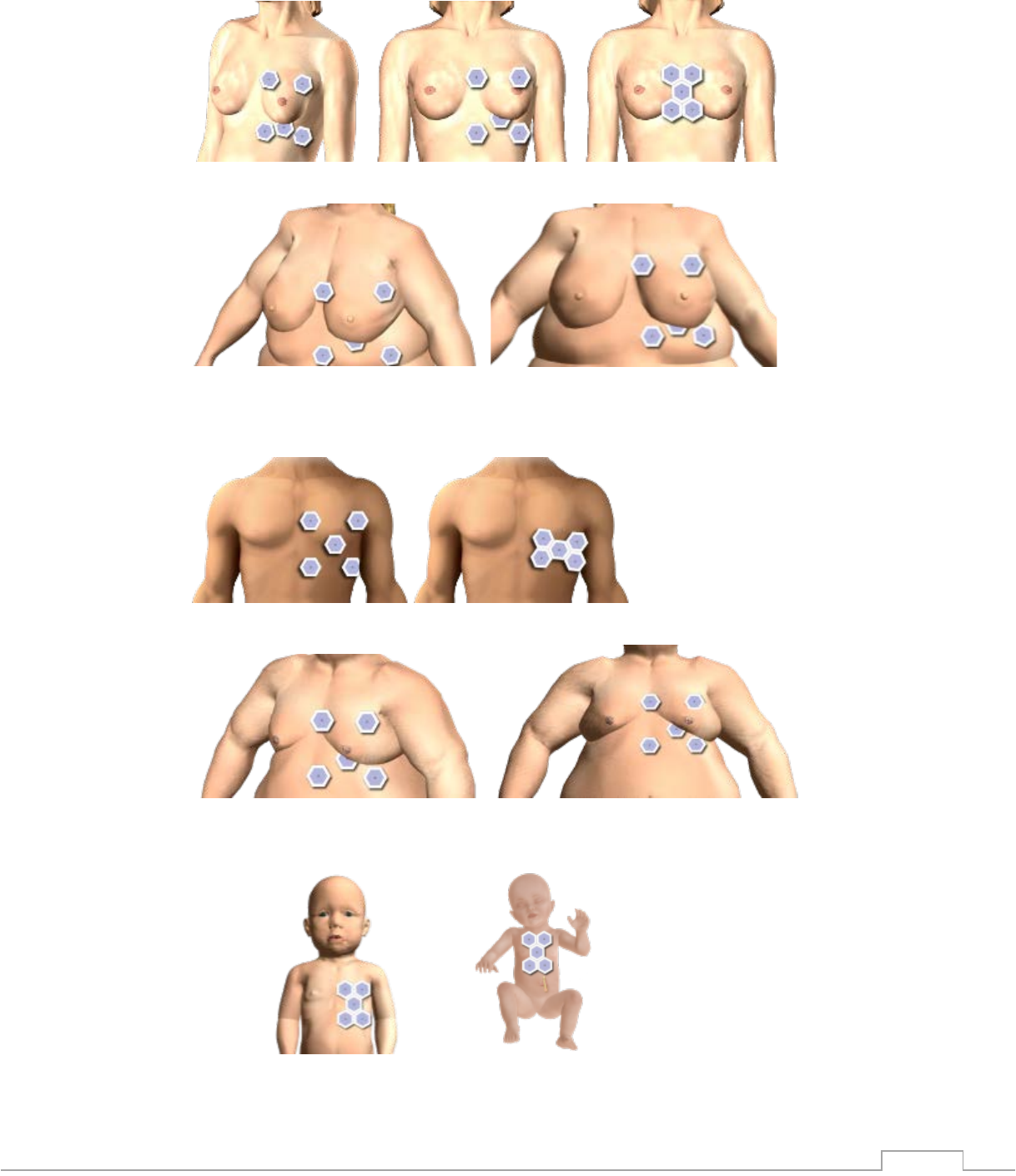
6.1.3.1.1. Female
Average Female Example
Obese Female Example
6.1.3.1.2. Male
Average Male Example
Obese Male Example
6.1.3.1.3. Pediatrics
6-6
6.1.3.2. Applying the ECG Electrode
ECG safety and quality during MRI procedures can be greatly affected by the quality of patient
preparation. To prepare the electrode site, follow these steps:
A. Preparing the Electrode Site
1. Select the electrode sites
2. Check the electrode expiration date
3. Shave any hair from the application site
B. Placing the Electrode on the Patient
4. Apply a sufficient amount of 1813 Skin Prep Gel to a gauze pad or cloth
5. Using a circular motion, rub the selected electrode sites with the Skin Prep Gel (skin
may turn pink)
6. Remove any Skin Prep Gel from the skin so the electrode will adhere
7. Apply an authorized and approved electrode to the patient
8. Connect the lead wires to the electrode
NOTE
• Do not place the ECG Electrode on top of breast tissue
• ECG Electrodes can be placed underneath breast tissue
• If the T wave is elevated larger than expected inside the MRI magnet, try applying a new
RA and LA electrodes in a lower position
C. Checking ECG Quality
9. Observe the displayed ECG waveform on the monitor. Check amplitude of the QRS
complex , to adjust touch the scale setting either directly indicating on the display (just
below the channel indicator in the upper left of the display) or in the ECG menu.
NOTE
• The ECG Scale changes how the ECG waveform is sized and has no effect on ECG
quality.
D. Make any needed adjustments
10. If the QRS complex is less than optimum try viewing another lead configuration.
Example, try LEAD I instead of LEAD II
11. If the QRS complex amplitude is less than 1/3 of the ECG Scale Indicator on all lead
choices remove the electrodes and prep the site again.
E. ECG Wire and POD Placement
12. Keep the ECG ePOD outside of the Field of View
13. Keep the lead wire straight and avoid “U”, “C” or “S” shapes
F. ECG Filter Selection
14. Select the appropriate filter for the ECG application
a. The 3880 is equipped with “Monitor” and “MRI” filters. Select “ MRI” when the
patient is inside the MRI bore.
6.1.3.3. Setup Checklist
• Electrode/gel is within expiration date and moist
• Electrodes have good skin contact
• Electrodes are positioned correctly

6-7
• ECG QRS signal is greater than1/3 of the Scale Indicator
• ECG Lead wire is positioned straight
• ECG ePOD is positioned outside of the field of view
• Ensure the ECG filter is appropriate for the MRI Scan
• Ensure SAR does not exceed 4 W/Kg
• ECG is selected to be displayed through Monitor Setup patient parameters menu
6.1.4. Changing ECG Settings
6.1.4.1. Trace A lead View
The ECG trace A is considered the primary ECG waveform and is the top position waveform
when both A and B waveform are enabled. The ECG trace A can display the following leads I,
II, III, V, AVL, AVF, AVR and CAL.
To adjust which lead is viewed on Waveform A follow these steps:
1. Touch the ECG vital sign box
2. Touch “Trace A” Lead
3. Select the desired lead (I, II, III, AVL, AVR, AVF, V, CAL)
4. Alternatively touch the ECG Filter description on above the ECG waveform
5. Touch Back Button to close the menu
NOTE
• The ECG derived heart rate is always calculated from Trace A even when a Trace B is
also displayed.
• CAL is not for clinical use
6.1.4.1.1. Trace B Lead View
The ECG Trace B is considered the secondary ECG waveform and is the lower ECG waveform
trace on the screen when enabled. The Trace B can display an additional waveform not
displayed in Waveform A.
To enable and or adjust which lead is viewed on Waveform B follow these steps:
1. Touch the ECG vital sign box
2. Touch “Trace B” Lead
3. Select the desired lead (OFF, I, II, III, AVL, AVR, AVF, V, CAL)
4. Touch Back Button to close the menu
6.1.4.2. Scale
The scale feature enables you to adjust the amplitude of an ECG waveform displayed.
To adjust the ECG scale, follow these steps:
1. Touch the ECG vital sign box
2. Touch Scale
3. Make Selection (5, 10, 15, 20, 25, 30 or 40 mm/mv)
(selection range is limited to 5, 10, 15 and 20 mm/mv with both trace A and B ON)
4. Touch Back button to close the menu
NOTE
• The ECG scale changes how the ECG waveform is displayed and has no effect on ECG
quality.
• Best results in MRI will be with the 5, 10, or 15 mm/mV scale
6-8
• See the WARNING at 6.1.3 regarding the non-standard lead placement and the
foreseeable changes the ECG waveform due to placement.
6.1.4.3. HR Source
HR Source permits the user to select the vital sign source that will to be used to produce the
heart rate displayed in the ECG vital sign box. The following options are available:
Option
Corresponding Vital Sign
ECG
Electrocardiogram
SpO2
Pulse Oximetry
NIBP
Most recent NIBP Measurement
6.1.4.4. Gating Source
The HR Source will not affect the gating signal that the 3880 monitor outputs.
• ECG – The gating pulse will be produced using data from the ECG vital sign, lead Trace
A only.
• SpO2 – No gating pulse will be produced using data from the SpO2 vital sign.
• NIBP – No gating pulse will be output from the 3880
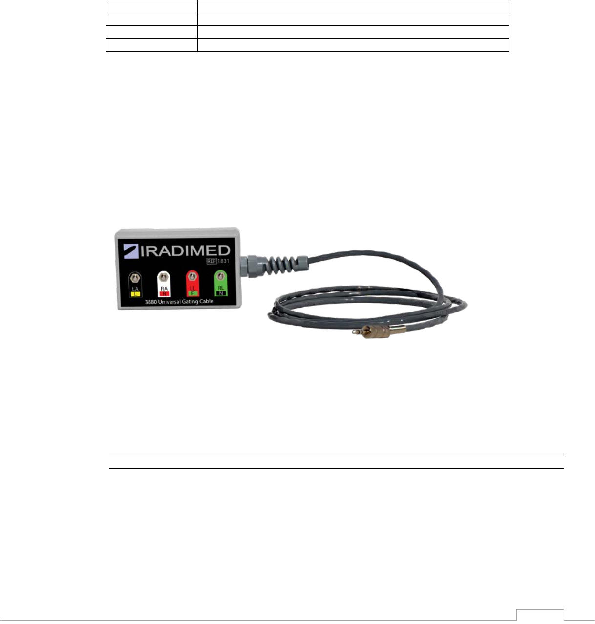
6.1.4.5. Gating Cable
The gating cable is a physical interface between the MRI scanner and the 3880 monitor. To
interface with the scanner follow these steps:
1. Connect the gating cable to the 3880 gating port
2. Locate the ECG gating cable that came with the scanner and instead of connecting it to
the patient electrodes connect it to the IRadimed 3880 gating cable. Match the
corresponding lead colors of the scanner gate cable to those of the IRadimed gating
connections.
NOTE
• The scanners ECG gating cable will always be used with this cable.

6-9
6.1.4.6. Sweep Rate
The sweep rate setting determines the speed at with the ECG waveform trace moves across
the display. You can change the waveform sweep rate between 25 mm/s and 50 mm/s by
selecting the appropriate setting under the ECG menu.
To adjust the sweep rate follow these steps:
1. Touch the ECG vital sign box
2. Touch Sweep button
3. Select 25 mm/s or 50 mm/s
4. Touch Back button to close the menu
6.1.5. HR Alarm Limit Menu (Heart Rate form QRS detection of Trace A)
Low Limit
Range
Default
Low
Default
High
High Limit
Range
Adult Heart Rate
Off, 30-239
50
120
50-250, Off
Pediatric Heart Rate
Off, 30-239
75
180
50-250, Off
Neonatal Heart Rate
Off, 30-239
90
200
50-250, Off
6.1.6. ECG Messages
Message
Trigger Condition
ECG Inop
Hardware or software failure detected
ECG Lead Fail
Lead wire is not connected to patient
Low ECG Battery
≤ 15% of battery capacity remaining in the ePOD
Change Channel
Multiple ePODs detected on the same wireless channel
6.2. Pulse Oximetry Monitoring
Pulse oximetry is used to continuously and noninvasively measure functional oxygen saturation
in the blood. Pulse oximetry is measured by using changes in light absorption, as the light
passes over a pulsating arteriolar bed. Pulse oximetry is also used to continuously and
noninvasively measure pulse rate, using a SpO2 sensor.
The pulse oximetry sensor contains two light-emitting diodes (LEDs). These LEDs emit specific
wavelengths of red and infrared light, which are measured by a photo detector. The oPOD
(SpO2) utilizes the Masimo SET technology for determining the pulse and SpO2, which is
transmitted to the 3880 Monitor for display of pulse rate and functional oxygen saturation as
percent SpO2. See the appendix for The Masimo SET Technology.
! WARNING
• If any measurement seems questionable, first check the patient’s vital signs by alternate
means and then check the pulse oximeter, oPOD for proper functioning.
• Use only sensors specified and authorized by IRadimed.
• Disposable SpO2 sensor attachments are designed for single patient use and must be
disposed of after use. They must not be cleaned and reused. Follow your hospital’s

6-10
guidelines for appropriate disposal. Reuse of single-use devices can result in spread of
patient infection, degradation of monitoring performance, or inaccurate measurements.
• Do not use damaged SpO2 sensors.
• Do not immerse the SpO2 sensor in water, solvents, or cleaning solutions.
• Make sure oPOD is charged prior to use.
• Do not sterilize SpO2 sensors by irradiation, steam or ethylene oxide. Refer to the
cleaning instructions for the SpO2 sensor. The patient end of the sensor may be cleaned
per the cleaning instructions supplied herein.
• A pulse oximeter should be considered an early warning device and NOT to be used as
an apnea monitor. If a trend toward patient deoxygenation is indicated, blood samples
should be analyzed by a laboratory co-oximeter to completely understand the patient's
condition.
• Applying an oximetry sensor incorrectly or leaving the sensor in place for too long may
cause tissue damage. Sensors have no adverse effect on tissues when used according
to the direction for use provided by the sensor manufacturer.
• If the accuracy of any measurement does not seem reasonable, first check the patient’s
vital signs, and then check for conditions that may cause inaccurate SpO2 readings. If
the problem is still not resolved, check the SpO2 oPOD or sensor for proper functioning.
• Arrhythmic and/or erratic heart beats (or severe motion artifact, such as tremors or
convulsions) can result in inaccurate readings and/or prolonged measurements.
• Oximetry performance may be impaired when patient perfusion is low or signal (light)
attenuation is high.
• Interfering Substances: Dyes or any substance containing dyes that change usual blood
pigmentation may cause erroneous readings.
• Inaccurate SpO2 readings may be caused by:
1. Improper sensor application and placement
2. Elevated levels of COHb or MetHb: High levels of COHb or MetHb may occur
with a seemingly normal SpO2. When elevated levels of COHb or MetHb are
suspected, laboratory analysis (CO-Oximetry) of a blood sample should be
performed.
3. Elevated levels of bilirubin
4. Elevated levels of dyshemoglobin
5. Vasospastic disease, such as Raynaud’s, and peripheral vascular disease
6. Hemoglobinopathies and synthesis disorders such as thalassemias, Hb s, Hb c,
sickle cell, etc.
7. Hypocapnic or hypercapnic conditions
8. Severe anemia
9. Very low arterial perfusion
10. Extreme motion artifact
11. Abnormal venous pulsation or venous constriction
12. Severe vasoconstriction or hypothermia
13. Arterial catheters and intra-aortic balloon
14. Intravascular dyes, such as indocyanine green or methylene blue
15. Externally applied coloring and texture, such as nail polish, acrylic nails, glitter,
etc.
16. Birthmark(s), tattoos, skin discolorations, moisture on skin, deformed or
abnormal fingers. etc.
17. Skin color disporders.

6-11
! CAUTION
• If SpO2 values indicate hypoxemia, a laboratory blood sample should be taken to
confirm the patient’s condition
• Never attach a SpO2 sensor to a limb being monitored with a blood pressure cuff or a
limb with restricted blood flow.
• Because SpO2 measurements depend upon light from a sensor, excessive ambient light
can interfere with the pulse oximeter’s measurements.
• Check application site frequently to assess circulation and positioning of the sensor on
the patient
• Change the application site or replace the sensor and/or patient cable when a “Bad
Probe”, or a persistent poor signal quality message (such as “Low Sig IQ”) is displayed
on the host monitor. These messages may indicate that patient monitoring time is
exhausted on the patient cable or sensor
• Replace the cable or sensor when a “Bad Probe” or when a “Low Sig IQ” message is
consistently displayed while monitoring consecutive patients after completing
troubleshooting steps listed in this manual
• If the “Low Perfusion” message is frequently displayed, find a better perfused monitoring
site. In the interim, assess the patient and, if indicated, verify oxygenation status through
other means
• When patients are undergoing photodynamic therapy they may be sensitive to light
sources. Pulse oximetry may be used only under careful clinical supervision for short
time periods to minimize interference with photodynamic therapy
• Do not place the pulse oximeter oPOD on electrical equipment that may affect the
device, preventing it from working properly
NOTE
• This pulse oximeter measures functional saturation, which is essentially the percentage
of hemoglobin that can transport oxygen (oxyhemoglobin). Pulse oximeters do not
detect significant amount of dysfunctional hemoglobins, such as carboxyhemoglobin or
methemoglobin, which cannot carry oxygen. Saturation measurements from pulse
oximeters cannot be directly compared to measurements from a laboratory co-oximeter.
• A pulse oximeter SpO2 measurement may not match the saturation calculated from a
blood gas partial pressure of oxygen (PO2).
• Additional information specific to the iRadimed-Masimo approved sensors compatible
with the pulse oximeter, including information about parameter/measurement
performance during motion and low perfusion, may be found in Appendix D of these
directions for use (DFU)
6.2.1. Limitations
The following factors may influence the accuracy of measurement:
• Ambient Light
• Physical Movement (patient or imposed)
• Low Perfusion
• Dysfunctional hemoglobin, such as carboxyhemoglobin (COHb) and methemoglobin
(MetHb)
• Presence of certain intravascular dyes, such as methylene blue, indocyanine green and
indigo carmine
• Certain nail polishes
• Vasoconstrictive drugs, such as phenylephrine hydrochloride and dopamine, may affect
the accuracy of the measurement.
• Loose or Inappropriate positioning of the SpO2 sensor
6-12
• Decrease of arterial blood flow to unmeasurable levels which can be caused by shock,
anemia, low temperature or vasoconstrictive drugs
• The patient has hypotension, severe vasoconstriction, severe anemia, or hypothermia
• The patient is in cardiac arrest or is in shock
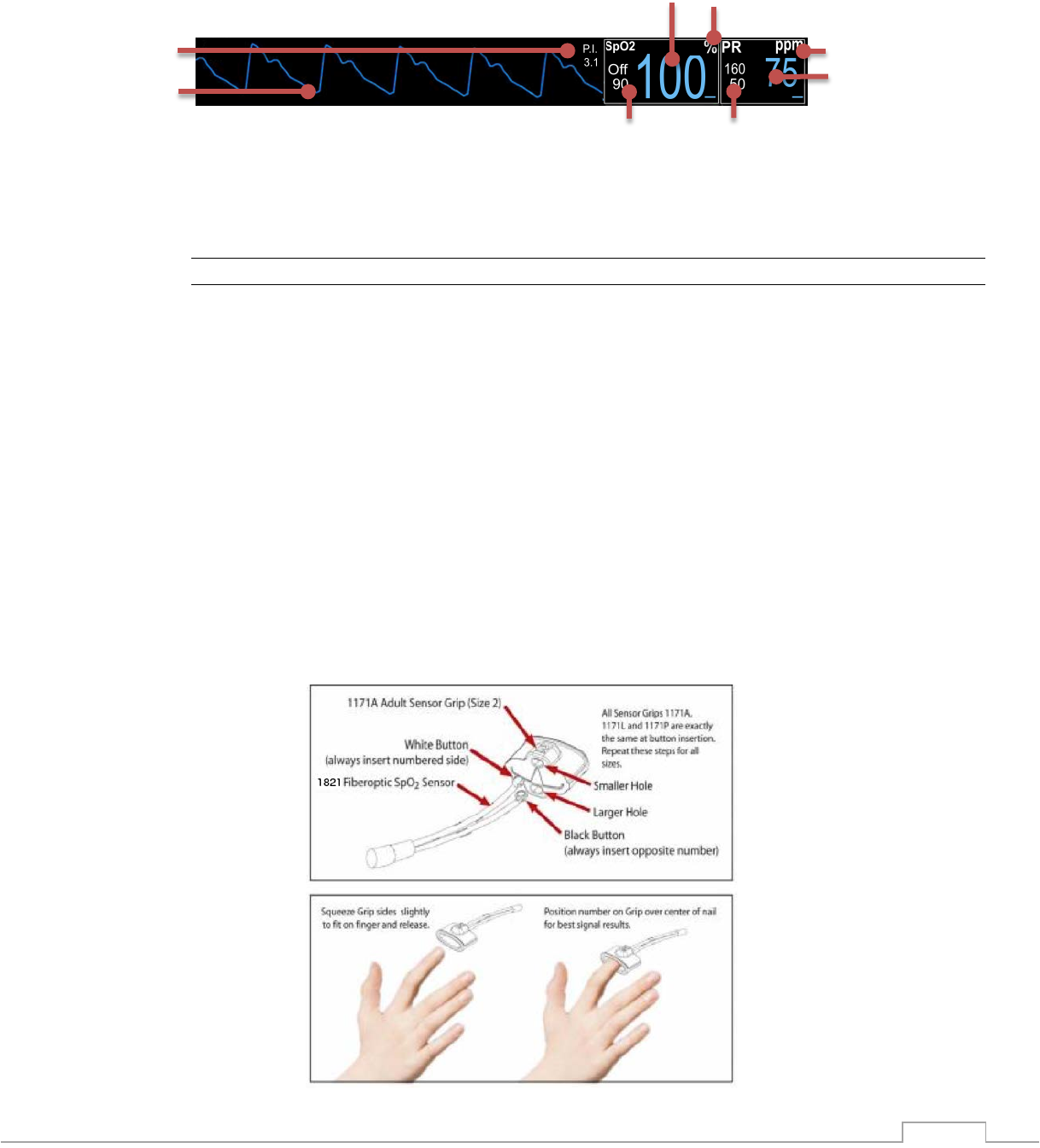
6.2.2. Understanding the Display
1. Measurement Unit
2. Current Vital Sign
3. Current Alarm Limits
4. SpO2 Pulsatile Waveform
5. Perfusion Index
NOTE
• The SpO2 waveform is normalized, and auto scaled to fit the waveform display
6.2.3. SpO2 Patient Application
6.2.3.1. Applying the Sensor
When selecting a sensor, consider the patient's finger / toe size and activity, adequacy of
perfusion, availability of sensor site and anticipated duration of monitoring. To apply the SpO2
sensor follow these steps:
1. Select the proper sensor attachment accessory for the patient
2. Remove any nail polish from the application site
3. Attach the appropriate applicator to the sensor
4. Carefully apply the adhesive or grip sensor to the patient
5. Check that the two SpO2 elements are directly opposite from each other and that no
external light is penetrating the site
6. Check perfusion index and make any necessary adjustments prior to starting a case
7. Route the cables in a straight line
8. Position the 3882 oPOD outside of the field of view (FOV), where possible.

6-13
NOTE
• Each sensor requires site-specific application procedures. The quality of the patient’s
pulse oximetry measurements and pulse signals may be adversely affected by certain
environmental factors, by oximetry sensor application errors, and by patient conditions.
Any of these factors can interfere with the ability to detect and display measurements
and may result in a loss-of-pulse condition. If the SpO2 measurement is questionable,
confirm the patient’s vital signs by alternate means and then check the pulse oximeter
for proper operation.
• Patients with anemia and/or significant concentrations of dysfunctional hemoglobins
(such as carboxyhemoglobin, methemoglobin, and sulphemoglobin) may appear to have
normal saturation values while actually being hypoxic. Further assessment, using
means other than pulse oximetry, is recommended for such patients.
• Poor SpO2 signal detection is indicated by a low PI (perfusion Index) value, and various
SpO2 messages.
6.2.3.2. Setup Checklist
• Only one oPOD with pulse oximetry sensor is used
• Correct SpO2 sensor attachment is selected for each patient size
• The sensor is completely dry after cleaning
• Sensor is positioned correctly to the patient
• SpO2 parameter is selected
• SpO2 is selected to be displayed through the Monitor Setup patient parameters menu
6.2.3.3. Testing SpO2 Alarm Functionality
• Place the SpO2 sensor with attachment on a finger and wait for the measurement value
to appear in the SpO2 vital sign display box.
• Remove finger from sensor
• Verify:
1. SpO2 Probe Off or Searching message appears in the alerts message area
2. SpO2 waveform flat lines
3. Alarm tone sounds
This completes the test of the alarm system
6.2.4. Changing SpO2 settings
6.2.4.1. Sweep Rate
The screen sweep rate setting determines the speed at with the SpO2 waveform traces moves
across the display. You can change the waveform sweep rate between 25 mm/s and 50 mm/s
by selecting the appropriate setting under the SpO2 menu.
To adjust the sweep rate follow these steps:
1. Touch the SpO2 vital sign box
2. Touch “Sweep Rate”
3. Select “25 mm/s” or “50 mm/s”
4. Touch Back button to close the menu
6.2.5. SpO2 Alarm Limits
Low Limit
Range
Default
Low
Default
High
High Limit
Range

6-14
Adult SpO2
Off, 50-99
90%
Off
70-99, Off
Pediatric SpO2
Off, 50-99
90%
Off
70-99, Off
Neonatal SpO2
Off, 50-99
85%
99%
70-99, Off
Adult Pulse Rate
Off, 30-239
50
120
50-240, Off
Pediatric Pulse Rate
Off, 30-239
75
180
50-240, Off
Neonatal Pulse Rate
Off, 30-239
90
200
50-240, Off
6.2.6. SpO2 Messaging
Message
Trigger Condition
SpO2 Inop
SpO2 hardware or software failure detected
SpO2 Searching
Searching for patient pulse
SpO2 Probe Off
Sensor is not properly attached to the patient
SpO2 Low Batt
15% of battery life is remaining in the oPOD
SpO2 Bad Probe
SpO2 sensor not compatible or damaged
SpO2 No Probe
SpO2 sensor is disconnected from the oPOD
Low Perfusion
Low perfusion detected

6-15
6.3. Respiration, Carbon Dioxide and Multi-Gas (Anesthetic Agents) Monitoring
Capnography (CO2) and Respiration or Capnography, Respiration and Multi-Gas Anesthetic
Agent sidestream options, can be equipped with the 3880. Both options feature automatic
barometric pressure compensation.
The CO2/Respiration only unit is a built in, integrated option to the 3880 MRI monitor unit and
operable to the full 30,000 gauss rating of the 3880. This built in CO2/Respiration only unit is
not for use with anesthetic agents as such gases may affect the accuracy of the CO2
measurements.
The Multi-Gas unit (P/N 3886) is a separate external unit to the 3880 monitor which connects to
the 3880 unit for display of CO2/Respiration, O2 (Fast Paramagnetic), N2O, and anesthetic
agents. The 3886 Multi-Gas unit is rated for up to 600 Gauss operation.
Side-stream gas analysis is a continuous, non-invasive technique for determining the
concentration of CO2 and other gases in the patient’s airway by measuring (non-dispersive)
absorption of infrared (IR) light of specific wavelengths. CO2 has its own IR absorption
characteristic and the amount of IR absorbed depends on the concentration of the sampled gas.
When a specific band of IR light is passed through respiratory gas samples, some of IR light will
be absorbed by the gas molecules. The amount of IR light transmitted after it has been passed
through the respiratory gas sample is measured with an IR detector. From the amount of IR
light measured, the concentration of gases is calculated. The built in CO2 only option utilizes
two IR filters, one for reference and one for detection of CO2.
With the Multi-Gas option, other gases, such as N2O, and anesthetic agent(s) likewise have
known specific IR absorption wavelengths. The Multi-Gas agent/N2O analyzer includes nine IR
filters for each of five agents, N2O, a CO2 specific filter and two reference filters. This allows the
detection and measurement of all seven gases via IR absorption. Please see Appendix E for
further technical details.
Respiration rate is the frequency of peak (end tidal) CO2 measurements per minute. A breath is
defined as a change in the CO2 signal which exceeds 1% (8 mmHg). All concentrations are
measured and displayed breath by breath.
! WARNING
• Do not measure CO2 or Multi-Gasses in the presence of aerosol pharmaceuticals.
• Anesthetic agents may be flammable and explosive. Use extreme caution and follow all
of your hospitals policy for working with and around Anesthetic Agents.
• Leakages in the sampling system or breathing circuit may cause the displayed values to
be significantly low.
• Nasal cannulas can display values significantly low when a patient is breathing through
the mouth.
• Always allow the system to warm up prior to connecting the sampling line and cannula
to the patient.
• Connect the scavenging exhaust tubing when patients receive inhalation anesthetics.
• Too high of a scavenge vacuum level can result in inaccurate readings or internal
damage.
• Mainstream cyclical pressure of 10 kPa can damage the 3880 since this system uses
sidestream technology as the measurement technique.
• Do not allow the tubing to become kinked or altered in a manner that would reduce flow.
• CO2 patient tubing and its associated components are intended for single-patient use

6-16
only. Do not clean or disinfect these items. Reuse of these items may lead to inaccurate
gas measurements or patient injury.
• Verify that the patient’s breathing efforts and timing coincide with the CO2 waveform on
the displays before completion of the patient setup.
• Always place the 3880 monitor in a well ventilated area. The calibration system
assumes that the ambient air will contain normal amounts of waveform CO2. If this
system is placed in an unventilated area that allows CO2 to accumulate, the result could
be inaccurate zeroing of the CO2 parameter resulting inaccurate patient readings.
• Use only IRadimed approved sampling lines and accessories. Other accessories lines
may cause inaccurate readings and malfunctions. Refer to section 9.
• Do not connect the scavenging exhaust line to the patient breathing circuit. Risk of
patient cross-infection may occur.
! CAUTION
• The accuracy of the data collected is greatly influenced by the proper use, fitting and
maintenance of the sampling tubing, and nasal cannula or airway adapter. All fittings
must be fitted together securely to keep them from separating during the procedure and
to ensure proper sampling without the introduction of outside air.
• The sample-line has a filter preventing bacterium, water and secretions from entering
the module. After a long-term use, dust or other substances may compromise the
performance of the filter or even block the airway. In this case, replace the sample-line.
It is recommended to replace the sample-line when it is found leaky, damaged or
contaminated.
• Always discard the sample-line when it becomes filled with fluid. Accidental fluid ingress
into the monitor can affect the gas measurements.
• Do not block the gas exhaust port. Inaccurate gas measurements could result.
• Remove sampling line from patient airway whenever nebulized medications are being
delivered.
• Do not over-tighten the sampling line connection. Over-tightening this connection may
cause permanent damage.
NOTE
• It is recommended that the sampling line be changed after each patient use, or every 10
hours per patient.
• An internal leak may result in condensation within the system. If this is suspected,
please contact IRadimed Technical Support.
6.3.1. Integrated CO2 Only Option Overview
The measurement provides:
1. A CO2 waveform (Capnogram).
2. EtCO2 and FiCO2 values: the EtCO2 value measured at the end of the expiration phase.
3. Airway respiration rate: the number of breaths per minute triggered from the CO2 waveform.
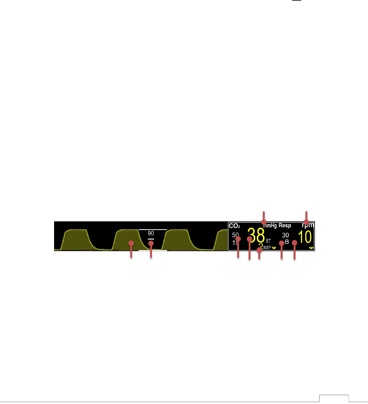
6-17
6.3.1.1. Sampling Lines
The IRadimed 3880 uses low maintenance and easy to apply sampling lines.
There are two basic types of sample lines. One type is via P/N 1842 A, P, or I type nasal
cannula. These cannula are to be used on non-ventilated/intubated patients not receiving
anesthetic agents, see 6.3.3.2. These nasal cannula will only mate with the built in CO2 only
option.
The second method is the P/N 1849 CO2/Agent Multi-Gas ‘Nomoline’ sample line for sampling
patient airway gases directly from intubated patients. This sample line will only mate with the
inlet connection of the Multi-Gas CO2/Agent Multi-Gas system of the 3865 option. See 6.3.3.1
Both types of sample lines are single patient use and include filters to prevent contaminates
from entering the gas measurement unit of the 3880 MRI Monitor system.
The sampling lines work as follows:
1. Patient gas sample enters sampling line from patient breathing via airway tap or nasal canula
circuit and passes through the gas sample line to the 3880 monitor
2. Gas sample is transported through the sample line and into the CO2 unit
3. Polymer absorbs water from the patient’s gas sample and evaporates it into surrounding air
4. Gas sample enters the IR cuvette where it is analyzed to accurately determine gas
concentration
6.3.1.2. Limitations
The following factors may influence the accuracy of measurement:
• Leaks or kinks in the line
• Mechanical shock
• Airway pressure
• Improper accessories for patients breathing style
6.3.2. Understanding the Display
1. CO2 Measurement Unit (%, mmHg or kPa)
2. Respiration Measurement Unit (rpm)
3. Current Respiration Rate Vital Sign value
4. Current Respiration Alarm Limits
5. Current EtCO2 Vital Sign value
6. Current EtCO2 Alarm Limits
7. Respiration Waveform
8. CO2 wave scale
9. Current inspired CO2 value
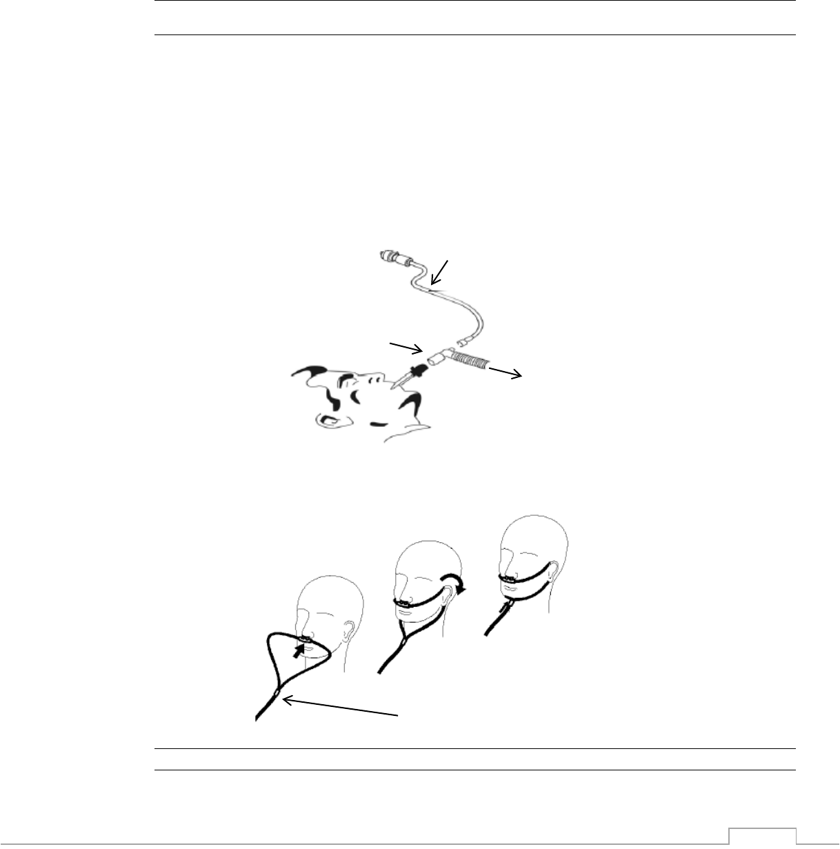
6-18
6.3.3. CO2 and Multi-Gas Patient Application
To apply the CO2 / Agent accessories follow these steps:
1. Ensure hardware is fully warmed up
2. Connect exhaust port of the monitor to the scavenge system using part number 1846
3. Connect an unused IRadimed sampling line to the 3880 CO2 gas inlet port
4. Connect the sampling line to either the airway adapter or in the case of nasal cannula, to
the in 6.3.3.1
5. Review the values for consistency with patient
! CAUTION
• In the patient’s sampling line can contain infectious elements, and can be a potential
hazard for the 3880 monitor user(s). Use caution when disconnecting and disposing of
used sampling lines.
• Always use the supplied microbial filter to keep biological and water condensate
contamination out of the monitor.
• Do not damage, separate or occlude sampling line
6.3.3.1. Intubated Patients, with use of airway adapter, suitable for all patients, with
or without anesthetic agents
6.3.3.2. Cannula Patients, use for CO2 measurement only, no agents
NOTE
Select size A, P, or I for best mechanical fit to patient nasal size.
P/N 1849 Sample line,
Nomoline, mates only with
P/N 3886 CO2/Agents unit
To ventilator
Airway Adapter
P/N 1842 A, P, or I
Sample line

6-19
! WARNING
Nasal cannula (P/N 1842 A, P, or I)are not for use with anesthetic agents.
6.3.3.3. Setup Checklist
• Ensure 3880 is warmed up prior to connecting
• All connections are secure with no leaks or kinks
• A new cannula or sampling line is used with each patient. For neonatal patient select
suitable gas sampling line
• No residual of alcohol based disinfectants
• Inspect lines regularly during use
6.3.4. Changing Respiration Settings
6.3.4.1. Unit
The End Tidal CO2 vital sign can be displayed in either Vol %, mmHg or kPa units.
To adjust the pressure unit of measure follow these steps:
1. Touch the CO2 vital sign box
2. Select “Unit”
3. Make Selection
4. Touch Back button to close the menu
6.3.4.2. Scale
The scale feature enables you to adjust the amplitude of an CO2 waveform displayed.
To adjust the scale follow these steps:
1. Touch the CO2 vital sign box
2. Select “Scale”
3. Make Selection (40, 60 or 90)
4. Touch Back button to close the menu
6.3.4.3. Sweep Rate
The sweep rate setting determines the speed at with the CO2 waveform trace moves across the
display. You can change the waveform sweep rate between 3.12 mm/sec and 25 mm/sec by
selecting the appropriate setting under the CO2 menu.
To adjust the sweep speed follow these steps:
1. Touch the CO2 vital sign box
2. Select “Sweep Rate”
3. Select desired value
4. Touch Back button to close the menu

6-20
6.3.4.4. Zero Calibration (CO2/Agent Multi-Gas Unit Only)
The zero calibration eliminates the effect of baseline drift during CO2 measurement and
therefore maintains the accuracy of the CO2 measurements. The Zero calibration also re-
calibrates the optional O2 measurements to 21% ambient room air. Zero calibration is carried
out automatically when necessary.
You can also start a manual zero calibration by following these steps:
1. Touch the CO2 vital sign box
2. Select “Cal Zero”, note this key is non-functional and greyed out when Agents OFF
3. Touch Back button to close the menu
NOTE
• Disconnecting the patient airway may be required when performing a zero calibration.
Follow on screen prompt.
• Gas measurements will not be displayed during a zero calibration
6.3.5. EtCO2 Alarm Limits
Low Limit
Range
Default Low
Default High
High Limit
Range
Adult EtCO2
Off, 5-60
15 mmHg
50 mmHg
5-80, Off
Pediatric EtCO2
Off, 5-60
20 mmHg
50 mmHg
5-80, Off
Neonatal EtCO2
Off, 5-60
30 mmHg
45 mmHg
5-80, Off
Insp FiCO2
Off, 3-20
Off
25 mmHg
5-25, Off
6.3.6. Respiration Alarm Limits
Low Limit
Default
Low
Default
High
High Limit
Adult Respiration
Off, 3-120
8
30
4-120, Off
Pediatric Respiration
Off, 3-120
8
30
4-120, Off
Neonatal Respiration
Off, 3-120
30
100
4-120, Off
6.3.7. CO2 Messaging
Message
Trigger Condition
CO2 Inop
Hardware or software failure detected
CO2 Occlusion
Displayed when sampling line is occluded
CO2 Zeroing
Performing an automatic Zero (CO2/Agent Multi-Gas Unit only)
No Sample Line
CO2 sampling line is disconnected (CO2/Agent Multi-Gas Unit only)
CO2 Cal Error
Calibration error is detected
CO2 Over Scale
CO2 waveform beyond visible scale
Gas System Inop
Gas system malfunction

6-21
6.3.8. Multi-Gas (Anesthetic Agents) Option Overview, P/N 3886
(Not intended for neonatal use)
The Anesthetic Agent option determines the concentration of certain gases using the infrared
(IR) light absorption measurement. The gases that can be measured by the module absorb IR
light and the system can detect up to two agent concentrations greater than 0.1%. Each gas
has its own absorption characteristic. The gas is transported into a sample cell, and an optical
IR filter selects a specific band of IR light to pass through the gas. For multiple gas
measurements, there are multiple IR filters. The higher the concentration of gas in a given
volume the more IR light is absorbed. This means that higher concentration of IR absorbing gas
cause a lower transmission of IR light. The amount of IR light transmitted after it has been
passed through an IR absorbing gas is measured. From the amount of IR light measured, the
concentration of gas present can be calculated.
Oxygen is measured via paramagnetic phenomenon. See appendix E for full technical details.
The measurement provides:
1. An CO2 waveform.
2. End tidal CO2 value (EtCO2): the EtCO2 value measured at the end of the expiration phase.
3. Fraction of inspired CO2 (FiCO2): the smallest CO2 value measured during inspiration.
4. Airway respiration rate: the number of breaths per minute, calculated from the CO2 waveform.
5. Anesthetic Gases (Sevoflurane, Isoflurane, Dexflurane, Enflurane and Halothane).
6. Nitrous Oxide: N2O.
7. Inspired Oxygen: O2.
8. MAC - Minimum Alveolar Concentration.
! WARNING
• Whenever a patient is under anesthesia or connected to a ventilator, constant attention
by qualified medical personnel is needed.
• Continuous exposure to waste anesthetic gases (including halogenated agents and
nitrous oxide) is not recommended. Always attach the waste gas connection
scavenging/evacuation tubing. Avoid venting any waste anesthetic gas directly into the
room air as exposure to these gases above the recommended OHSA limits could result.
• Minimum alveolar concentration (MAC) values are empirical and are not absolute
values. The MAC values correspond to those of healthy adults and cannot be applied to
children. Age and other individual factors influencing the behavior of volatile agents are
not taken into account.
• Organic vapors (e.g. from cleaning agents) in the sampling line or room air may alter
anesthetic agent readings.
• Certain substances (e.g. acetone, methane, or similar hydrocarbons) can result in
inaccurate readings and a false mixed agent alarm.
• The use of inhalers or nebulizers can result in inaccurate readings and a false mixed
agent alarm.
• Alcohol in the patient’s breath may modify the anesthetic agent readings.
NOTE
• If questionable anesthetic agent gas measurements are observed, examine all gas
sampling line connections, and the anesthesia gas machine and/or vaporizer settings,
before adjusting anesthesia delivery.

6-22
6.3.8.1. Understanding the Agent Display
1. Measurement unit
2. Current gas label of detected gases
3. Current exhaled measurement of detected gases
4. Current inspired measurement of detected gases
6.3.8.2. MAC Values
Minimum alveolar concentration (MAC) is a standard for comparing the minimum concentration
of the inhalation agents in the alveoli. It is a basic index to indicate the depth of anesthesia. 1
MAC represents the end-tidal concentration of an agent (at sea level) that, in 50% of patients
will prevent movement in response to a painful stimulus.
Minimum alveolar concentration (MAC) coefficient values are listed below:
Agent
SEV
ISO
ENF
DES
HAL
N2O
1 MAC
2.05%
1.15%
1.7%
6.0%
0.75%
100%
NOTE
• Altitude, patient age and other individual factors are not considered in the formula below
The formula to calculate the MAC value from end tidal gas measurements is as follows:
MAC =
% Et(Agent 1)
+
% Et(Agent 2)
+
% Et(N20)
X (Agent 1)
X (Agent 2)
100
! WARNING
• MAC values are empirical, not absolute values. The MAC values correspond to those of
healthy adults. Age and other individual factors influencing the behavior of volatile
agents are not taken into account.
6.3.8.3. Scavenging
When administering anesthetic agents always connect the scavenge line, P/N 1846, per
hospital policy to the exhaust port of the 3880 monitor. The respiratory gas exhaust is on the
right side panel of the monitor unit. Use a vented scavenge P/N 1846 line with less than
30mBar suction.
6.3.8.4. Oxygen Sensor
The 3880 system utilizes para-magnetic technology for the oxygen sensor providing. This
technology provides breath by breath FiO2.

6-23
6.3.8.5. Limitations
The following factors may affect the accuracy of measurement:
• Leaks or kinks in the line
• Mechanical shock
• Airway pressure
• Improper accessories for patients breathing style
6.3.9. Alarm Limits, Multi-Gas
Low Limit
Range
Default
Low
Default
High
High Limit
Range
O2
Off, 15-99
18%
88%
16-99, Off
N2O
Off, 3-60
OFF
80%
5-80, Off
Insp Hal
Off, 0.1-8.0
OFF
2%
0.1-8.0, Off
Et Hal
Off, 0.1-8.0
OFF
1.6%
0.1-8.0, Off
Insp Iso
Off, 0.1-8.0
OFF
3%
0.1-8.0, Off
Et Iso
Off, 0.1-8.0
OFF
2.5%
0.1-8.0, Off
Insp Enf
Off, 0.1-8.0
OFF
4%
0.1-8.0, Off
Et Enf
Off, 0.1-8.0
OFF
3.3%
0.1-8.0, Off
Insp Sev
Off, 0.1-10.0
OFF
6%
0.1-10.0, Off
Et Sev
Off, 0.1-10.0
OFF
5.0%
0.1-10.0, Off
Insp Des
Off, 0.1-22.0
OFF
15%
0.1-22.0, Off
Et Des
Off, 0.1-22.0
OFF
10.0%
0.1-22.0, Off
6.3.10. Agent and Gas Messaging, LEGI indicator
Message
Trigger Condition
CO2 Occlusion
Displayed when sampling line is occluded, LEGI Blinking Red
CO2 Zeroing
Performing an automatic Zero, LEGI Blinking Green
Mag Field High
Agent bench magnetic field limitation surpassed, LEGI RED
Gas System Inop
Hardware or software failure detected, LEGI Red
Anesthetic Agent Present
Agent Unit Connecting
Display of Agent ID and Concentration, LEGI Blue
Communications between 3880 to 3886 is being attempted

6-24
6.4. Non Invasive Blood Pressure Monitoring
This monitor uses the oscillometric method for measuring non-invasive blood pressure (NIBP).
This measurement can be used for adults, pediatrics and neonates, however to clarify, for
purposes of NIBP operation, the term “Pediatrics” does not include neonates. The oscillometric
technique applies specific algorithmic adaptations for neonatal cuffs and pulse levels. While
adult and pediatric patients (excluding neonates) share the same algorithmic settings for cuff
and pulse signal ranges. There is a range of cuff sizes offered for neonatal patients (four
sizes), all labeled for neonates. Patients with larger limbs than the neonatal types fit, will use
the larger sizes and operate in the Adult pediatric range. See section 9.
Automatic non-invasive blood pressure monitoring uses the oscillometric method of
measurement. This principle does not use sounds, but rather measures cuff pressure
oscillation amplitudes created by blood pulsations which vary as external cuff pressure passes
from above systolic to below diastolic. Oscillations are caused by blood pressure pulses against
the cuff with the largest oscillation signal by definition occurring when the cuff pressure equals
the mean arterial pressure (MAP). The systolic pressure is determined to be the cuff pressure
with an associated pulse amplitude of 72% of the maximum amplitude recorded at the MAP cuff
pressure, while diastolic is the cuff pressure associated with oscillations of 50% of the maximum
oscillation amplitude. The oscillation points for systolic and diastolic are empirically determined
and validated through testing.
In adult/Pediatric mode the initial inflation pressure is 160mmHG, while in Neonatal mode initial
inflation is 100mmHg. Subsequent pressure readings will use an inflation pressure of 30 above
the previously determined systolic pressure, or should no systolic be determined (patients
pressure too high as compared to the inflation pressure), inflation is 60mmHg above the MAP
reading. Further, in adult/pediatric mode only, there is an ability to increase inflation pressure,
during a given inflation cycle, should the algorithm determine that the patients systolic pressure
lies above the inflate pressure. In this case, cuff pressure will be increased to 40 mmHg above
the starting inflate pressure of this currently in process determination.
6.4.1. NIBP Overview
! WARNING
• Inaccurate measurements may be caused by incorrect cuff application or use. Make
sure the cuff is placed according to directions in this manual and the cuff directions for
use.
• Rapid, prolonged cycling of an oscillometric, noninvasive blood pressure monitor cuff
has been associated with any or all of the following: ischemia, purpura, or neuropathy.
Periodically observe the patient to make sure that their circulation is not impaired.
• Do not place the cuff on an extremity being used for intravenous infusion or any area
where circulation is compromised or has the potential to be compromised. As with all
automatically inflatable blood pressure devices, continual cuff measurements may
cause injury to the patient being monitored. Weigh the advantages of frequent
measurement against the risk of injury.
• Be sure to select the correct patient category setting for your patient before
measurement. Do not apply the adult/pediatric settings for neonatal patients.
• Artifacts from patient movement, common arrhythmias, premature beats, or fibrillation
may affect NIBP readings.
• Ensure the NIBP hose does not get kinked or occluded. Continuous NIBP cuff pressure
unable to be relieved may result in injury to the patient.
• Do not apply the blood pressure cuff to the same extremity as one to which a SpO2
sensor to an infusion or IBP catheter is attached. Cuff inflation can disrupt the infusion,
IBP or SpO2 monitoring and lead to alarms.