Iradimed IRM00 NON-MAGNETIC PATIENT MONITOR User Manual LiNQ Operation Manual
Iradimed Corporation NON-MAGNETIC PATIENT MONITOR LiNQ Operation Manual
Iradimed >
Contents
- 1. User Manual Part 1
- 2. User Manual Part 2
- 3. User Manual Part 3
User Manual Part 1
3880
MRI Patient Monitoring System
Operation Manual REF 1200

Non-Magnetic Patient Monitoring System, Model 3880
Operation Manual, Part Number 1200
Release 03/01/2017
© 2016/2017 IRadimed Corporation
IRadimedTM Corporation
1025 Willa Springs Drive
Winter Springs, Florida 32708 U.S.A.
Tel 407-677-8022 Fax 407-677-5037
www.iradimed.com
European Authorized Representative
Medical Device Consultancy
7 Pinewood Drive
Ashley Heath, Market Drayton,
Shropshire, UK, TF9 4PA
www.medicaldeviceconsultancy.co.uk
0843

I
Table of Contents
1. PREFACE ................................................................................................................. 1-1
1.1. About 3880 Non-Magnetic Patient Monitoring Systems ......................................... 1-1
1.1.1. Intended Use ................................................................................................ 1-1
1.1.2. Intended Audience ....................................................................................... 1-1
1.1.3. Equipment Classification and System Items ................................................. 1-1
1.1.4. Product Compliance ..................................................................................... 1-2
1.1.5. Intellectual Property...................................................................................... 1-3
1.1.6. Design Life Time .......................................................................................... 1-3
1.2. About this manual .................................................................................................. 1-3
1.2.1. Intellectual Property...................................................................................... 1-3
1.2.2. Manual Purpose ........................................................................................... 1-4
1.2.3. Illustrations ................................................................................................... 1-4
1.2.4. Printing History ............................................................................................. 1-4
1.2.5. Conventions ................................................................................................. 1-4
1.2.6. Product Availability ....................................................................................... 1-5
1.2.7. Warranty ...................................................................................................... 1-5
1.3. Warnings and Safety Precautions .......................................................................... 1-6
1.3.1. General ........................................................................................................ 1-6
1.3.2. MRI Monitor ................................................................................................. 1-7
1.3.3. Electrical Safety ........................................................................................... 1-8
1.3.4. MRI Use Precautions ................................................................................... 1-9
1.3.5. MRI Magnet Room (Zone IV) Placement ...................................................... 1-9
1.3.6. MRI Compatibility ......................................................................................... 1-9
1.3.7. Vital Sign Parameters ................................................................................. 1-10
1.3.8. USER RESPONSIBILITY ........................................................................... 1-15
1.3.9. Manufacturer’s Responsibility ..................................................................... 1-15
1.3.10. Safety Warnings Designation ..................................................................... 1-15
1.3.11. Disposal ..................................................................................................... 1-16
2. GETTING STARTED .............................................................................................. 2-17
2.1. About 3880 .......................................................................................................... 2-17
2.1.1. Introduction ................................................................................................ 2-17
2.1.2. System Hardware Overview ....................................................................... 2-18
2.1.3. 3880 Monitoring System Components........................................................ 2-20
2.1.4. User Interface Overview ............................................................................. 2-28
2.1.5. System Use Model ..................................................................................... 2-33
2.1.6. General Wireless Principles ....................................................................... 2-34
2.1.7. Wireless Commands .................................................................................. 2-35
2.1.8. MRI Conditions ........................................................................................... 2-35
2.1.9. Cleaning ..................................................................................................... 2-37
2.1.10. Repair ........................................................................................................ 2-37
2.2. Initial Setup .......................................................................................................... 2-38
2.2.1. Safety Precautions ..................................................................................... 2-38
2.2.2. Unpacking the System ............................................................................... 2-38
2.2.3. Visual Inspection ........................................................................................ 2-39
2.2.4. Functional Inspection ................................................................................. 2-39
2.2.5. Mounting .................................................................................................... 2-39
2.2.6. Choosing a location .................................................................................... 2-39

II
2.2.7. System Power ............................................................................................ 2-40
2.2.8. Antenna Strategies ..................................................................................... 2-44
2.2.9. Loading Recorder Paper ............................................................................ 2-45
2.2.10. Connecting Patient Accessories ................................................................. 2-47
2.2.11. User Interface ............................................................................................. 2-52
2.2.12. Setup Menu Overview ................................................................................ 2-55
2.3. Initial Use ............................................................................................................. 2-63
2.3.1. Wireless Communication ............................................................................ 2-63
2.3.2. Operating Modes ........................................................................................ 2-63
2.3.3. Patient Type ............................................................................................... 2-65
2.3.4. Filter Operation .......................................................................................... 2-66
3. ADVANCED CASE MANAGEMENT STRATEGIES ................................................ 3-1
3.1. Case Management ................................................................................................ 3-1
3.1.1. Preparing for a patient .................................................................................. 3-1
3.2. Multiple System Wireless Strategies ...................................................................... 3-1
3.3. Patient Transportation ........................................................................................... 3-2
4. USING ALARMS AND MESSAGES ......................................................................... 4-1
4.1. Alarm Categories ................................................................................................... 4-1
4.1.1. Physiological Alarms .................................................................................... 4-1
4.1.2. Technical Alarms .......................................................................................... 4-1
4.1.3. Messages ..................................................................................................... 4-1
4.1.4. Alarm Levels ................................................................................................ 4-3
4.2. Visual Alarm Indications ........................................................................................ 4-3
4.2.1. Alarm Identification ....................................................................................... 4-4
4.3. Alarm Functionality ................................................................................................ 4-7
4.3.1. Alarm Condition Delay .................................................................................. 4-7
4.3.2. Alarm Latching ............................................................................................. 4-7
4.3.3. Multiple Overlapping Alarms ........................................................................ 4-7
4.4. Controlling Alarms ................................................................................................. 4-8
4.4.1. Accessing Alarm Menu ................................................................................. 4-8
4.4.3. Enabling and Disabling Alarms ..................................................................... 4-9
4.4.4. Alarm Silence Button, Alarm Audio Off ......................................................... 4-9
5. USING TRENDS ....................................................................................................... 5-1
5.1. Overview ............................................................................................................... 5-1
5.2. Page Navigation .................................................................................................... 5-1
5.3. Trend Interval ........................................................................................................ 5-2
5.4. Clearing Trends ..................................................................................................... 5-2
5.5. Print Page .............................................................................................................. 5-2
6. USING VITAL SIGN PARAMETERS ........................................................................ 6-1
6.1. Cardiac Monitoring ................................................................................................ 6-1
6.1.1. ECG Overview ............................................................................................. 6-1
6.1.2. Understanding the Display ........................................................................... 6-3
6.1.3. ECG Patient Application ............................................................................... 6-4
6.1.4. Changing ECG Settings ............................................................................... 6-7
6.1.5. HR Alarm Limit Menu (Heart Rate form QRS detection of Trace A) ............. 6-9
6.1.6. ECG Messages ............................................................................................ 6-9
6.2. Pulse Oximetry Monitoring ..................................................................................... 6-9

III
6.2.1. Limitations .................................................................................................. 6-11
6.2.2. Understanding the Display ......................................................................... 6-12
6.2.3. SpO2 Patient Application ............................................................................ 6-12
6.2.4. Changing SpO2 settings ............................................................................. 6-13
6.2.5. SpO2 Alarm Limits ...................................................................................... 6-13
6.2.6. SpO2 Messaging ........................................................................................ 6-14
6.3. Respiration, Carbon Dioxide and Multi-Gas (Anesthetic Agents) Monitoring........ 6-15
6.3.1. Integrated CO2 Only Option Overview ........................................................ 6-16
6.3.2. Understanding the Display ......................................................................... 6-17
6.3.3. CO2 and Multi-Gas Patient Application ...................................................... 6-18
6.3.4. Changing Respiration Settings ................................................................... 6-19
6.3.5. EtCO2 Alarm Limits .................................................................................... 6-20
6.3.6. Respiration Alarm Limits ............................................................................ 6-20
6.3.7. CO2 Messaging .......................................................................................... 6-20
6.3.8. Multi-Gas (Anesthetic Agents) Option Overview, P/N 3886 (Not intended for
neonatal use) .......................................................................................................... 6-21
6.3.9. Alarm Limits, Multi-Gas .............................................................................. 6-23
6.3.10. Agent and Gas Messaging, LEGI indicator ................................................. 6-23
CO2 Occlusion ........................................................................................................ 6-23
Displayed when sampling line is occluded, LEGI Blinking Red................................ 6-23
6.4. Non Invasive Blood Pressure Monitoring ............................................................. 6-24
6.4.1. NIBP Overview ........................................................................................... 6-24
6.4.2. Understanding the Display ......................................................................... 6-25
6.4.3. NIBP Patient Application ............................................................................ 6-26
6.4.4. Changing Frequently Used NIBP Settings .................................................. 6-27
6.4.5. NIBP Alarm Limits ...................................................................................... 6-27
6.4.6. NIBP Messages ......................................................................................... 6-28
6.5. Temperature Monitoring ...................................................................................... 6-28
6.5.1. Temperature Overview ............................................................................... 6-28
6.5.2. Understanding the Display ......................................................................... 6-28
6.5.3. Temperature Patient Application ................................................................ 6-29
6.5.4. Changing the Temperature Settings ........................................................... 6-29
6.5.5. Temperature Alarm Limits, Celsius ............................................................ 6-30
6.5.6. Temperature Messaging ............................................................................ 6-30
6.5.7. Connecting the Sensor ............................................................................... 6-30
6.5.8. Temperature reference measurement ........................................................ 6-30
7. USING THE RECORDER ....................................................................................... 7-31
7.1. Loading Paper ..................................................................................................... 7-31
7.2. Recorder Setup Menu.......................................................................................... 7-31
7.2.1. Trace 1 ....................................................................................................... 7-31
7.2.2. Trace 2 ....................................................................................................... 7-31
7.2.3. Waveform Trace delay ............................................................................... 7-31
7.2.4. Auto Strip ................................................................................................... 7-32
7.2.5. Run Time ................................................................................................... 7-32
7.2.6. Recorder Sweep Speed ............................................................................. 7-32
7.2.7. To manually start a strip chart recording ...................................................... 7-32
7.2.8. Recorder Output ......................................................................................... 7-32
7.3. Printing ................................................................................................................ 7-32

IV
8. PRE-USE OPERATOR VERIFICATION, TROUBLESHOOTING AND USER
MAINTENANCE ............................................................................................................... 8-1
8.1. Overview ............................................................................................................... 8-1
8.1.1. Battery Life Expectancy ................................................................................ 8-1
8.1.2. Checking a Battery ....................................................................................... 8-2
8.2. Performance Checks ............................................................................................. 8-2
8.2.1. Daily in between tasks .................................................................................. 8-2
8.2.2. Regular Inspection and Verification .............................................................. 8-2
8.2.3. Every Twelve Months ................................................................................... 8-3
8.3. Service Setup Menu .............................................................................................. 8-3
8.3.1. Software Version .......................................................................................... 8-3
8.4. Care and Cleaning ................................................................................................. 8-4
8.4.1. Introduction .................................................................................................. 8-4
8.4.2. General Guidelines ...................................................................................... 8-4
8.4.3. Cleaning & Disinfecting ................................................................................ 8-5
8.4.4. Sterilizing ..................................................................................................... 8-5
8.4.5. Cleaning the Recorder Printhead ................................................................. 8-5
8.5. User Maintenance ................................................................................................. 8-6
8.5.1. Overview ...................................................................................................... 8-6
8.5.2. Updating Software ........................................................................................ 8-6
8.6. Troubleshooting Problems ..................................................................................... 8-6
8.7. Repair .................................................................................................................. 8-21
8.7.1. Overview .................................................................................................... 8-21
8.7.2. Changing Fuses ......................................................................................... 8-21
8.7.3. Removing a Paper Jam .............................................................................. 8-21
8.8. Warranty .............................................................................................................. 8-22
9. ACCESSORIES ........................................................................................................ 9-1
9.1. SpO2 ...................................................................................................................... 9-1
9.2. NIBP ...................................................................................................................... 9-1
9.3. ECG ...................................................................................................................... 9-2
9.4. CO2/Respiration Monitoring .................................................................................. 9-3
9.5. Multi-Gas (Agents) Monitoring ............................................................................... 9-3
9.6. Temperature .......................................................................................................... 9-3
9.7. Gating .................................................................................................................... 9-4
9.8. Power Supply ........................................................................................................ 9-4
9.9. Recorder ................................................................................................................ 9-4
10. EXHIBITS ............................................................................................................. 10-1
A. Specifications ...................................................................................................... 10-1
10.1. Overview ........................................................................................................ 10-1
10.1.1. Technical Specifications ............................................................................. 10-1
B. Messages, Alerts, Alarm Priority .......................................................................... 10-8
C. Repair ................................................................................................................ 10-10
D. Masimo SETTM Technology ............................................................................... 10-11
E. Internal CO2 Only, and Masimo Multi-Gas Systems Detail Operation ............... 10-14
E.1.1. Warnings and Cautions ............................................................................... 10-15
F. Symbol Conventions and meanings .................................................................. 10-27

1-1
1. Preface
1.1. About 3880 Non-Magnetic Patient Monitoring Systems
1.1.1. Intended Use
The IRadimed Corporation’s 3880 MRI Patient Monitoring System is intended to monitor a
single patient’s vital signs for patients undergoing Magnetic Resonance Imaging (MRI)
procedures.
The 3880 MRI Patient Monitoring System is intended for use by healthcare professionals.
The 3880 MRI Patient Monitoring System is intended for use in Adult, Pediatric, and Neonatal
populations for monitoring of Electrocardiogram (ECG), Non-Invasive Blood Pressure (NIBP),
Temperature, Pulse Oximetry (SpO2), Respiration, Capnography (CO2), Oxygen, and
Anesthetic Agents.
Patient types as identified herein regard pediatric patient types as not including neonates. The
definitions of pediatric patient types and associated ages is as below and per FDA guidance:
• Neonates: from birth through the first 28 days of life
• Infants: 29 days to less than 2 years
• Children: 2 years to less than 12 years
• Adolescents: aged 12 through 21 (up to but not including the 22nd birthday)
The 3886 Multi-Gas unit is intended for use in adult and pediatric populations, not including
neonates.
1.1.2. Intended Audience
This manual is intended for clinical professionals who are expected to have a working
knowledge of medical procedures, practices and terminology as required for radiology and the
monitoring of high acuity patients.
The 3880 MRI Patient monitoring system, the pulse oximeter oPOD and ECG ePOD are to be
operated by, or under the supervision of, qualified personnel only. The manual, accessories,
directions for use, all precautionary information, and specifications should be read before use.
1.1.3. Equipment Classification and System Items
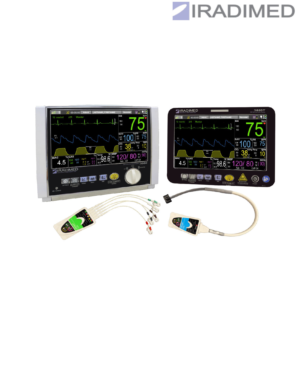
The 3880 MRI Patient Monitor System includes the following items:
3880 Monitor Unit
3881 ePOD ECG telemeter unit
3882 oPOD SpO2 telemeter unit
1120 Charger with cords and cable
1200 Operation Manual
Optional equipment includes:
3885-T Remote Control Tablet, Wireless (must be used with 3885-B)
3885-B Base Unit, Mains powered, Wireless Connect (must be used with 3885-T)
3886 Multi-Agent Gas Unit

1-2
Classification according to IEC 60601-1
Type of protection against electrical
shock
Class I ME Equipment – 3880, 3886
Note: 3881 and 3882 are Internally
powered Body Worn
Degree of protection against electrical
shock
Type CF (defibrillator-proof) equipment
for use in Patient Environment - 3880,
3886, 3881 ePOD, 3882 oPOD
Degree of protection against harmful
ingress of water and particulate matter
IPX1 enclosed equipment protected
against harmful effects of dripping water
per IEC 60529
Note: Optional 3885-B Base Station,
3885-T Remote Tablet and 3886 Multi-
Gas Unit are Ordinary Equipment
(enclosed equipment without protection
against ingress of water) used outside of
Patient Environment
Methods of Sterilization or disinfection
Non-Sterilizable, Use of liquid surface
disinfectants only
Mode of Operation
Continuous Operation
Equipment not suitable for use in the presence of flammable anesthetic mixture
with air, oxygen or nitrous oxide.
1.1.4. Product Compliance
The 3880 Patient Monitor is classified in the following categories for compliance:
•
This equipment is RoHS and WEEE compliant.
•
This equipment is suitable for connection to public mains as defined in CISPR 11.
•
This Monitor conforms to general safety standard for medical devices to IEC 60601-1.
•
This Monitor conforms to EMC safety standard to IEC 60601-1-2.
•
This Monitor conforms to usability safety standard for medical devices to IEC 60601-1-6
and IEC 62366.
•
Software is developed in accordance with IEC 60601-1-4 and IEC 62304.
•
The application of risk management analysis to medical device conforms to ISO 14971.
•
The SpO2 Parameter conforms to IEC 80601-2-61.
•
The TEMP parameter conforms to IEC 80601-2-56.
•
The CO2 parameter conforms to IEC 80601-2-55.
•
This Monitor conforms to particular safety standard for multifunction patient monitoring
equipment to IEC 60601-2-49.
•
The ECG parameter conforms to IEC 60601-2-27, ANSI/AAMI EC13.
•
The NIBP parameter conforms to IEC 80601-2-30
•
The alarm systems of the Monitor conform to IEC 60601-1-8.
Radio Compliance
INDUSTRY CANADA COMPLIANCE STATEMENT:
•
This device complies with Industry Canada license‐exempt RSS standard(s). Operation
is subject to the following two conditions: (1) this device may not cause interference, and
(2) this device must accept any interference, including interference that may cause
undesired operation of the device.
•
Le présent appareil est conforme aux CNR d'Industrie Canada applicables aux
appareils radio exempts de licence. L'exploitation est autorisée aux deux
conditions suivantes : (1) l'appareil ne doit pas produire de brouillage, et (2)
l'utilisateur de l'appareil doit accepter tout brouillage radioélectrique subi, même si
le brouillage est susceptible d'en compromettre le fonctionnement.

1-3
FCC COMPLIANCE STATEMENT:
•
This device complies with part 15 of the FCC Rules. Operation is subject to the following
two conditions: (1) This device may not cause harmful interference, and (2) this device
must accept any interference received, including interference that may cause undesired
operation.
Warning: Changes or modifications not expressly approved could void your authority to use this
equipment.
1.1.5. Intellectual Property
This device is covered under one or more of the following U.S. patents:
7,267,661 B2, 7,404,809 B2 and International Equivalents
7,553,295, 7,553,882, 8,105,282 B2 and International Equivalents
7,753,882; 8,150,493; 8,690,829; 8,262,642; 8,469,932; 8,105,282; 8,500,694 EP1530440;
1802362; 4597970; 5001845 International Patents; Other U.S. and International patents
pending.
Masimo Patent information and citations can be found at: www.masimo.com/patents.htm
Possession or purchase of this device does not convey any express or implied license to use
the device with unauthorized sensors or cables which would alone or in combination with this
device, fall within the scope of one or more of the patents relating to this device.
1.1.6. Design Life Time
The design lifetime of the 3880 MRI Patient Monitoring System units is six years.
1.2. About this manual
1.2.1. Intellectual Property
This document and the information contained in it is proprietary and confidential information of
IRadimed and may not be reproduced, copied in whole or in part, adapted, modified, disclosed
to others, or disseminated without the prior written permission of IRadimed. This document is
intended to be used by customers and is licensed to them as part of their IRadimed equipment
purchase. Use of this document by unauthorized persons is strictly prohibited.
1.2.1.1. Trademarks
IRadimed is a trademark of IRadimed Corporation. All other product and company names are
property of their respective owners. Masimo SET is a trademark of Masimo Corporation.
1.2.1.2. Copyright
1-4
Copyright © 2017, IRadimed. All rights reserved. Printed in USA.
1.2.2. Manual Purpose
This manual contains the instructions necessary to operate the product safely and in
accordance with its function and intended use. Observance of this manual is a prerequisite for
proper product performance and correct operation which ensures patient and operator safety.
This manual is based on the full configuration (including all optional features) and therefore
some content may not apply to your product. If you have any questions, please contact us.
This manual is an integral part of the product. It should always be kept close to the 3880
monitor so that it can be obtained conveniently when needed.
1.2.3. Illustrations
All images in this manual serve as examples only. They may not necessarily reflect the setup or
data displayed on your 3880 patient monitor.
1.2.4. Printing History
New editions of this document will incorporate all material updated since the previous edition.
Update packages may be issued between editions and contain replacement and additional
pages. Note that pages which are rearranged due to changes on a previous page are not
considered revised.
The documentation part number and revision indicate the current edition. The printing date
changes when a new revision is printed. (Minor corrections and updates which are incorporated
at reprint will not cause the date to change.) The document revision letter changes when
extensive technical changes are incorporated.
NOTE
• Specific menu screens may vary depending on software release being used.
1.2.5. Conventions
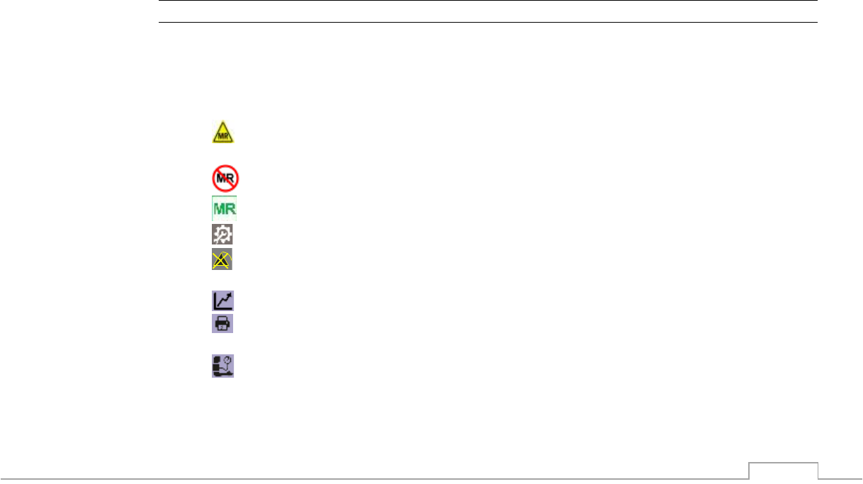
1.2.5.1. Symbols
• MR Conditional: An item that poses no known hazards in a specified MRI
environment with specified conditions.
• MR Unsafe: An item that is known to pose hazards in all MRI environments.
• MRI Safe: An item that poses no known hazards in all MRI environments.
• Settings button: Access monitor setup menus
• ALARM OFF - Standby button: Indefinitely pauses all alarms and terminates
automatic NIBP measurements
• Trend button: Trend Screen access and adjustment
• RECORD button: Starts strip chart recorder for hard copy printout at recorder in the
optional 3885-B Base Station
• NIBP START/STOP button: Initiates a NIBP measurement when one is not in
progress, or stops an NIBP in progress. Holding START/STOP button for 3 seconds
initiates STAT readings.
1-5
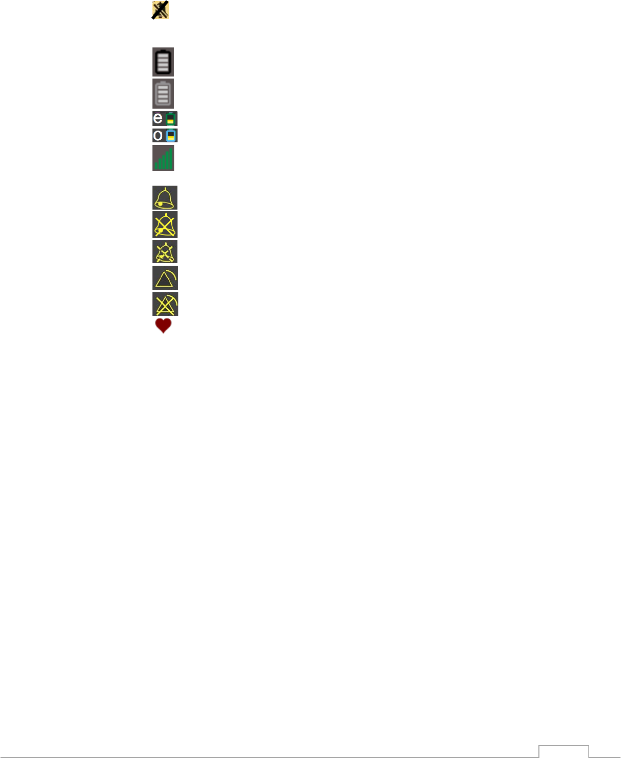
• AUDIO ALARM OFF – Alarm Silence button: multi-function audible alarm control,
resets sounding of alarm, pauses for 120 seconds the alarm sound, or re-enables alarm
sound capability.
• 3885-T Remote Tablet battery life
• 3880 Vital Signs Monitor battery life
• ECG ePOD battery life
• SpO2 oPOD battery life
• Wireless signal strength at 3880 Monitor, 3885-B Base Station, and 3885-T
Remote Tablet
• Alarm sound system is capable of audio sound triggered by alarms/alerts
• “Audio Alarm Off” ; ALARM conditions can visually indicate, if ALARM not OFF
• “Audio Alarm is Paused, with time countdown to reactivation indication
• ALARM condition is occurring
• ALARMS OFF, alarm conditions will NOT be indicated
• Heart beat detected
See Section F for more symbols and meanings
1.2.5.2. Definitions
• DSP – Digital Signal Processing is the manipulation of signals with the intention to
remove gradient induced noise on the vital sign waveforms.
• FOV – Imaging field of view
• Gating – Synchronizing the scanner image acquisition with the patients vital signs
• Latching – Alarm that, once activated requires deliberate user action to be deactivated.
• MAC - Minimum Alveolar Concentration is the alveolar concentration (end-tidal) of the
agent(s) at which 50% of individuals fail to move in response to a noxious or surgical
stimulus
• MRI Zones – American College of Radiology has defined four safety zones within MRI
facilities which correspond with levels of increasing magnetic field exposure.
• P.I. – Perfusion Index is a relative assessment of the pulse strength at the monitoring
site.
• RoHS – Restriction of Hazardous Substances directive on the restriction of the use of
certain substances in electronic equipment.
• WEEE – Waste Electrical and Electronic Equipment directive on the collection, recycling
and disposal of electronic equipment.
1.2.6. Product Availability
Some of the products mentioned in this manual may not be available in all countries. Please,
consult your local representative for the availability.
1.2.7. Warranty

1-6
IRadimed provides this document without warranty of any kind, implied or expressed, including,
but not limited to, the implied warranties of merchantability and fitness for a particular purpose.
IRadimed has taken care to ensure the accuracy of this document. However, IRadimed
assumes no liability for errors or omissions and reserves the right to make changes without
further notice to any products herein to improve reliability, function, or design. IRadimed may
make improvements or changes in the products or policies described in this document at any
time.
Refer to section 8.7 for detailed warranty information.
1.3. Warnings and Safety Precautions
1.3.1. General
The accuracy of the measurements can be affected by the position of the patient, the patient’s
physiological condition, and other factors. Always consult a physician for interpretation of
measurements made by this monitor.
Variation in measurements may be profound and may be affected by sampling technique as
well as the patient's physiological conditions. Any results exhibiting inconsistency with the
patient’s clinical status should be repeated and/or supplemented with additional test data. Blood
samples should be analyzed by laboratory instruments prior to clinical decision making to
completely understand the patient’s condition.
To avoid patient monitor fall, secure the monitor on a shelf or bracket outside of the 30,000
gauss magnetic field. Do not place the components of the 3880 MRI Patient monitoring system,
including pulse oximeter oPOD, ECG ePOD or accessories in any position that might cause it to
fall on the patient.
To ensure safety, avoid stacking multiple devices or placing anything on the device during
operation.
Explosion hazard: Do not use the 3880 MRI Patient monitor system including the pulse
oximeter oPOD, ECG ePOD, or accessories in the presence of flammable anesthetics or other
flammable substance in combination with air, oxygen-enriched environments, or nitrous oxide.
The operator should read and thoroughly understand this manual (Part Number 1200)
completely before attempting to operate the system.
Care should be taken when using the 3880 monitor with pregnant patients to ensure that the
device specifications are appropriate for the patient’s vital signs and anatomy. This device is not
intended for use with pre-eclamptic patients.
Fetal heart rates may be detected when monitoring pregnant patients.
Do not make modifications to this system. Modifications to the monitoring system and its
components which are not authorized by IRadimed Corporation can present a hazard to the
patient or user. Do not adjust, repair, open, disassemble, or modify the 3880 MRI Patient
monitor system components, including the pulse oximeter oPOD, ECG ePOD, or accessories.
Injury to personnel or equipment damage could occur. Return the device or its components for
servicing if necessary.
Use only accessories specifically designed and approved for use with the IRadimed 3880
system. Refer to section 9 for a complete list of available accessories.

1-7
• To protect against injury, follow the directions below:
o Avoid placing the device on surfaces with visible liquid spills.
o Do not soak or immerse the device in liquids.
o Do not attempt to sterilize the device.
o Use cleaning solutions only as instructed in this operator's manual.
Do not attempt to clean the device while monitoring a patient.
Do not submerge the pulse oximeter oPOD or ECG ePOD in any cleaning solution or attempt to
sterilize by autoclave, irradiation, steam, gas, ethylene oxide or any other method. This will
seriously damage the pulse oximeter oPOD or ePOD.
Contraindication: Use of ECG monitoring is contraindicated on patients with conductive or
active implant devices, including pacemakers or electrical stimulators.
1.3.2. MRI Monitor
Perform operational checkout before each use. If monitor fails to function properly, refer to
qualified service personnel.
For safe and accurate operation and MRI compatibility, use only recommended IRadimed
Corporation patient electrodes, cabling, lead wires, cuffs, hoses, sensors, tubing, etc. A listing
of these can be found in the Accessory Listing within this manual, or by contacting IRadimed
Corporation directly.
For continued operation, always connect the monitor to AC Main Power through the 1120 AC
Power Supply when a Low Battery indication occurs. Failure to do this can lead to interruption
of monitoring.
The system may not conform to all performance specifications if stored or used outside the
environmental specifications identified in Exhibit A in the rear of this manual.
Do not apply any unnecessary pressure to the screen area of the monitor. Severe pressure
applied to this portion of the monitor could result in damage or failure of this screen.
All equipment not complying with IEC 60601-1 should be placed outside the patient
environment. Only connect IEC 60601-1 compliant equipment to this monitor. To avoid
potentially hazardous leakage currents, always check the summation of leakage currents when
several items of equipment are interconnected.
For proper equipment maintenance, perform the service procedures at the recommended
intervals as described in the monitor’s service manual.
Single use devices should never be reused. Risk of infection or inaccurate readings may result.
Do not use this system or accessories inside a hyperbaric oxygen chamber.
As with all medical equipment, carefully route patient cabling to reduce the possibility of patient
entanglement or strangulation.
Monitor is not intended for long-term data storage.
Do not press on the buttons or touchscreen with sharp or hard objects which could damage the
keys or screen. Use only finger tips with the buttons and screen. Do not place the 3880 MRI

1-8
Patient monitoring system or the pulse oximeter oPOD or ECG ePOD where the controls can
be changed by the patient. In the case of the oPOD and ePOD, instruct the patient not to
operate the controls.
Never connect a patients IV lines to any part of this monitor including gas and / or blood
pressure connections.
Dropping, or shock to the monitor, PODs, Tablet, battery packs, or other accessories could
result in damage and affect accuracy or safe operation. Refer the component to a qualified
service personnel for proper checkout if any of these conditions occur.
1.3.3. Electrical Safety
Electrical shock and flammability hazard: Before cleaning, always turn off the device and
disconnect from any power source.
To protect from electric shock, always remove the sensors and completely disconnect the pulse
oximeter oPOD and ECG ePOD before bathing the patient.
ePOD and oPOD are not to be connected with any other equipment than the 3880 Monitor Unit
POD charge bays. Patient connections cannot be maintained and must be disconnected when
charging.
If monitor becomes wet or any fluid accidentally spills on the 3880 monitor, disconnect the
power cord from the power supply, remove the battery pack, and have the 3880 monitor
serviced by an authorized service representative.
Shock hazard exists if operated without chassis cover. Refer servicing to qualified service
personnel only.
For continued protection against fire hazard, replace fuses with same type and rating only.
Do not use electrical power extension cords or additional Multiple Socket Outlets. Electrical
power extension cords may create a safety hazard by compromising the grounding integrity of
the monitor.
If the integrity of the earth conductor of the AC main power cable is in doubt, operate the
monitor on internal battery power until proper earth connection is confirmed.
Electrical Shock Hazard: Carry out periodic tests to verify that leakage currents of patient-
applied circuits and the system are within acceptable limits as specified by the applicable safety
standards. The summation of leakage currents must be checked and in compliance with IEC
60601-1 and UL60601-1. The system leakage current must be checked when connecting
external equipment to the system. When an event such as a component drop of approximately
1 meter or greater or a spillage of blood or other liquids occurs, retest before further use. Injury
to personnel could occur.
Do not operate the 3880 MRI Patient Monitor without the 1133 Battery in place, as touching the
patient and the circuitry in the battery compartment of the 3880 monitor simultaneously must be
avoided.
This monitor and its listed accessories may be safely powered by the voltages 100-120VAC and
220-240 VAC having a frequency of 50 or 60 Hz.
To minimize radio interference, other electrical equipment that emits radio frequency

1-9
transmissions, other than the MRI machine, should not be in close proximity to the 3800 MR
monitoring system or the pulse oximeter oPOD or ECG ePOD.
Connect only those 3880 system compatible items identified are section 1.1.3 and 9.
1.3.4. MRI Use Precautions
Certain components of this device will be affected by the magnetic and radio frequency fields
present in your MRI System. Confer with your MRI physicist and/or Radiology staff to identify
the proper placement and use areas for the monitor and its accessories, as defined on the
monitor or accessory labeling. Failure to properly place the monitor and its accessories in the
Magnet Room (Zone IV) may result in monitor failure, and possible patient or user injury.
Always position the 3880 MRI Monitor at, or outside, the 30,000 Gauss (3.0T) magnetic field of
the MRI system.
When using the 3885-T Remote Tablet always verify proper communication of the 3880 MRI
Monitor with the 3885-T Remote Tablet prior to patient use. Should communication with the
Remote Tablet be interrupted, maintain direct visual and audible contact with the 3880 monitor
unit.
1.3.5. MRI Magnet Room (Zone IV) Placement
The 3880 MRI Monitor may be used in conjunction with an optional remote control. The 3880
MRI Monitor is specially designed not to interfere with MRI operations and may be used inside
the MRI Magnet Room in any location at or outside the 30,000 Gauss (3.0T) Field of the MRI
System.
Always place the 3880 MRI Monitor so that your view of the screen and alarm light will remain
unobstructed during use.
Risk of RF burn. ECG Lead wires which become inadvertently looped during MRI act as
conductive lines for RF induced currents. When lead cables or other cables form a conductive
loop in contact with the patient's tissue, minor to severe burning can result.
The 3885-T Remote Tablet is not for use in Zone IV, though it can be exposed to up to a 15,000
Gauss field.
Avoid when possible and use care when using accessories inside the FOV. If artifact is present
then re-position the oPOD, ePOD or accessories.
Keep cables clear from moving parts. Cables can get pinched and damaged between the MRI
table and / or MRI bore causing a delay in monitoring.
1.3.6. MRI Compatibility
The MRI ECG electrode, and ECG Patient Lead Wires/Cable, are compatible with Magnetic
Resonance Imaging (MRI) Systems within the following guidelines:
•
MRI systems with static magnetic field strengths up to 3.0 Tesla.
•
Usable within the MRI system bore with a Specific Absorption Ratio (SAR) of up to 4.0
W/Kg (whole body average). Use with a higher SAR greatly increases the risk of patient
burns.
•
Non-Magnetic materials are used in the construction of these assemblies.

1-10
•
If scanned directly across the plane of the ECG electrode, a slight image distortion may be
seen at the skin surface where the electrode is positioned.
•
Keep the ECG ePod and SpO2 oPOD out of the image Field of View (FOV). If scanned
directly across the plane of either POD, image distortion may be seen where the POD(s)
are positioned.
Perform the following to minimize risk of RF burn:
1. Keep ePOD and ECG lead wires from pressing against the bore of the MR magnet.
2. RF burn risk increases when multiple sensors/cables are in use. Such combinations are
not recommended.
3. Should power levels greater than a SAR of 4 w/kg whole body average be used, the risk
of patient heating or burn greatly increases. As a result, monitoring of ECG at power
levels of greater than 4 W/Kg is not recommended for the general patient population.
Such monitoring should only be attempted on conscious patients with good temperature
reflex so they may warn the operator of excessive heat at the monitoring sites.
4. High RF energy may cause patient heating or burns. For scans with whole body average
SAR >2 W/Kg, follow best practices such as limiting scan time to 5 minutes and pausing
at least 3 minutes between scans to allow patient to cool.
1.3.7. Vital Sign Parameters
• To ensure that alarm limits are appropriate for the patient being monitored, check the limits
each time the 3800 MRI monitoring system is used.
1.3.7.1. ECG
For best ECG and Heart Rate monitoring, always select the optimum lead view which has the
least artifact and largest QRS complex being detected for monitoring use.
Failure to respond to a Lead Fail alarm will cause a lapse in your patient’s monitoring. Always
respond promptly to this and any other alarms.
MRI induced gradient or radiofrequency artifact can sometimes cause inaccurate heart rates.
Inspect the ECG waveform during MRI scanning if spurious heart rates are observed.
B0 (static) magnetic field artifact can present artificially-induced augmented T waves during
ECG monitoring. Due to the effects of the magnetic field on the moving blood of the patient,
follow the recommended ECG electrode placement to minimize this type of artifact.
An inoperative ECG is indicated by absence of an ECG trace. See section 2.2.12.4.2
Heart rate values may be adversely affected by cardiac arrhythmia, or by operation of electrical
stimulators.
Ensure that the IRadimed MRI electrodes and / or ePOD wire set do not come in contact with
any other conductive parts including Earth.
The 3880 patient monitor is not intended for use on patients with pacemakers or electrical
stimulators.

1-11
1.3.7.2. NIBP
Use only NIBP accessories approved for MRI use (See MRI Accessory list in Section 9).
When using the NIBP portion of this instrument to measure blood pressure, remember that the
patient’s blood pressure readings are not continuous, but are updated each time a blood
pressure measurement is taken. Set a shorter interval for more frequent updating of the
patient’s blood pressure.
Do not attach the NIBP cuff to a limb being used for infusion, therapy or an arterio-venous (A-V)
shunt. Cuff inflation can block infusions, therapy or shunt bypass, possibly causing harm to the
patient.
Frequent NIBP measurements can cause pooling of the blood in the limb (hemostasis), and
peripheral tissue/nerve damage. Allow sufficient time for blood recirculation to prevent pooling
of the blood in the limb.
Arrhythmic and/or erratic heart beats (or severe motion artifact, such as tremors or convulsions)
can result in inaccurate readings and/or prolonged measurements. If questionable readings are
obtained, re-check patient’s vital signs by alternate means before administering medication.
To prevent possible nerve damage to the limb, apply the NIBP cuff as recommended by current
American Heart Association (AHA) guidelines for blood pressure monitoring.
To ensure accurate and reliable measurements, use only recommended NIBP cuffs/hoses. For
best accuracy, use the appropriate cuff size for each patient as recommended by the current
American Heart Association (AHA) guidelines for blood pressure monitoring.
Always tighten the NIBP cuff air hose connections snugly into place for proper operation.
Avoid NIBP measurements on any limb with swelling (e.g. from lymphedema). Patient harm
and/or inaccurate measurements could result.
Routinely inspect the NIBP cuff and hose assemblies for proper attachment and orientation.
Replace any damaged cuff and/or hose assemblies with cracks, holes, tears, cuts, etc. that
could cause leaks in the system. If cuff and/or hose assemblies with damage which could result
in leaks are used, prolonged and/or inaccurate patient readings could result.
To prevent skin abrasion, apply and remove NIBP cuff carefully. Keep Velcro® (hook and latch)
retention areas away from the skin.
Always use recommended NIBP cuffs and hoses. Avoid compression or restriction of NIBP
hose.

1-12
1.3.7.3. SpO2
The pulse oximeter should not be used as the sole basis for medical decisions. It must be used
in conjunction with clinical signs and symptoms.
Do not start or operate the pulse oximeter unless the setup was verified to be correct.
Do not use the pulse oximeter if it appears or is suspected to be damaged.
Use only MRI compatible SpO2 accessories (See MRI Accessory list in Section 9).
Use only the Fiber-optic SpO2 sensors recommended by IRadimed Corporation. A listing of
these can be found in the Accessory List within this manual, or by contacting IRadimed
Corporation directly.
The Fiber-optic SpO2 sensors are constructed of fiber-optic glass and should always be
handled with care to prevent damage. Improper handling can reduce both the signal
transmission quality and the SpO2 measurement sensitivity. Improper handling can also shorten
the SpO2 sensor's useful life.
The pulse oximeter feature in this monitor is designed to display functional SpO2 values.
SpO2 is empirically calibrated in healthy adult volunteers with normal levels of
carboxyhemoglobin (COHb) and methemoglobin (MetHb).
The pulse oximeter pulsatile waveform is not proportional to the pulse amplitude, but adjusts the
waveform amplitude as needed for proper viewing.
Avoid placement of the SpO2 probe on the same limb with an inflated blood pressure cuff. Cuff
inflation could result in inaccurate readings and false alarm violations.
SpO2 monitoring requires the detection of valid pulses to correctly determine SpO2 and Heart
Rate values. During conditions of gross artifact, or in the absence of valid pulses, the SpO2 and
/ or pulse rate values may not be correct.
The SpO2 monitoring portion of this monitor is intended to measure arterial hemoglobin oxygen
saturation of functional hemoglobin (saturation of hemoglobin functionally available for
transporting oxygen in the arteries). Significant levels of dysfunctional hemoglobins, such as
carboxyhemoglobin or methemoglobin, may affect the accuracy of the measurement. Also,
Cardiogreen and other intravascular dyes may, depending on their concentration, affect the
accuracy of the SpO2 measurement.
Always shield the SpO2 sensor from extraneous incident light sources. Such extraneous light
can cause SpO2 reading or pulse detection errors.
Frequently inspect the SpO2 sensor site for possible pressure tissue necrosis during prolonged
monitoring. Reposition the sensor at least every 4 hours. Special care should be exercised
when tape is used to secure the sensor, as the stretch memory properties of most tapes can
easily apply unintended pressure to the sensor site.
The pulse oximeter is not an apnea monitor.
The pulse oximeter may be used during defibrillation, but this may affect the accuracy or
availability of the parameters and measurements.

1-13
The pulse oximeter may be used during electrocautery, but this may affect the accuracy or
availability of the parameters and measurements.
The pulse oximeter should not be used for arrhythmia analysis.
If using pulse oximetry during full body irradiation, other than in MRI, keep the sensor out of the
radiation field. If the sensor is exposed to the radiation, the reading might be inaccurate or the
device might read zero for the duration of the active irradiation period.
A functional tester cannot be used to assess the accuracy of the pulse oximeter.
High-intensity extreme lights (such as pulsating strobe lights) directed on the sensor, may not
allow the pulse oximeter to obtain vital sign readings.
At higher sensitivity settings, performance of the "SpO2 Probe Off" detection may be
compromised. If the device is in this setting and the sensor becomes dislodged from the patient,
the potential for false readings may occur due to environmental "noise" such as light, vibration,
and excessive air movement.
Do not loop the fiber optic sensor cabling into a tight coil or wrap around the device, as this can
damage the patient cabling.
1.3.7.4. CO2 Only and Multi-Gas Systems
The 3880 MRI Patient Monitoring system offers two methods of gas monitoring, consisting of an
integrated CO2/Respiration only option, and an external Multi-Gas (P/N 3886) option. The 3886
Multi-Gas Unit provides measurement of CO2/ Respiration, Fast ‘Parametric’ O2, N2O with
automatic identification and measurement of a two gas mixture of five possible anesthetic
agents. The unit is based upon the Masimo/Phasein ‘OR+’ sidestream gas analyzer. This unit
is intended to be located in magnetic fields of less than 600 Gauss, such as direct mounting to
an MR Anesthesia machine. See appendix E for more details of both methods of gas analysis.
The integrated CO2/Respiration only solution, utilizes a solid state gas detection system as well
as a non-magnetic piezo sampling pump, for operation to 30,000 Gauss. This CO2 only unit is
not for use with anesthetic agents.
The accessory items for the built in CO2/Respiration only option can be found in section 9.4,
with the accessories for use with the 3886 Multi-Gas Unit in section 9.5. The accessories have
different types of connections so that the Multi-Gas Unit accessories only can connect to the
3886 Multi-Gas Unit, while the CO2 only accessories can only mate with the built in CO2 only
option.
Always select the appropriate CO2 tubing set for the patient being monitored. Verify that the
patient’s breathing efforts and timing coincide with the monitor’s waveform before completion of
the patient set-up.
Frequently inspect the CO2 patient tubing for proper gas flow. Avoid kinking of the CO2 patient
tubing that can result in leaking, reduction, or cut-off of the sample gas flow. Inaccurate gas
measurements could result.
During gas monitoring, a water vapor evacuating tubing (Nafion) which is included in the gas
sample circuit, reduces water vapor content of the patient's exhaled breath.
For proper operation, check the CO2 calibration during routine service. Routine calibration

1-14
should not be required, but if the specified operation does not occur, have a qualified service
person recheck the calibration. Proper re-calibration can only be performed during factory
service.
Gas sampling patient tubing and associated components are intended for single-patient use
only. Avoid cleaning or disinfecting these items for reuse. Inaccurate gas measurements or
cross contamination could result.
To prevent inaccurate or missed readings, keep the CO2 patient tubing clear of any moving
mechanisms which may kink, cut or dislodge the patient tubing.
Avoid connecting the CO2 calibration gas canister to the monitor by any method other than with
the designated calibration tubing. Connecting by any other method could invalidate the
calibration, and/or damage the monitor.
The gas measurements are displayed within 1 second of when the gas was sampled internally
to the associated analyzer.
1.3.7.5. Other
When positioned upon an IV pole or mobile cart, always secure the wheel locks when placed
within the MRI Magnet Room (Zone IV).
This product, or any of its parts, should not be repaired other than in accordance with written
instructions provided by IRadimed Corporation, or altered without prior written approval of
IRadimed Corporation.
No parts of the 3880 Patient Monitoring System shall be serviced while they are in use with a
patient.
The user of this product shall have the sole responsibility for any malfunction which results from
improper use, faulty maintenance, improper repair, damage, or alteration by anyone other than
IRadimed Corporation, or its authorized service personnel.
This monitor is equipped with a demonstration mode which displays simulated electronic patient
data for training or demonstration purposes. Do not attach a patient to the monitor whenever
this simulation is present on the monitor display (“SIMULATION” can also be seen in the screen
center).
All monitor alarms are categorized as medium priority, unless otherwise specified.
The patient connector inputs for all parameters are protected against the use of a defibrillator by
internal circuitry, and when the recommended patient cables or accessories are used. Though
not intended for use with High Frequency Surgical Equipment, the use of this circuitry and the
recommended cables and accessories provided in section 9 protect against the hazards
resulting from use of high frequency surgical equipment.
This monitor should not be synchronized with a defibrillator.
There are no known electromagnetic or other hazardous interference between the monitor and
other devices. However, care should be taken to avoid the use of cellular phones or other
unintended radio-frequency transmitters in the proximity of the monitoring system.
This monitor is not intended to be used with exposure to Linear Accelerator beam.

1-15
This monitor, ECG ePOD(s), SpO2 oPOD(s), and the 3885-T Remote Tablet use lithium
polymer rechargeable batteries, which must be recycled, or disposed of properly. For proper
disposal methods, contact your local IRadimed Corporation representative or distributor.
1.3.8. USER RESPONSIBILITY
This product will perform in conformity with the description thereof contained in this operating
manual and accompanying labels and/or inserts, when assembled, operated, maintained, and
repaired in accordance with the instructions provided.
This product must be checked periodically for proper operation. A defective or questionable
product should not be used. Parts that are broken, missing, plainly worn, distorted, or
contaminated should be replaced immediately.
Should such repair or replacement become necessary, IRadimed Corporation recommends that
a telephone call or written request for service be made to the factory or nearest service center.
IRadimed’s toll free number is: 866-677-8022 or 407-677-8022, ask for technical assistance.
This product or any of its parts should not be repaired other than in accordance with written
instructions provided by IRadimed Corporation or altered without the prior written approval of
IRadimed.
The user of the product shall have the sole responsibility for any malfunction which results from
improper use, faulty maintenance, improper repair, damage, or alteration by anyone other than
IRadimed Corporation or IRadimed Corporation authorized service provider.
Users must confirm the intended values are displayed on the screen during setup and after any
changes.
1.3.9. Manufacturer’s Responsibility
This product will perform as intended only if:
•
The 3880 MRI monitoring system is used in accordance with the manufacturer’s
specification, recommendations, warnings and precautions.
•
The 3880 MRI monitoring system is installed, maintained and serviced in accordance with
the instructions provided in the related technical manuals.
•
Assembly operations, extensions, readjustments, modifications, or repairs are carried out
by persons authorized by IRadimed.
1.3.10. Safety Warnings Designation
1.3.10.1. Warning
! WARNING
• Indicates a potential hazard or unsafe practice that, if not avoided, could result in death
or serious injury.

1-16
1.3.10.2. Caution
! CAUTION
• Indicates a potential hazard or unsafe practice that, if not avoided, could result in minor
injury or product/property damage.
1.3.10.3. Note
NOTE
• Provides application tips or other useful or important information.
1.3.11. Disposal
! WARNING
To avoid contaminating or infecting personnel, the environment or other equipment, make sure
you disinfect and decontaminate appropriately before disposing of it in accordance with local
laws.
1.3.11.1. Waste
At the end of lifetime, the product and its accessories must be disposed of in compliance with
the guidelines regulating the disposal of such products. Never dispose of waste electrical and
electronic equipment as unsorted municipal waste. Remove potentially dangerous materials
(for example batteries) before disposal. Collect materials separately, so that it can be safely and
properly reused, treated, recycled, or recovered. If you have questions concerning disposal of
the product, please contact IRadimed Corporation or your local IRadimed representatives.
Disposal of product - Comply with local laws in the disposal of the device and/or its accessories.
1.3.11.2. Batteries
When a battery has visual signs of damage, or no longer holds 50% of rated capacity, it should
be replaced. Follow local laws for proper disposal of batteries.
! WARNING
Do not disassemble batteries, or dispose of them in fire, or cause them to short circuit. They
may ignite, explode, leak or heat up causing personal injury.
1.3.11.3. Electronics
The 3880 monitoring system, radio, and accessories are subject to strict disposal regulations for
user and environmental safety. Observe and adhere to all local regulations when disposing of
any electronic component.
1.3.11.4. Calibration Gases and Patient-Related Materials
The 3880 Monitoring System and its accessories are subject to strict disposal regulations for
user and environmental safety. Observe and adhere to all local regulations when disposing of
any containers of calibration gases, patient scavenged gases, and any other patient-related
accessories used during monitoring.

2-17
2. Getting Started
2.1. About 3880
2.1.1. Introduction
The 3880 system is a Non-Magnetic multi-parameter patient monitor to continuously monitor
patients throughout the entire MRI care cycle. The 3880 monitor is comprised of the 3880 MRI
Monitor, 3881 ePOD, 3882 oPOD and an optional 3885-T Remote Tablet with 3885-B Base
Station. Further options include, CO2, Temperature, and the 3886 Multi-Gas unit. The wireless
3880 solution is designed to be small, simple and light weight making it a practical intra-
department patient transportation monitor for the MRI suite. This system is not intended for
patient transportation between hospitals. The 3880 system is equipped to support an entire
nursing shift with greater than 8 hours of typical battery operation. The 3880 monitor is Non-
Magnetic* and its MRI specific accessories are intended for the harsh MRI examination
procedures and environment including ultra-high-field applications.
The 3880 patient monitoring solution utilizes non-magnetic wireless technology which improves
safety, usability and data connectivity. The system utilizes wireless ECG and SpO2 PODs which
simplify patient workflow and setup by reducing the potential for loops and sensor damage.
• Standard Features
1. Small portable design weighing approximately 8.9 lbs (4 Kg)
2. Non-Magnetic and MRI conditional multi-parameter monitor up to 30,000 Gauss
and 4 W/Kg whole body average SAR
3. 10 inch color touchscreen user interface to simplify operation and cleanliness
4. Integrated wireless ECG and SpO2 POD charging
5. Wireless ECG and SpO2 POD enabled
6. 2.4 GHz wireless communication enabled for optional remote viewing
7. Integrated non-invasive blood pressure monitoring
8. Masimo SET SpO2 monitoring
9. Integrated MRI system gating enabled
10. Tri-Color Alarm Dome Light
11. ECG waveform gradient removal algorithms
12. Minimum of 8 hour battery operation
13. Instant On system start (< 4 seconds)
* Magnetic field ≤ 30,000 Gauss (3.0T)
• Optional Features
1. Integrated Sidestream Capnography monitoring
2. Integrated Sidestream Capnography or external 3886 Multi-Gas CO2/Anesthetic
Agent monitoring
3. O2 monitoring, with Agent Unit
4. Integrated temperature monitoring
5. 10 inch color Touchscreen Tablet
6. Base station
7. Thermal Strip Chart Recorder
8. HDMI output
9. Mount for pole and bedrail operation
2-18
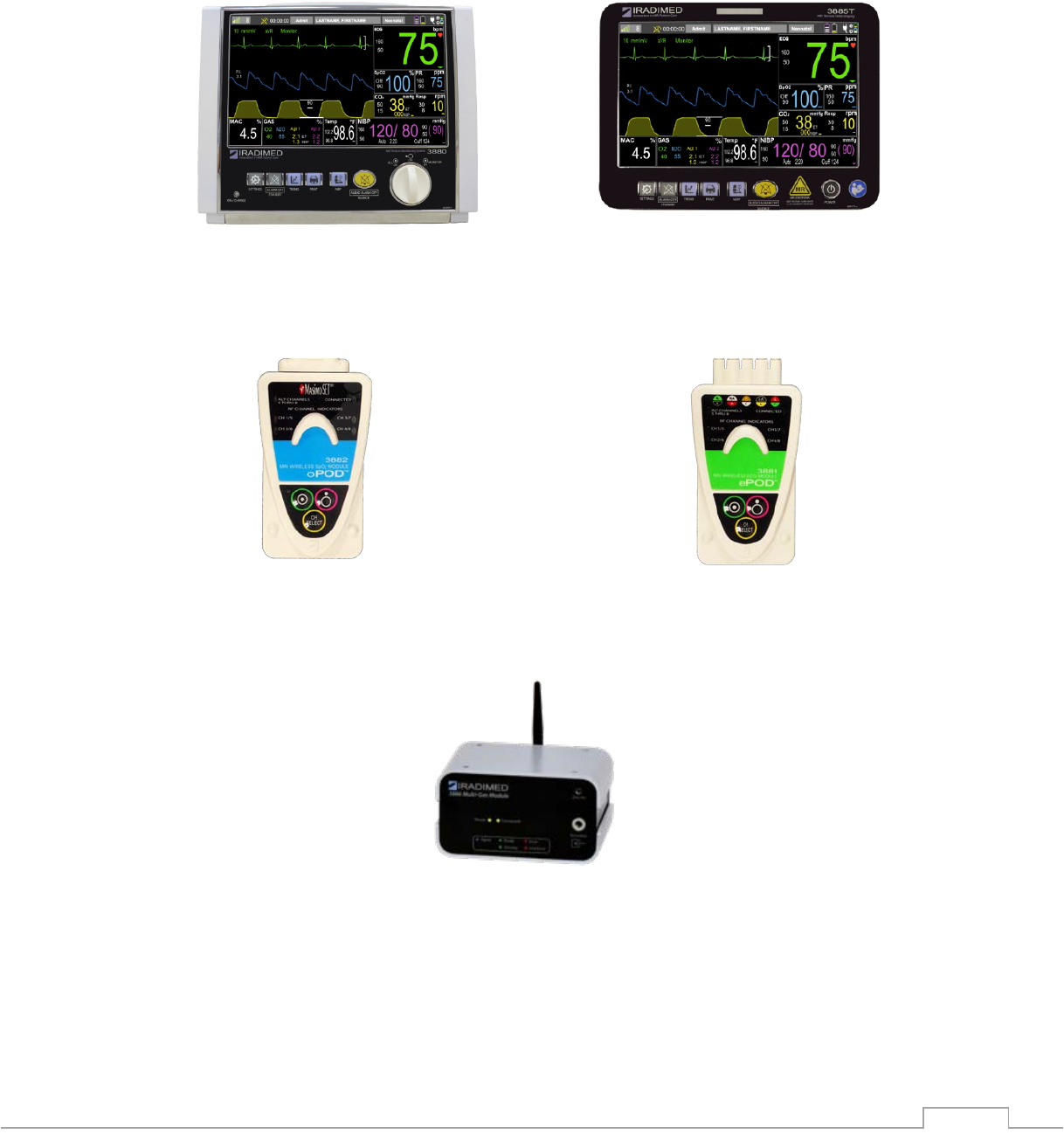
2.1.2. System Hardware Overview
2.1.2.1. System Hardware Components (accessories not shown)
3880 Non-Magnetic patient monitor
MR conditional to 30,000 Gauss
For use in MR magnet room
3885-T Remote Tablet (Optional)
MR conditional to 15,000 Gauss
For use outside MR magnet room
3882 Wireless SpO
2
oPOD
For patient monitoring in bore
MR conditional
to 30,000 Gauss
3881 Wireless ECG ePOD
For patient monitoring in
bore
3886 Wireless Multi-Gas Unit (Optional)
MR conditional to 600 Gauss
For use in MR magnet room
The 3880, 3881, 3882, and 3886 can be used in all zones. See section 2.1.8.
2-19
3885-B Base Station (Optional)
Base Unit acts as wireless repeater link
between 3880 monitor and 3885-T remote
tablet. Base also hosts the strip chart
recorder/printer.
MR “unsafe” for use outside MR magnet
room.
The 3885-B is for use only in Zone III.
See section 2.1.8.
2-20
2.1.3. 3880 Monitoring System Components
2.1.3.1. 3880 Multi-Parameter Monitor
The 3880 system is a small and portable Non-Magnetic multi-parameter patient monitor
designed for use when a large magnetic field such as a MRI system will be present during the
patient’s care cycle. The 3880 system is used to acquire, process, and display all vital sign
measurements during patient transport and during the MRI procedure.
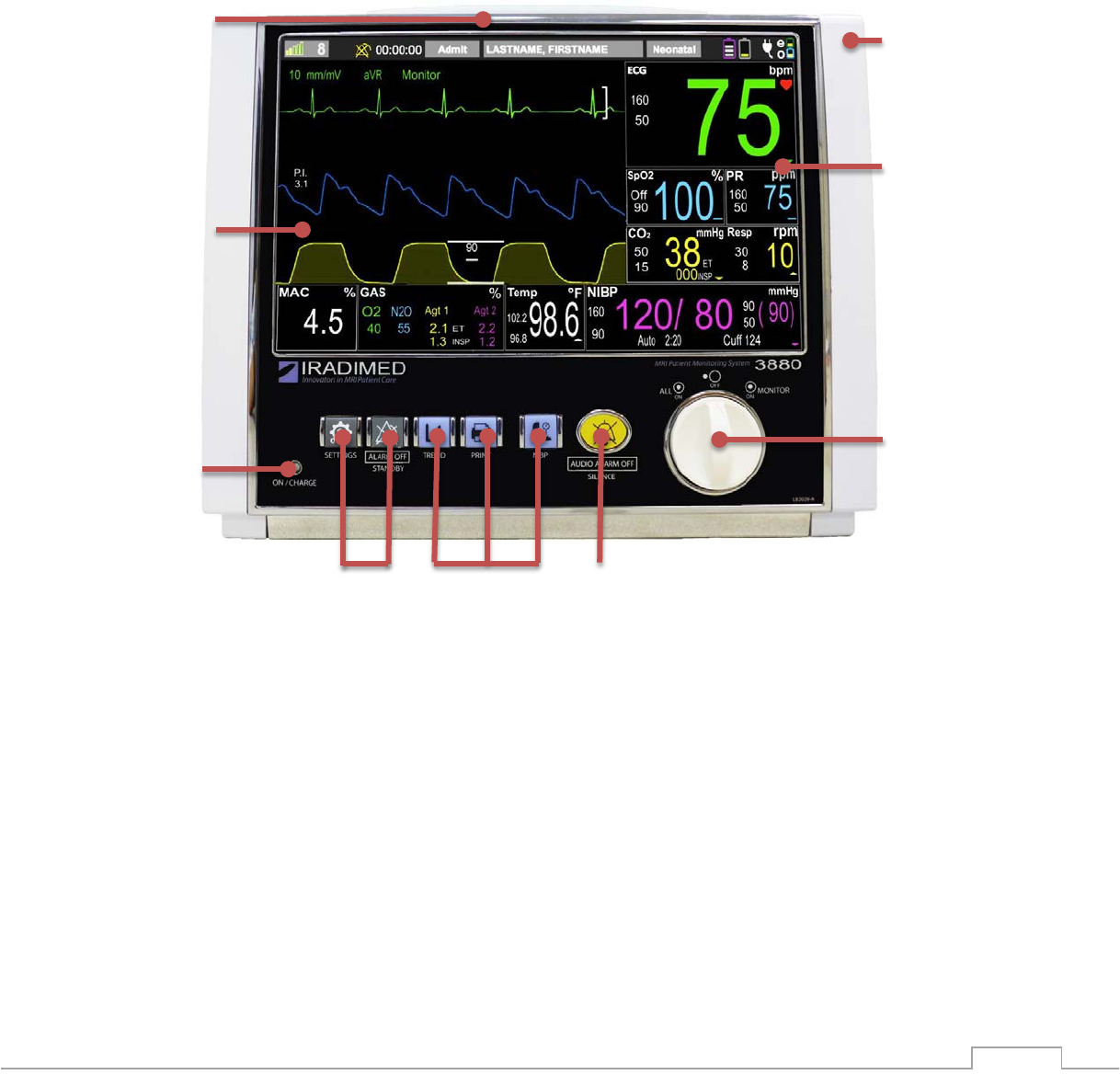
2.1.3.1.1 Front View
1. Lightweight, Nonmagnetic Case
2. Vital Sign Numerical Information Boxes
3. Power ON/OFF Dial, Clockwise Monitor only ON, Center Off, Counter clockwise All On
for Monitor and future Option Expansion Connector power on
4. Audio Alarm Off - Alarm Silence Button [AUDIO ALARM OFF]
5. Case Management Button: NIBP Start/Stop (Hold down to initiate STAT readings)
6. Case Management Button: Recorder Start/Stop (recorder optional with 3885-B)
7. Case Management Button: Trend Quick Access
8. Configuration Button: Monitor Standby [ALARM OFF] Mode ON/OFF
9. Configuration Button: Monitor Settings (Menus)
10. Mains Power/Charging LED Status
11. Touchscreen Display Interface
12. Tri-Color Alarm Dome Light
6
1
2
3
4
5
7
8
9
10
11
12
2-21
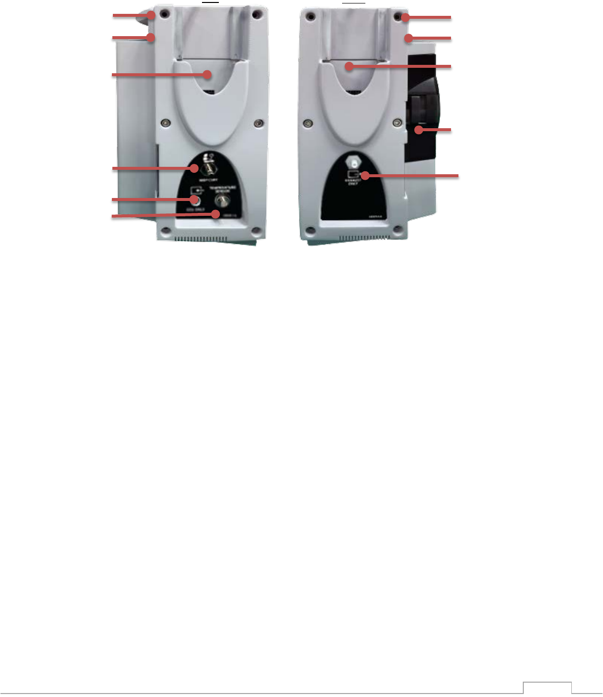
2.1.3.1.2 Side View
1. Handle
2. Cable Management Clip
3. ECG ePOD or SpO2 oPOD charging bay
4. User Replaceable Battery
5. Exhaust Scavenge Connection, Gas Outlet
6. Patient Vital Sign Connections: NIBP Port
7. Patient Vital Sign Connections: Built in CO2 Only Port, Gas Inlet
8. Patient Vital Sign Connections: Fiber optic Temperature Connector
1
3
4
3
1
6
2
2
Left
Right
7
8
5
2-22
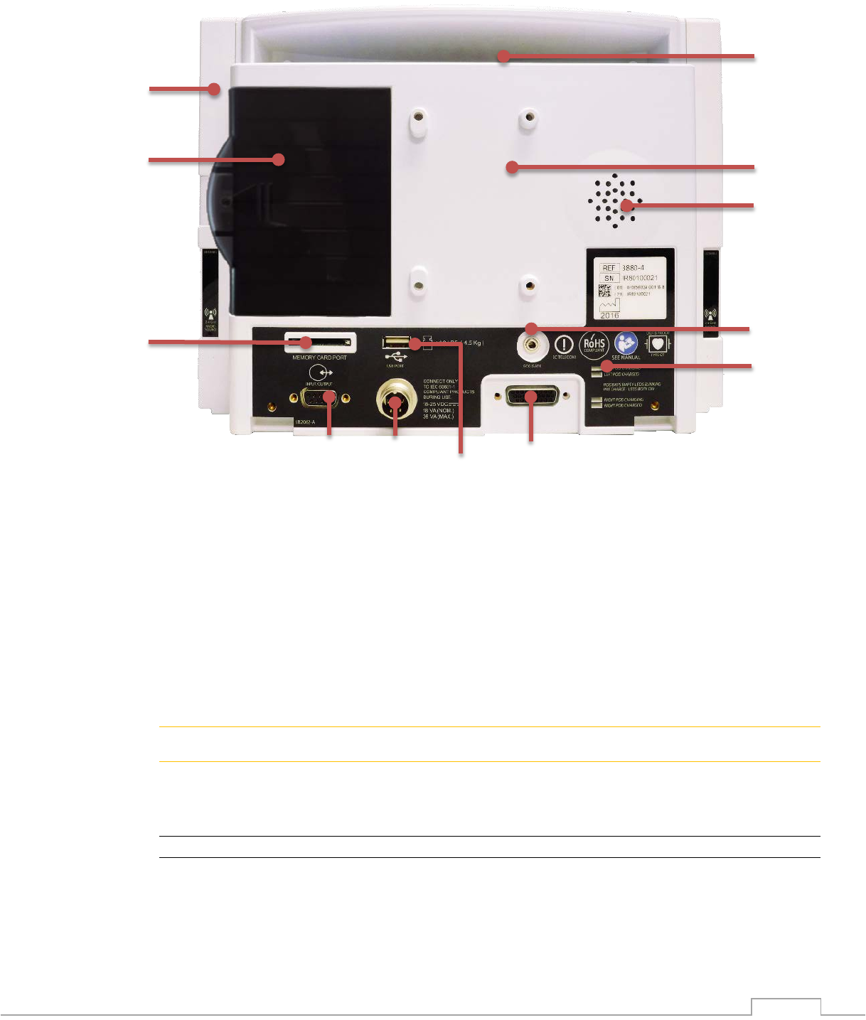
2.1.3.1.3 Rear View
1. Handle
2. Cable Management Clip
3. Flex Mount IV Pole / Bed Rail Mount
4. Speaker
5. Gating Output
6. POD Charging Status Indicator,
Blinking = No connection, Amber = Charging, Green = Charged
7. Future Option Expansion Connector
8. USB Port
9. Power Input, 19 VDC
10. Input / Output Connector, serial RS232
11. SD memory card slot
12. User Replaceable Battery
! WARNING
• Data I/O ports on the 3880 rear panel are not a PC-compatible computer format. Do not
connect any non-IRadimed accessory to these ports during patient use. Improper
monitoring operation could result. Refer to the service manual for specific port use.
NOTE
• Do not connect any non-IRadimed supplied devices or cabling to the connections on the
back of the 3880 as these connections do not provide electrical isolation.
• Any peripherals or serial cables connected to the data ports must be IEC 950 or IEC
60950 compliant.
• The 3880 uses a serial port (DB-9 female) for the external data output port. The monitor
uses a proprietary RS232 communication protocol.
1
3
2
12
4
5
9
10
7
11
8
6
2-23
• Remove any protective port covers prior to use.
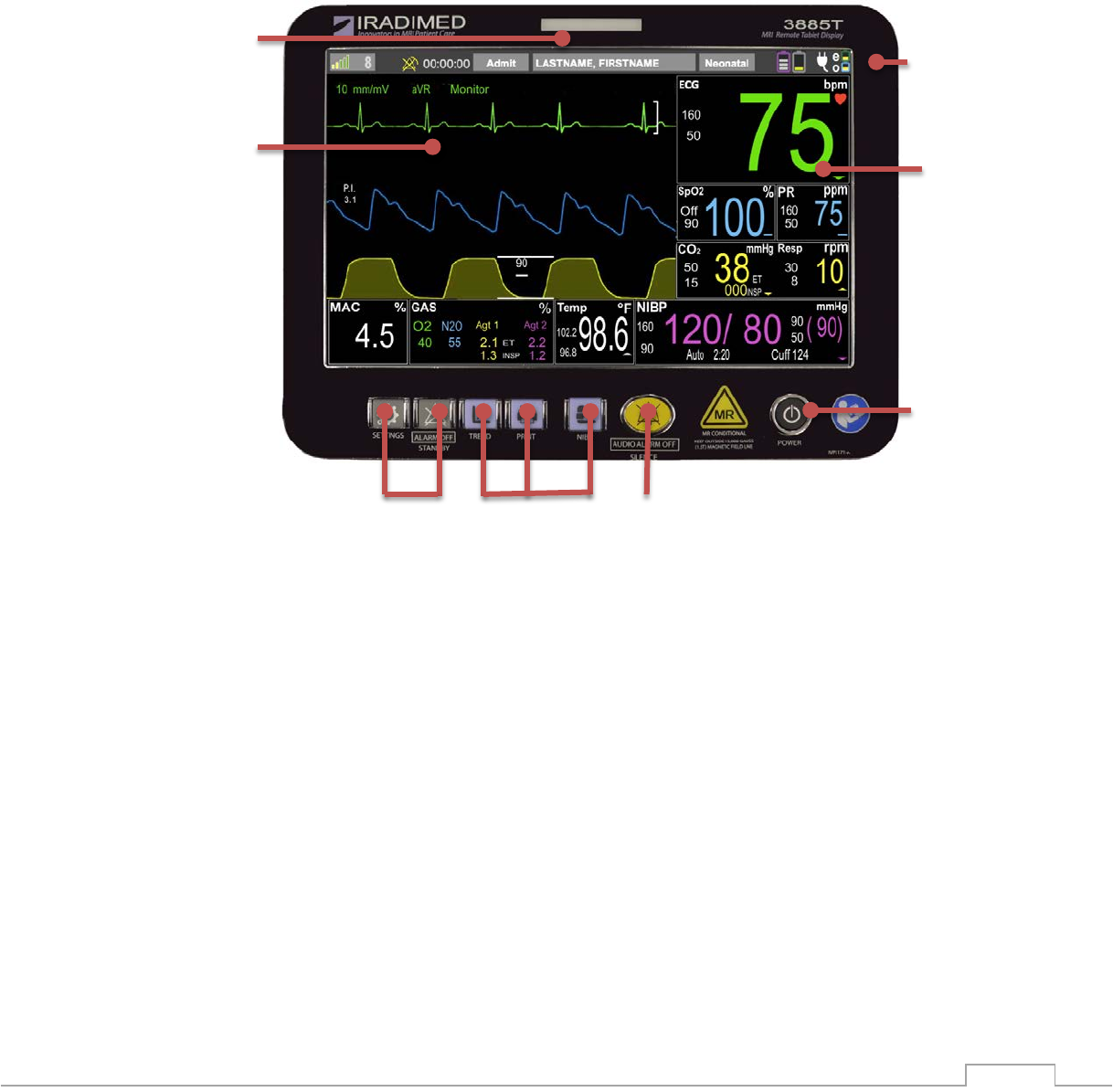
2.1.3.2. 3885-T Remote Tablet
The 3885-T optional Remote Tablet is a convenient user interface mirroring the 3880 Monitor
unit, to display, monitor, control and document the patient case. The 3885-T Remote Tablet is
non-magnetic up to 15,000 Gauss, but is not RF shielded for use inside of zone IV during
imaging. The 3885-T Remote Tablet has the following hardware features.
2.1.3.2.1 Front View
1. Non-Magnetic Case
2. Vital Sign Numerical Information Boxes
3. Power ON/OFF Button
4. Audio Alarm Off - Alarm Silence Button
5. Case Management Button: NIBP Start/Stop
6. Case Management Button: Recorder Start/Stop (recorder optional with 3885-B)
7. Case Management Button: Trend Quick Access
8. Configuration Button: Monitor Standby Mode ON/OFF
9. Configuration Button: Monitor Settings
10. Touchscreen Display Interface
11. Tri-Color Alarm Dome Light
6
1
2
3
4
5
7
8
9
10
11
2-24
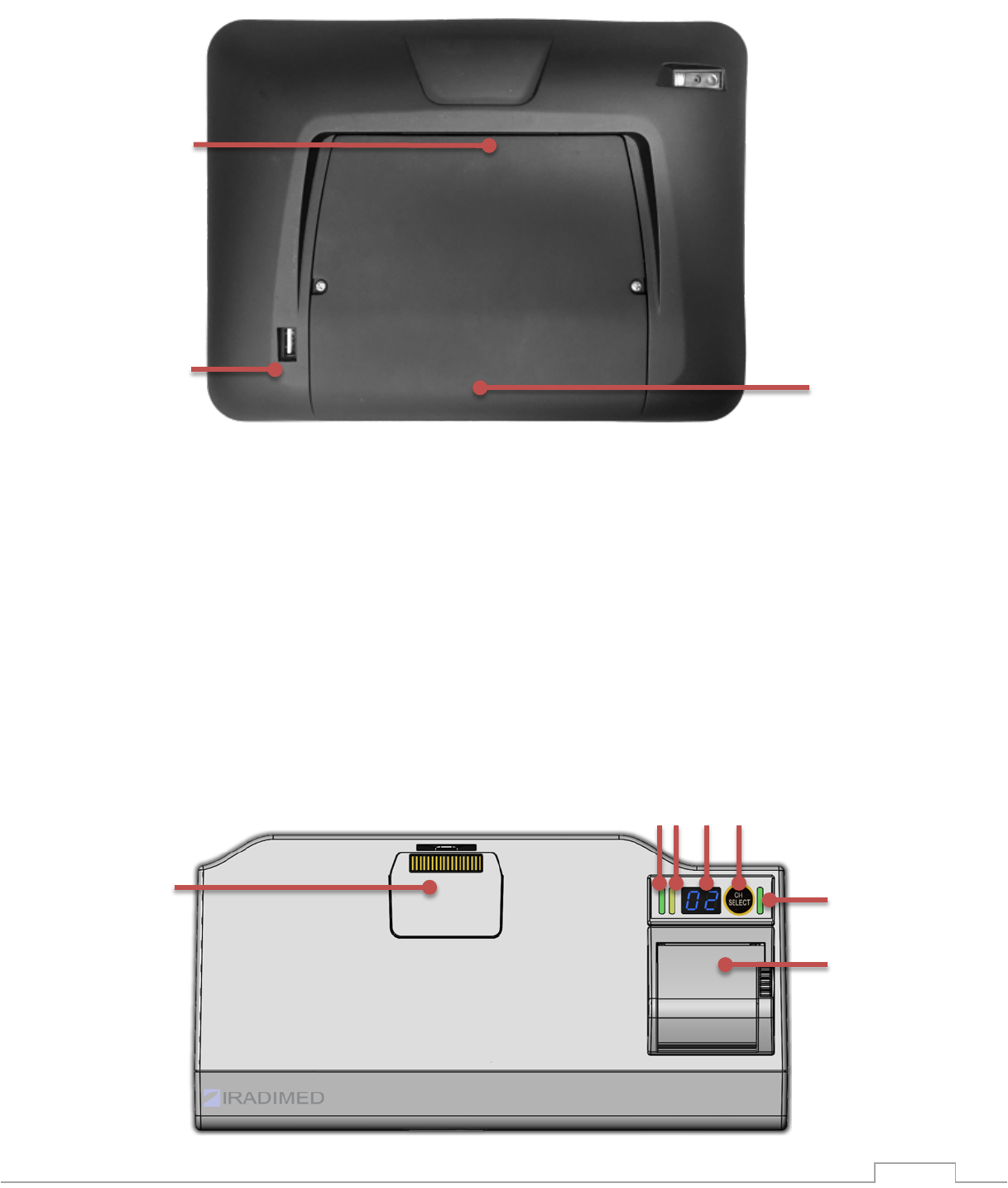
2.1.3.2.2 Remote Tablet Rear View
1. Replaceable Battery
2. USB Port
3. Base Station Dock
2.1.3.3. 3885-B Base Station
The 3885-B Base Station is the communication hub of the 3880 MRI Patient Monitoring System.
The Base Station is facilitates transfer of data through the MRI shielding, enabling wireless
communication between the 3880 Patient Monitoring System components during MRI
procedures. The Base Station also serves as a MRI Control room charging and strip chart
recording/printing station. Tablet and Base must always be on the SAME channel. To connect
a complete wireless system with the 3880 Monitor unit and ePOD / oPOD, all devices should be
on the same channel.
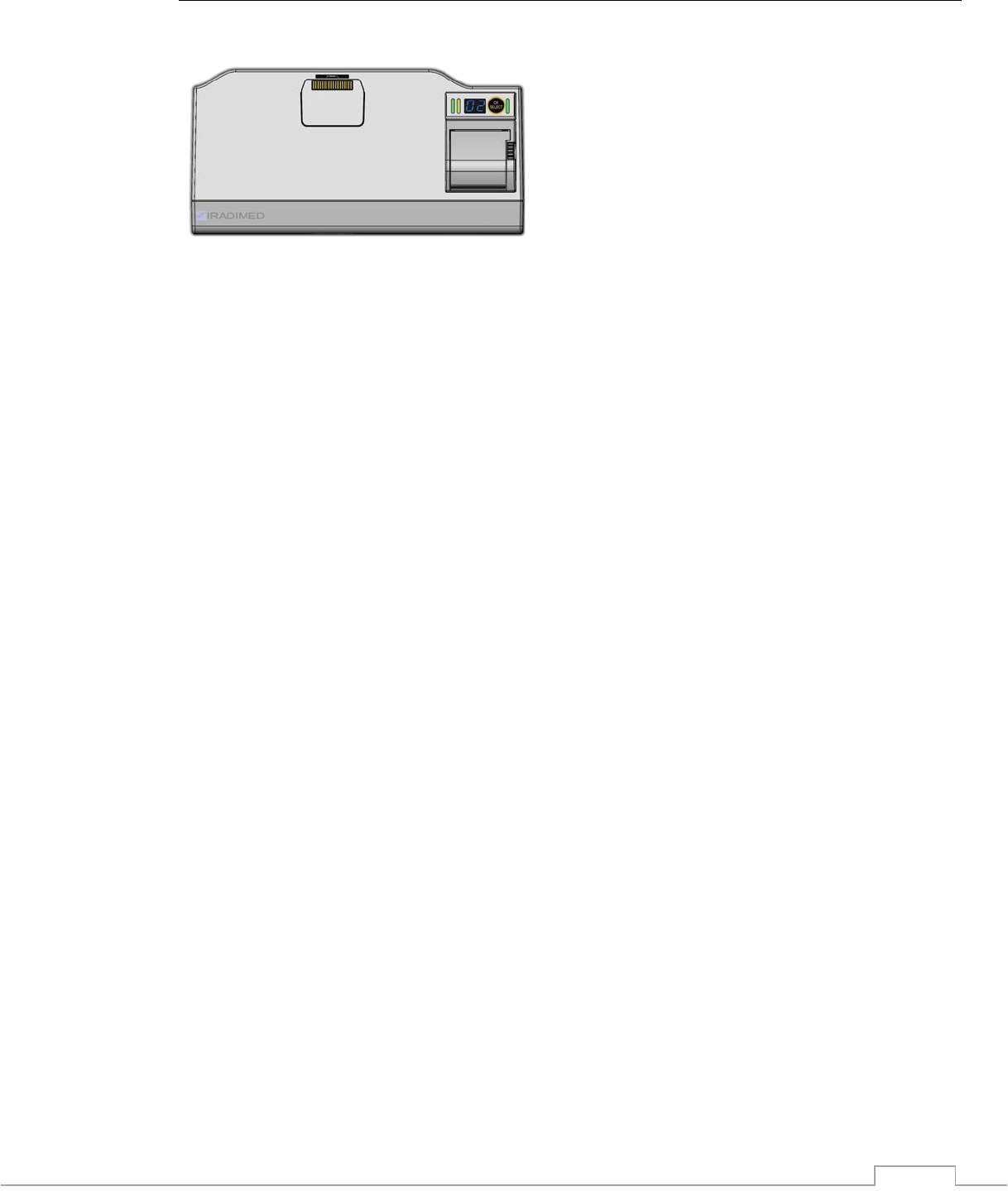
2.1.3.3.1 Front View
3
1
2
1
4
3
2 2
5
6
2-25
1. Power Status Indicator of the Base Station, Tablet Charge Indicator (Amber)
2. Charging Indicators for 1133 Battery Packs
3. Thermal Strip Chart Recorder/Printer
4. Tablet / Base Station Dock
5. Channel LED Indicator
6. Channel Select Button
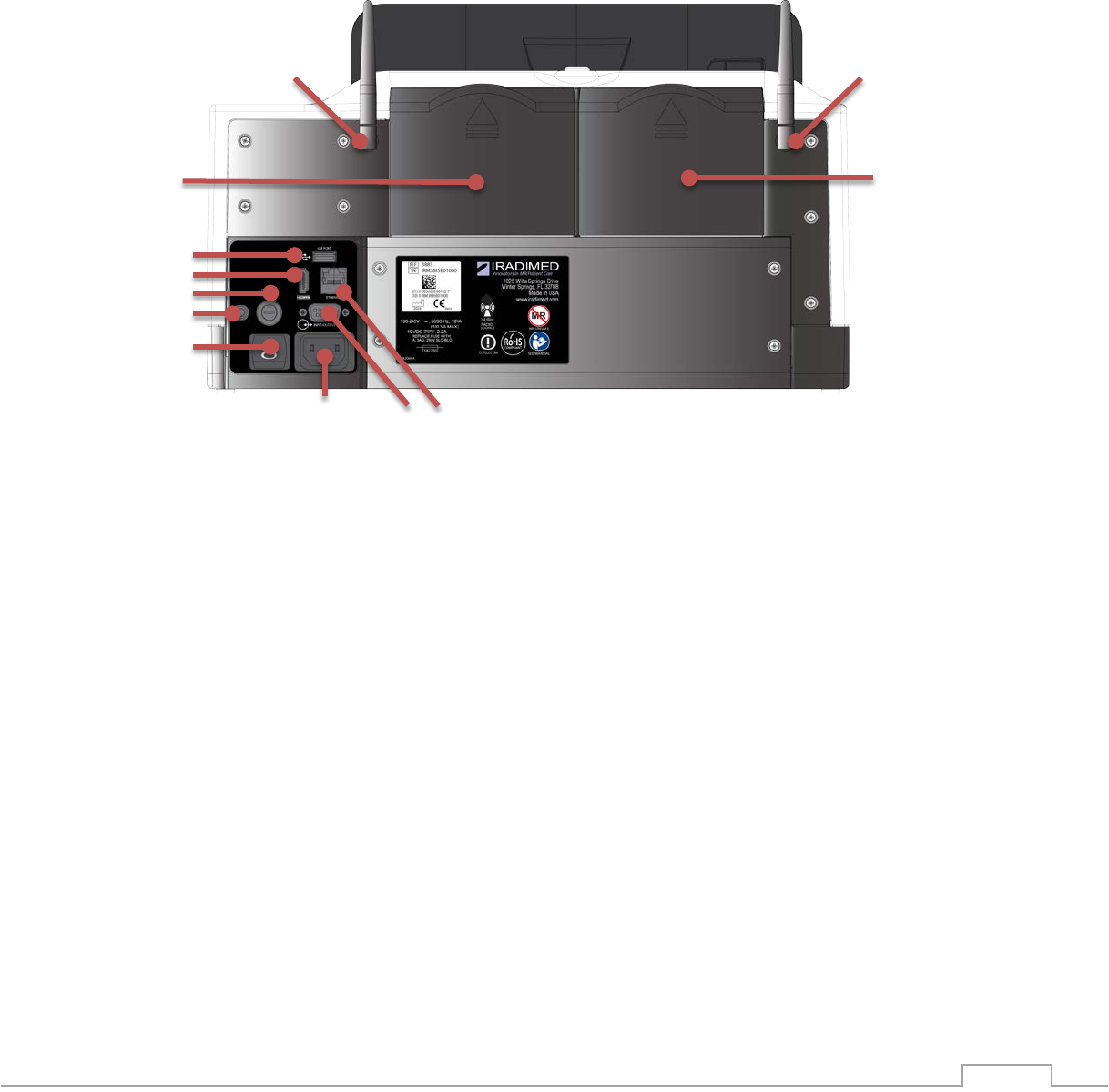
2.1.3.3.2 Rear View
1. 3880 Monitor unit Battery charging bay
2. Antenna Connectors:
2a MRI Room Zone IV antenna connection, Base/3880 monitor
2b Zone II and III 3885-T Tablet / 3885-B Base Station antenna
3. AC Power Receptacle
4. ON/OFF Mains Power Switch
5. Ground Terminal
6. Fuse
7. HDMI Output
8. USB Port
9. Ethernet Connector
10. I/O Port
4
3
1
1
2b
2a
5
6
7
8
9
10
2-26
2.1.3.3.3 Top View
1. 3880 Monitor unit Battery Charging Bay
2. Power LED status of the Base Station
3. Charging Indicators for 1133 Battery Packs
4. Thermal Strip Chart Recorder
5. Tablet / Base Station Dock
6. Tablet Lock
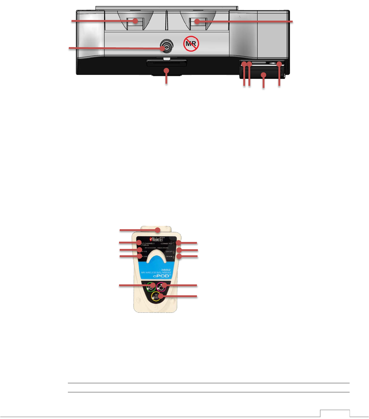
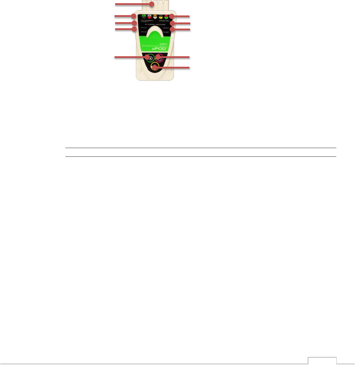
2.1.3.4. 3882 Wireless SpO2 oPOD
The Wireless SpO2 oPOD communicates the pulse waveform, heart rate and perfusion index to
the 3880 monitor. The pulse waveform can be displayed and is output from the 3880 monitor as
a MRI system gating input. The SpO2 oPOD is powered by one battery that is charged when
docked to the 3880 monitor. The wireless oPOD features internal temperature cutoff protection
in the event that the operating temperature exceeds the designed limits. The wireless SpO2
oPOD has the following hardware features.
1. RF Connection
2. RF Channel Indicators, 1 or 5, 2 or 6, 3 or 7, 4 or 8
3. OFF Button
4. RF Channel Selector
5. ON Button
6. Channel 5-8 Indicator – indicates channel indicator count 5 - 8
7. SpO2 Sensor Connector
NOTE
• Turn off PODs when not in use
1
1
6
3 3
2
4
1
2
2
6
2
2
3
4
5
7
5
2-27
2.1.3.5. 3881 Wireless ECG ePOD
The Wireless ECG ePOD communicates two channels of ECG simultaneously to the 3880
monitor. These two channels of ECG can be displayed with lead of Trace A output from the
3880 monitor as a MRI system cardiac gating input. The ECG ePOD is powered by one battery
that is charged when docked to the 3880 monitor. The wireless ePOD features internal
temperature cutoff protection in the event that the operating temperature exceeds the designed
limits. The wireless ECG ePOD has the following hardware features.
1. RF Connection
2. RF Channel Indicators, 1 or 5, 2 or 6, 3 or 7, 4 or 8
3. OFF Button
4. RF Channel Selector
5. ON Button
6. Channel 5-8 Indicator, indicate channel indications count 5 - 8
7. ECG Lead Wire Connector
NOTE.
• Turn off PODs when not in use
7
1
2
2
6
2
2
3
4
5
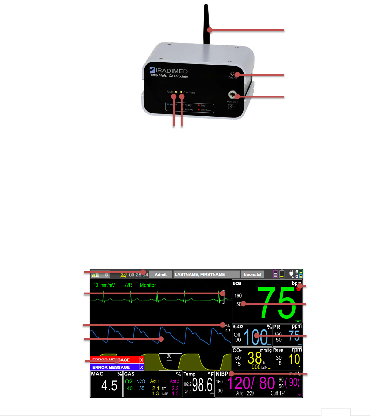
2-28
2.1.3.6. 3886 Wireless Multi-Gas Unit
The 3886 Multi-Gas unit removes the airway tether to the monitor by residing on the anesthesia
machine and wirelessly communicating patient gas information to the 3880 MRI Monitor.
1. Antenna
2. Zero Port
3. Nomoline Sample line Receptacle
4. Wireless Communication LED
5. Power LED
2.1.4. User Interface Overview
2.1.4.1. Displayed Information (3880 and 3885-T Remote Tablet)
High resolution color graphics facilitate waveform analysis and vital sign numeric interpretation.
Important display elements are designed to be legible at a distance of 1 meter. When using the
3880 system always adjust the viewing angle of the display to complement your line of sight
and always ensure that your view remains unobstructed.
3
2
1
4
8
6
9
7
5
1
2
3
5
4
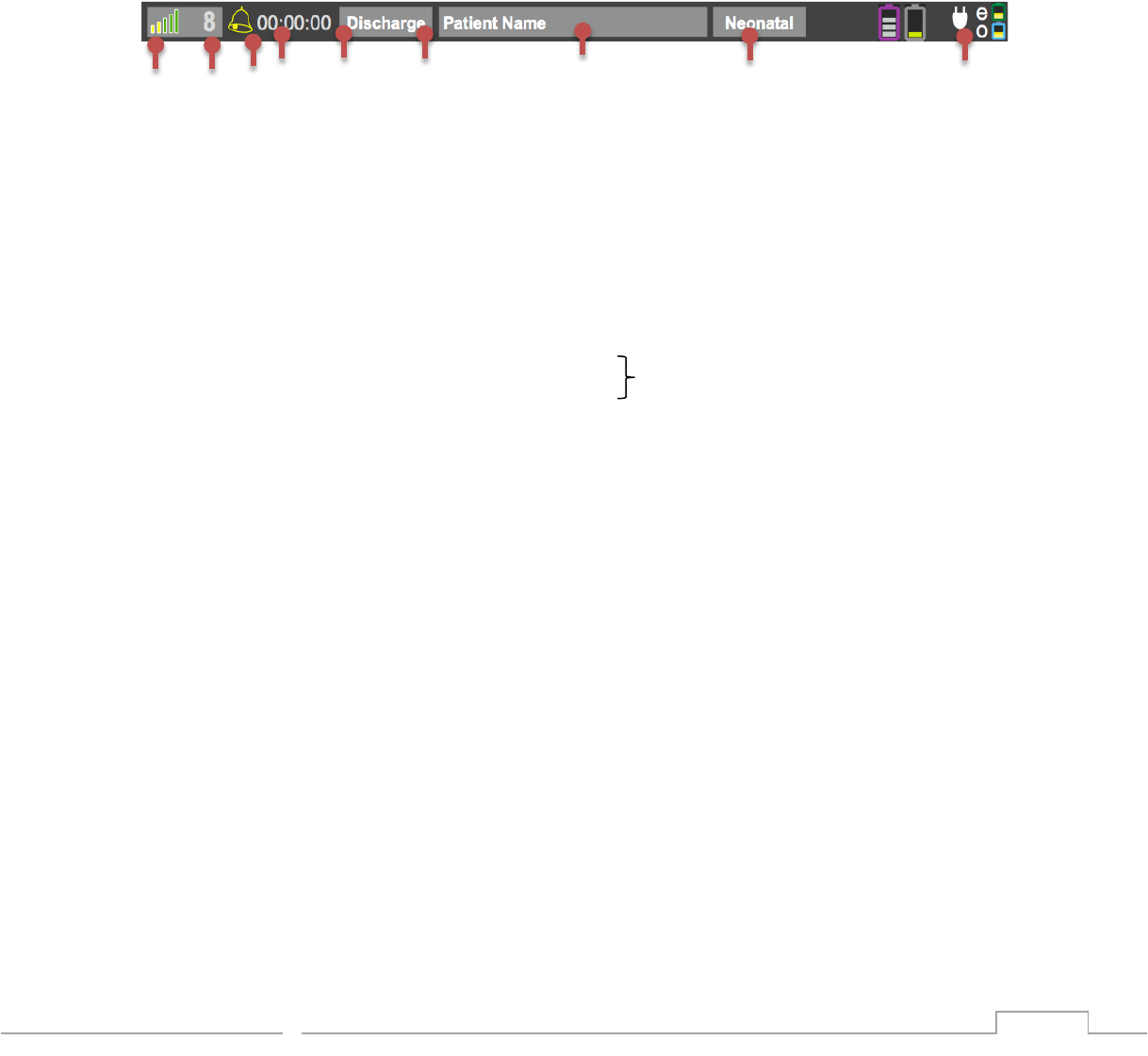
2-29
1. Vital Sign Unit of Measure
2. Alarm Upper and Lower Limits
3. Current Vital Sign Numerical Measurement
4. Vital Sign Description
5. Vital Sign Waveform
6. SpO2 Perfusion Index
7. ECG Indicator
8. Message and Alerts Area
9. Information Bar
2.1.4.1.1 Information Bar
The information bar (located along the top of the screen) provides system, patient and
monitoring information including access to case management, patient type and user setting
functions.
1. Wireless channel signal strength
2. Wireless channel (1-8)
3. Current state of the alarm sound: If alarm sounding, clapper swings and glows red
4. State of Alarm, indicates ALARMS OFF or ALARM Occurring
5. Clock: Current Time
6. Admit / Discharge Button
7. Current Patient Name
8. Patient Type Selection
9. Power Status: Battery, Charge and AC
a. Purple Battery Symbol = 3885-T Remote Tablet
b. Gray Battery Symbol = 3880 Monitor
c. Green = 3881 ECG ePOD display of POD battery icon also indicates
d. Blue = 3882 SpO2 oPOD communication link with POD
e. White AC power connected at 3880 Monitor unit icon
2.1.4.2. Vital Sign Numerics
Vital sign numerical boxes (located in the right and bottom of the screen) are uniquely colored
and labeled framed boxes that display the numeric measurements for each monitored vital sign
parameter. The current alarm limits settings (where applicable), parameter-specific settings and
associated messages may also be displayed within these boxes to alert for potential or detected
problems. In addition, touching the vital sign box allows entry into the menu of the respective
parameters.
1
2
3
5
6
7
8
9
4
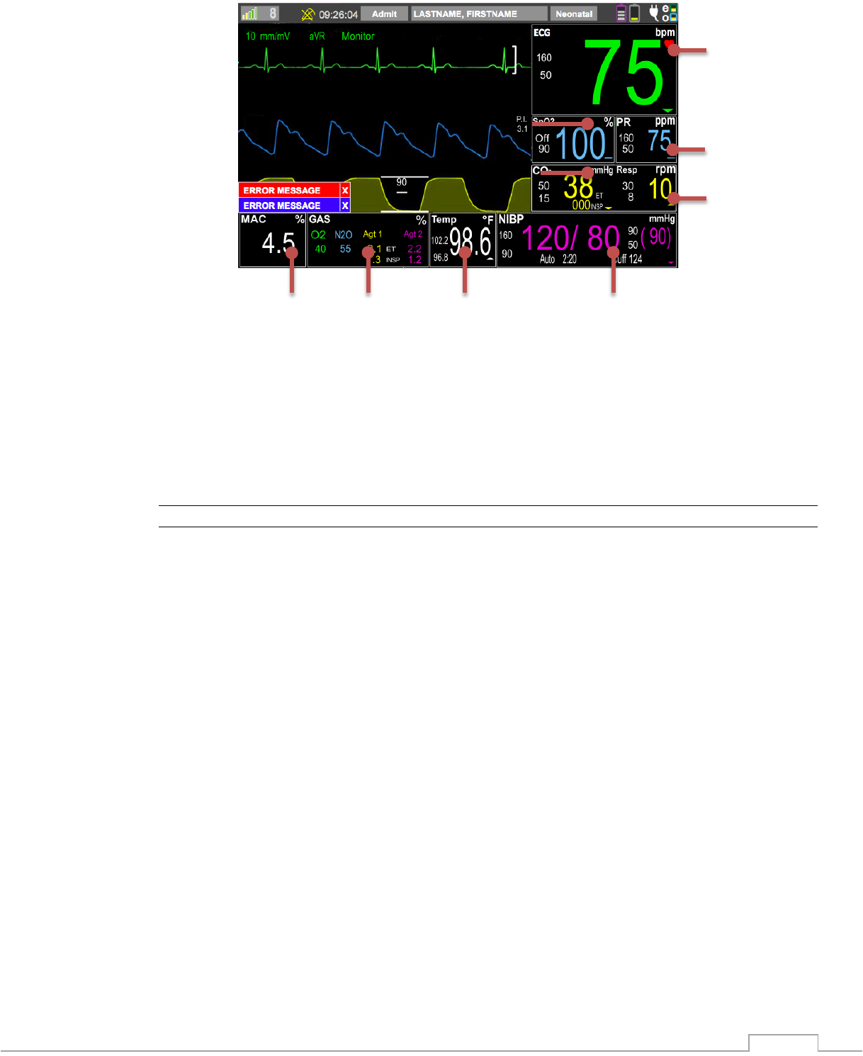
2-30
1. Heart Rate Vital Sign Box – Electrocardiogram heart rate measurement
2. SpO2 Vital Sign Box – Pulse Oximetry / Blood Oxygen Saturation measurement
3. PR Vital Sign Box – Pulse Rate from SpO2
4. CO2 Vital Sign Box – Capnography measurement
5. RESP Vital Sign Box – Respiration Capnography breath rate measurement
6. NIBP Vital Sign Box – Non-Invasive blood pressure measurement
7. Temp Vital Sign Box – Temperature measurement
8. Gas Vital Sign Box – Anesthetic Agent, Oxygen and N2O measurements
9. MAC Vital Sign Box – Minimum Alveolar Concentration
NOTE
• Under certain conditions one or more vital sign numeric may display dashes, which
indicate that no data is available.
• If a parameter is disabled or unavailable, the vital sign boxes will be empty.
1
3
5
8
7
6
2
4
9
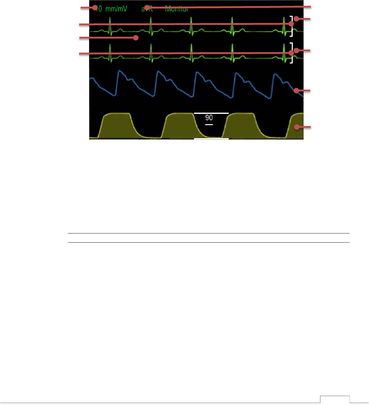
2-31
2.1.4.3. Vital Sign Waveforms
Vital sign waveforms (located in the center of the screen) are uniquely colored waveforms for
the ECG, SpO2 and CO2 parameters. These waveforms are fixed across the screen, adjustable
and updated from left to right with an erase bar. The color of the waveform corresponds to the
associated vital sign box numeric for that parameter.
1. ECG Trace A Lead View
2. ECG Trace A
3. ECG Trace B
4. SpO2 Waveform
5. CO2 Waveform
6. ECG Trace B Scale Indicator
7. ECG Trace B Lead View
8. ECG Trace A Scale Indicator
9. ECG Scale
NOTE
• Under certain conditions one or more vital sign numeric may display dashes, which
indicate that no data is available.
• Up to four waveforms can be displayed, but if a parameter is turned off or unavailable
that waveform portion of the screen will be blank.
1
3
4
5
8
6
7
9
2
P. I.
3.1
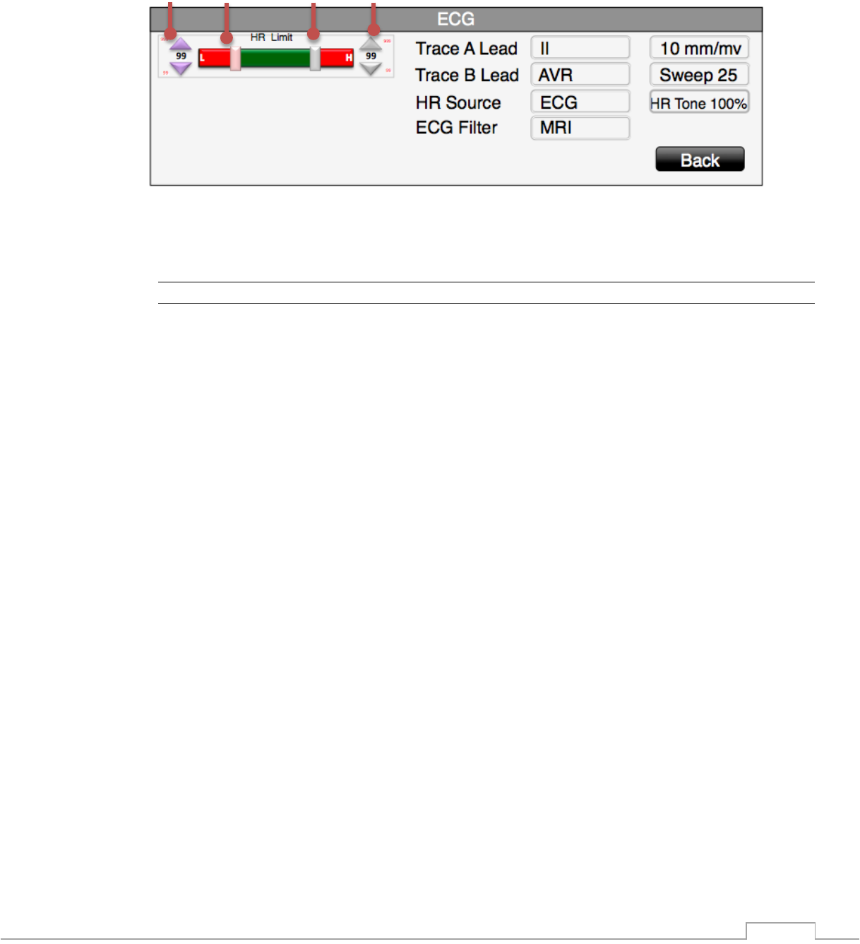
2-32
2.1.4.4. Alarm Example
Alarm adjustments can be made by touching the corresponding vital sign numerical box of the
alarm that needs adjusting.
1. Lower Alarm Limit Fine Adjustment
2. Lower Alarm Limit Quick Slide Adjustment
3. Upper Alarm Limit Quick Slide Adjustment
4. Upper Alarm Limit Fine Adjustment
NOTE
• Green: range of numerical values that are inside the alarm limits and will not trigger an
alarm.
• Red: range of numerical values that are outside the alarm limits and will trigger an
alarm.
4
3
2
1
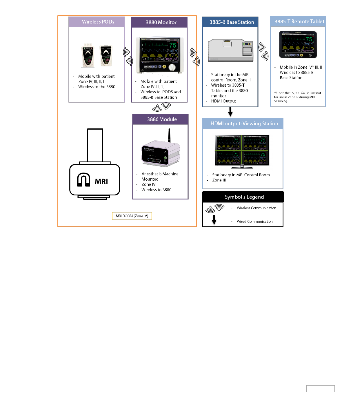
2-33
2.1.5. System Use Model
The diagram below illustrates an example of the 3880 system when used for MRI patient
monitoring.
The 3880 non-magnetic patient monitor (2) is a multi-parameter vital sign monitor positioned
near the patient during the procedure as well as transport. The 3880 acquires the patient vital
sign measurements wirelessly from the ECG and SpO2 PODs (1) as well as traditional
connections for NIBP cuff, CO2, and fiber optic temperature probe.
The patient monitoring experience can be enhanced by utilizing the 3885-B Base Station (3).
The 3885-B Base Station is a data consolidation hub, data router, battery charger and
centralized recorder. The 3885-B Base Station enables remote monitoring in the control room
by wirelessly connecting(repeater) the 3885-T Remote Tablet (4) with the 3880 monitor (2). The
3885-T Remote Tablet is intended to be used as a secondary display control interface for the
3880 monitor (2).
The 3885-B Base Station also enhances patient monitoring abilities by integrating a HDMI
output enabling a remote viewing station utilizing standard Audio Visual components.
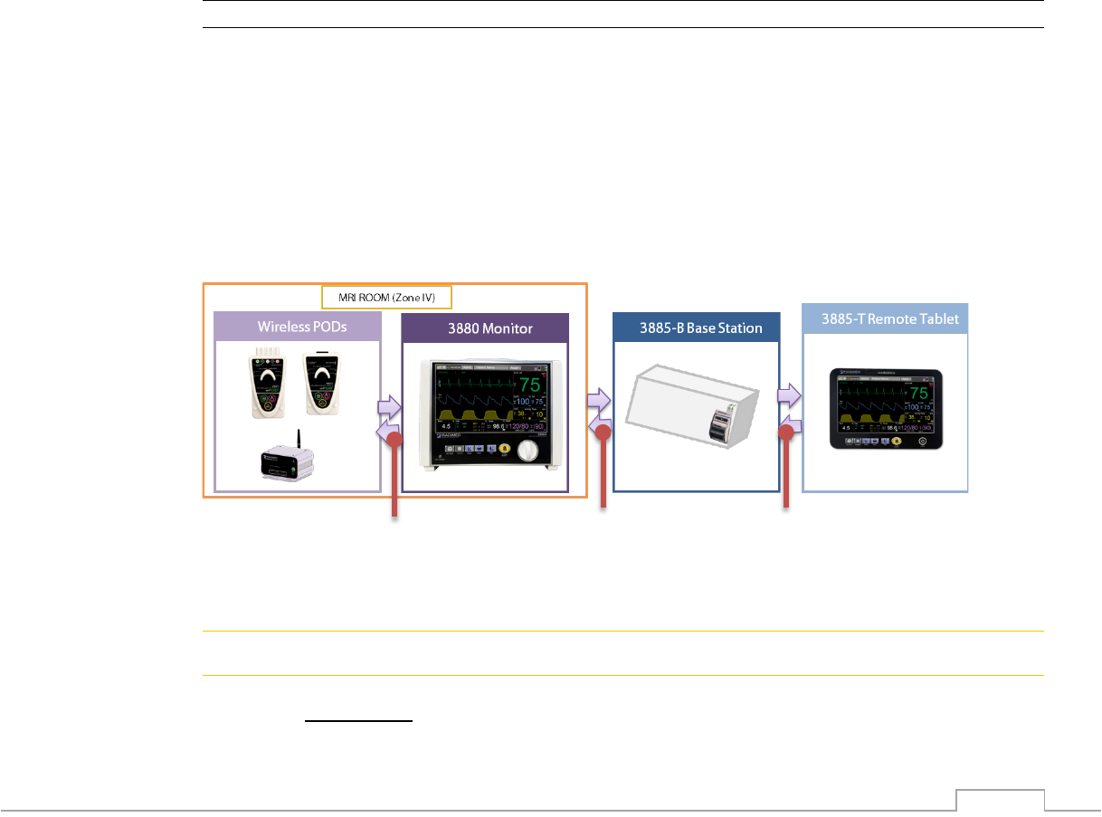
2-34
2.1.6. General Wireless Principles
There are 8 user selectable wireless channels utilized by the 3880 system. Once a user
matches the desired wireless channels of the PODs, 3880 monitor, 3885-B Base Station, and
3885-T Remote Tablet the system will automatically communicate the information utilizing
wireless technologies. The 3880 system utilizes a frequency hopping 2.4 GHz spread spectrum
wireless technology (FHSS) with proprietary hopping durations and patterns.
The 3880 system is designed to work in the 2.4 GHz ISM Band and special frequency options
are selectable to satisfy regulatory requirements for varying countries. This type of wireless
technology has been utilized in MRI patient monitors for over 20 years.
The 3880 system has 8 unpublished and secure dedicated wireless ‘channels’ which optimize
various radio settings to produce the most robust communications possible under very difficult
MR and RF environments. This 3880 non-magnetic monitor overcomes this problem when
communicating with the 3885-B Base Station then to the Remote Tablet by hopping rapidly
throughout the band in a pseudo-random pattern.
In addition to the 3880 system’s ability to communicate with the 3885-B Base Station , the 3880
system features lower powered radios to communicate with the PODs. The Wireless ECG and
SpO2 PODs communicate directly with the 3880 patient monitor with 1 mW RF power which
transmits in the 2.4 GHz band.
NOTE
• The 3885-T Remote Tablet can only operate if the 3880 patient monitor and 3885-B
Base Station are turned on with all components on the same channel. All audible and
visual information displayed on the main monitor is heard and seen on the remote unit
within 1 second. A symbol displays in the upper right-hand corner of the screen to
indicate both devices are connected and active. The 3885-T Remote Tablet has access
to all the same functions as the 3880 except for the Service Menu and Option
Configuration modes.
• The 3880 system is not wirelessly networked to other external systems
An illustration of the wireless technology utilized in the 3880 system is below:
1. FH Spread Spectrum 2.4 GHz Wireless Communication
2. FH Spread Spectrum 2.4 GHz Wireless Communication
3. Low Power 2.4 GHz Wireless Communication
! CAUTION
• 3880 system utilizes 8 independent channels. Always ensure all wireless components
are on the same channel prior to monitoring a patient.
• Avoid having multiple 3880 systems operate on the same wireless channel.
3
2
1
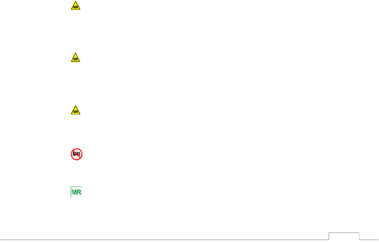
2-35
• Locate the 3885-B Base Station antennas, the 3880 Monitor and 3885-T Remote Tablet
and the PODs more than 1 meter (3 feet) from other sources of RF energy in the 2.4
GHz band. (ie: WiFi Hot Spot)
2.1.7. Wireless Commands
Menu commands that control the patient parameter and strip recorder/printing functions are
communicated between the 3880 non-magnetic monitor and the 3885-T Remote Tablet.
Other operational control settings remain localized to each device and are not communicated.
• Alarm volume
• Pulse volume
• Display Brightness
• Click volume
• Wireless Channel
• Alarm sound on/off
2.1.8. MRI Conditions
All system components of the 3880 system except for the 3885-B Base Station are designed to
be as non-magnetic as possible to help alleviate some of the hazards associated with magnetic
operating environments. Having a non-magnetic design allows clinicians to place the 3880
system in the most efficient and optimal position for the highest possible patient care. Operation
in magnetic fields greater than what is specified for each component may affect its operation
and performance. Below are some of the conditions and general guidelines to follow for safe
MRI operation.
3880 multi-parameter monitor
• Non-Magnetic design is capable of operation up to a 30,000 Gauss (3 Tesla) magnetic
field.
• Use with Ultra-High Field MRI Systems up to 3 Tesla static field.
• Not for use inside a MRI system bore.
ECG and SpO2 PODs
• Non-Magnetic RF shielded design with 30,000 gauss restriction, able to operate in the
MRI system Bore during imaging.
• Use with Ultra-High Field MRI Systems up to 3 Tesla static field.
• Use with whole body average Specific Absorption Rates (SAR) up to 4.0 W/kg or less.
3885-T Remote Tablet
• Non-Magnetic design capable of operation up to a 15,000 Gauss (1.5 Tesla) magnetic
field.
• Not RF shielded for use inside the MRI Exam Room (Zone IV) during imaging.
3885-B Base Station
• Contains Ferrous Materials and is designed to be operated in Zone III.
• Not for use inside the MRI Exam Room (Zone IV)
3880 Patient Worn Accessories
• Non-Magnetic design with unlimited gauss restriction able to operate in the MRI system
bore during imaging.

2-36
3880 Patient Worn ECG Accessories
• Use with Ultra-High Field MRI Systems greater than 0.5 Tesla static field.
• Use with whole body average Specific Absorption Rates (SAR) up to 4.0 W/kg or less.
NOTE
• When moving the 3880 monitor within high magnetic fields (>2,000 gauss) Eddy Current
effects may be noticeable. These are forces generated in the device which resists
motion through the intense magnetic field. Such effects are normal and present no risk
of free magnetic movement of the unit.
• Scanning directly across the plane of the ECG electrode, a slight image distortion may
be seen at the skin surface where the ECG electrode is positioned.
• Accessory cables and tubing shall be placed parallel to each other and aligned with the
main center line of the MRI Bore.
• 3885-T Remote Tablet is non-magnetic to aid in the patient setup workflow. It is capable
of operation up to 15,000 Gauss but is not intended for operation during scanning as
artifacts may be noticeable on the image
! WARNING
• The 1120 AC Adapter is magnetic. Keep outside of the 1,000 Gauss line, or at least 10
feet (3 meter) from the MRI magnet. Secure with Velcro straps provided to the floor.
NEVER Velcro, never secure the AC Adapter directly to the monitor or mobile cart.
• To ensure safety, always position the 1120 AC Adapter in a manner which allows for
easy disconnection of the device from AC mains.
• The 3885-B Base Station contains ferrous material and should not be taken into the MRI
room suite Zone IV.
• Use with higher SAR greatly increases the risk of patient burns.
• The high radio frequency (RF) power used in MRI scanning poses an ever-present risk
of excessive heat at the monitoring sites and, therefore, the risk of RF burn. The risk of
patient burn greatly increases if power levels greater than a whole body averaged
specific absorption rate (SAR) of 4.0 W/Kg is used. Monitoring of the ECG based upon
the whole body average SAR of 4.0 W/Kg may underestimate the actual SAR value at
the ECG leads. When monitoring unconscious patients additional precautions maybe
required.
• RF burn risk increases when metallic items and / or multiple conductive sensors/cables
are in use such as ECG lead wires. Such combinations are not recommended. Always
remove non IRadimed accessories prior to performing a MRI procedure.
• Patient lead cables which become inadvertently looped during an MRI examination may
act as conductive lines for RF induced currents, resulting in excessive heating and
possible burns. When patient lead cables or other cables form a conductive loop in
contact with the patient's tissue, minor to severe burning can result.
• Position all cables in the center of the MRI bore and avoid contacting the internal side of
the MRI bore during scanning.
! CAUTION
• High levels of RF energy may cause patient heating or burns. Inspect electrode sites for
heating for scan times (i.e., per pulse sequence) greater than 15 minutes.
• Medical drug treatment can alter the sensitivity to skin heating.
• When using or repairing the equipment, do not bring any tools or components containing
ferrous material into the magnet room (Zone IV). Risk of serious injury and/or damage to
the equipment can result.
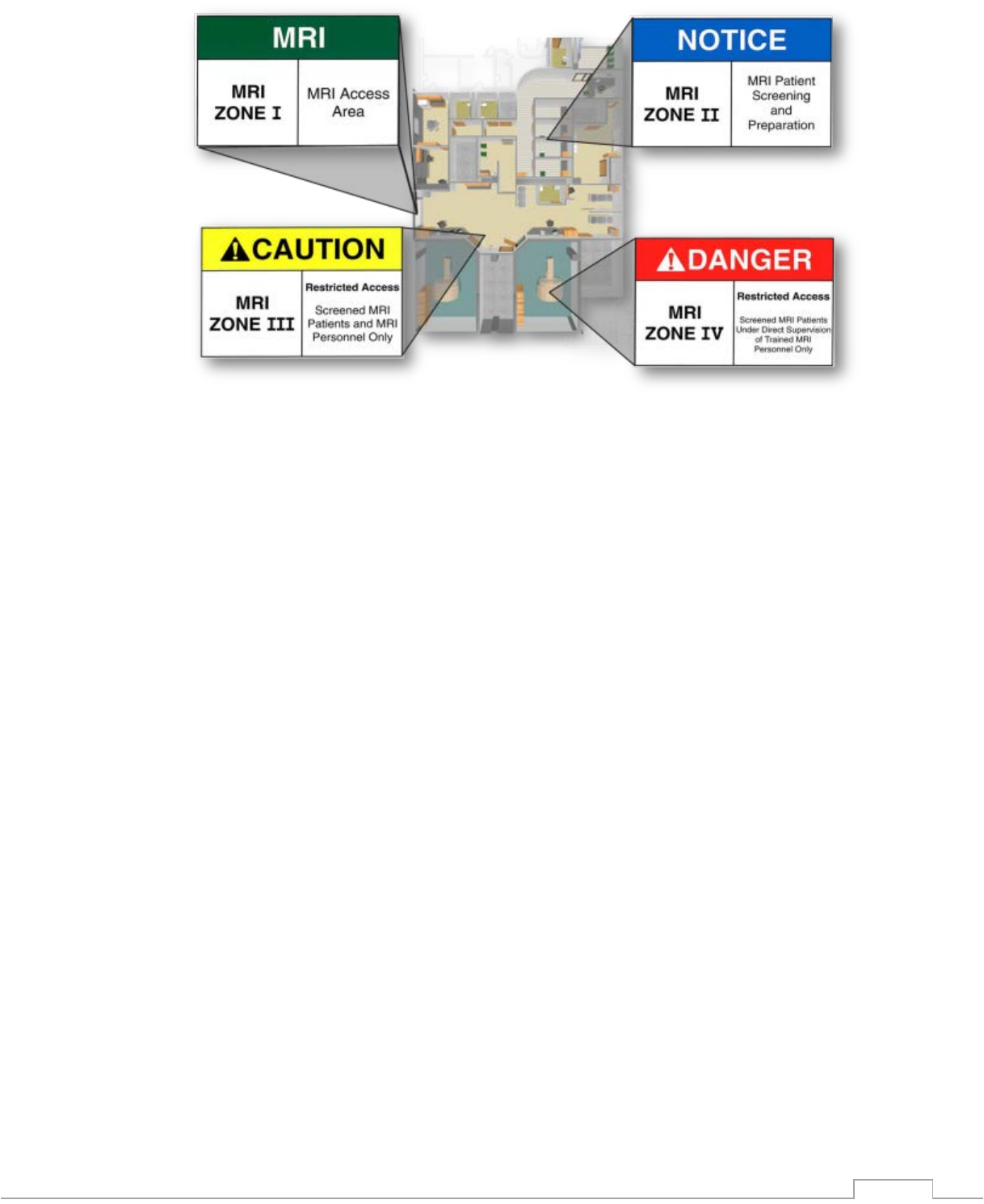
2-37
Typical MRI Facility Zones
2.1.9. Cleaning
For cleaning guidelines review the Care and Cleaning section 8.4 of this manual.
2.1.10. Repair
The 3880 System or any of its parts should be repaired in accordance with written instructions
provided by the IRadimed. The user has the sole responsibility for any malfunction which results
from improper use, faulty maintenance, improper repair, damage or alteration by anyone other
than IRadimed-authorized service personnel.
For repair guidelines review Section 8 Pre-Use Operator Verification, Troubleshooting and User
Maintenance of this manual.

2-38
2.2. Initial Setup
2.2.1. Safety Precautions
! WARNING
• The monitor and its components should not be used adjacent to or stacked with non
IRadimed equipment. If adjacent or stacked use is necessary, the monitor and its
components should be observed to verify normal operation in the configuration prior to
use. Never install the monitor directly above the patient.
• To avoid risk of electric shock, this equipment must only be connected to properly
grounded AC outlets with the power cord supplied by IRadimed.
! CAUTION
• If the monitor is going to be in storage and not used for more than 30 days, the battery
pack should be removed from the devices if possible and charged to 50%.
• If the PODs are going into storage for more than 30 days they should be stored 50%
charged and recharged at a minimum of 6 month intervals.
2.2.2. Unpacking the System
1. Confirm that the packing box is undamaged. If the box is damaged, contact the shipper.
2. Open the top of the box and carefully unpack all components.
3. Confirm that all components are undamaged. If any of the components are damaged,
contact the shipper.
4. Confirm that all components are included. If any of the components are missing, contact
your IRadimed representative.
a. Standard Equipment:
• 3880 Monitor
• ECG and SpO2 PODs
• 1120 Power Supply and Cables(P/N 1121, 1122)
• Operators & Service Manual
• ECG, SpO2 and NIBP accessories
b. Optional Equipment:
• 3885-T Remote Tablet and 3885-B Base Station
• Hi-Gain Antenna
• CO2, Gas, Fiber Optic Temperature, and Recorder accessories
• Gating Cable
• Mounting Hardware and Stand
! CAUTION
• Never unpack or assemble items inside the MRI room suite (Zone IV).

2-39
2.2.3. Visual Inspection
Perform the following visual inspection to the installed monitoring system:
• Carefully inspect the patient monitor components for any damage.
• Verify that the patient monitor is properly mounted with specified mounting solutions.
• Verify that the cables between the patient monitor and the connected peripheral devices
are intact and properly connected to the right connectors.
• Verify that the battery is intact and locked into the monitor.
The cleaning precautions, cleaning requirements, cleaning procedures, and recommended
cleaning solutions for the monitor are described in Care and Cleaning section 8.4. For details
about cleaning and disinfecting the accessories, see the instructions for use in the accessory
package.
2.2.4. Functional Inspection
Start-up
Turn on the components of the 3880 system (3880 Patient Monitor, 3885-T Remote Tablet and
wireless PODs).
Verify that the system components start up normally:
• The red, yellow and blue Tri-Color Alarm Dome Light on the 3880 Monitor and 3885-T
Remote Tablet are lit momentarily.
• The speaker on the 3880 monitor and 3885-T Remote Tablet gives an audible beep.
• Check that the normal monitoring screen appears and that all text is readable and clear.
• Check wireless communication.
• Check that there are no error messages on either screen.
NOTE
• Before placing the patient monitor system into use for the first time, the battery should
be fully charged. Keep the monitor system connected to the charger until the battery is
fully charged.
• If multiple systems are ordered perform the start-up procedure on one device at a time.
2.2.5. Mounting
Mounting of monitor components to the roll stand (IV Pole) is described in the instruction sheet
of the stand.
2.2.6. Choosing a location
Consider the following aspects:
• Lighting
• Patient and staff location during procedure
• MRI room visibility
• Space
• Electromagnetic and radio frequency interference
• Traffic flow
NOTE
• Careful consideration should be given when placing the 3880 system components near
other equipment with wireless communication or near high traffic areas. Human traffic
between the systems wireless components can reduce wireless signal power and lead
to reduced quality of wireless service.

2-40
2.2.7. System Power
2.2.7.1. Battery Operation
The 3880 system utilizes Lithium Polymer ‘smart’ battery technology with self-monitoring. When
all components of the system are turned on and communicating, the battery charge status is
displayed on the 3880 Monitor and 3885-T Remote Tablet displays. The actual battery capacity
will decrease over time and a full battery symbol may not indicate the same capacity and
operating time as compared to a new battery.
The system’s batteries each contain lithium-polymer cells and integral safety circuits. As these
cells age, they can expand due to internal gas release, which is anticipated for this type of cell.
However, if excessive expansion occurs, this can result in the battery case expanding
(swelling), and possibly cause failure of the battery case, cells, or safety circuit. If this is
observed, remove the Battery Pack or PODs from use and replace it as soon as possible.
! WARNING
• Avoid damage to the Battery Pack by impact, dropping, overheating, or mechanical
abuse. Never compress, drop, shock, or strike the Battery Pack. Never use objects that
could puncture the internal battery cells. Any of these actions can cause the battery cells
to heat, smoke, or cause catastrophic battery failure, which could result in fire.
• Do not attempt to disassemble the Battery Pack. Damage caused by disassembly or
tool use can result in catastrophic battery failure, which could result in fire.
• Under no circumstances should Battery Packs or the internal cells be incinerated as this
can cause an explosion.
• If PODs or batteries are dropped, perform a physical and functional inspection before
returning them to clinical use.
! CAUTION
• The battery packs may contain slight magnetic properties. Use caution when removing
or inserting the batteries near strong magnetic fields (30,000 Gauss).
• If the 1133 Battery Pack case begins to expand and/or swell, discontinue battery
charging and use immediately, and replace the battery pack. Continued charging will
cause further battery pack case expansion, with possible battery case fracture, and
potential electrolyte leakage.
• Only operate the monitor with the battery pack installed.
• Immediately charge a device that has a low battery.
NOTE
• The operating time depends on the configuration and operation of the 3880 system. For
example, measuring NIBP more frequently will shorten the operating time.
• Review the Battery Maintenance in Section 8 of this manual prior to initial use.
• The 3880 monitor utilizes a user replaceable battery pack which enables continuous
monitoring. The Wireless PODs and 3885-T Remote Tablet feature integrated batteries
so backup devices maybe necessary for continuous monitoring longer than 10 hours.
• If the system is power cycled during a case always confirm settings and patient name
prior to resuming monitoring activities.
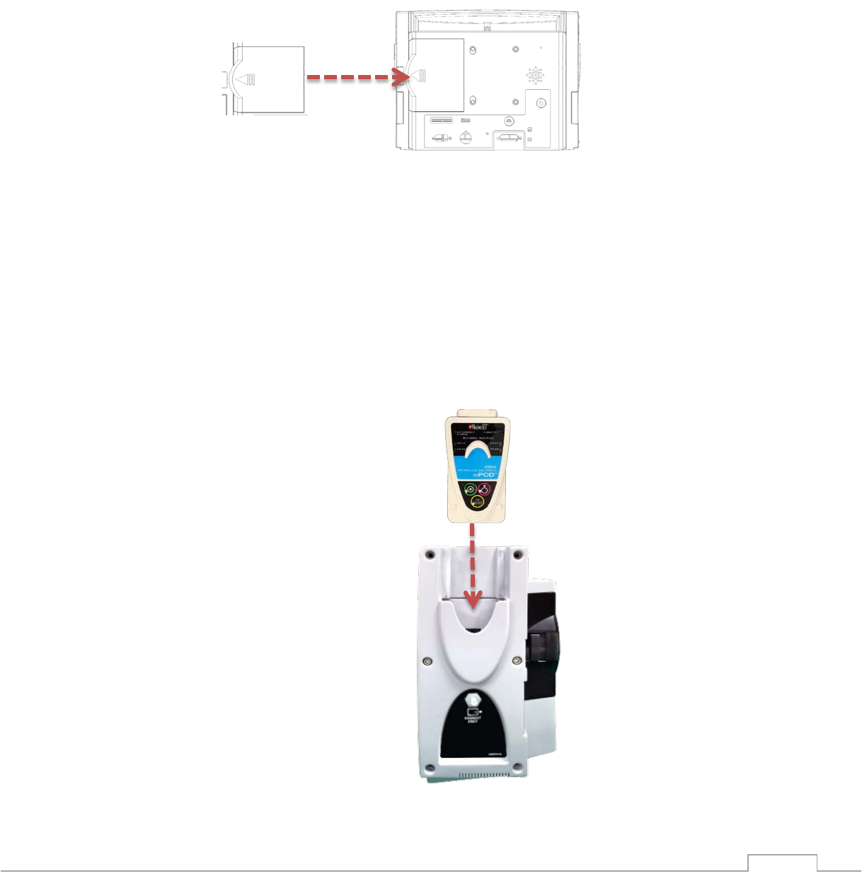
2-41
3880 multi-parameter monitor
The 3880 system has a user replaceable battery located on the rear of the device.
1. Insert the user replaceable battery pack into the battery bay on the rear of the 3880
monitor as shown. The battery pack will lock into place if inserted properly.
2. Connect the system to AC power. Reference the Charging Instructions section 2.2.7.2 in
this manual for additional details.
3. Verify that a green or yellow LED is present on front panel indicating mains power
(Green) and charging (Yellow).
4. Allow to charge for a minimum of 5 hours prior to initial use.
3881 ECG and 3882 SpO2 PODs
The 3880 PODs have an integrated battery that is not user serviceable. Additional PODs
maybe added to this system to allow for continuous operation on battery. The 3880 Non-
Magnetic patient monitor has the ability to charge 2 PODs simultaneously.
1. Disconnect the Patient and insert the PODs with the labels facing outward into the
charging bays located on either side of the 3880 monitor.
2. Connect the system to AC power. Reference the Charging Instructions section 2.2.7.2.1
in this manual for additional details.
3. Verify associated charge indicator LEDs on rear panel.
4. Allow to charge for a minimum of 4 hours prior to initial use.
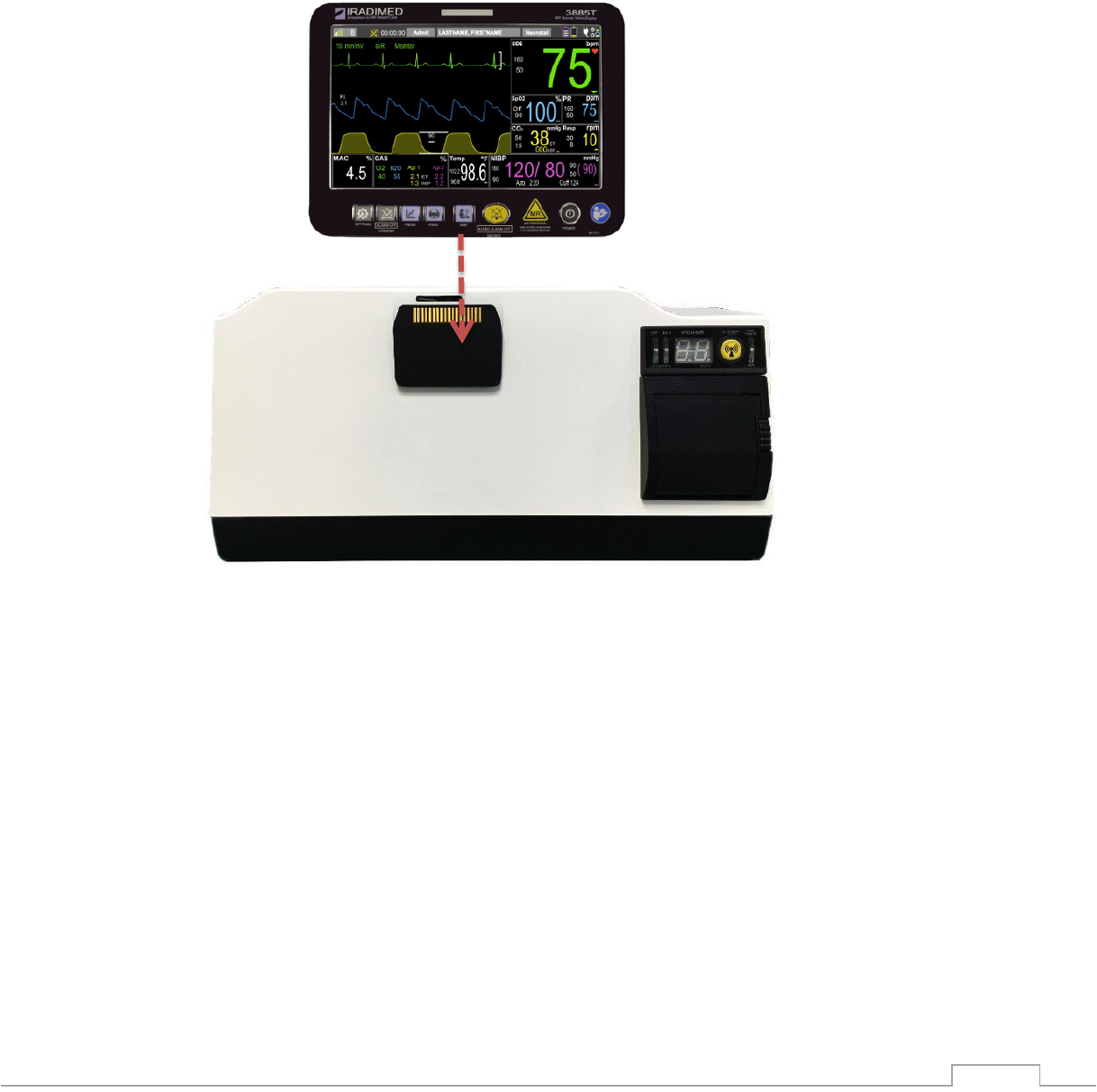
2-42
3885-T Remote Tablet and 3885-B Base Station
The 3885-T Remote Tablet has an integrated battery that is user serviceable. The Remote
Tablet is charged by docking it to a 3885-B Base Station that is connected to AC power.
1. Connect the 3885-B Base Station to AC power. Reference the Charging Instructions
section 2.2.7.2 in this manual for additional details.
2. Lower the 3885-T Remote Tablet onto the 3885-B Base Station Charging Dock.
3. Verify that a green or yellow light is present on the right most 3885-B Base Station LED.
4. Allow to charge for a minimum of 5 hours prior to initial use.
3885-B Base Unit, Charger and Wireless Repeater Link for 3885-T Remote Tablet
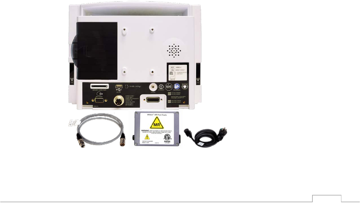
2-43
2.2.7.2. Charging Instructions
2.2.7.2.1. Connecting and Disconnecting AC Power
Always connect the 1120 AC power supply to a properly grounded 3-wire power receptacle. If
the quality of the earth grounding is in question, use battery power for the monitoring system.
Avoid the use of extension cords. The 3880 Monitor and 3885-T Remote Tablet will
automatically switch to battery power when disconnected from AC Power. Always check the
battery charge level prior to disconnecting AC power to ensure there is sufficient battery power
for the procedure. If disconnected from AC power without a battery installed or a dead battery
installed, the 3880 Monitor will revert to factory default settings.
To connect the power supply, follow these steps:
3880 Monitor
1. Locate
• 3880 Power Input (1)
• 1122 - 3M (~10 ft) Shielded DC Cable (2)
2. 1120 MRI Power Supply (3)
3. Country Specific Power Cord (4)
4. Screw the male end of the 1122 Shielded Cable (2) directly into the 1120 MRI Power
Supply (3)
5. Attach the Country Specific Power Cord (4) to the MRI Power Supply (3)
6. Position the 1120 MRI Power Supply (3) outside the 1,000 Gauss line, or 10 feet (3
meters) from the MRI system when placed inside the MRI exam suite Zone IV.
7. Place the Country Specific Power Cord (4) into the designated AC power outlet.
8. Screw the female end of the 1122 Shielded Cable (2) directly into the power input
receptacle (1) on the rear of the 3880 Monitor
9. Check for a green /yellow power/charging indicator LED light on the front of the 3880
Monitor
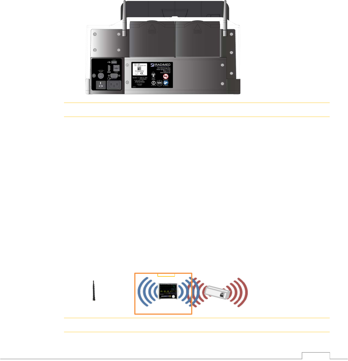
2-44
3885-B Base Station, Optional
1. Locate the power cord (P/N 1128 in US) and ensure the Base Station power switch is in
the OFF position. (1)
2. Locate a suitable location in the control room that enables access and wireless
communication. See 2.2.8 for antenna connection.
3. Attach the power cord to the 3885-B Base Station (2)
4. Place the power cord into the designated AC power outlet.
5. Turn the 3885-B Base Station power switch to the ON position (1)
6. Check for green LED light on the front of the 3885-B Base Station.
! WARNING
• The 1120 power supply contains magnetic properties. Keep outside the 1,000 Gauss
line, or 10 feet (3 meters) from the MRI system.
• Never Velcro or attach the power supply directly to the monitor, monitor mounting
solution, or IV pole.
• The 3885-B Base Station contains ferrous materials that are attracted to magnetic fields.
DO NOT install or place the 3885-B Base Station or its components in the MRI room
(Zone IV).
2.2.8. Antenna Strategies
The 3880 system uses 2.4 GHz bidirectional communication to communicate between the 3880
monitor and the 3885-T Remote Tablet. There are different antenna options to support various
environments and workflow scenarios. Please contact your IRadimed representative for
information regarding one of the optional antenna options.
2.2.8.1. Omni Directional Antenna
The Omni Directional Antenna is the standard antenna that is included with the 3880 Monitor
and 3885-B Base Station. This bidirectional broadcast antenna is the easiest to use and
provides patient workflow flexibility in typical MRI environments.
! CAUTION
• Locate the 3885-B Base antennas, the 3880 and 3885-T and the PODs more than 1
MRI Room
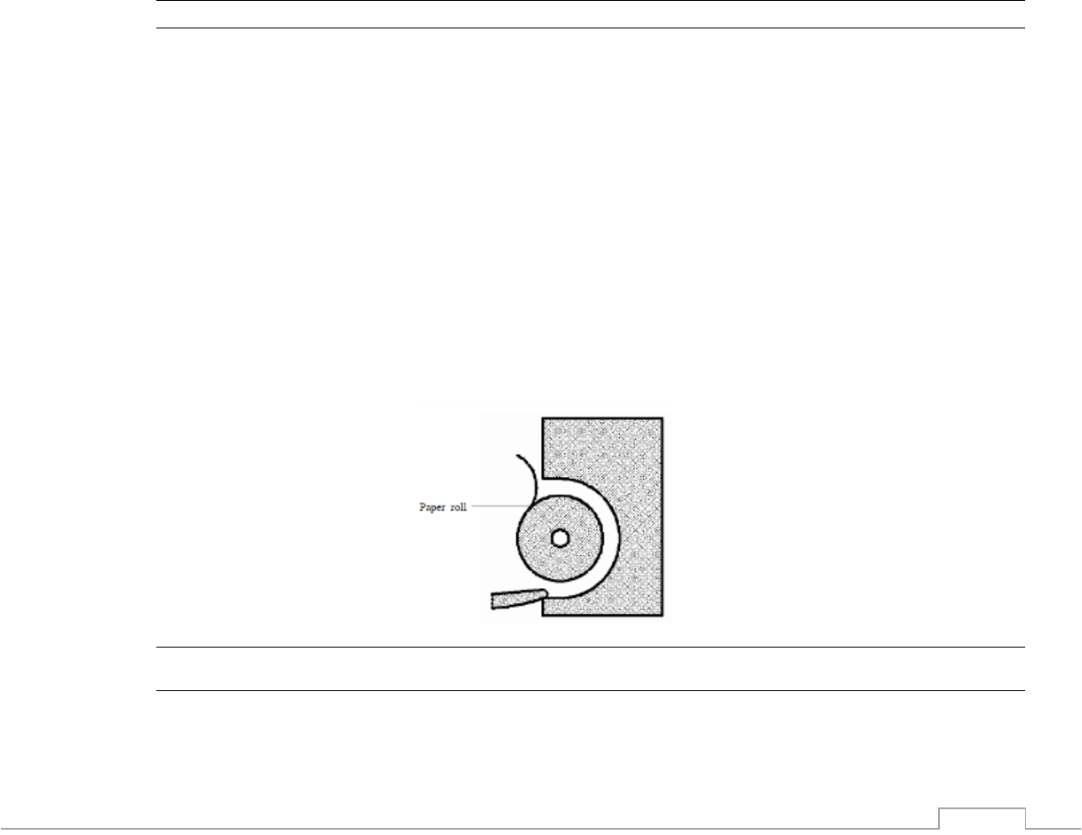
2-45
meter (3 feet) from other sources of RF energy in the 2.4 GHZ band. (ie: WiFi Hot Spot).
2.2.8.3.1 LED Power Indicator
The power indicators located on the 3880 Monitor and optional 3885-B Base Station are two
color LEDs and the PODs are a single color LED that provides a visual indication of the power
status as indicated below. Reference the System Hardware Components (accessories not
shown) section 2.1.2 of the operation manual for specific LED locations.
3880 Monitor and 3885-BBase Station:
• Solid Green: A solid green light indicates that the device is connected to AC power and
the batteries are fully charged.
• Solid Yellow: A solid yellow light indicates that the device is connected to AC power
and the batteries are being charged.
• No Light: A blank LED light indicates that the device is disconnected from AC power.
Wireless PODS:
• Solid Green: A solid green light indicates that the device is powered ON.
• No Light: A blank LED light indicates that the device is powered OFF.
NOTE
• No Light: indicates that the device is not connected to AC power and the system will need to
be powered on to check the battery charge status on the display.
• Charge status of each communicated component is visible on the 3880 system’s displays.
2.2.9. Loading Recorder Paper
When equipped with the optional Strip Chart Recorder, the 3885-B Base Station is capable of
providing hard copies of up to two waveforms and/or trend information. To load paper into the
recorder, follow the following procedure:
1. Press the release button to open the door on the recorder
2. Insert a new roll of paper into the compartment so the paper end is on the bottom
3. Pull approximately 2 inches (50 mm) of paper from the roll then extend it over the top of
the door
4. Close the recorder door
5. Tear off the paper to complete the loading
6. Confirm that the paper is loaded correctly by printing a sample
! CAUTION
• Use only specified thermal paper. Otherwise, it may cause damage to the recorder’s print
head, the recorder may be unable to print, or poor print quality may result.
• Never pull the recorder paper with force when a recording is in process. Otherwise, it may
cause damage to the recorder.

2-46
• Do not leave the recorder door open.
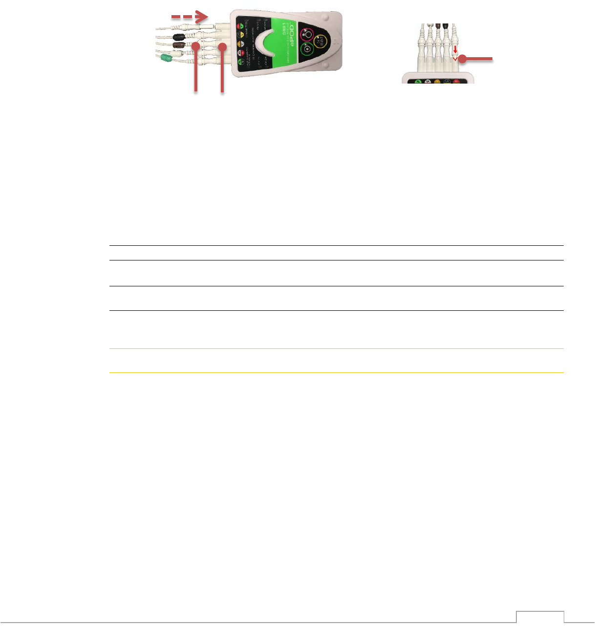
2-47
2.2.10. Connecting Patient Accessories
2.2.10.1. 1811 ECG Wires and 3881 ePOD
The wireless ECG POD “3881 ePOD” and lead wires are constructed of special material to
reduce the amount of radio frequency (RF) energy that can flow through the components. The
ECG ePOD and lead wires are designed for use in the MRI system bore but should remain
outside of the MRI procedure Field of View (FOV) where possible.
To connect the ECG Lead wires to the ECG ePOD:
1. Locate the 1811 ECG Lead wires (1) and the 3881 ECG ePOD (2)
2. Position the ECG Lead wires with the ECG ePOD so the colors and letters align
3. Firmly insert the ECG Lead wires into the corresponding ECG ePOD receptacle
NOTE: Align the molded arrow on the lead wire with the top side chevron “V” molded in
to the receptacle. (3)
4. Ensure that ECG Lead wires are secure into the ECG ePOD and not loose
5. Verify operation of the MRI cable by connecting it to an ECG simulator or test subject if
one is not available
NOTE
• The ECG Leads are intended specifically for MRI use.
! CAUTION
• Use only ECG Lead wires specifically designed and approved for use with the IRadimed
ECG ePOD. Refer to section 9 for a complete list of available accessories.
! WARNING
• Avoid contact with the MR system bore as this may cause heating of the lead wires or
the patient electrodes.
1
2
3
3
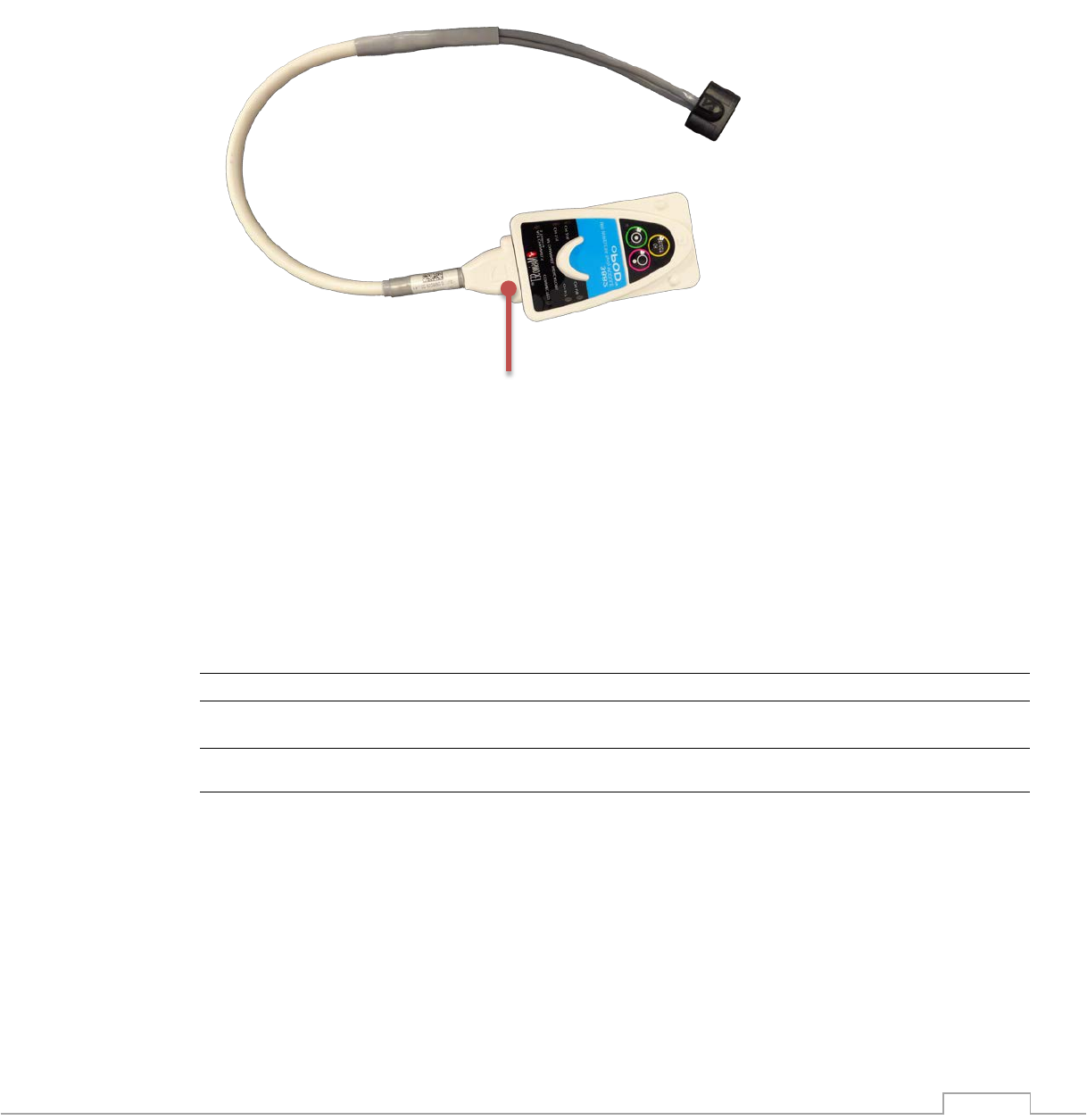
2-48
2.2.10.2. SpO2 1821 Cable and 3882 oPOD
The wireless SpO2 POD “3882 oPOD” and accessories are constructed of special material to
reduce the amount of radio frequency (RF) energy that can flow through the components. The
SpO2 oPODs and accessories are designed for use in the MRI system bore but should remain
outside of the MRI procedure field of view (FOV), where possible.
The SpO2 Sensor cable, P/N 1821 is fiber optic (glass), and mated to the SpO2 oPOD
1. The 1821 SpO2 sensor (1) is mechanically attached to the 3882 SpO2 oPOD.
2. Assure that the SpO2 sensor is firmly connected to the SpO2 oPOD
3. Replacing the sensor requires removal to two screws which are non-magnetic, insert the
replacement SpO2 sensor into the corresponding SpO2 oPOD receptacle and re-apply
the non-magnetic screws. See Service manual for details.
4. Ensure that SpO2 sensor is secure into the SpO2 oPOD and not loose
5. Verify sensor operation by connecting it to a SpO2 simulator or test subject if one is not
available
NOTE
• The SpO2 sensor is a fiber optic assembly intended specifically for MRI use.
! CAUTION
• Use only SpO2 accessories specifically designed and authorized for use with the
IRadimed SpO2 oPOD. Refer to section 9.1 for a complete list of available accessories.
• The SpO2 sensors are constructed of fiber-optic glass and must always be handled with
care to prevent damage. Improper handling can result in inaccurate readings.
• Use only SpO2 sensors specifically designed for use with the SpO2 oPOD (part number
1821)
• Do not use magnetic tools inside of zone IV
1
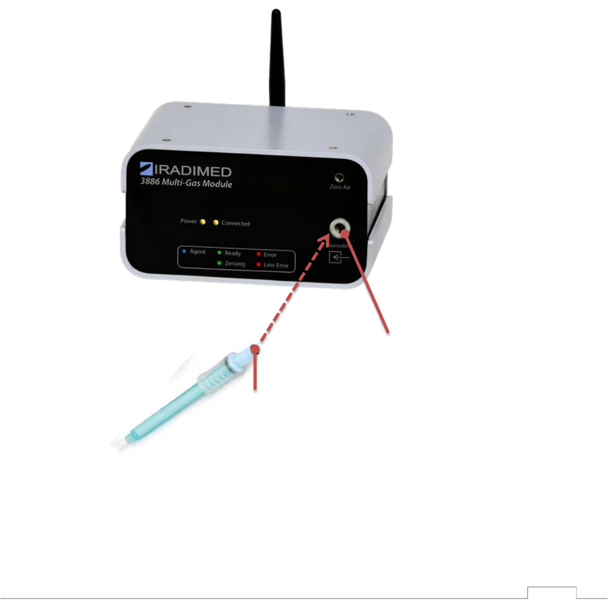
2-49
2.2.10.3. 3886 Multi-Gas / Agent Sampling Lines
The optional CO2/ Multi-gas Anesthetic Agent unit (P/N3886) provides sidestream
measurement of End-Tidal CO2, anesthetic agents, fast O2, respiration with a continuous real-
time CO2 waveform display. This Multi-gas option will also identify and display any two of five
anesthetic agent concentrations. This feature will perform automatic zeroing at periodic
intervals or upon user demand.
To connect the sampling circuit:
1. Attach the country specific AC power cord to the Mains inlet on the rear of the 3886
Multi-Gas unit and switch on the Mains power switch located next to the inlet. The
Green power indicator will light.
2. Locate the sampling line (1) and the CO2 receptacle on the Multi-gas unit (2)
3. Position the sampling line with the light emitting Gas inlet receptacle (LEGI) so they
1
2