Iton Technology MW1601-5P Wi-Fi MODULE User Manual 15 MW1601 5P UserMan P2
Iton Technology Corp. Wi-Fi MODULE 15 MW1601 5P UserMan P2
Contents
- 1. 15_MW1601-5P UserMan_P1.pdf
- 2. 15_MW1601-5P UserMan_P2.pdf
15_MW1601-5P UserMan_P2.pdf
Our Focus , Your Legend 802.11 b/g/n single chip
Iton Technology Corp www.sziton.com
8
Storage Temperature -40℃~125℃
Antenna external
Operation System windows XP32/64,Vista 32/64, Win7 32/64, Linux, Mac
Operation Voltage 3.3V DC
6. Size Of Module Graph
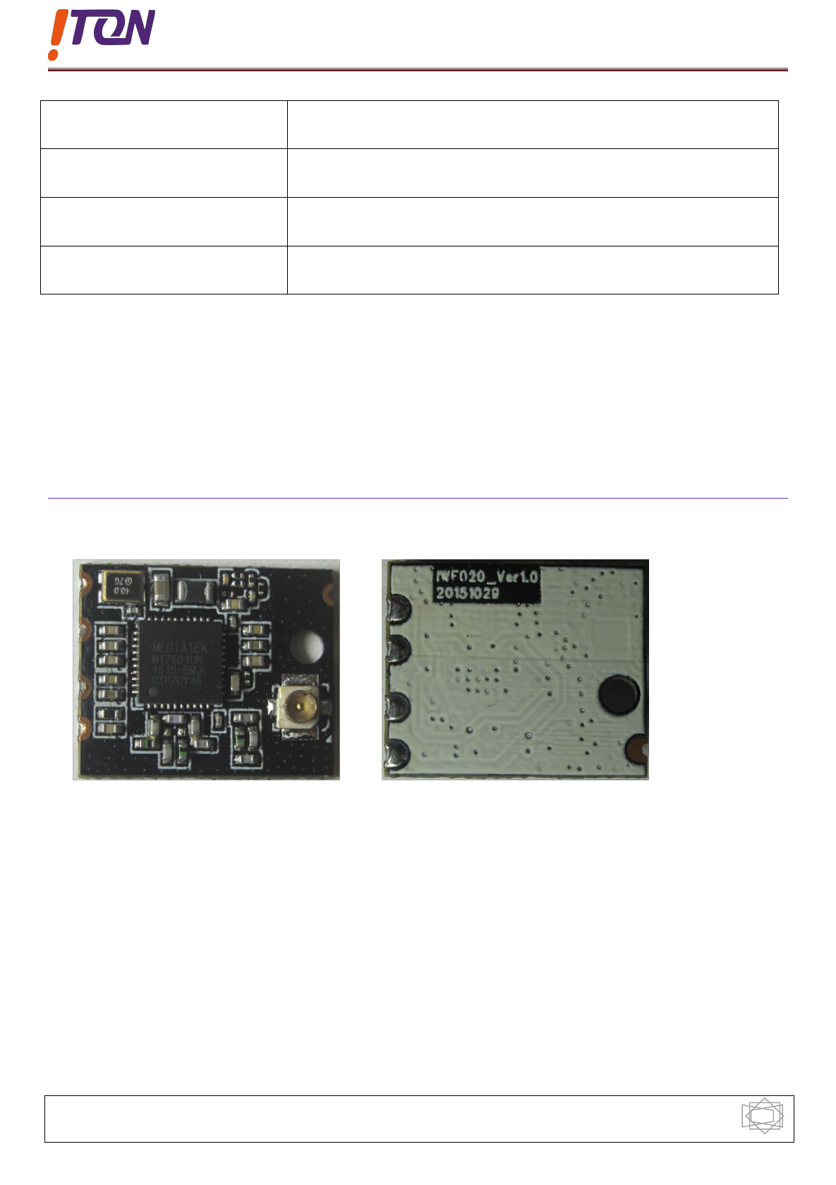
6.1 Physical Map
Our Focus , Your Legend 802.11 b/g/n single chip
Iton Technology Corp www.sziton.com
9
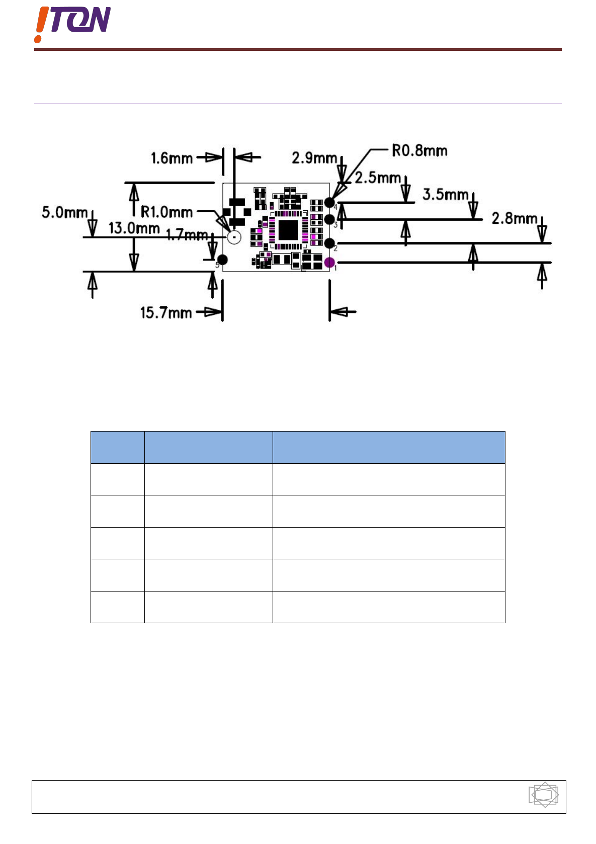
6.2 Machine Size Map And Pin Definition
Pin Definition
Pin Name Description
1 VCC 3.3V
2 DP USB D+ signal
3 DM USB D- signal
4 GND Ground
5 NC No connect
7.Process Parameters
TBD
Our Focus , Your Legend 802.11 b/g/n single chip
Iton Technology Corp www.sziton.com
10
8.Packaging Information
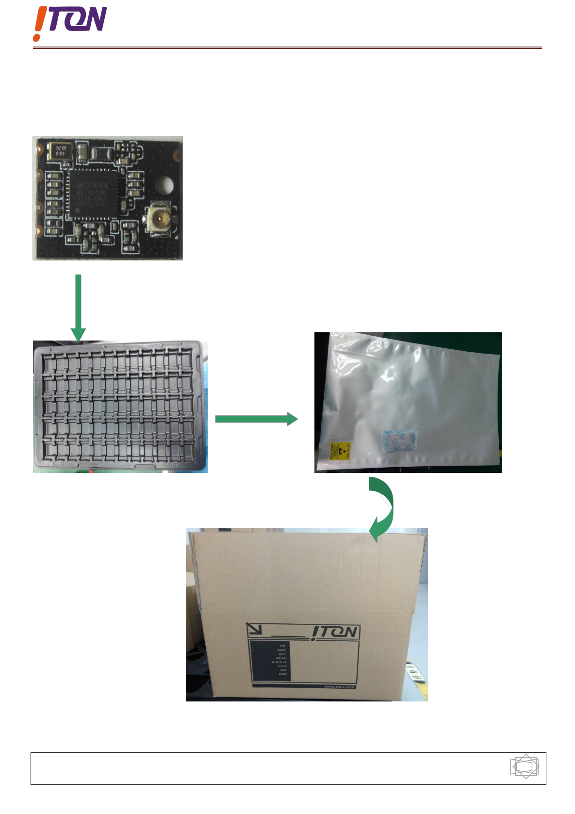
Packing information :blister + vacuum bag
The module into the blister case
Blister (5*10) Vacuum bag
Cartons
The blister packed
module and desiccant
into the vacuum bag
A good vacuum sealed
vacuum bag in turn into
cartons
InstallationGuide
FinishedAssembly
MasterPCB(examples)
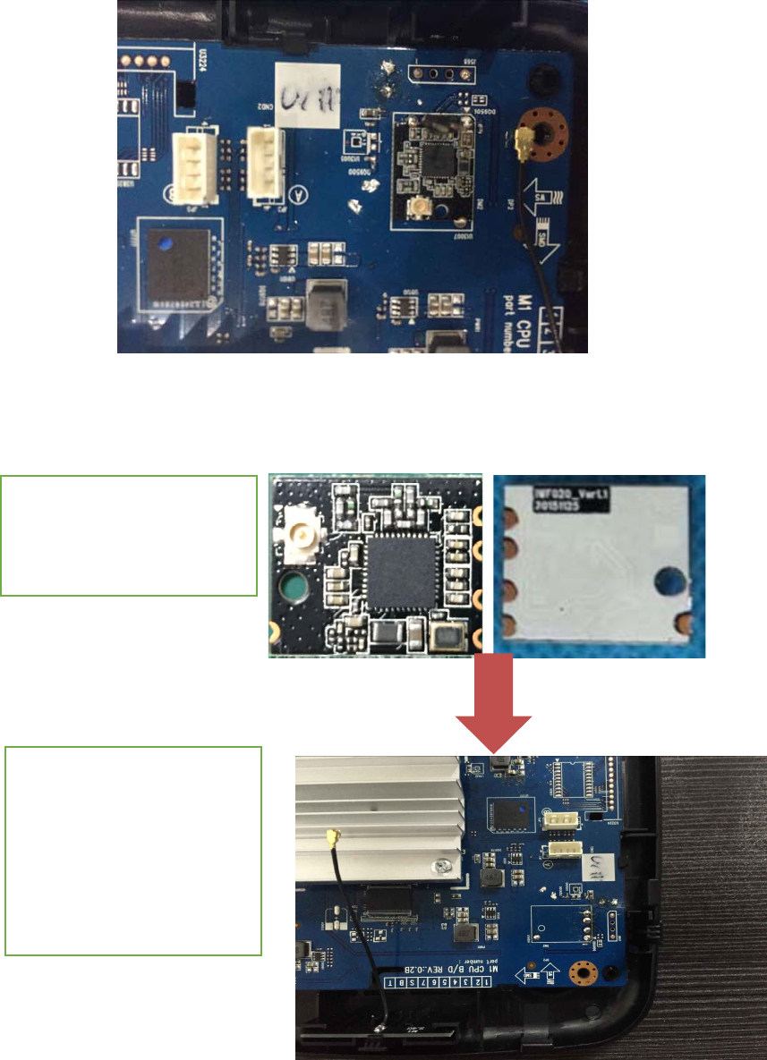
2. Ready the Master PCB
which will connect with
MW1601-5P Module. Check
connection pads is clean
forsoldering.Place the
Module on the Master PCB
with SMT.
1.CheckMW1601‐5PModule
connectionpiniscleanfor
soldering.
9.Application
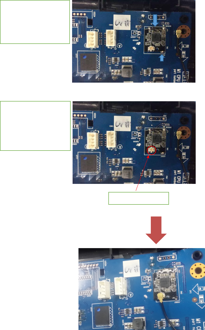
4. Connect DC Power 3.3V
on VCC and GND on Master
PCB.Connect to Antenna by
antenna connector.
Antennaconnector
3. After soldering,Check
all pads are well
connected.
NOTE:The antenna gain should no more than 0 dBi.

NOTE: This equipment has been tested and found to comply with the limits for a Class B digital
device, pursuant to part 15 of the FCC Rules. These limits are designed to provide reasonable protection
against harmful interference in a residential installation. This equipment generates, uses and can radiate
radio frequency energy and, if not installed and used in accordance with the instructions, may cause
harmful interference to radio communications. However, there is no guarantee that interference will not
occur in a particular installation. If this equipment does cause harmful interference to radio or television
reception, which can be determined by turning the equipment off and on, the user is encouraged to try to
correct the interference by one or more of the following measures:
—Reorient or relocate the receiving antenna.
—Increase the separation between the equipment and receiver.
—Connect the equipment into an outlet on a circuit different from that to which the receiver is
connected.
—Consult the dealer or an experienced radio/TV technician for help.
Attention:LimitedModularApproval‐thisRFModulemaynotbesoldtothegenericpublic
andrequiresprofessionalinstallation.
DuetothefactthatthisRFModuleisnotequippedwithanownshielding,theend‐product
incl.thisRFModulehastoshowcompliancetotheFCCrules(15C/radiatedemissions).
(OEM)Integratorhastoassurecomplianceoftheentireend‐product
incl.theintegratedRFModule.Additionalmeasurements(15C)and/orequipmentauthorizations
(e.g
mayneedtobeaddresseddependingonco‐locationorsimultaenous
transmissionissuesifapplicable.
Integratorisremindedtoassurethattheseinstallationinstructions
willnotbemadeavailabletotheend‐userofthefinalhostdevice.
integratedintoany(portable,mobile,fixed)hostdevice.
Thefinalhostdevice,intowhichthisRFModuleisintegrated"hastobelabelled
withanauxilliarylablestatingtheFCCIDoftheRFModule,suchas
"ContainsFCCID:
Dependingonthesizeofthefinalend‐product,the§15.19FCCstatement
"Thisdevicecomplieswithpart15oftheFCCrules.Operationissubjecttothefollowingtwo
conditions:
(1)thisdevicemaynotcauseharmfulinterference,and
(2)thisdevicemustacceptanyinterferencereceived,including
interferencethatmaycauseundesiredoperation."
shouldbeplacedalsoonthedeviceoralternativelywithinaprominentlocationoftheusers
manual
The§15.21"Changes or modifications to this unit not expressly
approvedbythepartyresponsibleforcompliancecould
voidtheuser’sauthoritytooperatetheequipment."statementhastobeincludedinaprominent
locationoftheusersmanual
".
)
either a complete new certification or a Class II Permissive Change.
the Integrator will be responsible to satisfy SAR/ RF Exposure requirements,
when the module
VYVMW1601-5P