Itron 100G Utility Meter Transceiver User Manual 100G Installation Guide
Itron, Inc. Utility Meter Transceiver 100G Installation Guide
Itron >
Contents
Users Manual 1

Natural Gas Solutions
100G Installation Guide
Revision B2
Natural Gas Solutions

Identification
100G ERT Module Installation Guide
Part number: PUB-0200-001 Revision B2 12/07
ERT Part Numbers: ERG-5000-001, ERG-5000-002, ERG-5000-003, ERG-5000-004, ERG-5000-005, ERG-5000-007, ERG-5000-008
Copyright
© 2007 Itron, Inc. All rights reserved.
Your company has the right to reproduce this contract document, provided that such reproduction shall be subject to the same use and disclosure restrictions contained in the
Confidentiality and Non-Disclosure paragraphs in the Sales Contract.
Applicable Patents
U.S. Patent Numbers: TBD
Canadian Patent Numbers: TBD
Transportation Classification
The Federal Aviation Administration prohibits operating transmitters and receivers on all commercial aircraft. When powered, the 100G ERT Module is considered an operating
transmitter and receiver and cannot be shipped by air. All product returns must be shipped by ground transportation.
WARNING! Only authorized Itron personnel should attempt repairs on Itron
equipment. Attempts to do so by others might void any maintenance contract
with your company. Unauthorized service personnel might also be subject to
shock hazard on some Itron equipment if removal of protective covers is
attempted.
WARNING! Substitution of components may impair intrinsic safety.
WARNING! To prevent ignition of flammable or combustible atmospheres,
disconnect power before servicing.
Compliance Statement
This device complies with Part 15 of the FCC Rules. Operation of this device is subject to the following two conditions:
• This device may not cause harmful interference.
• This device must accept any interference that may cause undesirable operation.
This device must be permanently mounted such that it retains a distance of 20 centimeters (7.9 inches) from all persons in order to comply with FCC RF exposure levels.
Modification and Repairs
To ensure FCC compliance and system performance, this device and antenna shall not be changed or modified without the expressed approval of Itron. Any unauthorized modification
will void the user’s authority to operate the equipment.
Meter Installation/Removal
In the event of malfunction, all repairs should be performed by Itron. It is the responsibility of users requiring service to report the need for service to Itron.
WARNING! Follow these procedures to avoid injury to yourself or
others.
• The lithium battery may cause a fire or chemical burn if it is
not disposed of properly.
• Do not recharge, disassemble, heat, or incinerate the lithium
battery.
• Keep the lithium battery away from children.
Related Documents
Endpoint-Link Endpoint Programming Guide (TDC-0744)
Trademark Notice
Enscan, ERT, Itron, ReadOne, and Endpoint-Link are registered trademarks of Itron, Inc. All other product names and logos in this documentation are used for identification purposes
only and may be trademarks or registered trademarks of their respective companies.
Suggestions
If you have comments or suggestions on how we may improve this documentation, send them to TechnicalCommunicationsManager@itron.com.
If you have questions or comments about this application, contact Itron Technical Support:
Itron, Inc.
• Mail: Itron, Inc. Attention: Customer Care, 2111 N Molter Road, Liberty Lake, WA 99019
• E-mail: support@itron.com
• Phone: 1 800 635 8725

Contents
Chapter 1 Transmission Modes .................................................................................5
Specifications ......................................................................................................................................5
Meter Compatibility List.......................................................................................................................6
Chapter 2 American Meter Installation .....................................................................13
Installation Prerequisites ...................................................................................................................13
Materials Supplied by Itron .....................................................................................................13
Materials Supplied By You......................................................................................................13
Replacement Screws....................................................................................................14
Preinstallation Preparations....................................................................................................14
Installing the 100G ERT Module .......................................................................................................14
Remove the Index...................................................................................................................14
Assemble the ERT Module .....................................................................................................17
Program the ERT Module .......................................................................................................22
Attach the ERT Module to the Meter ......................................................................................23
Chapter 3 Sensus Meter Installation.........................................................................29
Installation Prerequisites ...................................................................................................................29
Materials Supplied by Itron .....................................................................................................29
Materials Supplied By You......................................................................................................29
Replacement Screws....................................................................................................29
Preinstallation Preparations....................................................................................................30
Installing the 100G ERT Module .......................................................................................................30
Remove the Existing Index .....................................................................................................30
Assemble the ERT Module .....................................................................................................32
Program the ERT ....................................................................................................................35
Attach the ERT to the Meter ...................................................................................................36
Chapter 4 Actaris Meter Installation .........................................................................41
Installation Prerequisites ...................................................................................................................41
Materials Supplied by Itron .....................................................................................................41
Materials Supplied By You......................................................................................................41
Replacement Screws....................................................................................................42
Preinstallation Preparations....................................................................................................42
Installing the 100G ERT Module .......................................................................................................42
Remove the Index...................................................................................................................42
Assemble the ERT Module .....................................................................................................44
Program the ERT ....................................................................................................................47
Attach the ERT Module to the Meter ......................................................................................48
Attaching the ERT Module to Flat-faced Model 1A Meters ....................................................50
Natural Gas Solutions 100G Installation Guide iii

Contents
Chapter 5 American/Actaris Commercial Meter Installation...................................55
Installation Prerequisites ...................................................................................................................55
Materials Supplied by Itron .....................................................................................................55
Materials Supplied By You......................................................................................................56
Replacement Screws....................................................................................................56
Preinstallation Preparations....................................................................................................56
Installing the 100G ERT Module .......................................................................................................57
Program the ERT ....................................................................................................................61
Installing 100G ERT Module on Actaris ............................................................................................69
Chapter 6 National/Lancaster Meter Installation......................................................73
Index Compatibility............................................................................................................................73
Installation Prerequisites ...................................................................................................................73
Materials Supplied By Itron.....................................................................................................73
Materials Supplied By You......................................................................................................73
Replacement Screws....................................................................................................73
Preinstallation Preparations ..............................................................................................................74
Installing the 100G ERT Module .......................................................................................................74
Program the ERT ....................................................................................................................79
iv Natural Gas Solutions 100G Installation Guide

CHAPTER 1
The 100G is Itron's latest gas encoder-receiver-transmitter (ERT®) module.
ERT modules are radio-frequency (RF) devices that transmit meter data. The RF meter data
can be received by a reading device that is within transmission distance of the ERT. Itron's
100G ERT module has increased output power over legacy gas ERT modules for increased
RF transmission distance.
This installation guide shows you how to install the 100G ERT Module on meters from a
variety of manufacturers. To ensure you have a meter that is compatible with the 100G ERT
Module, refer to the Meter Compatibility List on page 6.
Transmission Modes
Once installed, the 100G ERT module has three available transmission modes:
• Fixed Network Mode In this mode, a 100G ERT module transmits a high-powered
RF message every 60 seconds. Output power in this mode is 250 milliwatts or
+24dBm; expected battery life is 20 years.
• Mobile and Handheld Mode In this mode, a 100G ERT module transmits a
medium-powered RF message every 15 seconds. Output power in this mode is 10
milliwatts or +10dBm; expected battery life is 20 years.
• (Optional) Hard to Read Mobile and Handheld Mode In this mode, a 100G ERT
module transmits a high-powered RF message every 30 seconds. Output power in this
mode is 250 milliwatts or +24dBm; expected battery life decreases to 15 years in this
mode, however. The Hard to Read Mobile and Handheld Mode should only be used
for 100G ERT modules that are difficult to read under normal conditions, such as
modules installed on roof tops or in sub-basements.
An FCC license is not required to read 100G ERT modules.
Specifications
The functional and operational specifications for the 100G are listed below.
Functional Specifications Description
Power Source Two "A" cell lithium batteries
Tamper Detection Tilt tamper and magnetic tamper
FCC Compliance Part 15 certified
Industry Canada Compliance RSS-210 certified
Measurement Canada Approval Yes
Intrinsically Safe per UL Class I, Division 1, Groups C and D
Product Identification Numeric and barcoded ERT module type and serial
number
Natural Gas Solutions 100G Installation Guide 5

Chapter 1 American Meter Installation
Functional Specifications Description
Construction Materials Gray polycarbonate back plate with Santoprene®
gasket; clear polycarbonate front cover; encapsulated
electronics
Operational Specifications Description
Operating Temperatures -40° to 158° F (-40° to +70° C)
Operating Humidity 5 to 95percent relative humidity
Program Frequency 908 MHz
Transmit Frequency Spread spectrum 908 to 924 MHz ISM band
Data Integrity Verified in every data message
Meter Compatibility List
The following meters are compatible with the 100G. Due to continuous research, product
improvements, and enhancements, Itron reserves the right to change this list at any time.
To ensure you have the latest Meter Compatibility list available, contact your Itron
representative.
Mfg. Model Desc Class Comments ERT
Type ERT Part No.
American/ Canadian W75AL Residential Aluminum case Meters
Only 40GB
40GB PR*
100G
ERG-1006-501
ERG-1006-503
ERG-5000-001
American/ Canadian AL-175 Residential Aluminum case meters
only 40GB
40GB PR*
100G
ERG-1006-501
ERG-1006-503
ERG-5000-001
American/ Canadian AC-175 Residential Aluminum case meters
only 40GB
40GB PR*
100G
ERG-1006-501
ERG-1006-503
ERG-5000-001
American/ Canadian AT-175 Residential Aluminum case meters
only 40GB
40GB PR*
100G
ERG-1006-501
ERG-1006-503
ERG-5000-001
American/ Canadian ALC-175 Residential Aluminum case meters
only 40GB
40GB PR*
100G
ERG-1006-501
ERG-1006-503
ERG-5000-001
American/ Canadian AT-210 Residential Aluminum case meters
only 40GB
40GB PR*
100G
ERG-1006-501
ERG-1006-503
ERG-5000-001
American/ Canadian AL-225 Canada
only Residential Aluminum case meters
only 40GB
40GB PR*
100G
ERG-1006-501
ERG-1006-503
ERG-5000-001
6 Natural Gas Solutions 100G Installation Guide

Meter Compatibility List
American/ Canadian AL-250 Residential Aluminum case meters
only 40GB
40GB PR*
100G
ERG-1006-501
ERG-1006-503
ERG-5000-001
American/ Canadian AR-250 Residential Aluminum case meters
only 40GB
40GB PR*
100G
ERG-1006-501
ERG-1006-503
ERG-5000-001
American/ Canadian AC-250 Residential Aluminum case meters
only 40GB
40GB PR*
100G
ERG-1006-501
ERG-1006-503
ERG-5000-001
American/ Canadian AT-250 Residential Aluminum case meters
only 40GB
40GB PR*
100G
ERG-1006-501
ERG-1006-503
ERG-5000-001
American/ Canadian AM-250 Residential Aluminum case meters
only 40GB
40GB PR*
100G
ERG-1006-501
ERG-1006-503
ERG-5000-001
American/ Canadian AL-310 Residential Aluminum case meters
only 40GB
40GB PR*
100G
ERG-1006-501
ERG-1006-503
ERG-5000-001
American/ Canadian AL-350 Residential Aluminum case meters
only 40GB
40GB PR*
100G
ERG-1006-501
ERG-1006-503
ERG-5000-001
American/ Canadian AT-350 Residential Aluminum case meters
only 40GB
40GB PR*
100G
ERG-1006-501
ERG-1006-503
ERG-5000-001
American/ Canadian AL-425 Residential Aluminum case meters
only 40GB
40GB PR*
100G
ERG-1006-501
ERG-1006-503
ERG-5000-001
American/ Canadian AC-630 Residential Aluminum case meters
only 40GB
40GB PR*
100G
ERG-1006-501
ERG-1006-503
ERG-5000-001
American/ Canadian 5B 225 Aluminum
case Residential 40GB
40GB PR*
100G
ERG-1006-501
ERG-1006-503
ERG-5000-001
American/ Canadian 35B Iron case Commercial 40GB
100G
ERG-1006-515
ERG-5000-007
American/ Canadian 60B Iron case Commercial 40GB
100G
ERG-1006-515
ERG-5000-007
American/ Canadian 80B Iron case Commercial Must have front
reading index. 40GB
100G
ERG-1006-515
ERG-5000-007
American/ Canadian 250B Iron case Commercial 40GB
100G
ERG-1006-515
ERG-5000-007
American/ Canadian 500B Iron case Commercial 40GB
100G
ERG-1006-515
ERG-5000-007
American/ Canadian AL800 Commercial Aluminum case meters
only 40GB
100G
ERG-1006-515
ERG-5000-007
American/ Canadian AL1000 Commercial Aluminum case meters
only 40GB
100G
ERG-1006-515
ERG-5000-007
Natural Gas Solutions 100G Installation Guide 7

Chapter 1 American Meter Installation
American/ Canadian AL1400 Commercial Aluminum case meters
only 40GB
100G
ERG-1006-515
ERG-5000-007
American/ Canadian AL2300 Commercial Aluminum case meters
only 40GB
100G
ERG-1006-515
ERG-5000-007
American/ Canadian AL3000 Commercial Aluminum case meters
only 40GB
100G
ERG-1006-515
ERG-5000-007
American/ Canadian AL5000 Commercial Aluminum case meters
only 40GB
100G
ERG-1006-515
ERG-5000-007
Sensus/Invensys/
Equimeter/Rockwell
R-175 11 Tooth Residential Compatible with 2 foot
drive index; 1 foot
drive has 24 teeth and
is not compatible.
40GB
40GB PR*
100G
ERG-1006-504
ERG-1006-507
ERG-5000-002
Sensus/Invensys/
Equimeter/Rockwell
R-200 11 Tooth Residential
40GB
40GB PR*
100G
ERG-1006-504
ERG-1006-507
ERG-5000-002
Sensus/Invensys/
Equimeter/Rockwell
RT-200 11 Tooth Residential 40GB
40GB PR*
100G
ERG-1006-504
ERG-1006-507
ERG-5000-002
Sensus/Invensys/
Equimeter/Rockwell
RT-230 11 Tooth Residential 40GB
40GB PR*
100G
ERG-1006-504
ERG-1006-507
ERG-5000-002
Sensus/Invensys/
Equimeter/Rockwell
R-275 11 Tooth Residential
40GB
40GB PR*
100G
ERG-1006-504
ERG-1006-507
ERG-5000-002
Sensus/Invensys/
Equimeter/Rockwell
RT-275 11 Tooth Residential 40GB
40GB PR*
100G
ERG-1006-504
ERG-1006-507
ERG-5000-002
Sensus/Invensys/
Equimeter/Rockwell
R-315 11 Tooth Residential
40GB
40GB PR*
100G
ERG-1006-504
ERG-1006-507
ERG-5000-002
Sensus/Invensys/
Equimeter/Rockwell
250 11 Tooth Residential
40GB
40GB PR*
100G
ERG-1006-504
ERG-1006-507
ERG-5000-002
Sensus/Invensys/
Equimeter/Rockwell
310 11 Tooth Residential
40GB
40GB PR*
100G
ERG-1006-504
ERG-1006-507
ERG-5000-002
Sensus/Invensys/
Equimeter/Rockwell
S-110 11 Tooth Residential
40GB
40GB PR*
100G
ERG-1006-504
ERG-1006-507
ERG-5000-002
Sensus/Invensys/
Equimeter/Rockwell
S-200 11 Tooth Residential
40GB
40GB PR*
100G
ERG-1006-504
ERG-1006-507
ERG-5000-002
Sensus/Invensys/
Equimeter/Rockwell
S-175 11 Tooth Residential
40GB
40GB PR*
100G
ERG-1006-504
ERG-1006-507
ERG-5000-002
Sensus/Invensys/
Equimeter/Rockwell
RT-100 18 Tooth Residential 40GB
40GB PR*
100G
ERG-1006-504
ERG-1006-507
ERG-5000-002
8 Natural Gas Solutions 100G Installation Guide

Meter Compatibility List
Sensus/Invensys/
Equimeter/Rockwell
S-190 11 Tooth Residential
40GB
40GB PR*
100G
ERG-1006-504
ERG-1006-507
ERG-5000-002
Sensus/Invensys/
Equimeter/Rockwell
S-120 11 Tooth Residential
40GB
40GB PR*
100G
ERG-1006-504
ERG-1006-507
ERG-5000-002
Sensus/Invensys/
Equimeter/Rockwell
T-120 11 Tooth Residential
40GB
40GB PR*
100G
ERG-1006-504
ERG-1006-507
ERG-5000-002
Sensus/Invensys/
Equimeter/Rockwell
T-110 11 Tooth Residential
40GB
40GB PR*
100G
ERG-1006-504
ERG-1006-507
ERG-5000-002
Sensus/Invensys/
Equimeter/Rockwell
R-415 18 Tooth Residential
40GB
40GB PR*
100G
ERG-1006-505
ERG-1006-509
ERG-5000-004
Sensus/Invensys/
Equimeter/Rockwell
RT-360 18 Tooth Residential 40GB
40GB PR*
100G
ERG-1006-505
ERG-1006-509
ERG-5000-004
Sensus/Invensys/
Equimeter/Rockwell
MR8 (R-
275
Metric)
16 Tooth Residential 40GB
40GB PR*
100G
ERG-1006-506
ERG-1006-508
ERG-5000-003
Sensus/Invensys/
Equimeter/Rockwell
MR12 (R-
415
Metric)
16 Tooth Residential 40GB
40GB PR*
100G
ERG-1006-506
ERG-1006-508
ERG-5000-003
National/ Lancaster 175 Residential Sprague/Schlumberger
/ Actaris Direct Read
indexes can not be
used
40GB
100G
ERG-1006-512
ERG-5000-006
National/ Lancaster U175
UL175 Residential Sprague/Schlumberger
/ Actaris Direct Read
indexes can not be
used
40GB
100G
ERG-1006-512
ERG-5000-006
National/ Lancaster 250 Residential Sprague/Schlumberger
/ Actaris Direct Read
indexes can not be
used
40GB
100G
ERG-1006-512
ERG-5000-006
Schlumberger/
Sprague 175 3 Hole
index box Residential Index boxes with 3
mounting holes 40GB
40GB PR*
100G
ERG-1006-511
ERG-1006-513
ERG-5000-005
Schlumberger/
Sprague 175 WC 3 Hole
index box Residential Index boxes with 3
mounting holes 40GB
40GB PR*
100G
ERG-1006-511
ERG-1006-513
ERG-5000-005
Schlumberger/
Sprague 175
Combin-
ation
3 Hole
index box Residential Index boxes with 3
mounting holes 40GB
40GB PR*
100G
ERG-1006-511
ERG-1006-513
ERG-5000-005
Schlumberger/
Sprague 210 Residential 40GB
40GB PR*
100G
ERG-1006-511
ERG-1006-513
ERG-5000-005
Natural Gas Solutions 100G Installation Guide 9

Chapter 1 American Meter Installation
Schlumberger/
Sprague 240 Canadian
Version of
250
Residential 40GB
40GB PR*
100G
ERG-1006-511
ERG-1006-513
ERG-5000-005
Schlumberger/
Sprague 240
Combin-
ation
Residential 40GB
40GB PR*
100G
ERG-1006-511
ERG-1006-513
ERG-5000-005
Schlumberger/
Sprague 240 Residential 40GB
40GB PR*
100G
ERG-1006-511
ERG-1006-513
ERG-5000-005
Schlumberger/
Sprague 240 1 Hole
Cover Residential Requires Itron 1A
Adapter P/N CFG-
0015-001Kit
40GB
40GB PR*
100G
ERG-1006-511 +
CFG-0015-001
ERG-1006-513 +
CFG-0015-001
ERG-5000-005 +
CFG-0015-001
Schlumberger/
Sprague 240 2 Hole
Cover Residential 40GB Requires Itron 2
Hole Cover. P/N
MLD-0003-031
40GB
40GB PR*
100G
ERG-1006-511
ERG-1006-513
ERG-5000-005
Schlumberger/
Sprague 250 Residential 40GB
40GB PR*
100G
ERG-1006-511
ERG-1006-513
ERG-5000-005
Schlumberger/
Sprague 250 WC Residential 40GB
40GB PR*
100G
ERG-1006-511
ERG-1006-513
ERG-5000-005
Schlumberger/
Sprague 250
Combin-
ation
Residential 40GB
40GB PR*
100G
ERG-1006-511
ERG-1006-513
ERG-5000-005
Schlumberger/
Sprague 1A Residential Requires Itron 1A
adapter kit, CFG-
0015-001.
40GB
40GB PR*
100G
ERG-1006-511 +
CFG-0015-001
ERG-1006-513 +
CFG-0015-001
ERG-5000-005 +
CFG-0015-001
Actaris/ Schlumberger METRIS
250 3 Hole
Index Box Residential Index boxes with 3
mounting holes
Slant-faced
40GB
40GB PR*
100G
ERG-1006-511
ERG-1006-513
ERG-5000-005
Schlumberger/
Sprague 400 Residential Slant-faced 40GB
40GB PR*
100G
ERG-1006-511
ERG-1006-513
ERG-5000-005
Actaris/ Schlumberger 400A Residential Slant-faced 40GB
40GB PR*
100G
ERG-1006-511
ERG-1006-513
ERG-5000-005
Actaris/ Schlumberger 675A Commercial Requires Actaris
adapter p/n 80005901;
purchase from Actaris
40GB
100G
ERG-1006-515
ERG-5000-007
Actaris/ Schlumberger 800A Commercial Requires Actaris
adapter p/n 80005901;
purchase from Actaris
40GB
100G
ERG-1006-515
ERG-5000-007
10 Natural Gas Solutions 100G Installation Guide

Meter Compatibility List
Actaris/ Schlumberger 1000A Commercial Requires Actaris
adapter p/n 80005901;
purchase from Actaris
40GB
100G
ERG-1006-515
ERG-5000-007
* PR — Passive Radiator
Natural Gas Solutions 100G Installation Guide 11

Chapter 1 American Meter Installation
12 Natural Gas Solutions 100G Installation Guide

CHAPTER 2
American Meter Installation
This chapter shows you how to install a 100G ERT Module on an American meter.
Before installing the 100G ERT Module, verify that you have:
• A compatible meter shown in the Meter Compatibility List.
• A compatible index. Itron 100G ERT Modules can be used with standard dial and
direct read (odometer) indexes.
• The list of materials defined under Installation Prerequisites in this chapter.
Installation Prerequisites
The following items are required to install the Itron 100G ERT Module.
Materials Supplied by Itron
The following items are supplied by Itron:
• 100G ERT Modules
• New tamper seals
Materials Supplied By You
You must supply the following items to install, initialize, and check the 100G ERT Module
on the meter.
• Small and medium flat-blade or Phillips screwdrivers Used to remove and tighten
index and index-cover screws.
• Side-cutting plier/wire snips Used for cutting wire seals, if necessary.
• Small putty knife Used to remove all traces of old gaskets from the meter.
• Meter seals, wire seals, and seal press Used to secure the meter from tampering, if
necessary.
• 11/32-inch nut driver or other blunt tool Used to securely seat new tamper plugs
over screw holes.
• Replacement screws Used to mount 100G ERT Module assembly to meter and
index to module assembly backplates.
• FC200SR with EndPoint-Link or EndPoint-Link Pro software Used to program
and check ERT assembly.
Natural Gas Solutions 100G Installation Guide 13

Chapter 2 American Meter Installation
Replacement Screws
Replacement screws used in this procedure are shown below.
For mounting 100G ERT Module assemblies on meters:
• Use 1/4 - 20 x 5/8-inch slotted, Fillister head screws.
For mounting indexes on 100G ERT Module backplates:
• Use 8 - 32 x 3/16-inch slotted, round head screws.
Preinstallation Preparations
Before installing the 100G ERT Module on a meter, verify that:
• All Itron gas modules are 100G ERT Modules for your brand of gas meters.
• The model numbers of all meters on which the 100G ERT Modules will be installed
are included in the Meter Compatibility List.
Installing the 100G ERT Module
There are four major steps to installing the 100G ERT Module on a meter:
• Remove the index
• Assemble the 100G ERT Module
• Program the 100G ERT Module
• Attach the 100G ERT Module to the meter.
NOTE Properly dispose of all unused screws, old index covers, gaskets, tamper
seals, and other left-over materials. Do not leave any materials on customer
premises.
Remove the Index
The first major step when installing a 100G ERT Module on an meter is to remove the
index from the meter.
To remove the index
1. Remove any tamper seals from the meter.
14 Natural Gas Solutions 100G Installation Guide

Installing the 100G ERT Module
2. Detach the index cover from the meter by removing the four screws holding it in
place.
3. Examine the index cover screws you just removed. Verify that they are 5/8-inch long
and are not corroded.
• If the screws are 5/8-inch long, and are not corroded, keep them for later use.
• If the screws are an incorrect length or are corroded, dispose of them properly.
Use 1/4 - 20 x 5/8-inch screws as described in Replacement Screws on page 14
instead.
TIP You can use the index cover you just removed as a temporary storage
location for screws.
NOTE Dispose of the index cover properly when finished with the installation
procedure. Do not leave it on customer premises.
4. Unscrew one index mounting screw completely.
Hold one hand beneath the index to catch the screw when it falls out of the index
assembly. If it does not fall out by itself, be sure to remove it.
5. Unscrew the other index mounting screw.
Natural Gas Solutions 100G Installation Guide 15
Chapter 2 American Meter Installation
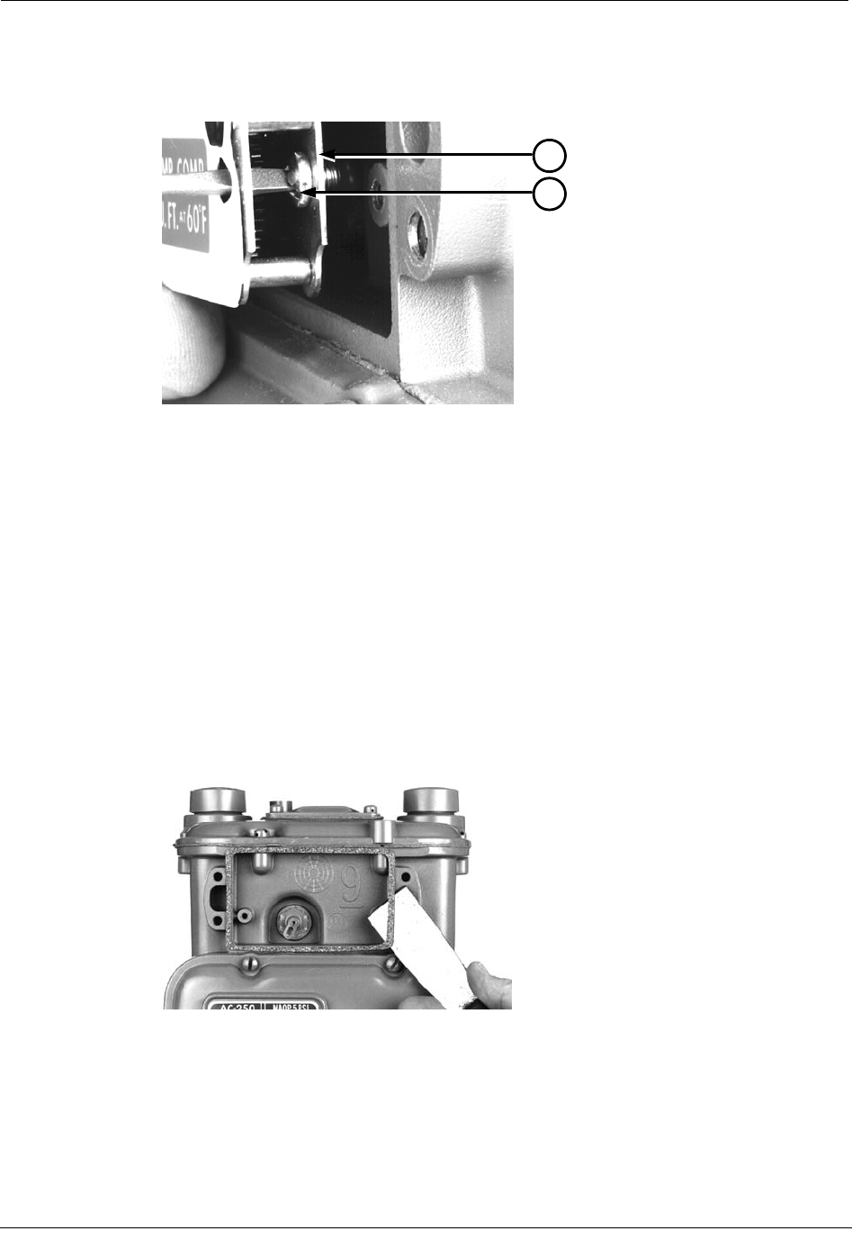
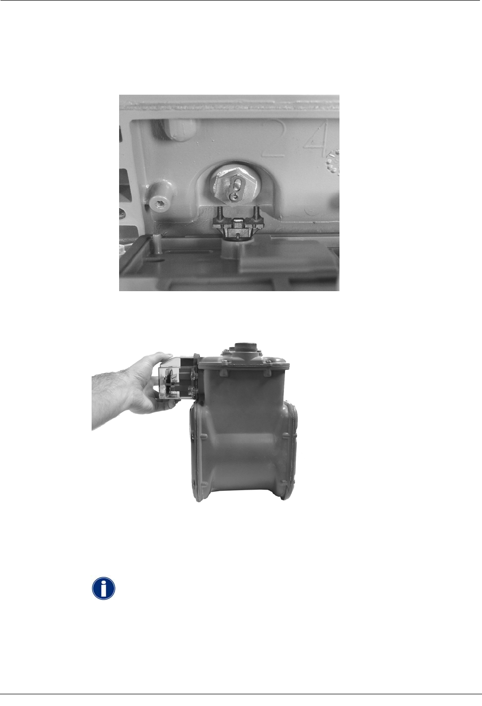
While removing this screw, pull the index away from the meter to keep its backplate
(1) against the back of the screwhead (2). This prevents the screw from falling out
prematurely.
1
2
6. Remove the screw from the index once it is completely free of its hole.
7. Set the index aside for the moment. Place it where it will not be damaged; get filled
with dirt, rain, or snow; or fall to the ground or floor. The index will be used later in
this procedure.
8. Examine the index screws you just removed. Verify that they are 3/16-inch long and
are not corroded.
• If the screws are 3/16-inch long and are not corroded, keep them for later use.
• If the screws are an incorrect length or are corroded, dispose of them properly.
Use 8 - 32 x 3/16-inch screws as described in Replacement Screws on page 14
instead.
9. Use a putty knife or similar object to completely remove the old index gasket from the
meter (if applicable). All traces of the gasket must be removed before the ERT can be
installed.
16 Natural Gas Solutions 100G Installation Guide
Installing the 100G ERT Module
Assemble the ERT Module
When installing a 100G ERT Module, the next major step is to create the endpoint module
assembly by combining the endpoint backplate and cover with the meter index. Follow the
procedure below to do so.
To assemble the ERT module
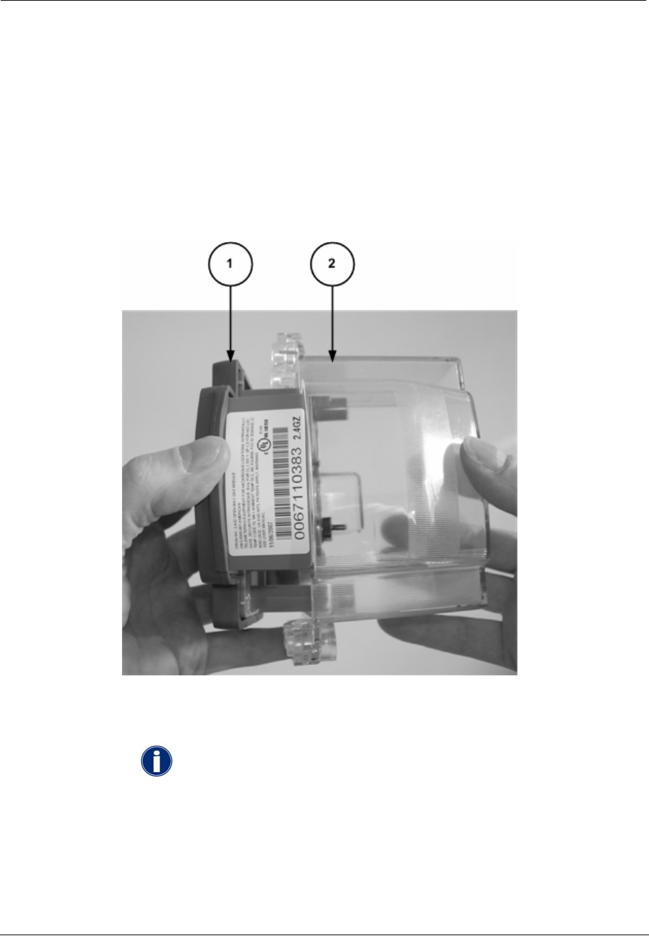
1. Obtain a new 100G ERT Module.
2. Separate the ERT module backplate (1) from the cover (2).
3. Set the new ERT index cover aside for the moment. Place it where it will not be
damaged; get filled with dirt, rain, or snow; or fall to the ground or floor. The ERT
index cover will be used later in this procedure.
IMPORTANT Before continuing with the installation, note the following
information about American Meter indexes:
Natural Gas Solutions 100G Installation Guide 17
Chapter 2 American Meter Installation
• Index wrigglers on one-foot meters have drive slots.
• Index wrigglers on two-foot meters have drive posts.
• An index may have mounting screw holes.
• An index may have mounting screw slots.
If the index has mounting screw slots, skip steps 4 and 5 below. Continue with step 6.
18 Natural Gas Solutions 100G Installation Guide
Installing the 100G ERT Module
If the index has mounting screw holes, perform steps 4 and 5 below, and then skip
steps 6 and 7.
4. If the index has mounting screw holes, place an index mounting screw (1) in the right-
hand mounting screw hole (2). Use one 8 - 32 3/16-inch screw for this step (you can
use an original mounting screw if it was the correct size and not corroded; otherwise,
use the correct size replacement screw).
1
2
5. Attach the screw to the ERT backplate's right-hand index mounting post just far
enough to hold the screw and end of the index in place.
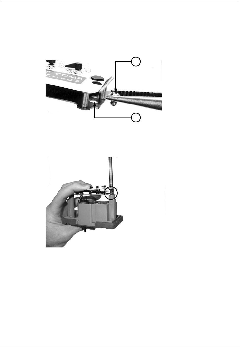
6. If the index has mounting screw slots, screw an index mounting screw (1) one to two
turns into the ERT backplate's right-hand index mounting post (2). Use one 8 - 32 x
3/16-inch screw for this step (you can use an original mounting screw if it was the
correct size and not corroded; otherwise, use the correct size replacement screw).
Natural Gas Solutions 100G Installation Guide 19
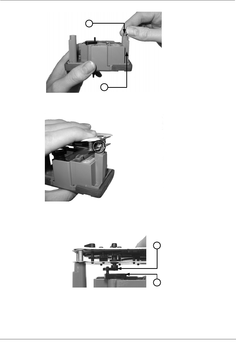
Chapter 2 American Meter Installation
2
1
7. Place the index mounting screw slot under the screw head. Do not tighten the screw
yet.
2
1
8. Attach the wriggler to the index and backplate.
• If the index wriggler has a drive slot (1), place the backplate wriggler's drive
post (2) in the index wriggler's drive slot.
2
1
20 Natural Gas Solutions 100G Installation Guide
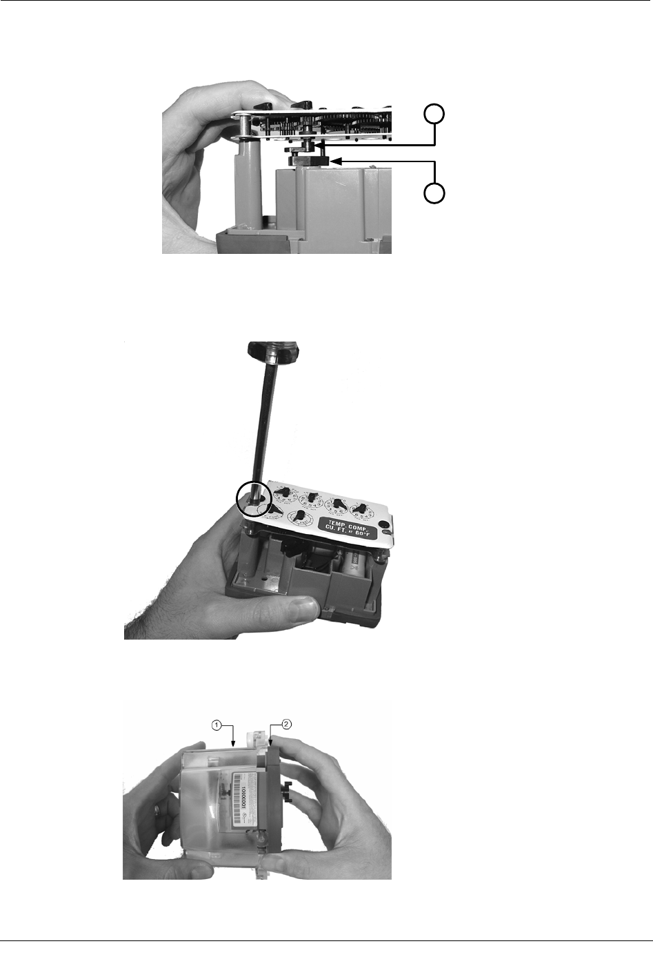
Installing the 100G ERT Module
• If the index wriggler has a drive post (1), place the index wriggler's drive post
in the backplate wriggler's drive slot (2).
2
1
9. Install and tighten the left-hand index mounting screw (for indexes with either
mounting screw slots or holes). Use one 8 - 32 x 3/16-inch screw for this step (you
can use an original mounting screw if it was the correct size and not corroded;
otherwise, use the correct size replacement screw).
10. Tighten the right-hand index mounting screw.
11. Slide the ERT cover (1) over the index and backplate (2).
Next, program the ERT module.
Natural Gas Solutions 100G Installation Guide 21
Chapter 2 American Meter Installation
Program the ERT Module
The ERT must be programmed using the FC200SR with EndPoint-Link software. See the
Endpoint-Link ERT Programming Guide (TDC-0411) for more information.
IMPORTANT You must perform the following programming procedure for
the ERT module to function properly.
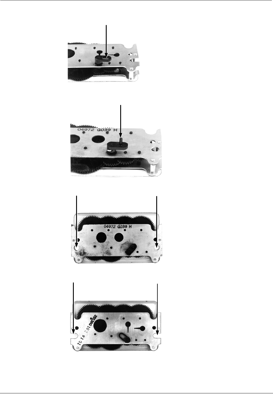
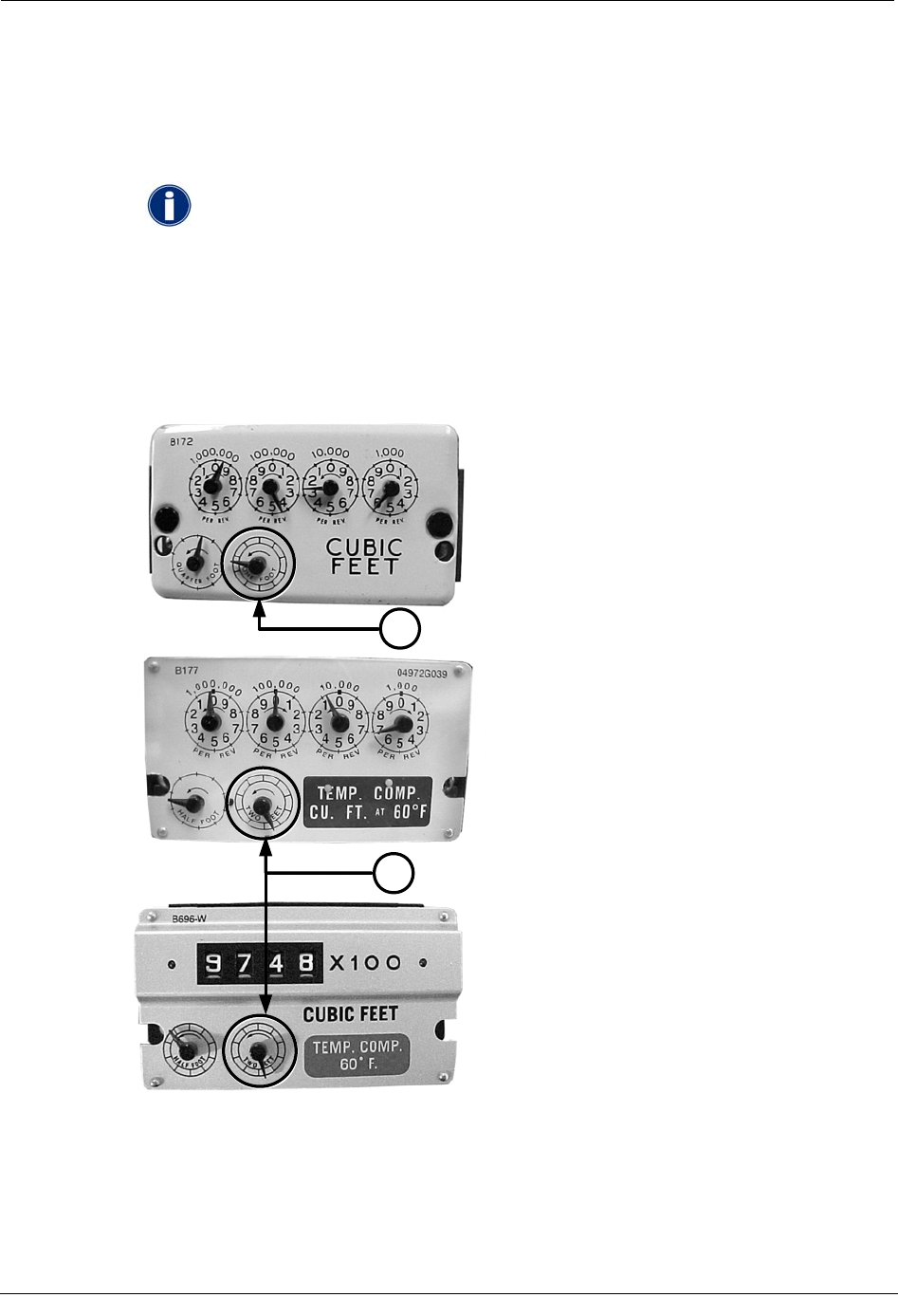
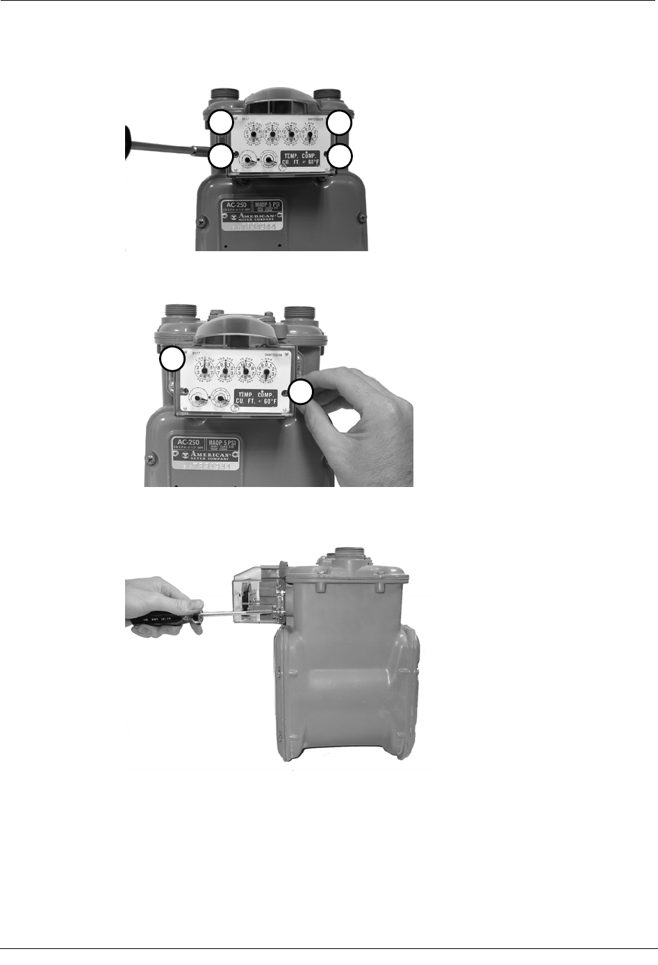
When programming the ERT module, you must take note of the drive rate shown on the
index of the meter. Program the meter based on the drive rate shown on the index.
American meters. Examples of 1-foot (1) and 2-foot (2) drive rates are shown below (a 0.05
cubic metre drive rate is not shown). Be sure to program the ERT based on the drive rate
indicated on the index.
1
2
To program the ERT module
1. Using the FC200SR, program the reading of the index that was on the meter into the
ERT module assembly.
22 Natural Gas Solutions 100G Installation Guide

Installing the 100G ERT Module
• For initial programming, hold the FC200SR approximately 1 foot away from
the 100G.
• For reprogramming (30 days or more past initial programming), hold the
FC200SR approximately 4 to 5 feet away from the 100G.
Be sure to program the 100G to the correct mode for the reading technology what will
be used (for example, Fixed Network Mode, Mobile/Handheld Mode, or Hard to Read
Mobile/Handheld Mode). In Endpoint-Link Pro v5.0, you will have access to the one
mode that was defined by your system administrator.
During programming, the 100G ERT module is programmed to the nearest 100 cubic
feet; the last two digits (the tens and units) are programmed as zeros (0). Once
programming is complete, however, the ERT module assembly can be read to the
nearest cubic foot.
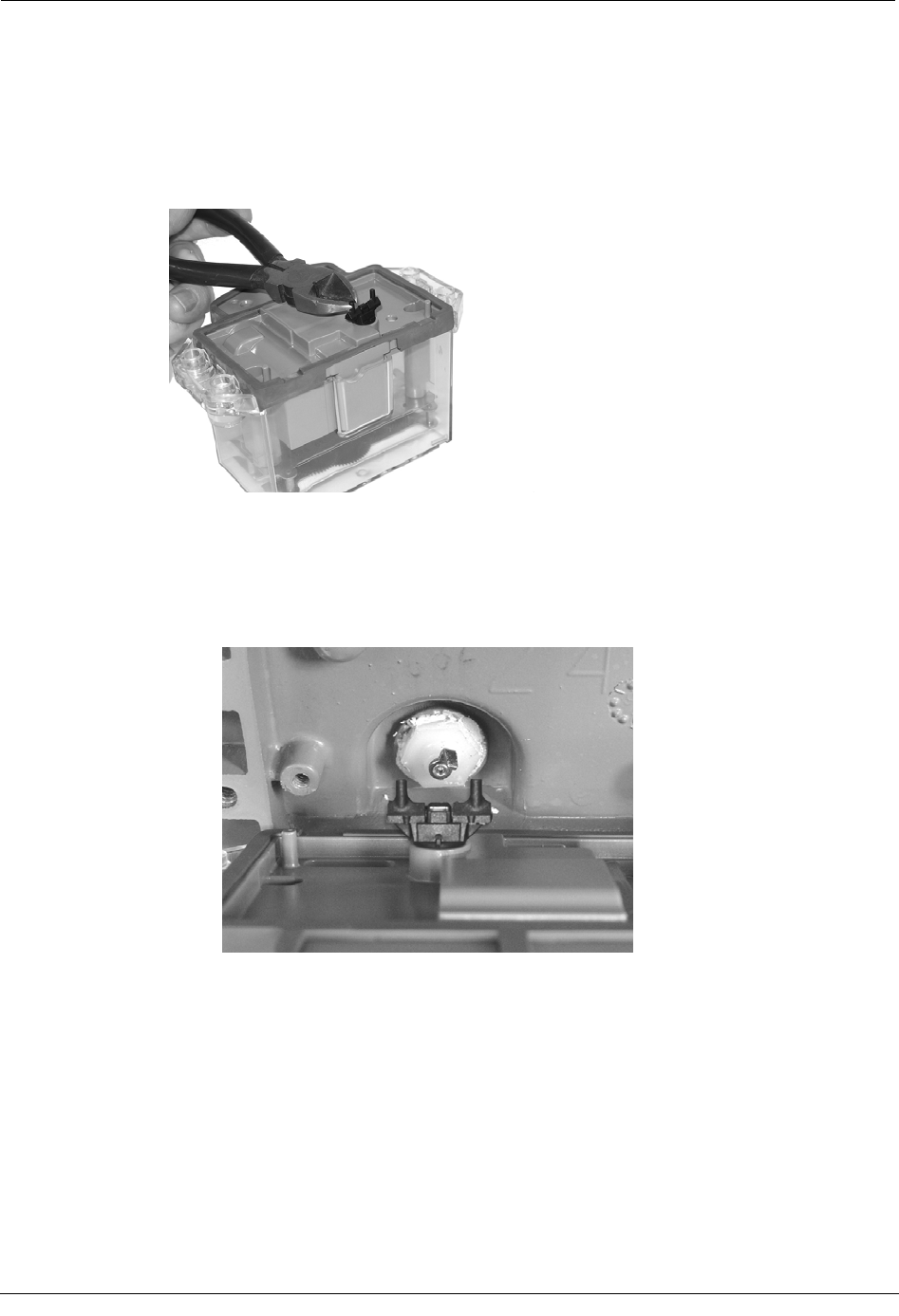
2. Slowly turn the ERT module drive wriggler two turns in the direction indicated on the
index drive rate. This lets you verify the ERT module is counting properly after
assembly.
IMPORTANT Do not turn the drive wriggler faster than one turn per second.
3. Read the ERT module assembly using the FC200SR. Consult the EndPoint-Link ERT
Programming Guide (TDC-0411) or other applicable instructions for details on how to
read an ERT.
• If this reading is higher than the one you programmed in step 1 above, the ERT
module assembly is counting correctly.
• If the ERT module assembly reading is not higher than what was programmed
in step 1, replace the ERT module with a new one.
Attach the ERT Module to the Meter
After the endpoint has been programmed and is reading correctly, it must be attached to the
meter. Follow the steps below to do this.
Natural Gas Solutions 100G Installation Guide 23
Chapter 2 American Meter Installation
To Attach the ERT to the Meter
1. 5B 225 Meters Only If you are installing the ERT on a 5B 225 aluminum meter, cut
1/16-inch off each post of the ERT wriggler to prevent it from rubbing on the face of
the nut that holds the wriggler in place. If you are not installing on a 5B 225 meter,
continue to step 2 below.
2. Set the wriggler to the desired position for mounting the ERT module assembly to the
meter.
• For One-Foot Meters: Align the ERT module assembly wriggler with the
meter drive post (as shown below). Make sure the ERT wriggler is
perpendicular to the meter drive post.
24 Natural Gas Solutions 100G Installation Guide
Installing the 100G ERT Module
• For Two-Foot Meters: Align the ERT module assembly wriggler with the
meter drive slot (as shown below). It is acceptable for the pin on the 100G
wriggler to be installed inside or outside of the meter drive slot. For ease of
assembly, Itron recommends that the pin on the 100G wriggler be installed
outside of the meter drive slot.
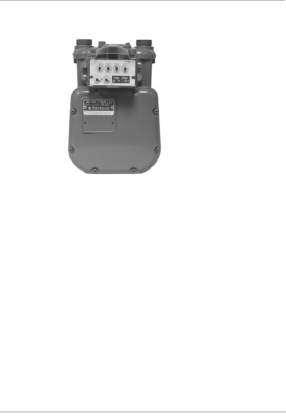
3. Gently place the ERT module assembly on the meter. Align the four screw holes on
the ERT module assembly with the holes on the meter.
4. Turn each screw 1/4 to 1/2 turn after it contacts the cover. Use the 1/4 - 20 x 5/8-inch
screws for this step. You can use the original mounting screws if they were the correct
size and not corroded, otherwise, use the correct size Replacement Screws on page 14.
IMPORTANT Meter manufacturers should torque the mounting screws 15 to 20
inch-pounds.
Natural Gas Solutions 100G Installation Guide 25
Chapter 2 American Meter Installation
3
41
2
5. Place a new tamper seal over two of the mounting screws as shown below.
1
2
6. Press the new tamper seals into place using the 11/32-inch nut driver (or another
similar blunt tool).
7. Complete any necessary paperwork. Make sure no excess material is left on the
customer premises; dispose of it properly.
26 Natural Gas Solutions 100G Installation Guide
Installing the 100G ERT Module
The ERT is now installed on the meter.
Natural Gas Solutions 100G Installation Guide 27