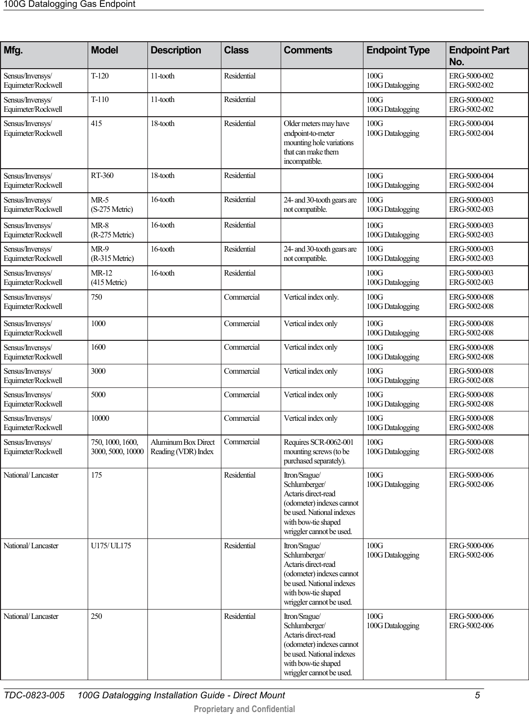
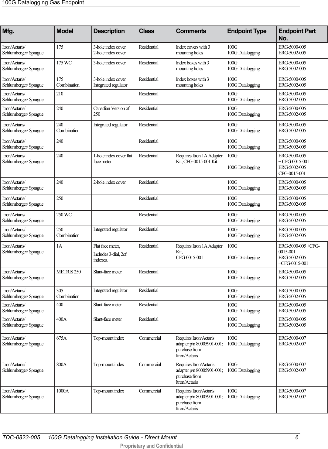
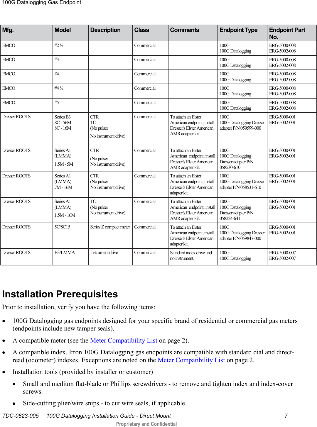
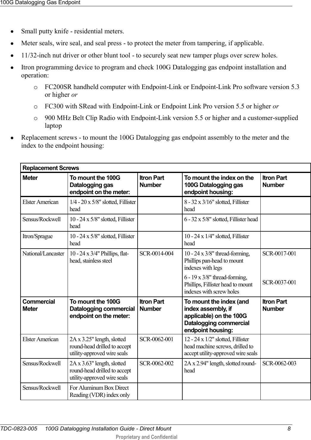
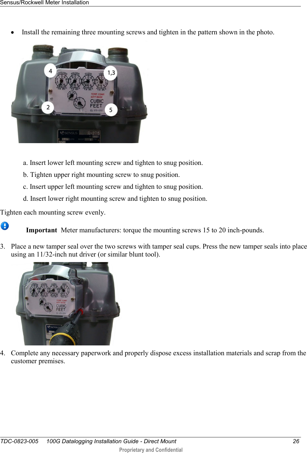
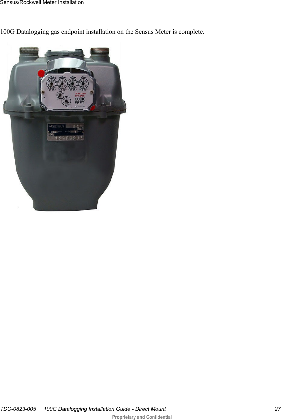
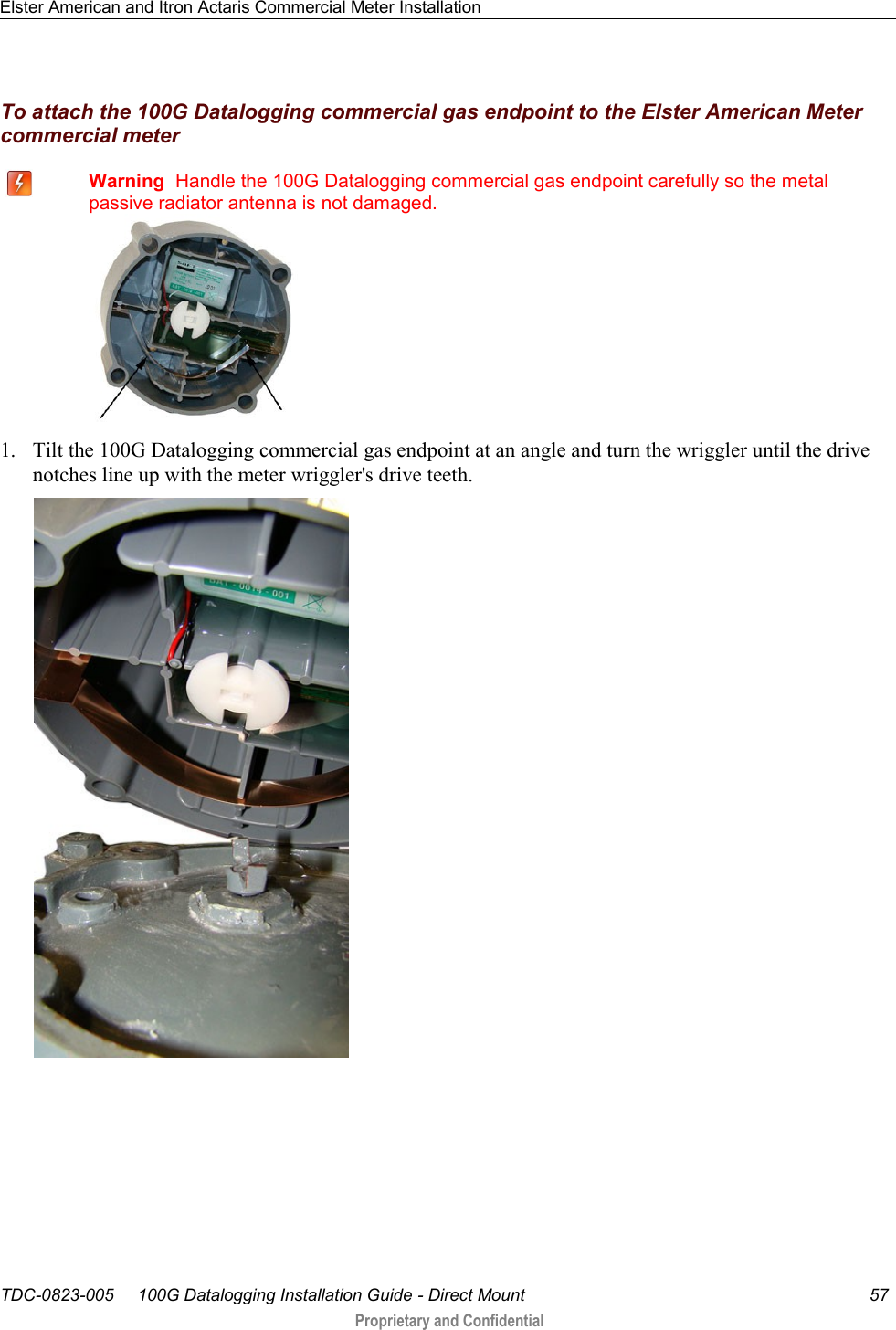
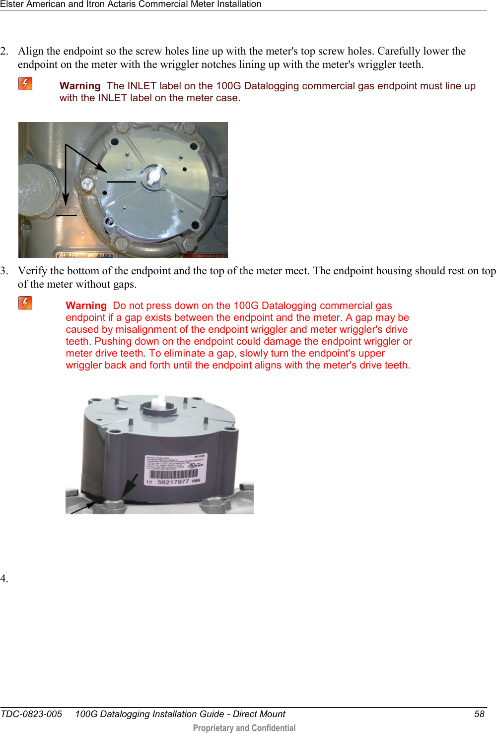
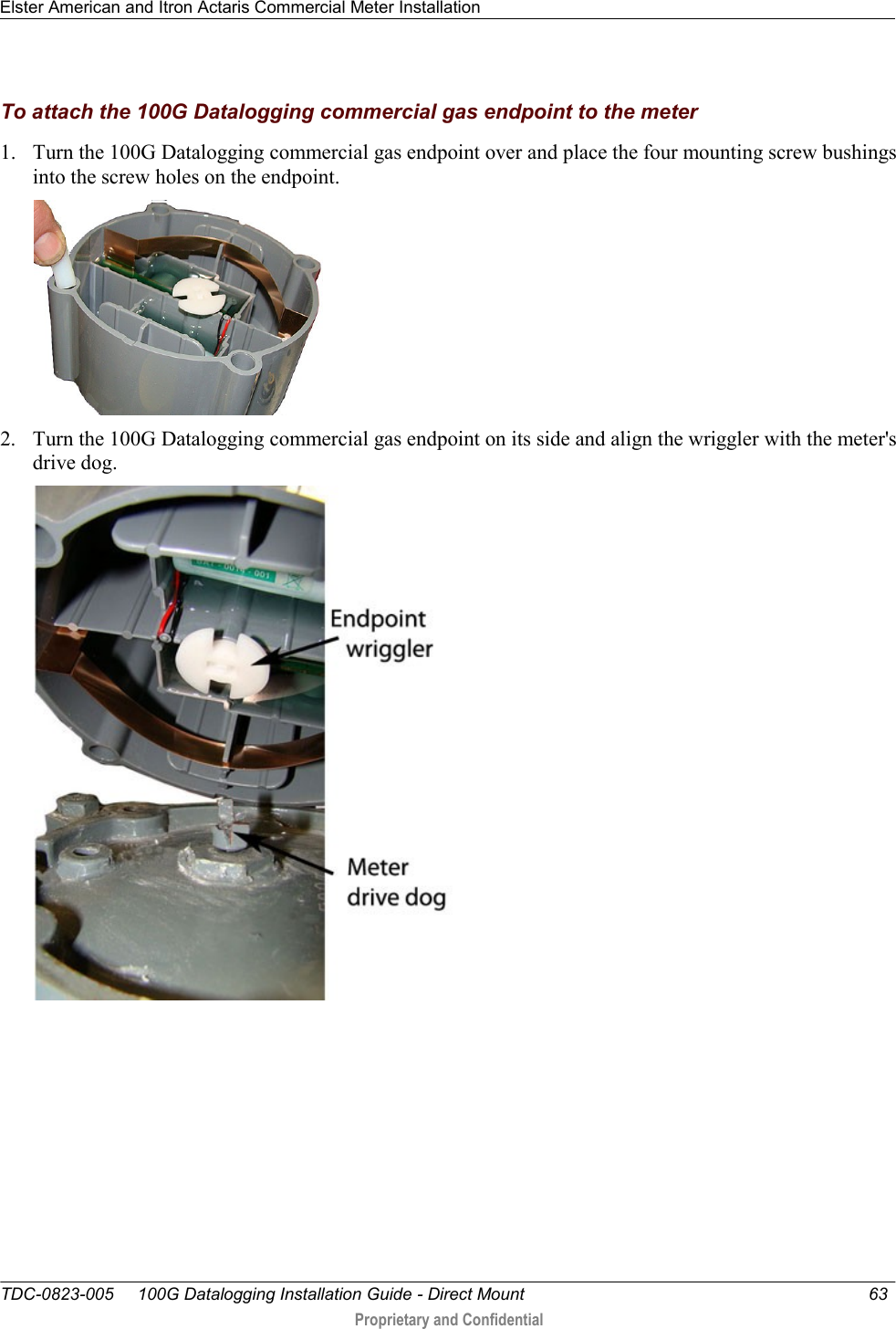
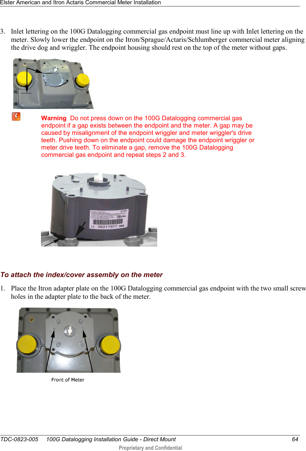
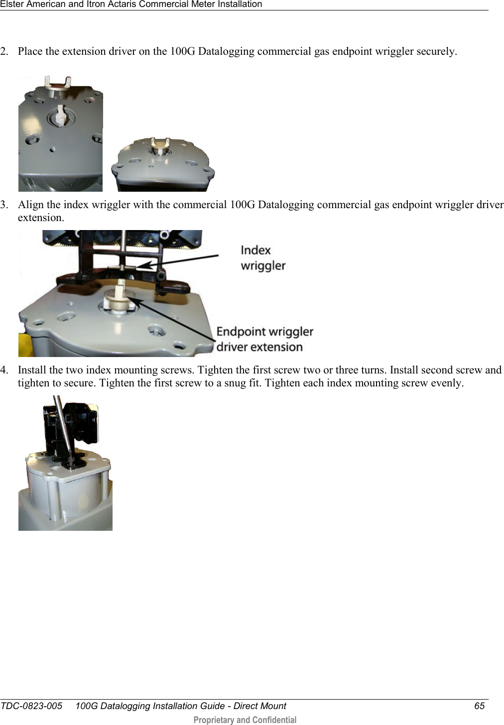
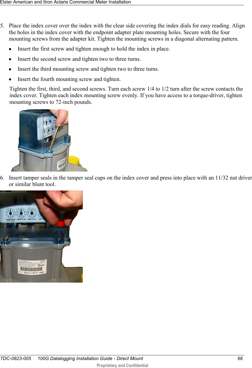
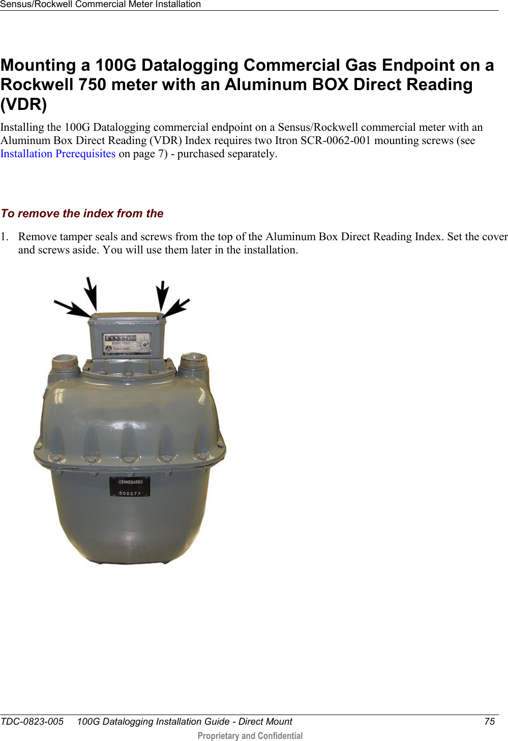
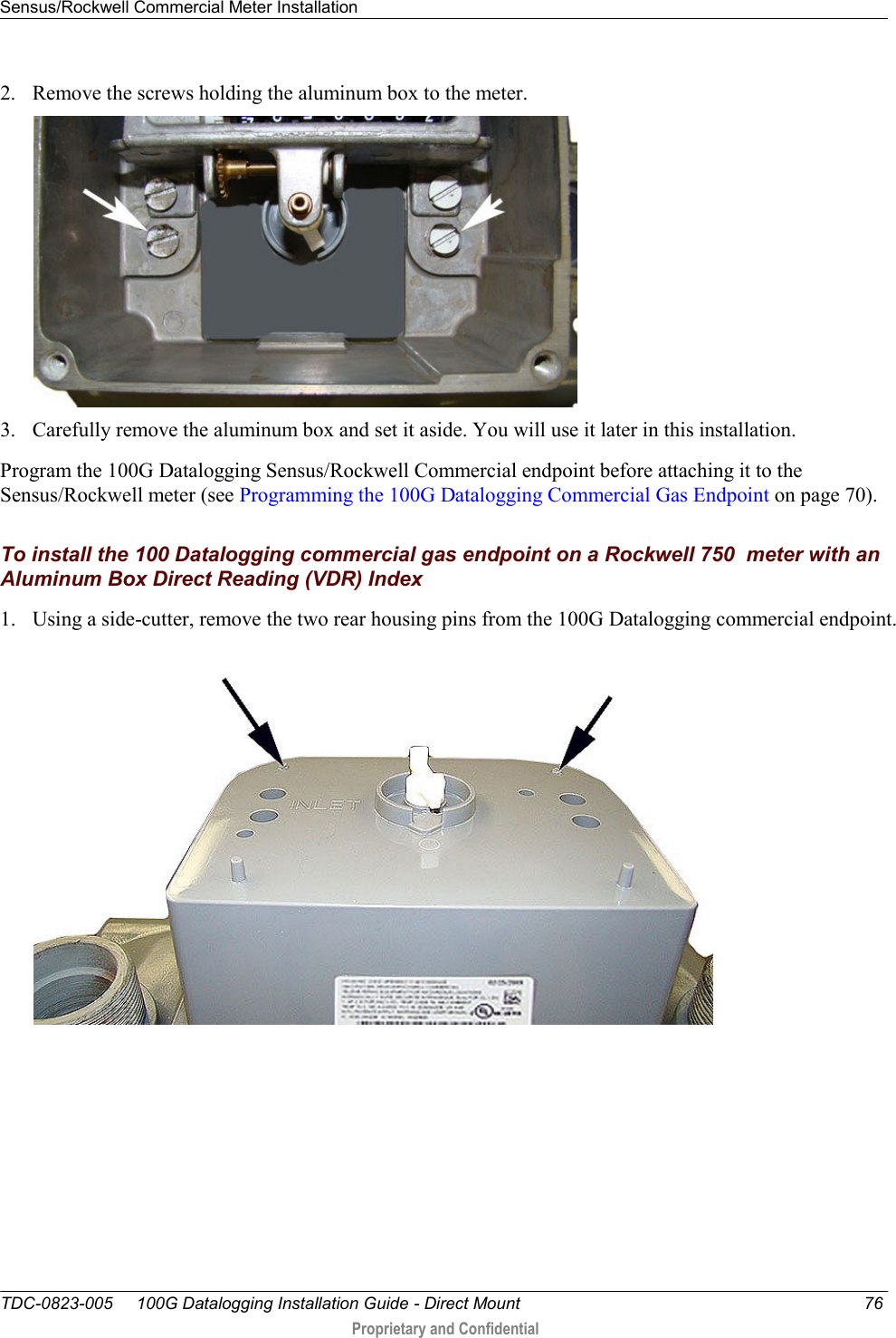
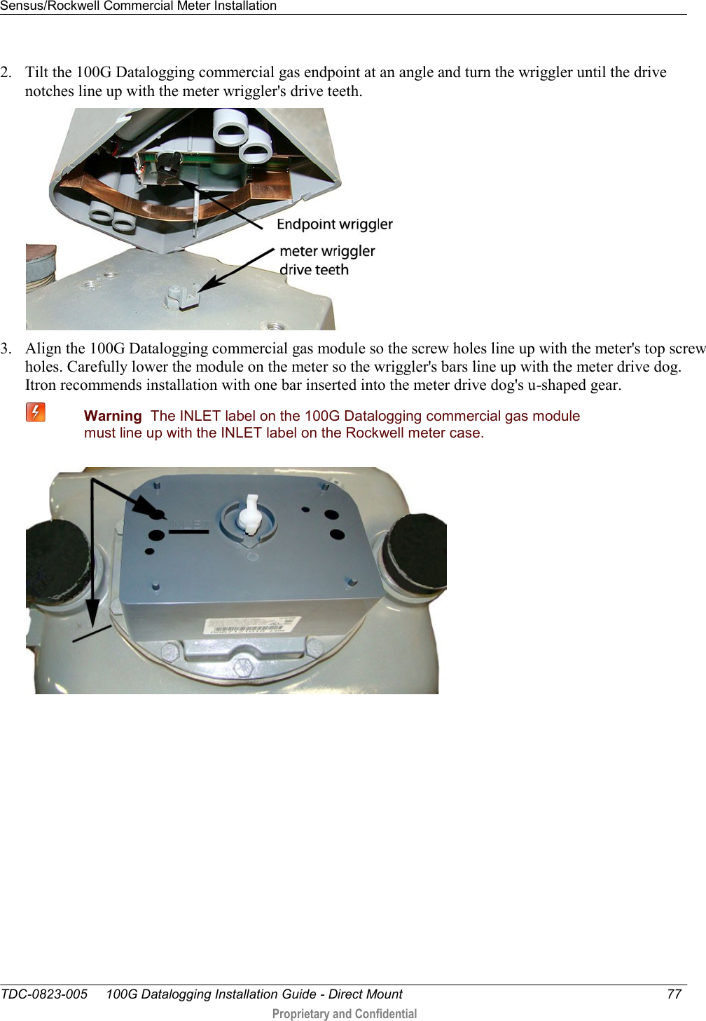
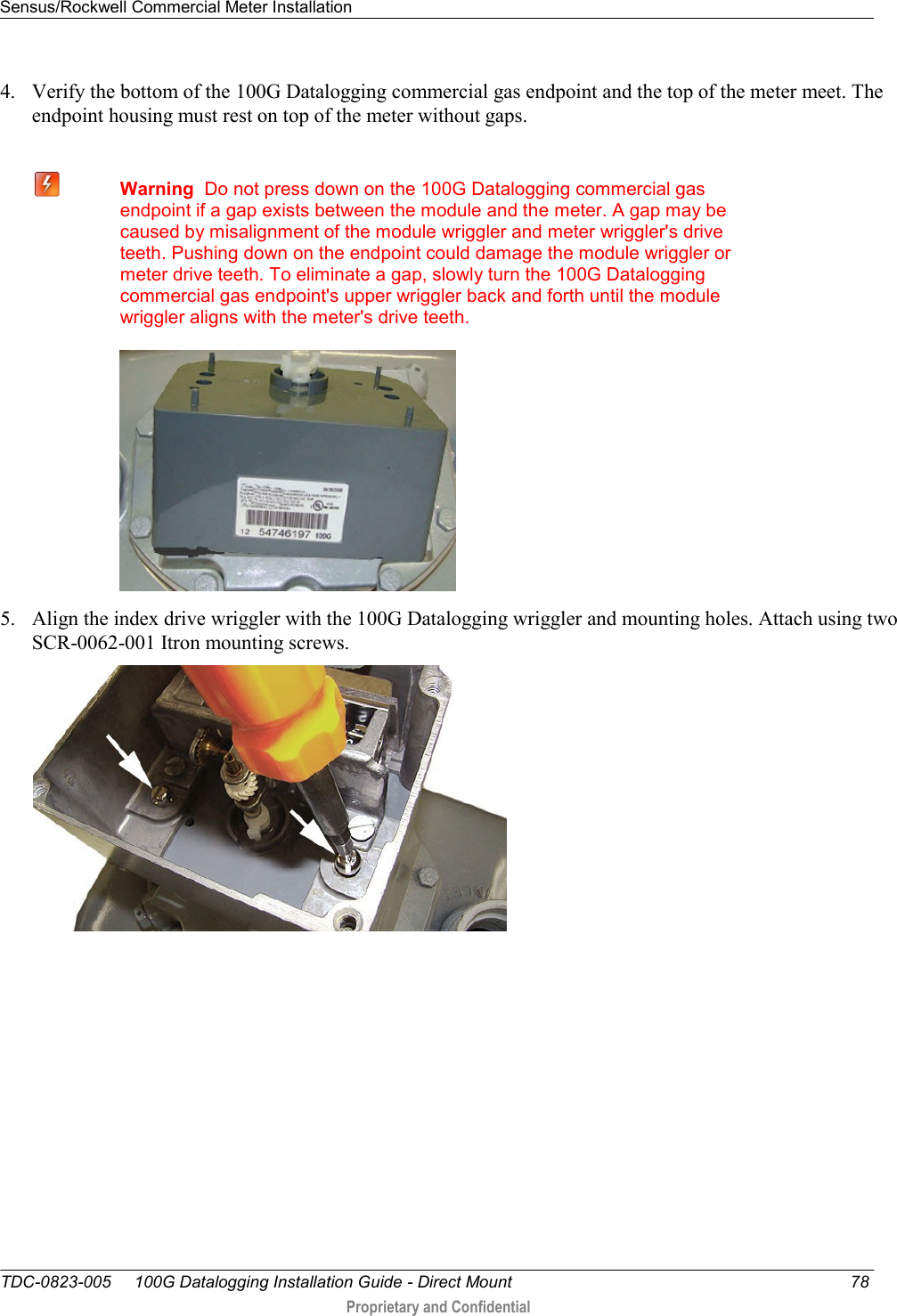
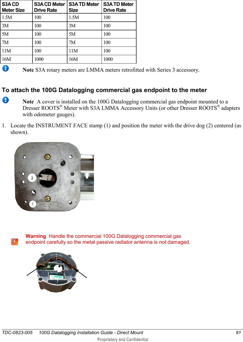
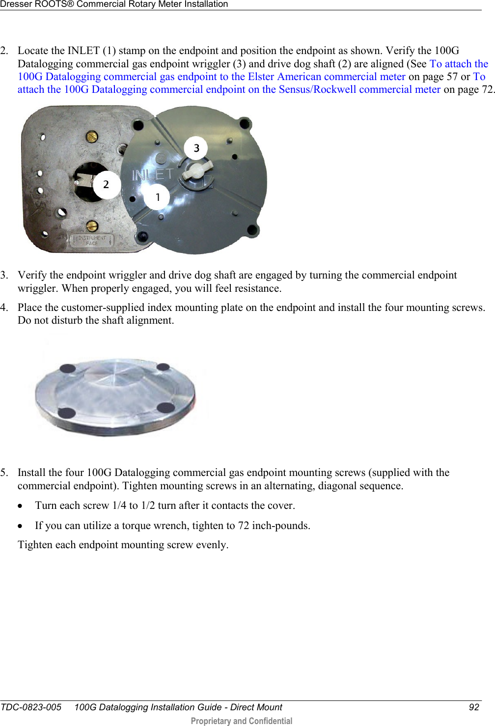
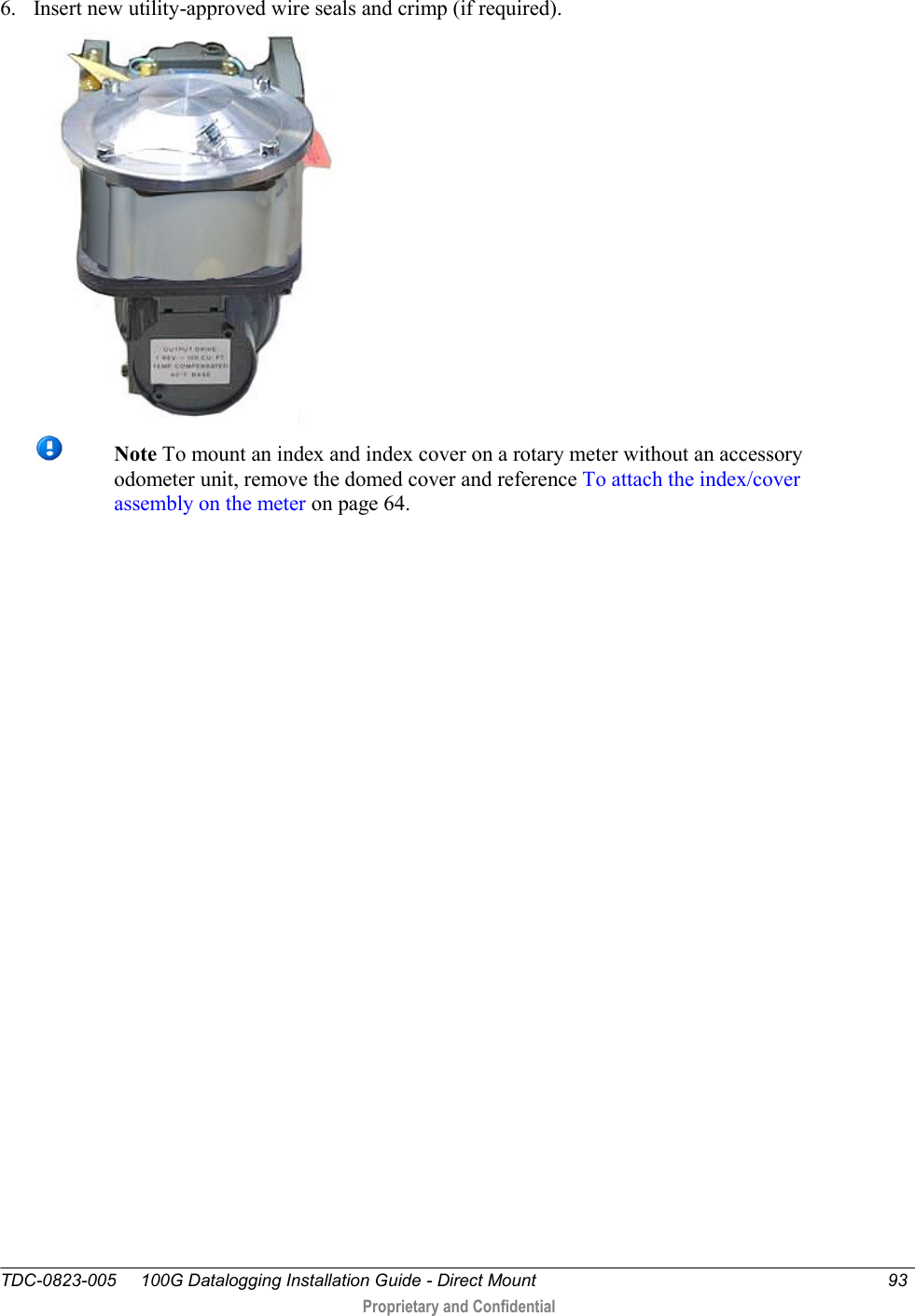
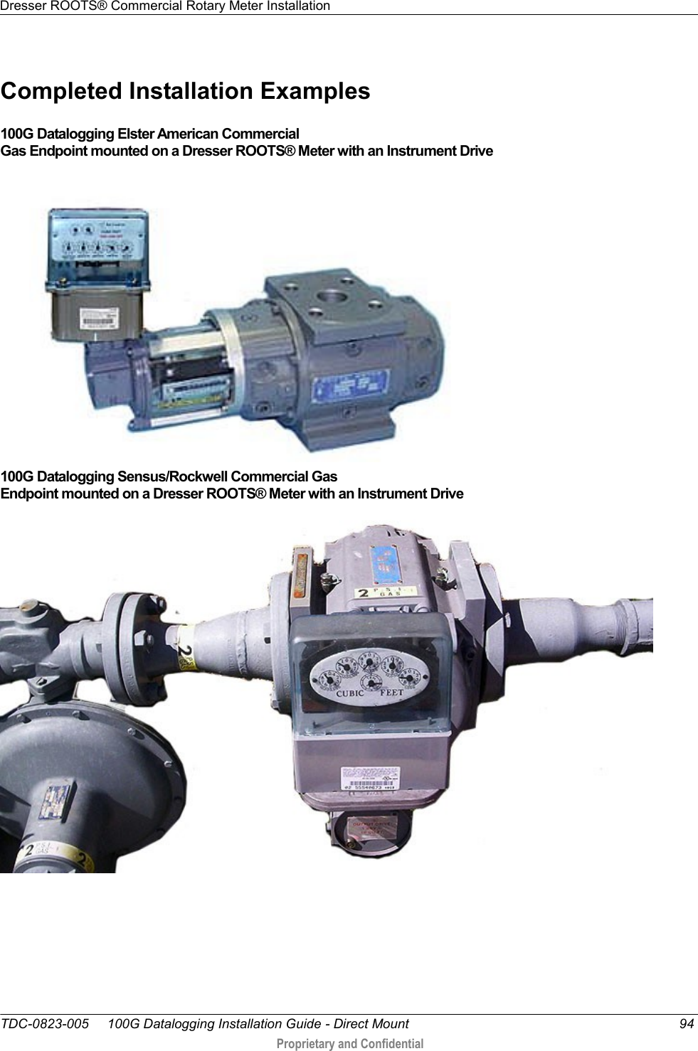
Itron 100GDLAN AMR transceiver device for utility meters User Manual 100G Datalogging Installation Guide Direct Mount
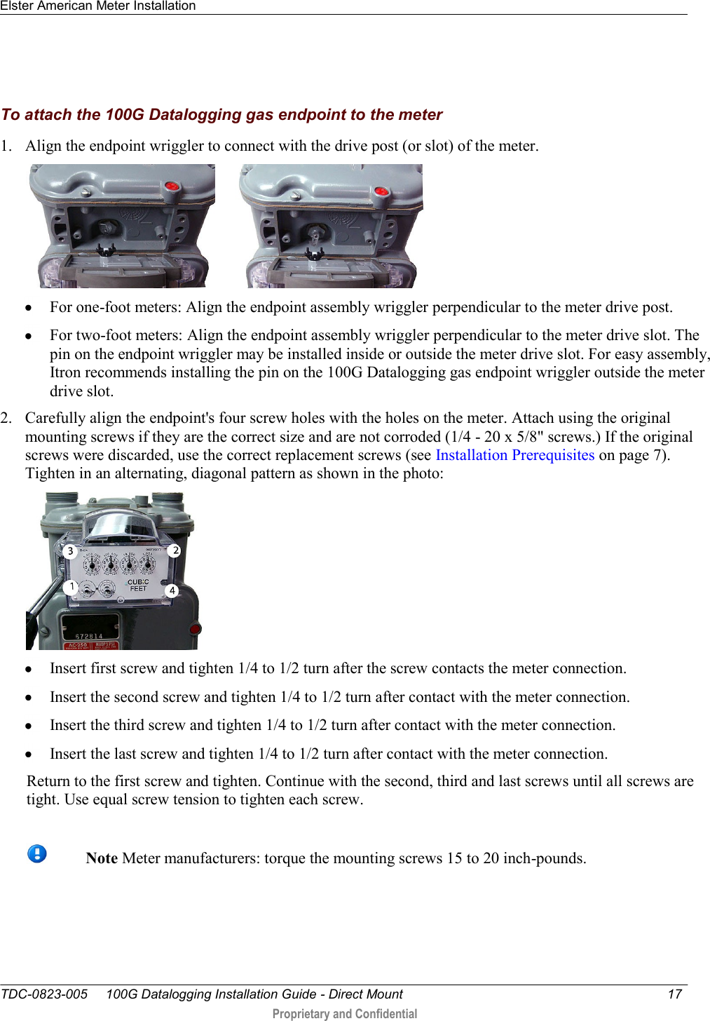
Itron Inc AMR transceiver device for utility meters 100G Datalogging Installation Guide Direct Mount
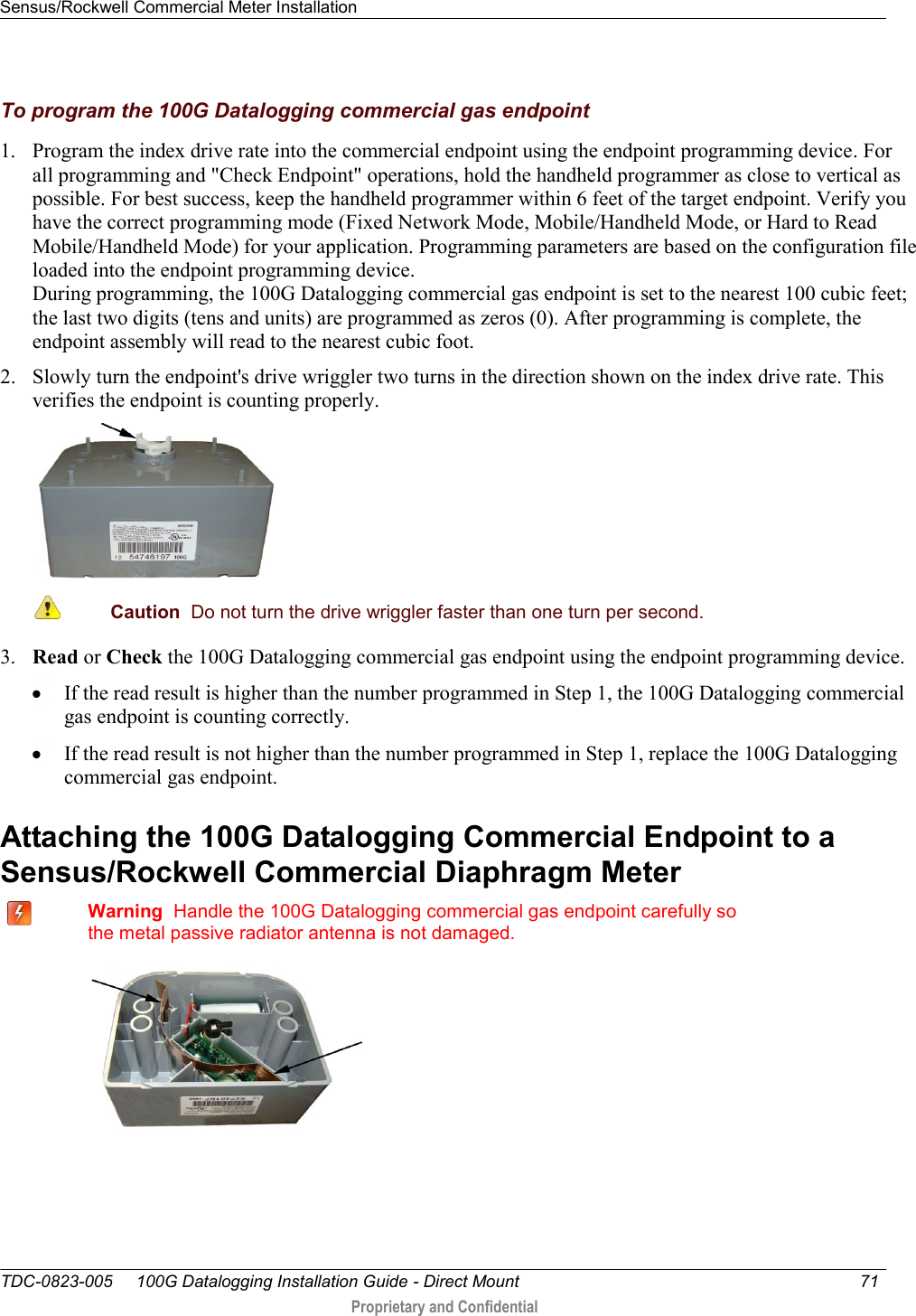
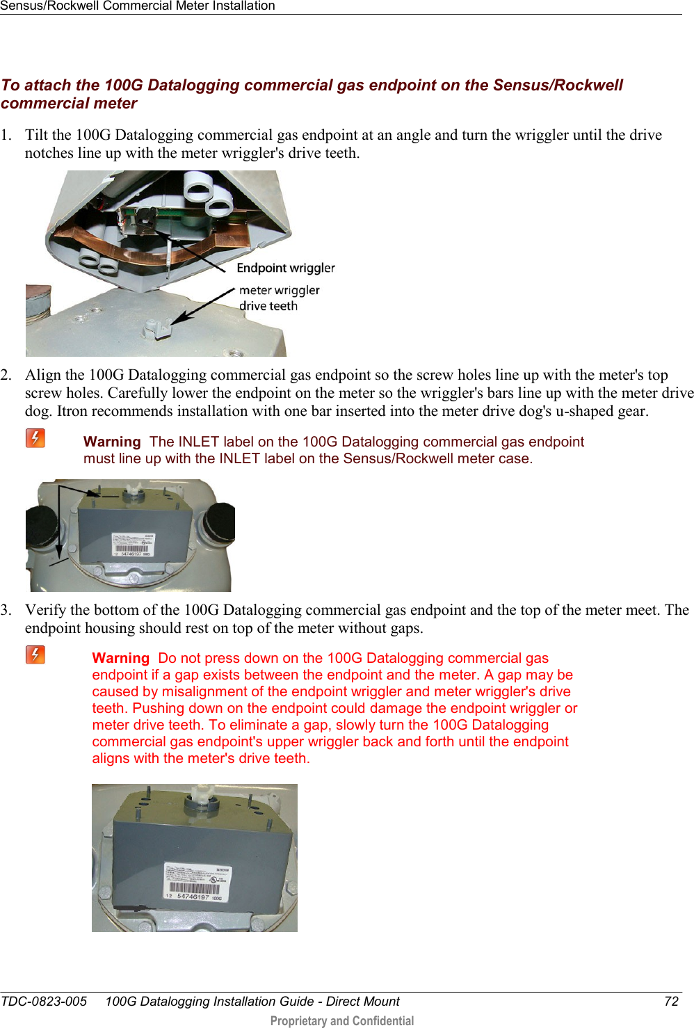
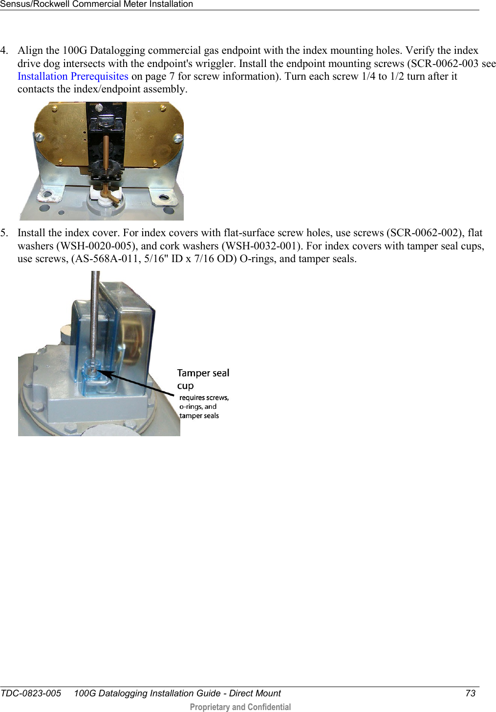
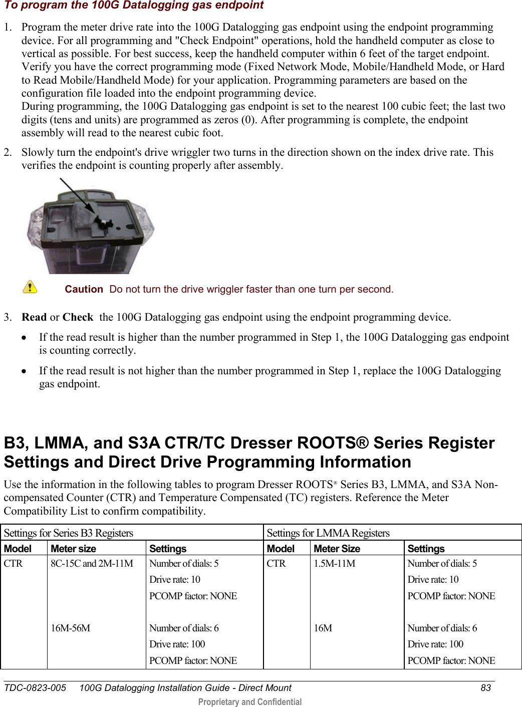
Itron >
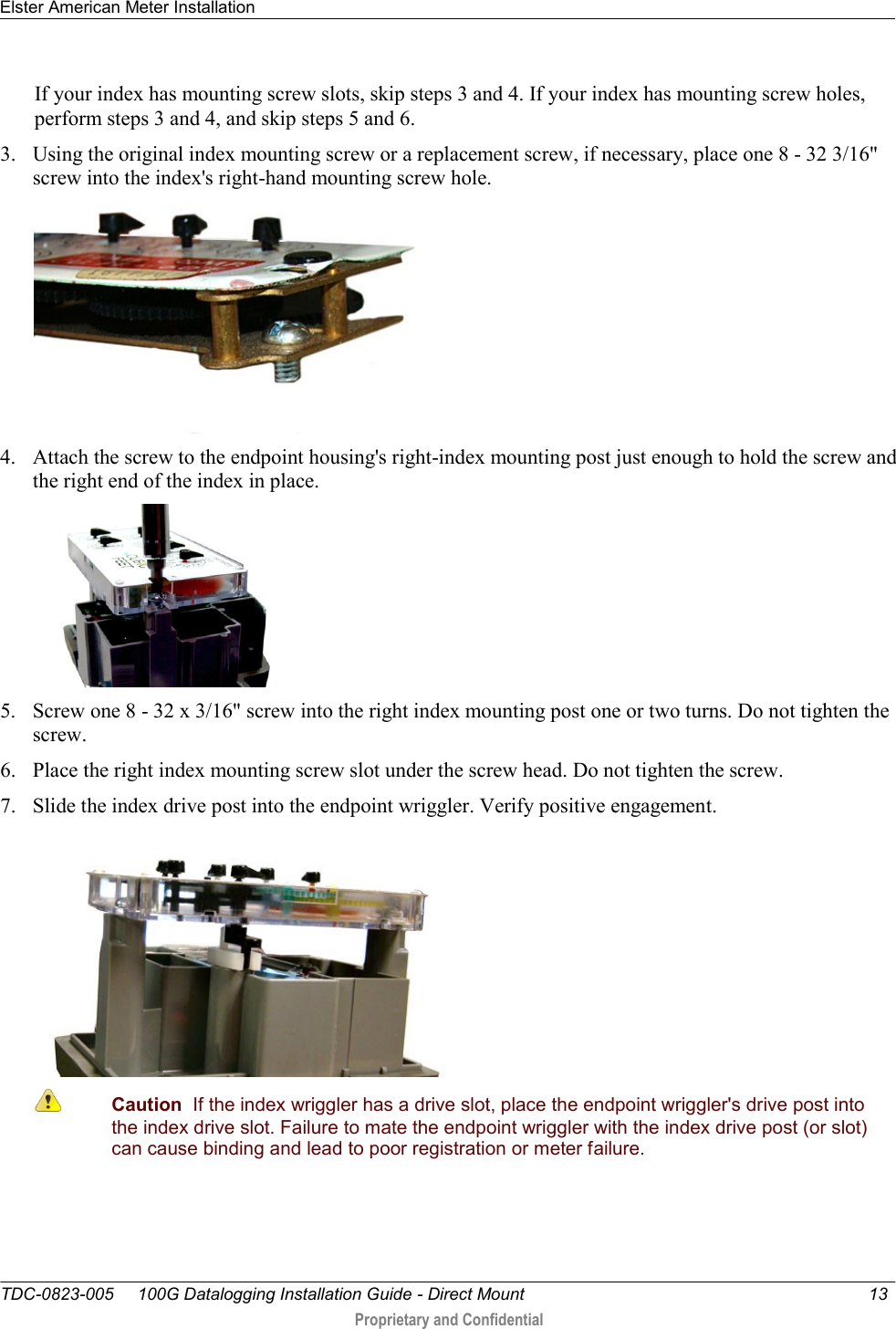
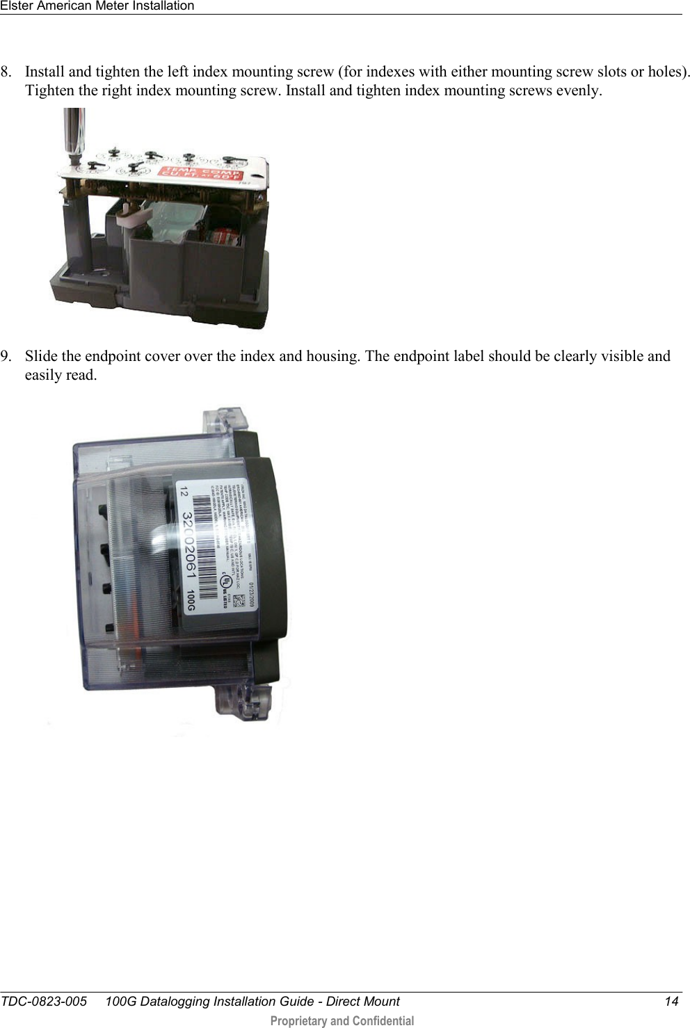
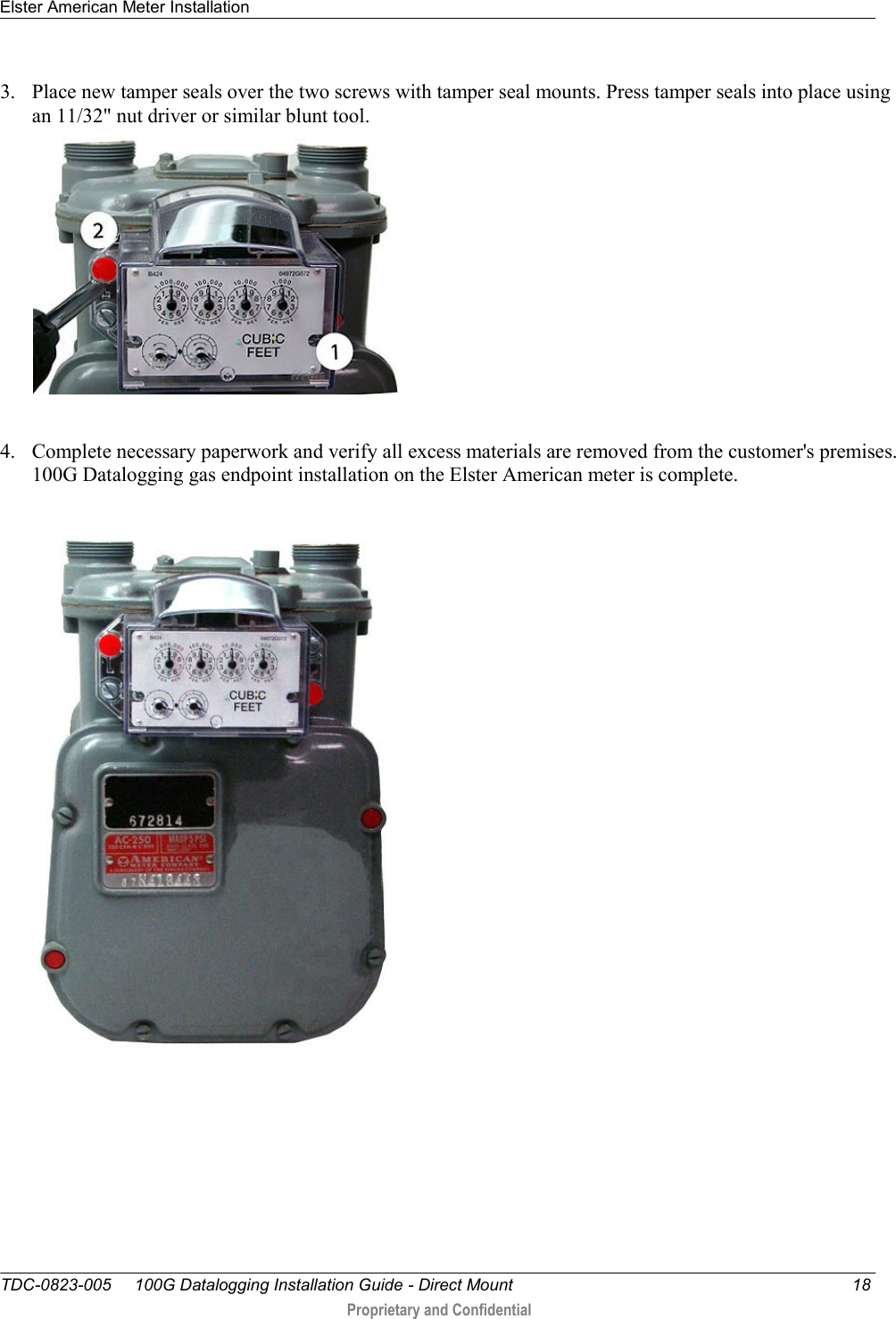
Contents
- 1. Users Manual 1
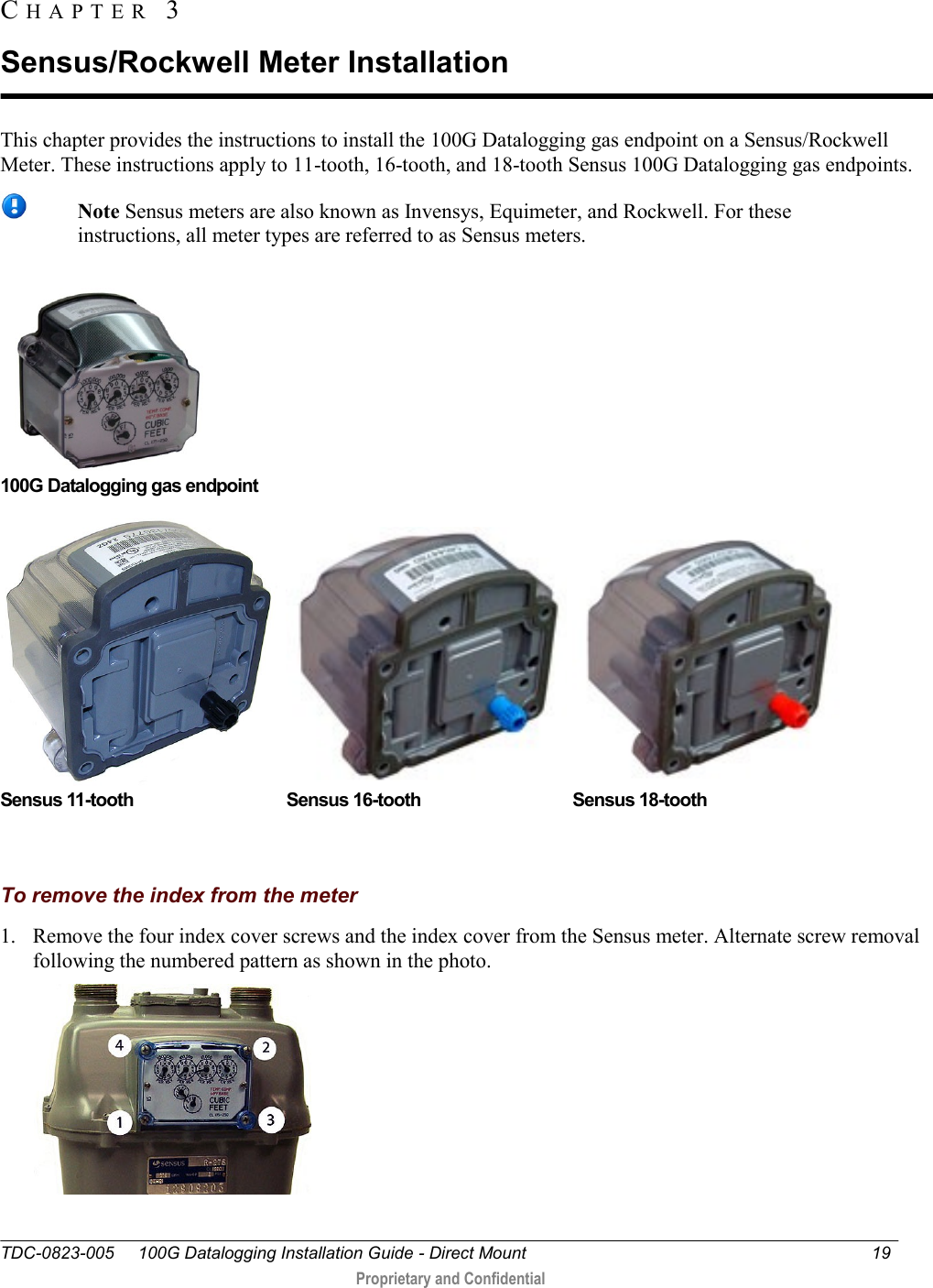
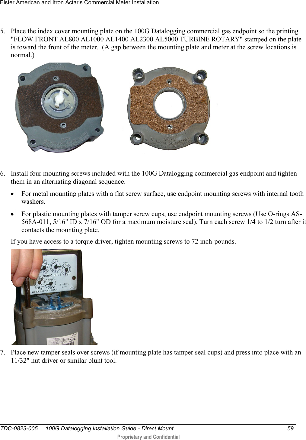
- 2. Users Manual 2
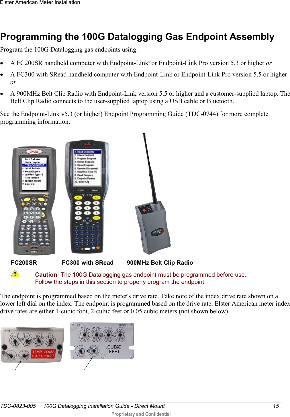
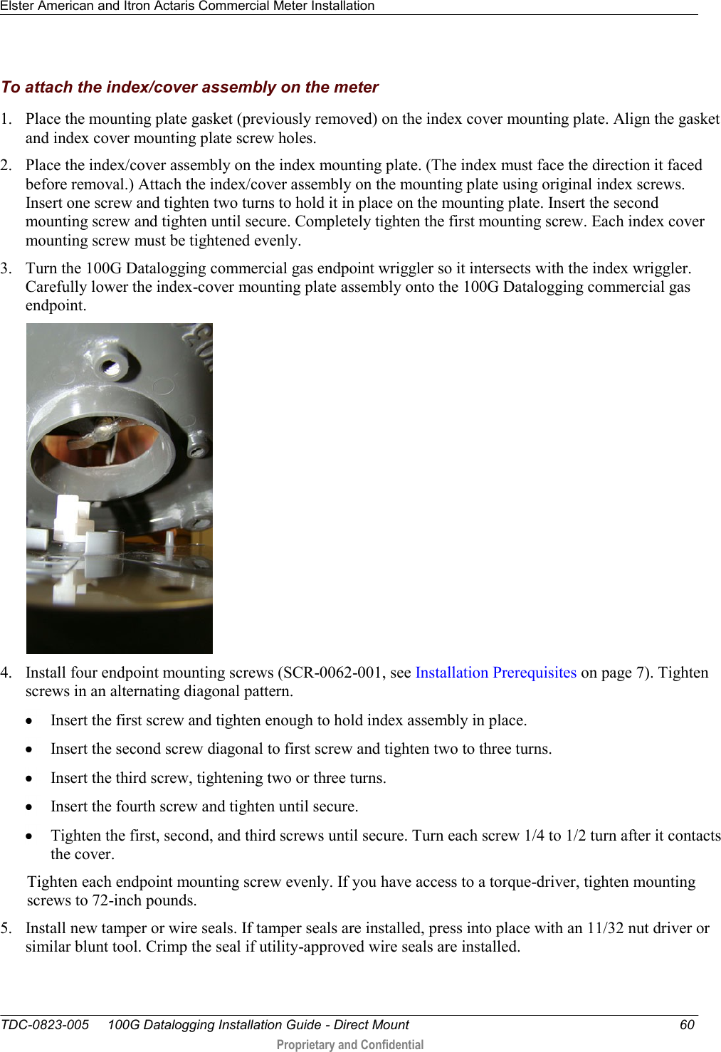
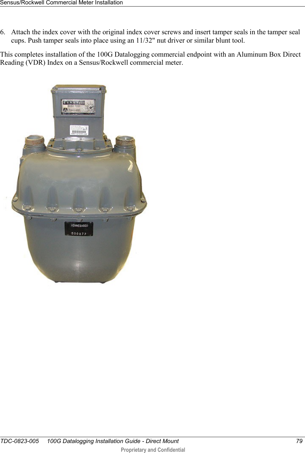
- 3. Users Manual 3
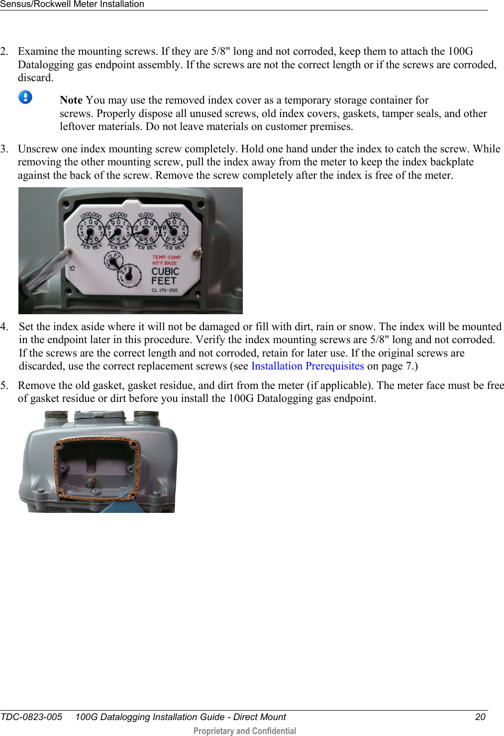
- 4. Users Manual 1
Users Manual 1
Users Manual 1