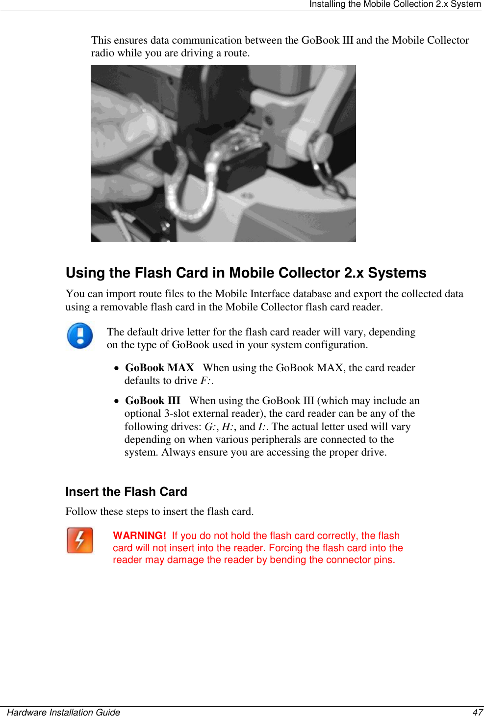
Itron DCU5310 Mobile collection device for utility metering User Manual Hardware Installation Guide
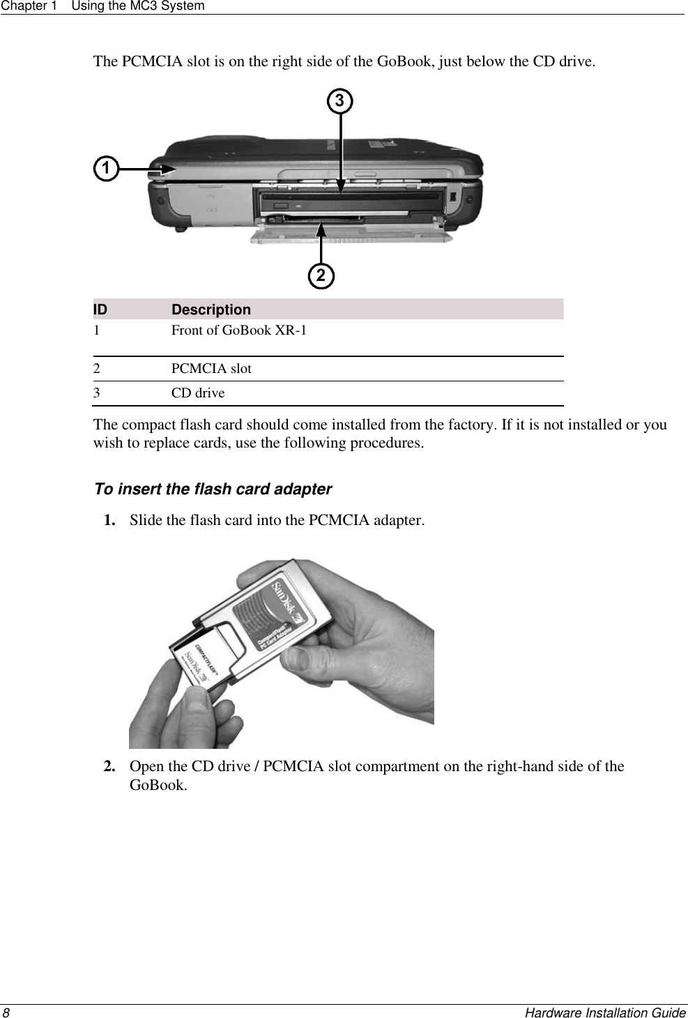
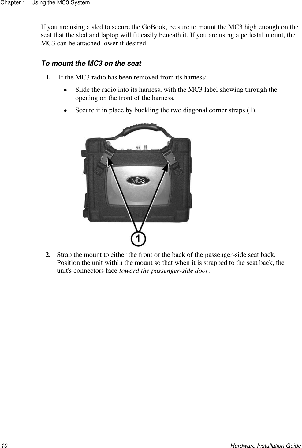
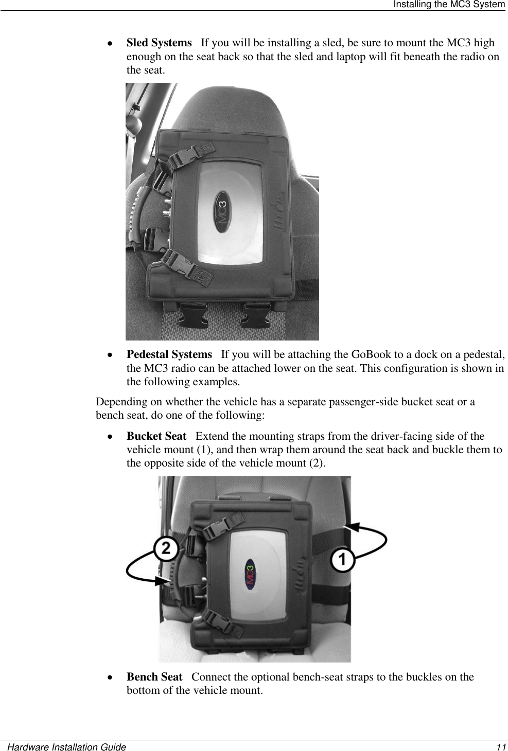
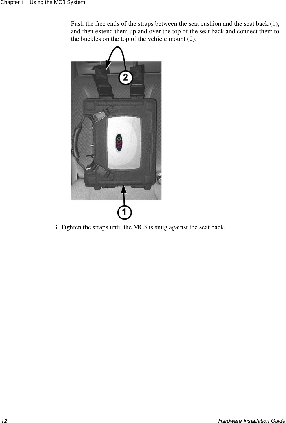
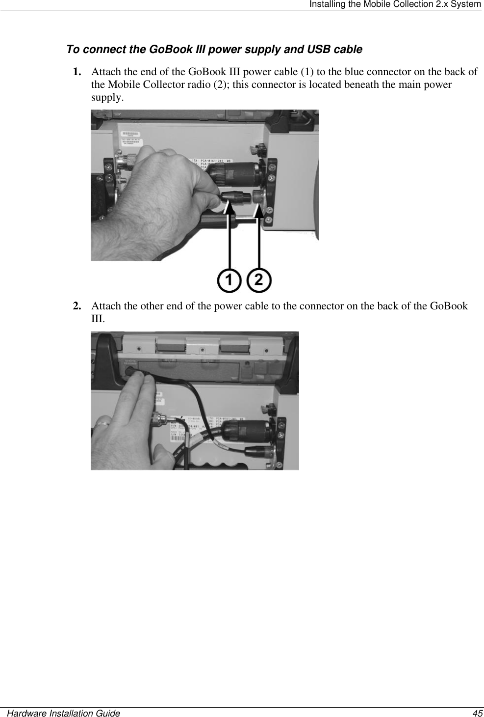
Itron, Inc. Mobile collection device for utility metering Hardware Installation Guide
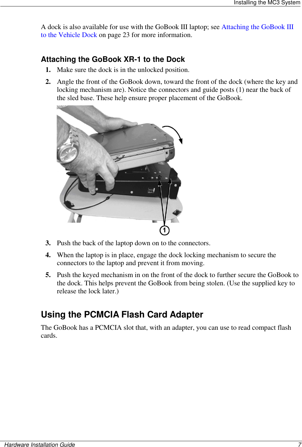
Itron >
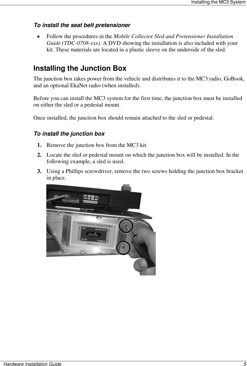
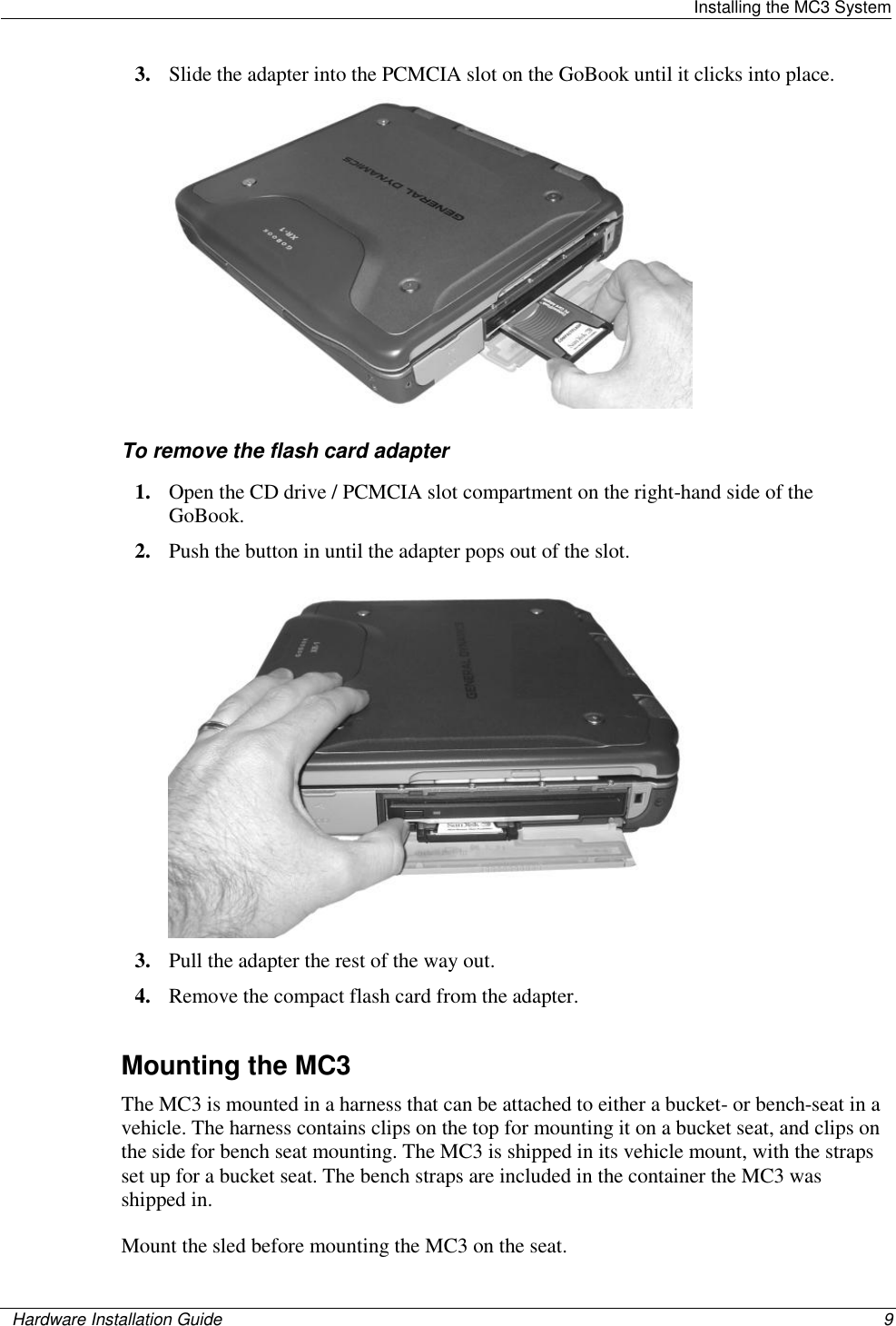
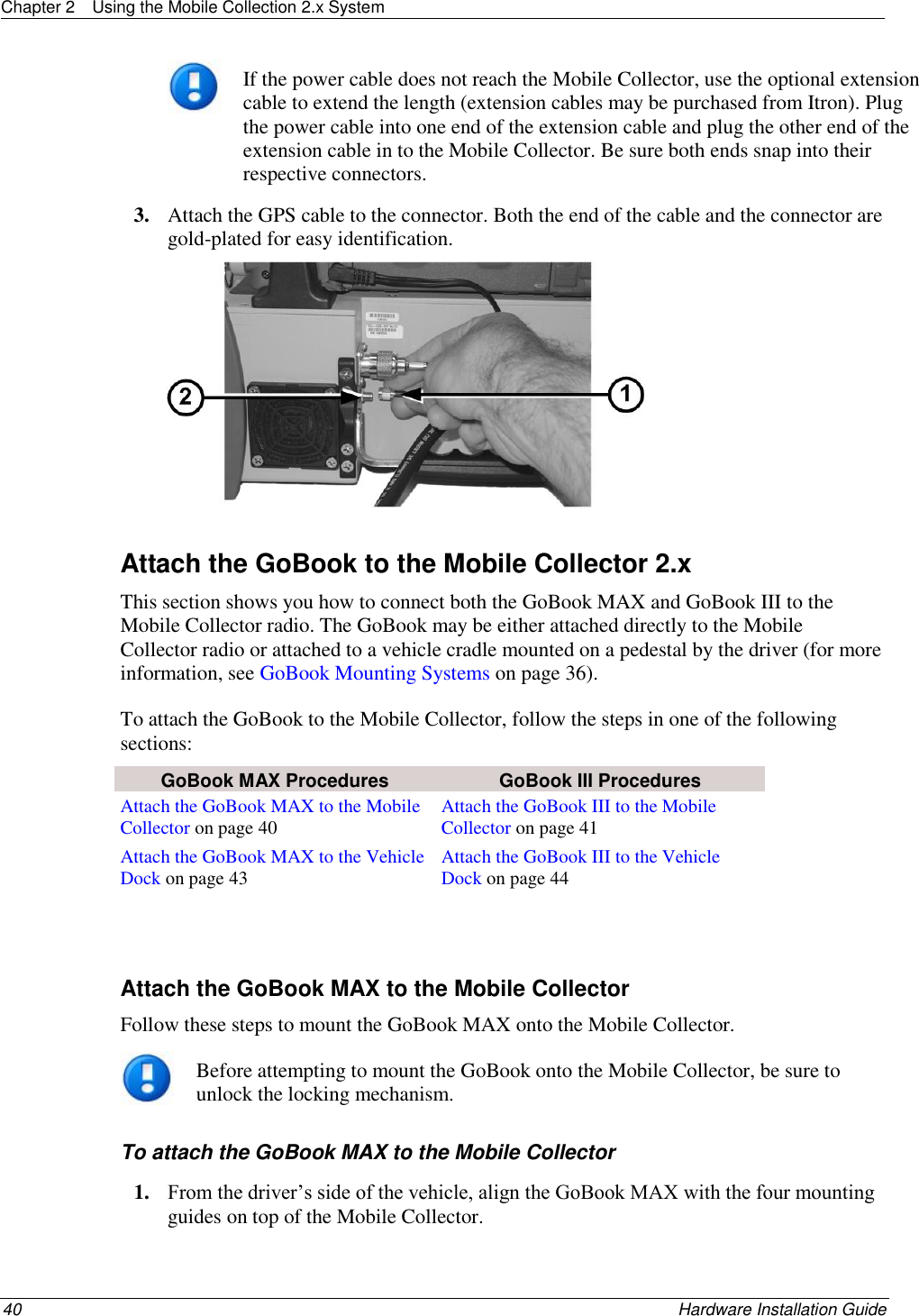
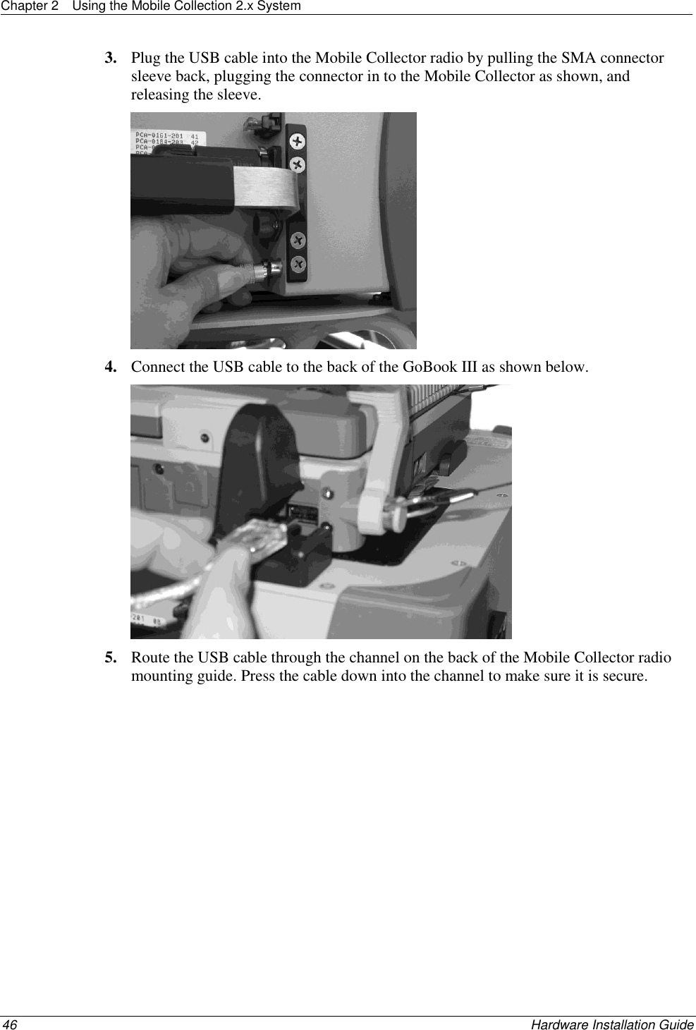
Contents
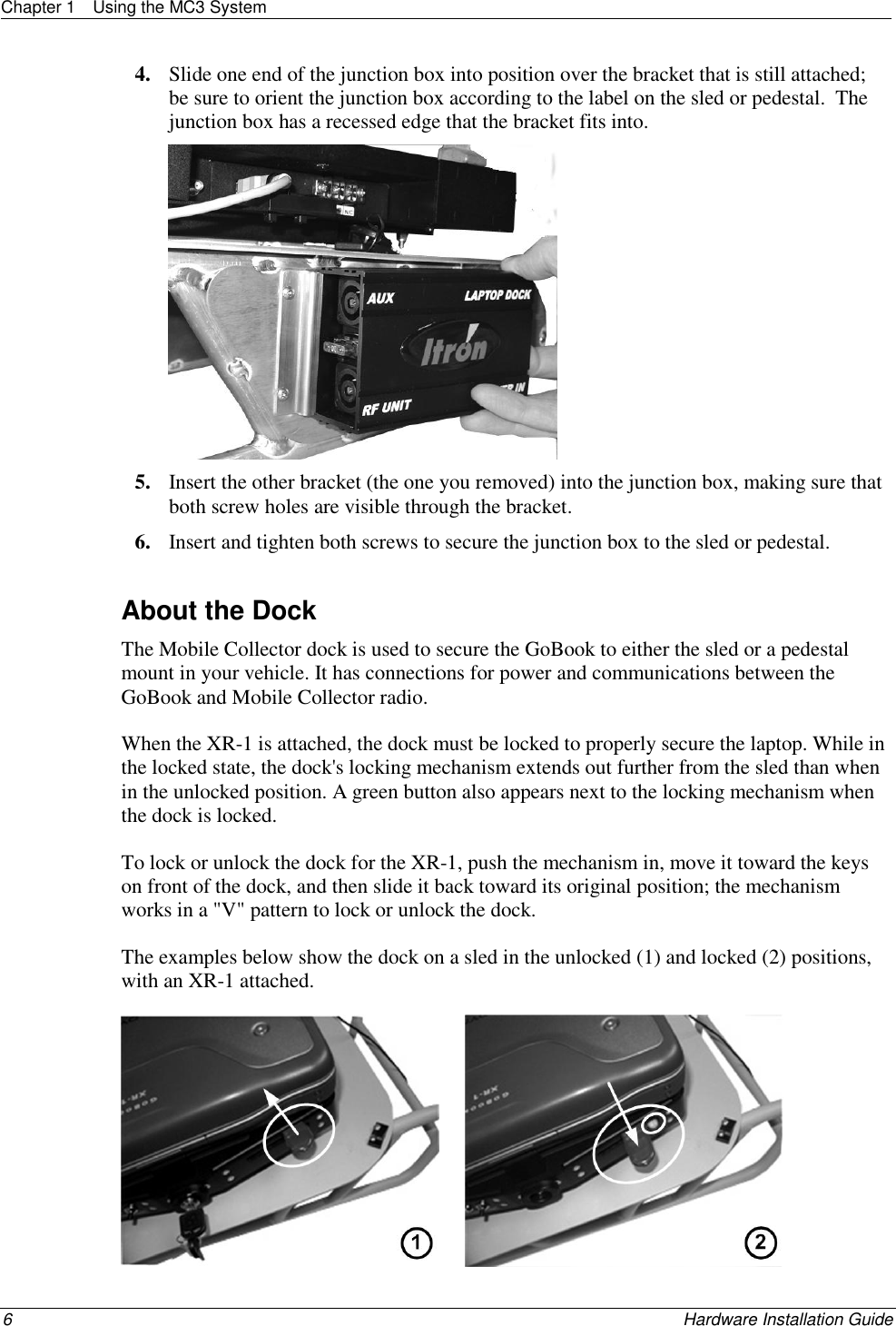
- 1. Users Manual Part 1
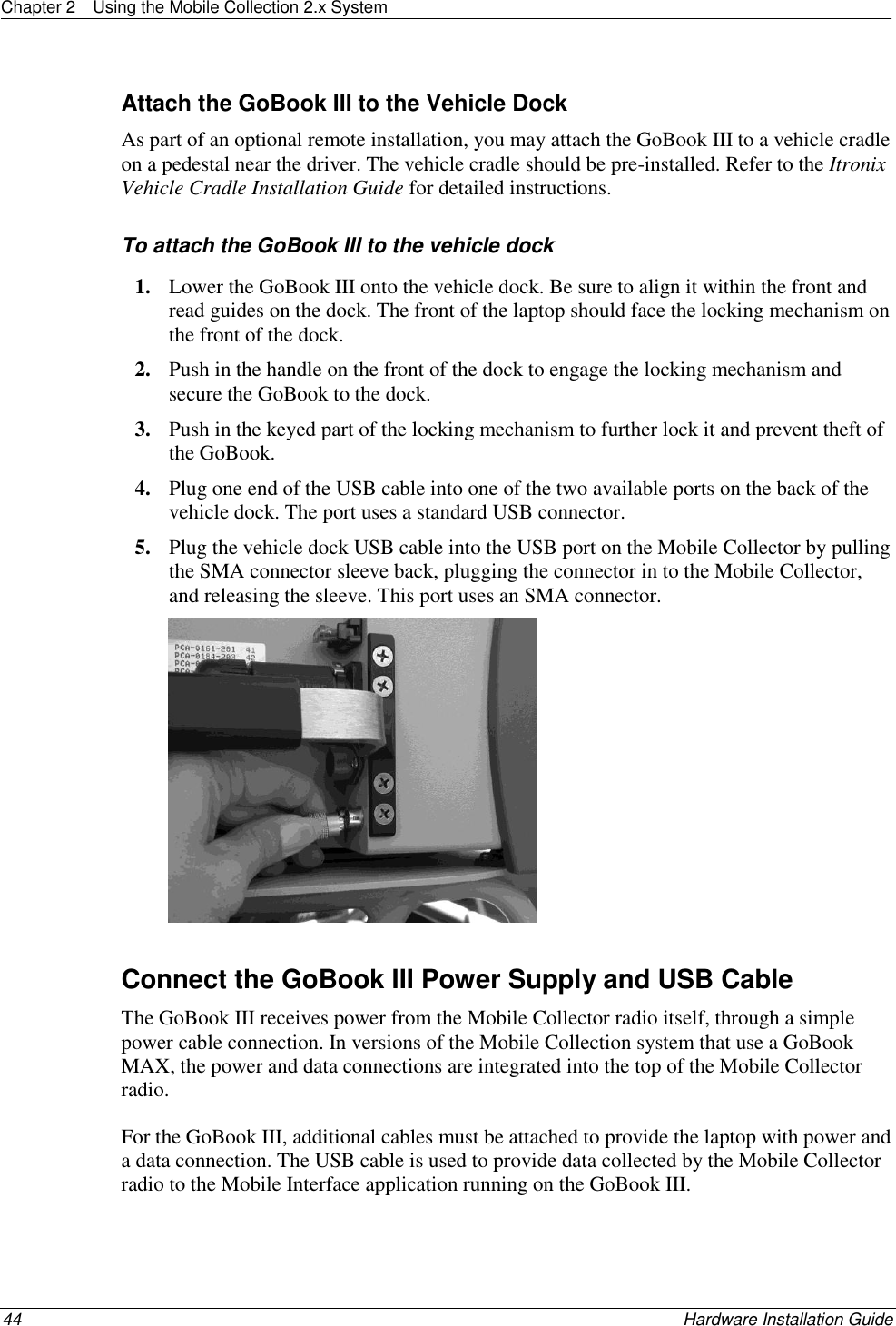
- 2. Users Manual Part 2
- 3. Final Users Manual
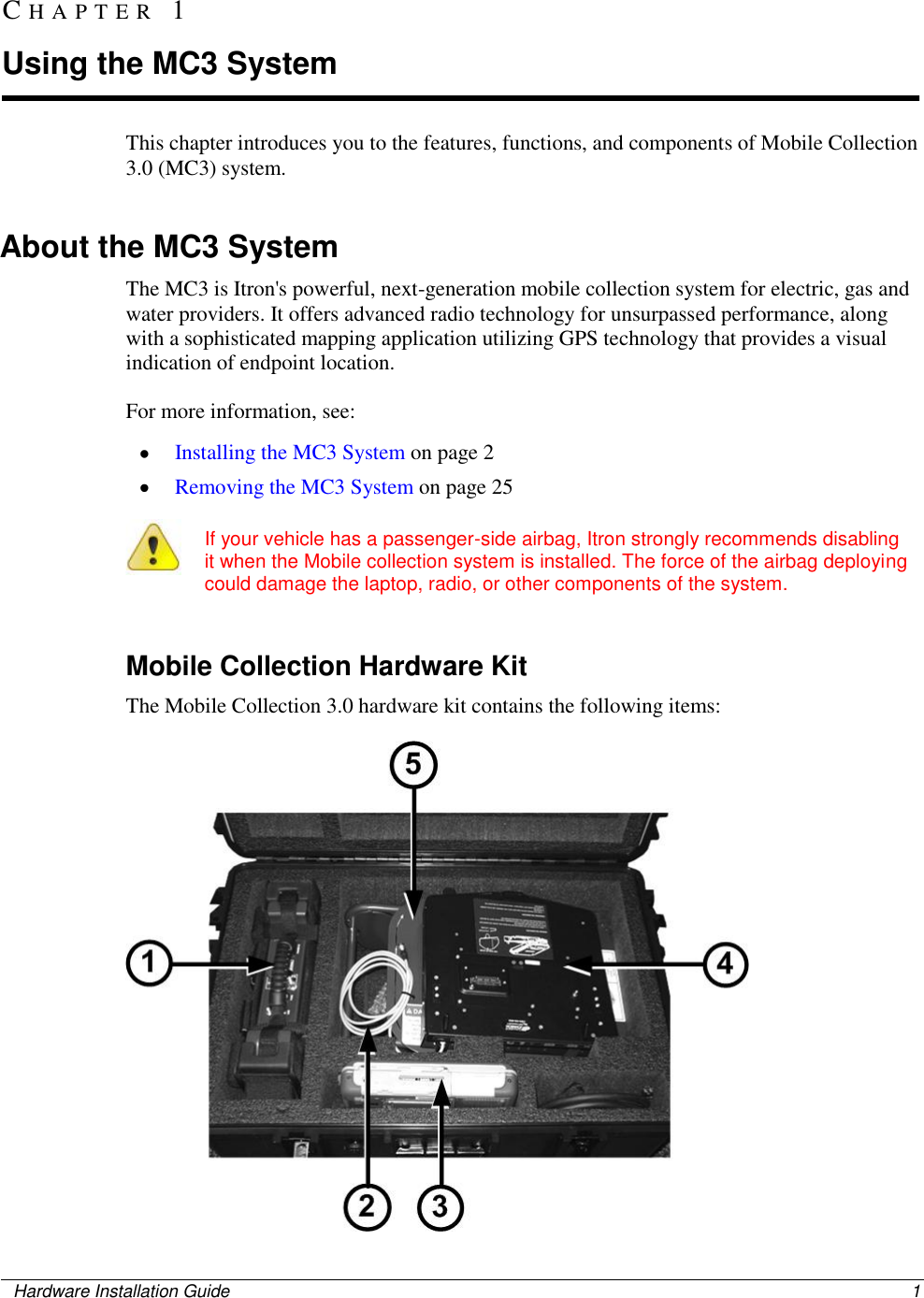
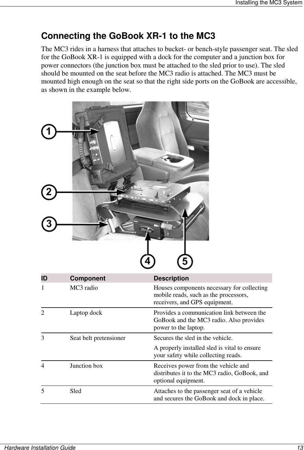
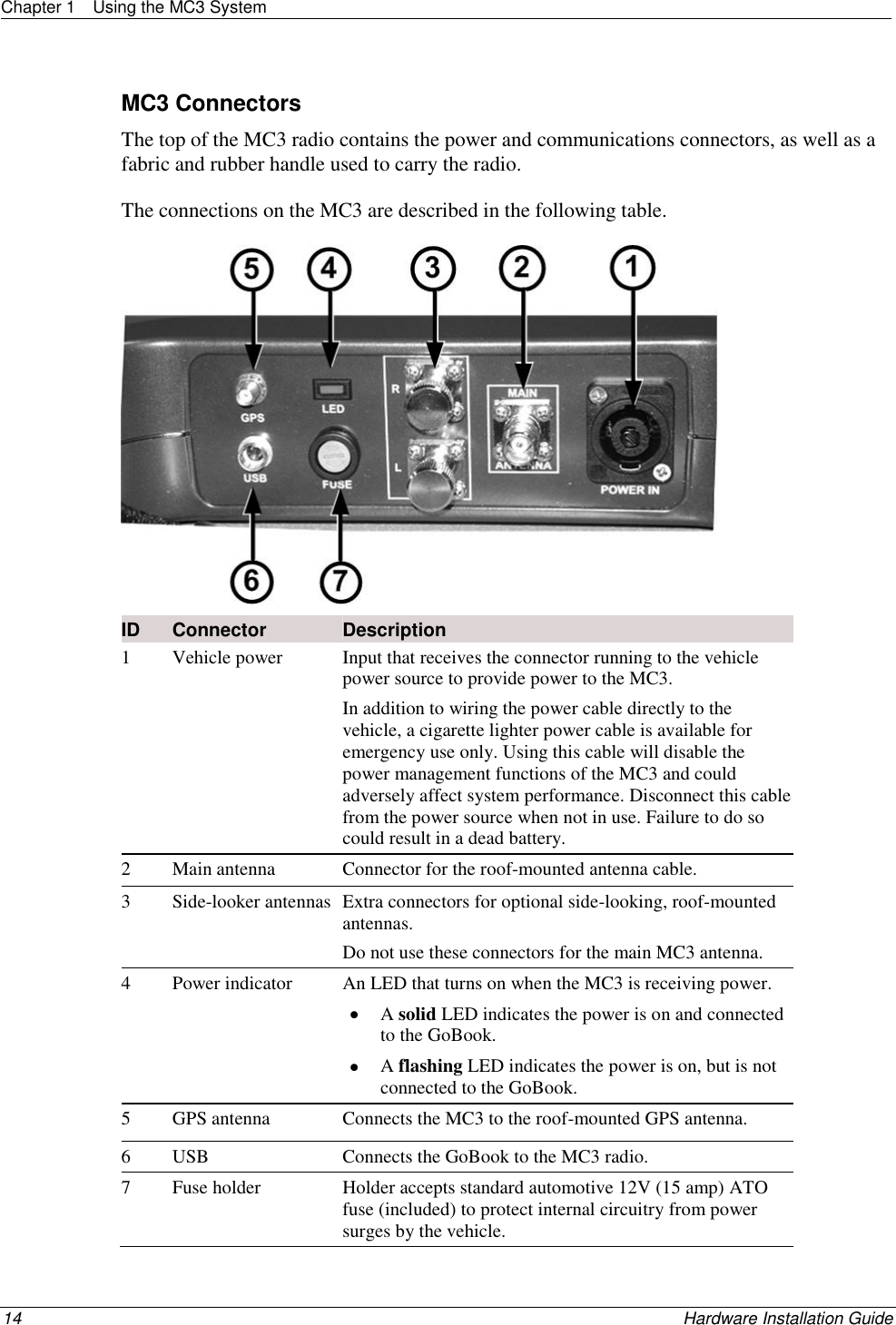
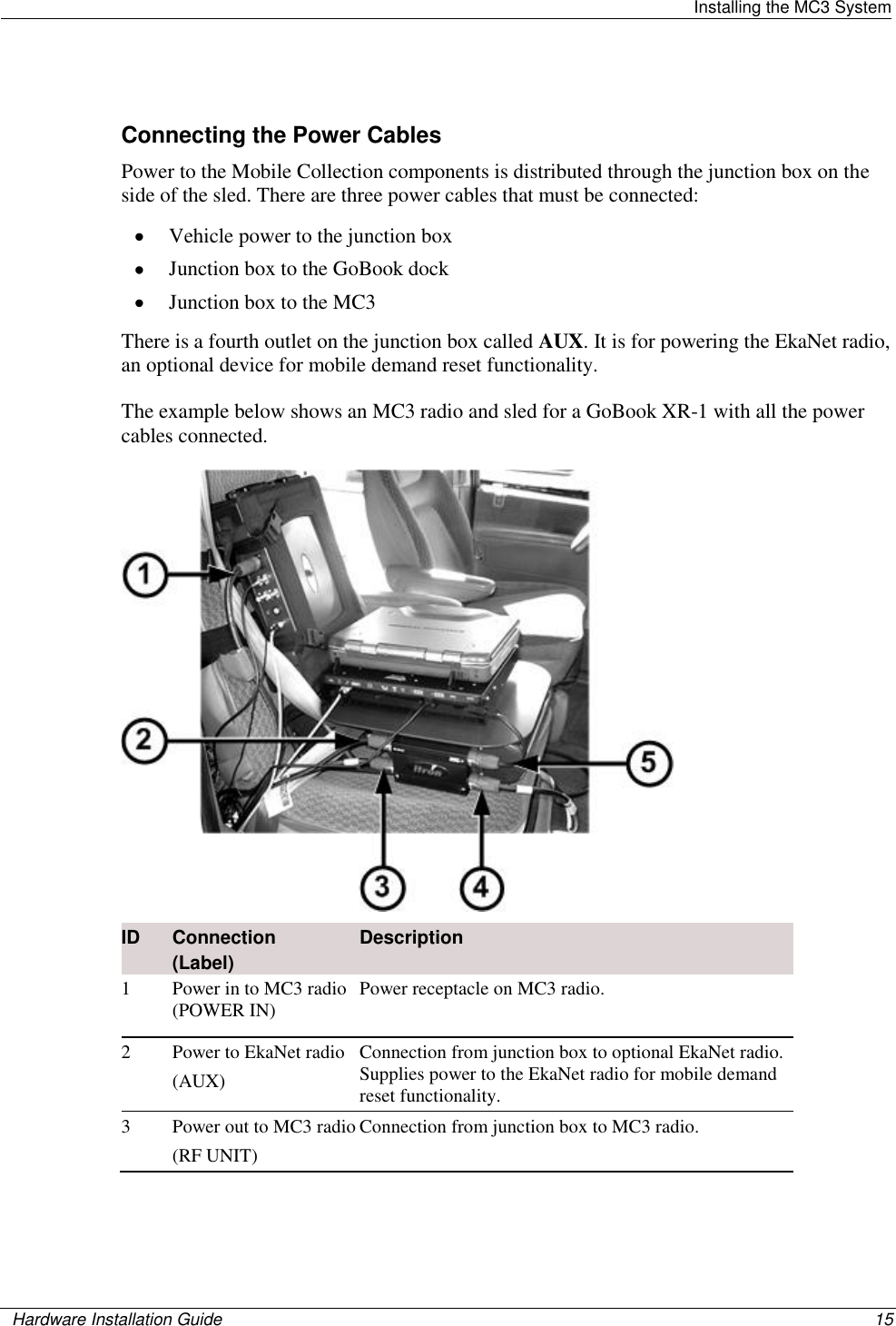
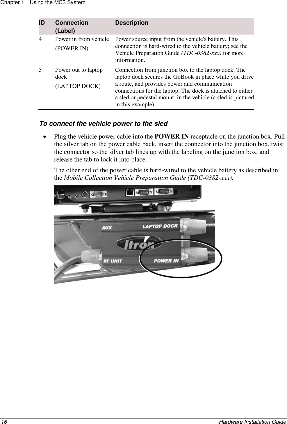
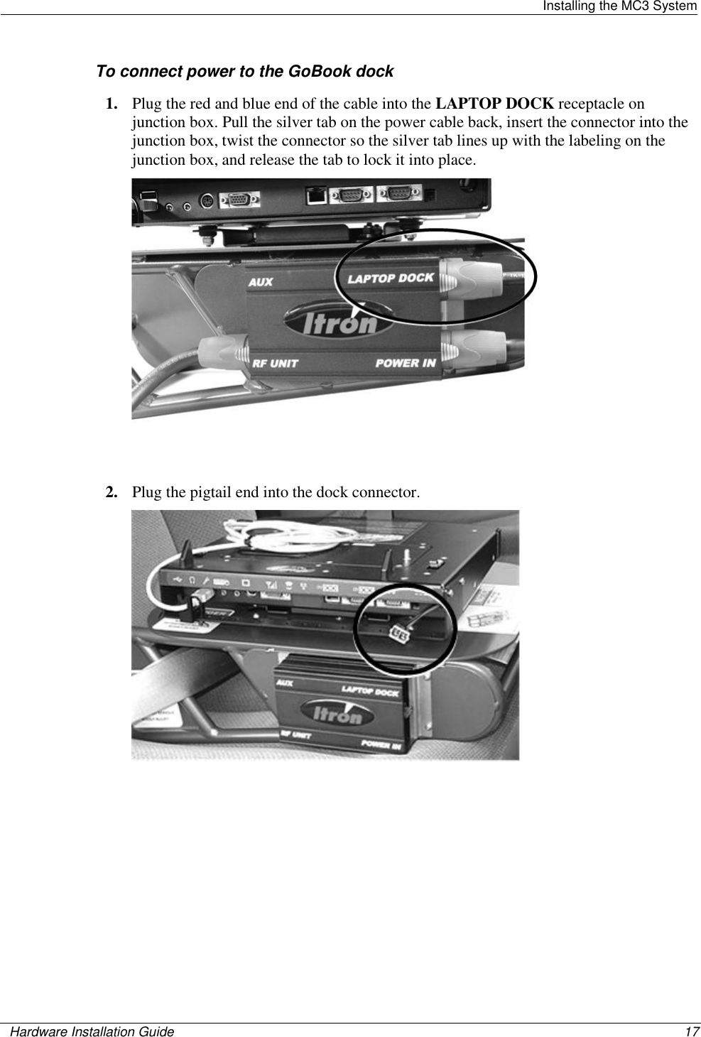
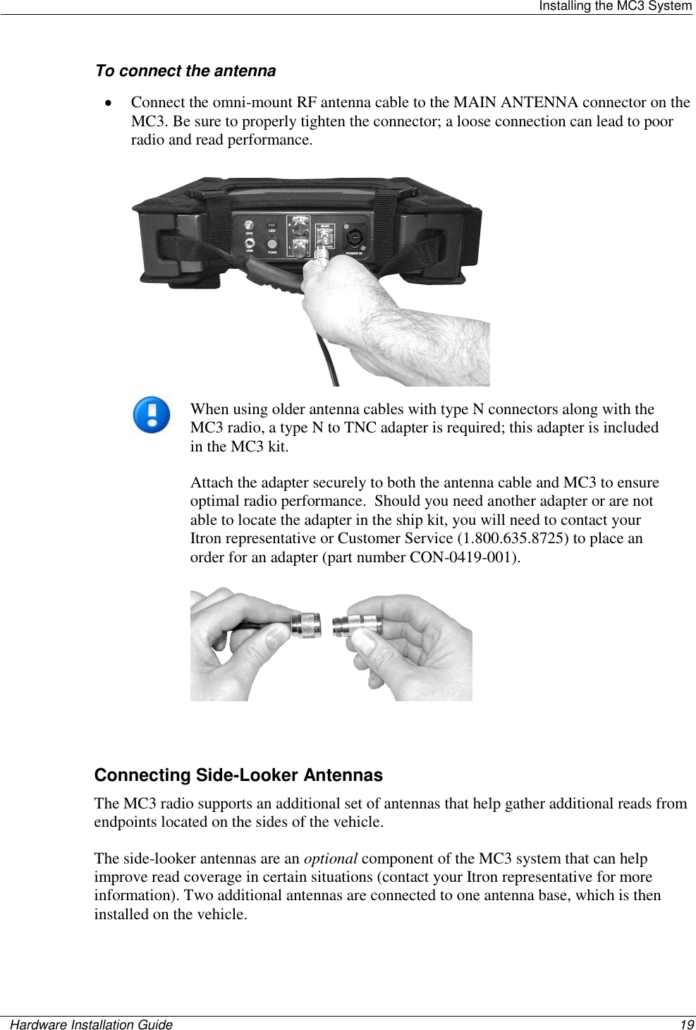
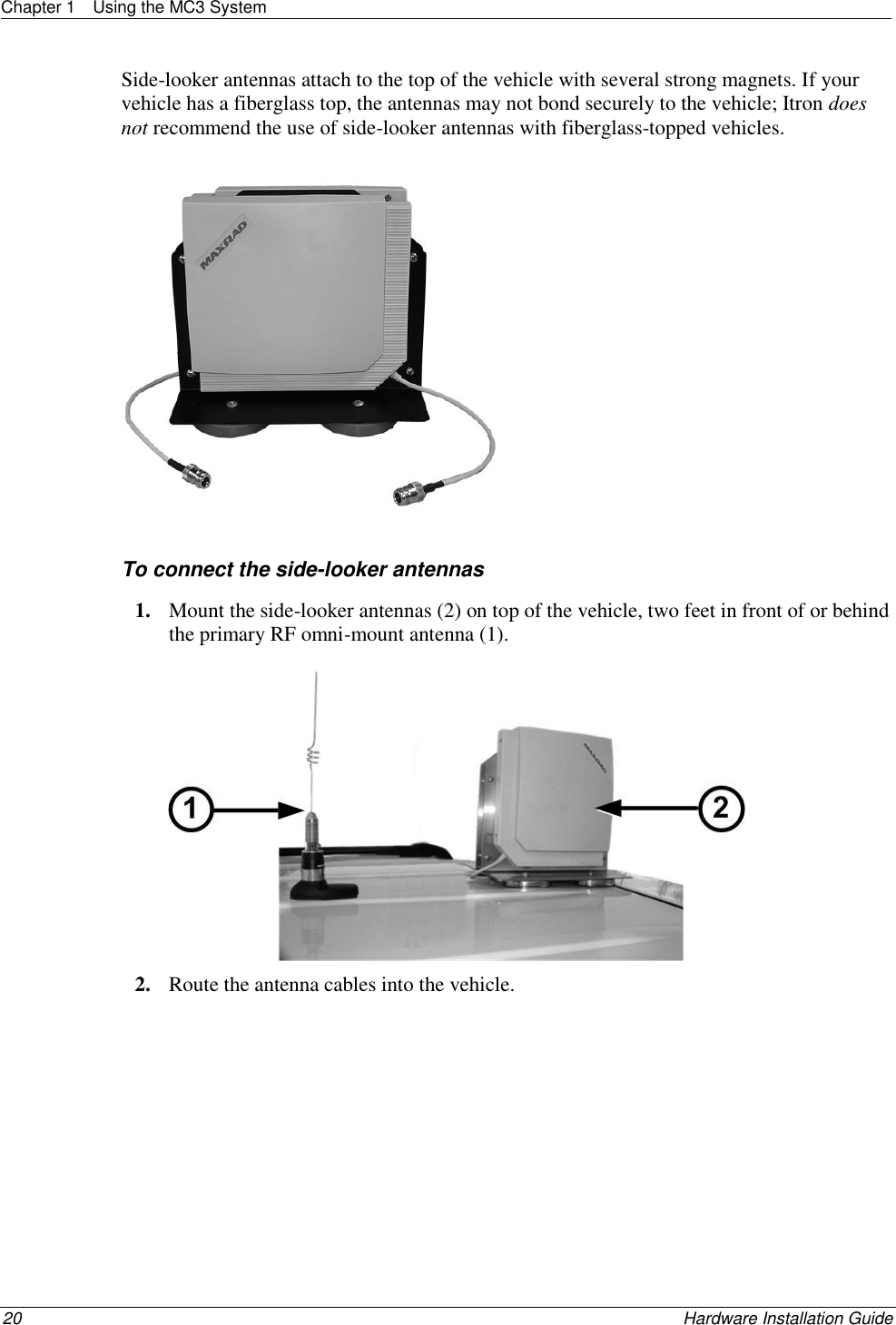
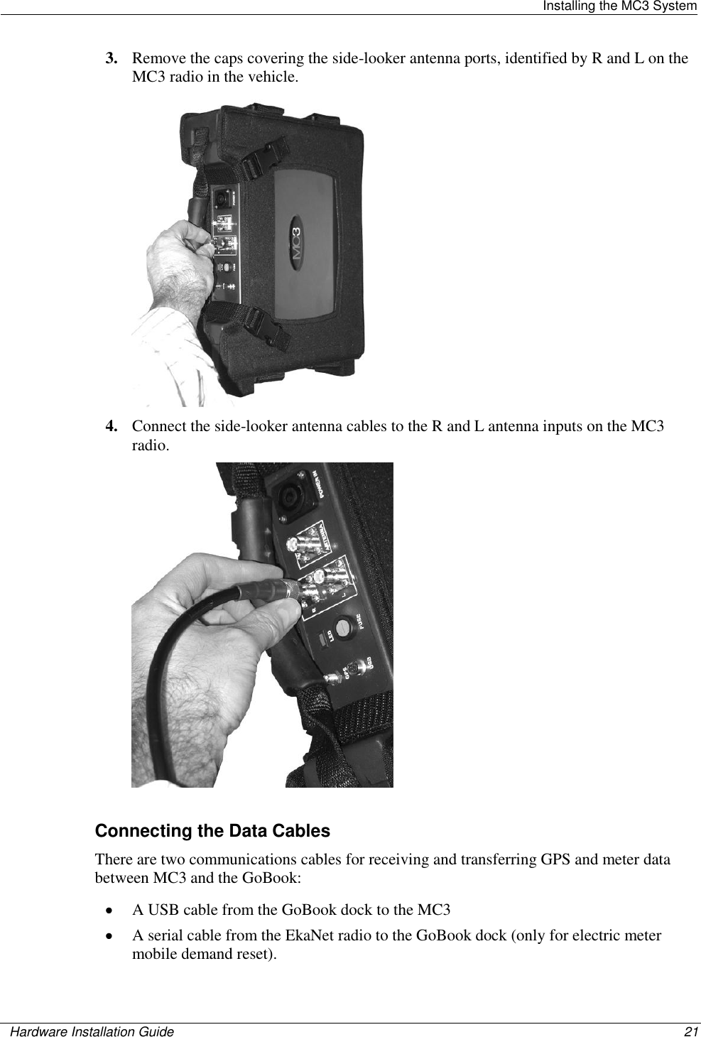
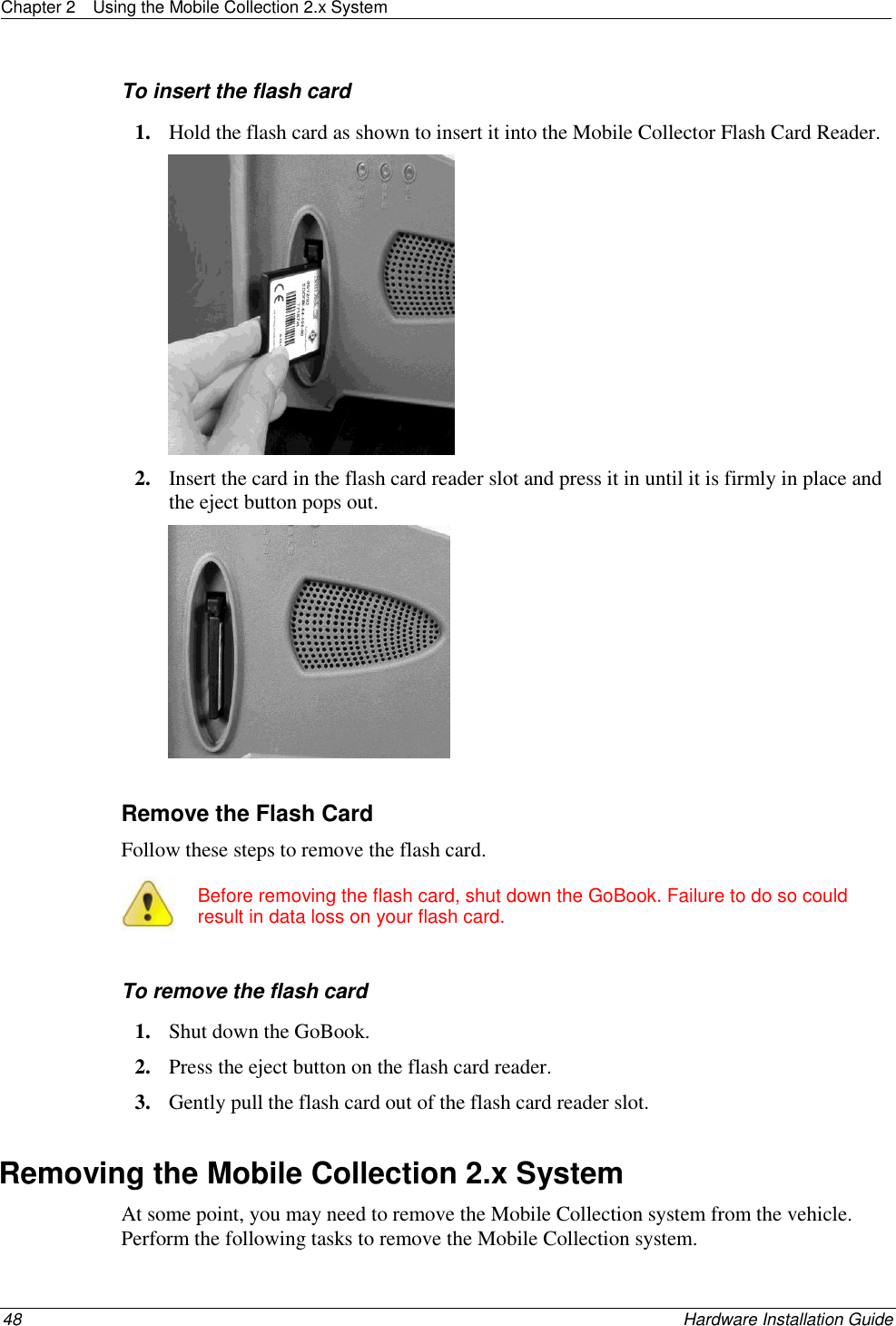
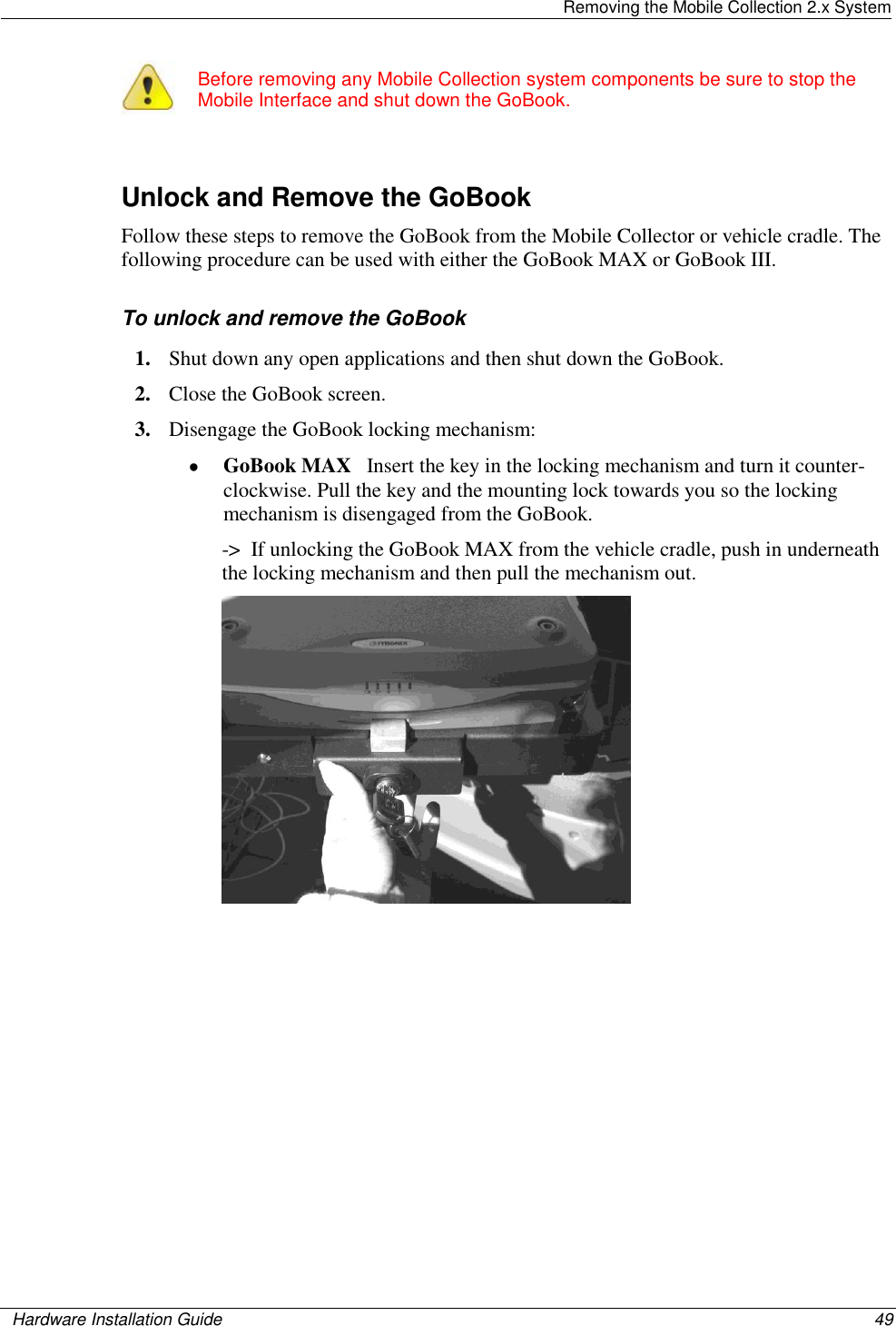
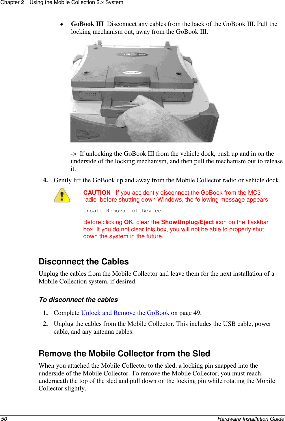
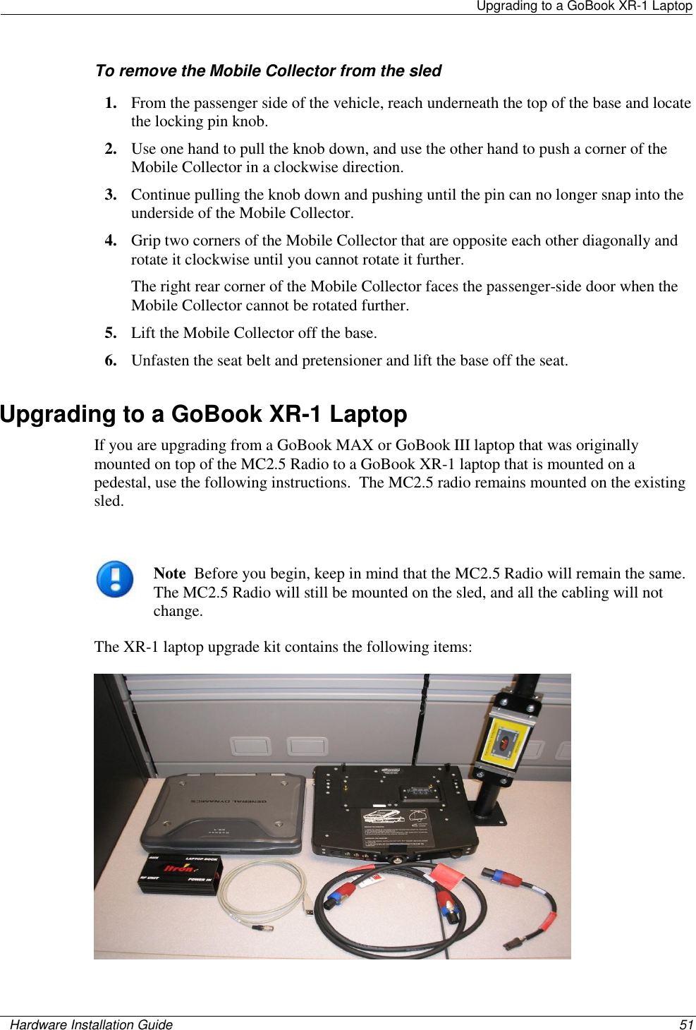
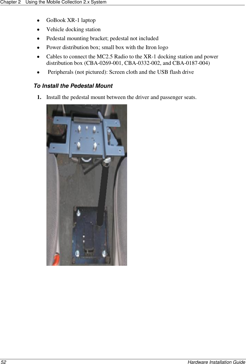
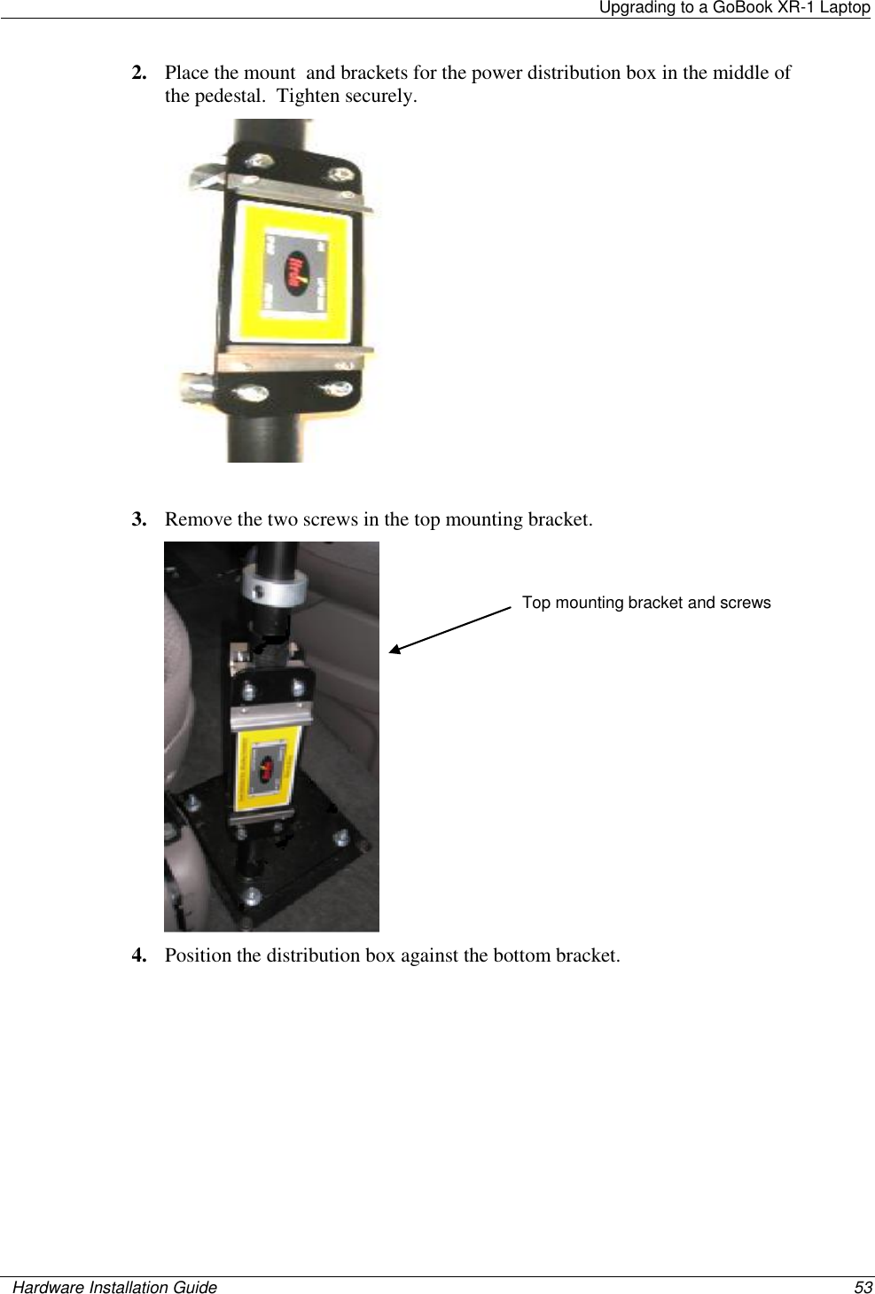
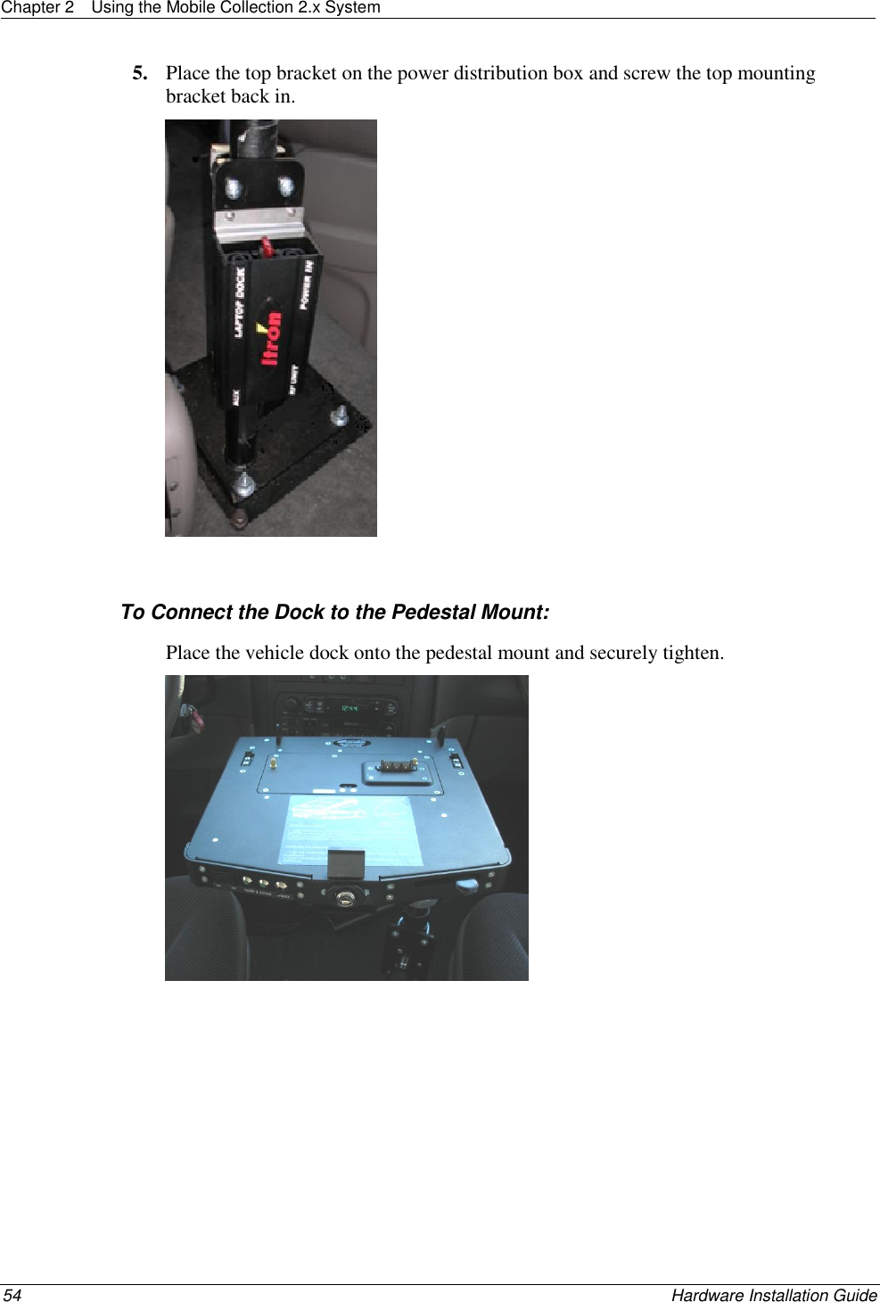
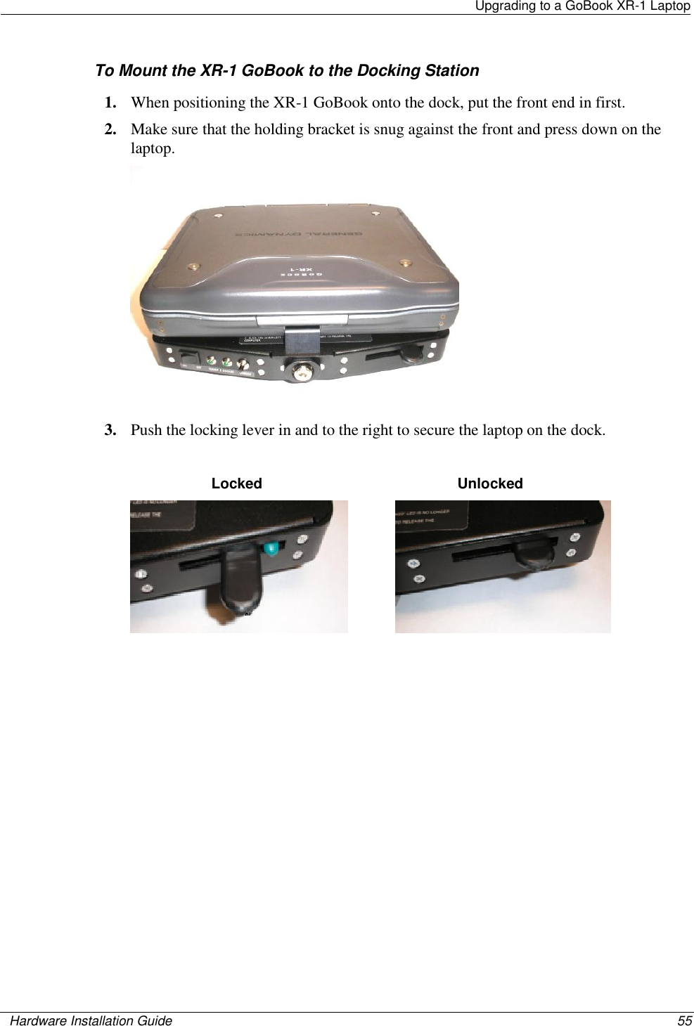
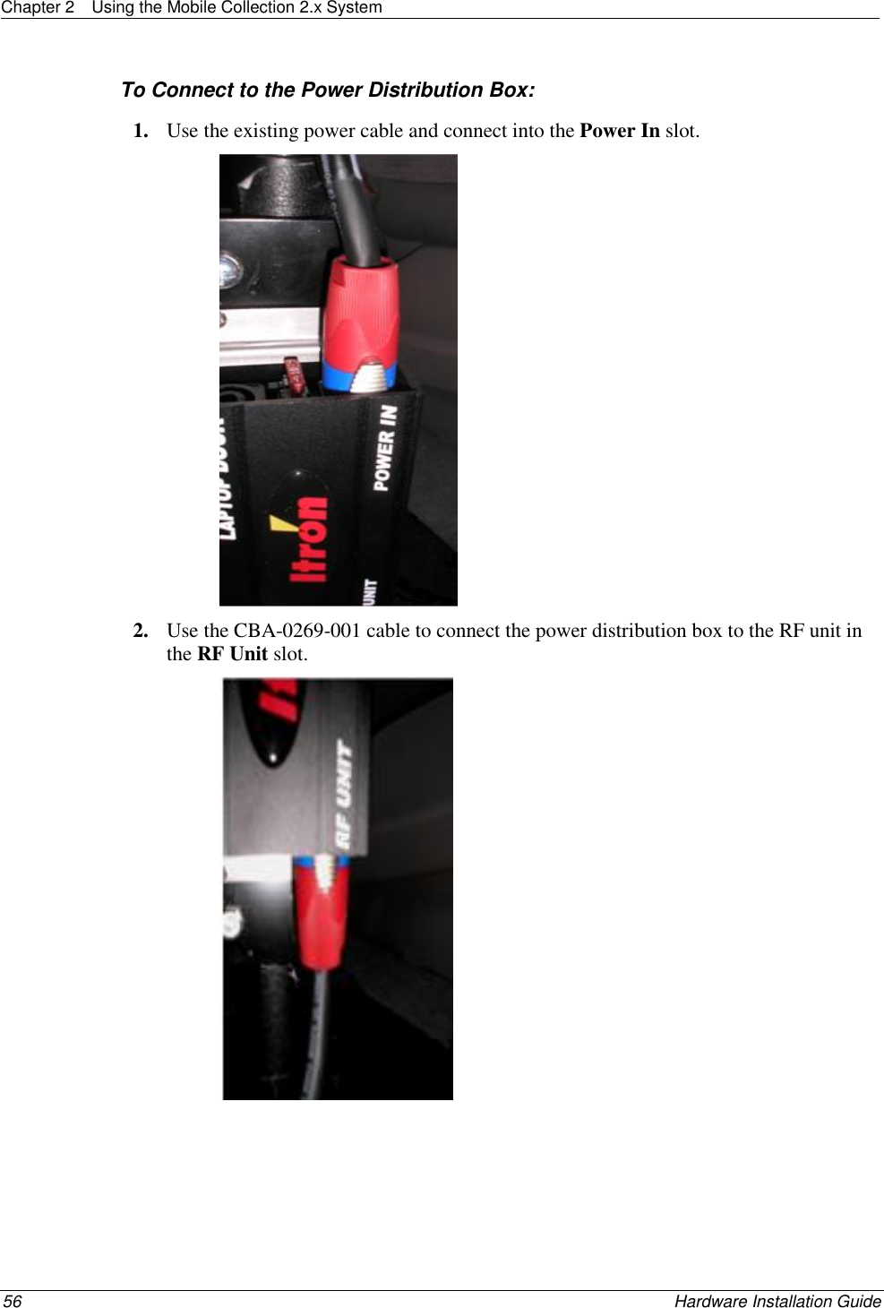
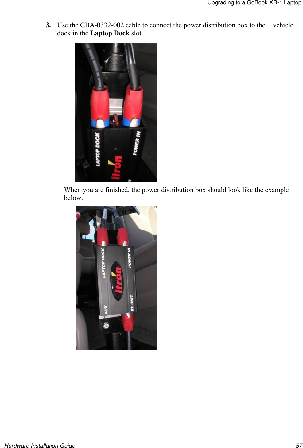
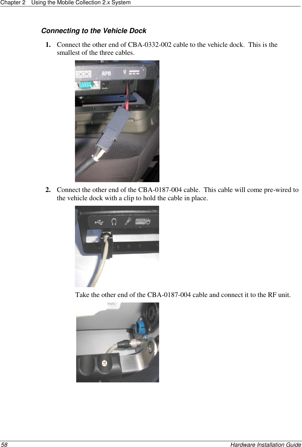
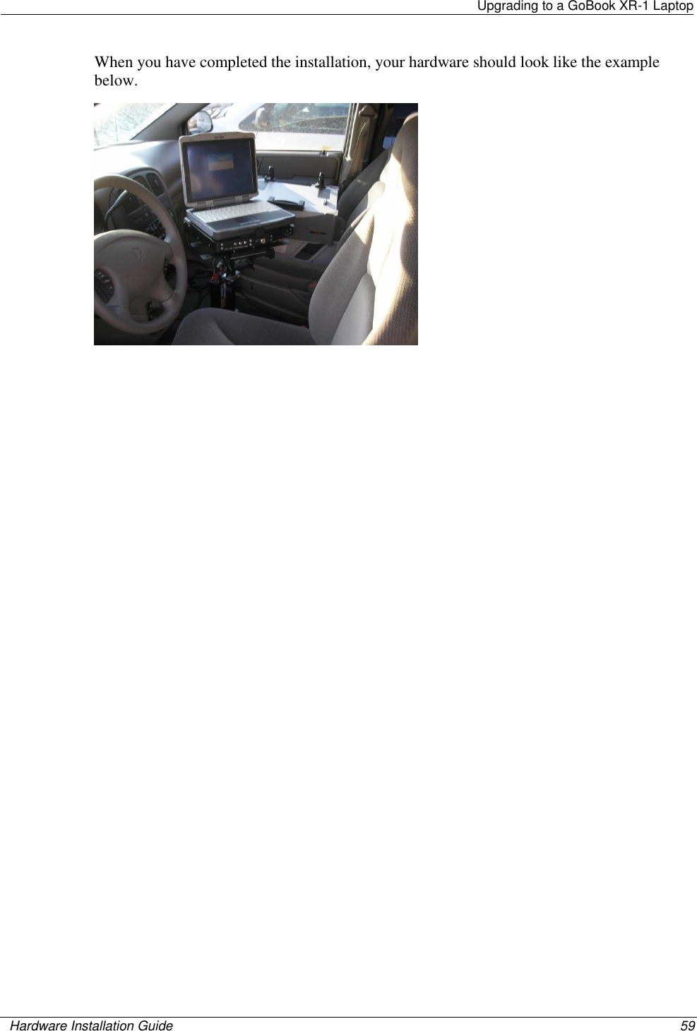
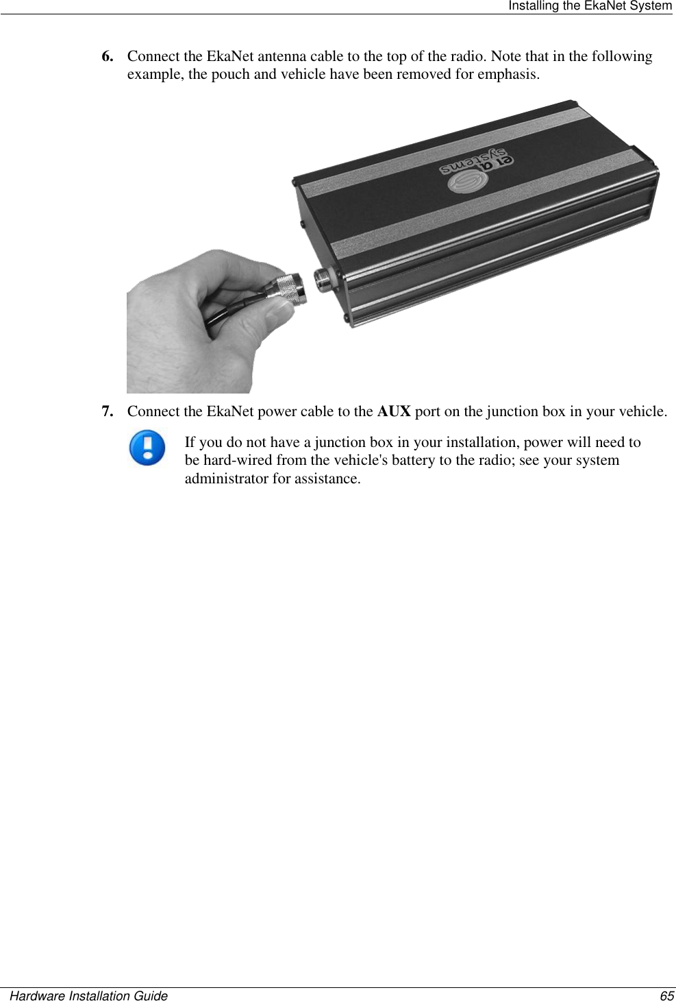
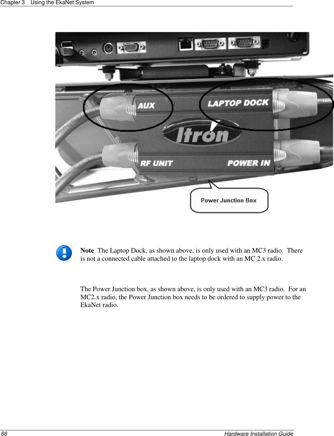
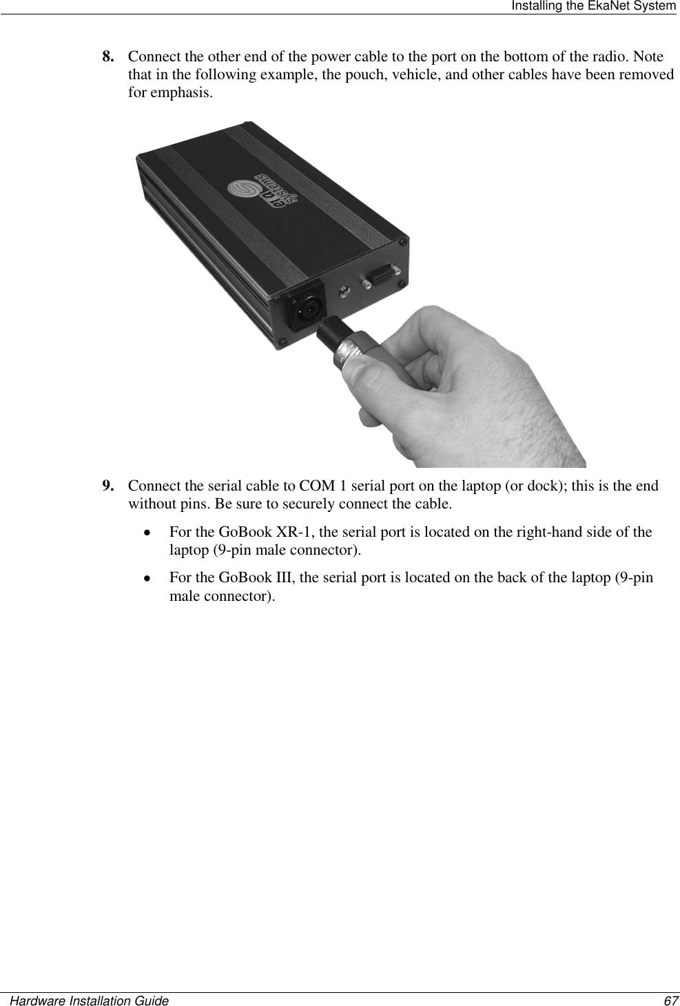
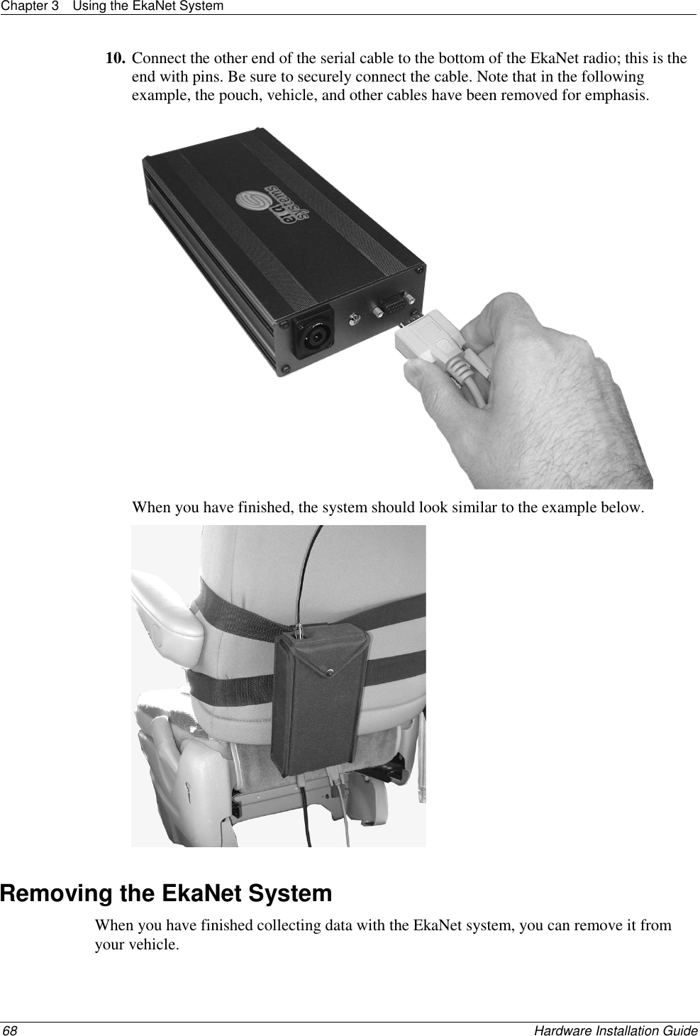
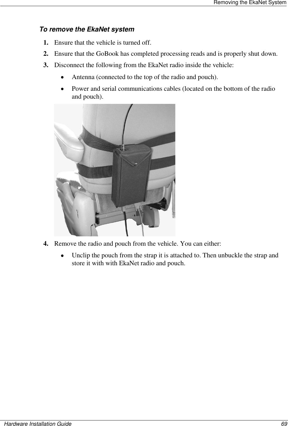
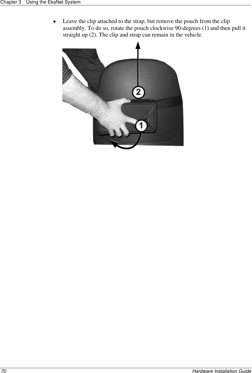
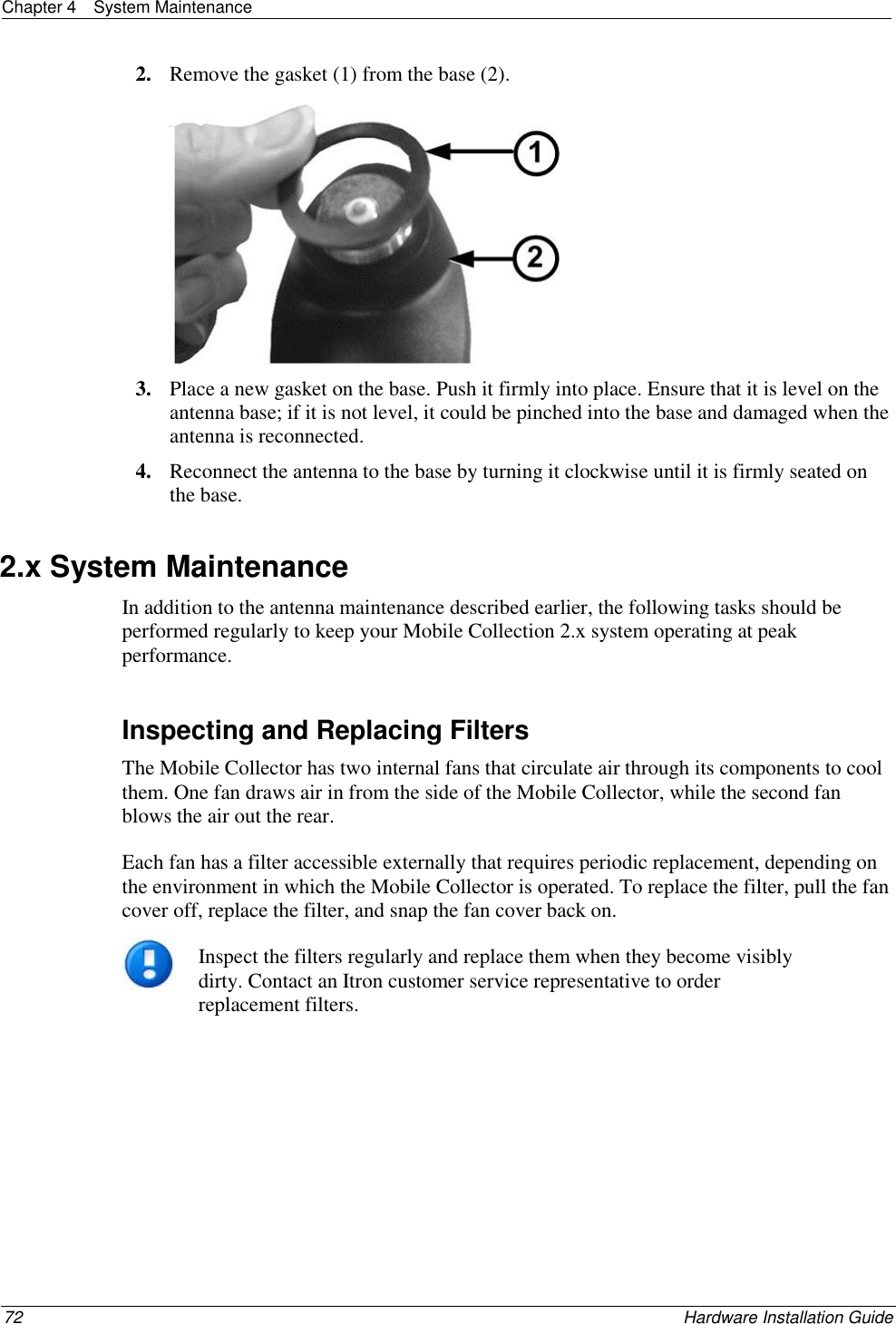
Final Users Manual