Itron DCU5310 Mobile collection device for utility metering User Manual Hardware Installation Guide
Itron, Inc. Mobile collection device for utility metering Hardware Installation Guide
Itron >
Contents
- 1. Users Manual Part 1
- 2. Users Manual Part 2
- 3. Final Users Manual
Users Manual Part 1

Mobile Collection
Hardware Installation Guide

Identification
Mobile Collection Hardware Installation Guide
04/28/2008 TDC-0770-001
Copyright
© 2007 - 2008 Itron, Inc. All rights reserved.
Trademark Notice
Itron is a registered trademark of Itron, Inc.
All other product names and logos in this documentation are used for identification purposes only and may be trademarks or registered trademarks of their respective companies.
Suggestions
If you have comments or suggestions on how we may improve this documentation, send them to TechnicalCommunicationsManager@itron.com
If you have questions or comments about the software or hardware product, contact Itron Technical Support:
Contact
• Internet: www.itron.com
• E-mail: support@itron.com
• Phone: 1 800 635 8725
Disclaimers
RF EXPOSURE
To comply with FCC requirements, maintain a separation distance of at least 40.0 centimetres between the antenna and all persons.
ELECTROMAGNETIC COMPATIBILITY
Use only approved accessories with this equipment. In general all cables must be high quality, shielded, correctly terminated, and normally restricted to 2 meters in length. The Mobile
Collector Lite employs special provisions to avoid radio interference and should not be altered or substituted.
Unapproved modifications or operation beyond or in conflict with these instructions for use, may void authorization by the authorities to operate the equipment.
WARNING! Do not visually monitor or physically adjust the Mobile Collection system while driving. While driving,
rely on the beeps produced when meter data is collected to indicate proper system operation. Visually monitoring
or adjusting the Mobile Collection system while driving will divert your attention from your safe driving
responsibilities. Attention to driving is your primary responsibility, along with following all the applicable driving
regulations.

Contents
Chapter 1 Using the MC3 System................................................................................1
About the MC3 System .......................................................................................................................1
Mobile Collection Hardware Kit.................................................................................................1
Installing the MC3 System...................................................................................................................2
About the Sled ..........................................................................................................................3
About the Seat Belt Pretensioner .............................................................................................4
Installing the Junction Box ........................................................................................................5
About the Dock .........................................................................................................................6
Attaching the GoBook XR-1 to the Dock ........................................................................6
Using the PCMCIA Flash Card Adapter ...................................................................................7
Mounting the MC3.....................................................................................................................9
Connecting the GoBook XR-1 to the MC3..............................................................................12
MC3 Connectors...........................................................................................................13
Connecting the Power Cables......................................................................................14
Connecting the Antenna...............................................................................................17
Connecting Side-Looker Antennas...............................................................................18
Connecting the Data Cables.........................................................................................20
Attaching Older GoBooks to the MC3.....................................................................................22
Attaching the GoBook III to the Vehicle Dock...............................................................22
Removing the MC3 System...............................................................................................................25
Disconnecting the Cables .......................................................................................................26
Chapter 2 Using the Mobile Collection 2.x System................................................27
About the Mobile Collection 2.x System............................................................................................27
Mobile Collector 2.x Radio - GoBook III .......................................................................27
Mobile Collector 2.x Radio - GoBook MAX...................................................................28
Flash Card Reader..................................................................................................................29
Compact Flash Cards .............................................................................................................29
LEDs .......................................................................................................................................29
Locking Mechanism ................................................................................................................30
Rear Connectors.....................................................................................................................30
Mobile Collector Sled..............................................................................................................32
GoBook Mounting Systems...............................................................................................................32
Direct Mounting Options .........................................................................................................32
Vehicle Dock / Pedestal Option ..............................................................................................33
Installing the Mobile Collection 2.x System.......................................................................................33
Attach the Mobile Collector 2.x to the Sled.............................................................................33
Connect the Antennas and Power Cables..............................................................................34
Attach the GoBook to the Mobile Collector 2.x.......................................................................35
Attach the GoBook MAX to the Mobile Collector..........................................................36
Attach the GoBook III to the Mobile Collector ..............................................................37
Attach the GoBook MAX to the Vehicle Dock...............................................................38
Attach the GoBook III to the Vehicle Dock ...................................................................39
Connect the GoBook III Power Supply and USB Cable .........................................................40
Using the Flash Card in Mobile Collector 2.x Systems...........................................................42
Insert the Flash Card ....................................................................................................42
Hardware Installation Guide iii

Contents
Remove the Flash Card................................................................................................43
Removing the Mobile Collection 2.x System.....................................................................................44
Unlock and Remove the GoBook............................................................................................44
Disconnect the Cables............................................................................................................45
Remove the Mobile Collector from the Sled ...........................................................................45
Chapter 3 Using the EkaNet System .......................................................................47
EkaNet System for Mobile Demand Reset........................................................................................47
EkaNet Compatibility.........................................................................................................................47
About the EkaNet Components.........................................................................................................48
Installing the EkaNet System ............................................................................................................49
Removing the EkaNet System ..........................................................................................................54
Chapter 4 System Maintenance...............................................................................57
RF Antenna Maintenance..................................................................................................................57
Cleaning..................................................................................................................................57
Replacing Gaskets..................................................................................................................57
2.x System Maintenance...................................................................................................................58
Inspecting and Replacing Filters.............................................................................................58
Service Bulletins................................................................................................................................59
Mobile Collection 2.5 / GoBook III Power Plug Issue .............................................................59
Mobile Collector 2.x Power Adapter .......................................................................................59
iv Hardware Installation Guide
CHAPTER 1
Using the MC3 System
This chapter introduces you to the features, functions, and components of Mobile Collection
3.0 (MC3) system.
About the MC3 System
The MC3 is Itron's powerful, next-generation mobile collection system for electric, gas and
water providers. It offers advanced radio technology for unsurpassed performance, along
with a sophisticated mapping application utilizing GPS technology that provides a visual
indication of endpoint location.
For more information, see:
• Installing the MC3 System on page 2
• Removing the MC3 System on page 25
If your vehicle has a passenger-side airbag, Itron strongly recommends disabling
it when the Mobile collection system is installed. The force of the airbag deploying
could damage the laptop, radio, or other components of the system.
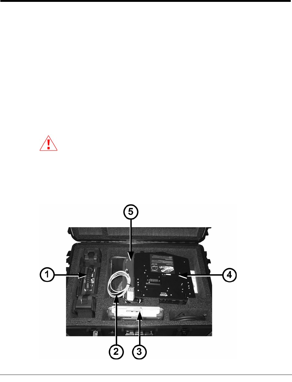
Mobile Collection Hardware Kit
The Mobile Collection 3.0 hardware kit contains the following items:
Hardware Installation Guide 1

Chapter 1 Using the MC3 System
ID Item Description
1 MC3 radio Includes a mounting harness and straps for installing
the system in your vehicle.
2 USB cable
Comes attached to the dock and attaches to the
GoBook. Provides communication between GoBook
and MC3 radio.
3 GoBook XR-1
Runs the Mobile Collection software to collect reads.
The MC3 radio is also compatible with the GoBook III
laptop.
4 GoBook dock
The GoBook, power cables, and communication cables
attach to the dock.
5 Sled Installs in the vehicle's passenger seat with the attached
seat belt pretensioner. Sleds are available for both the
XR-1 and GoBook III.
Cables Connects the MC3 and GoBook dock to the junction
box.
Power junction
box Attaches to the sled or to a pedestal mount. Provides
power to the GoBook, MC3 radio, and optional
equipment.
The junction box must be installed prior to first use.
See Installing the Junction Box on page 5 for more
information.
Omni-mount
antenna Attaches to the top of the vehicle and receives endpoint
transmissions.
Not
Pictured
Type N to TNC
adapter Connects older antennas to the MC3 radio.
This adapter is only needed if you are using an MC3
radio with an older omni-mount antenna (such as one
from a v2.5 system) that is already installed on your
vehicle.
The Itronix documentation refers to the laptop receptacle as a cradle; Itron uses
the term dock to identify this piece of equipment. The term dock is used repeatedly
throughout this manual; however, dock and cradle are interchangeable.
Installing the MC3 System
This chapter guides you through the installation of the Mobile Collector radio (MC3) and
GoBook XR-1 laptop computer.
Before installing these Mobile Collection system components, the procedures in the Mobile
Collector Vehicle Preparation Guide and Mobile Collector Sled and Pretensioner
Installation Guide must be completed.
WARNING! Install the Mobile Collection system in the vehicle as
described in this document and those listed above. Failure to do so could
lead to injury or death from unsecured components during a collision.
2 Hardware Installation Guide
Installing the MC3 System
About the Sled
The Mobile Collector sled is used to securely fasten the GoBook in the vehicle. It is placed
on the passenger seat and secured with a seat belt and pretensioner.
Watch the Mobile Collector Safety Video and read the Mobile Collector Sled
and Pretensioner Installation Guide (TDC-0708-xxx) to learn how to correctly
install the sled in your vehicle. These materials are located in a plastic sleeve
on the underside of the sled.
The sled has the GoBook dock attached to it, which serves as a locking base and also
provides power and communications to the laptop.
A power junction box ships in the Mobile Collector kit and needs to be attached to the sled.
When attached, the junction box on the sled should be facing passenger side door of the
vehicle (the junction box is attached in the example below).
Install the sled on the passenger seat before mounting the MC3 radio. The sled must be
installed with the seat belt pretensioner; see About the Seat Belt Pretensioner on page 4 for
more information.
The sled components are shown below.
ID Item Description
1 Mobile Collector
sled Attaches to the vehicle passenger seat with the seat belt
and pretensioner system.
2 Junction box
Provides power to the various Mobile Collection
components. The junction box must be attached prior to
first use.
3 GoBook dock
Attaches to the GoBook and provides a secure base for
the laptop while in the vehicle. Docks are available for
use with both XR-1 and GoBook III models.
Hardware Installation Guide 3
Chapter 1 Using the MC3 System
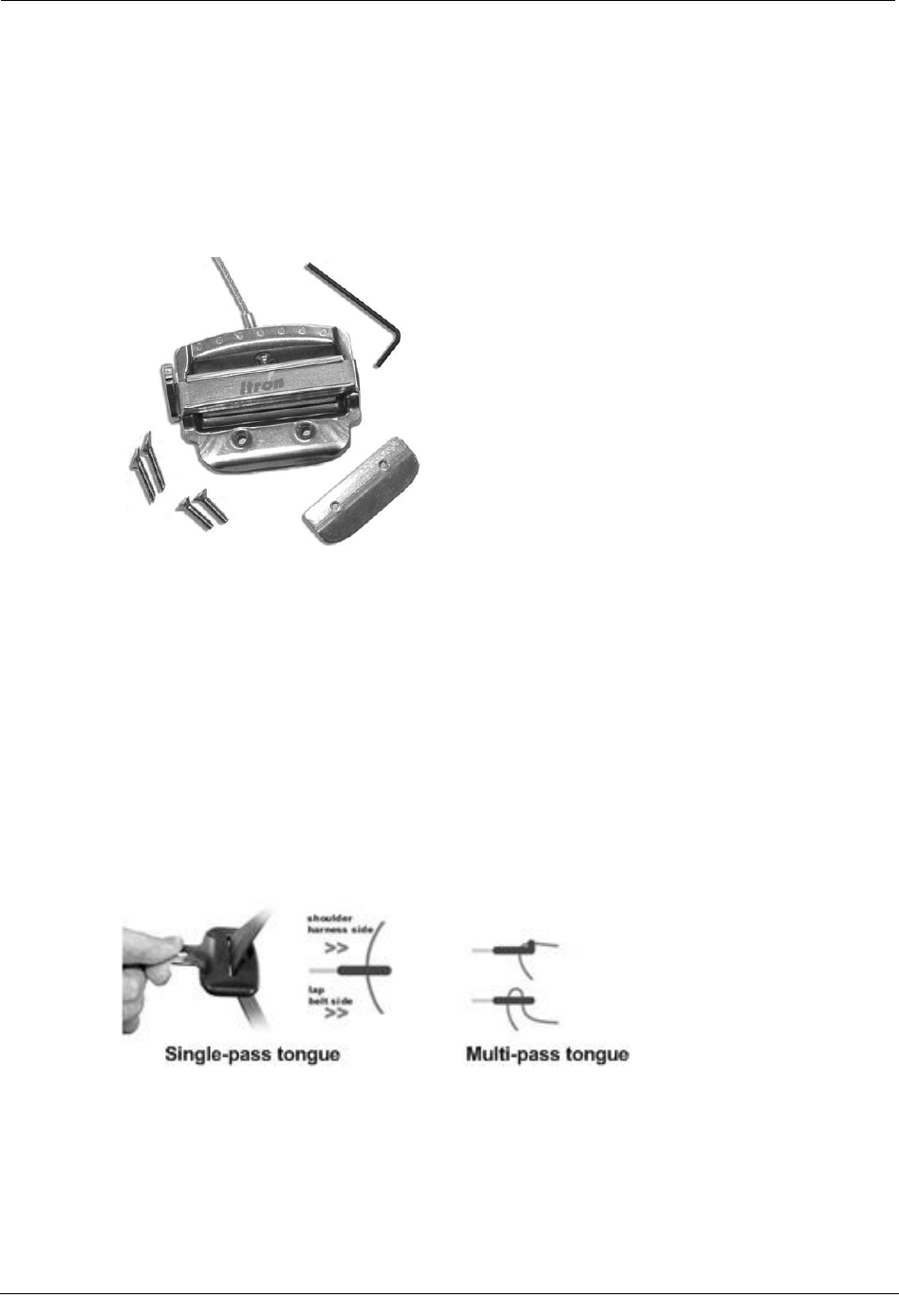
About the Seat Belt Pretensioner
The seat belt pretensioner makes the modern three-point safety harness in your vehicle
function similarly to an old-fashioned lap seat belt. By using the pretensioner mechanism to
cinch the mounting hardware very firmly into the junction of the seat back and the seat pad,
the pretensioner and radio mount restricts potentially hazardous equipment movement
during impact.
Modern three-point harnesses are designed to be forgiving to occupants to lessen injury. By
preventing the pay-out of seat belt webbing designed to protect people and instead using the
pretensioner to immobilize equipment, a higher degree of protection is provided in the event
of a collision.
Through standardized crash testing of the Mobile Collection system, Itron has determined
that preventing extensive rotation of the Mobile Collection equipment in a driver's side
impact reduced the stress on mechanical systems to acceptable levels. Decreasing the
amount of equipment rotation towards the driver prevents the fasteners holding the GoBook
and its dock to the sled from separating in a crash.
The seat belt pretensioner can be used in vehicles equipped with single-pass and multiple-
pass seat-belt tongues.
To install the seat belt pretensioner
• Follow the procedures in the Mobile Collector Sled and Pretensioner Installation
Guide (TDC-0708-xxx). A DVD showing the installation is also included with your
kit. These materials are located in a plastic sleeve on the underside of the sled.
4 Hardware Installation Guide
Installing the MC3 System
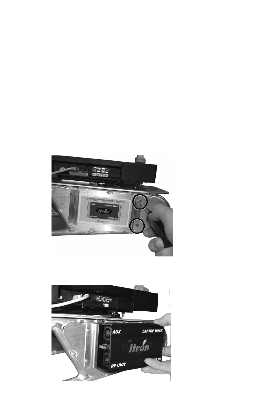
Installing the Junction Box
The junction box takes power from the vehicle and distributes it to the MC3 radio, GoBook,
and an optional EkaNet radio (when installed).
Before you can install the MC3 system for the first time, the junction box must be installed
on either the sled or a pedestal mount.
Once installed, the junction box should remain attached to the sled or pedestal.
To install the junction box
1. Remove the junction box from the MC3 kit.
2. Locate the sled or pedestal mount on which the junction box will be installed. In the
following example, a sled is used.
3. Using a Phillips screwdriver, remove the two screws holding the junction box bracket
in place.
4. Slide one end of the junction box into position over the bracket that is still attached;
be sure to orient the junction box according to the label on the sled or pedestal. The
junction box has a recessed edge that the bracket fits into.
Hardware Installation Guide 5
Chapter 1 Using the MC3 System
5. Insert the other bracket (the one you removed) into the junction box, making sure that
both screw holes are visible through the bracket.
6. Insert and tighten both screws to secure the junction box to the sled or pedestal.
About the Dock
The Mobile Collector dock is used to secure the GoBook to either the sled or a pedestal
mount in your vehicle. It has connections for power and communications between the
GoBook and Mobile Collector radio.
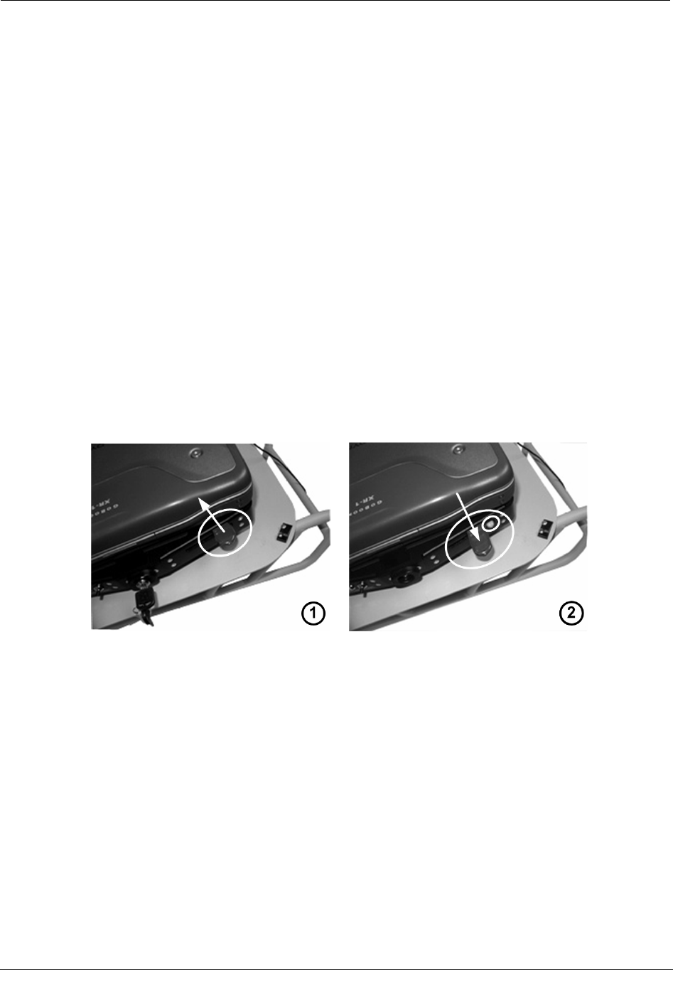
When the XR-1 is attached, the dock must be locked to properly secure the laptop. While in
the locked state, the dock's locking mechanism extends out further from the sled than when
in the unlocked position. A green button also appears next to the locking mechanism when
the dock is locked.
To lock or unlock the dock for the XR-1, push the mechanism in, move it toward the keys
on front of the dock, and then slide it back toward its original position; the mechanism
works in a "V" pattern to lock or unlock the dock.
The examples below show the dock on a sled in the unlocked (1) and locked (2) positions,
with an XR-1 attached.
A dock is also available for use with the GoBook III laptop; see Attaching the GoBook III
to the Vehicle Dock on page 22 for more information.
Attaching the GoBook XR-1 to the Dock
1. Make sure the dock is in the unlocked position.
6 Hardware Installation Guide
Installing the MC3 System
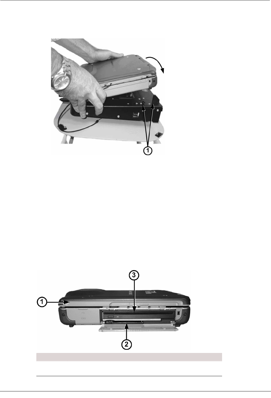
2. Angle the front of the GoBook down, toward the front of the dock (where the key and
locking mechanism are). Notice the connectors and guide posts (1) near the back of
the sled base. These help ensure proper placement of the GoBook.
3. Push the back of the laptop down on to the connectors.
4. When the laptop is in place, engage the dock locking mechanism to secure the
connectors to the laptop and prevent it from moving.
5. Push the keyed mechanism in on the front of the dock to further secure the GoBook to
the dock. This helps prevent the GoBook from being stolen. (Use the supplied key to
release the lock later.)
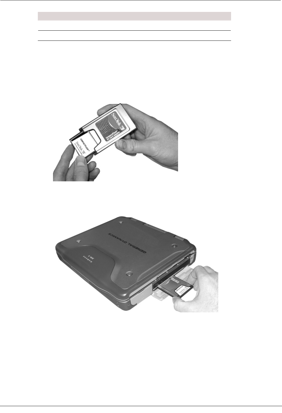
Using the PCMCIA Flash Card Adapter
The GoBook has a PCMCIA slot that, with an adapter, you can use to read compact flash
cards.
The PCMCIA slot is on the right side of the GoBook, just below the CD drive.
ID Description
1 Front of the GoBook XR-1
Hardware Installation Guide 7
Chapter 1 Using the MC3 System
ID Description
2 PCMCIA slot
3 CD drive
The compact flash card should come installed from the factory. If it is not installed or you
wish to replace cards, use the following procedures.
To insert the flash card adapter
1. Slide the flash card into the PCMCIA adapter.
2. Open the CD drive / PCMCIA slot compartment on the right-hand side of the
GoBook.
3. Slide the adapter into the PCMCIA slot on the GoBook until it clicks into place.
To remove the flash card adapter
1. Open the CD drive / PCMCIA slot compartment on the right-hand side of the
GoBook.
8 Hardware Installation Guide
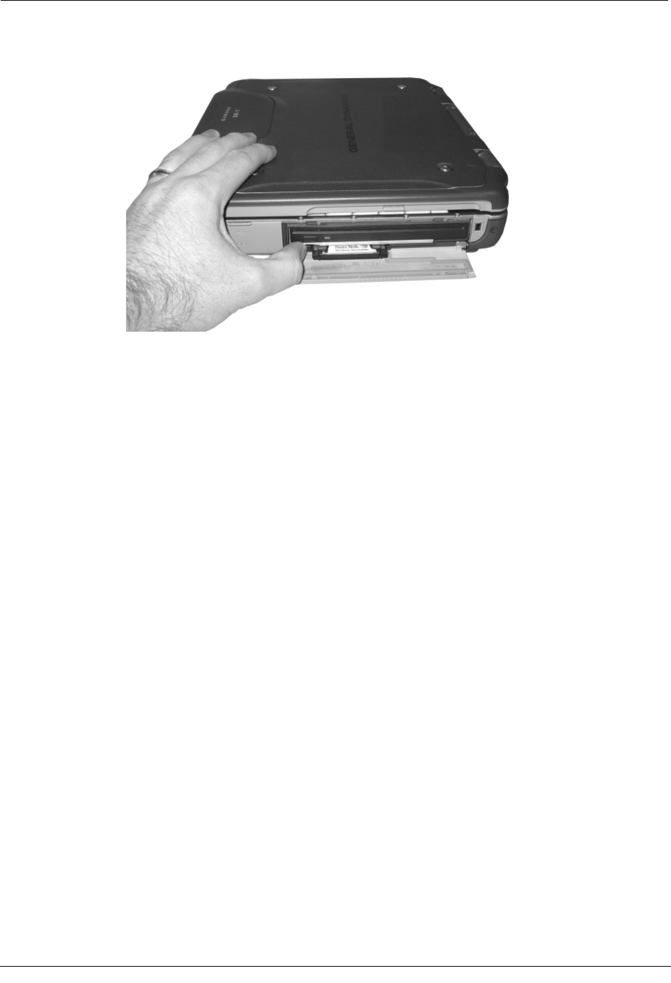
Installing the MC3 System
2. Push the button in until the adapter pops out of the slot.
3. Pull the adapter the rest of the way out.
4. Remove the compact flash card from the adapter.
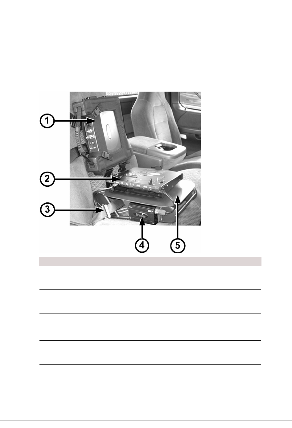
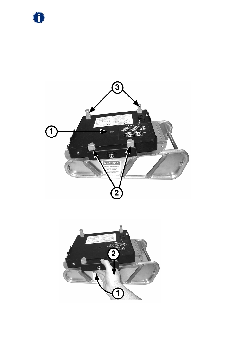
Mounting the MC3
The MC3 is mounted in a harness that can be attached to either a bucket- or bench-seat in a
vehicle. The harness contains clips on the top for mounting it on a bucket seat, and clips on
the side for bench seat mounting. The MC3 is shipped in its vehicle mount, with the straps
set up for a bucket seat. The bench straps are included in the container the MC3 was
shipped in.
Mount the sled before mounting the MC3 on the seat.
If you are using a sled to secure the GoBook, be sure to mount the MC3 high enough on the
seat that the sled and laptop will fit easily beneath it. If you are using a pedestal mount, the
MC3 can be attached lower if desired.
To mount the MC3 on the seat
1. If the MC3 radio has been removed from its harness:
• Slide the radio into its harness, with the MC3 label showing through the
opening on the front of the harness.
Hardware Installation Guide 9
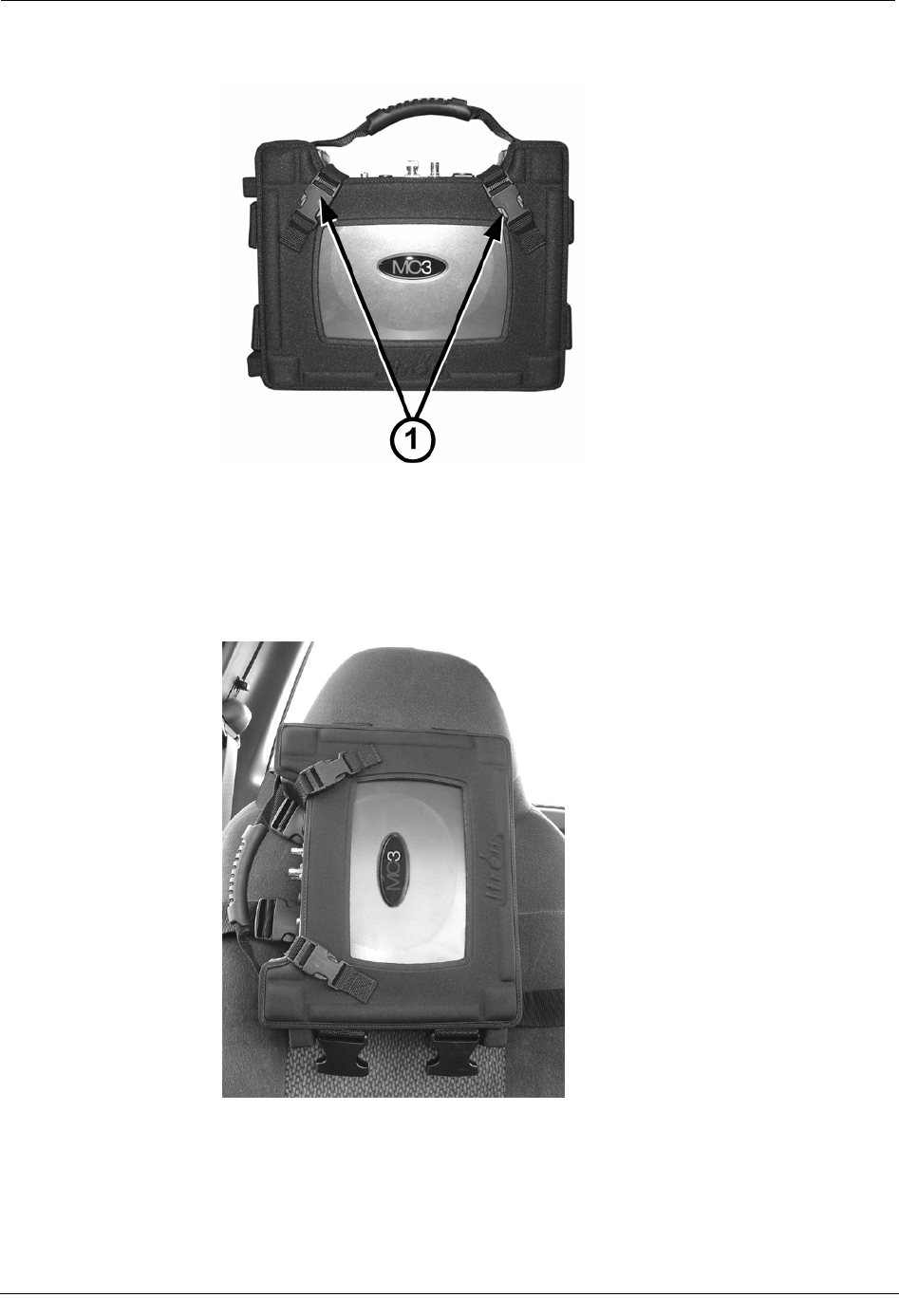
Chapter 1 Using the MC3 System
• Secure it in place by buckling the two diagonal corner straps (1).
2. Strap the mount to either the front or the back of the passenger-side seat back.
Position the unit within the mount so that when it is strapped to the seat back, the
unit's connectors face toward the passenger-side door.
• Sled Systems If you will be installing a sled, be sure to mount the MC3 high
enough on the seat back so that the sled and laptop will fit beneath the radio on
the seat.
• Pedestal Systems If you will be attaching the GoBook to a dock on a pedestal,
the MC3 radio can be attached lower on the seat. This configuration is shown in
the following examples.
Depending on whether the vehicle has a separate passenger-side bucket seat or a
bench seat, do one of the following:
10 Hardware Installation Guide
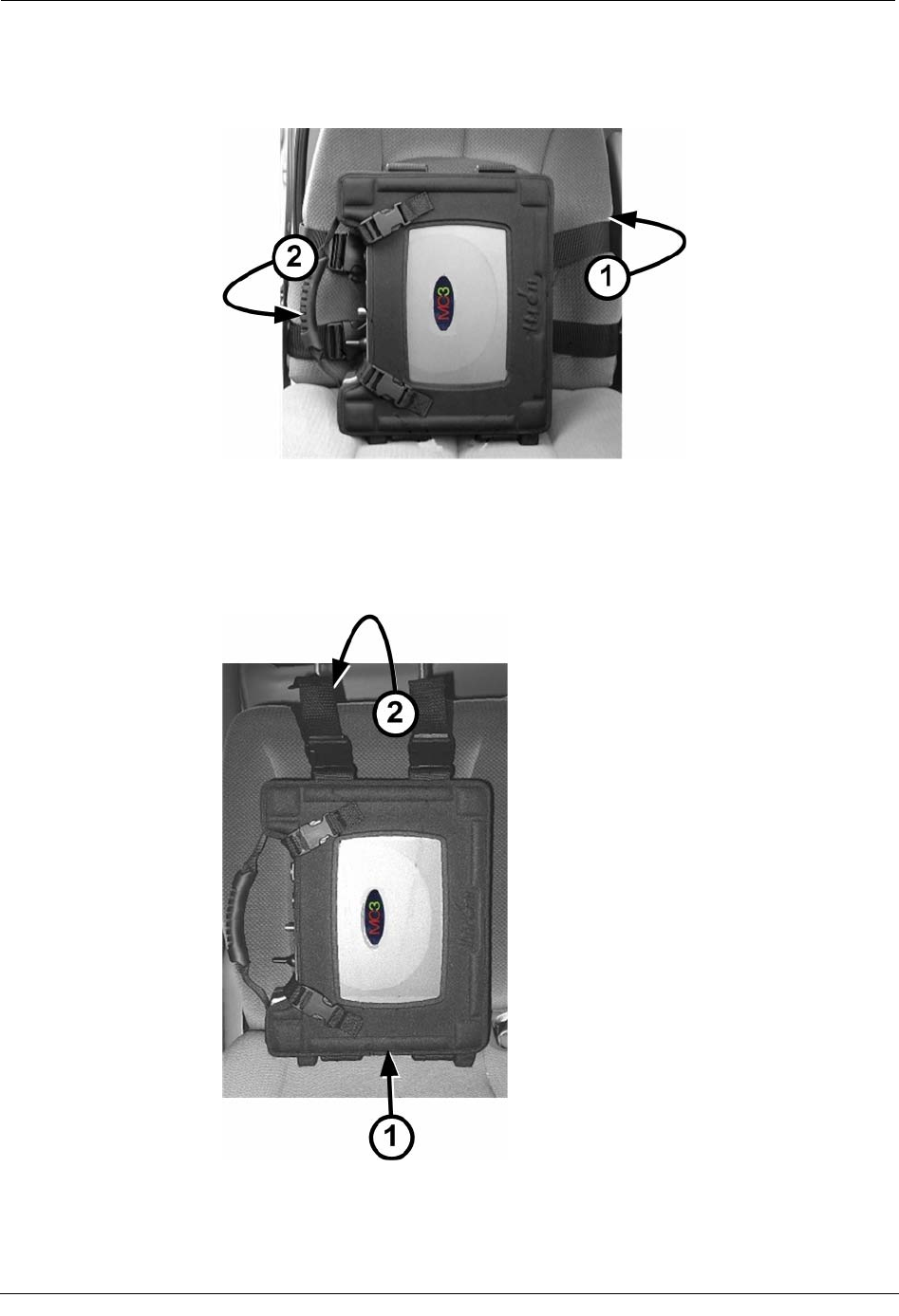
Installing the MC3 System
• Bucket Seat Extend the mounting straps from the driver-facing side of the
vehicle mount (1), and then wrap them around the seat back and buckle them to
the opposite side of the vehicle mount (2).
• Bench Seat Connect the optional bench-seat straps to the buckles on the
bottom of the vehicle mount.
Push the free ends of the straps between the seat cushion and the seat back (1),
and then extend them up and over the top of the seat back and connect them to
the buckles on the top of the vehicle mount (2).
3. Tighten the straps until the MC3 is snug against the seat back.
Hardware Installation Guide 11
Chapter 1 Using the MC3 System
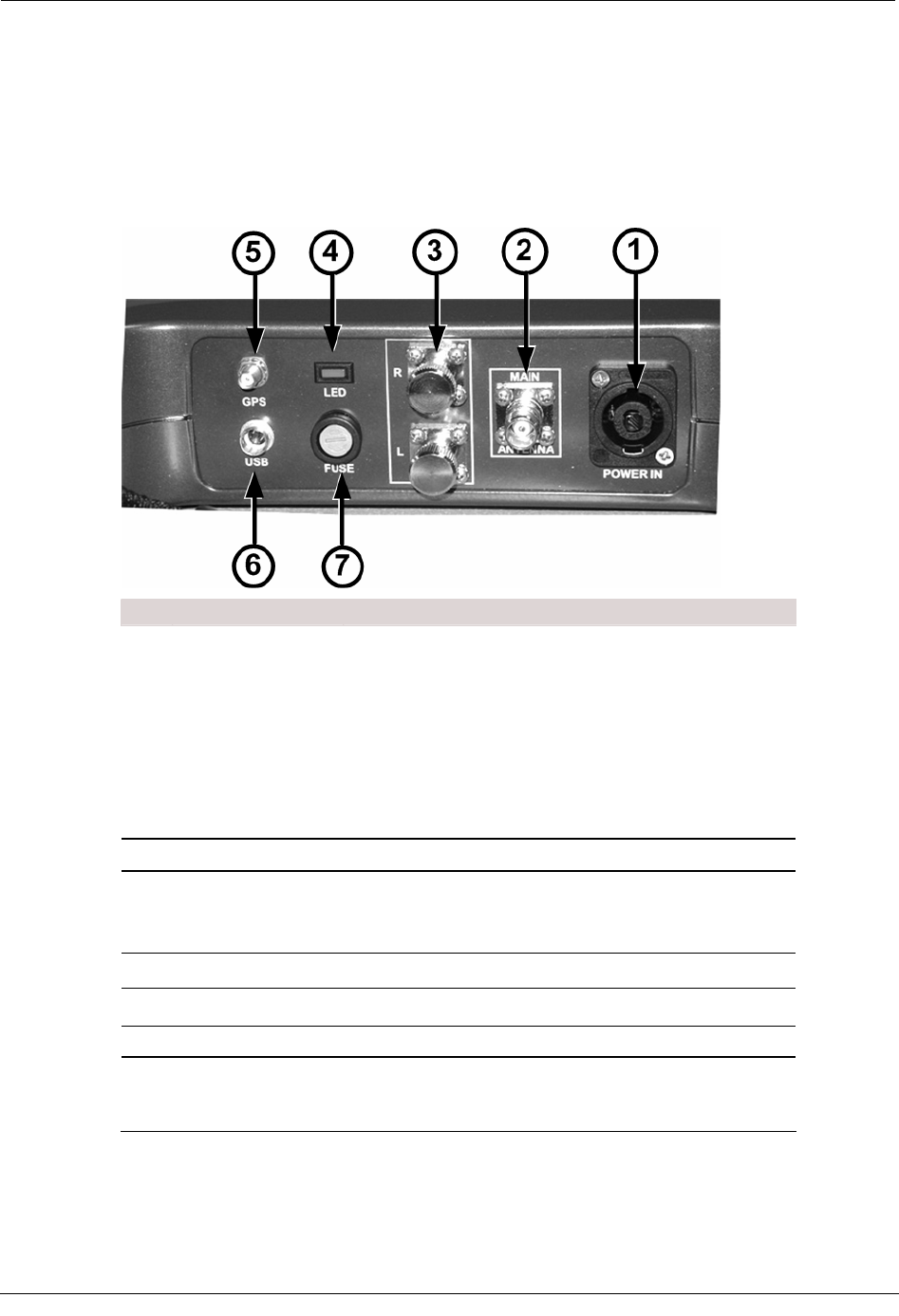
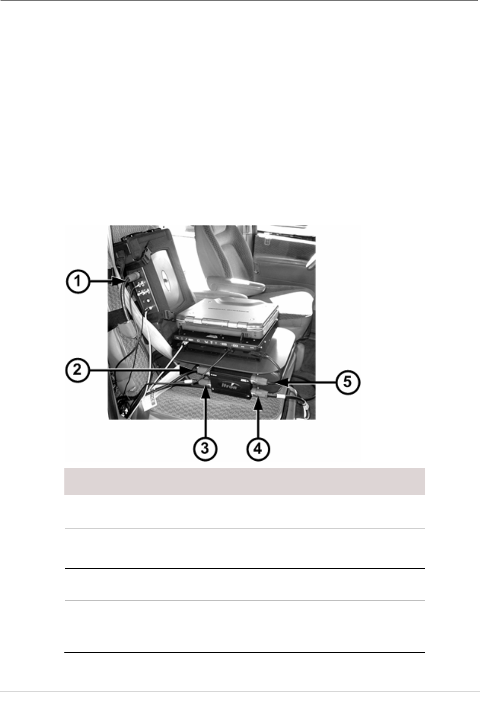
Connecting the GoBook XR-1 to the MC3
The MC3 rides in a harness that attaches to bucket- or bench-style passenger seat. The sled
for the GoBook XR-1 is equipped with a dock for the computer and a junction box for
power connectors (the junction box must be attached to the sled prior to use). The sled
should be mounted on the seat before the MC3 radio is attached. The MC3 must be
mounted high enough on the seat so that the right side ports on the GoBook are accessible,
as shown in the example below.
ID Component Description
1 MC3 radio Houses components necessary for collecting
mobile reads, such as the processors,
receivers, and GPS equipment.
2 Laptop dock Provides a communication link between the
GoBook and the MC3 radio. Also provides
power to the laptop.
3 Seat belt pretensioner Secures the sled in the vehicle.
A properly installed sled is vital to ensure
your safety while collecting reads.
4 Junction box Receives power from the vehicle and
distributes it to the MC3 radio, GoBook, and
optional equipment.
5 Sled Attaches to the passenger seat of a vehicle
and secures the GoBook and dock in place.
12 Hardware Installation Guide
Installing the MC3 System
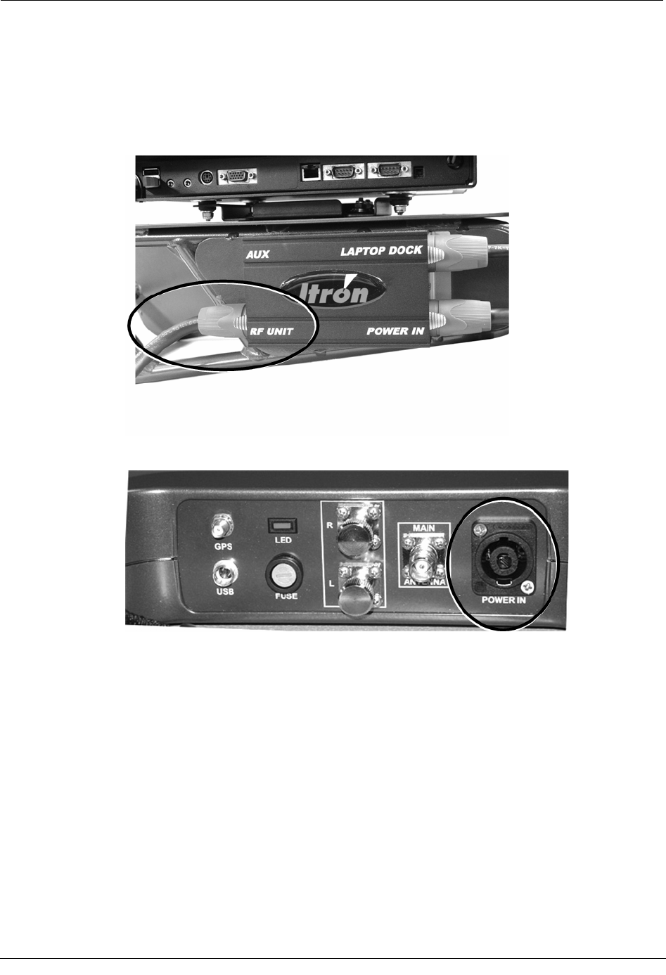
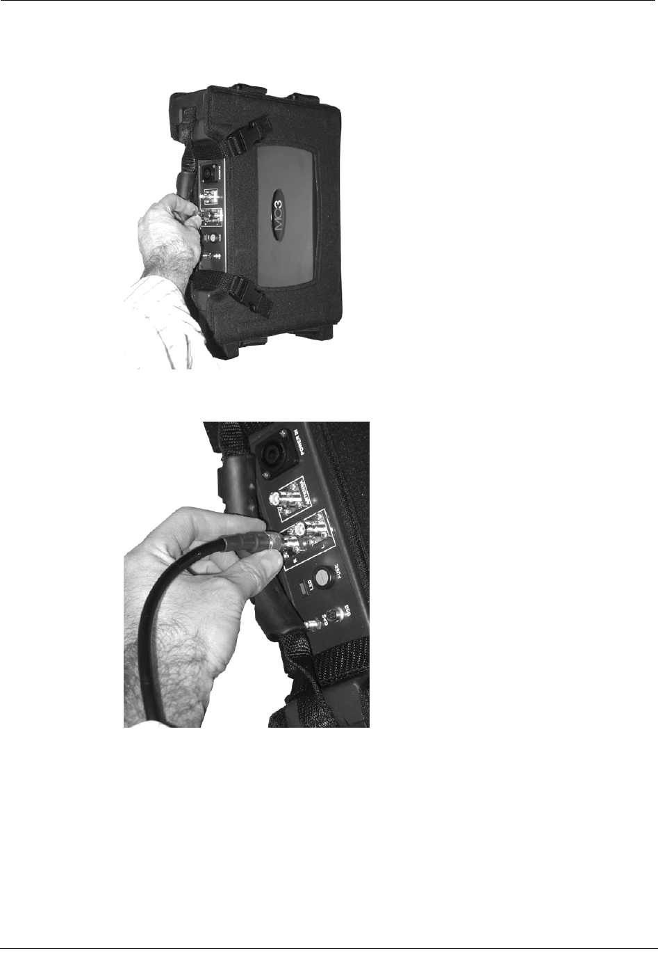
MC3 Connectors
The top of the MC3 radio contains the power and communications connectors, as well as a
fabric and rubber handle used to carry the radio.
The connections on the MC3 are described in the following table.
ID Connector Description
1 Vehicle power Input that receives the connector running to the vehicle
power source to provide power to the MC3.
In addition to wiring the power cable directly to the
vehicle, a cigarette lighter power cable is available for
emergency use only. Using this cable will disable the
power management functions of the MC3 and could
adversely affect system performance. Disconnect this cable
from the power source when not in use. Failure to do so
could result in a dead battery.
2 Main antenna Connector for the roof-mounted antenna cable.
3 Side-looker antennas
Extra connectors for optional side-looking, roof-mounted
antennas.
Do not use these connectors for the main MC3 antenna.
4 Power indicator An LED that turns on when the MC3 is receiving power.
5 GPS antenna Connects the MC3 to the roof-mounted GPS antenna.
6 USB Connects the GoBook to the MC3 radio.
7 Fuse holder Holder accepts standard automotive 12V (15 amp) ATO
fuse (included) to protect internal circuitry from power
surges by the vehicle.
Hardware Installation Guide 13
Chapter 1 Using the MC3 System
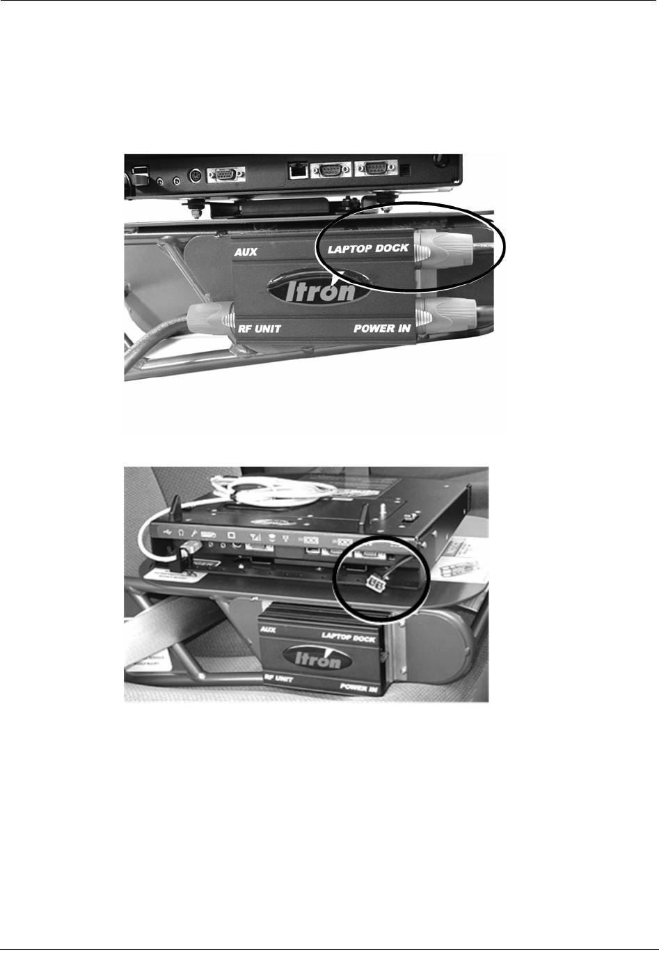
Connecting the Power Cables
Power to the Mobile Collection components is distributed through the junction box on the
side of the sled. There are three power cables that must be connected:
• Vehicle power to the junction box
• Junction box to the GoBook dock
• Junction box to the MC3
There is a fourth outlet on the junction box called AUX. It is for powering the EkaNet radio,
an optional device for mobile demand reset functionality.
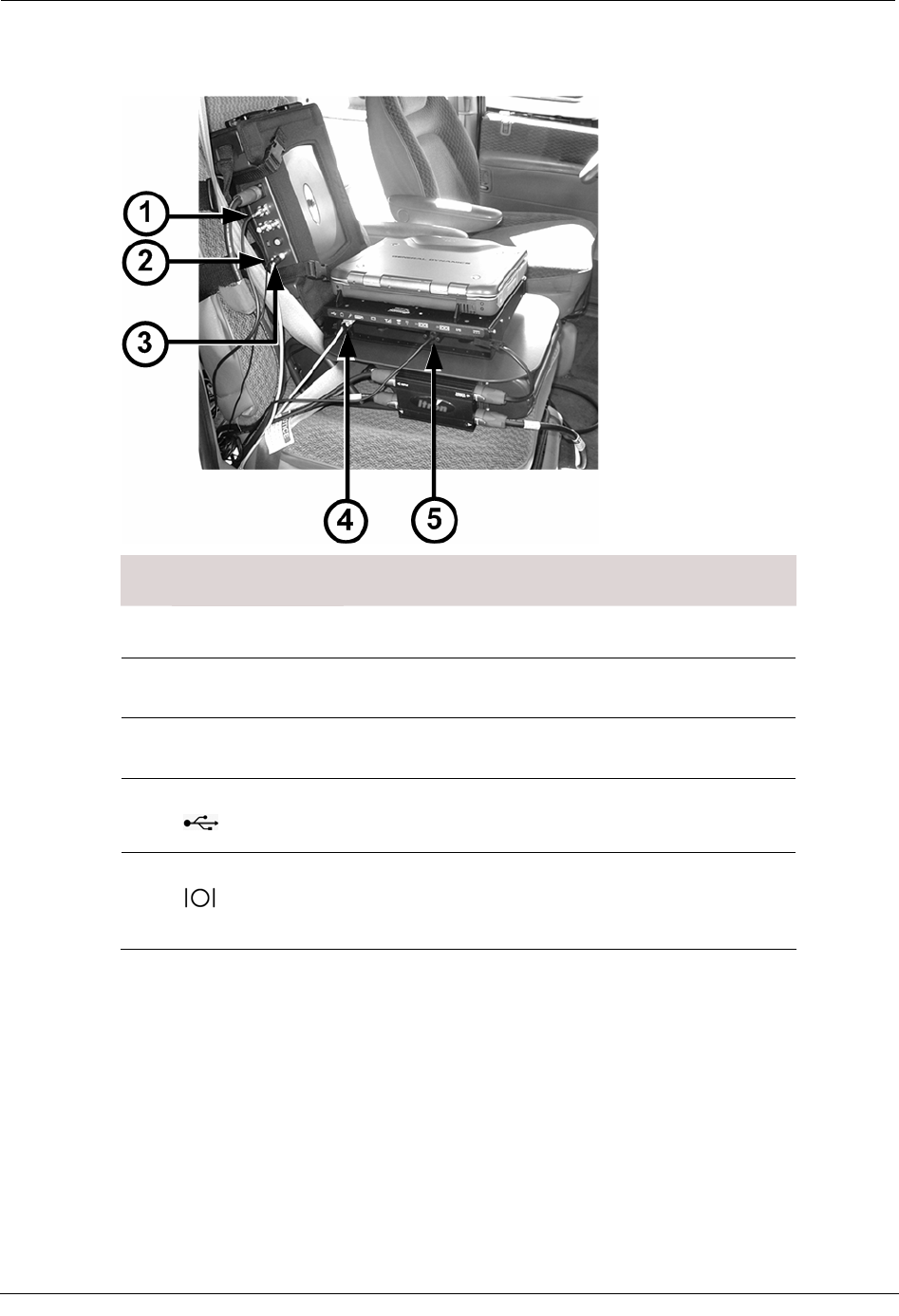
The example below shows an MC3 radio and sled for a GoBook XR-1 with all the power
cables connected.
ID Connection
(Label)
Description
1 Power in to MC3 radio
(POWER IN) Power receptacle on MC3 radio.
2 Power to EkaNet radio
(AUX)
Connection from junction box to optional EkaNet radio.
Supplies power to the EkaNet radio for mobile demand
reset functionality.
3 Power out to MC3 radio
(RF UNIT)
Connection from junction box to MC3 radio.
4 Power in from vehicle
(POWER IN)
Power source input from the vehicle's battery. This
connection is hard-wired to the vehicle battery; see the
Vehicle Preparation Guide (TDC-0382-xxx) for more
information.
14 Hardware Installation Guide
Installing the MC3 System
ID Connection Description
(Label)
5 Power out to laptop
dock
(LAPTOP DOCK)
Connection from junction box to the laptop dock. The
laptop dock secures the GoBook in place while you drive
a route, and provides power and communication
connections for the laptop. The dock is attached to either
a sled or pedestal mount in the vehicle (a sled is pictured
in this example).
To connect the vehicle power to the sled
• Plug the vehicle power cable into the POWER IN receptacle on the junction box. Pull
the silver tab on the power cable back, insert the connector into the junction box, twist
the connector so the silver tab lines up with the labeling on the junction box, and
release the tab to lock it into place.
The other end of the power cable is hard-wired to the vehicle battery as described in
the Mobile Collection Vehicle Preparation Guide (TDC-0382-xxx).
Hardware Installation Guide 15
Chapter 1 Using the MC3 System
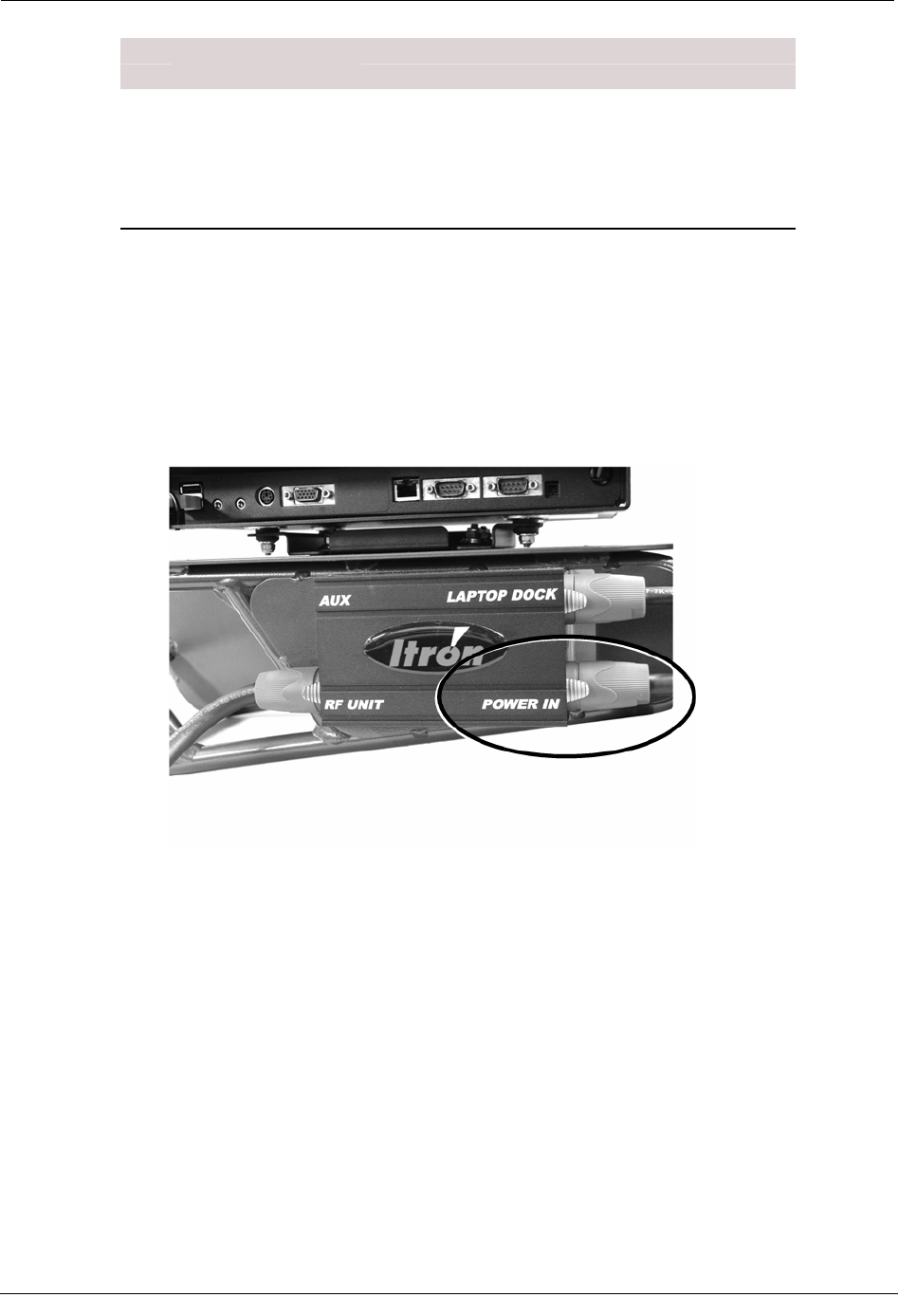
To connect power to the GoBook dock
1. Plug the red and blue end of the cable into the LAPTOP DOCK receptacle on
junction box. Pull the silver tab on the power cable back, insert the connector into the
junction box, twist the connector so the silver tab lines up with the labeling on the
junction box, and release the tab to lock it into place.
2. Plug the pigtail end into the dock connector.
16 Hardware Installation Guide
Installing the MC3 System
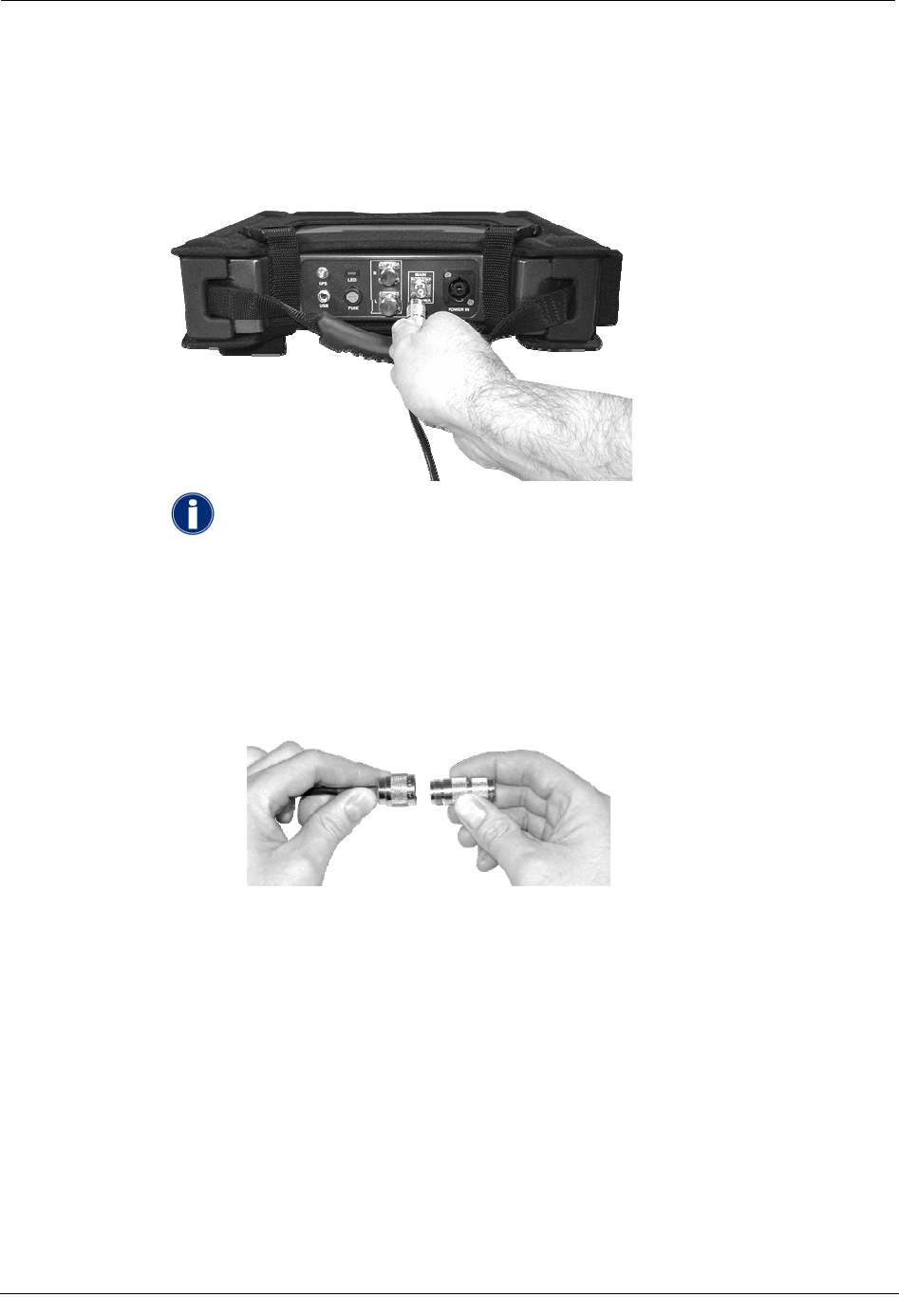
To connect power to the MC3
1. Plug one end of the cable into the RF UNIT receptacle on the junction box. Pull the
silver tab on the power cable back, insert the connector into the junction box, twist the
connector so the silver tab lines up with the labeling on the junction box, and release
the tab to lock it into place.
2. Plug the other end into the POWER IN receptacle on the MC3.
Connecting the Antenna
Next, connect the omni-mount RF antenna to the radio.
This antenna has either a fixed-base that is permanently attached to the vehicle, or a
magnetic base that can be attached to and removed from the vehicle as necessary.
Hardware Installation Guide 17
Chapter 1 Using the MC3 System
To connect the antenna
• Connect the omni-mount RF antenna cable to the MAIN ANTENNA connector on the
MC3. Be sure to properly tighten the connector; a loose connection can lead to poor
radio and read performance.
When using older antenna cables with type N connectors along with the
MC3 radio, a type N to TNC adapter is required; this adapter is included
in the MC3 kit.
Attach the adapter securely to both the antenna cable and MC3 to ensure
optimal radio performance. Should you need another adapter or are not
able to locate the adapter in the ship kit, you will need to contact your
Itron representative or Customer Service (1.800.635.8725) to place an
order for an adapter (part number CON-0419-001).
Connecting Side-Looker Antennas
The MC3 radio supports an additional set of antennas that help gather additional reads from
endpoints located on the sides of the vehicle.
The side-looker antennas are an optional component of the MC3 system that can help
improve read coverage in certain situations (contact your Itron representative for more
information). Two additional antennas are connected to one antenna base, which is then
installed on the vehicle.
18 Hardware Installation Guide
Installing the MC3 System
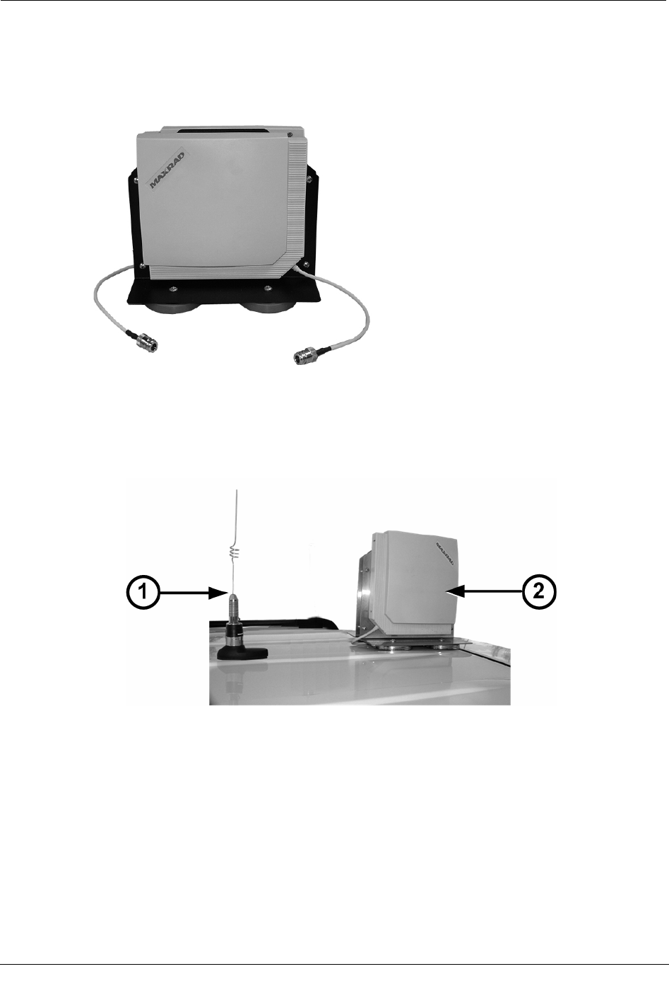
Side-looker antennas attach to the top of the vehicle with several strong magnets. If your
vehicle has a fiberglass top, the antennas may not bond securely to the vehicle; Itron does
not recommend the use of side-looker antennas with fiberglass-topped vehicles.
To connect the side-looker antennas
1. Mount the side-looker antennas (2) on top of the vehicle, two feet in front of or behind
the primary RF omni-mount antenna (1).
2. Route the antenna cables into the vehicle.
Hardware Installation Guide 19
Chapter 1 Using the MC3 System
3. Remove the caps covering the side-looker antenna ports, identified by R and L on the
MC3 radio in the vehicle.
4. Connect the side-looker antenna cables to the R and L antenna inputs on the MC3
radio.
Connecting the Data Cables
There are two communications cables for receiving and transferring GPS and meter data
between MC3 and the GoBook:
• A USB cable from the GoBook dock to the MC3
• A serial cable from the EkaNet radio to the GoBook dock (only for electric meter
mobile demand reset).
20 Hardware Installation Guide
Installing the MC3 System
The following picture shows a Mobile Collection system with all the data cables connected.
ID Connection
(Label)
Description
1 RF radio antenna
(MAIN ANTENNA) RF radio antenna connection on MC3 radio. Receives
endpoint signals.
2 GPS antenna
(GPS)
GPS antenna connection to MC3 radio. Receives GPS
signal for vehicle location and tracking.
3 USB data cable
(USB)
USB data output from MC3 radio. Data is transferred from
the radio to the laptop through this cable.
4 USB data cable
( )
USB data input on the laptop dock. Data from the MC3
radio is transferred to the Mobile Collection software
running on the laptop.
5 Serial cable to EkaNet
( )
Serial port connection from the laptop dock to an optional
EkaNet radio. The cable transfers data from EkaNet
equipped endpoints to the laptop for mobile demand reset
functionality.
To connect the USB data cable
1. Ensure that the rectangular end of the USB cable (1) is inserted into the GoBook dock
USB port.
Hardware Installation Guide 21
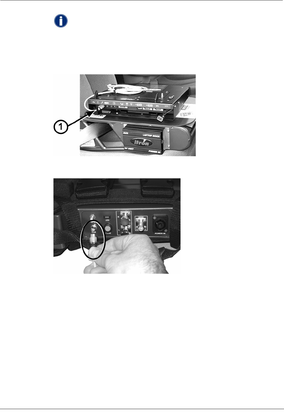
Chapter 1 Using the MC3 System
The USB cable is connected to the dock at the factory and is secured with a
cable tie. DO NOT remove this cable tie or unplug the USB cable from the
dock. The cable tie helps ensure a secure connection and should never be
disconnected. The cable tie also ensures that the correct COMM port is used
for GPS communications with the Mobile Interface software. Using a
different USB port will prevent the MC3 radio from communicating
properly with the software.
2. Plug the round end of the USB cable into the MC3 radio by pulling the connector
sleeve back, plugging the connector in to the receptacle, and releasing the sleeve.
Attaching Older GoBooks to the MC3
This section explains how to connect older GoBook models to the MC3.
• GoBook III This GoBook can be attached directly to the vehicle dock, mounted on a
pedestal by the driver or on a sled (similar to the GoBook XR-1).
• GoBook MAX This GoBook must be attached to the vehicle dock on a pedestal
mount; no sled option is available.
Attaching the GoBook III to the Vehicle Dock
You can attach the GoBook III to a vehicle dock on a sled or pedestal near the driver. The
vehicle dock must be installed on the sled or pedestal before attaching the GoBook III.
Refer to the Itronix Vehicle Cradle Installation Guide for detailed instructions.
22 Hardware Installation Guide
Installing the MC3 System
The Itronix documentation refers to the laptop receptacle as a cradle; Itron uses
the term dock to identify this piece of equipment. The term dock is used repeatedly
throughout this manual; however, dock and cradle are interchangeable.
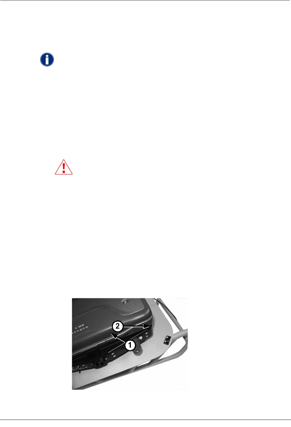
To attach the GoBook III to the vehicle dock
1. Ensure that the vehicle dock is in the unlocked position. When locked, a steel pin (1)
is visible on the top of the vehicle dock; this pin helps secure the GoBook III in place.
When unlocked, this pin is not visible. The front (2) and rear (3) mounting guides are
also extended out to the perimeter of the dock when unlocked.
• To unlock the dock, push in underneath the locking mechanism (1) and then
pull the handle out (2) as shown.
2. Lower the GoBook III onto the vehicle dock, making sure that the two rear locking
mechanisms on the top of the vehicle dock fit into the mating holes on the GoBook
underside.
Hardware Installation Guide 23
Chapter 1 Using the MC3 System
3. Once the GoBook is properly aligned on the vehicle dock, push the locking
mechanism in (1) to secure it. This locks the pin in place on the underside of the
GoBook and also engages the mounting guides.
4. One end of the USB data cable comes attached to the vehicle dock; attach the other
end to the USB port on the MC3.
The USB cable is connected to the dock at the factory and is secured with
a cable tie. DO NOT remove this cable tie or unplug the USB cable from
the dock. The cable tie helps ensure a secure connection and should never
b
e disconnected. The cable tie also ensures that the correct COMM port is
used for GPS communications with the Mobile Interface software. Using
a different USB port will prevent the MC3 radio from communicating
properly with the software.
5. Connect the antennas and power cables for the MC3 as described earlier in this
document.
24 Hardware Installation Guide
Removing the MC3 System
Removing the MC3 System
At some point, you may need to remove the Mobile Collection system from the vehicle.
Before removing any Mobile Collection system components, be sure to
stop the Mobile Interface software, shut down the GoBook, and turn off
the vehicle power. See the Mobile Collection User's Guide (TDC-0380-
xxx) for more information.
To remove the GoBook from the vehicle dock
1. Stop processing reads.
2. Complete routes.
3. Export routes.
4. Shut down all open applications and then shut down the GoBook.
CAUTION If you accidently disconnect the GoBook from the MC3
radio before shutting down Windows and the laptop, the following
message appears:
Unsafe Removal of Device
Before clicking OK, clear the ShowUnplug/Eject icon on the Taskbar
box. If you do not clear this box, you will not be able to properly shut
down the system in the future.
5. Close the GoBook screen.
6. Turn off the vehicle.
7. Disconnect any cables attached directly to the GoBook.
8. If unlocking the GoBook from the vehicle cradle:
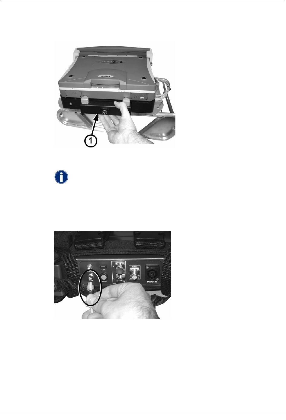
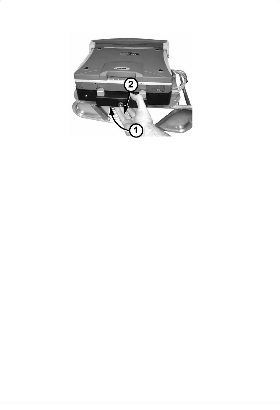
• GoBook XR-1 Push the locking mechanism in and slide it toward the keys on
front of the dock (1), and then push it in a little further and pull it back to the
starting position to unlock the dock (2).
Hardware Installation Guide 25
Chapter 1 Using the MC3 System
• GoBook III Push in underneath the locking mechanism (1) and then pull the
handle out (2) as shown.
9. Gently lift the GoBook up and away from the cradle.
Disconnecting the Cables
Disconnect the cables from the MC3 and leave them in the vehicle for the next installation
of the system.
To disconnect the cables
1. Complete the procedure To remove the GoBook from the vehicle dock on page 25.
2. Unplug the cables from the MC3 radio.
3. Unplug all the cables from the GoBook dock EXCEPT for:
• The USB cable (both XR-1 and GoBookIII docks).
• The power cable that is hard-wired to the dock for GoBookIII installations.
4. Unplug the cables from the sled or pedestal junction box.
5. Release the mounting clips on the MC3 harness and remove the MC3 radio.
6. Unbuckle the seat belt securing the sled to the passenger seat and remove the sled
from the vehicle. Leave the pretenstioner attached to the seat belt.
26 Hardware Installation Guide
CHAPTER 2
Using the Mobile Collection 2.x System
This chapter describes how to install and use legacy versions of the Mobile Collector radio.
If your vehicle has a passenger-side airbag, Itron strongly recommends disabling
it when the Mobile collection system is installed. The force of the airbag deploying
could damage the laptop, radio, or other components of the system.
About the Mobile Collection 2.x System
The Mobile Collector 2.x radio houses the transmitter, receivers, and other electronics
required to communicate with endpoints.
There are two versions of the Mobile Collector radio; one for use with the GoBook MAX
and one for use with the GoBook III. Both versions contain the same features and
functionality, but may look slightly different, depending on the version of GoBook you are
using.
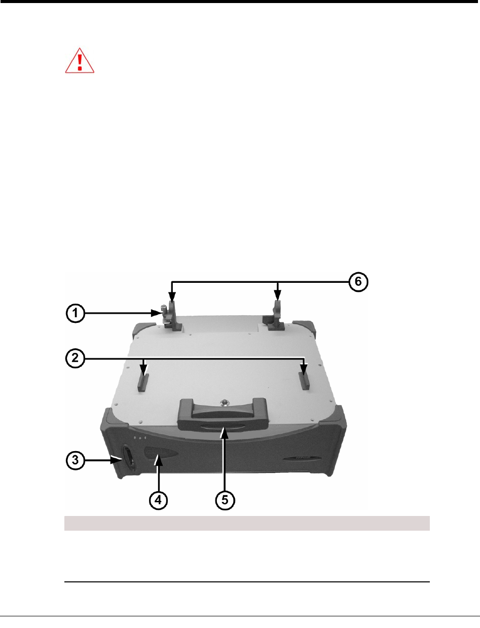
Mobile Collector 2.x Radio - GoBook III
ID Component Description
1 USB cable clip Secures the USB cable that connects the GoBook
III to the Mobile Collector radio. The cable clip
prevents the USB cable from coming loose while
driving a route.
Hardware Installation Guide 27
Chapter 2 Using the Mobile Collection 2.x System
ID Component Description
2 Mounting guides Hold the GoBook in place, and assist you in
placing the GoBook on the radio in the proper
location.
3 Flash card reader Provides data backups when configured through
the Mobile Administration function.
4 LEDs Indicate system power, operation, and flash card
status.
5 Locking mechanism Secures the GoBook to the top of the radio.
6 Screen rests Provide support for the GoBook III screen.
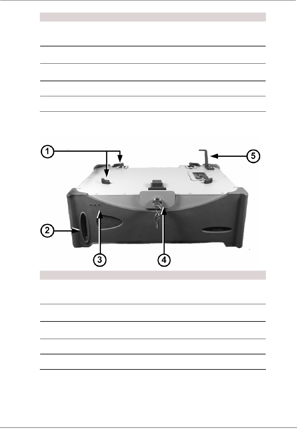
Mobile Collector 2.x Radio - GoBook MAX
ID Component Description
1 Mounting guides Hold the GoBook in place, and assist you in
placing the GoBook on the radio in the proper
location.
2 Flash card reader Provides data backups when configured through
the Mobile Administration function.
3 LEDs Indicate system power, operation, and flash card
status.
4 Locking mechanism Secures the GoBook to the top of the radio.
5 Screen rest Provides support for the GoBook MAX screen.
28 Hardware Installation Guide