Itron DCU5310 Mobile collection device for utility metering User Manual Hardware Installation Guide
Itron, Inc. Mobile collection device for utility metering Hardware Installation Guide
Itron >
Contents
- 1. Users Manual Part 1
- 2. Users Manual Part 2
- 3. Final Users Manual
Users Manual Part 2

About the Mobile Collection 2.x System
Flash Card Reader
Route data can be transferred to and from the Mobile Collector using a removable flash card
(two CompactFlash® cards are supplied). The Windows operating system on the GoBook
recognizes the flash card as a removable drive, allowing standard file access.
Periodic data backups to the flash card can be configured in the Mobile Administration
application; see the Mobile Collection Administration Guide (TDC-0381-001) or Online
Help for more information.
See the Mobile Collection User's Guide (TDC-0380-xxx) or Online Help for more
information on using the flash card in day-to-day activities.
Compact Flash Cards
The Mobile Collection system includes two SanDisk CompactFlash cards. If you require
more cards, you may purchase them through Itron or through electronics stores or
distributors.
Use of unapproved cards can result in loss of data.
If you purchase additional cards from a distributor or electronics retailer, Itron recommends
the following:
• 64M SanDisk Industrial Grade, Extended Temperature range
• 64M Hitachi Renesas, Industrial Grade, Wide Temperature, or Extended Temperature
range
LEDs
Three LEDs signal system power, system operation, and flash card status. Errors relating to
the transmitter and receivers display on the GoBook within the Mobile Interface.
The table below describes the LED status indicators.
LED Color Description
Red Voltage error condition
Flashing Green Vehicle accessories power on, ignition off
Green Vehicle ignition on
Power/Error 1
None System is shutting down or completely off
Operate/Error 2 Red Temperature error condition
Hardware Installation Guide 29
Chapter 2 Using the Mobile Collection 2.x System
LED Color Description
Green Operating normally
None System is shutting down or completely off
Red Data transferring to/from the flash card
reader
Flash Card
None System is shutting down or completely off
Locking Mechanism
The locking mechanism attaches the GoBook to the Mobile Collector. Locking the GoBook
to the Mobile Collector reduces the likelihood of the GoBook separating from the Mobile
Collector in the event of a collision.
The GoBook MAX has a keyed locking mechanism; the GoBook III has a keyless locking
mechanism.
WARNING! Do not set down the Mobile Collector on its front face while
carrying it by the handle or at any time. Doing so may damage the flash card
reader or the flash card, or may break off the key if it was left in the mounting
lock.
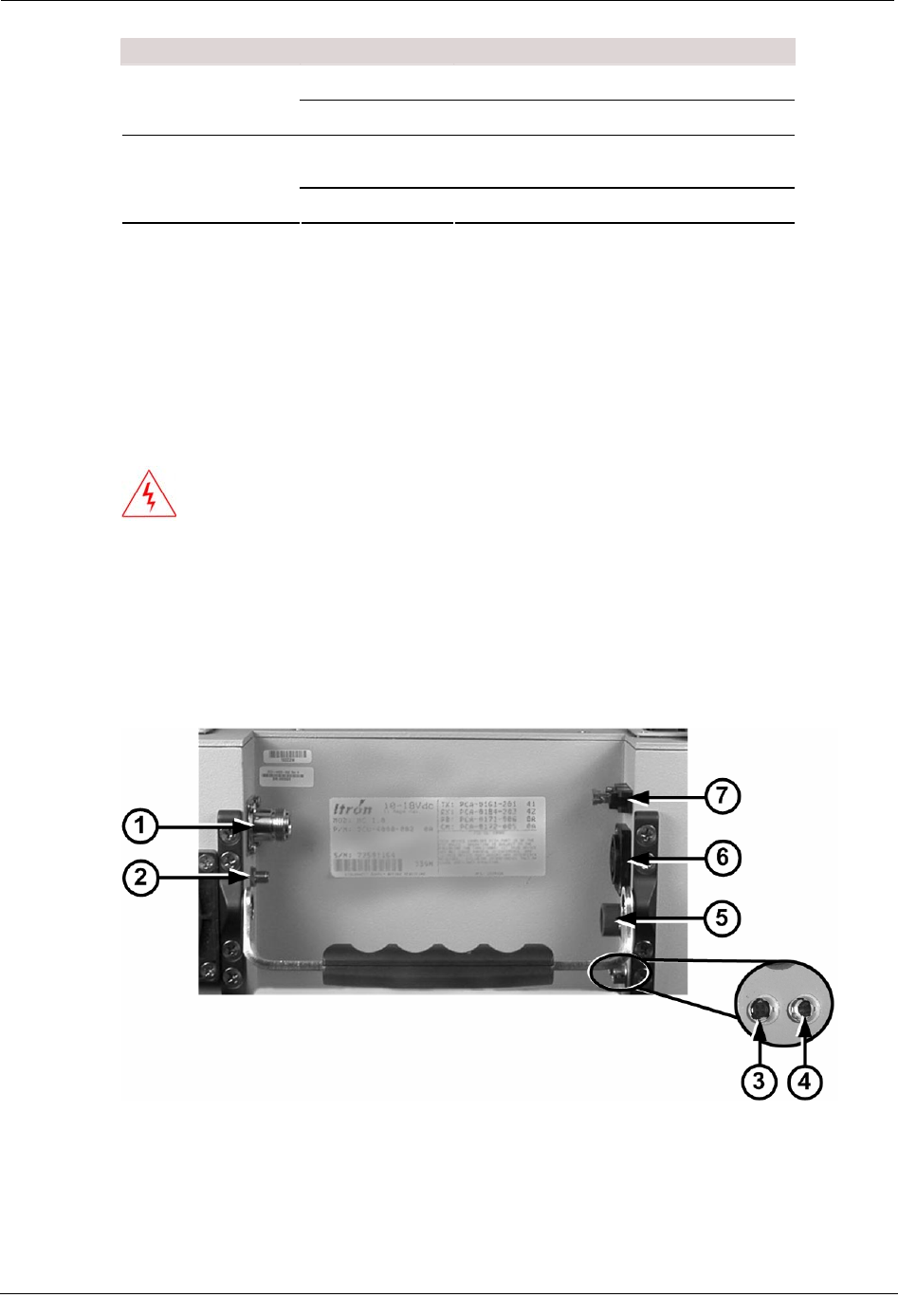
Rear Connectors
The rear of the Mobile Collector 2.x radio contains the power and communications
connectors.
30 Hardware Installation Guide

About the Mobile Collection 2.x System
ID Connector Description
1 RF antenna Connects to the roof-mounted antenna. See the
Mobile Collection Vehicle Preparation Guide.
Itron provides a magnetic mount option for the
RF antenna. This magnetic mount is intended as
a temporary solution and it is for emergency use
only. Long-term use of a magnetic mount
antenna could adversely affect system
p
erformance and is not a supported configuration
of this product.
2 GPS antenna Connects to the externally-mounted GPS
antenna. This gold-plated connector is used with
the optional Mapping feature of the Mobile
Interface software.
3 USB Connects the GoBook III computer to the radio
for data transfer.
Also for use with a GoBook computer not
mounted directly to the Mobile Collector radio.
See Vehicle Dock / Pedestal Option on page 33
for more information.
Mobile Collector radios for use with the GoBook
MAX have a USB data connection built into the
radio lid.
4 GPS receiver Connects to an external GPS receiver box when
using a version 2.0 radio.
Version 2.5 radios have a GPS receiver built into
the Mobile Collector, so this connector is not
used with a 2.5 radio.
5 GoBook III power Provides power to the GoBook III laptop.
Mobile Collector radios for use with the GoBook
MAX have a power connection built into the
radio lid.
6 Power in Receives power from the vehicle and distributes
it to the radio and GoBook.
In addition to wiring the power cable directly to
the vehicle, a cigarette lighter power cable is
available for emergency use only. Using this
cable will disable the power management
functions of your Mobile Collector and could
adversely affect system performance.
ALWAYS disconnect this cable from the power
source when not in use. Failure to do so could
result in a dead vehicle battery.
7 Fuse holder and fuse Provides over-current protection for the radio.
Holder accepts standard automotive 12V (15
amp) ATO fuse (included) to protect internal
circuitry from power surges by the vehicle.
Hardware Installation Guide 31
Chapter 2 Using the Mobile Collection 2.x System
Mobile Collector Sled
The Mobile Collector sled is a mounting bracket designed to secure the Mobile Collector
radio in the vehicle and support it and the GoBook in an upright position on the passenger
seat.
GoBook Mounting Systems
There are two mounting options for the GoBook:
• Direct Mount Option The GoBook mounts directly on the Mobile Collector.
• Vehicle Dock / Pedestal Option The GoBook mounts remotely on a free-standing
pedestal, using the Itronix vehicle cradle.
The Itronix documentation refers to the laptop receptacle as a cradle; Itron uses
the term dock to identify this piece of equipment. The term dock is used repeatedly
throughout this manual; however, dock and cradle are interchangeable.
WARNING! Improperly installed or secured components may
result in injury or death in the event of a collision. Install and secure
the system components in accordance with this document, the
Mobile Collection Vehicle Preparation Guide, the Mobile Collection
Sled and Pretensioner Installation Guide, manufacturer installation
instructions, and applicable safety standards.
Direct Mounting Options
The GoBook communicates with the Mobile Collector and receives power from it through
the mounting connector, providing fast, easy docking and removal, without additional
cables.
The GoBook MAX mounts onto the Mobile Collector radio within the mounting guides so
that the mounting connector and the external modem connector insert into mating
connectors on the underside of the GoBook. A key inserted into the locking mechanism
turns clockwise to lock the GoBook in place.
32 Hardware Installation Guide
Installing the Mobile Collection 2.x System
The GoBook III mounts onto the Mobile Collector radio within the mounting guides, but
communicates through a USB cable and is powered from a cable connected to the Mobile
Collector.
Vehicle Dock / Pedestal Option
Optionally, you may mount the GoBook on a vehicle cradle that is attached to a pedestal.
This option allows you to position the Mobile Collector in the vehicle so that it is closer to
the driver, while placing the Mobile Collector and its base elsewhere in the vehicle. A key
inserted into the locking mechanism turns clockwise to lock the GoBook MAX in place; a
similar mechanism will be available for use with the GoBook III.
Installing the Mobile Collection 2.x System
This section shows you how to properly install a Mobile Collection 2.x system, with either a
GoBook III or a GoBook MAX.
Attach the Mobile Collector 2.x to the Sled
A plate installed on the underside of the Mobile Collector contains holes and slots that mate
with the pins on top of the sled. Attach the Mobile Collector to the sled by lowering it onto
the pins and rotating it so that the pins slide into the slots, locking the Mobile Collector in
place.
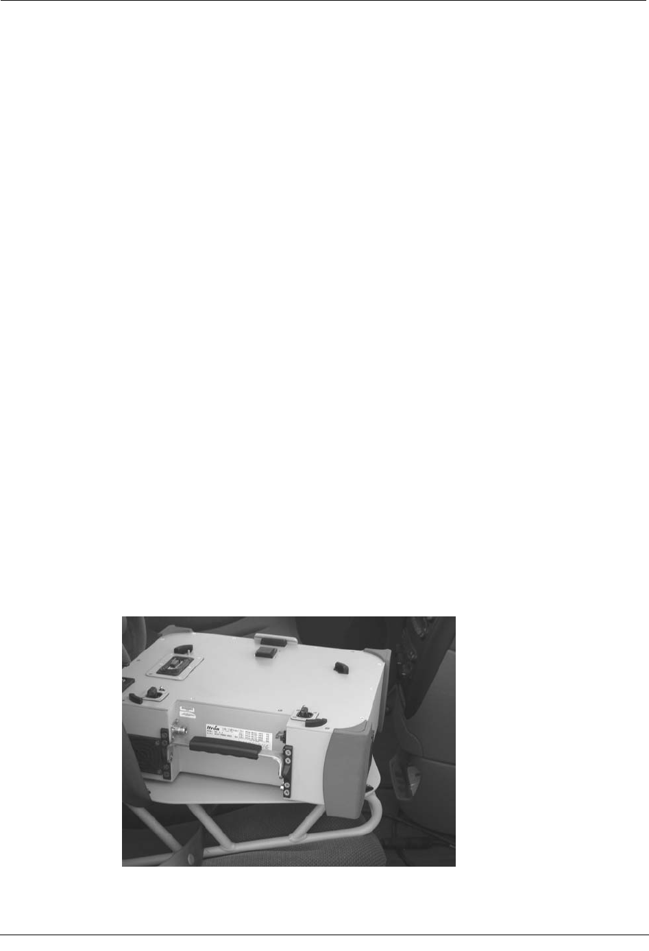
To attach the Mobile Collector to the Sled
1. Hold the Mobile Collector over the base and orient it so that the right rear corner faces
the passenger door.
2. Lower the Mobile Collector onto the sled and gently move it around until the center
pin on the base snaps into the center hole on the underside of the Mobile Collector.
Hardware Installation Guide 33
Chapter 2 Using the Mobile Collection 2.x System
3. While gently applying downward pressure, rotate the collector back and forth slightly
until the three pins on the base fit into the three matching holes on the underside of the
Mobile Collector.
4. Grip two corners of the Mobile Collector that are opposite each other diagonally and
rotate it counter-clockwise until you hear the locking pin snap into the underside of
the Mobile Collector.
When finished, the rear of the Mobile Collector should be flush with the side of the
base and its rear connectors should face the passenger door.
Connect the Antennas and Power Cables
The RF antenna, GPS antenna, and Mobile Collector power cable should be pre-installed in
the vehicle and routed to where the Mobile Collector will be installed.
The GPS system for version 2.x Mobile Collectors is an optional component that
is part of the Mapping system. If your installation does not include Mapping,
simply attach the RF antenna and the power cable in the procedure below; ignore
the steps related to the GPS antenna.
This section shows you how to connect the antennas and the power cable to the rear of the
Mobile Collector radio.
34 Hardware Installation Guide
Installing the Mobile Collection 2.x System
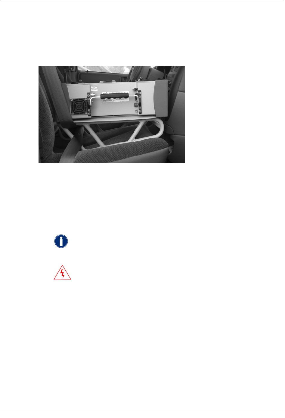
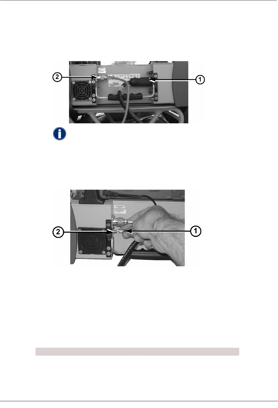
To connect the antennas and power cables
1. Plug the power cable (1) into the power connector on the Mobile Collector.
2. Attach the pre-wired RF antenna cable (2) and turn the knurled part of the antenna
cable clockwise until the cable is firmly attached.
If the power cable does not reach the Mobile Collector, use the optional
extension cable to extend the length (extension cables may be purchased
from Itron). Plug the power cable into one end of the extension cable and
plug the other end of the extension cable in to the Mobile Collector. Be sure
both ends snap into their respective connectors.
3. Attach the GPS cable to the connector. Both the end of the cable and the connector are
gold-plated for easy identification.
Attach the GoBook to the Mobile Collector 2.x
This section shows you how to connect both the GoBook MAX and GoBook III to the
Mobile Collector radio. The GoBook may be either attached directly to the Mobile
Collector radio or attached to a vehicle cradle mounted on a pedestal by the driver (for more
information, see GoBook Mounting Systems on page 32).
To attach the GoBook to the Mobile Collector, follow the steps in one of the following
sections:
GoBook MAX Procedures GoBook III Procedures
Attach the GoBook MAX to the Mobile
Collector on page 36 Attach the GoBook III to the Mobile
Collector on page 37
Attach the GoBook MAX to the Vehicle
Dock on page 38 Attach the GoBook III to the Vehicle
Dock on page 39
Hardware Installation Guide 35
Chapter 2 Using the Mobile Collection 2.x System
Attach the GoBook MAX to the Mobile Collector
Follow these steps to mount the GoBook MAX onto the Mobile Collector.
Before attempting to mount the GoBook onto the Mobile Collector, be sure to
unlock the locking mechanism.
To attach the GoBook MAX to the Mobile Collector
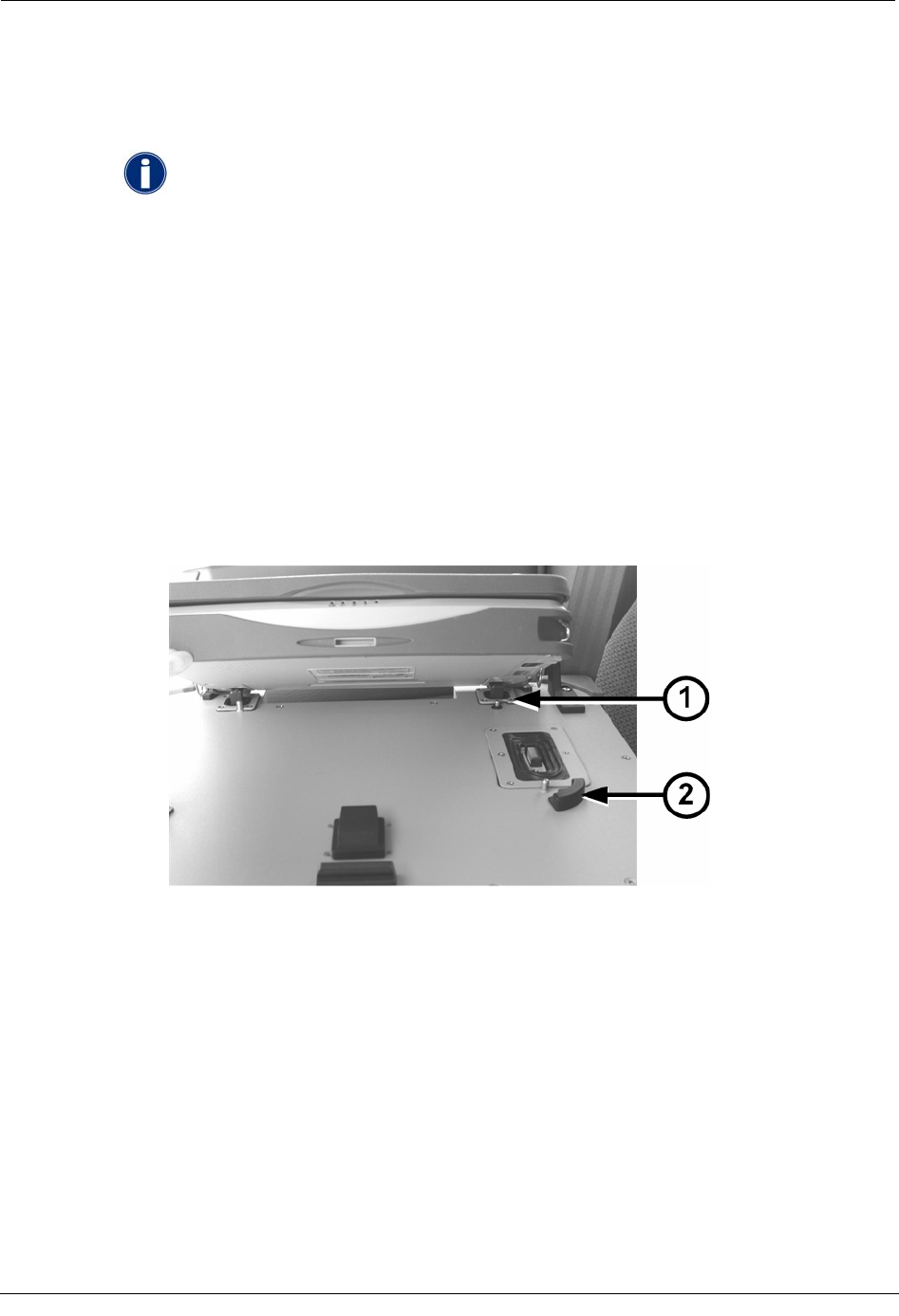
1. From the driver’s side of the vehicle, align the GoBook MAX with the four mounting
guides on top of the Mobile Collector.
2. Angle the top of the GoBook MAX towards the passenger door, as shown below, and
lower it so that the two rear connectors (1) on the Mobile Collector top fit into the
mating holes on the GoBook MAX underside.
3. Lower the GoBook MAX onto the Mobile Collector within the mounting guides (2)
until the underside of the GoBook MAX is flush with the top of the Mobile Collector.
If necessary, gently move the GoBook MAX slightly from side to side to ensure the
connectors on top of the Mobile Collector mate with those on the underside of the
GoBook MAX.
36 Hardware Installation Guide
Installing the Mobile Collection 2.x System
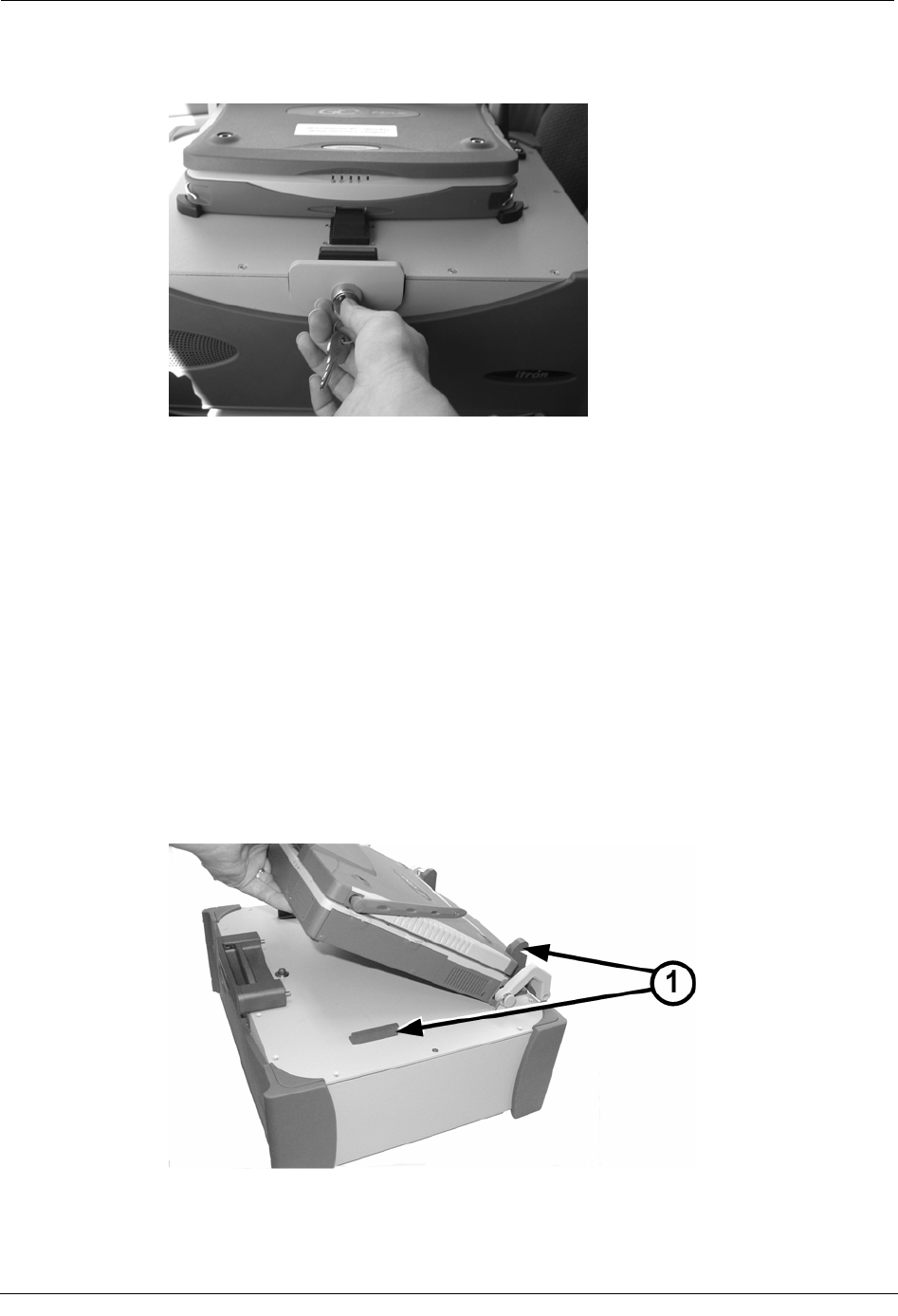
4. Insert the key into the mounting lock and press the locking mechanism so it engages
the GoBook MAX.
5. Turn the key clockwise to lock the GoBook MAX in place.
6. Remove the key from the lock so that it is not stolen or accidently broken.
7. Lift the GoBook MAX screen up and gently push it back so that it rests on the Mobile
Collector screen rest.
Attach the GoBook III to the Mobile Collector
Follow these steps to mount the GoBook III onto the Mobile Collector.
To attach the GoBook III to the Mobile Collector
1. From the driver’s side of the vehicle, align the GoBook III with the two mounting
guides (1) on top of the Mobile Collector.
2. Angle the GoBook III towards the passenger door, as shown below, and slide it under
the mounting guides (1) toward the back of the Mobile Collector.
3. Lower the GoBook III onto the Mobile Collector within the mounting guides until the
underside of the GoBook III is flush with the top of the Mobile Collector.
Hardware Installation Guide 37
Chapter 2 Using the Mobile Collection 2.x System
If necessary, gently move the GoBook III slightly from side to side to ensure the
connectors on top of the Mobile Collector mate with those on the underside of the
GoBook III.
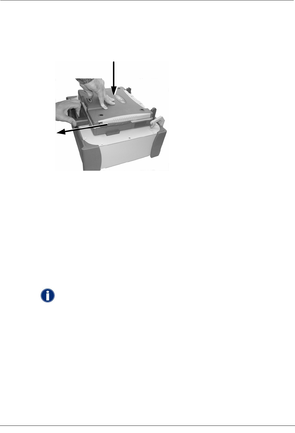
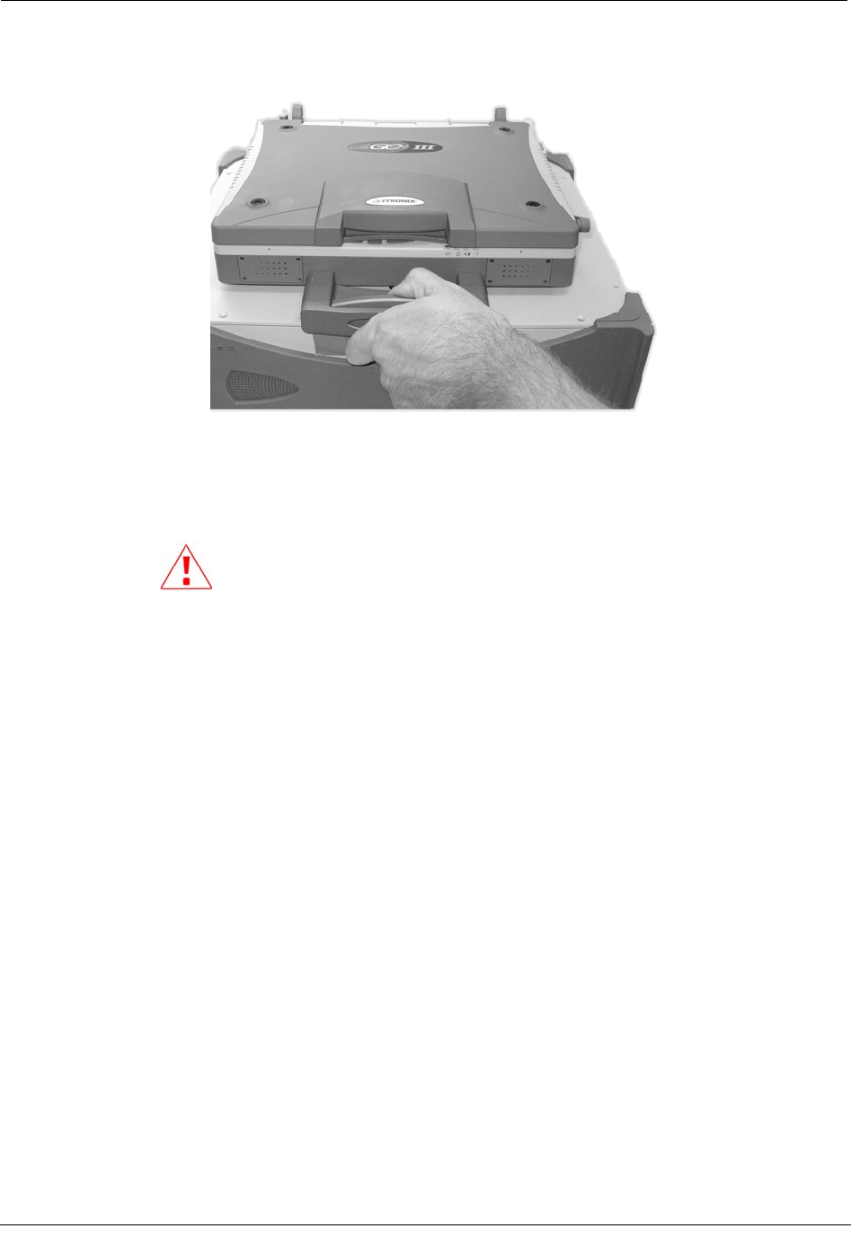
4. With one hand, pull on the locking mechanism to release it. With the other hand,
gently push down on the top of the GoBook III, as shown below.
5. Release the locking mechanism to lock the GoBook III in place.
6. Attach the necessary USB and power cables from the Mobile Collector to the GoBook
III.
7. Secure the USB cable in place by tightening the metal cable clip.
8. Lift the GoBook III screen up and gently push it back so that it rests on the Mobile
Collector screen rest.
Attach the GoBook MAX to the Vehicle Dock
As part of an optional remote installation, you may attach the GoBook MAX to a vehicle
dock on a pedestal near the driver. The vehicle dock should be pre-installed. Refer to the
Itronix Vehicle Cradle Installation Guide for detailed instructions.
The Itronix documentation refers to the laptop receptacle as a cradle; Itron uses
the term dock to identify this piece of equipment. The term dock is used repeatedly
throughout this manual; however, dock and cradle are interchangeable.
To attach the GoBook MAX to the vehicle dock
1. Angle the top of the GoBook MAX and center on the vehicle dock mounting guides,
then lower it so that the two rear locking mechanisms on the vehicle dock top fit into
the mating holes on the GoBook MAX underside.
2. Lower the GoBook MAX onto the vehicle dock within the mounting guides until the
underside of the GoBook MAX is flush with the top of the vehicle dock.
3. Insert the key into the mounting lock.
4. Press the locking mechanism so it engages the GoBook MAX.
38 Hardware Installation Guide
Installing the Mobile Collection 2.x System
5. Turn the key clockwise to lock the GoBook MAX in place.
Remove the key from the lock so that it is not accidently broken or stolen.
6. Plug the vehicle dock cable into a vehicle dock USB port. Two USB ports are located
on the back of the vehicle dock.
7. Plug the vehicle dock cable into the Mobile Collector radio by pulling the SMA
connector sleeve back, plugging the connector in to the Mobile Collector as shown,
and releasing the sleeve.
Attach the GoBook III to the Vehicle Dock
As part of an optional remote installation, you may attach the GoBook III to a vehicle cradle
on a pedestal near the driver. The vehicle cradle should be pre-installed. Refer to the Itronix
Vehicle Cradle Installation Guide for detailed instructions.
To attach the GoBook III to the vehicle dock
1. Lower the GoBook III onto the vehicle dock. Be sure to align it within the front and
read guides on the dock. The front of the laptop should face the locking mechanism on
the front of the dock.
2. Push in the handle on the front of the dock to engage the locking mechanism and
secure the GoBook to the dock.
3. Push in the keyed part of the locking mechanism to further lock it and prevent theft of
the GoBook.
4. Plug one end of the USB cable into one of the two available ports on the back of the
vehicle dock. The port uses a standard USB connector.
Hardware Installation Guide 39
Chapter 2 Using the Mobile Collection 2.x System
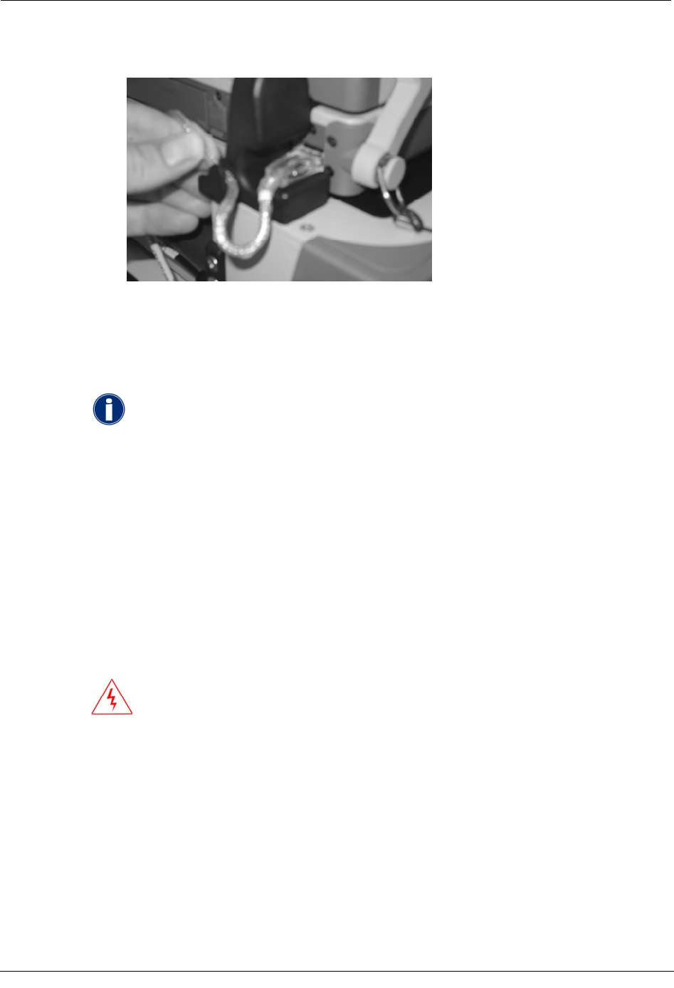
5. Plug the vehicle dock USB cable into the USB port on the Mobile Collector by pulling
the SMA connector sleeve back, plugging the connector in to the Mobile Collector,
and releasing the sleeve. This port uses an SMA connector.
Connect the GoBook III Power Supply and USB Cable
The GoBook III receives power from the Mobile Collector radio itself, through a simple
power cable connection. In versions of the Mobile Collection system that use a GoBook
MAX, the power and data connections are integrated into the top of the Mobile Collector
radio.
For the GoBook III, additional cables must be attached to provide the laptop with power and
a data connection. The USB cable is used to provide data collected by the Mobile Collector
radio to the Mobile Interface application running on the GoBook III.
To connect the GoBook III power supply and USB cable
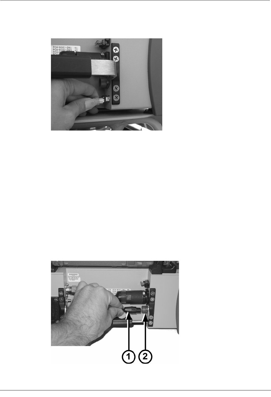
1. Attach the end of the GoBook III power cable (1) to the blue connector on the back of
the Mobile Collector radio (2); this connector is located beneath the main power
supply.
40 Hardware Installation Guide
Installing the Mobile Collection 2.x System
2. Attach the other end of the power cable to the connector on the back of the GoBook
III.
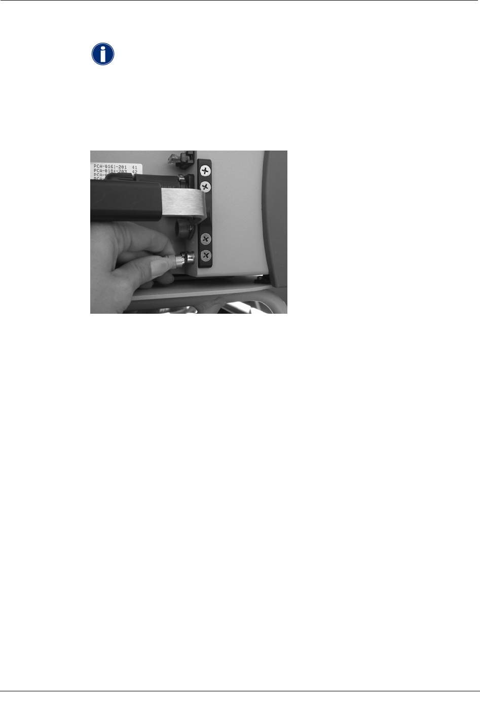
3. Plug the USB cable into the Mobile Collector radio by pulling the SMA connector
sleeve back, plugging the connector in to the Mobile Collector as shown, and
releasing the sleeve.
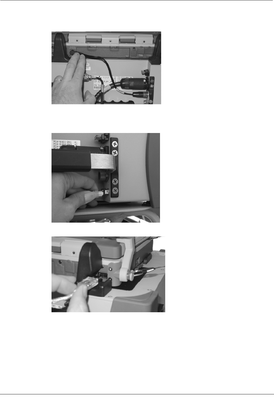
4. Connect the USB cable to the back of the GoBook III as shown below.
5. Route the USB cable through the channel on the back of the Mobile Collector radio
mounting guide. Press the cable down into the channel to make sure it is secure.
Hardware Installation Guide 41
Chapter 2 Using the Mobile Collection 2.x System
This ensures data communication between the GoBook III and the Mobile Collector
radio while you are driving a route.
Using the Flash Card in Mobile Collector 2.x Systems
You can import route files to the Mobile Interface database and export the collected data
using a removable flash card in the Mobile Collector flash card reader.
The default drive letter for the flash card reader will vary, depending
on the type of GoBook used in your system configuration.
• GoBook MAX When using the GoBook MAX, the card reader
defaults to drive F:.
• GoBook III When using the GoBook III (which may include an
optional 3-slot external reader), the card reader can be any of the
following drives: G:, H:, and I:. The actual letter used will vary
depending on when various peripherals are connected to the
system. Always ensure you are accessing the proper drive.
Insert the Flash Card
Follow these steps to insert the flash card.
WARNING! If you do not hold the flash card correctly, the flash
card will not insert into the reader. Forcing the flash card into the
reader may damage the reader by bending the connector pins.
42 Hardware Installation Guide
Installing the Mobile Collection 2.x System
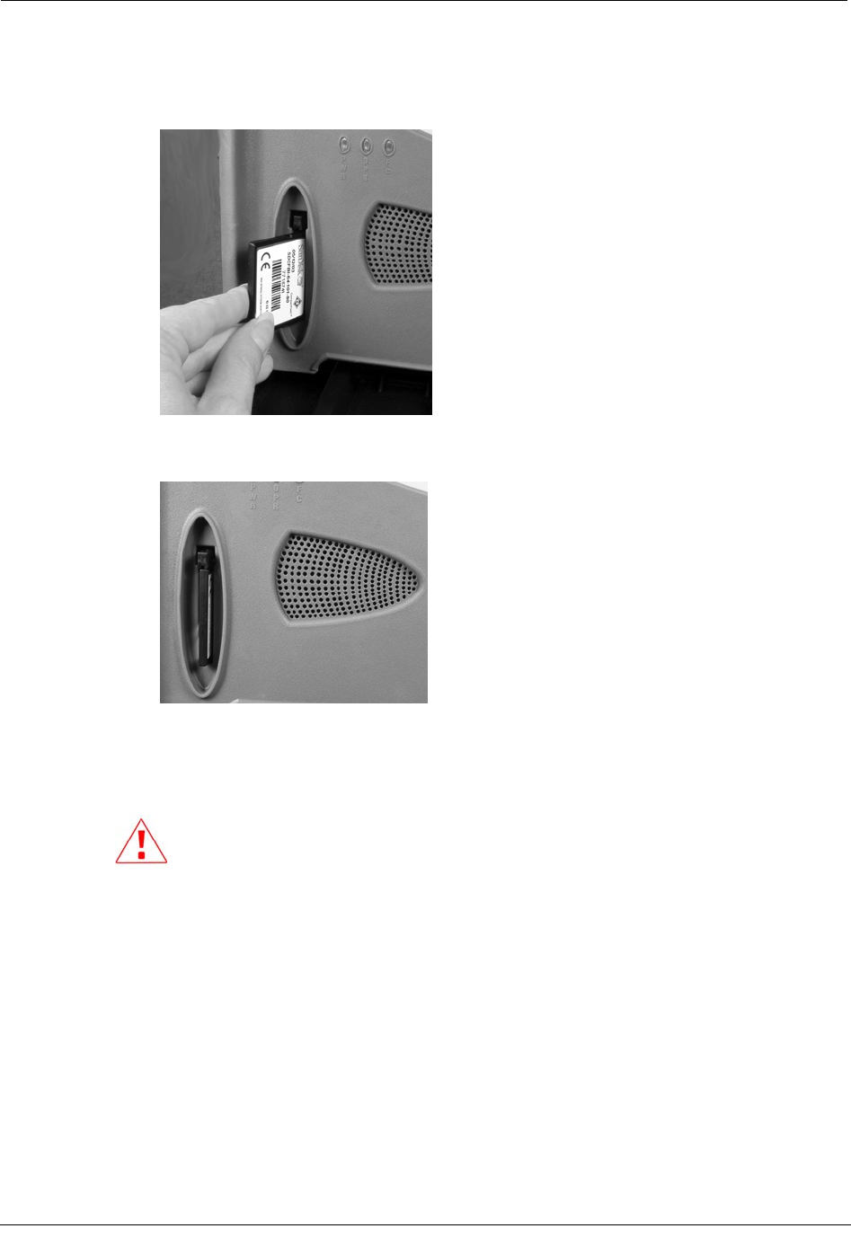
To insert the flash card
1. Hold the flash card as shown to insert it into the Mobile Collector Flash Card Reader.
2. Insert the card in the flash card reader slot and press it in until it is firmly in place and
the eject button pops out.
Remove the Flash Card
Follow these steps to remove the flash card.
Before removing the flash card, shut down the GoBook. Failure to do so could
result in data loss on your flash card.
To remove the flash card
1. Shut down the GoBook.
2. Press the eject button on the flash card reader.
3. Gently pull the flash card out of the flash card reader slot.
Hardware Installation Guide 43
Chapter 2 Using the Mobile Collection 2.x System
Removing the Mobile Collection 2.x System
At some point, you may need to remove the Mobile Collection system from the vehicle.
Perform the following tasks to remove the Mobile Collection system.
Before removing any Mobile Collection system components be sure to stop the
Mobile Interface and shut down the GoBook.
Unlock and Remove the GoBook
Follow these steps to remove the GoBook from the Mobile Collector or vehicle cradle. The
following procedure can be used with either the GoBook MAX or GoBook III.
To unlock and remove the GoBook
1. Shut down any open applications and then shut down the GoBook.
2. Close the GoBook screen.
3. Disengage the GoBook locking mechanism:
• GoBook MAX Insert the key in the locking mechanism and turn it counter-
clockwise. Pull the key and the mounting lock towards you so the locking
mechanism is disengaged from the GoBook.
-> If unlocking the GoBook MAX from the vehicle cradle, push in underneath
the locking mechanism and then pull the mechanism out.
44 Hardware Installation Guide
Removing the Mobile Collection 2.x System
• GoBook III Disconnect any cables from the back of the GoBook III. Pull the
locking mechanism out, away from the GoBook III.
-> If unlocking the GoBook III from the vehicle dock, push up and in on the
underside of the locking mechanism, and then pull the mechanism out to release
it.
4. Gently lift the GoBook up and away from the Mobile Collector radio or vehicle dock.
CAUTION If you accidently disconnect the GoBook from the MC3
radio before shutting down Windows, the following message appears:
Unsafe Removal of Device
Before clicking OK, clear the ShowUnplug/Eject icon on the Taskbar
box. If you do not clear this box, you will not be able to properly shut
down the system in the future.
Disconnect the Cables
Unplug the cables from the Mobile Collector and leave them for the next installation of a
Mobile Collection system, if desired.
To disconnect the cables
1. Complete Unlock and Remove the GoBook on page 44.
2. Unplug the cables from the Mobile Collector. This includes the USB cable, power
cable, and any antenna cables.
Remove the Mobile Collector from the Sled
When you attached the Mobile Collector to the sled, a locking pin snapped into the
underside of the Mobile Collector. To remove the Mobile Collector, you must reach
underneath the top of the sled and pull down on the locking pin while rotating the Mobile
Collector slightly.
Hardware Installation Guide 45

Chapter 2 Using the Mobile Collection 2.x System
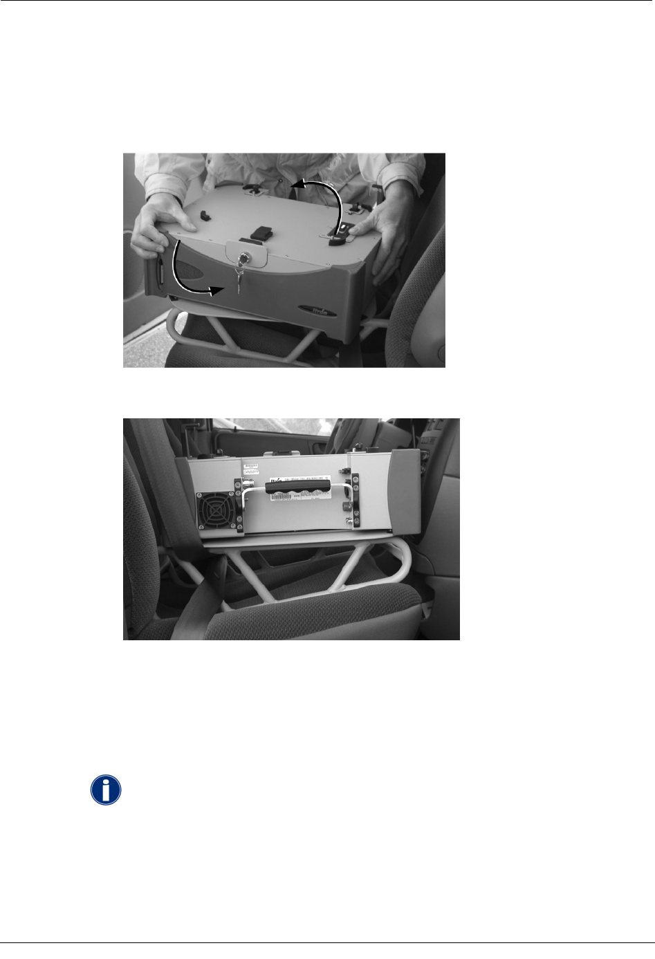
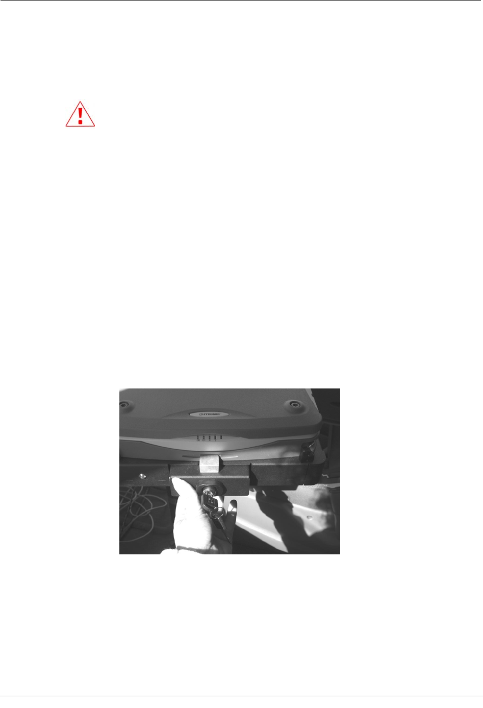
To remove the Mobile Collector from the sled
1. From the passenger side of the vehicle, reach underneath the top of the base and locate
the locking pin knob.
2. Use one hand to pull the knob down, and use the other hand to push a corner of the
Mobile Collector in a clockwise direction.
3. Continue pulling the knob down and pushing until the pin can no longer snap into the
underside of the Mobile Collector.
4. Grip two corners of the Mobile Collector that are opposite each other diagonally and
rotate it clockwise until you cannot rotate it further.
The right rear corner of the Mobile Collector faces the passenger-side door when the
Mobile Collector cannot be rotated further.
5. Lift the Mobile Collector off the base.
6. Unfasten the seat belt and pretensioner and lift the base off the seat.
46 Hardware Installation Guide
CHAPTER 3
Using the EkaNet System
The EkaNetTM system is an optional component that can be used with the Mobile Collection
system. An additional antenna and radio are used to communicate with Eka-equipped
endpoints in the field to enable mobile demand reset functionality.
This chapter shows you how to install the EkaNet hardware components in a
vehicle and then connect them to the Mobile Collection system. In order to use the
mobile demand functionality in the Mobile Interface, a separate software
installation must be performed on the GoBook. See your system administrator for
more information.
EkaNet System for Mobile Demand Reset
The EkaNet radio is only required if you are using Itron Advanced Drive-by AMR (mobile
demand reset) for electric meters. It is ordered separately from the Itron Mobile Collection
system.
WARNING! Keep at least two feet away from the EkaNet antenna when it is
transmitting.
The EkaNet antenna should be at least four feet away from the regular Mobile Collection
RF antenna to prevent interference.
For more information about the EkaNet system, see the:
• EkaNet Mobile Collector Hardware Installation Manual (document number
10250)
• EkaNet Mobile Collection Software Manual (document number 10223)
By default, these documents are stored in the following location:
C:\Program Files\Eka\EkaNet Mobile\doc
EkaNet Compatibility
The following table lists the versions of Mobile Collection hardware (radio and laptop) that
are compatible with the EkaNet system.
Mobile Collection v3.0 software is required for the EkaNet system. Although
older versions of hardware can support the system, you must use v3.0 software.
Laptop Radio Version EkaNet Compatible?
GoBook MAX 2.0 No
Hardware Installation Guide 47
Chapter 3 Using the EkaNet System
Laptop Radio Version EkaNet Compatible?
GoBook MAX MC3 No
GoBook III 2.5 Yes
GoBook III MC3 Yes
GoBook XR-1 2.5 Yes
GoBook XR-1 MC3 Yes
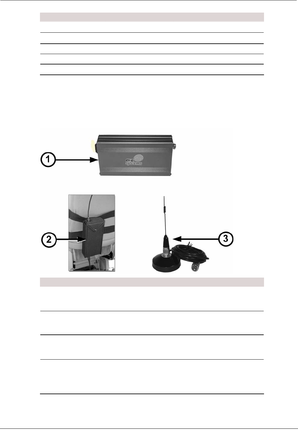
About the EkaNet Components
The following components are a part of the optional EkaNet system. These components
need to be installed in the vehicle.
ID Item Description
1 EkaNet radio
Routes data received by the antenna to the laptop
running the Mobile Interface software, with EkaNet
software enabled.
2 Radio pouch
Secures the radio in the vehicle. The pouch connects to
the MC3 radio harness.
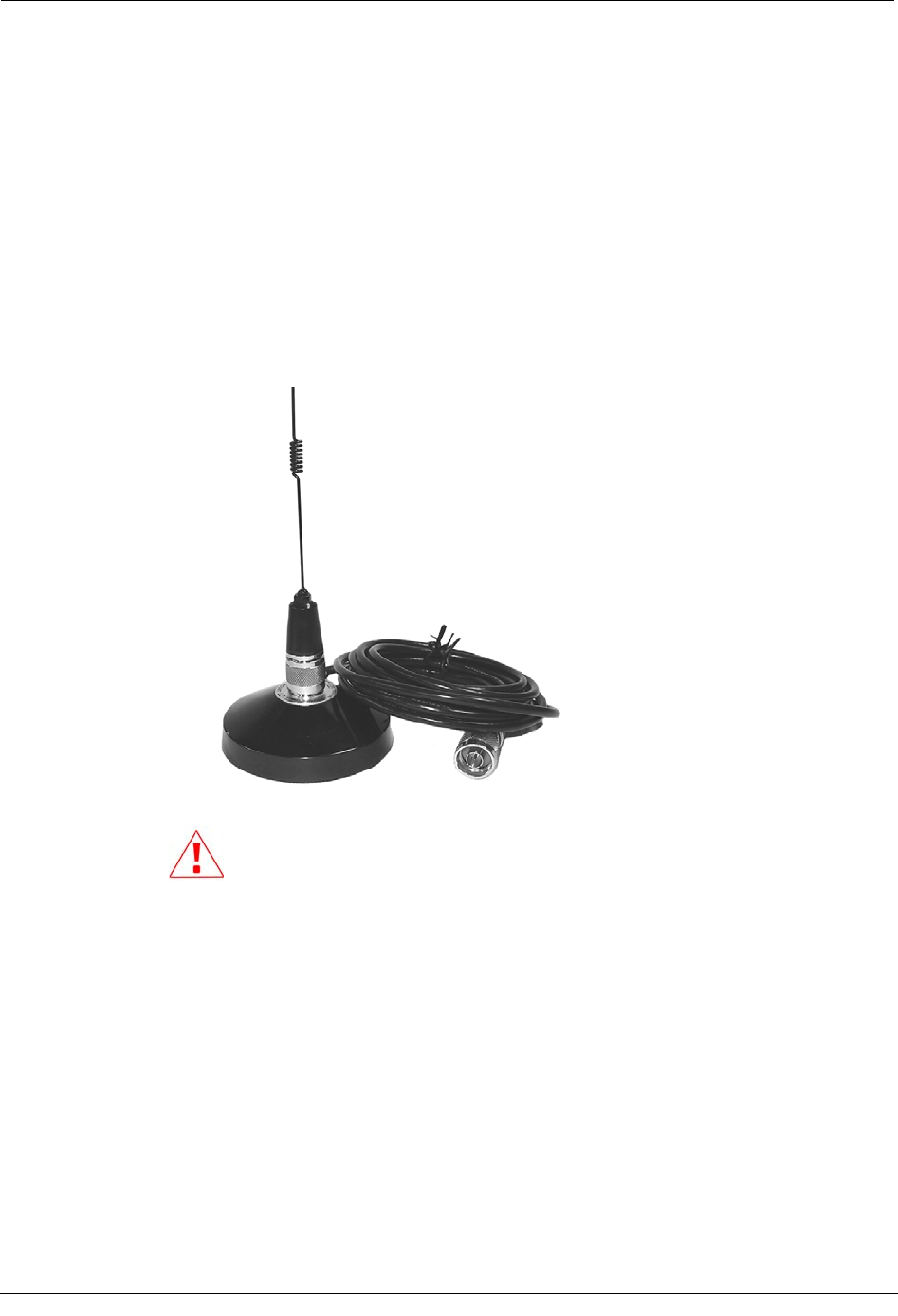
3 EkaNet antenna
Receives data from Eka-enabled endpoints in the field.
The antenna should be installed 4 feet away from the
main Mobile Collection RF antenna.
* Not
Pictured Cables A power cable from the Mobile Collection junction box
supplies the radio with power.
A serial cable from the radio to the laptop transfers
data.
48 Hardware Installation Guide
Installing the EkaNet System
Installing the EkaNet System
Follow the steps below to connect the EkaNet system.
To connect the EkaNet system
1. Attach the external EkaNet antenna to the top of the vehicle. It should be placed at
least four (4) feet away from the main Mobile Collector RF antenna to prevent
interference.
This antenna uses a powerful magnet to attach to the vehicle.
2.
Using a magnetic-mount antenna on a fiberglass-roofed vehicle is not
recommended. The antenna may come loose during transit and be
damaged. It could also be a hazard to others if it falls of the roof of a moving
vehicle.
Hardware Installation Guide 49
Chapter 3 Using the EkaNet System
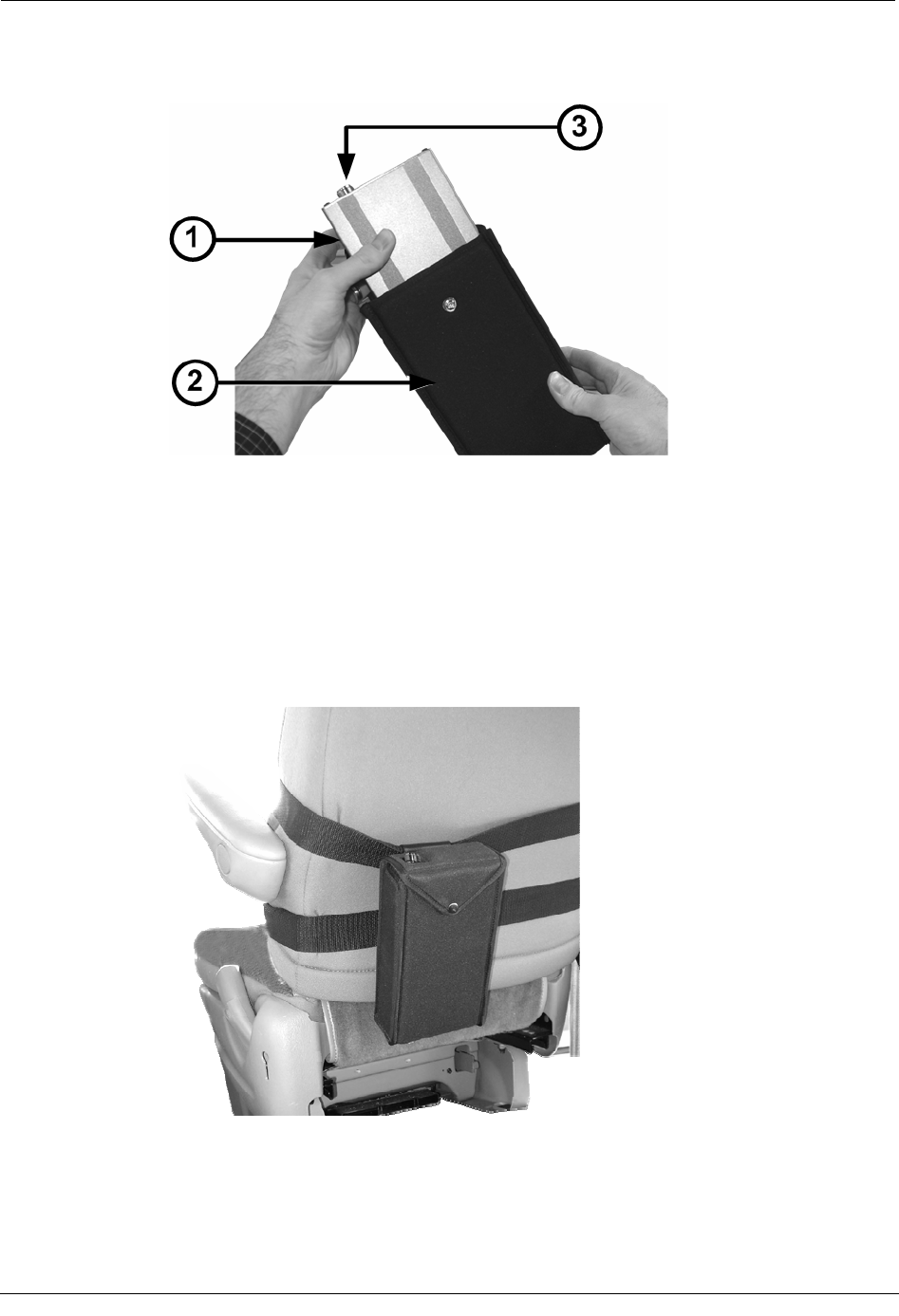
3. Insert the EkaNet radio (1) into the pouch (2). The antenna connector (3) must face
the top of the pouch.
4. Close the pouch flap over the radio and snap it shut to secure the EkaNet radio.
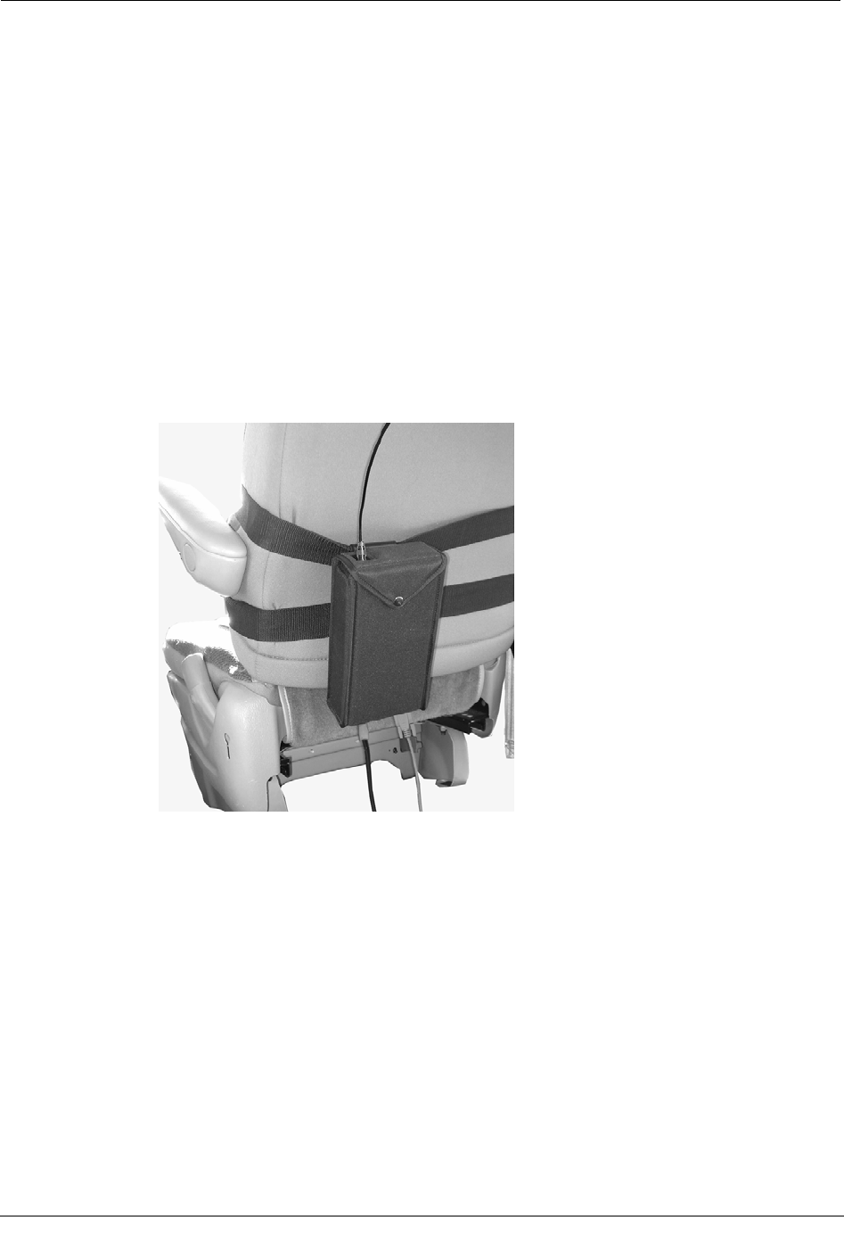
5. Clip the EkaNet pouch to a harness strap on the back of the seat where the Mobile
Collection system is installed.
• If you are using an MC3 system, clip the pouch to one of the straps that secure
the MC3 radio to the seat. This setup is shown in the picture below.
• If you are using a Mobile Collection 2.x system, a black fabric strap is included
with the EkaNet pouch. Route and buckle this strap horizontally around the
passenger seat, and then clip the pouch to it.
50 Hardware Installation Guide
Installing the EkaNet System
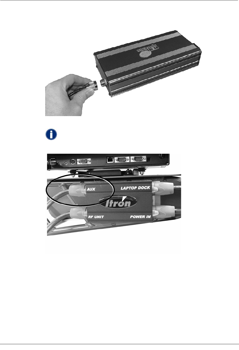
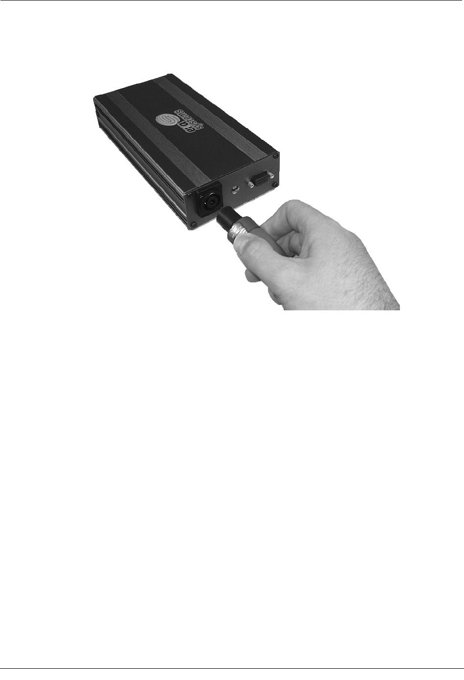
6. Connect the EkaNet antenna cable to the top of the radio. Note that in the following
example, the pouch and vehicle have been removed for emphasis.
7. Connect the EkaNet power cable to the AUX port on the junction box in your vehicle.
If you do not have a junction box in your installation, power will need to
be hard-wired from the vehicle's battery to the radio; see your system
administrator for assistance.
Hardware Installation Guide 51
Chapter 3 Using the EkaNet System
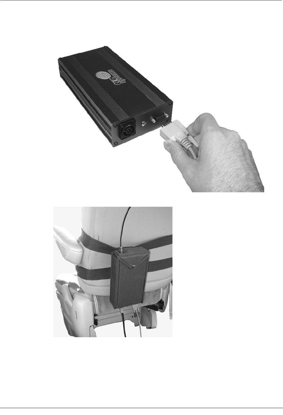
8. Connect the other end of the power cable to the port on the bottom of the radio. Note
that in the following example, the pouch, vehicle, and other cables have been removed
for emphasis.
9. Connect the serial cable to comm 1 serial port on the laptop (or dock); this is the end
without pins. Be sure to securely connect the cable.
• For the GoBook XR-1, the serial port is located on the right-hand side of the
laptop (9-pin male connector).
• For the GoBook III, the serial port is located on the back of the laptop (9-pin
male connector).
52 Hardware Installation Guide
Installing the EkaNet System
10. Connect the other end of the serial cable to the bottom of the EkaNet radio; this is the
end with pins. Be sure to securely connect the cable. Note that in the following
example, the pouch, vehicle, and other cables have been removed for emphasis.
When you have finished, the system should look similar to the example below.
Hardware Installation Guide 53
Chapter 3 Using the EkaNet System
Removing the EkaNet System
When you have finished collecting data with the EkaNet system, you can remove it from
your vehicle.
To remove the EkaNet system
1. Ensure that the vehicle is turned off.
2. Ensure that the GoBook has completed processing reads and is properly shut down.
3. Disconnect the following from the EkaNet radio inside the vehicle:
• Antenna (connected to the top of the radio and pouch).
• Power and serial communications cables (located on the bottom of the radio
and pouch).
4. Remove the radio and pouch from the vehicle. You can either:
• Unclip the pouch from the strap it is attached to. Then unbuckle the strap and
store it with with EkaNet radio and pouch.
54 Hardware Installation Guide
Removing the EkaNet System
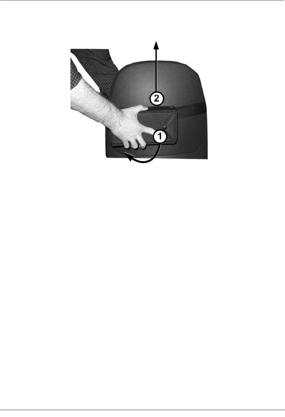
• Leave the clip attached to the strap, but remove the pouch from the clip
assembly. To do so, rotate the pouch clockwise 90-degrees (1) and then pull it
straight up (2). The clip and strap can remain in the vehicle.
Hardware Installation Guide 55

Chapter 3 Using the EkaNet System
56 Hardware Installation Guide

CHAPTER 4
System Maintenance
This chapter introduces you to some of the basic maintenance procedures that should be
performed regularly to ensure optimal performance of your Mobile Collection system.
For more information, see:
• MC3 Systems
• Mobile Collection 2.x Systems
• GoBook Maintenance
• Antenna Maintenance
RF Antenna Maintenance
The following procedures should be followed to ensure that the RF omni-mount antenna for
your Mobile Collection system is operating properly.
Cleaning
In order to maintain both the performance and the appearance of your omni-mount RF
antenna, regular cleaning is recommended. Clean the antenna in the same manner as your
vehicle. Applying a quality car wax to the antenna and base will help protect the finish and
extend the life of the antenna.
Replacing Gaskets
To maintain the integrity and performance of the antenna, Itron recommends that you
replace the gasket located in the antenna base at least every year. Replacement gaskets (part
number MSE-0210-001, in a packet of six) are available from Itron; contact Customer
Support (1-800-635-8725) for more information.
You should also inspect the gasket regularly to verify that it is intact, free from debris, and
properly seals the antenna and base.
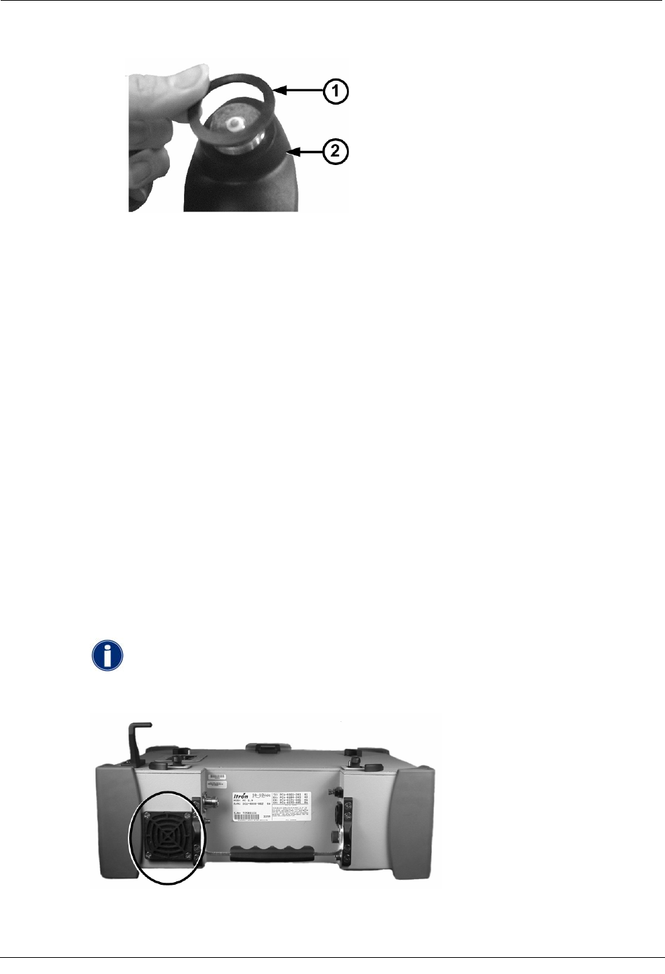
To replace the antenna gasket
1. Turn the antenna counter-clockwise to remove it from the base.
Hardware Installation Guide 57
Chapter 4 System Maintenance
2. Remove the gasket (1) from the base (2).
3. Place a new gasket on the base. Push it firmly into place. Ensure that it is level on the
antenna base; if it is not level, it could be pinched into the base and damaged when the
antenna is reconnected.
4. Reconnect the antenna to the base by turning it clockwise until it is firmly seated on
the base.
2.x System Maintenance
In addition to the antenna maintenance described earlier, the following tasks should be
performed regularly to keep your Mobile Collection 2.x system operating at peak
performance.
Inspecting and Replacing Filters
The Mobile Collector has two internal fans that circulate air through its components to cool
them. One fan draws air in from the side of the Mobile Collector, while the second fan
blows the air out the rear.
Each fan has a filter accessible externally that requires periodic replacement, depending on
the environment in which the Mobile Collector is operated. To replace the filter, pull the fan
cover off, replace the filter, and snap the fan cover back on.
Inspect the filters regularly and replace them when they become visibly
dirty. Contact an Itron customer service representative to order
replacement filters.
58 Hardware Installation Guide

Service Bulletins
Service Bulletins
The following information is for customers with legacy Mobile Collection systems in their
deployments.
The Service Bulletins listed below should have already been shipped to you, along with any
required hardware updates, but are included here as a reminder and to help you identify any
system components that may need updating.
Mobile Collection 2.5 / GoBook III Power Plug Issue
(Bulletin Issued June 5th, 2006)
In the interest of continuous improvement, Itron has incorporated a reliability upgrade to
your Mobile Collector. The present CBA-0259-002 cable that provides power from the RF
unit to the GoBook III has the conductor exposed on the right angle plug that is inserted into
the GoBook III. With the end of the plug exposed, it is possible to short the exposed tip on
the metal RF chassis. This only happens when power is supplied to the RF unit before this
connection is made between the RF unit and GoBook III. The result of this shorting
condition is damage to a transistor on the power board inside of the RF unit, which requires
your RF unit to be returned to Itron for repair.
To alleviate this problem, we are replacing the existing CBA-0259-002 power plug with the
enclosed CBA-0305-002. CBA-0305-002 has an insulated tip to prevent shorting on the
chassis. Please replace the existing power cable with CBA-0305-002 as soon as possible and
scrap the CBA-0259-002. We also recommend that you always connect the cable from the
RF unit to the GoBook III before you apply power to RF unit.
This improvement is also being made on all new Mobile Collection 2.5 systems being
shipped and all Mobile Collectors when they are returned for service.
If you have any questions, please contact Itron Support at 1-800-635-8725.
Mobile Collector 2.x Power Adapter
(Bulletin Issued September 8th, 2006)
In the interest of continuous improvement, Itron has incorporated a reliability upgrade in
your Mobile Collector. Reliability of the existing power connector has become the number
one cause of Mobile Collector returns during the past year. As a result, we are replacing the
existing power connector with a new power connector that has tested to have improved
reliability and durability.
Along with the new power connector in your RF unit, we have included a new power cable
with new power connectors. It is imperative that you use the new power cable with your RF
unit. The old power cable will not lock into place with the new power connector.
Hardware Installation Guide 59
Chapter 4 System Maintenance
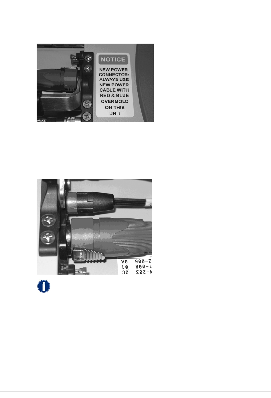
The new power cable was designed to be easily distinguishable from the existing power
cable by placing a red and blue overmold on the connectors. A notice label was placed on
the chassis of the RF unit to remind you of this requirement.
The operation of the new power cable is slightly different from the previous power
connector. To engage the new power connector, align the connector tab with the connector
slot on the RF unit, insert the connector and then rotate clockwise 45 degrees. To disengage
the unit, pull back the locking tab on the cable connector and then rotate the connector 45
degrees counterclockwise. Notice labels were placed on both ends of your power cable to
remind you how to disengage the new power connector.
If you presently utilize a power cable that plugs into the cigarette
lighter, you will need to contact Itron Support at 1-800-635-8725 to
request a replacement cable. You will be required to send your old
cable in as an exchange. It should be noted that Itron does not
recommend the cigarette lighter adapter configuration except for
emergency use.
This change to the new power connector will be incorporated on all new MC2.5 being
shipped and all Mobile Collectors when they are returned for service.
If you have any questions, please contact Itron Support at 1-800-635-8725.
60 Hardware Installation Guide

Service Bulletins
Hardware Installation Guide 61