Itron DCU5310U AMR Transceiver Device User Manual Installation Guide
Itron, Inc. AMR Transceiver Device Installation Guide
UserManual.wiki
>
Itron
>
DCU5310U User Manual
>
Users Manual 1
Contents
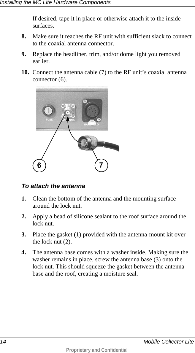
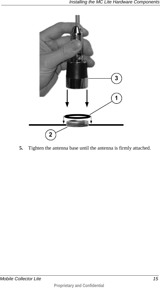
1.
Users Manual 1
2.
Users Manual 2
Users Manual 1
Navigation menu
Upload a User Manual
Namespaces
Wiki Guide
HTML
PDF
Info
Views
User Manual
Discussion / Help
Navigation