Itron DCU5310U AMR Transceiver Device User Manual Installation Guide
Itron, Inc. AMR Transceiver Device Installation Guide
Itron >
Contents
- 1. Users Manual 1
- 2. Users Manual 2
Users Manual 1

Mobile Collector Lite Error! No text of specified style in document. i
Proprietary and Confidential

Contents
ii Mobile Collector Lite
Proprietary and Confidential
Contents
Copyright ...................................................................................................................... C
Introduction .................................................................................................................. 1
Unpacking the MC Lite Hardware ............................................................................ 2
RF Unit Features ...................................................................................................... 3
The LED Status Indicator ......................................................................................... 3
Installing the MC Lite Hardware Components .......................................................... 4
Installing the Antenna Mount and Antenna ............................................................ 12

Contents
Mobile Collector Lite iii
Proprietary and Confidential
Copyright
Identification
Mobile Collector Lite Installation Guide
06/16/2010 TDC-0730-005
Copyright
© 2007-2010 Itron, Inc. All rights reserved.
Confidentiality Notice
The information contained herein is proprietary and confidential and is being provided subject to the condition that (i) it be
held in confidence except to the extent required otherwise by law and (ii) it will be used only for the purposes described
herein. Any third party that is given access to this information shall be similarly bound in writing.
Trademark Notice
Itron is a registered trademark of Itron, Inc.
All other product names and logos in this documentation are used for identification purposes only and may be trademarks or
registered trademarks of their respective companies.
Suggestions
If you have comments or suggestions on how we may improve this documentation, send them to
TechnicalCommunicationsManager@itron.com
If you have questions or comments about the software or hardware product, contact Itron Technical Support:
Compliance
This device complies with Part 15 of the FCC Rules. These limits are designed to provide reasonable protection against
harmful interference in a residential installation. Operation is subject to the following two conditions:
• This device may not cause harmful interference.
• This device must accept any interference that may cause undesirable operation.
This device must be permanently mounted such that it retains a distance of 55 centimeters (21.7 inches) from all persons in
order to comply with FCC RF exposure levels.
USA, FCC Class B - Part 15
This equipment has been tested and found to comply with the limits for a Class B digital device, pursuant to Part 15 of the
FCC Rules. These limits are designed to provide reasonable protection against harmful interference in a residential
installation. This equipment generates, uses, and can radiate radio frequency energy and, if not installed and used in
accordance with the instructions, may cause harmful interference to radio communications. However, there is no guarantee
that interference will not occur in a particular installation.
If this equipment does cause harmful interference to radio or television reception, which can be determined by turning the
equipment off and on, the user is encouraged to try to correct the interference by one or more of the following measures:
• Reorient or relocate the receiving antenna.
• Increase the separation between the equipment and receiver.
• Connect the equipment into an outlet on a circuit different from that to which the receiver is connected.
• Consult the dealer or an experienced radio or TV technician for help.
This equipment has been tested and found to comply with the limits, pursuant to Part 15 of the FCC Rules. These limits are
designed to provide reasonable protection against harmful interference in a residential installation. Operation is subject to
the following conditions:
• This device may not cause interference.
• This device must accept any interference that may cause undesired operation of the device.

Contents
iv Mobile Collector Lite
Proprietary and Confidential
CANADA, DOC ICES-003
This digital apparatus does not exceed the class B limits for radio noise emissions from digital apparatus set out in the Radio
Interference Regulations of the Canadian Department of Communications, standard ICES-003.
This equipment complies with policies RSS-210 and RSS-GEN of the Industry Canada rules.
Operation is subject to the following two conditions: (1) this device may not cause interference, and (2) this device must
accept any interference, including interference that may cause undesired operation of the device.
Note Modifications to the device or its antenna not expressly approved by the party responsible for compliance could void
the user’s authority to operate the device.
Avis de conformite aux normes du Ministere des Communications du Canada.
Le present appareil numerique n emet pas de bruits radioelectriques depassant les limites applicable aux appareils
numeriques classe B prescrites dans le Reglement sur le brouillage radioelectrique edicte par le Ministere des
Communications du Canada, NMB-003.
Disclaimer
RF EXPOSURE
To comply with FCC requirements, maintain a separation distance of at least 55.0 centimetres between the antenna and all
persons.
ELECTROMAGNETIC COMPATIBILITY
Use only approved accessories with this equipment. In general all cables must be high quality, shielded, correctly
terminated, and normally restricted to 2 meters in length. The Mobile Collector Lite employs special provisions to avoid radio
interference and should not be altered or substituted.
Unapproved modifications or operation beyond or in conflict with these instructions for use, may void authorization by the
authorities to operate the equipment.
Warning Do not visually monitor or physically
adjust the Mobile Collector Lite system while
driving. While driving, rely on the beeps produced
when meter data is collected to indicate proper
system operation. Visually monitoring or adjusting
the Mobile Collection system while driving will
divert your attention from your safe driving
responsibilities. Attention to driving is your primary
responsibility, along with following all the
applicable driving regulations.
Contact
• Internet: www.itron.com
• E-mail: support@itron.com
• Phone: 1 877 487 6602

Mobile Collector Lite 1
Proprietary and Confidential
Introduction
This document contains information to help you install your Mobile
Collector Lite (MC Lite) RF unit (radio) and handheld meter data
collection device (handheld) in a vehicle.
MC Lite is supported by Itron’s Field Collection System and Itron’s
MV-RS meter data collection system. For information on how to run
MC Lite from these applications, see the Field Collection System
Handheld User Guide or the MV-RS CE Handheld Guide, or the
handheld online help for either application.
The following documentation is included with the MC Lite
installation kit, some which is based on the handheld used.
• MC Lite Quick Start Guide, which provides at-a-glance
information on how to get started with Mobile Collector Lite.
• FC200 Vehicle Dock User Guide, which contains instructions for
using and maintaining the vehicle dock for the FC200 handheld.
• FC300 Docks Quick Reference, which explains how to set up the
FC300’s desk dock, multi-dock, and vehicle dock.
For further, detailed information, consult the following related
documents, which are available from Itron’s customer support Web
site (http://support.itron.com).
• FC200 Series Getting Started Guide, which contains instructions
for using and maintaining the FC200 handheld meter data
collector.
• FC300 Getting Started Guide, which contains instructions for
using and maintaining the FC300 handheld meter data collector.
• FC300 Handheld Computer Quick Reference, which explains
how to set up the handheld and prepare it for use with Itron’s
Field Collection System and MV-RS meter data collection
applications. This quick reference is also included in the kit
containing the FC300 handheld.
• FC300 Docks User Guide, which contains instructions for using
and maintaining the FC300 vehicle dock.
For instructions on how to register and download documentation
from the customer support Web site, see the MC Lite Quick Start
Guide.

Introduction
2 Mobile Collector Lite
Proprietary and Confidential
Unpacking the MC Lite Hardware
Your MC Lite installation package should include these items:
• 1 MC Lite RF unit with safety harness
• 1 RF unit vehicle mount
• 2 bench seat straps
• 1 handheld interface cable
• For permanent wiring
• 1 power cable with fuse block connected power cable
• 1 antenna and permanent mount base with attached antenna
cable
• 1 power extension cable for connecting to MC Lite RF unit, 8
feet
• For portable wiring
• 1 12 volt DC power supply cable
• 1 antenna and magnetic mount base with attached antenna
cable
• 1 handheld vehicle dock
• 1 Ram Mount double-socket connector, including one circular
mounting plate with 1.5 inch ball cam and one rectangular
mounting plate with 1.5 inch ball cam
• 1 Mobile Collector Lite Installation Guide
• 1 MC Lite Quick Start Guide
• Handheld documentation
• FC200: FC200 Vehicle Dock User Guide
• FC300: FC300 Docks Quick Reference Guide
• 1 shipping case
If you purchased a handheld data collector, it is shipped separately.
Introduction
Mobile Collector Lite 3
Proprietary and Confidential
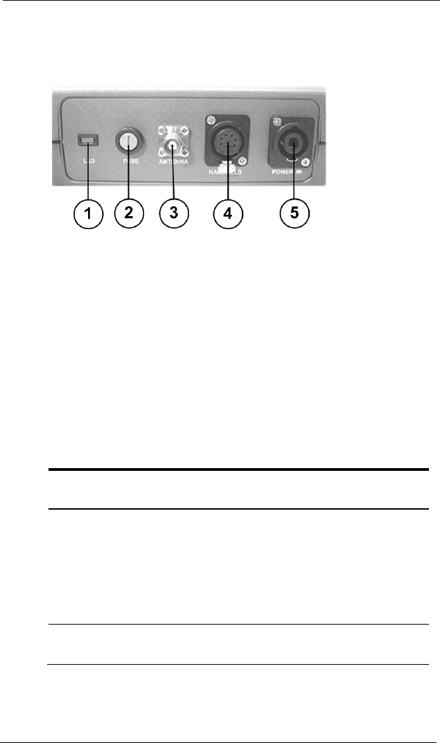
RF Unit Features
The following illustration identifies the connectors and other features
on the back of the MC Lite RF unit.
1. Radio status LED
2. Fuse
3. Coaxial antenna connector
4. Handheld communication/power port
5. Power supply socket
The LED Status Indicator
The MC Lite RF unit has a light-emitting diode (LED) radio status
indicator that shows when the unit is in stand-by mode and when its
radio is turned on.
LED indication
Explanation
Blinking Stand-by mode. The RF unit has power, but the
radio is not turned on.
Steady The radio is turned on:
• The RF unit retrieves meter data from all
endpoints within its range.
• If the route contains at least one wake-up
endpoint, the RF unit's wake-up transmitter
is also functioning.
Off The RF unit is not receiving power. Check
power connections and fuse.

Installing the MC Lite Hardware Components
4 Mobile Collector Lite
Proprietary and Confidential
Installing the MC Lite Hardware Components
Before you can use the MC Lite to collect meter data in the field, you
must:
• Install the MC Lite hardware.
• Set up the handheld data collector. See the handheld’s getting
started guide for details.
• Install the desired meter data collection software on the
handheld. See “Setting Up the Handheld” in the Field Collection
System Handheld User Guide or “Installing the MVR Handheld
Software” in the MV-RS Installation Guide.
The following section explains how to install the hardware
components included in the MC Lite installation package in a
vehicle. It includes procedures to:
√
Task
Description
1
Mount the handheld vehicle dock in the vehicle,
using the +- Ram Mount double-socket connector.
Note A variety of bases (not included in the Mobile
Collector Lite installation package) are available for
use with the connector to address specific
characteristics of different vehicle makes and
models. For details, contact Gamber-Johnson at
www.gamberjohnson.com or Ram Mounting
Systems at www.ram-mount.com. Itron shall have
no liability or obligation due to installation or
programming of the equipment or licensed software
that was not performed by Itron.
2
Mount the MC Lite RF unit on the passenger-side
seat back. See To mount the MC Lite RF unit
(radio) on the seat back on page 5.

Installing the MC Lite Hardware Components
Mobile Collector Lite 5
Proprietary and Confidential
√
Task
Description
3
Connect the RF unit to the vehicle power supply.
You can do this in either of two ways.
• For a permanent installation, connect the unit to
the vehicle's fuse block. See To install the fuse
block power supply cable on page 8.
• Alternatively, if you purchased the optional 12-
volt DC power supply adapter (formerly called
the "cigarette lighter adapter"), you can use it to
connect the RF unit to the vehicle's 12-volt DC
power supply.
4
Connect the handheld to the RF unit, using the
interface cable provided. See To connect the
handheld to the RF unit on page 10.
This cable provides power to the handheld as well as
communications with the RF unit.
5
Install the antenna mount and connect the antenna
cable to the RF unit. Attach the antenna to the
antenna mount. See Installing the Antenna Mount
and Antenna on page 12.
6
Insert the handheld data collector into the vehicle
dock.
Warning When installing the MC Lite hardware
components, take care to arrange all cables and
wires so they will not be accidentally snagged,
disconnected, or damaged by users during day-to-
day operations.
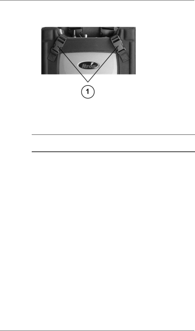
To mount the MC Lite radio on the seat back
1. The RF unit is normally shipped in its vehicle mount. If it has
been removed:
• Slide the RF unit into the vehicle mount.
Installing the MC Lite Hardware Components
6 Mobile Collector Lite
Proprietary and Confidential
• Secure the RF unit in the mount by buckling the two diagonal
corner straps (1).
2. Strap the mount to either the front or the back of the passenger-
side seat back. Position the unit within the mount so that when it
is strapped to the seat back, the unit's connectors face toward the
passenger-side door.
Warning Positioning the unit properly is critical for ensuring
the RF unit's cooling vents will not be blocked.
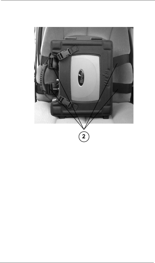
Depending on whether the vehicle has a separate passenger-side
bucket seat or a bench seat, do one of the following:
Installing the MC Lite Hardware Components
Mobile Collector Lite 7
Proprietary and Confidential
• Bucket seat. Extending the mounting straps (2) from the
side of the vehicle mount, wrap them around the seat back
and buckle them to the opposite side of the vehicle mount.
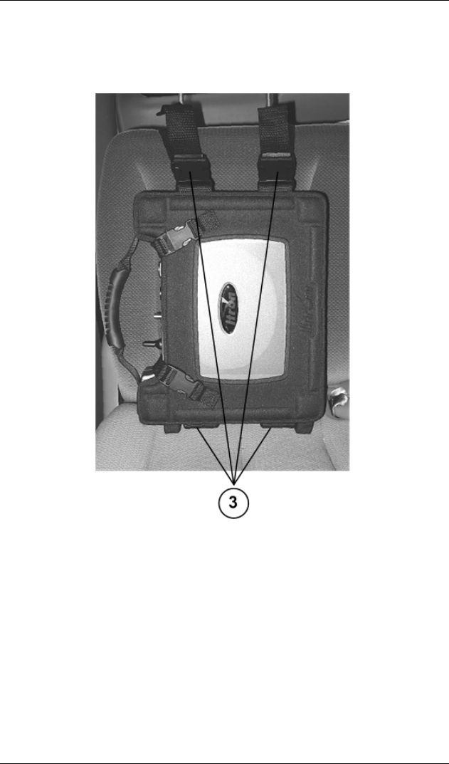
• Bench seat. Connect the optional bench-seat straps (3) to the
buckles on the bottom of the vehicle mount.
Installing the MC Lite Hardware Components
8 Mobile Collector Lite
Proprietary and Confidential
Push the free ends of the straps between the seat cushion and
the seat back, and then extend them up and over the top of
the seat back and connect them to the buckles on the top of
the vehicle mount.
3. Tighten the straps until the RF unit is snug against the seat back.
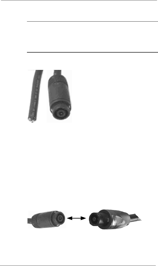
To install the fuse block power supply cable
The unterminated end of the power extension cable connects to the
vehicle’s electrical system and remains in the vehicle so that you can
easily disconnect and connect the other end to the RF unit.
1. Select a location in the vehicle for the connector end of the cable
so that it reaches the cable that connects to the RF unit. An
extension cable is available from Itron if needed.
Installing the MC Lite Hardware Components
Mobile Collector Lite 9
Proprietary and Confidential
2. Route the unterminated end of the cable to the voltage and
grounding sites in the vehicle.
Warning Do not route the cable where it can become abraded
or damaged, such as under a carpet in high-traffic areas, over
sharp edges, near hot engine components, near brake or clutch
linkages, or where it might be exposed to oil or other corrosive
liquids.
3. Trim the cable to a suitable length, if necessary.
4. Connect the cable’s white wire (pin 1) to a spare 15-ampere fuse
in the vehicle’s fuse panel that is not turned on and off by the
vehicle’s ignition (unswitched).
5. Connect the black wire (pin 2) directly to the vehicle’s chassis
ground.
6. Connect the green wire (pin 3) to a spare fuse in the vehicle’s
fuse panel that has a rating of at least 1 ampere and receives
power that is turned on with the vehicle’s ignition set to
accessories (switched).
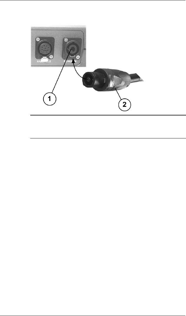
7. Plug the RF unit's power supply extension cable into the unit's
power connector.
Installing the MC Lite Hardware Components
10 Mobile Collector Lite
Proprietary and Confidential
8. Plug the RF unit's power supply extension cable (2) into the
unit’s power connector (1).
Note If you purchased the portable kit, use the 12-volt DC
power supply adapter to connect the RF unit to the 12-volt DC
power supply outlet.
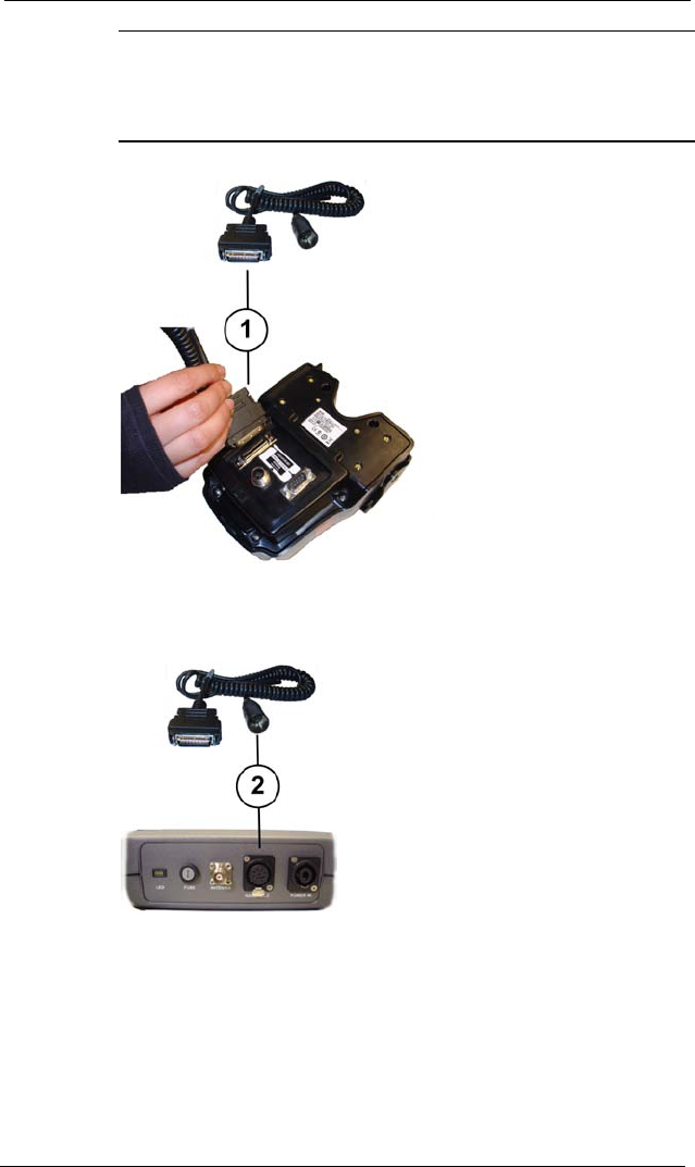
To connect the handheld to the RF unit
1. Using the MC Lite - handheld vehicle dock cable, make the
following connection to the vehicle dock.
Plug the cable’s I/O (input/output) connector (1) into the vehicle
dock’s I/O (input/output) port.
Installing the MC Lite Hardware Components
Mobile Collector Lite 11
Proprietary and Confidential
Note This example shows the FC300 vehicle dock and
appropriate cable. If you have an FC200, use the FC200 vehicle
dock cable to plug into the Power port on the back of the FC200
vehicle dock.
2. Plug the interface connector of the cable (2) into the handheld
connector (labeled HANDHELD) on the back of the MC Lite RF
unit.

Installing the MC Lite Hardware Components
12 Mobile Collector Lite
Proprietary and Confidential
Installing the Antenna Mount and Antenna
To reduce potential radio interference to other users, the antenna type
and its gain should be so chosen that the equivalent isotropically
radiated power (e.i.r.p.) is not more than that permitted for successful
communication.
The following procedures summarize the RF antenna manufacturer's
instructions, which ship with the antenna components. Itron
recommends consulting the manufacturer's instructions in addition to
this installation guide.
When deciding where to mount the antenna:
• Choose a flat area on the vehicle's roof, where the metal of the
roof is .02-.04 inches thick.
• Install the antenna at least 12 inches from any other antennas or
metal structures on the vehicle’s roof that could disrupt
communication with endpoints.
• To meet RF exposure safety requirements, the antenna must be
installed 21.7 inches (55 cm.) from where any bystanders might
be.
To install the antenna mount
These procedures refer to the permanent antenna mount. If you
purchased the Portability Kit, place the magnetic antenna base on the
roof in an appropriate spot and follow steps 7 through 10, to attach it
to the RF unit.
1. If the vehicle has a headliner, remove it and the adjacent trim
pieces and/or dome light if necessary to gain access to the
antenna mounting location from inside the vehicle.
Caution This Device has been designed to operate with the antennas listed
below, and having a maximum gain of 5 dBi. Antennas not included in this
list or having a gain greater than 5 dBi are strictly prohibited for use with this
device. The required antenna impedance is 50 ohms.
Use only Itron-approved and supplied antennas.
Installing the MC Lite Hardware Components
Mobile Collector Lite 13
Proprietary and Confidential
Note Do not shorten or secure any cabling until you are sure
how you want to route it to the RF unit and whether it will reach.
2. Cut a ¾-inch diameter hole in the roof at the selected location.
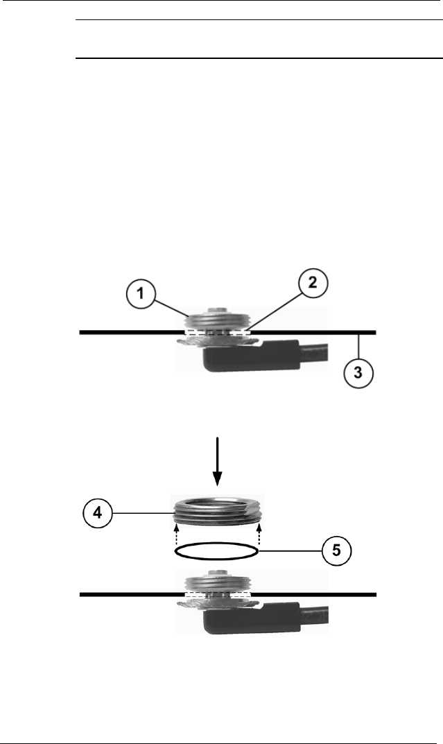
3. Unscrew and remove the lock nut and O-ring from the bushing
assembly.
4. Feed the antenna cable through the hole from the top of the
vehicle, until the bushing assembly is in position to drop into the
hole.
5. Tilt the bushing (1) at a slight angle, and feed it into the hole (2)
in the roof (3).
(The threaded top of the bushing is too large to fall through the
hole.)
6. Making sure the O-ring (5) is in the groove on the bottom of the
lock nut (4), screw the lock nut onto the bushing.
Tighten the lock nut until it secures the assembly in place on the
roof and the O-ring is fully compressed.
7. Route the cable along the inside of the vehicle to the point where
the RF unit is mounted.
Installing the MC Lite Hardware Components
14 Mobile Collector Lite
Proprietary and Confidential
If desired, tape it in place or otherwise attach it to the inside
surfaces.
8. Make sure it reaches the RF unit with sufficient slack to connect
to the coaxial antenna connector.
9. Replace the headliner, trim, and/or dome light you removed
earlier.
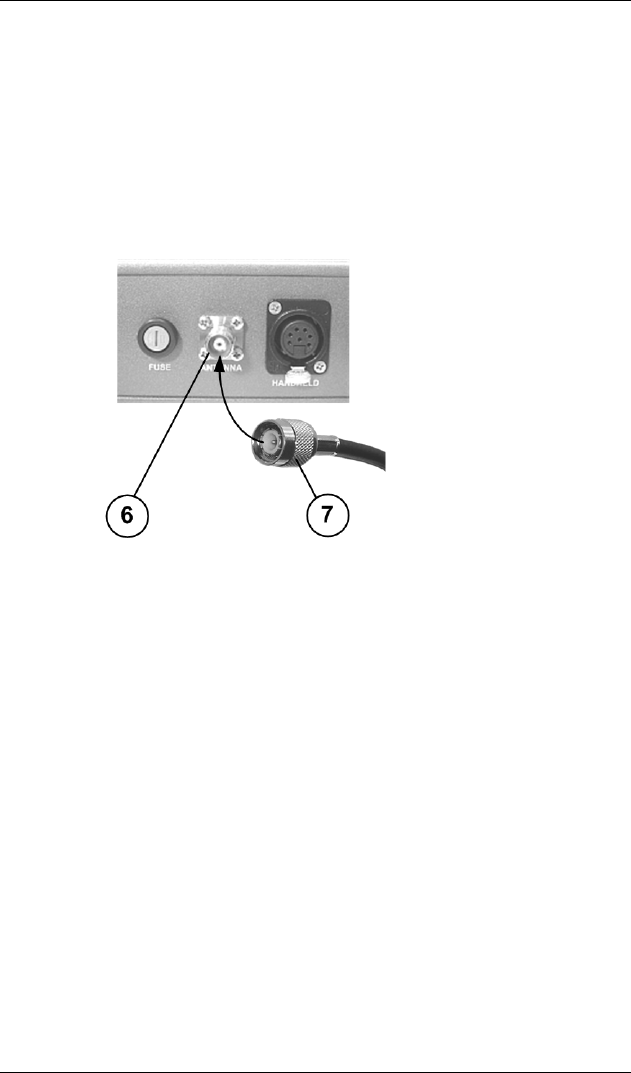
10. Connect the antenna cable (7) to the RF unit’s coaxial antenna
connector (6).
To attach the antenna
1. Clean the bottom of the antenna and the mounting surface
around the lock nut.
2. Apply a bead of silicone sealant to the roof surface around the
lock nut.
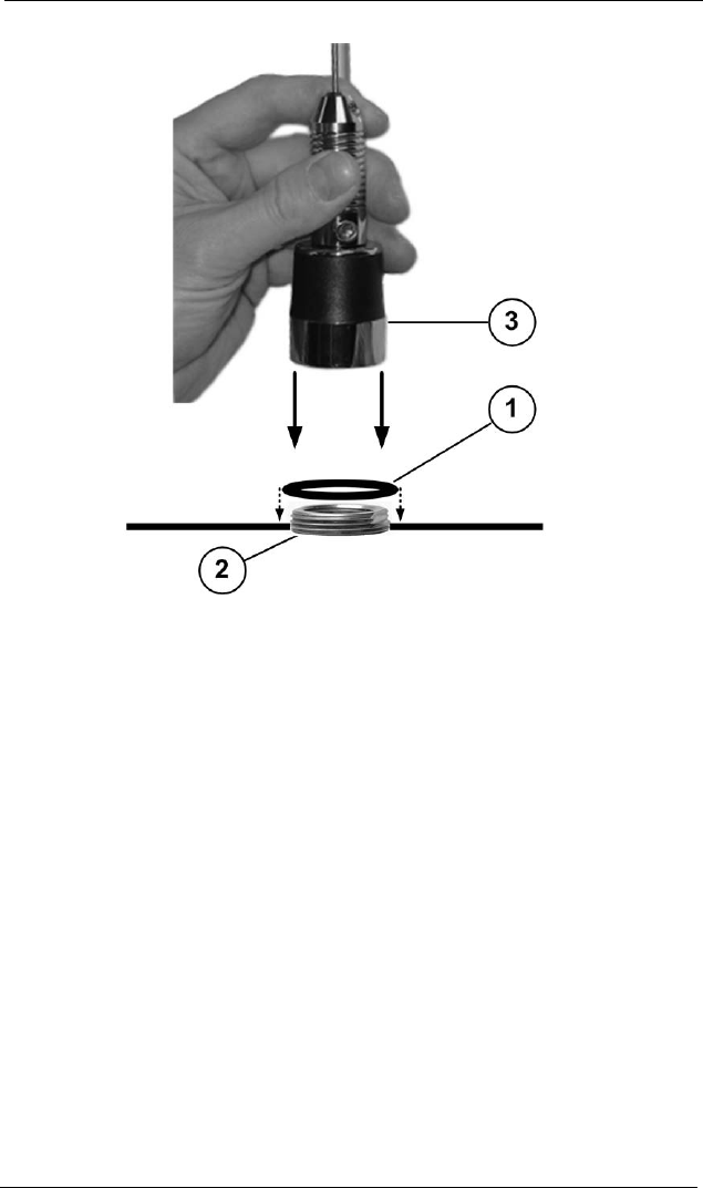
3. Place the gasket (1) provided with the antenna-mount kit over
the lock nut (2).
4. The antenna base comes with a washer inside. Making sure the
washer remains in place, screw the antenna base (3) onto the
lock nut. This should squeeze the gasket between the antenna
base and the roof, creating a moisture seal.
Installing the MC Lite Hardware Components
Mobile Collector Lite 15
Proprietary and Confidential
5. Tighten the antenna base until the antenna is firmly attached.