Itron DCU5310U AMR Transceiver Device User Manual Mobile Collection Hardware Installation Guide
Itron, Inc. AMR Transceiver Device Mobile Collection Hardware Installation Guide
Itron >
Contents
- 1. Users Manual 1
- 2. Users Manual 2
Users Manual 2

ChoiceConnect
Mobile Collection Hardware Installation Guide

Identification
Mobile Collection Hardware Installation Guide
11 November 2010 TDC-0770-004
Copyright
© 2007 - 2010 Itron, Inc. All rights reserved.
Confidentiality Notice
The information contained herein is proprietary and confidential and is being provided subject to the condition that (i) it be held in confidence except to the extent required otherwise by
law and (ii) it will be used only for the purposes described herein. Any third party that is given access to this information shall be similarly bound in writing.
Trademark Notice
Itron is a registered trademark of Itron, Inc.
All other product names and logos in this documentation are used for identification purposes only and may be trademarks or registered trademarks of their respective companies.
Suggestions
If you have comments or suggestions on how we may improve this documentation, send them to TechnicalCommunicationsManager@itron.com
If you have questions or comments about the software or hardware product, contact Itron Technical Support:
Compliance
This device complies with Part 15 of the FCC Rules. These limits are designed to provide reasonable protection against harmful interference in a residential installation. Operation is
subject to the following two conditions:
• This device may not cause harmful interference.
• This device must accept any interference that may cause undesirable operation.
This device must be permanently mounted such that it retains a distance of 55 centimeters (21.7 inches) from all persons in order to comply with FCC RF exposure levels.
USA, FCC Class B - Part 15
This equipment has been tested and found to comply with the limits for a Class B digital device, pursuant to Part 15 of the FCC Rules. These limits are designed to provide reasonable
protection against harmful interference in a residential installation. This equipment generates, uses, and can radiate radio frequency energy and, if not installed and used in accordance
with the instructions, may cause harmful interference to radio communications. However, there is no guarantee that interference will not occur in a particular installation.
If this equipment does cause harmful interference to radio or television reception, which can be determined by turning the equipment off and on, the user is encouraged to try to correct
the interference by one or more of the following measures:
• Reorient or relocate the receiving antenna.
• Increase the separation between the equipment and receiver.
• Connect the equipment into an outlet on a circuit different from that to which the receiver is connected.
• Consult the dealer or an experienced radio or TV technician for help.
This equipment has been tested and found to comply with the limits, pursuant to Part 15 of the FCC Rules. These limits are designed to provide reasonable protection against harmful
interference in a residential installation. Operation is subject to the following conditions:
• This device may not cause interference.
• This device must accept any interference that may cause undesired operation of the device.
CANADA, DOC ICES-003
This digital apparatus does not exceed the class B limits for radio noise emissions from digital apparatus set out in the Radio Interference Regulations of the Canadian Department of
Communications, standard ICES-003.
This equipment complies with policies RSS-210 and RSS-GEN of the Industry Canada rules.
Operation is subject to the following two conditions: (1) this device may not cause interference, and (2) this device must accept any interference, including interference that may cause
undesired operation of the device.
Note Modifications to the device or its antenna not expressly approved by the party responsible for compliance could void the user’s authority to operate the device.
Avis de conformite aux normes du Ministere des Communications du Canada.
Le present appareil numerique n emet pas de bruits radioelectriques depassant les limites applicable aux appareils numeriques classe B prescrites dans le Reglement sur le brouillage
radioelectrique edicte par le Ministere des Communications du Canada, NMB-003.
Disclaimer
RF EXPOSURE
To comply with FCC requirements, maintain a separation distance of at least 55.0 centimetres between the antenna and all persons.
ELECTROMAGNETIC COMPATIBILITY
Use only approved accessories with this equipment. In general all cables must be high quality, shielded, correctly terminated, and normally restricted to 2 meters in length. The Mobile
Collector Lite employs special provisions to avoid radio interference and should not be altered or substituted.
Unapproved modifications or operation beyond or in conflict with these instructions for use, may void authorization by the authorities to operate the equipment.
Warning Do not visually monitor or physically adjust the Mobile Collection
system while driving. While driving, rely on the beeps produced when meter
data is collected to indicate proper system operation. Visually monitoring or
adjusting the Mobile Collection system while driving will divert your attention
from your safe driving responsibilities. Attention to driving is your primary
responsibility, along with following all the applicable driving regulations.
Contact
• Internet: www.itron.com
• E-mail: support@itron.com
• Phone: 1 877 487 6602

Mobile Collection Hardware Installation Guide iii
Proprietary and Confidential
Before You Begin .......................................................................................................... v
How This Document is Organized ....................................................................................................... v
Documentation Conventions ............................................................................................................... v
Chapter 1 Using the MC3 System ............................................................................... 1
About the MC3 System ....................................................................................................................... 1
Mobile Collection Hardware Kit ................................................................................................. 2
Installing the MC3 System ................................................................................................................... 3
Mobile Collector Sled ................................................................................................................ 3
Seat Belt Pretensioner .............................................................................................................. 4
Installing the Junction Box ........................................................................................................ 5
Vehicle Docks ........................................................................................................................... 6
Locking and Unlocking the Toughbook Vehicle Dock .................................................... 7
Locking and Unlocking the GoBook XR-1 Vehicle Dock ................................................ 9
PCMCIA CompactFlash Card Adapter – GoBook .................................................................. 11
Mounting the MC3 ................................................................................................................... 12
Connecting the Toughbook to the MC3 .................................................................................. 14
MC3 Connectors ........................................................................................................... 15
Connecting the Power Cables ...................................................................................... 16
Selecting a Location and Connecting the Antennas ..................................................... 20
Connecting Side-Looker Antennas ............................................................................... 21
Connecting the GPS and Data Cables ......................................................................... 23
Connecting the GoBook XR-1 to the MC3 .............................................................................. 25
Removing the MC3 System ............................................................................................................... 26
Disconnecting the Cables ....................................................................................................... 28
Chapter 2 Using the Mobile Collection 2.x System ................................................. 31
About the Mobile Collection 2.x System ............................................................................................ 31
Mobile Collector 2.x Radio - GoBook III ....................................................................... 31
Mobile Collector 2.x Radio - GoBook MAX................................................................... 32
Flash Card Reader .................................................................................................................. 32
Compact Flash Cards ............................................................................................................. 33
LEDs ....................................................................................................................................... 33
Locking Mechanism - (GoBook) .............................................................................................. 33
Rear Connectors ..................................................................................................................... 34
Mobile Collector Sled .............................................................................................................. 35
GoBook Mounting Systems ............................................................................................................... 35
Direct Mounting Options ......................................................................................................... 36
Vehicle Dock / Pedestal Option .............................................................................................. 36
Installing the Mobile Collection 2.x System ....................................................................................... 36
Attach the Mobile Collector 2.x to the Sled ............................................................................. 36
Connect the Antennas and Power Cables .............................................................................. 38
Attach the GoBook to the Mobile Collector 2.x ....................................................................... 39
Attach the GoBook III to the Vehicle Dock ................................................................... 42
To attach the Toughbook to the vehicle dock ............................................................... 43
Contents

Contents
iv Mobile Collection Hardware Installation Guide
Proprietary and Confidential
Connect the GoBook III Power Supply and USB Cable ......................................................... 43
Flash Card Used in Mobile Collector 2.x Systems .................................................................. 45
Removing the Mobile Collection 2.x System ..................................................................................... 46
Chapter 3 System Maintenance ................................................................................. 51
RF Antenna Maintenance .................................................................................................................. 51
Replacing Gaskets ............................................................................................................................ 51
2.x System Maintenance ................................................................................................................... 52
Inspecting and Replacing Filters ............................................................................................. 52
Service Bulletins ................................................................................................................................ 52
Mobile Collection 2.5 / GoBook III Power Plug Issue ............................................................. 53
Mobile Collector 2.x Power Adapter........................................................................................ 53

Mobile Collection Hardware Installation Guide v
Proprietary and Confidential
Mobile meter readers should use this document to install and operate the Mobile
Collection hardware system. For detailed information on the system, its components, and
system administration and maintenance, see the Mobile Collection Administration Guide.
This guide assumes that vehicle preparation—which includes installing the integrated
antenna, power cables, and, if appropriate, attaching the necessary GPS cables—has been
completed. Detailed information on vehicle preparation is provided in the Mobile
Collection Vehicle Preparation Guide. Detailed information on installing necessary GPS
equipment is provided in the Mobile Collection GPS Installation Guide. Unqualified
personnel should not prepare a vehicle for the Mobile Collection system.
How This Document is Organized
This document is organized as follows:
Chapter 1, Using the MC3 System on page 1 describes how to use and install the
hardware components of the Mobile Collection 3.x system.
Chapter 2, Using the Mobile Collection 2.x Radio on page 31 describes how to use and
install the hardware components to older versions of the Mobile Collector radio.
Chapter 3, System Maintenance on page 51 describes how to keep your Mobile Collection
system in optimal working order.
Documentation Conventions
The following documentation conventions are used:
Convention
Example
Keypresses are in bold. Press Enter when complete.
Menu paths are in bold. From the Start menu, choose File > Save As.
(This example instructs the user to choose File from the Start
menu; then choose Save As from the File menu.)
Computer commands to be typed by the user
are in a
monospace
font. At the C: prompt, type cd itron/bin
File names are in a
monospace
font. The data is uploaded to the
upload.dat
file.
Hypertext links are in blue. See Copyright for identification information.
Caution This type of note warns the user that failure to heed the information in the
note could result in loss of data. Be sure to carefully read a caution note and heed
the advice/instructions.
Before You Begin

Chapter 1 Before You Begin
vi Mobile Collection Hardware Installation Guide
Proprietary and Confidential
Note This type of note indicates neutral or positive information that stresses or
supplements important points of the main text. A note supplies information that
may apply only in special cases.
Warning A warning indicates that failure to take or avoid a specified action
could result in physical harm to the user or the hardware.

Mobile Collection Hardware Installation Guide 1
Proprietary and Confidential
The MC3 is a mobile collection system for electric, gas, and water providers. It offers
advanced radio technology for unsurpassed performance, along with a sophisticated
mapping application utilizing GPS technology that provides a visual indication of
endpoint location. This document provides directions on installing the components of the
MC3 system.
About the MC3 System
Before installing the MC3 system components as outlined in this document, be sure that
the following pre-installation requirements are complete:
• The seat belt pretensioner is installed in the Mobile Collection vehicle using the
Mobile Collection System Sled and Pretensioner Install Guide (TDC-0708-xxx)
• The Mobile Collection vehicle is prepared using the Mobile Collector Vehicle
Preparation Guide (TDC-0382-xxx).
• If using the pedestal option, ensure that you have already ordered and installed the
pedestal base per the manufacturer's installation instructions for your vehicle.
Note A variety of bases (not included in the Mobile Collection installation
package) are available for use with the connector to address specific
characteristics of different vehicle makes and models. For details, contact
Gamber-Johnson at www.gamberjohnson.com or Ram Mounting Systems at
www.ram-mount.com. Itron shall have no liability or obligation due to
installation or programming of the equipment or licensed software that was not
performed by Itron.
If your vehicle is equipped with passenger-side air bag, Itron strongly recommends
disabling it when the Mobile Collection system is installed. The force of the air bag
deploying can damage the laptop, radio, or other components of the system.
Warning Install the Mobile Collection system in the vehicle as described in this
document and those listed above. Failure to do so could lead to injury or death
from unsecured components during a collision.
CHAPTER 1
Using the MC3 System
Chapter 1 Using the MC3 System
2 Mobile Collection Hardware Installation Guide
Proprietary and Confidential
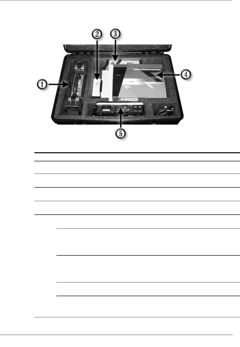
Mobile Collection Hardware Kit
The Mobile Collection hardware kit includes the following components:
Indicator Component Description
1 MC3 radio Includes a mounting harness and straps for installing the system in your vehicle.
2 Sled Installs in the vehicle's passenger seat with the attached seat belt pretensioner.
3 Mobile Collection
laptop dock The Mobile Collection laptop, power cables, and communication cables attach to
the dock.
4 Mobile Collection
software Hard copy of the Mobile Collection software for imaging or recovery of the
Mobile Collection laptop.
5 Mobile Collection
laptop Runs the Mobile Collection software to collect reads.
Not
Pictured
Cables Connect the MC3 and the Mobile Collection laptop dock to the junction box.
USB cable Comes attached to the dock and attaches to the Mobile Collection laptop.
Provides communication between the Mobile Collection laptop and the MC3
radio.
Important Do not disconnect the USB cable from the laptop dock.
Power junction
box Attaches to the sled or to a pedestal mount. Provides power to the Mobile
Collection laptop, MC3 radio, and optional equipment.
The junction box must be installed prior to first use. See Installing the Junction
Box on page 5 for more information.
Omni-mount
antenna Attaches to the top of the vehicle and receives endpoint transmissions.
Type N to TNC
adapter Connects older antennas to the MC3 radio.
Only needed if you are using an MC3 radio with an older omni-mount antenna
(such as one from a v2.5 system) that is already installed on your vehicle.

Installing the MC3 System
Mobile Collection Hardware Installation Guide 3
Proprietary and Confidential
Installing the MC3 System
Installing the Mobile Collection system involves the following tasks:
1. Install the junction box on the vehicle dock.
2. Ensure that the sled and seat belt pretensioner are installed correctly.
3. Mount the MC3 radio on the seat back.
4. Attach and lock the Mobile Collection laptop to the vehicle dock.
5. Connect the Mobile Collection laptop to the MC3 radio.
6. Connect power to the the Mobile Collection junction box.
7. Connect data cables to the Mobile Collection system.
Mobile Collector Sled
The Mobile Collector sled is used to securely fasten the Mobile Collection laptop in the
vehicle. It is placed on the passenger seat and secured with a seat belt and pretensioner.
Watch the Mobile Collector safety video and read the Mobile Collector Sled and
Pretensioner Installation Guide (TDC-0708-xxx) to learn how to correctly install
the sled in your vehicle. These materials are located in a plastic sleeve on the
underside of the sled.
The Mobile Collection laptop dock that is attached to the sled serves as a locking base and
provides power and communications to the laptop.
A power junction box ships in the Mobile Collection kit that needs to be attached to the
sled. When attached, the junction box on the sled should face the passenger side door of
the vehicle (the junction box is attached in the following example).
Install the sled on the passenger seat before mounting the MC3 radio. The sled must be
installed with the seat belt pretensioner; see About the Seat Belt Pretensioner on page 4
for more information.
Chapter 1 Using the MC3 System
4 Mobile Collection Hardware Installation Guide
Proprietary and Confidential
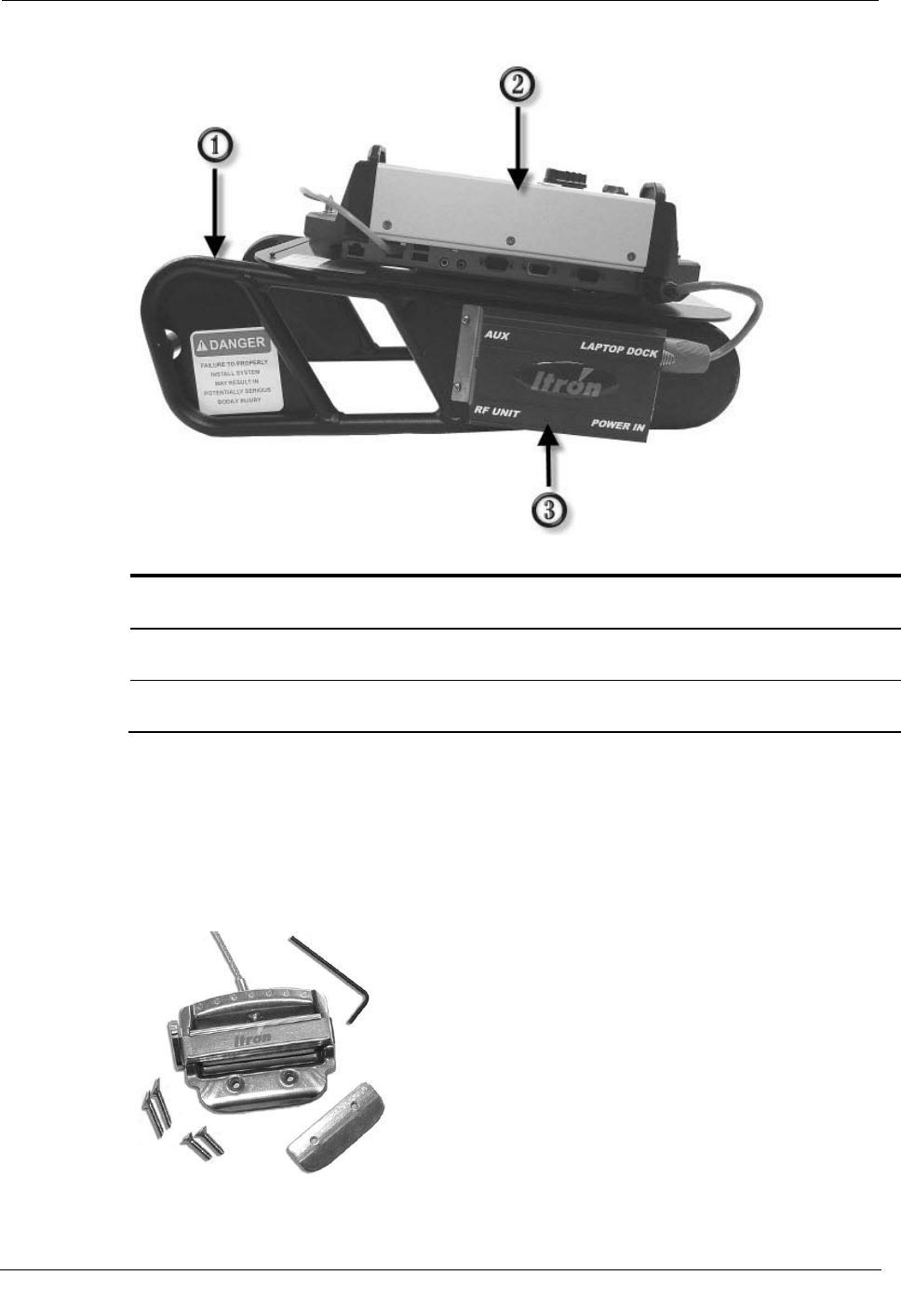
The sled components are shown on the sled below.
ID
Item
Description
1 Mobile Collection sled Attaches to the vehicle passenger seat with the seat belt and pretensioner
system.
2 Mobile Collection laptop dock Attaches to the Mobile Collection laptop and provides a secure base for
the laptop while in the vehicle.
3 Junction box Provides power to the various Mobile Collection components. The
junction box must be attached prior to first use.
Seat Belt Pretensioner
The seat belt pretensioner makes the three-point safety harness in your vehicle function
similarly to a lap seat belt. By using the pretensioner mechanism to cinch the mounting
hardware very firmly into the junction of the seat back and the seat pad, the pretensioner
restricts potentially hazardous equipment movement in the event of an impact.
Installing the MC3 System
Mobile Collection Hardware Installation Guide 5
Proprietary and Confidential
Compared to two-point harnesses, three-point harnesses are designed to provide
additional safety to occupants to lessen injury. By preventing the pay-out of seat belt
webbing designed to protect people and instead using the pretensioner to immobilize
equipment, a higher degree of protection is provided in the event of a collision.
Through standardized safety testing of the Mobile Collection system, Itron has
determined that preventing extensive rotation of the Mobile Collection equipment in a
driver's side impact reduces the stress on mechanical systems to acceptable levels.
Decreasing the amount of equipment rotation towards the driver prevents the fasteners
holding the Mobile Collection laptop and its dock to the sled from separating in a crash.
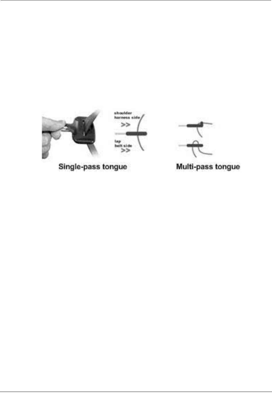
The seat belt pretensioner can be used in vehicles equipped with single-pass and multiple-
pass seat-belt tongues.
To install the seat belt pretensioner
• Follow the procedures in the Mobile Collector Sled and Pretensioner Installation
Guide (TDC-0708-xxx). A DVD showing the installation is also included with your
kit. These materials are located in a plastic sleeve on the underside of the sled.
Installing the Junction Box
The junction box distributes power from the vehicle to the MC3 radio and Mobile
Collection laptop.
The junction box must be installed on the sled or pedestal mount before you can install
the MC3 system for the first time. The junction box must always remain attached to the
sled or pedestal.
To install the junction box
1. Remove the junction box from the MC3 kit.
2. Locate the sled or pedestal mount on which you are installing the junction box. In the
following example, a sled is used.
Chapter 1 Using the MC3 System
6 Mobile Collection Hardware Installation Guide
Proprietary and Confidential
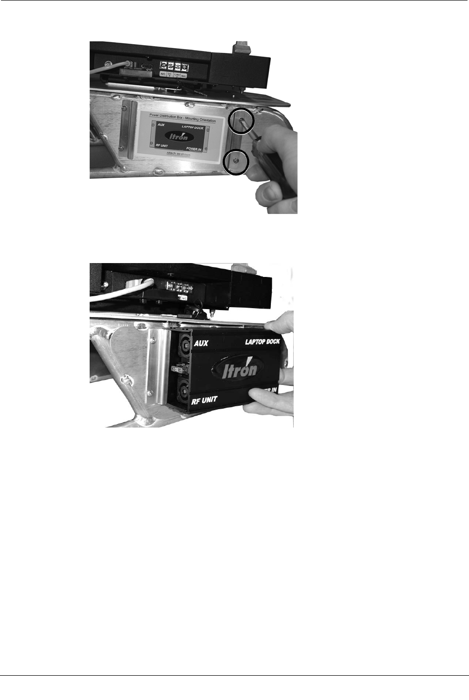
3. Use a Phillips screwdriver to remove the two screws holding the junction box bracket
in place.
4. Slide one end of the junction box into position over the bracket that is still attached.
Be sure to orient the junction box according to the label on the sled or pedestal. The
bracket fits into the recessed edge on the junction box.
5. Insert the other bracket (the one you removed) into the junction box, making sure that
both screw holes are visible through the bracket.
6. Insert and tighten both screws to secure the junction box to the sled or pedestal.
Vehicle Docks
The Mobile Collection dock is used to secure the Mobile Collection laptop to either the
sled or a pedestal mount in your vehicle. It provides power and communication
connections between the Mobile Collection laptop and Mobile Collector radio.
Docks are also available for use with the GoBook XR-1 and GoBook III laptops; see
Locking and Unlocking the XR-1 Vehicle Dock on page 9 and Attaching the GoBook III
to the Vehicle Dock for more information.
Installing the MC3 System
Mobile Collection Hardware Installation Guide 7
Proprietary and Confidential
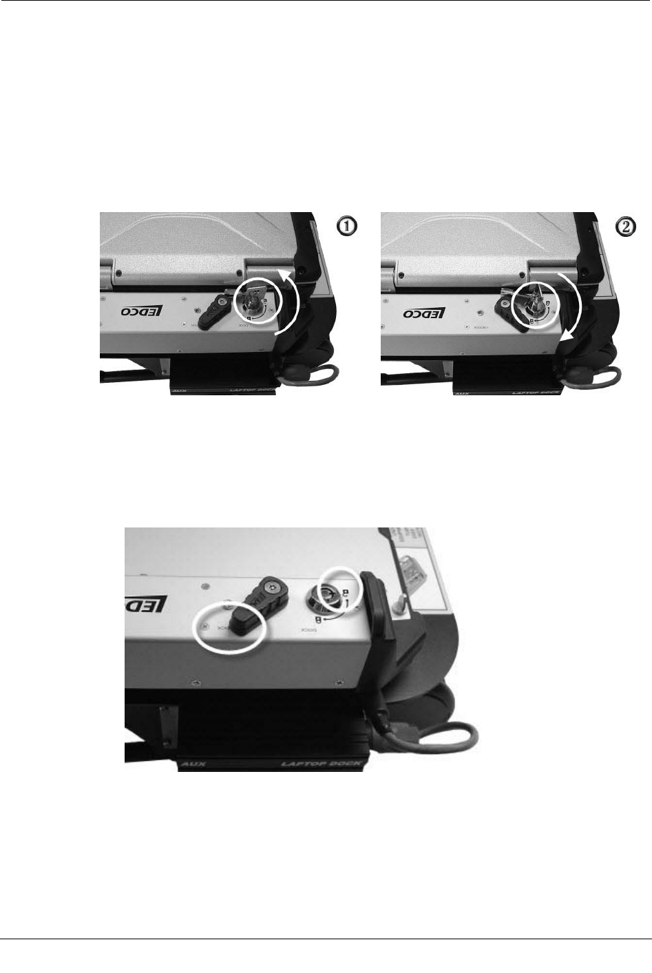
Locking and Unlocking the Toughbook Vehicle Dock
When the Toughbook is attached, the dock must be locked to properly secure the laptop.
To lock the dock for the Toughbook, insert the dock key in the dock lock and turn it
clockwise until the lock is in the locked position. To unlock the dock for the Toughbook,
insert the dock key in the dock lock and turn it counterclockwise until the lock is in the
unlocked position.
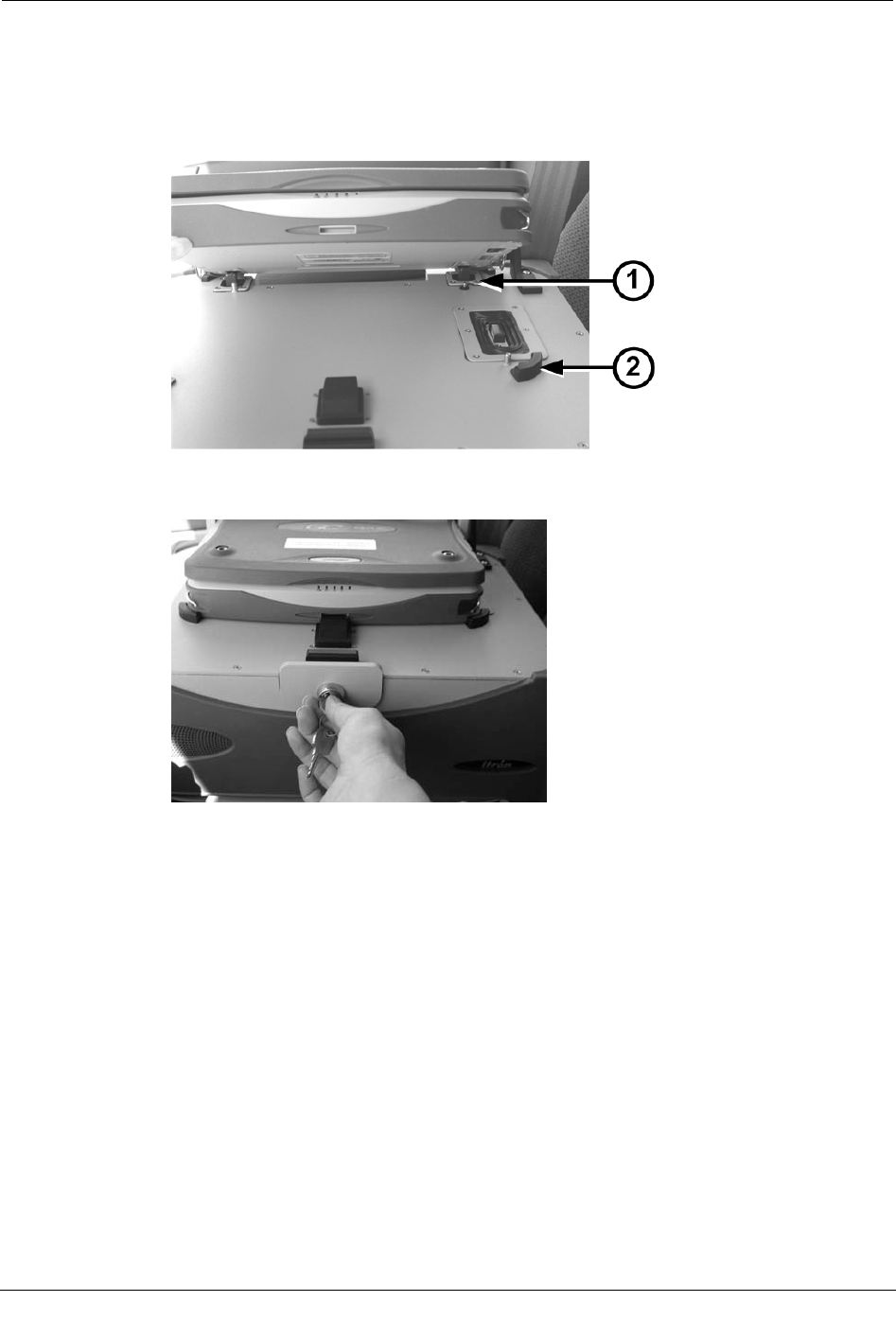
The examples below show the dock on a sled in the unlocked (1) and locked (2) positions,
with a Toughbook attached.
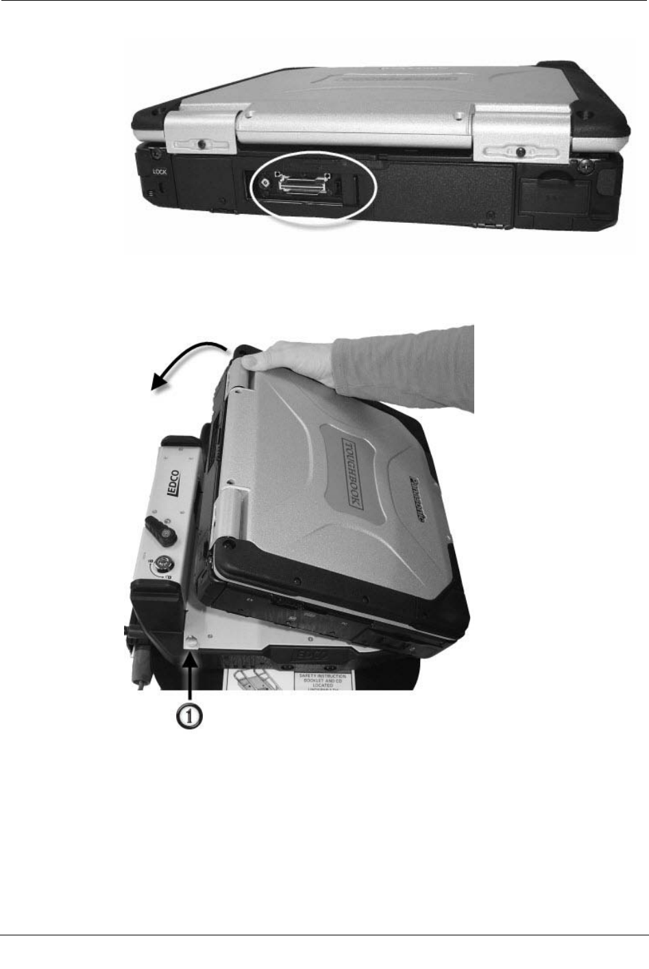
To attach the Toughbook to the vehicle dock
1. Make sure the dock is unlocked and that the docking mechanism is in the Undock
position.
Chapter 1 Using the MC3 System
8 Mobile Collection Hardware Installation Guide
Proprietary and Confidential
2. Make sure the laptop's rear hatch is open.
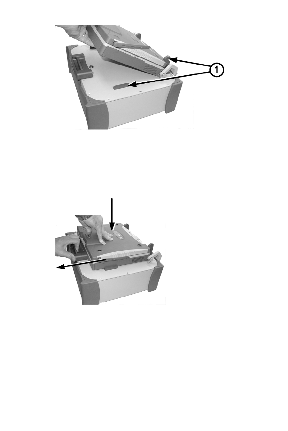
3. Angle the front of the Toughbook down toward the front of the dock. Notice the guide
post (1) near the back of the sled base. This helps ensure proper placement of the
Toughbook.
4. Push the back of the laptop down onto the connectors.
Installing the MC3 System
Mobile Collection Hardware Installation Guide 9
Proprietary and Confidential
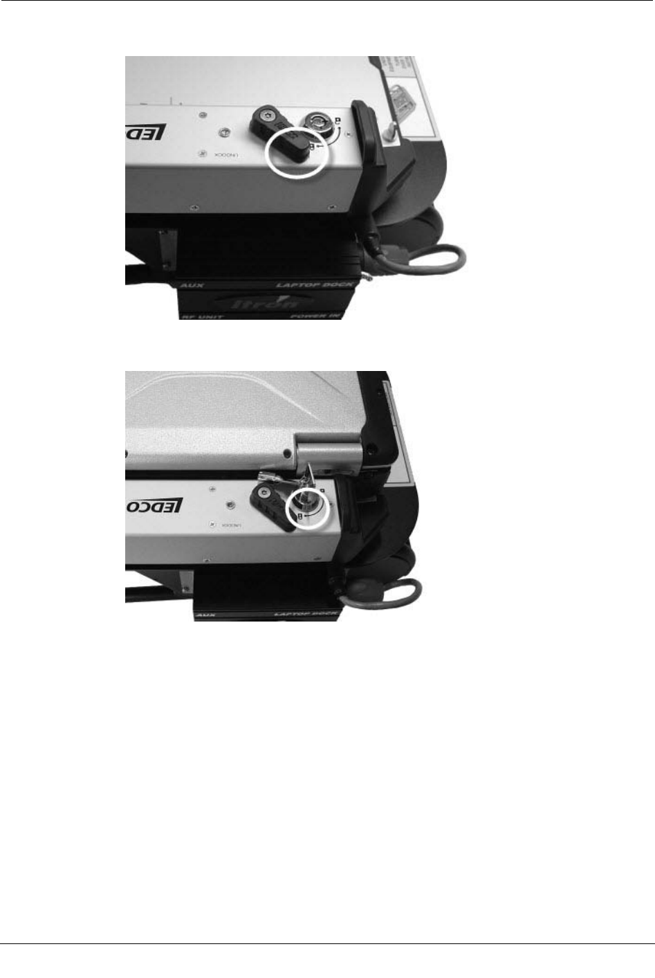
5. When the laptop is in place, switch the docking mechanism to the Dock position to
secure the laptop and prevent it from moving.
6. To lock the dock, insert the dock key in the dock lock and turn it clockwise until the
lock is in the locked position.
Locking and Unlocking the GoBook XR-1 Vehicle Dock
When the GoBook XR-1 is attached, the dock must be locked to properly secure the
laptop. While in the locked state, the dock's locking mechanism extends out further from
the sled than when in the unlocked position. A green button also appears next to the
locking mechanism when the dock is locked.
To lock or unlock the dock for the GoBook XR-1, push the mechanism in, move it toward
the keys on the front of the dock, and then slide it back toward its original position. The
mechanism works in a "V" pattern to lock or unlock the dock.
The examples below show the dock on a sled in the unlocked (1) and locked (2) positions,
with a GoBook XR-1 attached to the dock.
Chapter 1 Using the MC3 System
10 Mobile Collection Hardware Installation Guide
Proprietary and Confidential
A dock is also available for use with the Toughbook and GoBook III laptops. See Locking
and Unlocking the Toughbook Vehicle Dock on page 7 and Attaching the GoBook III to
the Vehicle Dock for more information.
To attach the GoBook XR-1 to the Vehicle Dock
1. Make sure the dock is in the unlocked position.
2. Angle the front of the GoBook down, toward the front of the dock (where the key and
locking mechanism are). Notice the connectors and guide posts (1) near the back of
the sled base. These help ensure proper placement of the GoBook.
3. Push the back of the laptop down onto the connectors.
4. When the laptop is in place, engage the dock locking mechanism to secure the
connectors to the laptop and prevent it from moving.
Installing the MC3 System
Mobile Collection Hardware Installation Guide 11
Proprietary and Confidential
5. Push the keyed mechanism in on the front of the dock to further secure the GoBook to
the dock. This helps to prevent the GoBook from being stolen. (Use the supplied key
to release the lock later.)
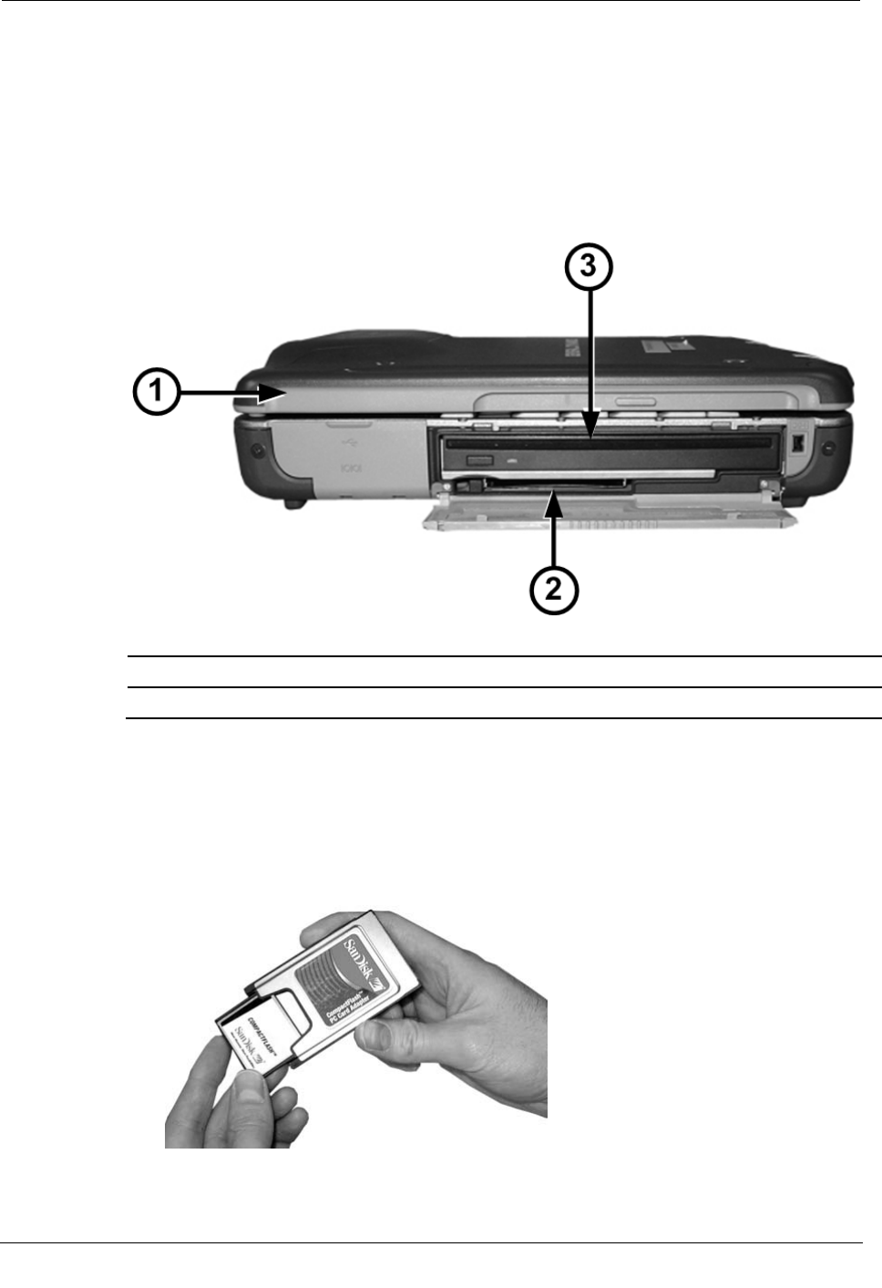
PCMCIA CompactFlash Card Adapter – GoBook
The GoBook includes a PCMCIA slot on the right side, just below the CD drive. Using a
PCMCIA adapter, you can attach and read a CompactFlash card.
1 Front of GoBook XR-1
2 PCMCIA slot
3 CD drive
The GoBook includes a CompactFlash card installed from the factory. If it is not installed
or you wish to replace cards, use the following procedures.
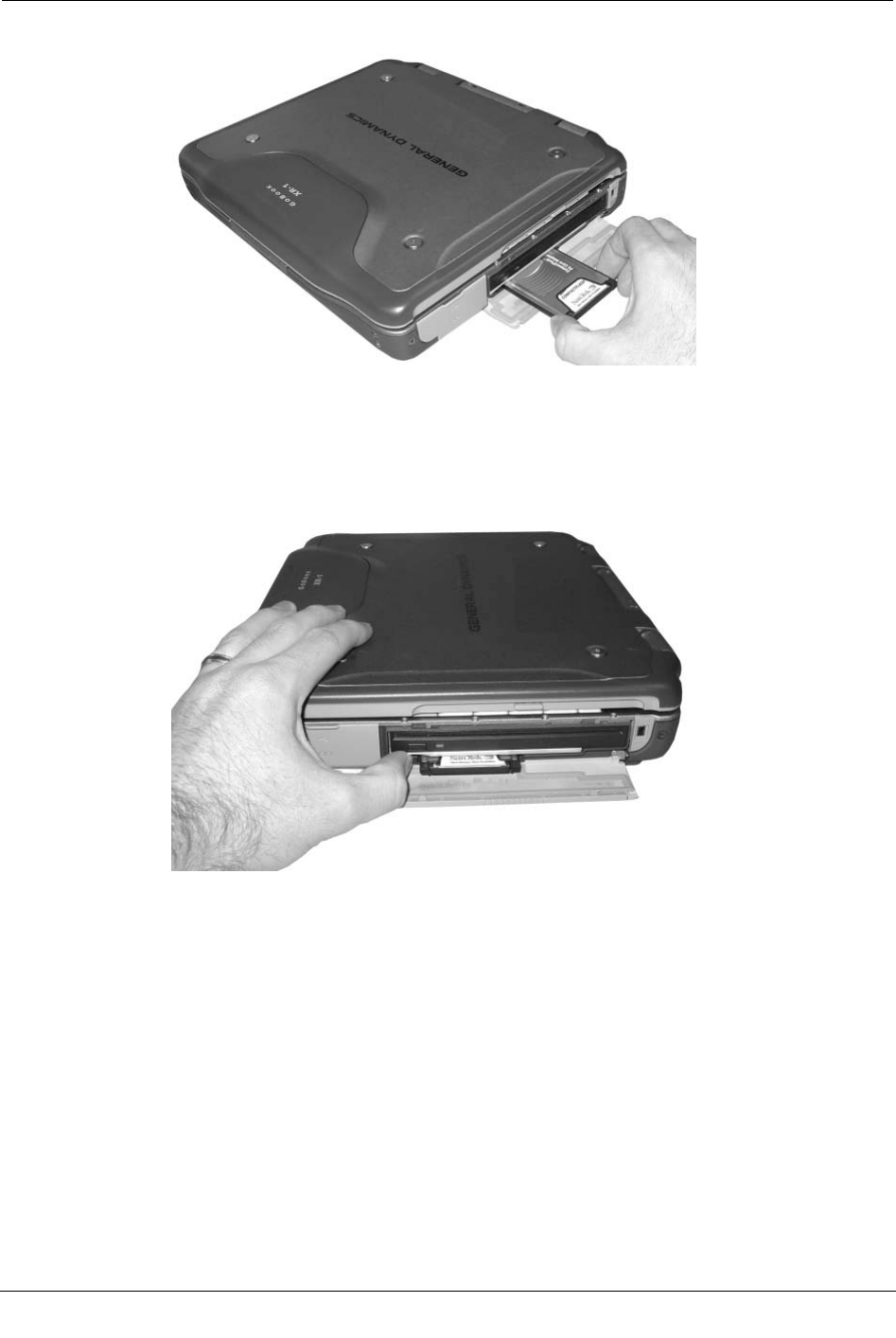
To insert the CompactFlash card adapter – GoBook
1. Slide the CompactFlash card into the PCMCIA adapter.
2. Open the CD drive/PCMCIA slot compartment on the right-hand side of the GoBook.
Chapter 1 Using the MC3 System
12 Mobile Collection Hardware Installation Guide
Proprietary and Confidential
3. Slide the adapter into the PCMCIA slot on the GoBook until it clicks into place.
To remove the CompactFlash card adapter – GoBook
1. Open the CD drive/PCMCIA slot compartment on the right-hand side of the GoBook.
2. Push the button in until the adapter pops out of the slot.
3. Pull the adapter the rest of the way out.
4. Remove the CompactFlash card from the adapter.
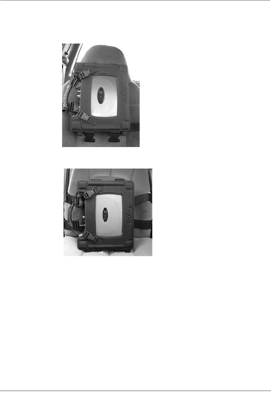
Mounting the MC3
The MC3 is mounted in a harness with clips so that it can attach to either a bucket or
bench seat in a vehicle. The MC3 is shipped in its vehicle mount with the straps set up for
a bucket seat. The bench straps are included with the MC3.
If you are using a sled in either the bucket- or bench-style seat arrangement, you must
attach the MC3 radio high enough on the seat-back to leave room for the sled and Mobile
Collection laptop to fit on the seat beneath the radio.
Installing the MC3 System
Mobile Collection Hardware Installation Guide 13
Proprietary and Confidential
To mount the MC3 on a bucket seat
• Sled Systems. Mount the MC3 high enough on the seat back (as shown in the
following example) so the sled and Mobile Collection laptop fit beneath the radio
on the seat.
• Pedestal Systems. The MC3 radio can be attached to the lower portion of the
seat, as shown below.
1. Position the harnessed MC3 radio so the unit's connectors and handle face towards the
passenger-side door when mounted to either the front or the back of the passenger
seat.
Chapter 1 Using the MC3 System
14 Mobile Collection Hardware Installation Guide
Proprietary and Confidential
2. Extend the mounting straps from the driver-facing side of the vehicle mount (1), wrap
them around the seat back, and buckle them to the opposite side of the vehicle mount
(2).
3. Tighten the straps until the MC3 is secure against the seat-back.
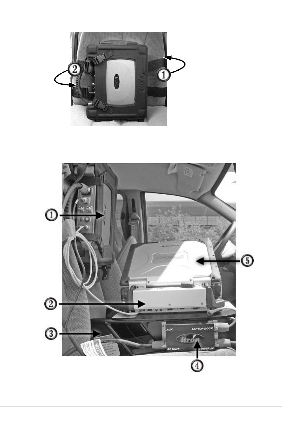
Connecting the Toughbook to the MC3
Installing the MC3 System
Mobile Collection Hardware Installation Guide 15
Proprietary and Confidential
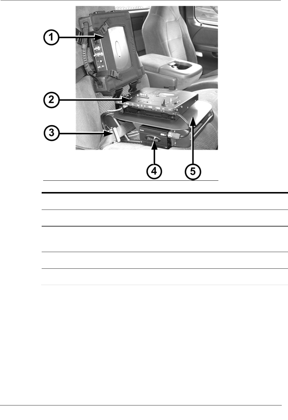
The MC3 rides in a harness that attaches to a bucket- or bench-style passenger seat. The
Mobile Collection laptop sled is equipped with a dock for the laptop and a junction box
for power connectors (the junction box must be attached to the sled prior to use). The sled
should be mounted on the seat before the MC3 radio is attached. The MC3 must be
mounted high enough on the seat so that the right side ports on the Mobile Collection
laptop are accessible, as shown in the example above.
ID Component Description
1 MC3 radio Contains components necessary for collecting mobile reads, such
as the processors, receivers, and GPS equipment.
2 Laptop dock Provides a communication link between the Mobile Collection
laptop and the MC3 radio. Also provides power to the laptop.
3 Sled Attaches to the passenger seat of a vehicle and secures the Mobile
Collection laptop and the dock in place.
4 Junction box Receives power from the vehicle and distributes it to the MC3
radio, the Mobile Collection laptop, and optional equipment.
5 Mobile Collection laptop Runs the Mobile Collection software to collect meter readings.
Not
shown Seat belt pretensioner Secures the sled in the vehicle.
A properly installed sled is vital to ensure your safety while
collecting reads.
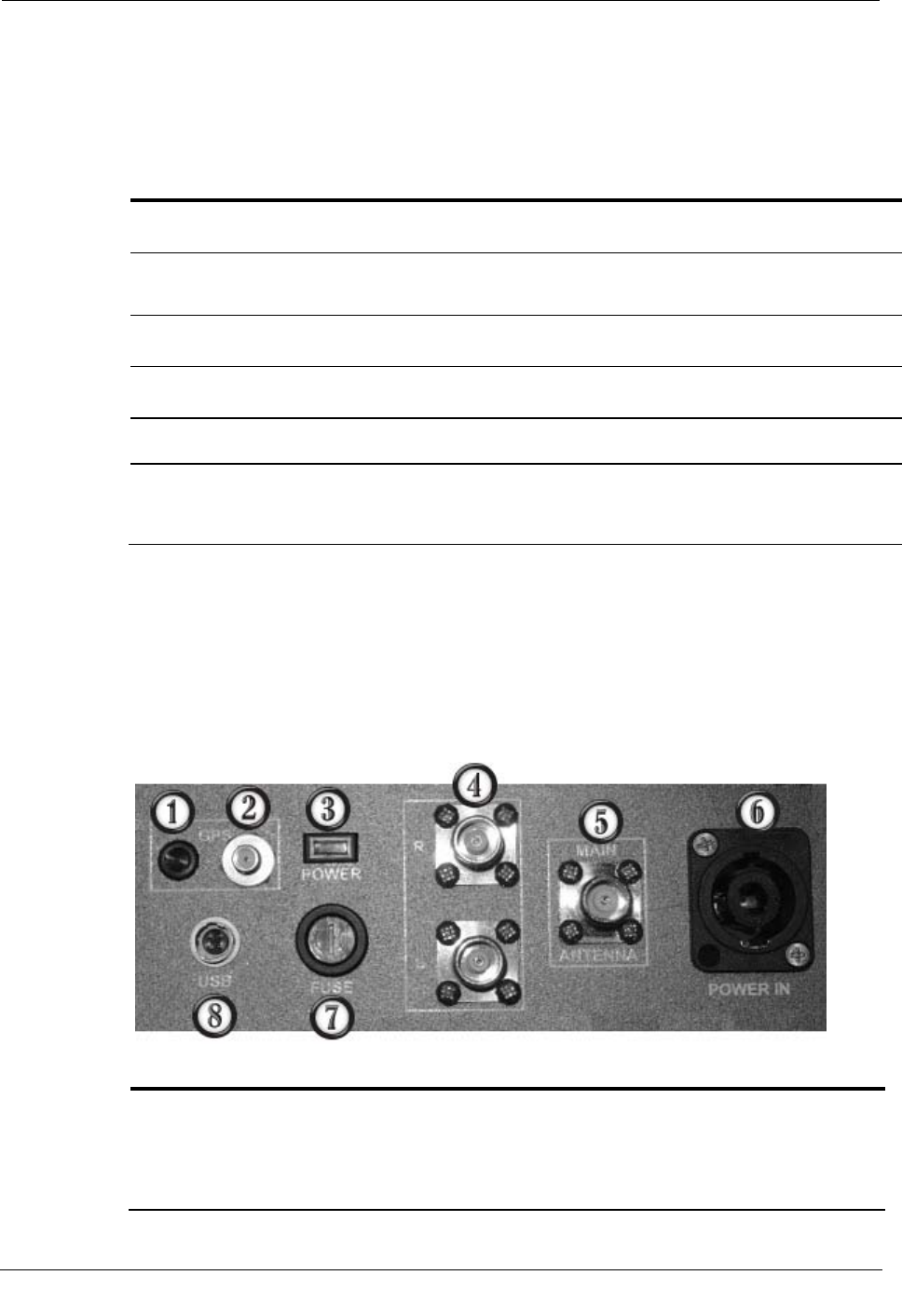
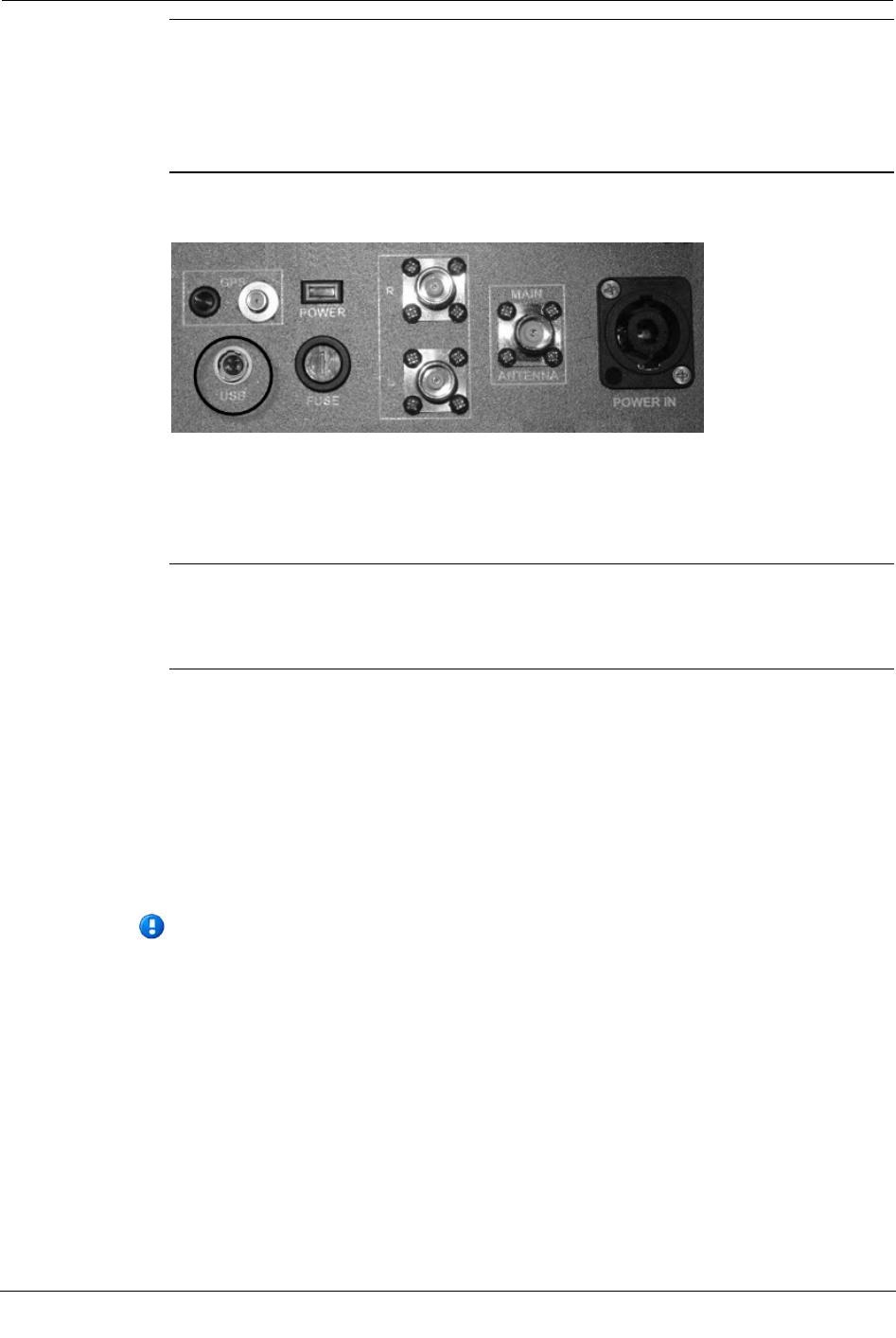
MC3 Connectors
The top of the MC3 radio contains the power and communications connectors, as well as
a fabric and rubber handle used to carry the radio.
The connections on the MC3 are described in the following table.
ID
Connector
Description
1 GPS LED indicator An LED that indicates the status of the GPS antenna.
• A lit LED indicates that the GPS antenna does not have a short in it.
• An unlit LED indicates that the GPS antenna might have a short in it.
See Connecting the GPS and Data Cables for more information.

Chapter 1 Using the MC3 System
16 Mobile Collection Hardware Installation Guide
Proprietary and Confidential
ID
Connector
Description
2 GPS antenna connector Connects the MC3 to the roof-mounted GPS antenna.
3 Power indicator An LED that turns on when the MC3 is receiving power.
• A solid LED indicates that the power is on and connected to the Mobile
Collector laptop
• A flashing LED indicates the power is on, but is not connected to the
Mobile Collection laptop.
4 Side-looker antennas Extra connectors for the optional side-looking, roof-mounted antennas.
Do not use these connectors for the main MC3 antenna.
5 Main antenna Connector for the roof-mounted antenna cable.
6 Vehicle power Input that receives the connector running to the vehicle power source to provide
power to the MC3.
In addition to wiring the power cable directly to the vehicle, a 12-volt DC
power adapter cable is available for emergency use only. Using this cable
disables the power management functions of the MC3 and can adversely affect
system performance. Disconnect this cable from the power source when not in
use. Failure to do so could result in a dead battery.
7 Fuse holder Holder that accepts standard automotive 12V (15amp) ATO fuses (1 included)
to protect internal circuitry from power surges by the vehicle.
8 USB Connects the Mobile Collection laptop to the MC3 radio.
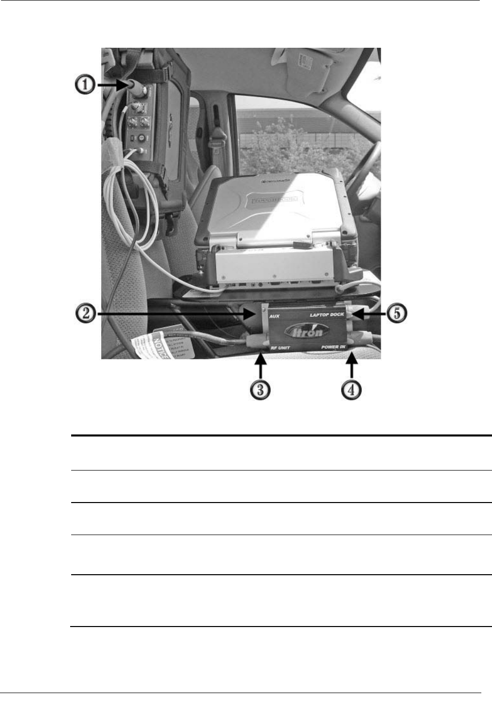
Connecting the Power Cables
Power to the Mobile Collection components is distributed through the junction box on the
side of the sled. There are three power cables that must be connected:
• Vehicle power to the junction box
• Junction box to the Mobile Collection laptop dock
• Junction box to the MC3
Mobile Collection no longer uses the auxiliary (AUX) outlet.
Installing the MC3 System
Mobile Collection Hardware Installation Guide 17
Proprietary and Confidential
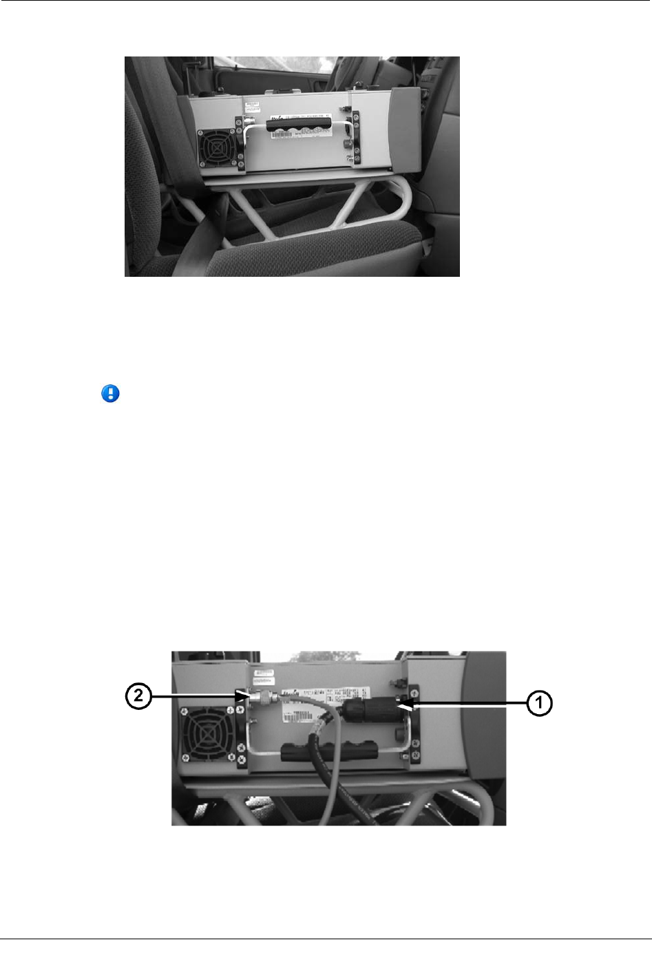
The following example shows an MC3 radio and sled for a Toughbook with all the power
cables connected.
ID Connection
(Label)
Description
1 Power in to MC3 radio
(POWER IN) Power receptacle on MC3 radio.
2 Auxiliary outlet
(AUX)
Mobile Collection no longer uses the auxiliary outlet.
3 Power out to MC3 radio
(RF UNIT)
Connection from junction box to MC3 radio.
4 Power in from vehicle
(POWER IN)
Power source input from the vehicle's battery. This connection is hard-wired to
the vehicle battery. See the Vehicle Preparation Guide (TDC-0382-xxx) for
more information.
5 Power out to laptop dock
(LAPTOP DOCK)
Connection from junction box to the laptop dock. The laptop dock secures the
Mobile Collection laptop in place while you drive a route, and provides power
and communication connections for the laptop. The dock is attached to either a
sled or pedestal mount in the vehicle (a sled is pictured in this example).
Chapter 1 Using the MC3 System
18 Mobile Collection Hardware Installation Guide
Proprietary and Confidential
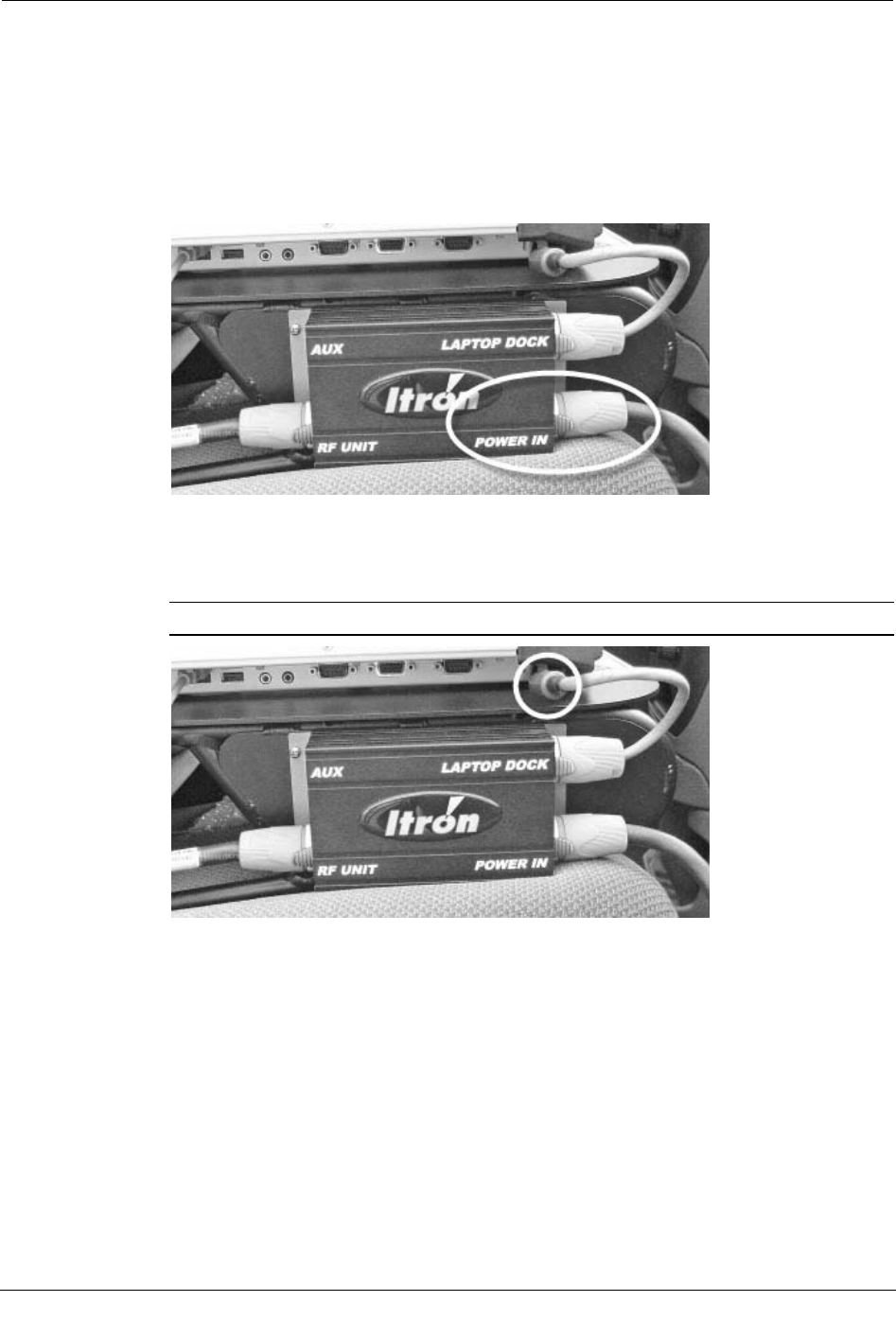
To connect the vehicle power to the sled
• Plug the vehicle power cable into the POWER IN receptacle on the junction box.
Pull the silver tab on the power cable back, insert the connector into the junction box,
twist the connector so the silver tab lines up with the labeling on the junction box, and
release the tab to lock it into place.
The other end of the power cable is hard-wired to the vehicle battery as described in
the Mobile Collection Vehicle Preparation Guide (TDC-0382-xxx).
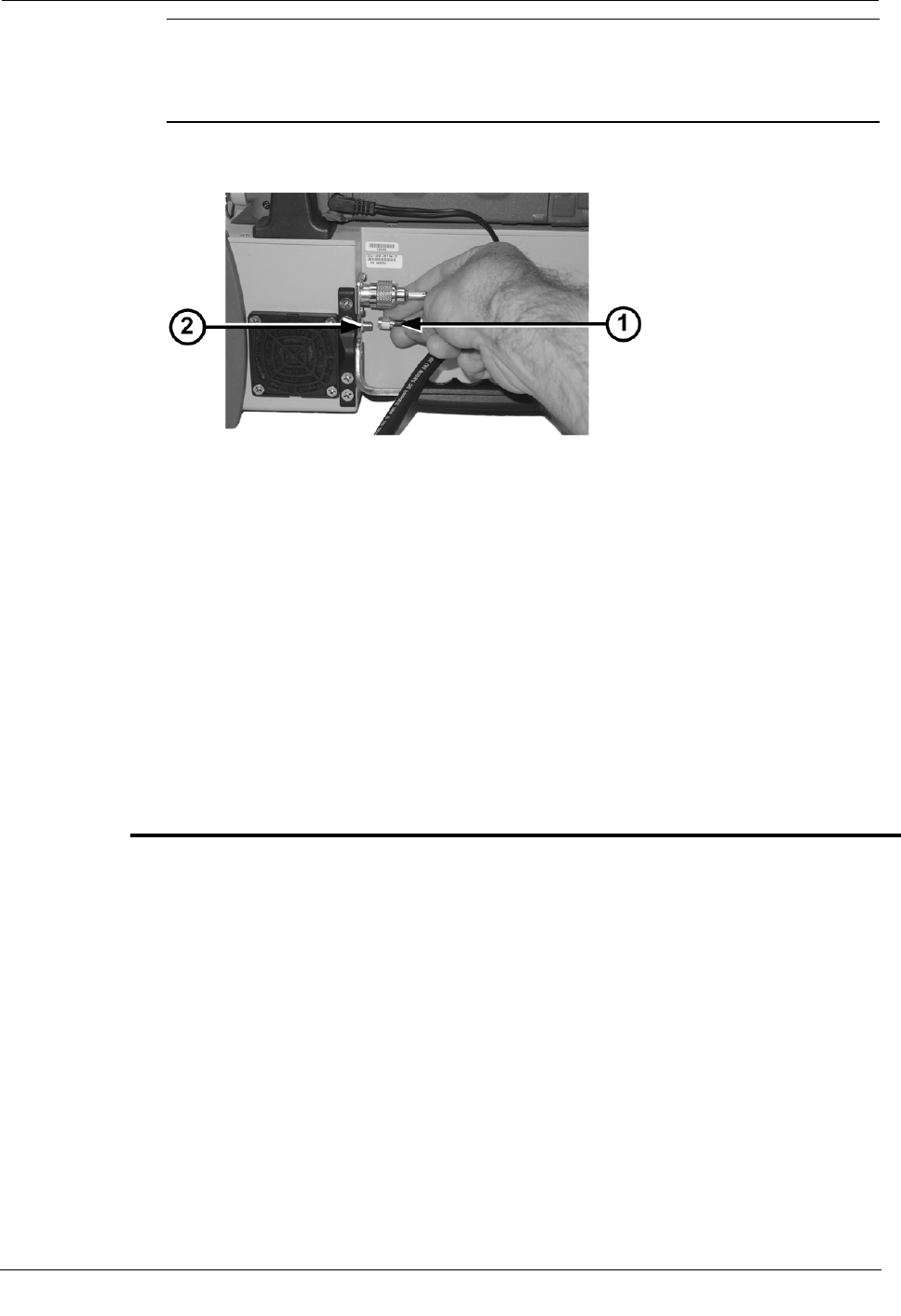
To connect power to the Mobile Collection laptop dock
1. Plug the pigtail end into the dock connector (GoBooks only).
Note The pigtail end is pre-attached to the Toughbook dock.
Installing the MC3 System
Mobile Collection Hardware Installation Guide 19
Proprietary and Confidential
2. Plug the red and blue end of the cable into the LAPTOP DOCK receptacle on
junction box. Pull the silver tab on the power cable back, insert the connector into the
junction box, twist the connector so the silver tab lines up with the labeling on the
junction box, and release the tab to lock it into place.
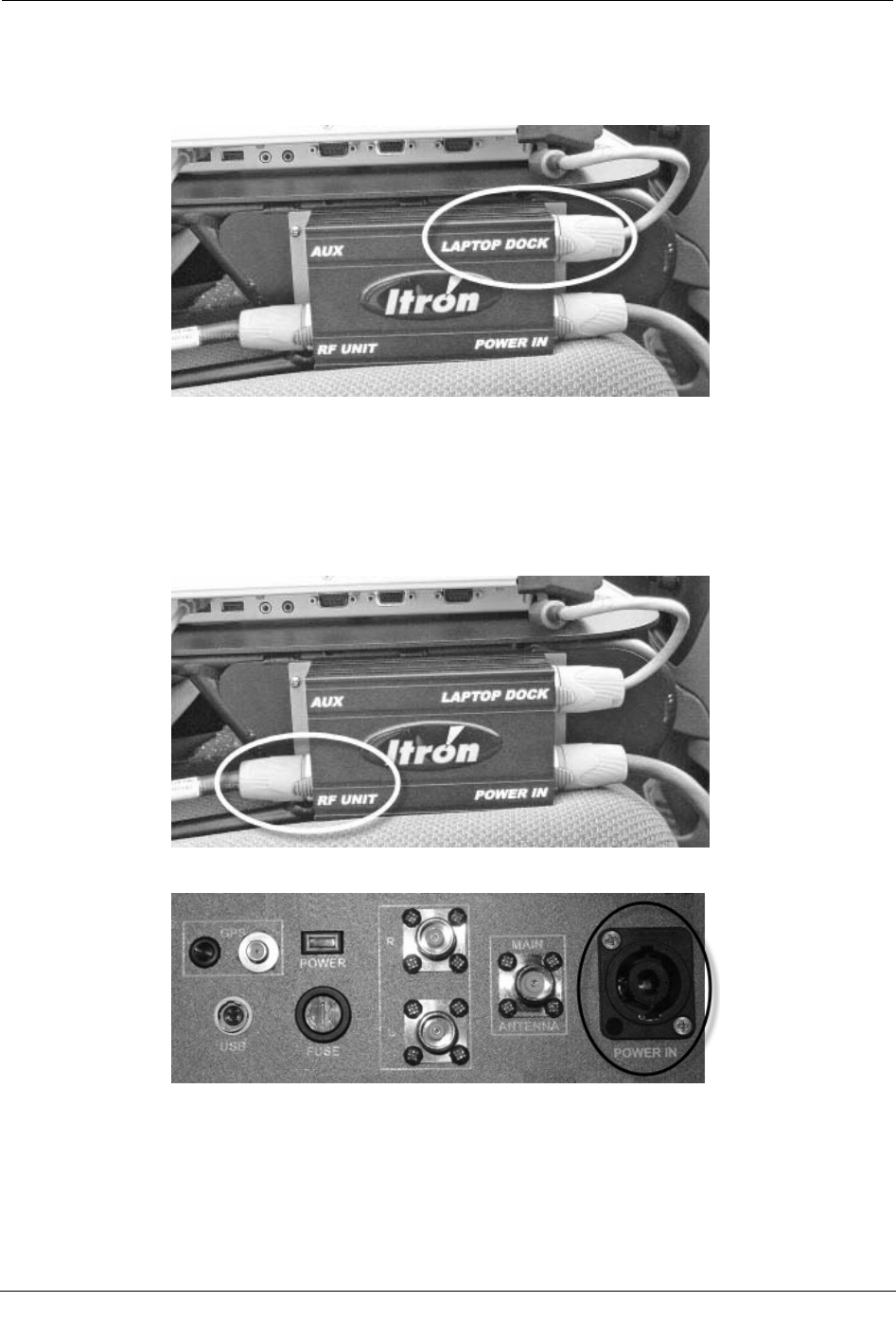
To connect power to the MC3
1. Plug one end of the cable into the RF UNIT receptacle on the junction box. Pull the
silver tab on the power cable back, insert the connector into the junction box, twist the
connector so the silver tab lines up with the labeling on the junction box, and release
the tab to lock it into place.
2. Plug the other end into the POWER IN receptacle on the MC3.
Chapter 1 Using the MC3 System
20 Mobile Collection Hardware Installation Guide
Proprietary and Confidential
Selecting a Location and Connecting the Antennas
To reduce potential radio interference to other users, the antenna type and its gain should
be so chosen that the equivalent isotropically radiated power (e.i.r.p.) is not more than that
permitted for successful communication.
Caution This device has been designed to operate with the antennas listed below,
and having a maximum gain of 5dBi. Antennas not included in this list or having a
gain greater than 5 dBi are strictly prohibited for use with this device. The required
antenna impedance is 50 ohms.
Use only Itron-approved and supplied antennas.
The omni-mount RF antenna has either a fixed-base that is permanently attached to the
vehicle or a magnetic base that can be attached to and removed from the vehicle as
necessary.
When deciding where to mount the antenna:
• Choose a flat area on the vehicle's roof, where the metal of the roof is .02-.04
inches thick.
• Install the antenna at least 12 inches from any other antennas or metal
structures on the vehicle’s roof that could disrupt communication with
endpoints.
• To meet RF exposure safety requirements, the antenna must be installed 21.7
inches (55 cm.) from where any bystanders might be.
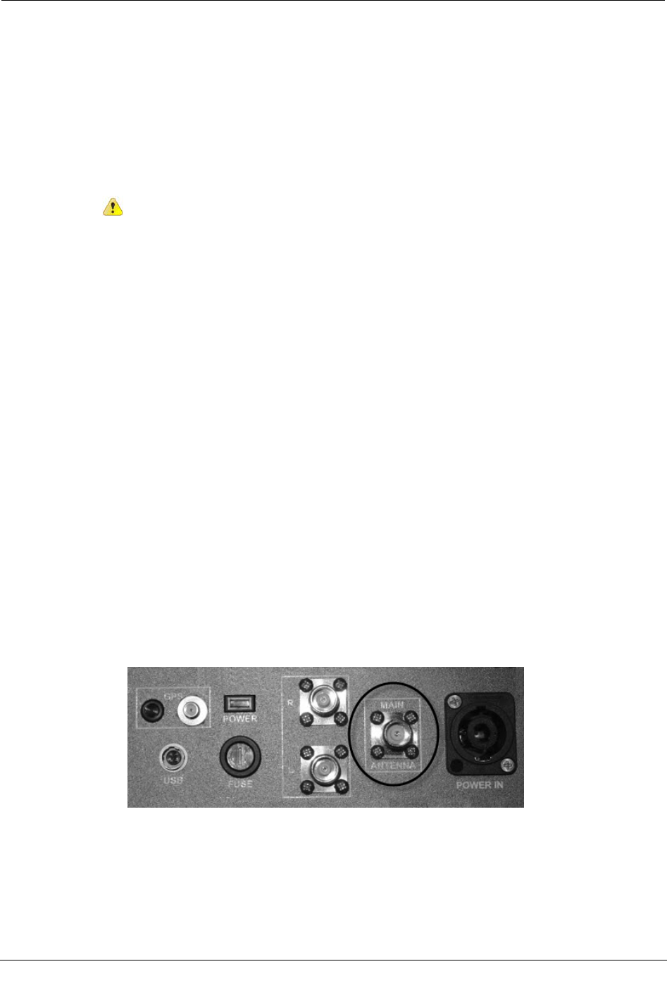
To connect the antenna
• Connect the omni-mount RF antenna cable to the MAIN ANTENNA connector on
the MC3. Be sure to properly tighten the connector. A loose connection can lead to
poor radio and read performance.
Installing the MC3 System
Mobile Collection Hardware Installation Guide 21
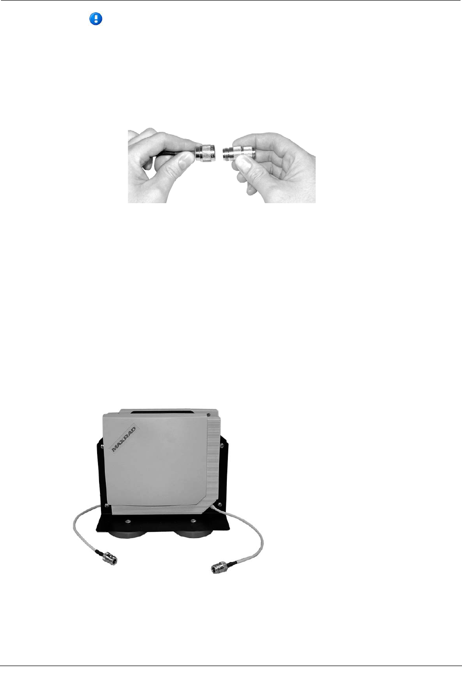
Proprietary and Confidential
When using older antenna cables with type N connectors along with the MC3
radio, a type N to TNC adapter is required; this adapter is included in the MC3 kit.
Attach the adapter securely to both the antenna cable and MC3 to ensure optimal
radio performance. Should you need another adapter or if you are not able to
locate the adapter in the ship kit, contact your Itron representative or Customer
Service (1.800.635.8725) to place an order for an adapter (part number CON-0419-
001).
Connecting Side-Looker Antennas
The MC3 radio supports an additional set of antennas that help to gather additional reads
from endpoints located on each side of the vehicle.
The side-looker antennas are an optional component of the MC3 system that can help
improve read coverage in certain situations. Two additional antennas are connected to one
antenna base, which is then installed on the vehicle. For more information contact your
Itron representative.
Side-looker antennas attach to the top of the vehicle with several strong magnets. If your
vehicle has a fiberglass top, the antennas may not bond securely to the vehicle; Itron does
not recommend the use of side-looker antennas with fiberglass-topped vehicles.
Chapter 1 Using the MC3 System
22 Mobile Collection Hardware Installation Guide
Proprietary and Confidential
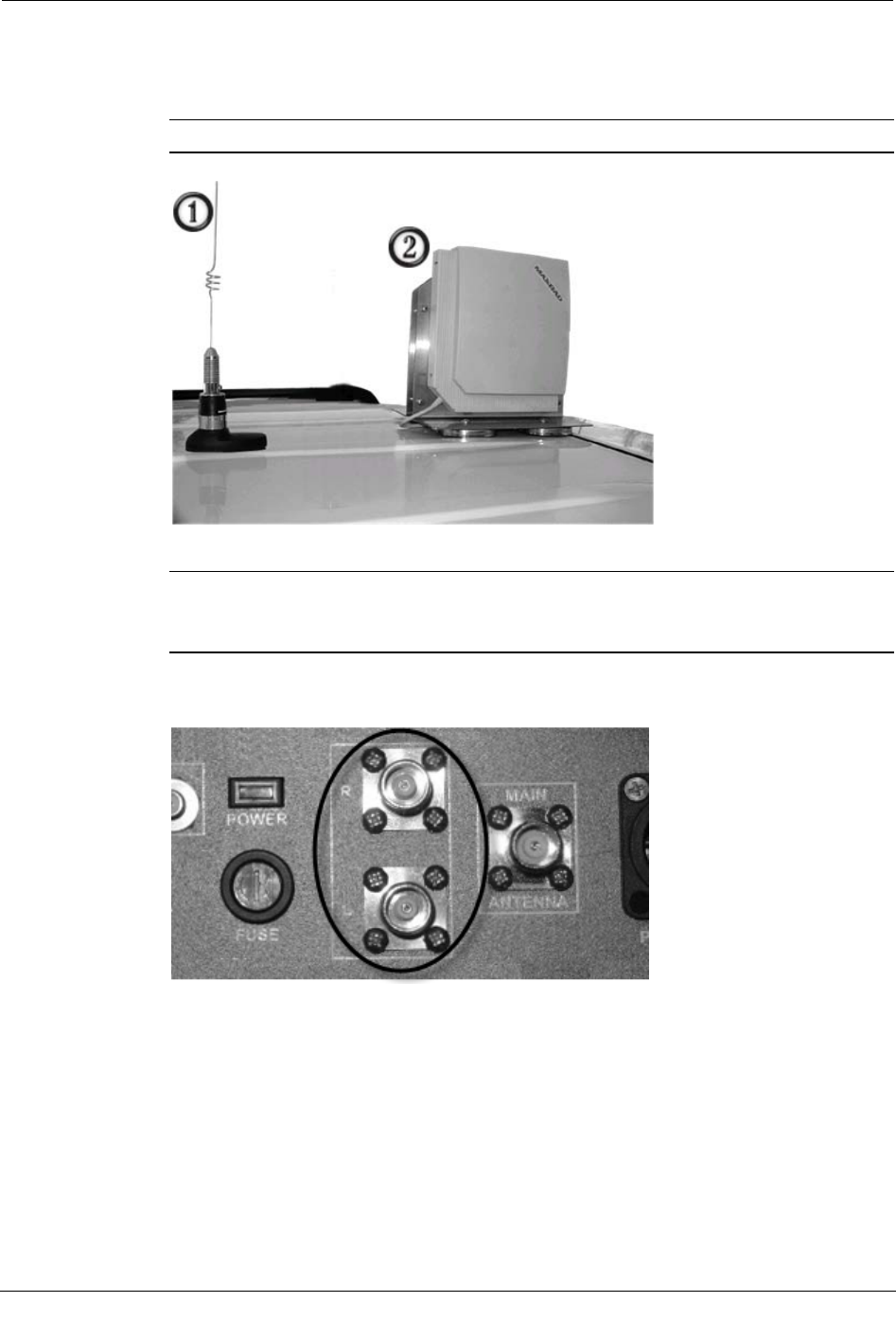
To connect side-looker antennas
1. Mount the side-looker antennas(2) on top of the vehicle, two feet in front of or behind
the primary RF omni-mount antenna(1).
Important Do not separate the individual antennas from the
2. Route the antenna cables into the vehicle, taking care not to pinch or damage them.
Warning When installing take care to arrange all cables so they will not be
accidentally snagged, disconnected, or damaged by users during day-to-day
operations.
3. On the MC3 radio inside the vehicle, remove the caps to expose the side-looker
antenna ports, identified by R and L.

Installing the MC3 System
Mobile Collection Hardware Installation Guide 23
Proprietary and Confidential
4. Connect the side-looker antenna cables to their respective R (right) and L (left)
antenna inputs on the MC3 radio.
Connecting the GPS and Data Cables
GPS and meter data is received and transferred between the MC3 and the Mobile
Collection laptop through a USB cable connecting the laptop dock to the MC3.
Chapter 1 Using the MC3 System
24 Mobile Collection Hardware Installation Guide
Proprietary and Confidential
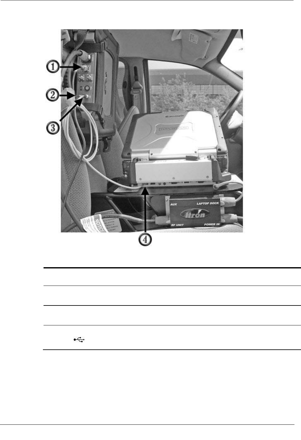
The following picture shows a Mobile Collection system with all the data cables
connected to their respective components.
ID Connection
(Label)
Description
1 RF radio antenna
(MAIN ANTENNA) RF radio antenna connection on MC3 radio. Receives endpoint
signals.
2 GPS antenna
(GPS)
GPS antenna connection to MC3 radio. Receives GPS signal for
vehicle location and tracking.
3 USB data cable
(USB)
USB data output from MC3 radio. GPS and meter data is transferred
from the radio to the laptop through this cable.
4 USB data cable
( )
USB data input on the laptop dock. Data from the MC3 radio is
transferred to the Mobile Collection software running on the Mobile
Collection laptop.
To connect the USB data cable
1. Ensure that the rectangular end of the USB cable is inserted into the Mobile
Collection laptop dock USB port.
Installing the MC3 System
Mobile Collection Hardware Installation Guide 25
Proprietary and Confidential
Caution The USB cable is connected to the dock at the factory and is secured with a
cable tie. DO NOT remove this cable tie or unplug the USB cable from the dock. The
cable tie helps ensure a secure connection and should never be disconnected. The
cable tie also ensures that the correct COM port is used for GPS communications with
the Mobile Interface software. Using a different USB port will prevent the MC3 radio
from communicating properly with the software.
2. Plug the round end of the USB cable into the MC3 radio by pulling the connector
sleeve back, plugging the connector into the receptacle, and releasing the sleeve.
To connect the GPS antenna cable
1. Attach the GPS antenna cable from the roof antenna to the connector on the MC3
radio labeled GPS.
Note When powered on, the LED indicator is lit to indicate there is no short in the
antenna. If the LED indicator is not lit, disconnect and reattach the cable to the GPS
antenna connector. If the LED indicator is lit, continue installing your Mobile
Collection system; if the LED indicator remains unlit, contact Itron support.
Connecting the GoBook XR-1 to the MC3
The MC3 rides in a harness that attaches to bucket- or bench-style passenger seats. The
sled for the GoBook XR-1 is equipped with a dock for the computer and a junction box
for power connectors (the junction box must be attached to the sled prior to use). The sled
should be mounted on the seat before the MC3 radio is attached. The MC3 must be
mounted high enough on the seat so that the right side ports on the GoBook are
accessible, as shown in the example below.
Note For connection instructions see Connecting the Toughbook to the MC3 on
page 14.
Chapter 1 Using the MC3 System
26 Mobile Collection Hardware Installation Guide
Proprietary and Confidential
ID
Component
Description
1 MC 3 radio Houses components necessary for collecting mobile reads, such as the
processors, receivers, and GPS equipment.
2 Laptop dock Provides a communication link between the GoBook and the MC3
radio. Also provides power to the laptop.
3 Seat belt pretensioner Secures the sled in the vehicle.
A properly installed sled is vital to ensure your safety while collecting
reads.
4 Junction box Receives power from the vehicle and distributes it to the MC3 radio,
GoBook, and optional equipment.
5 Sled Attaches to the passenger seat of a vehicle and secures the GoBook and
dock in place.
Removing the MC3 System
At some point, you may need to remove the Mobile Collection system from the vehicle.
Before you do so, stop the Mobile Interface software, shut down the Mobile Collection
laptop, and turn off the vehicle power. For more information see the Mobile Collection
User's Guide (TDC-0380-xxx).
To remove the Mobile Collection laptop from the vehicle dock
1. In the Mobile Interface software stop processing reads.
2. Complete routes.
Removing the MC3 System
Mobile Collection Hardware Installation Guide 27
Proprietary and Confidential
3. Export routes.
4. Shut down all open applications.
5. Shut down the Mobile Collection laptop.
6. Close the Mobile Collection laptop screen.
Caution If you accidentally disconnect the Mobile Collection laptop from the MC3
radio before shutting down Windows and the laptop, the following message appears:
Unsafe Removal of Device
Before clicking OK, clear the ShowUnplug/Eject icon on the Taskbar box. If you do
not clear this box, you will not be able to properly shut down the system in the future.
7. Turn off the vehicle.
8. Disconnect any cables attached directly to the Mobile Collection laptop.
9. If unlocking the Mobile Collection laptop from the vehicle dock:
• Toughbook. Unlock the dock by inserting the dock key into the dock lock and
turning it counter clockwise until the lock is in the Unlock position. Then switch
the docking mechanism to Unlock.

Chapter 1 Using the MC3 System
28 Mobile Collection Hardware Installation Guide
Proprietary and Confidential
• GoBook XR-1. Press the locking mechanism in and slide it toward the keys on
front of the dock (1), and then push it in a little further and pull it back to the
starting position to unlock the dock (2).
• GoBook III. Press the bottom of the locking system underneath the locking
mechanism (1) and then pull the handle out (2) as shown.
10. Gently lift the Mobile Collection laptop up and away from the cradle.
Disconnecting the Cables
Disconnect the cables from the MC3 and leave them in the vehicle for the next installation
of the system.
To disconnect the cables
1. Complete the procedure To remove the Mobile Collection laptop from the vehicle
dock on page 26.
2. Unplug the cables from the MC3 radio.
3. Unplug all the cables from the Mobile Collection laptop dock EXCEPT for:

Removing the MC3 System
Mobile Collection Hardware Installation Guide 29
Proprietary and Confidential
• The USB cable.
• The power cable that is hard-wired to the dock for GoBookIII installations.
4. Unplug the cables from the sled or pedestal junction box.
5. Release the mounting clips on the MC3 harness and remove the MC3 radio.
6. Unbuckle the seat belt securing the sled to the passenger seat and remove the sled
from the vehicle. Leave the pretensioner attached to the seat belt.

Chapter 1 Using the MC3 System
30 Mobile Collection Hardware Installation Guide
Proprietary and Confidential
Mobile Collection Hardware Installation Guide 31
Proprietary and Confidential
This chapter describes how to install and use legacy versions of the Mobile Collector
radio.
If your vehicle is equipped with passenger-side air bag, Itron strongly recommends
disabling it when the Mobile Collection system is installed. The force of the air bag
deploying can damage the laptop, radio, or other components of the system.
About the Mobile Collection 2.x System
The Mobile Collector 2.x radio stores the transmitter, receivers, and other electronics
required to communicate with endpoints.
There are two versions of the Mobile Collector radio; one for use with the GoBook MAX
and one for use with the GoBook III. Both versions contain the same features and
functionality, but may look slightly different, depending on your GoBook version.
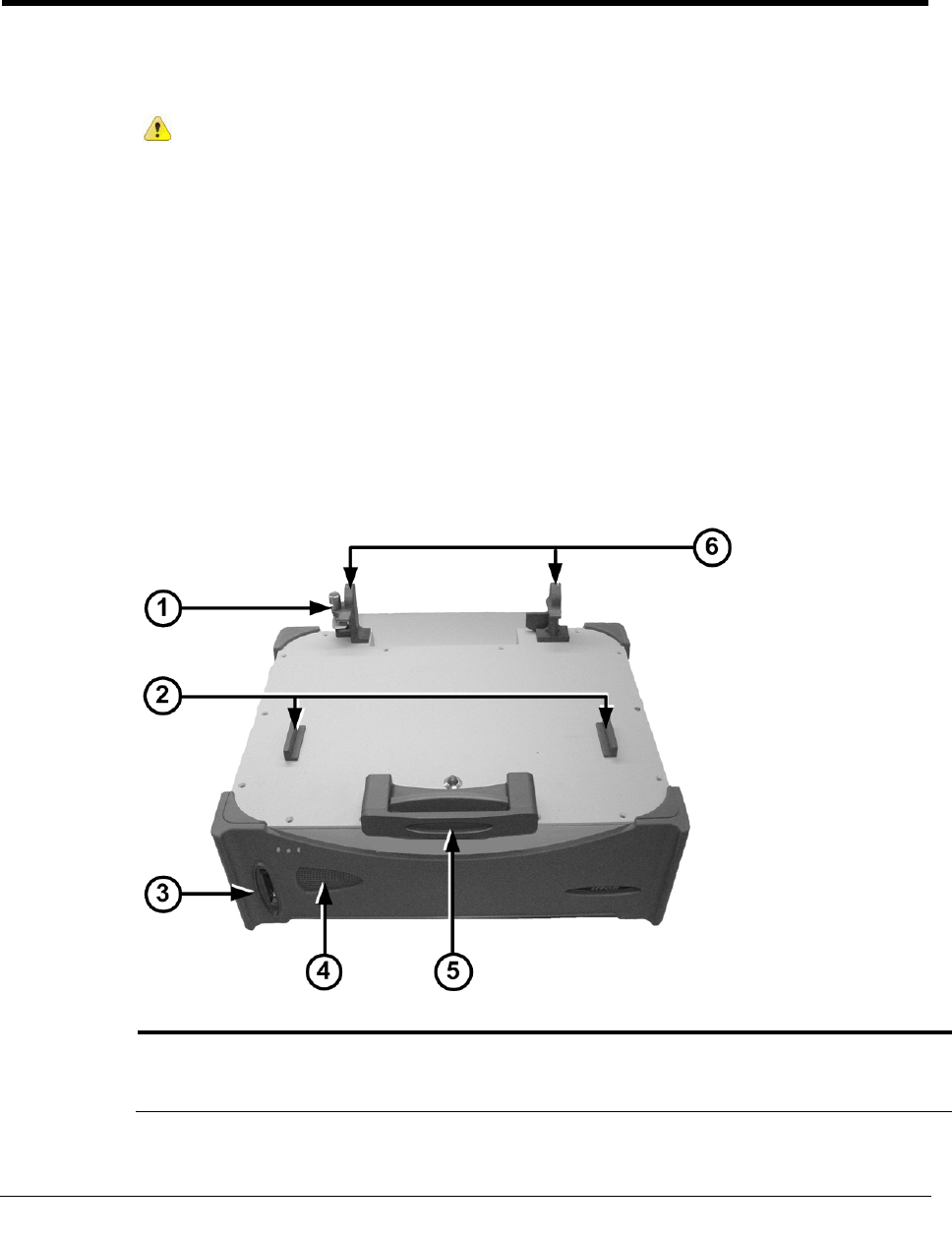
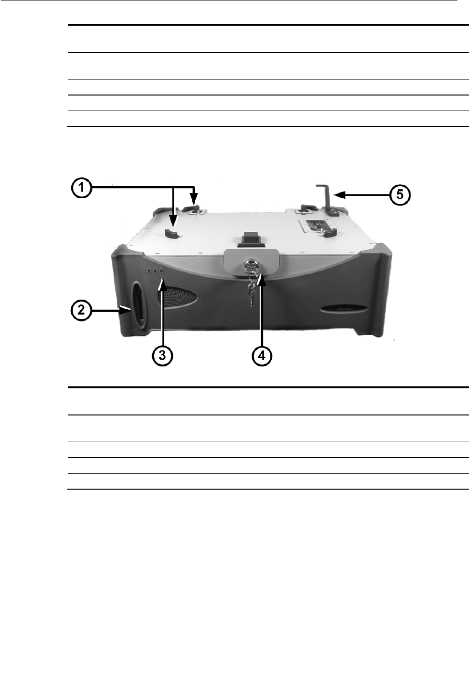
Mobile Collector 2.x Radio - GoBook III
ID
Component
Description
1 USB cable clip Secures the USB cable that connects the GoBook III to the Mobile
Collector radio. The cable clip prevents the USB cable from coming
loose while driving a route.
CHAPTER 2
Using the Mobile Collection 2.x System
Chapter 2 Using the Mobile Collection 2.x System
32 Mobile Collection Hardware Installation Guide
Proprietary and Confidential
ID Component Description
2 Mounting guides Hold the GoBook in place, and assist you in placing the GoBook on
the radio in the proper location.
3 Flash card reader Provides data backups when configured through the Mobile
Administration function.
4 LEDs Indicate system power, operation, and flash card status.
5 Locking mechanism Secures the GoBook to the top of the radio.
6 Screen rests Provide support for the GoBook III screen.
Mobile Collector 2.x Radio - GoBook MAX
ID Component Description
1 Mounting guides Hold the GoBook in place and assist you in placing the GoBook on
the radio in the proper location.
2 Flash card reader Provides data backups when configured through the Mobile
Administration function.
3 LEDs Indicate system power, operation, and flash card status.
4 Locking mechanism Secures the GoBook to the top of the radio.
5 Screen rest Provides support for the GoBook MAX screen.
Flash Card Reader
Route data can be transferred to and from the Mobile Collector using a removable flash
card (two CompactFlash® cards are supplied). The Windows operating system on the
GoBook recognizes the flash card as a removable drive, allowing standard file access.
Periodic data backups to the flash card can be configured in the Mobile Administration
application. See the Mobile Collection Administration Guide (TDC-0381-001) or Online
Help for more information.

About the Mobile Collection 2.x System
Mobile Collection Hardware Installation Guide 33
Proprietary and Confidential
See the Mobile Collection User's Guide (TDC-0380-xxx) or Online Help for more
information on using the flash card in day-to-day activities.
Compact Flash Cards
The Mobile Collection system includes two SanDisk® CompactFlash cards. If you
require more cards, you may purchase them through Itron or through electronics stores or
distributors.
Caution Use of unapproved cards can result in loss of data.
If you purchase additional cards from a distributor or electronics retailer, Itron
recommends the following:
• 64M SanDisk Industrial Grade, Extended Temperature range.
• 64M Hitachi Renesas, Industrial Grade, Wide Temperature, or Extended Temperature
range.
LEDs
Three LEDs signal system power, system operation, and flash card status. Errors relating
to the transmitter and receivers display on the GoBook within the Mobile Interface.
The table below describes the LED status indicators.
LED
Color
Description
Power/Error 1
Red Voltage error condition
Flashing Green Vehicle accessories power on, ignition off
Green Vehicle ignition on
None System is shutting down or completely off
Operate/Error 2
Red Temperature error condition
Green Operating normally
None System is shutting down or completely off
Flash Card
Red Data transferring to/from the flash card reader
None System is shutting down or completely off
Locking Mechanism - (GoBook)
The locking mechanism attaches the GoBook to the Mobile Collector. Locking the
GoBook to the Mobile Collector reduces the likelihood of the GoBook separating from
the Mobile Collector in the event of a collision.
The GoBook MAX has a keyed locking mechanism; the GoBook III has a keyless locking
mechanism.
Chapter 2 Using the Mobile Collection 2.x System
34 Mobile Collection Hardware Installation Guide
Proprietary and Confidential
Warning Do not set down the Mobile Collector on its front face while carrying it
by the handle or at any time. Doing so may damage the flash card reader or the
flash card, or may break off the key if it was left in the mounting lock.
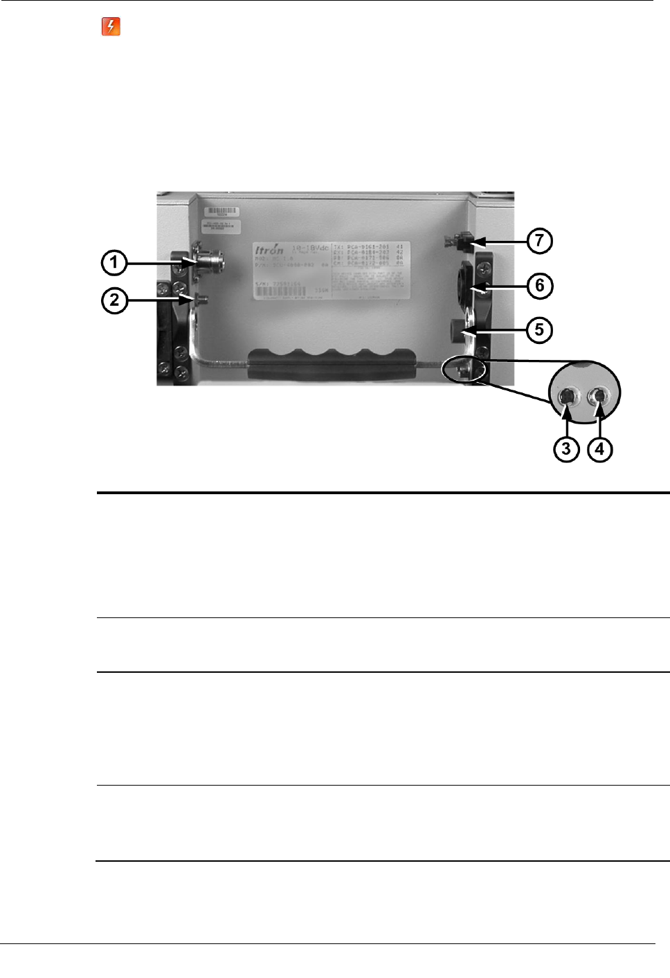
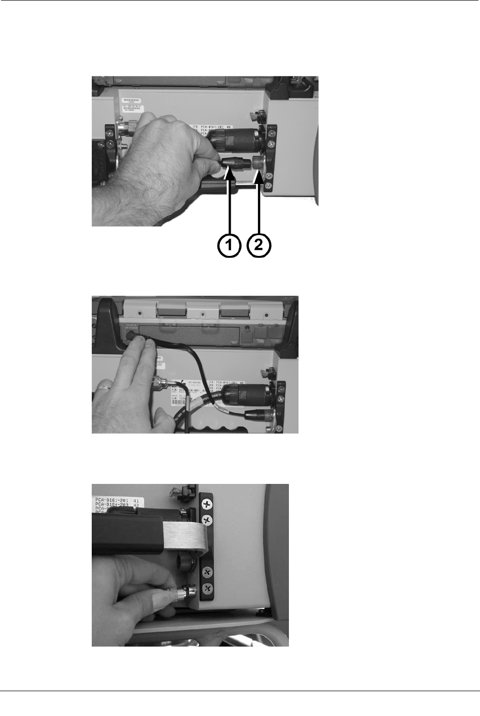
Rear Connectors
The rear of the Mobile Collector 2.x radio contains the power and communications
connectors.
ID Connector Description
1 RF antenna Connects to the roof-mounted antenna. See the Mobile Collection
Vehicle Preparation Guide for more information.
Itron provides a magnetic mount option for the RF antenna. This
magnetic mount is intended as a temporary solution and it is for
emergency use only. Long-term use of a magnetic mount antenna
could adversely affect system performance and is not a supported
configuration of this product.
2 GPS antenna Connects to the externally-mounted GPS antenna. This gold-plated
connector is used with the optional Mapping feature of the Mobile
Interface software.
3 USB Connects the GoBook III computer to the radio for data transfer.
Also for use with a GoBook computer not mounted directly to the
Mobile Collector radio. See Vehicle Dock / Pedestal Option on page
36 for more information.
Mobile Collector radios for use with the GoBook MAX have a USB
data connection built into the radio lid.
4 GPS receiver Connects to an external GPS receiver box when using a version 2.0
radio.
Version 2.5 radios have a GPS receiver built into the Mobile
Collector. This connector is not used with a 2.5 radio.
GoBook Mounting Systems
Mobile Collection Hardware Installation Guide 35
Proprietary and Confidential
ID Connector Description
5 GoBook III power Provides power to the GoBook III laptop.
Mobile Collector radios for use with the GoBook MAX have a
power connection built into the radio lid.
6 Power in Procides 12V DC power from the vehicle's power outlet to the radio
and GoBook.
In addition to wiring the power cable directly to the vehicle, a 12V
auxiliary power cable is available for emergency use only. Using this
cable will disable the power management functions of your Mobile
Collector and could adversely affect system performance.
Caution ALWAYS disconnect this cable from the power source
when not in use. Failure to do so could result in a dead vehicle
battery.
7 Fuse holder and fuse
Provides power surge protection for the radio. The fuse holder uses a
standard 12V 15A fuse (included).
Mobile Collector Sled
The Mobile Collector sled is a mounting bracket designed to secure and support the
Mobile Collector and the GoBook on the passenger seat in an upright position.
GoBook Mounting Systems
The GoBook mounting system provides two options:
• Direct Mount. The GoBook mounts directly on the Mobile Collector.
• Vehicle Dock / Pedestal. (Optional) The GoBook mounts on the vehicle dock
attached to a free-standing pedestal.
The Itronix documentation refers to the laptop receptacle as a cradle; Itron uses the
term dock to identify this piece of equipment. The term dock is used repeatedly
throughout this manual; however, dock and cradle are interchangeable.

Chapter 2 Using the Mobile Collection 2.x System
36 Mobile Collection Hardware Installation Guide
Proprietary and Confidential
Warning Improperly installed or secured components may result in injury or
death in the event of a collision. Install and secure the system components in
accordance with this document, the Mobile Collection Vehicle Preparation
Guide, the Mobile Collection Sled and Pretensioner Installation Guide,
manufacturer installation instructions, and applicable safety standards.
Direct Mounting Options
• GoBook. Communicates with the Mobile Collector, which provides 12V DC power,
quick release connections through the mounting connector, and easy docking without
additional cables.
• GoBook MAX. Mounts onto the Mobile Collector radio within the mounting guides
so that the mounting connector and the external modem connector insert into mating
connectors on the underside of the GoBookMAX. A key inserted into the locking
mechanism turns clockwise to lock the GoBookMAX in place.
• GoBook III. Mounts onto the Mobile Collector radio within the mounting guides,
but communicates through a USB cable and is powered from a cable connected to the
Mobile Collector.
Vehicle Dock / Pedestal Option
Optionally, you can mount the GoBook on a vehicle dock that is attached to a pedestal.
This option allows you to position the GoBook in the vehicle so that it is closer to the
driver, while placing the Mobile Collector radio and its base elsewhere in the vehicle. A
key inserted into the locking mechanism turns clockwise to lock the GoBook MAX in
place. A similar mechanism will be available for use with the GoBook III.
XR-1 and Toughbooks must be mounted to a vehicle dock that is attached either to a
pedestal or a second sled.
Installing the Mobile Collection 2.x System
This section describes how to properly install a Mobile Collection 2.x system with either a
GoBook III or a GoBook MAX.
Attach the Mobile Collector 2.x to the Sled
A plate installed beneath Mobile Collector contains holes and slots that mate with the pins
on top of the sled. Attach the Mobile Collector to the sled by lowering it onto the pins and
rotating it so that the pins slide into the slots, locking the Mobile Collector in place.
Installing the Mobile Collection 2.x System
Mobile Collection Hardware Installation Guide 37
Proprietary and Confidential
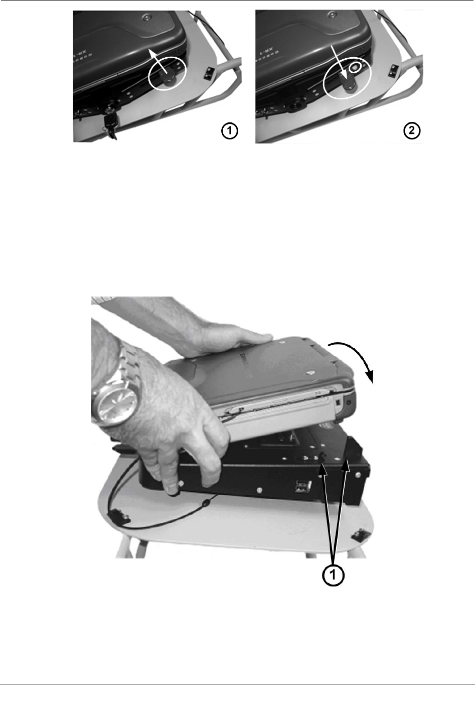
To attach the Mobile Collector to the sled
1. Hold the Mobile Collector over the base and orient it so that the right rear corner
faces the passenger door.
2. Lower the Mobile Collector onto the sled and gently move it around until the center
pin on the base snaps into the center hole on the underside of the Mobile Collector.
3. While gently applying downward pressure, rotate the collector back and forth slightly
until the three pins on the base fit into the three matching holes on the underside of
the Mobile Collector.
4. Grip two corners of the Mobile Collector that are opposite each other diagonally and
rotate it counter-clockwise until you hear the locking pin snap into the underside of
the Mobile Collector.
Chapter 2 Using the Mobile Collection 2.x System
38 Mobile Collection Hardware Installation Guide
Proprietary and Confidential
When finished, the rear of the Mobile Collector should be flush with the side of the
base and its rear connectors should face the passenger door.
Connect the Antennas and Power Cables
The RF antenna, GPS antenna, and Mobile Collector power cable should be pre-installed
in the vehicle and routed to where the Mobile Collector will be installed.
The GPS system for version 2.x Mobile Collectors is an optional component that is
part of the Mapping system. If your installation does not include Mapping, simply
attach the RF antenna and the power cable in the procedure below; ignore the steps
related to the GPS antenna.
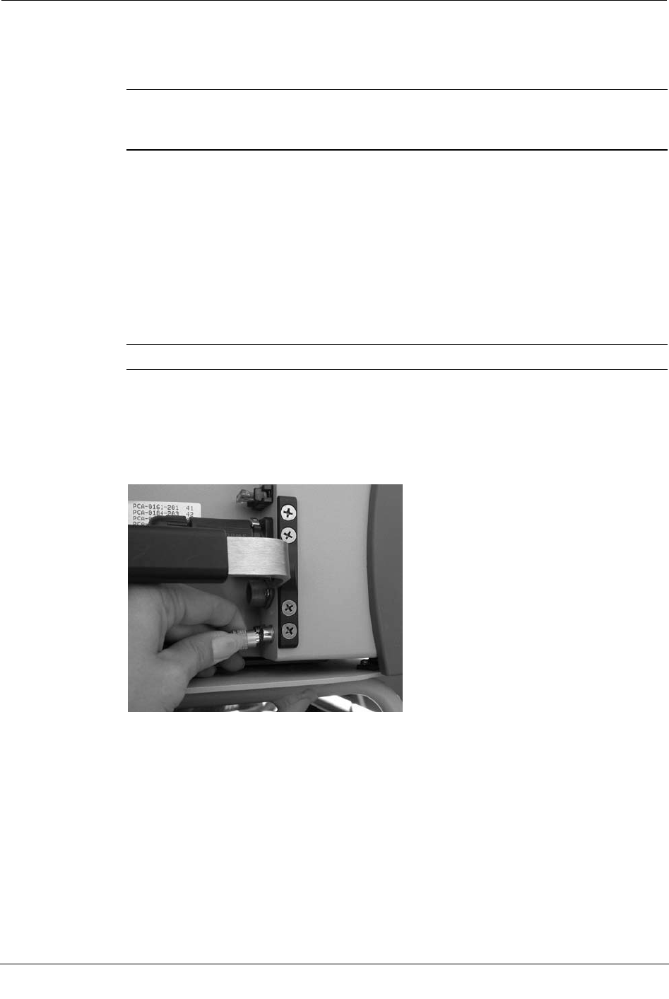
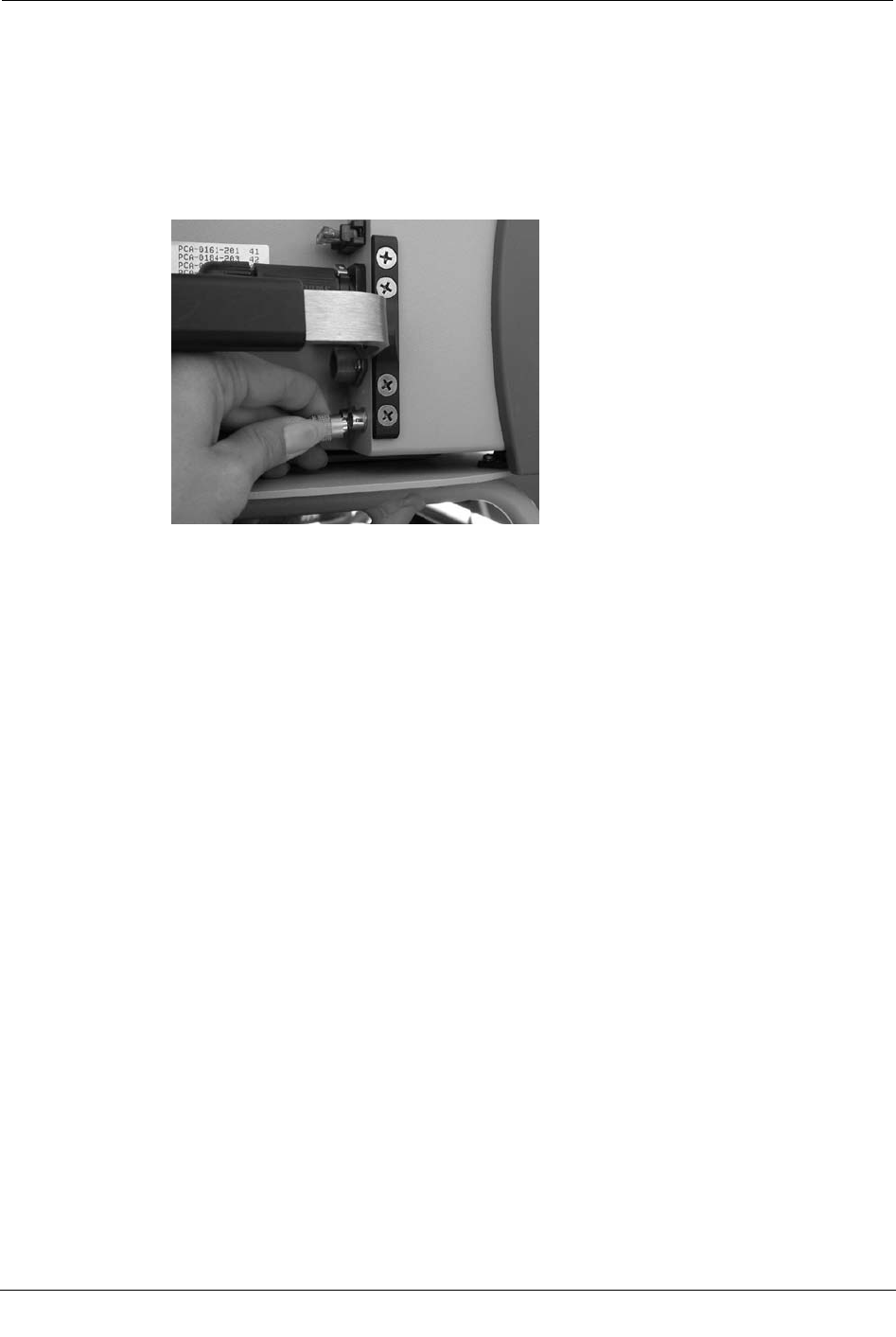
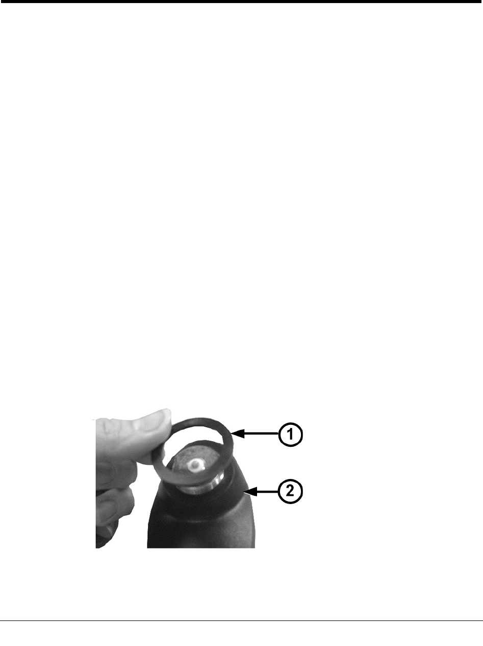
To connect the antennas and power cables
1. Plug the power cable (1) into the power connector on the Mobile Collector.
2. Attach the pre-wired RF antenna cable (2) and turn the knurled part of the antenna
cable clockwise until the cable is firmly attached.
Installing the Mobile Collection 2.x System
Mobile Collection Hardware Installation Guide 39
Proprietary and Confidential
Note If the power cable does not reach the Mobile Collector, use the optional
extension cable to extend the length (extension cables may be purchased from Itron).
Install the power cable in line between the extension cable and the Mobile Collector.
Ensure that both cable ends are connected securely to each connector.
3. Attach the GPS cable to the connector. Both the end of the cable and the connector
are gold-plated for easy identification.
Attach the GoBook to the Mobile Collector 2.x
This section describes how to connect the Mobile Collection laptop to the Mobile
Collector radio.
The GoBook III and GoBook Max can attach directly to the Mobile Connector radio or
attach to a vehicle cradle mounted on a pedestal by the driver (for more information, see
GoBook Mounting Systems on page 35). The GoBook XR-1 and Panasonic Toughbook
are pedestal or sled dock mount only.
To attach the GoBook to the Mobile Collector, follow the steps in one of the following
sections:
GoBook MAX Procedures
GoBook III Procedures
Attach the GoBook MAX to the Mobile Collector on
page 39 Attach the GoBook III to the Mobile Collector on page
40
Attach the GoBook MAX to the Vehicle Dock on page
42 Attach the GoBook III to the Vehicle Dock on page 42
To attach the GoBook MAX to the Mobile Collector
1. Ensure that the Mobile Collector's locking mechanism is unlocked.
2. From the driver’s side of the vehicle, align the GoBook MAX with the four mounting
guides on top of the Mobile Collector.
3. Angle the top of the GoBook MAX towards the passenger door (as shown below),
and lower it so that the two rear connectors (1) on the Mobile Collector top fit into the
mating holes on the GoBook MAX underside.
Chapter 2 Using the Mobile Collection 2.x System
40 Mobile Collection Hardware Installation Guide
Proprietary and Confidential
4. Lower the GoBook MAX onto the Mobile Collector within the mounting guides (2)
until the underside of the GoBook MAX is flush with the top of the Mobile Collector.
If necessary, gently move the GoBook MAX slightly from side to side to ensure the
connectors on top of the Mobile Collector mate with those on the underside of the
GoBook MAX.
5. Insert the key into the mounting lock and press the locking mechanism so it secures
the GoBook Max to the Mobile Collector.
6. Turn the key clockwise to lock the GoBook MAX in place.
7. Remove the key from the lock so that it is not stolen or accidently broken.
8. Lift the GoBook MAX screen up and gently push it back so that it rests on the Mobile
Collector screen rest.
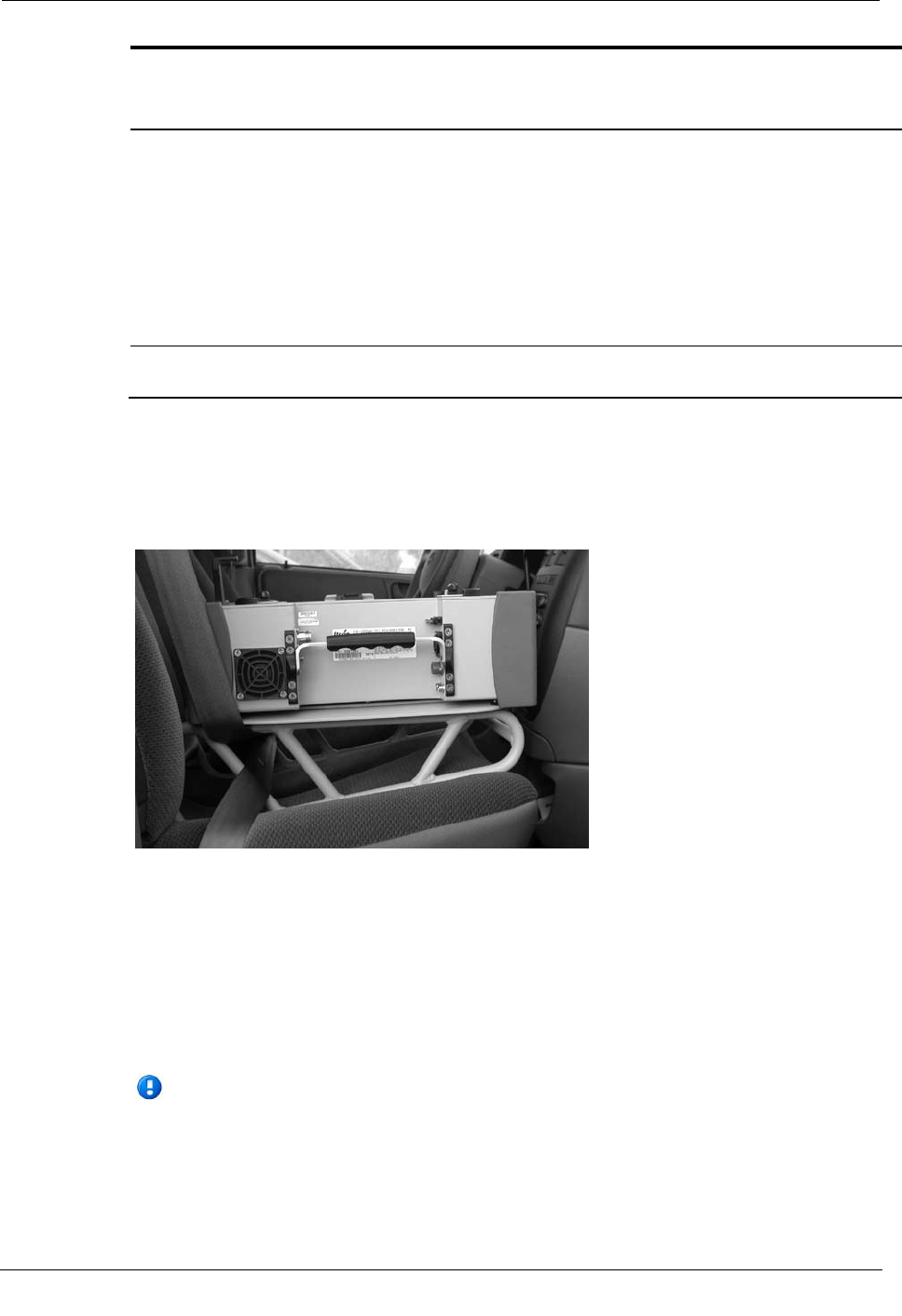
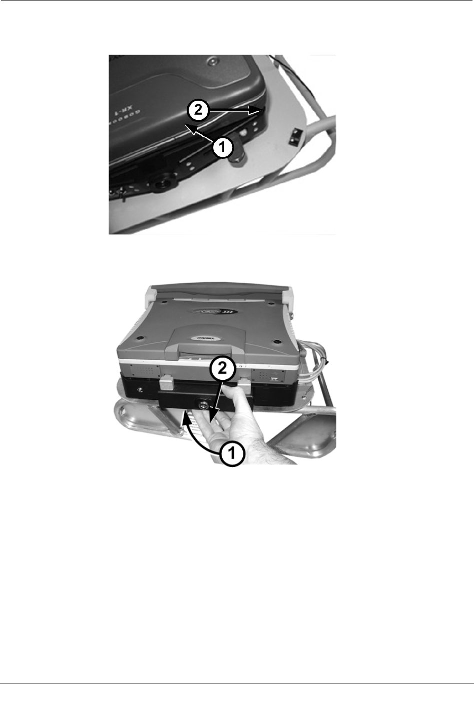
Attach the GoBook III to the Mobile Collector
1. From the driver’s side of the vehicle, align the GoBook III with the two mounting
guides (1) on top of the Mobile Collector.
Installing the Mobile Collection 2.x System
Mobile Collection Hardware Installation Guide 41
Proprietary and Confidential
2. Angle the GoBook III towards the passenger door, as shown below, and slide it under
the mounting guides (1) toward the back of the Mobile Collector.
3. Lower the GoBook III onto the Mobile Collector between the mounting guides until
the underside of the GoBook III is flush with the top of the Mobile Collector.
If necessary, gently move the GoBook III slightly from side to side to ensure the
connectors on top of the Mobile Collector mate with those on the underside of the
GoBook III.
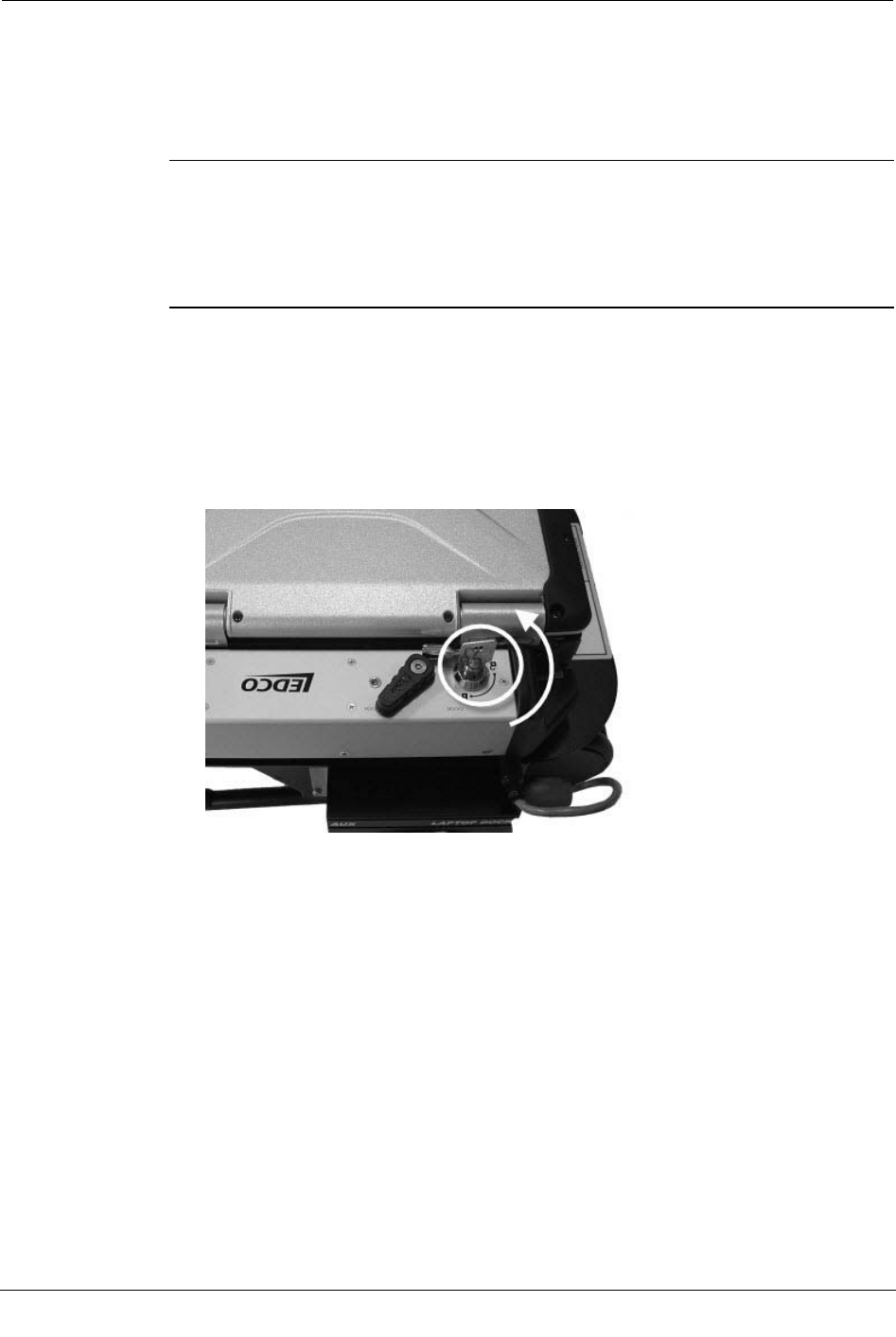
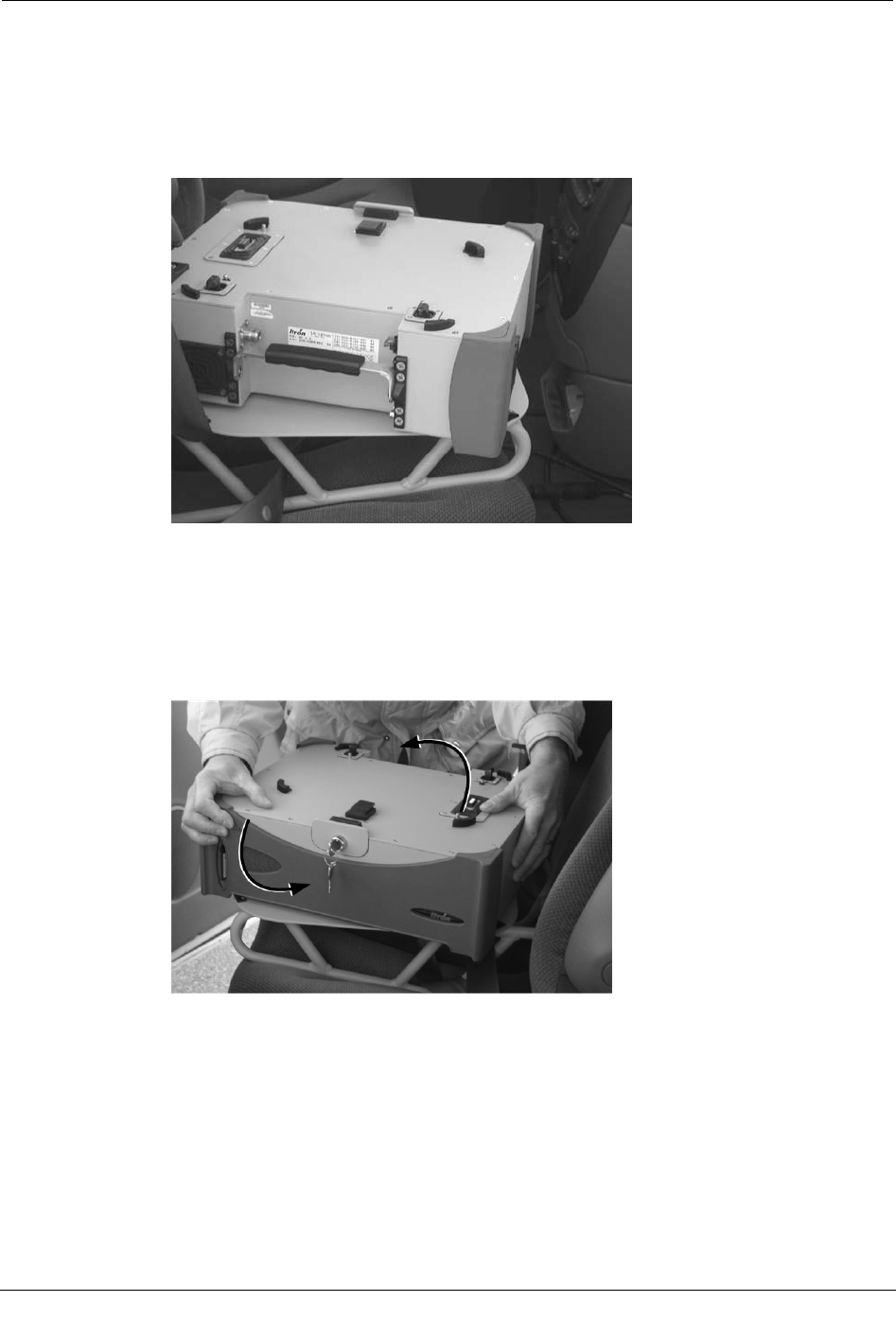
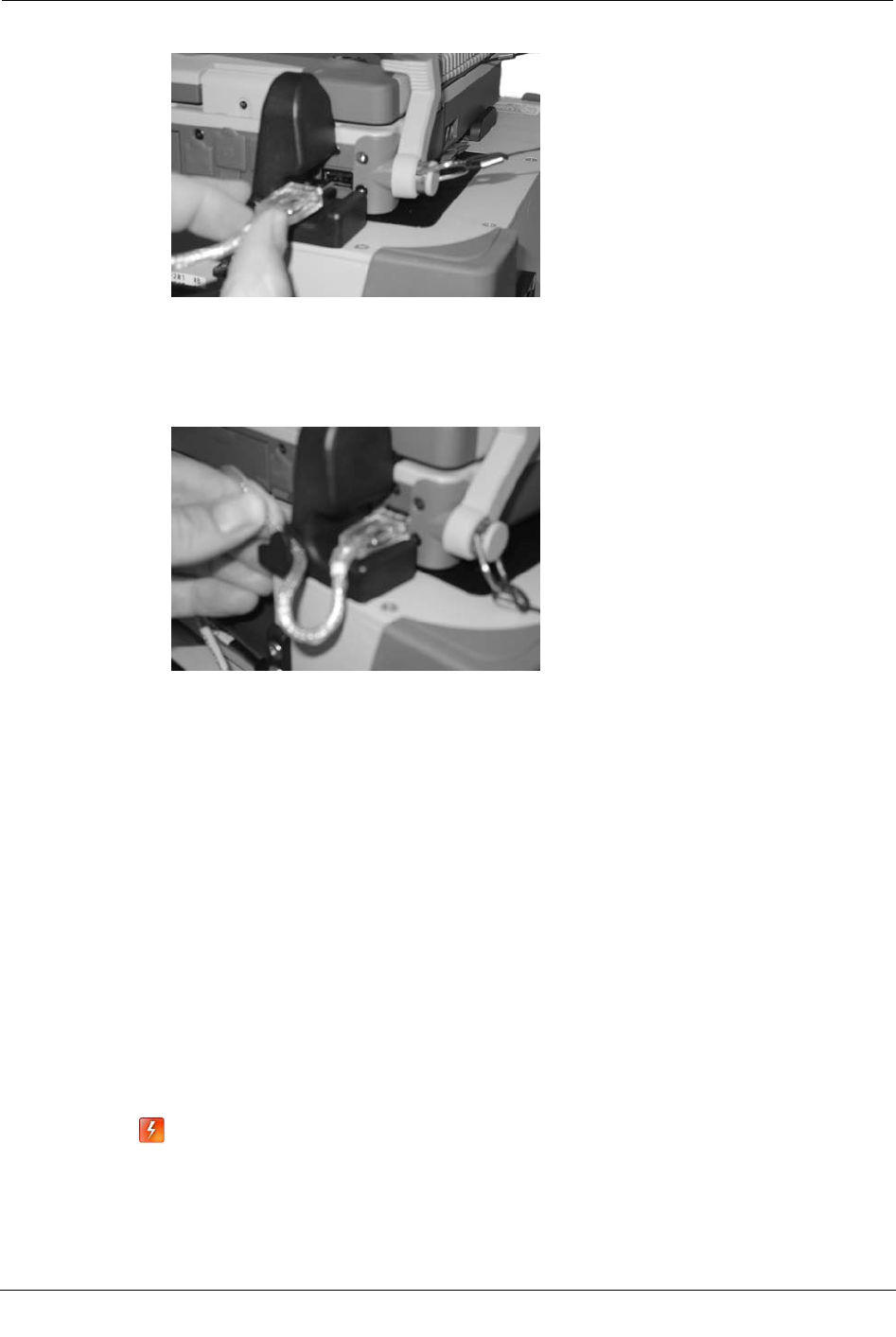
4. With one hand, pull on the locking mechanism to release it. With the other hand,
gently push down on the top of the GoBook III, as shown below.
5. Release the locking mechanism to lock the GoBook III in place.
6. Attach the necessary USB and power cables from the Mobile Collector to the
GoBook III.
7. Secure the USB cable in place by tightening the metal cable clip.
8. Lift the GoBook III screen up and gently push it back so that it rests on the Mobile
Collector screen rest.
Chapter 2 Using the Mobile Collection 2.x System
42 Mobile Collection Hardware Installation Guide
Proprietary and Confidential
To attach the GoBook MAX to the vehicle dock
1. Ensure that the vehicle dock is installed properly. If required, refer to the Itronix
Vehicle Cradle Installation Guide for detailed instructions.
Note The Itronix documentation refers to the laptop receptacle as a cradle. Itron uses
the term dock to identify this piece of equipment. The term dock is used repeatedly
throughout this manual; however, dock and cradle are interchangeable.
2. Angle the top and center of GoBook MAX on the vehicle dock mounting guides, then
lower it so that the two rear locking mechanisms on the vehicle dock top fit into the
mating holes on the GoBook MAX underside.
3. Lower the GoBook MAX onto the vehicle dock within the mounting guides until the
underside of the GoBook MAX is flush with the top of the vehicle dock.
4. Insert the key into the mounting lock.
5. Press the locking mechanism so it engages the GoBook MAX.
6. Turn the key clockwise to lock the GoBook MAX in place.
Note Remove the key from the lock so that it is not accidently broken or stolen.
7. Plug the vehicle dock cable into a vehicle dock USB port. Two USB ports are located
on the back of the vehicle dock.
8. Plug the vehicle dock cable into the Mobile Collector radio by pulling the connector
sleeve back, plugging the connector in to the Mobile Collector as shown, and
releasing the sleeve.
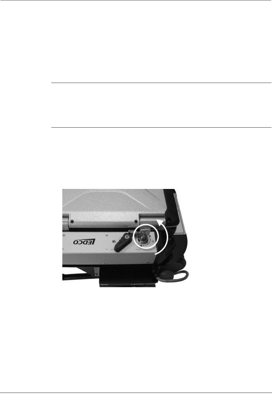
Attach the GoBook III to the Vehicle Dock
1. Ensure that the vehicle cradle is installed properly. If needed, refer to the Itronix
Vehicle Cradle Installation Guide for detailed instructions.
2. Lower the GoBook III onto the vehicle dock.
Be sure to align it within the front and read guides on the dock. The front of the
laptop should face the locking mechanism on the front of the dock.
3. Push in the handle on the front of the dock to engage the locking mechanism and
secure the GoBook to the dock.
Installing the Mobile Collection 2.x System
Mobile Collection Hardware Installation Guide 43
Proprietary and Confidential
4. Push in the keyed part of the locking mechanism to further lock it and prevent theft of
the laptop.
5. Plug one end of the vehicle dock USB cable into one of the two available ports on the
back of the vehicle dock. The port uses a standard USB connector.
6. Plug the vehicle dock USB cable into the USB port on the Mobile Collector by
pulling the connector sleeve back, plugging the connector in to the Mobile Collector,
and releasing the sleeve.
To attach the GoBook XR-1 to the vehicle dock
See To attach the GoBook XR-1 to the vehicle dock on page 10.
To attach the Toughbook to the vehicle dock
See To attach the Toughbook to the vehicle dock on page 7.
Connect the GoBook III Power Supply and USB Cable
The GoBook III receives power from the Mobile Collector radio through a simple power
cable connection. In Mobile Collection system versions that use a GoBook MAX, the
power and data connections are integrated into the top of the Mobile Collector radio.
For the GoBook III, additional cables must be attached to provide the laptop with power
and a data connection. The USB cable is used to provide data collected by the Mobile
Collector radio to the Mobile Interface application running on the GoBook III.
Chapter 2 Using the Mobile Collection 2.x System
44 Mobile Collection Hardware Installation Guide
Proprietary and Confidential
To connect the GoBook III power supply and USB cables
1. Attach the end of the GoBook III power cable (1) to the blue connector on the back of
the Mobile Collector radio (2). This connector is located beneath the main power
supply.
2. Attach the other end of the power cable to the connector on the back of the GoBook
III.
3. Plug the USB cable into the Mobile Collector radio by pulling the connector sleeve
back, plugging the connector in to the Mobile Collector as shown, and releasing the
sleeve.
Installing the Mobile Collection 2.x System
Mobile Collection Hardware Installation Guide 45
Proprietary and Confidential
4. Connect the USB cable to the back of the GoBook III, as shown below.
5. Route the USB cable through the channel on the back of the Mobile Collector radio
mounting guide. Press the cable down into the channel to make sure it is secure.
This process ensures that the GoBook III can communicate with the Mobile Collector
radio while you are driving a route.
Flash Card Used in Mobile Collector 2.x Systems
You can import route files to the Mobile Interface database and export the collected data
using a removable flash card in the Mobile Collector flash card reader.
The default drive letter for the flash card reader varies depending on which of the
following two GoBooks your Mobile Collection system uses:
• GoBook Max. The card reader defaults to drive F:.
• GoBook III. The card reader defaults to any of the following drives: G:, H:, or I:.
The actual letter used varies depending on which various peripherals are connected to
the system.
Always ensure you are accessing the proper drive.
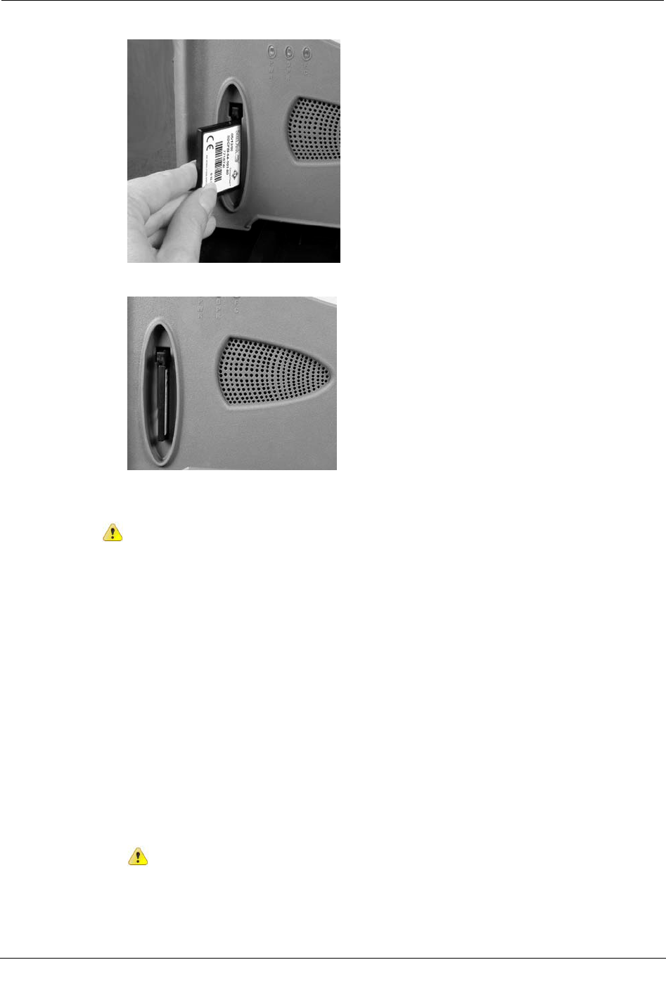
Insert the Flash Card
Warning If you do not hold the flash card correctly, the flash card will not insert
into the reader. Forcing the flash card into the reader can damage the connector
pins.
Chapter 2 Using the Mobile Collection 2.x System
46 Mobile Collection Hardware Installation Guide
Proprietary and Confidential
1. Insert the flash card into the reader slot, as shown.
2. Press the flash card firmly into the reader until the eject button pops out.
To remove the flash card
Caution Before removing the flash card, shut down the GoBook. Failure to do so
could result in data loss on your flash card.
1. Shut down the GoBook.
2. Press the eject button on the flash card reader.
3. Gently pull the flash card out of the flash card reader slot.
Removing the Mobile Collection 2.x System
At some point, you may need to remove the Mobile Collection system from the vehicle.
Removing the Mobile Collection System is a three step process:
1. Remove the Mobile Collection laptop from the vehicle dock.
2. Disconnect the cables from the Mobile Collector radio.
3. Remove the Mobile Collector from the sled.
Before removing any Mobile Collection system components be sure to stop the
Mobile Interface and shut down the Mobile Collection laptop.
Removing the Mobile Collection 2.x System
Mobile Collection Hardware Installation Guide 47
Proprietary and Confidential
To remove the Mobile Collection laptop from the vehicle dock
1. In the Mobile Interface software stop processing reads.
2. Complete routes.
3. Export routes.
4. Shut down all open applications.
5. Shut down the Mobile Collection laptop.
6. Close the Mobile Collection laptop screen.
Caution If you accidentally disconnect the Mobile Collection laptop from the MC3
radio before shutting down Windows and the laptop, the following message appears:
Unsafe Removal of Device
Before clicking OK, clear the ShowUnplug/Eject icon on the Taskbar box. If you do
not clear this box, you will not be able to properly shut down the system in the future.
7. Turn off the vehicle.
8. Disconnect any cables attached directly to the Mobile Collection laptop.
9. If unlocking the Mobile Collection laptop from the vehicle dock:
• Toughbook. Unlock the dock by inserting the dock key into the dock lock and
turning it counter clockwise until the lock is in the Unlock position. Then switch
the docking mechanism to Unlock.
Chapter 2 Using the Mobile Collection 2.x System
48 Mobile Collection Hardware Installation Guide
Proprietary and Confidential
• GoBook XR-1. Press the locking mechanism in and slide it toward the keys on
front of the dock (1), and then push it in a little further and pull it back to the
starting position to unlock the dock (2).
• GoBook III. Press the bottom of the locking system underneath the locking
mechanism (1) and then pull the handle out (2) as shown.
10. Gently lift the Mobile Collection laptop up and away from the cradle.
To disconnect the cables from the Mobile Collector radio
1. Unplug the cables from the Mobile Collector radio and leave them for the next
installation of a Mobile Collection system, if desired.
2. Verify that all cables are properly disconnected, including the USB, power, and
antenna cables.
To remove the Mobile Collector from the sled
1. From the passenger side of the vehicle, reach underneath the top of the base and
locate the locking pin knob.

Removing the Mobile Collection 2.x System
Mobile Collection Hardware Installation Guide 49
Proprietary and Confidential
2. Use one hand to pull the knob down, and use the other hand to push a corner of the
Mobile Collector in a clockwise direction. Continue pulling the knob down and
pushing until the pin can no longer snap into the underside of the Mobile Collector.
Grip two corners of the Mobile Collector that are opposite each other diagonally and
rotate it clockwise until you cannot rotate it further.
The right rear corner of the Mobile Collector faces the passenger-side door when the
Mobile Collector cannot be rotated further.
3. Lift the Mobile Collector off the base.
4. Unfasten the seat belt and pretensioner and lift the base off the seat.

Chapter 2 Using the Mobile Collection 2.x System
50 Mobile Collection Hardware Installation Guide
Proprietary and Confidential
Mobile Collection Hardware Installation Guide 51
Proprietary and Confidential
This chapter describes some of the basic maintenance procedures that should be
performed regularly to ensure optimal performance of your Mobile Collection system.
RF Antenna Maintenance
To maintain both the performance and the appearance of your omni-mount RF antenna,
regular cleaning is recommended.
To clean the antenna
• Clean the antenna in the same manner as your vehicle. Apply a quality car wax to the
antenna and base to help protect the finish and extend the life of the antenna.
Replacing Gaskets
To maintain the integrity and performance of the antenna, Itron recommends that you
replace the gasket located in the antenna base at least every year. Contact Itron Customer
Support at 1-800-635-8725 for more information. The replacement gasket part number is
MSE-0210-001, which includes six gaskets.
You should inspect the gasket regularly to verify that it is intact, free from debris, and
properly seals the antenna and base.
To replace the antenna gasket
1. Turn the antenna counter-clockwise to remove it from the base.
2. Remove the gasket (1) from the base (2).
3. Place a new gasket on the base and push it firmly into place.
CHAPTER 3
System Maintenance
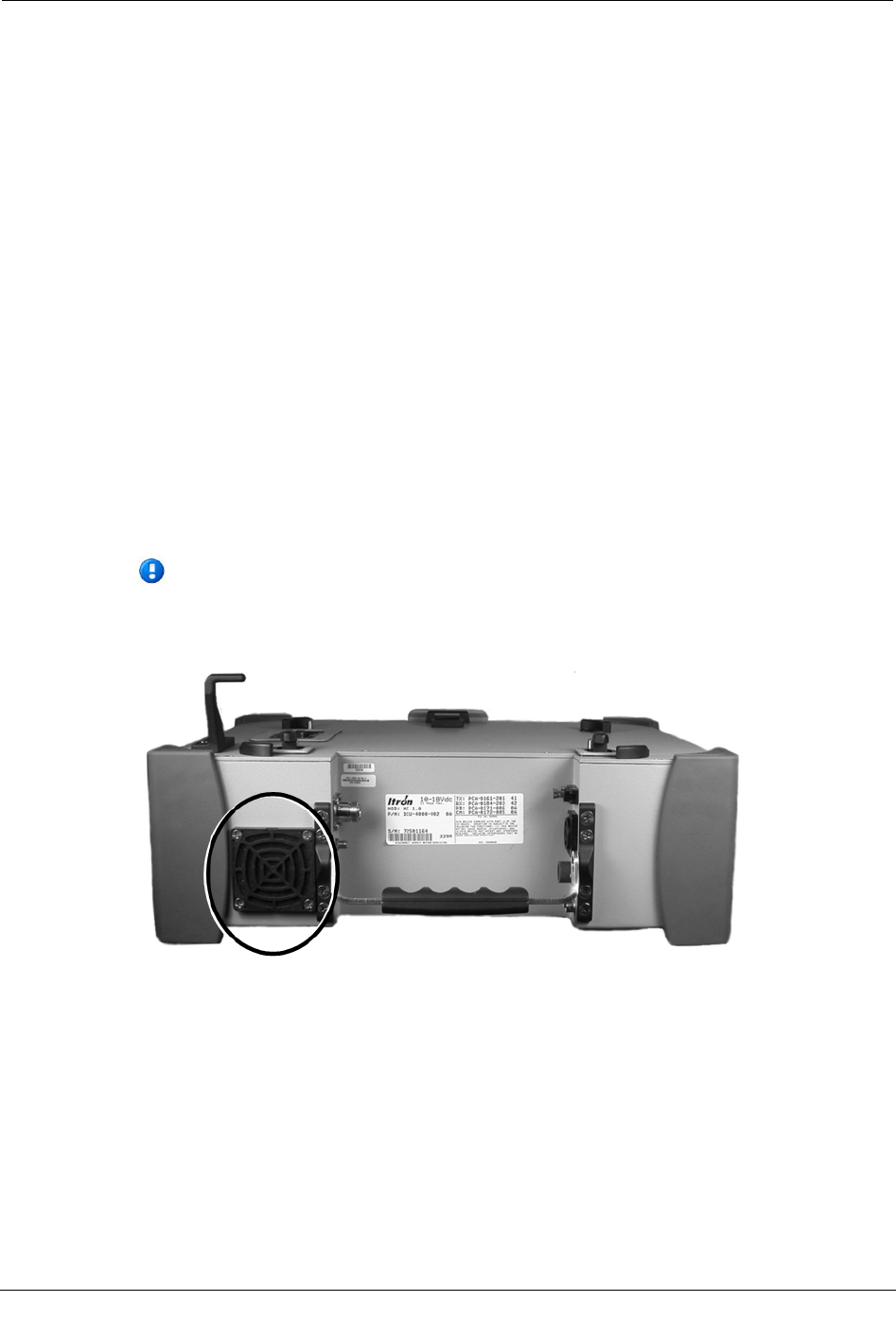
Chapter 3 System Maintenance
52 Mobile Collection Hardware Installation Guide
Proprietary and Confidential
4. Ensure that the gasket is level with the antenna base to prevent pinching when the
antenna is reconnected.
5. Reconnect the antenna to the base by turning it clockwise until it is firmly seated on
the base.
2.x System Maintenance
In addition to the antenna maintenance described earlier, the following tasks should be
performed regularly to keep your Mobile Collection 2.x system operating at peak
performance.
Inspecting and Replacing Filters
The Mobile Collector has two internal fans that circulate air through its components to
cool them. One fan draws air in from the side of the Mobile Collector, while the second
fan blows the air out the rear.
Each fan has a filter accessible externally that requires periodic replacement, depending
on the environment in which the Mobile Collector is operated. To replace the filter, pull
the fan cover off, replace the filter, and snap the fan cover back on.
Inspect the filters regularly and replace them when they become
visibly dirty. Contact an Itron customer service representative to order
replacement filters.
Service Bulletins
The following information is for customers with legacy Mobile Collection systems in
their deployments.
The Service Bulletins listed below should have already been shipped to you, along with
any required hardware updates, but are included here as a reminder and to help you
identify any system components that may need updating.

Service Bulletins
Mobile Collection Hardware Installation Guide 53
Proprietary and Confidential
Mobile Collection 2.5 / GoBook III Power Plug Issue
(Bulletin Issued June 5th, 2006)
In the interest of continuous improvement, Itron has incorporated a reliability upgrade to
your Mobile Collector. The present CBA-0259-002 cable that provides power from the
RF unit to the GoBook III has the conductor exposed on the right angle plug that is
inserted into the GoBook III. With the end of the plug exposed, it is possible to short the
exposed tip on the metal RF chassis. This only happens when power is supplied to the RF
unit before this connection is made between the RF unit and GoBook III. The result of
this shorting condition is damage to a transistor on the power board inside of the RF unit,
which requires your RF unit to be returned to Itron for repair.
To alleviate this problem, we are replacing the existing CBA-0259-002 power plug with
the enclosed CBA-0305-002. CBA-0305-002 has an insulated tip to prevent shorting on
the chassis. Please replace the existing power cable with CBA-0305-002 as soon as
possible and scrap the CBA-0259-002. We also recommend that you always connect the
cable from the RF unit to the GoBook III before you apply power to RF unit.
This improvement is also being made on all new Mobile Collection 2.5 systems being
shipped and all Mobile Collectors when they are returned for service.
If you have any questions, please contact Itron Support at 1.800.635.8725.
Mobile Collector 2.x Power Adapter
(Bulletin Issued September 8th, 2006)
In the interest of continuous improvement, Itron has incorporated a reliability upgrade in
your Mobile Collector. Reliability of the existing power connector has become the
number one cause of Mobile Collector returns during the past year. As a result, we are
replacing the existing power connector with a new power connector that has tested to
have improved reliability and durability.
Along with the new power connector in your RF unit, we have included a new power
cable with new power connectors. It is imperative that you use the new power cable with
your RF unit. The old power cable will not lock into place with the new power connector.
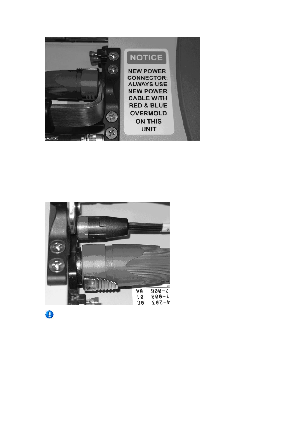
Chapter 3 System Maintenance
54 Mobile Collection Hardware Installation Guide
Proprietary and Confidential
The new power cable was designed to be easily distinguishable from the existing power
cable by placing a red and blue overmold on the connectors. A notice label was placed on
the chassis of the RF unit to remind you of this requirement.
The operation of the new power cable is slightly different from the previous power
connector. To engage the new power connector, align the connector tab with the
connector slot on the RF unit, insert the connector and then rotate clockwise 45 degrees.
To disengage the unit, pull back the locking tab on the cable connector and then rotate the
connector 45 degrees counterclockwise. Notice labels were placed on both ends of your
power cable to remind you how to disengage the new power connector.
If you presently utilize a power cable that plugs into the cigarette lighter, you will
need to contact Itron Support at 1.800.635.8725 to request a replacement cable.
You will be required to send your old cable in as an exchange. It should be noted
that Itron does not recommend the cigarette lighter adapter configuration except
for emergency use.
This change to the new power connector will be incorporated on all new MC2.5 being
shipped and all Mobile Collectors when they are returned for service.
If you have any questions, please contact Itron Support at 1.800.635.8725.