Itron DCU5310U AMR Transceiver Device User Manual Mobile Collection Hardware Installation Guide
Itron, Inc. AMR Transceiver Device Mobile Collection Hardware Installation Guide
Itron >
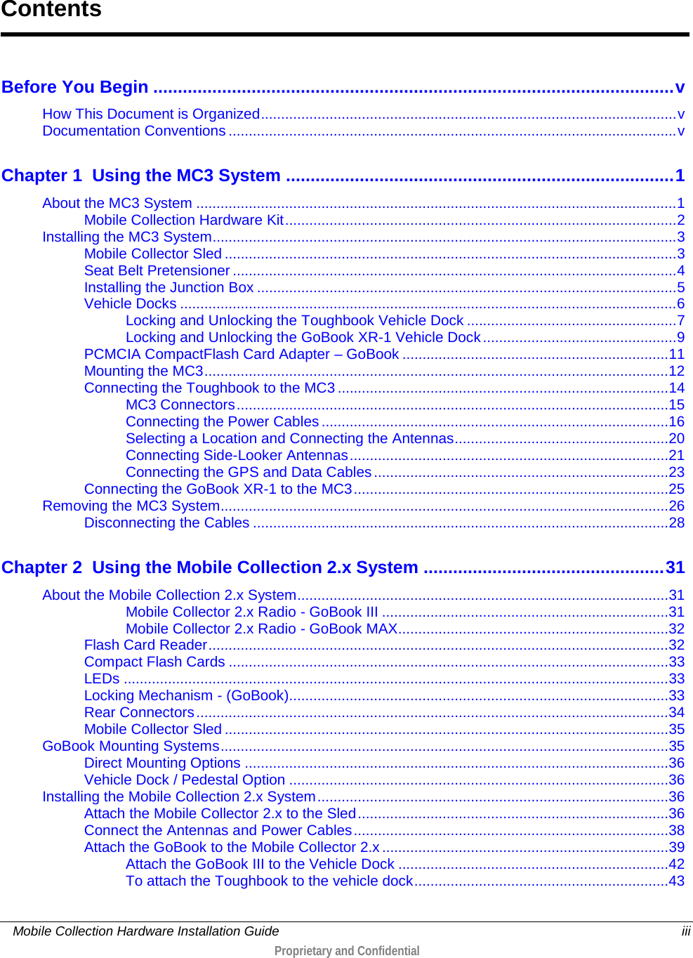
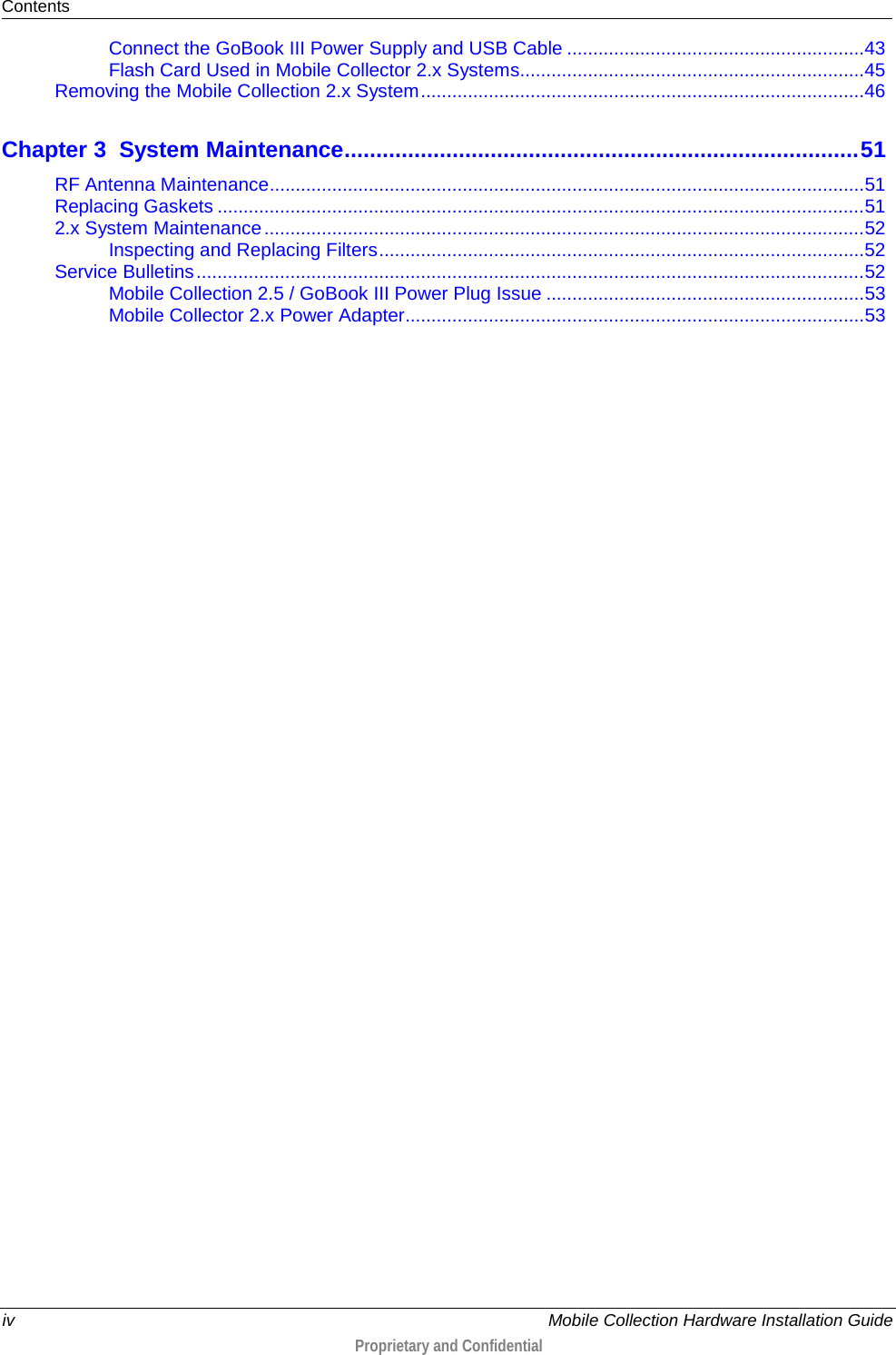
Contents
- 1. Users Manual 1
- 2. Users Manual 2
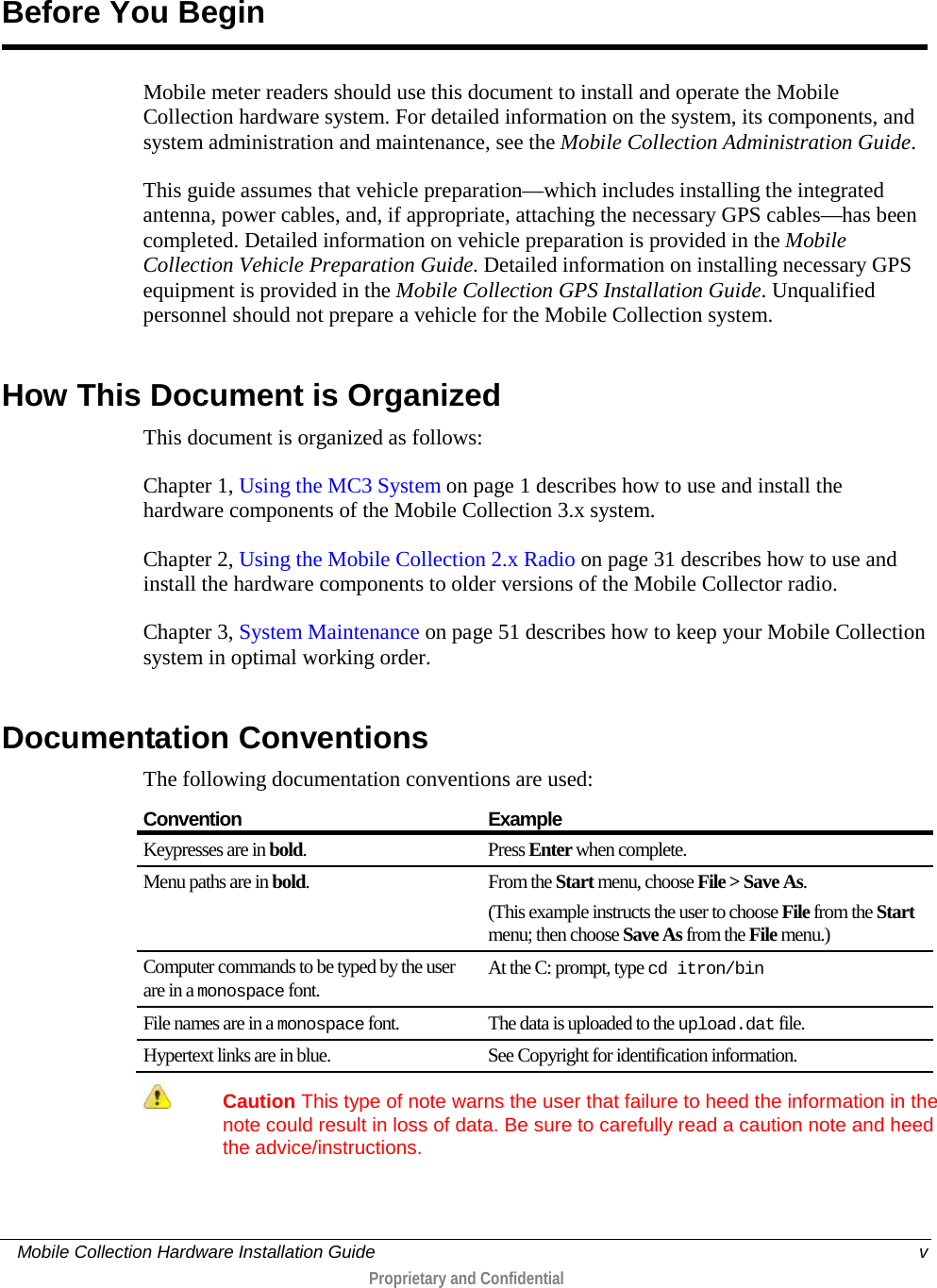
Users Manual 2