Contents
- 1. Users Manual 1
- 2. Users Manual 2
- 3. Users Manual 3
- 4. Users Manual 4
Users Manual 2

DRAFT
Chapter 2 - Repeater Installation 9
TDC-0613-000 10/04
Sleeve-Mount Repeaters
Sleeve-Mount Repeaters
Types of Sleeve-
Mount Sleeve-mount repeater installation depends on the type of meter socket.
Required Tools The following tools are necessary for sleeve-mount repeater installation:
• Tamper seals and associated meter installation/removal tools
• Panduit Wave-Ty installation tool (optional). This tool cuts excess cable
and applies tension to the tension band.
Installing on a
Ringless Meter
Socket
A ringless meter socket does not use a meter seal ring between the meter and the
meter socket. Instead, the meter is secured in the meter socket by a lid. To install
a repeater on a ringless meter socket, do the following steps.
IMPORTANT The following instructions should be considered supplemental to
the meter installation and removal procedures for your utility. Follow all appli-
cable procedures and regulations when performing meter installation.
Meter Socket Type Description
Ringless A ringless mounted meter installs under the meter
box lid, which is hinged at the top of the box.
Ringed A rimmed meter box
Step Action
1Remove tamper seals.
2Verify that the service is compatible with the repeater.
3Remove the meter socket lid.
4Pull the meter from the socket.
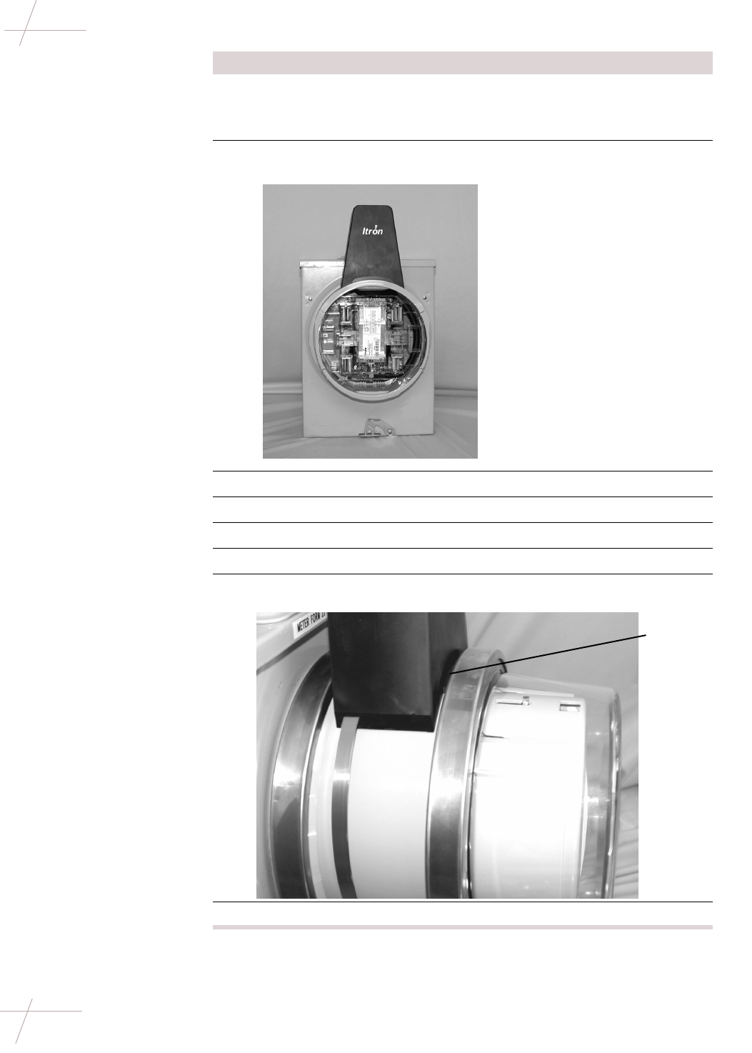
5Insert the repeater into the socket.
DRAFT
10 Fixed Network Repeater Installation Guide
TDC-0613-000 10/04
Sleeve-Mount Repeaters
6Replace the meter socket lid.
NOTE If needed, trim the breakaway rim on the repeater sleeve using
diagonal so that the socket lid will fit over the repeater.
7Place the antenna cover over the antenna on the top of the repeater
sleeve.
8Secure the band around the repeater, pulling to tighten.
9Tighten the tension band using a tension setting tool.
10 Clip off the extra band material.
11 Snap the meter into the repeater socket.
12 Attach the ring making sure to catch the antenna cover lip under the
ring band.
13 Install a tamper seal in the ring band and on the meter socket lid.
Step Action
Catch
cover lip
under ring
DRAFT
Chapter 2 - Repeater Installation 11
TDC-0613-000 10/04
Sleeve-Mount Repeaters
Installing on a
Ringed Meter Socket A ringed meter socket uses a meter sealing ring to secure the meter to the socket.
To install a repeater on a ringed meter socket, do the following steps.
Step Action
1Remove tamper seals.
2Verify that the service is compatible with the repeater.
3Remove the meter seal ring.
4Pull the meter from the socket.
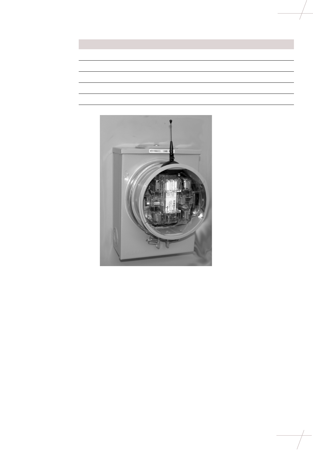
5Insert the repeater sleeve into the meter socket.
6Secure a meter seal ring between the repeater and the meter socket.
DRAFT
12 Fixed Network Repeater Installation Guide
TDC-0613-000 10/04
Sleeve-Mount Repeaters
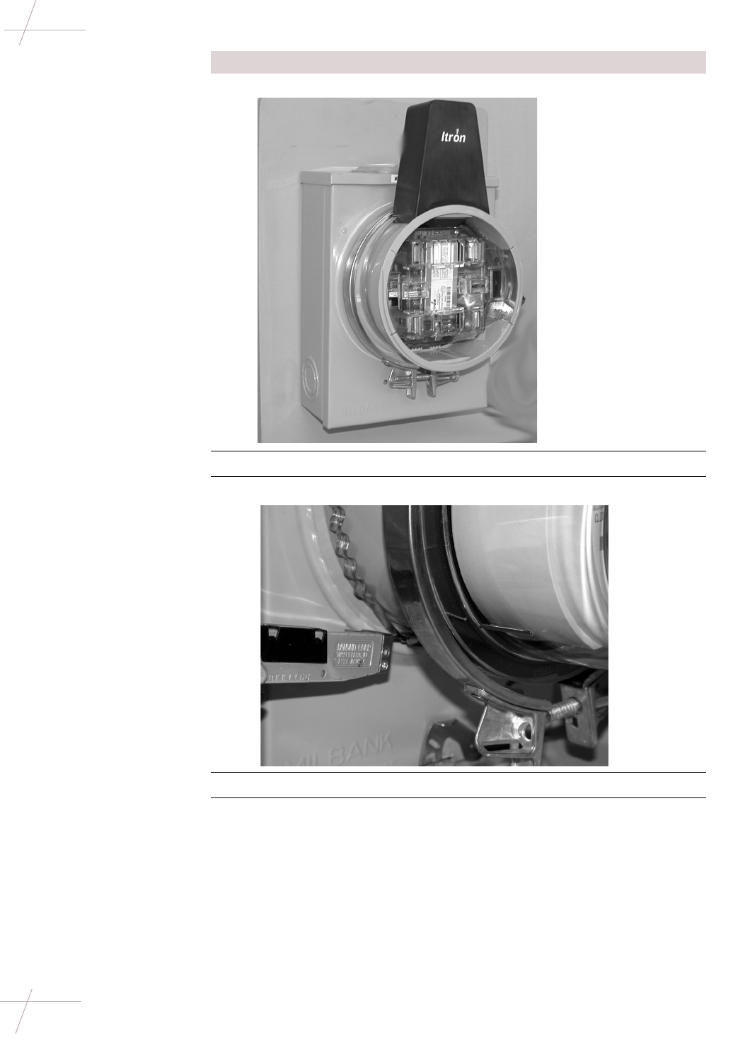
7Place the antenna cover over the antenna on the top of the repeater.
8Secure the antenna cover band around the repeater, pulling to tighten.
9Tighten the tension band using a tension setting tool.
10 Clip off the extra band material.
11 Insert the meter into the repeater socket.
Step Action

DRAFT
Chapter 2 - Repeater Installation 13
TDC-0613-000 10/04
Sleeve-Mount Repeaters
12 Attach the meter seal ring making sure to catch the antenna cover lip
under the ring band.
13 Replace the tamper seals.
Step Action
Catch
cover lip
under ring

DRAFT
14 Fixed Network Repeater Installation Guide
TDC-0613-000 10/04
Sleeve-Mount Repeaters
DRAFT
Chapter 3 - Repeater Configuration 15
TDC-0613-000 10/04
Chapter 3
Repeater Configuration
Getting Started
Overview Repeater configuration and troubleshooting is performed in the field using two
components:
•Repeater Programmer communicates with repeaters and endpoints. You
can use the programmer in the field to troubleshoot repeater problems and
optimize network performance. The programmer is connected to your
computer using a serial cable and powered by a 5 volt power cord.
•Itron QuickTerminal is a terminal emulation application, similar to Hyper-
Terminal or ProComm.
Navigating in
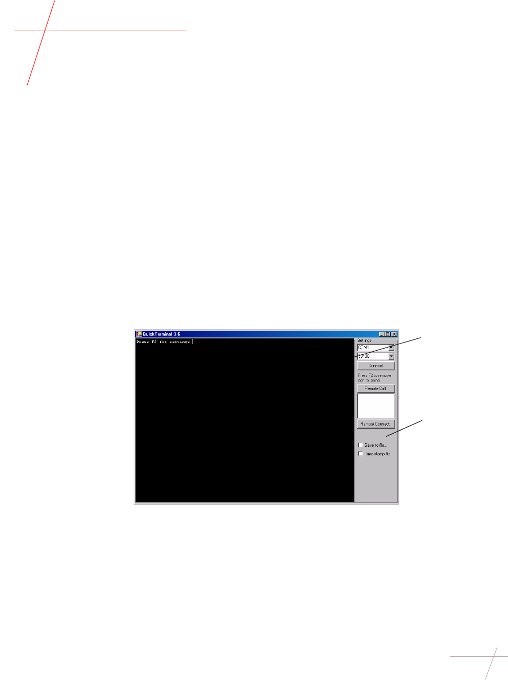
QuickTerminal QuickTerminal displays three windows: the Data window, the Control Panel,
and the Remote Unit Connection window. The Remote Unit Connection window
appears following a successful connection with a repeater.
Data
window
Control
Panel
DRAFT
16 Fixed Network Repeater Installation Guide
TDC-0613-000 10/04
Installing QuickTerminal
Installing QuickTerminal
Overview QuickTerminal may be installed directly on your machine or run directly from
the CD. Note that running QuickTerminal from the CD will result in some per-
formance and speed loss.
Requirements The following software and hardware requirements must be met to run Quick-
Terminal.
Installing
QuickTerminal Itron recommends installing QuickTerminal directly on your configuration
machine. To install QuickTerminal, do the following steps.
Requirement Description
Microsoft Windows Windows XP, 2000, 98, ME, or NT Service
Pack 6a
Microsoft .NET Framework Version 1.1. Available as part of Windows XP
and 2000, or available from Microsoft.
http://windowsupdate.microsoft.com
Serial Port Available serial port capable of communi-
cating at 38400 baud rate
Serial Port Adapter Optional
If your computer does not have a serial port,
you may need to use a USB serial port adapter.
Power Adapter Optional
A power adapter for the 5 volt power cord is
required to operate the programmer in a
vehicle.
Step Action
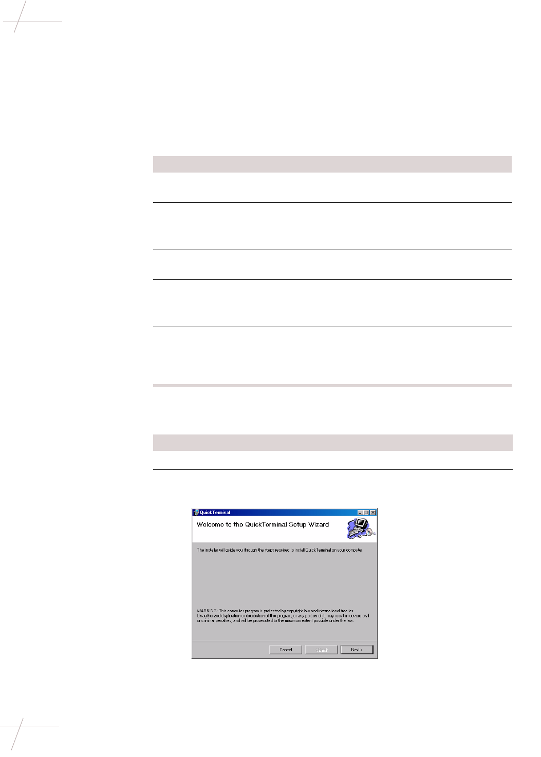
1Insert the QuickTerminal CD.
2Navigate to the Install folder and double-click setup.exe.
The QuickTerminal setup wizard launches.
DRAFT
Chapter 3 - Repeater Configuration 17
TDC-0613-000 10/04
Installing QuickTerminal
Running
QuickTerminal from
CD
To run QuickTerminal directly from the CD, do this.
• Insert the QuickTerminal CD.
• Navigate to the Run folder and double-click QuickTerminal.exe.
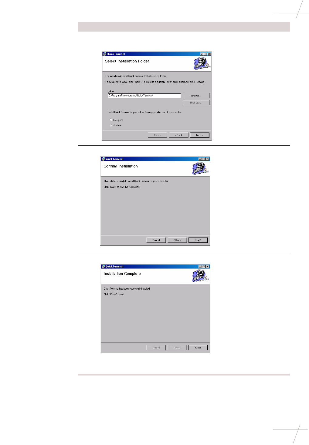
3Click Next to accept the default installation path or browse for an
alternate path.
4Click Next to confirm installation. QuickTerminal installs.
5Click Close.
The QuickTerminal icon will appear on your desktop and in the Start
menu.
Step Action

DRAFT
18 Fixed Network Repeater Installation Guide
TDC-0613-000 10/04
Communicating with a Repeater
Launching
QuickTerminal To launch the QuickTerminal application, do this.
• Double-click the QuickTerminal icon on your desktop or select Start >
QuickTerminal.
Communicating with a Repeater
Setting
Communication
Options
You may need to adjust the COM port or baud rate settings for communicating
with the repeater. To set communication options, do the following steps.
Connecting to a
Remote Repeater An All Call (ACALL) command causes all of the repeaters in communication
distance to move to a single frequency. You must perform a remote call prior to
communicating with a repeater. To connect to a remote repeater, do the fol-
lowing steps.
Step Action
1Connect the programmer to your computer using the serial cable.
2Launch QuickTerminal.
3Press F2.
NOTE To view or minimize the Control Panel, press F2. To enter
command mode, press ESC three times.
4From Settings, select a COM port. The default is COM port 1.
5Select a baud rate setting. The default baud rate is 38400.
6Click Connect.
• If the COM port is available, the message COM1 opened OK
appears. As the programmer begins to read ERT endpoints and
repeaters, data will appear.
• If the COM port is available but the repeater is not connected, the
port will open but no data will appear.
• If the COM port is not available or not present on the machine, an
error message appears.
NOTE Data may not immediately display if the programmer is not
able to read nearby endpoints or repeaters. If no data displays, check
that the repeater is connected by removing and re-inserting the power
cord into the repeaters. A status message should appear.
Step Action
1From the Control Panel, click Remote Call. The remote call processes
and available repeaters display.
2In the data window, enter the password.
3Press Enter to accept the command channel frequency.
NOTE If your utility has opted to use a frequency other than the standard
frequency of 9100, enter your frequency.