Ixia EE11ABG 802.11 a/b/g Emulation Engine User Manual EmulationEngine 11a b g User s Guide
Ixia 802.11 a/b/g Emulation Engine EmulationEngine 11a b g User s Guide
Ixia >
Contents
- 1. User Manual 1 of 3
- 2. User Manual 2 of 3
- 3. User Manual 3 of 3
User Manual 3 of 3

EmulationEngine 11a/b/g User's Guide
Rev #/Date: 2.0.0 Beta/07.17.03 7-1
CHAPTER 7: Event Logging
Overview
During normal operation, the EmulationEngine processes and can
log various types of events. When an event is logged, a record of
the event is stored for future analysis. The event record includes a
timestamp, an indicator of the type of event that occurred, and a
limited amount of data to describe the event.
Event logging is controlled on three levels:
1) master enable (controlled by set evlog enable/disable)
2) verbosity level (controlled by set evlog level <level>)
3) module enable (controlled by set evlog module <module name>
enable/disable)
1) The master enable controls whether event logging occurs at all.
The master control is independent of other filters. If "set evlog
disable" is used, enabling event logging for a particular module
has no effect.
2) The verbosity level sets an “importance” threshold for events: at
lower verbosity, only more “important” events are logged; at higher
verbosity, less important events may also be logged.
3) Each event is processed by a given module or process within
the EmulationEngine. The various processes of the system can be
individually enabled for event logging.
The event logging function stores event records into a buffer area
in memory. The log buffer is a circular buffer that can hold 512
event records. The "get evlog buffer" command can be used to
display the contents of the buffer at any time.
Event data can also be written to a log file in Flash. When writing
to a file is enabled by the "set evlog file enable" command, the log
buffer is flushed to a file every 30 seconds or every time it wraps
at the 512-record limit (which ever comes first). There are two log
files, A and B. The EmulationEngine will alternate between the two
files so that at least one full file is available at any given time.
Each log file can store up to 4,000 event records. You can display
the records stored in either file using the "get evlog file A" and "get
evlog file B" CLI commands.
Event Record Format
Event records are printed in the following format:
[header]: [message] [optional parameters]
Example:
12/27/2002,9:59:57,2296.320226,11396: RX: ok pDesc 0x9326c0
hwStatus 01cd803c:0be20203 numRxDesc 9643712

Communication Machinery Corporation (CMC)
7-2 Rev #/Date: 2.0.0 Beta/07.17.03
where:
[header] is a standard header consisting of a timestamp,
microsecond clock reference and sequence number (e.g.:
12/27/2002,9:59:57,2296.320226,11396)
timestamp = 12/27/2002,9:59:57 (time the event occurred, taken
from the system clock)
microsecond clock reference = 2296.320226 (in seconds,
resolution to 1 microsecond, not sync’ed to timestamp)
sequence number = a sequential number assigned to each record
(e.g., 11396; next event would be 11397, 11398, etc.)
[message] is very brief text string (typically < 15-20 characters)
indicating the type of event that occurred (e.g.: RX: ok indicates a
valid 802.11 frame received without error).
[optional parameters] describe the specific circumstances of this
particular occurrence of the event. It can be up to four 32-bit
parameters. Example: pDesc 0x9326c0 hwStatus
01cd803c:0be20203 numRxDesc 9643712.
CLI Commands
The following CLI commands control event logging:
set evlog enable/disable: This is the master control to enable or
disable event logging (i.e., to the event log buffer in RAM). The
default is enabled.
set evlog level <level>: This command sets the verbosity level
(0/critical, 1/low, 2/medium, or 3/high) for event logging. The
default is critical.
set evlog module <module> enable/disable: This command
enables or disables logging events from the specified module or
process: EmulationEngine control events, virtual station control
events, WLAN transmit and receive events, and User Interface
events. By default, the following processes are enabled for event
logging: EmulationEngine control events and virtual station
control events. The following processes are disabled for event
logging: WLAN transmit and receive events and User Interface
events.
set evlog console enable/disable: This command enables or
disables logging directly to the console. The default is disabled.
set evlog file enable/disable: This command enables or disables
recording logged events to file. The default is disabled.
get evlog settings: This command shows the current event log
control settings.

EmulationEngine 11a/b/g User's Guide
Rev #/Date: 2.0.0 Beta/07.17.03 7-3
get evlog buffer [n] – This command prints the last n events logged
to the log buffer in memory. If [n] is omitted or zero, all events
currently in the log buffer will be displayed.
get evlog file A/B <startRec#> <count>: This command prints
event records in log file A or B. If no starting record number
<startRec#> is given, records are displayed starting with the first
record in the file. If no count of records is given, all records are
displayed. You can also use "?" to display the number of records in
the file.
clear evlog file A/B: This command clears all event records from
log file A or B
clear evlog buffer: This command clears all event records from the
log buffer.
save evlog: This command flushes all records from the log buffer to
the log file, even if log to file is not enabled.
NOTE: Event log control settings are not permanent. They are not
saved with other configuration controls. They must be entered
following startup as desired to change event log operation from the
default settings indicated above.
The Web-Based User Interface
You can configure and display the event log by selecting the
Logging tab in the web-based user interface side bar. See the
"Event Log Side Bar" in Chapter 5 for details.

Communication Machinery Corporation (CMC)
7-4 Rev #/Date: 2.0.0 Beta/07.17.03

EmulationEngine 11a/b/g User's Guide
Rev #/Date: 2.0.0 Beta/07.17.03 8-1
CHAPTER 8: Statistics Counters
The statistics counters defined in this chapter can be:
1) Selected when creating a new monitor in the Monitoring/New
Monitor dialog.
2) Displayed as legends or table headings in a monitor or reports
page.
3) Displayed using CLI commands.
Individual Virtual Station Counters
If statistics for individual virtual stations are selected, one or more
of the following values may be shown.
Individual Virtual Station 802.11 Management Counters
Counter Description
Authentications Number of times the virtual station has Authenticated with
the System Under Test
Deauthentications Number of times the virtual station has Deauthenticated
from the System Under Test
Associations Number of times the virtual station has Associated with the
System Under Test
Disassociations Number of times the virtual station has Disassociated from
the System Under Test
Individual Virtual Station Signal Quality Indication
Counter Description
Rcv Signal
Strength
Signal strength indication for the most recently received
frame
Ack Signal
Strength
Received signal strength indication (RSSI) in the most
recently received ACK frame
Rcv Rate Data rate for the most recently received frame
Tx SF Rate Data rate for the most recently transmitted short frame
Tx LF Rate Data rate for the most recently transmitted long frame
Individual Virtual Station Frame Counts
Counter Description
Rcv MSDUs Total frames received by the virtual station, all frame types
Rcv Data Data frames received by the virtual station
Rcv Mcast Multicast frames received by the virtual station
Rcv Mgmt Management frames received by the virtual station
Rcv Ctrl Control frames received by the virtual station
Tx MSDUs Total frames transmitted by the virtual station, all frame types
Tx Data Data frames transmitted by the virtual station

Communication Machinery Corporation (CMC)
8-2 Rev #/Date: 2.0.0 Beta/07.17.03
Counter Description
Tx Mcast Multicast frames transmitted by the virtual station
Tx Mgmt Management frames transmitted by the virtual station
Tx Ctrl Control frames transmitted by the virtual station
Individual Virtual Station Ping Statistics
These counters are only shown if the virtual station was
configured for internal mode:
Counter Description
Transmit Count Number of Pings the virtual station is configured to send
Transmit Data
Size
Size of the data payload in the ICMP Echo message
Packets
Transmitted
Number of ICMP Echo packets that have been transmitted
Bytes Transmitted Number of data bytes that have been transmitted in ICMP
Echo packets
Transmit
ENOBUFS
Number of times a buffer was not available for transmission
Packets Received Number of ICMP Echo Response packets that have been
received
Bytes Received Number of data bytes that have been received in ICMP Echo
Response packets
Round-trip Min Time difference between transmitted ICMP Echo and
received ICMP Echo Response, minimum observed
Round-trip Max Time difference between transmitted ICMP Echo and
received ICMP Echo Response, maximum observed
Round-trip Avg Average time difference between transmitted ICMP Echo
and received ICMP Echo Response, in microseconds
Round-trip Stddev Standard deviation in time difference between transmitted
ICMP Echo and received ICMP Echo Response
Individual Virtual Station Error Statistics
Counter Description
Rcv Errors Total receive errors
Rcv PHY Errors Receive errors at the PHY level
Rcv CRC Errors CRC errors in received frames
Rcv Duplicates Duplicate frames received
Rcv Discarded Received frames discarded
Ack Rcv Fails ACK receipt failures
Tx Errors Total transmit errors
Excess Retries Transmit retry attempts exceeded
Total Retries Total transmission retries

EmulationEngine 11a/b/g User's Guide
Rev #/Date: 2.0.0 Beta/07.17.03 8-3
Counter Description
Tx Filtered Transmit frames filtered
Tx Discarded Transmit frames discarded
RTS Fails RTS-CTS failures
Authentication Type Virtual station authentication type (open-system or
shared-key)
Encryption Virtual station encryption mode (on/off)
Rcv Decrypt Errs Received frame decryption CRC errors
FCS_Fails Frame checksum errors in received frames
WEP_Excluded Received frames that were rejected because of incorrect
encryption
Summary Statistics
Summary statistics provide a summary report taken over a set of
virtual stations. The virtual station set can be a defined group or
all virtual stations currently in the system. In contrast, the
individual virtual station statistics report provides a list of
statistics and counters for an individual virtual station. The
summary report provides a summary of the statistics and
counters taken over the indicated set of virtual stations. The
summary gives, for each counter, the minimum and maximum
values for that counter found in the set of virtual stations
examined, the average value, and where applicable the total (sum)
over the set of virtual stations. If summary statistics are selected,
one or more of the following values may be shown.
Summary Signal Counters
Counter Description
RxSigMin Minimum signal strength indication for received frames
RxSigMax Maximum signal strength indication for received frames
RxSigAvg Average signal strength indication for received frames
AckSigMin Minimum received signal strength indication (RSSI) in received
ACK frames
AckSigMax Maximum received signal strength indication (RSSI) in received
ACK frames
AckSigAvg Average received signal strength indication (RSSI) in received
ACK frames
RxRateMin Minimum data rate for received frames
RxRateMax Maximum data rate for received frames
RxRateAvg Average data rate for received frames
TxRateSfMin Minimum data rate for transmitted short frames
TxRateSfMax Maximum data rate for transmitted short frames
TxRateSfAvg Average data rate for transmitted short frames

Communication Machinery Corporation (CMC)
8-4 Rev #/Date: 2.0.0 Beta/07.17.03
Counter Description
TxRateLfMin Minimum data rate for transmitted long frames
TxRateLfMax Maximum data rate for transmitted long frames
TxRateLfAvg Average data rate for transmitted long frames
Summary Transmit Statistics
Counter Description
TxMsduMin Minimum frames transmitted per virtual station, all frame
types
TxMsduMax Maximum frames transmitted per virtual station, all frame
types
TxMsduAvg Average frames transmitted per virtual station, all frame types
TxMSDUs Total frames transmitted by all virtual stations, all frame types
TxDataMin Minimum data frames transmitted per virtual station
TxDataMax Maximum data frames transmitted per virtual station
TxDataAvg Average data frames transmitted per virtual station
TxDataFrames Total data frames transmitted by all virtual station
TxMcastMin Minimum Multicast frames transmitted per virtual station
TxMcastMax Maximum Multicast frames transmitted per virtual station
TxMcastAvg Average Multicast frames transmitted per virtual station
TxMcastFrames Total Multicast Frames transmitted by all virtual stations
TxMgmtMin Minimum Management Frames transmitted per virtual station
TxMgmtMax Maximum Management Frames transmitted per virtual station
TxMgmtAvg Average Management Frames transmitted per virtual station
TxMgmtFrames Total Management Frames transmitted by all virtual stations
TxCtrlMin Minimum Control Frames transmitted per virtual station
TxCtrlMax Maximum Control Frames transmitted per virtual station
TxCtrlAvg Average Control Frames transmitted per virtual station
TxCtrlFrames Total Control Frames transmitted by all virtual stations
TxRetryMin Minimum transmission retries per virtual station
TxRetryMax Maximum transmission retries per virtual station
TxRetryAvg Average transmission retries per virtual station
TxTotalRetries Total transmission retries by all virtual stations
TxErrMin Minimum transmission errors per virtual station
TxErrMax Maximum transmission errors per virtual station
TxErrAvg Average transmission errors per virtual station
TxErrors Total transmission errors by all virtual stations
Summary Receive Statistics
Counter Description

EmulationEngine 11a/b/g User's Guide
Rev #/Date: 2.0.0 Beta/07.17.03 8-5
Counter Description
RxMsduMin Minimum frames received per virtual station, all frame types
RxMsduMax Maximum frames received per virtual station, all frame types
RxMsduAvg Average frames received per virtual station, all frame types
RxMSDUs Total frames received by all virtual stations, all frame types
RxDataMin Minimum data frames received per virtual station
RxDataMax Maximum data frames received per virtual station
RxDataAvg Average data frames received per virtual station
RxDataFrames Total data frames received by all virtual stations
RxMcastMin Minimum Multicast frames received per virtual station
RxMcastMax Maximum Multicast frames received per virtual station
RxMcastAvg Average Multicast frames received per virtual station
RxMcastFrames Total Multicast Frames received by all virtual stations
RxMgmtMin Minimum Management Frames received per virtual station
RxMgmtMax Maximum Management Frames received per virtual station
RxMgmtAvg Average Management Frames received per virtual station
RxMgmtFrames Total Management Frames received by all virtual stations
RxCtrlMin Minimum Control Frames received per virtual station
RxCtrlMax Maximum Control Frames received per virtual station
RxCtrlAvg Average Control Frames received per virtual station
RxCtrlFrames Total Control Frames received by all virtual stations
RxErrMin Minimum receive errors per virtual station
RxErrMax Maximum receive errors per virtual station
RxErrAvg Average receive errors per virtual station
RxErrors Total receive errors by all virtual stations
Summary Error Statistics
Counter Description
Rcv_PHY_Errors Receive errors at the PHY level
Rcv_CRC_Errors CRC errors in received frames
Rcv_Discarded Total received frames discarded
Rcv_Duplicates Duplicate frames received
Ack_Rcv_Fails ACK receipt failures
FCS_Fails Frame checksum errors in received frames
Tx_Discarded Total transmit frames discarded
Tx_Excess_Retries Transmit retry attempts exceeded
Rcv_Decrypt_Errors Received frame decryption CRC errors
WEP_Excluded Received frames rejected because of incorrect encryption

Communication Machinery Corporation (CMC)
8-6 Rev #/Date: 2.0.0 Beta/07.17.03

EmulationEngine 11a/b/g User's Guide
Rev #/Date: 2.0.0 Beta/07.17.03 9-1
CHAPTER 9: Troubleshooting
Login Name and/or Password Recovery
If configuration records for your EmulationEngine are lost and you
do not remember its user name or password, it may not be
possible to log in to the device. If this should happen, a special
login sequence will direct the EmulationEngine to reset the login
name and password to their factory defaults.
Open a telnet connection to the device
At the login prompt, type RESET in response to the EE login
prompt and FACTORY in response to the Password prompt. These
are both case sensitive. Example:
EE login: RESET
Password: *******
In response to this sequence, the EmulationEngine will reset both
the login username and the login password to their factory
defaults (User Name: Admin, Password: EE). A new configuration
file with the reset login and password will be written to the Flash
file system, and the EmulationEngine will issue a new login
prompt. No other configuration parameters are affected by this
operation.
You may now log in using the factory default login name (Admin)
and password (EE). Following successful login, you may use the
"set login" or "set password" CLI commands to set these
parameters as desired. Be sure to record the new settings for
future reference.
Using a Third-Party Load Generator
Symptom: Telnet or the Web Client becomes unresponsive during
a test or cannot connect at the conclusion of a test.
Possible Problems:
If your Load Generator exceeds the maximum 802.3 rate specified
in the EmulationEngine Specifications during a test: 1) Telnet
and/or the Web Client may not be able to establish a new
connection. 2) If connected, Telnet and/or the Web Client may lose
connectivity to the EmulationEngine.
If Telnet or the Web Client become unresponsive during a test or
cannot connect at the conclusion of a test, make sure your Load
Generator is not responding to ARP requests that are targeted to
the EmulationEngine address. If this occurs, the ARP request
transmitted from the PC Client (running telnet) or the Web Client
for the purpose of obtaining the MAC address of an IP address,
will respond with the Load Generator's MAC address instead of the
EmulationEngine's MAC address. All data sourced from the PC

Communication Machinery Corporation (CMC)
9-2 Rev #/Date: 2.0.0 Beta/07.17.03
client would incorrectly be destined to the Load Generator instead
of the EmulationEngine.
Web-Based User Interface Login Error
If you are running a personal firewall product (e.g., ZoneAlarm,
McAfee's software firewall, etc.) on the command PC, the following
error dialog may be displayed by your browser immediately
following successful log-in to the EmulationEngine web server:
If this error dialog is displayed, just click the No button to
continue. This error has not impact on the operation of the web-
based user interface or the EmulationEngine.
Hardware Installation/LEDs
Power LED: When you apply power to the EmulationEngine, the
power LED (the left-most LED facing the front of the unit) should
flash momentarily and then light ON (solid). If this does not occur,
check the power cable connection and/or the power outlet where
the power supply is installed. If power is being supplied to the unit
and the Power LED remains off, it may indicate that the
EmulationEngine’s software image file (EE22.SYS) cannot be
loaded into flash (i.e., corrupted or does not exist).
Ethernet LED: When you attach the Ethernet cable between the
command PC and the EmulationEngine, the Ethernet link LED
(the middle LED) should flash momentarily and then light ON
(solid). This should occur if you are attaching directly to the
EmulationEngine using a cross-over cable or through a
hub/switch using a straight cable. If the LED remains OFF, check
the cable connections. If the LED remains OFF, one or more of the
following problems may exist:
Incorrect or defective cable
Defective hub/switch
Using the wrong port on a hub/switch (i.e., uplink port instead of
10/100 port)
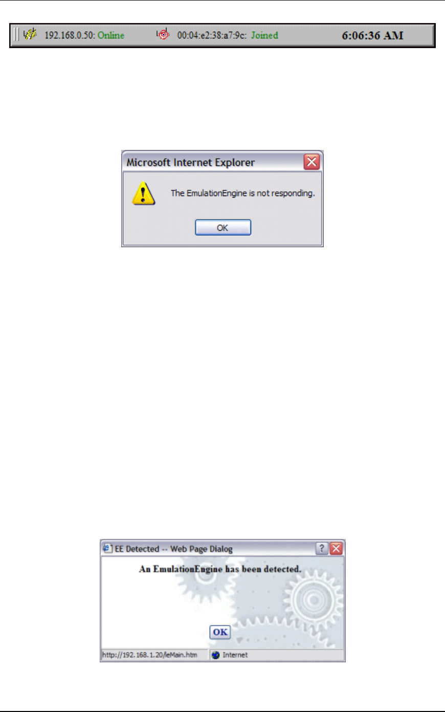
EmulationEngine Busy or Not Responding
The status bar in the top-right corner of the web-based user
interface main page shows the status of the EmulationEngine with
the System Under Test.
EmulationEngine 11a/b/g User's Guide
Rev #/Date: 2.0.0 Beta/07.17.03 9-3
The status (e.g., Online) next to the EmulationEngine IP address
indicates the current status of EmulationEngine with with the
web-based user interface. This status may intermittently display
“Busy”. If the Busy condition lasts longer than the Polling Timeout
specified in the Configure EmulationEngine dialog, the status will
change to Not Responding and the following dialog will be
displayed:
When this dialog is displayed, the user interface will disable all
actions until the EmulationEngine starts responding again. When
you click “OK” to dismiss this dialog, the
EmulationEngine/System connection status in the status bar will
display “Offline”.
If Busy is frequently shown in the status bar, increase the value of
the Polling Interval in the Configure EmulationEngine dialog (see
EE->Configure EE).
If the “EmulationEngine Not Responding” dialog is displayed
frequently, increase the value of the EE Polling Timeout in the
Configure EmulationEngine dialog (see EE->Configure EE).
If the “EmulationEngine Not Responding” dialog continues to be
displayed, check the cable connections between the command PC
and the EmulationEngine.
You may also establish a telnet connection to access and log in to
the CLI to verify that the EmulationEngine is or is not responding.
When Not Responding status is cleared and the web-based user
interface receives a response from the EmulationEngine, the
following dialog will be displayed:

Communication Machinery Corporation (CMC)
9-4 Rev #/Date: 2.0.0 Beta/07.17.03
Loading Files from the Command PC
If you attempt to load a scenario file from the command PC using
the web-based user interface, the browser may display the
following warning dialog:
Click “OK” to continue.
Missing Key File
The EmulationEngine is offered in four configurations:
EmulationEngine 11a: Supports IEEE 802.11a only.
EmulationEngine 11b: Supports IEEE 802.11b only.
EmulationEngine 11a/11b: Supports IEEE 802.11a and 802.11b.
EmulationEngine 11a/b/g: Supports IEEE 802.11a, 802.11b, and
802.11g.
Each configuration is shipped with a unique feature key that is
stored in the EmulationEngine’s flash file system. If the keyfile
does not exist or is corrupted or you have requested a feature
upgrade, the CLI will prompt you to enter your authorization code
in order to create the keyfile. There are only two conditions where
the authorization code must be entered.
1) Feature Upgrades
2) Corrupted or non-existent keyfile
NOTE: The web-based user interface does not provide any
indication of a missing keyfile. When the keyfile is missing, the
EmulationEngine’s web server will not respond to the browser.
If the keyfile has been corrupted or does not exist or you have
requested a feature upgrade, you will be prompted to enter your
unique key/authorization code when you establish a telnet or
serial connection and log in to the CLI.
Example:
telnet 192.168.0.50
EE login: Admin
Password: **

EmulationEngine 11a/b/g User's Guide
Rev #/Date: 2.0.0 Beta/07.17.03 9-5
Communication Machinery Corporation
EmulationEngine(tm) 11a/b/g Rev 2.0.0
System date & time is THU JAN 01 00:00:44 1970
Use the "set date" or "set time" command to adjust
EmulationEngine 11a/b/g software version 2.0.0
WLAN mode .................... 802.11a
WLAN MAC address ............. 00:0b:cd:59:23:57
WLAN address mask ............ ff:ff:ff:ff:00:00
LAN MAC address .............. 00:0b:16:00:00:07
BSSID of System Under Test.... 00:60:1d:f0:de:97
The EmulationEngine is not joined with the SUT.
0 vSTAs currently in the system.
*** This EmulationEngine has not been Node Locked
*** Please enter "admin" to continue
Enter the “admin” command and enter “cmc” at the password
prompt:
CMC_EE -> admin
Password: ***
Ok
When administrative mode is activated with this command, the
CLI will prompt for the authorization code:
Please Enter EE Authorization Codes for MAC:
00:0b:16:00:00:07
CMC_EE ->
Enter your authorization code at the CMC_EE-> prompt. This
authorization code is provided on a separate sheet in your
shipping container with the EmulationEngine. If you have lost
your authorization code, please contact CMC Technical Support
(www.cmc.com).
After you enter the correct authorization code, the CLI will display
the following message.
Thank you...Authorization Codes Accepted
When this message is displayed, the keyfile is created in flash and
this procedure will no longer be required.

Communication Machinery Corporation (CMC)
9-6 Rev #/Date: 2.0.0 Beta/07.17.03
Configuration Records
Print this page and use the following form to keep a record of
EmulationEngine configuration parameters:
Parameter Default CLI Command Configured Value
IP address 192.168.0.50 set ipaddr
Subnet mask 255.255.255.0 set ipmask
Gateway 192.168.1.254 set gateway
Username Admin set login
Password EE set password
WLAN Base
MAC Address
set eemac
WLAN MAC
Mask
ff:ff:ff:ff:00:00 set eemask

EmulationEngine 11a/b/g User's Guide
Rev #/Date: 2.0.0 Beta/07.17.03 A-1
APPENDIX A: Specifications
Hardware
Standards: IEEE 802.11a, IEEE 802.3 and IEEE 802.3u, IEEE 802.1d, IEEE
802.11a, IEEE 802.11b, IEEE 802.11g
Ports:
(1) 10/100Base-T Ethernet, RJ-45(UTP)
(1) RS-232 (DB9)
(1) Power - 5V DC, 2.5A
Frequency Range: 802.11a: 5GHz Unlicensed National Information
Infrastructure (UNII) band, 802.11b/g: 2.4 GHz band.
Modulation Technology: Orthogonal Division Frequency Multiplexing (OFDM)
and Complementary Code Keying (CCK)
Modulation Techniques:
Receiver Sensitivity:
54, 48, 36, 24, 18, 9, 6 Mbps OFDM
11, 5.5 Mbps CCK
2 Mbps QPSK (Quadrature Phase Shift Keying)
1 Mbps BPSK (Binary Phase Shift Keying)
Media Access Control: CSMA/CA
Wireless Frequency Range:
2.4 to 2.4825 MHz
5.150 to 5.850 GHz
LEDs:
Power
Ethernet Link/Activity
Wireless Activity
Antenna Type: Tri-mode dual 5dBi dipole antennas with diversity, Power
software configurable.
Physical Dimensions:
L = 9.25 inches
W= 6.38 inches
H = 1.63 inches
Temperature
Operating: 0°C to 55°C (32°F to 131°F)
Storing: -20°C to 65°C (-4°F to 149°F)
Humidity: 5%-95%, non-condensing
Safety and Emissions: FCC

Communication Machinery Corporation (CMC)
A-2 Rev #/Date: 2.0.0 Beta/07.17.03
Software
EmulationEngine Core:
IEEE 802.11a, 802.11b, 802.11g
Maximum number of virtual stations: 64
Performance: See the EmulationEngine Specifications sheet for detailed
performance figures.
Network Management: Web-Based browser with JavaScript and Command
Line Interface (CLI)
Web-Based User Interface:
Maximum number of groups per Scenario: 10
Maximum monitors per Scenario: 4
Encryption:
Cipher Encryption Mode: Shared WEP key on per virtual station basis
Authentication: Open-system and shared keys on per virtual station basis
Shared keys: up to 4 keys
Shared WEP encryption keys: 64-, 128-, 152-bit
RTS/CTS: Support for RTS/CTS
Fragmentation: Fragment Threshold support
Rates: 802.11a: 6, 9, 12, 18, 24, 26, 48, 54 Mbps. 802.11b: 1, 2, 5.5, 11 Mbps.
802.11g: 1, 2, 5.5, 11, 6, 9, 12, 18, 24, 36, 48, 54.
Circular Event Log: up to 8000 records
Telnet Sessions: up to 4
Maximum 802.3 packet size: 1518 bytes
802.11 Emulation: Fully emulates 802.11 station states in terms of:
authentication, association, disassociation, de-authentication
Operational Mode: Constant Awake Mode (CAM)
External mode: IP traffic only
Channels supported in GHz: 802.11a: 36(5.180), 40(5.200), 44(5.220),
48(5.240), 52(5.260), 56(5.280), 60(5.300), 64 (5.320), 149 (5.745), 153
(5.765), 157 (5.785), 161 (5.805), 165 (5.825). 802.11b/g: 1 (2.412), 2 (2.417),
3 (2.422), 4 (2.427), 5 (2.432), 6 (2.437), 7 (2.442), 8 (2.447), 9 (2.452), 10
(2.457), 11 (2.462).
Internal Log-In: user name and password
Flash size: 3.0 MBytes Total/1.2 MBytes Available for storing scenarios, event
logs and statistics

EmulationEngine 11a/b/g User's Guide
Rev #/Date: 2.0.0 Beta/07.17.03 B-1
APPENDIX B: Software Upgrades
Complete the following steps to load a new software file into the
EmulationEngine’s flash file system:
1) If you are already logged in to the CLI, type reboot to return the
EmulationEngine to a known state:
reboot
2) Use Telnet to log back in to the CLI:
telnet 192.168.0.50
EE login: Admin
Password: EE
EmulationEngine Rev x.x
CMC_EE ->
This step uses the EmulationEngine’s default IP address
(192.168.0.50). If you have changed the IP address, use the
address you previously configured in the EmulationEngine.
3) Use the "ls" command to verify that there is enough space in
the flash file system for the new software.
CMC_EE -> ls
4) Compare the bytes free count to the size of the software file you
want to download. If there is not enough space, use the "rm"
command to remove one or more files from flash. DO NOT remove
the keyfile.
CMC_EE -> rm <file_name>
5) You must have an FTP server running in order to complete this
step. In the CLI, enter the "ftp" command and the command PC’s
IP address. Example:
CMC_EE -> ftp 192.168.0.2
6) Enter your FTP server user name and password. Just press
<Return> in response to either prompt if there is no user name or
password.
Username: <your_user_name>
Password: <your_password>
7) At the prompt for a remote file, give the pathname to the latest
EE22.SYS file on your PC (e.g., c:\EE22.SYS). For the local file
use EE22NEW.SYS. Enter “down” at the “dowload or upload”
prompt.
Remote File: c:\EE22.SYS
Local File: EE22NEW.SYS
download or upload: down
Getting @192.168.0.2:c:\EE22.SYS -> EE22NEW.SYS
###########################################################
###########################################################
###########################################################
###########################################################
###########################################################

Communication Machinery Corporation (CMC)
B-2 Rev #/Date: 2.0.0 Beta/07.17.03
###########################################################
###########################################################
###########################################################
###########################################################
###########################################################
###########################################################
###########################################################
###########################################################
###########################################################
#
done
1007441 bytes
CMC_EE ->
8) When the transfer is complete, use the "ls" command to verify
that the size of the file in Flash is the same number of bytes as the
file on the FTP server/command PC.
CMC_EE -> ls
9) At the CMC_EE-> prompt, type the following command to move
the file and use the correct boot name.
CMC_EE -> mv EE22NEW.SYS EE22.SYS
10) When the move is complete, use the "ls" command to verify the
file has been moved with the correct name.
CMC_EE -> ls
11) Use the "reboot" command to reboot the EmulationEngine and
to activate the new software.
CMC_EE -> reboot
After reboot, you must reestablish the telnet session in order to log
back in to the CLI. If the CLI displays the message “This
EmulationEngine has not been Node Locked” after you enter the
EE login name and password, see “Missing Key File” in Chapter 9.
Troubleshooting.
EmulationEngine 11a/b/g User's Guide
Rev #/Date: 2.0.0 Beta/07.17.03 C-1
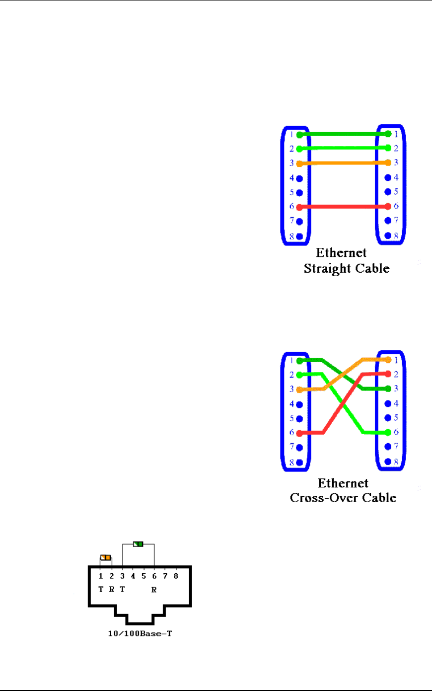
APPENDIX C: Cable Pin Assignments
Standard Ethernet Cable
A straight cable can be used to connect the Command PC to a hub
and the hub to the EmulationEngine For a straight cable; the
wires match one for one. This cable is not provided.
Pin 1: Rx+
Pin 2: Rx-
Pin 3 : Tx+
Pin 4 : Not Used
Pin 5 : Not Used
Pin 6 : Tx-
Pin 7 : Not Used
Pin 8: Not Used
Ethernet Cross-Over Cable
A cross-over cable must be used to connect the Command PC
directly to the EmulationEngine. This cable is provided.
Pin 1: Rx+
Pin 2: Rx-
Pin 3 : Tx+
Pin 4 : Not Used
Pin 5 : Not Used
Pin 6 : Tx-
Pin 7 : Not Used
Pin 8: Not Used
RJ-45 Connector

Communication Machinery Corporation (CMC)
C-2 Rev #/Date: 2.0.0 Beta/07.17.03
Serial Cable
The following table shows the connector pin assignments for the
DB9 connector. The provided serial cable is a straight cable with
female and male connectors. In this table, DTE refers to the
local/EmulationEngine side of the connection and DCE is the
remote side.
DB-9 SIGNAL DIRECTION SIGNAL NAME
1 x Protective Ground
3 DTE-to-DCE Transmitted Data
2 DCE-to-DTE Received Data
7 DTE-to-DCE Request To Send
8 DCE-to-DTE Clear To Send
6 DCE-to-DTE Data Set Ready
5 x Signal Ground
1 DCE-to-DTE Received Line Signal Detector (Carrier Detect)
4 DTE-to-DCE Data Terminal Ready
9 DCE-to-DTE Ring Indicator

EmulationEngine 11a/b/g User's Guide
Rev #/Date: 2.0.0 Beta/07.17.03 D-1
APPENDIX D: Error and Status Messages
The EmulationEngine may display the following error and status
messages in response to incorrect or unexpected user actions or
WLAN activity.
EmulationEngine or Virtual Station Control Messages
Message Description
EE Lost SUT (no
beacons)
The EmulationEngine was joined with the System
Under Test but has stopped receiving beacons from
it.
EE Not joined with
System Under Test
A requested operation could not be performed
because the EmulationEngine is not joined with a
System Under Test.
Internal system error A requested operation resulted in an unspecified
internal error.
Invalid message
identifier
Internal error: the vSTA control task received a
Command message with an invalid message
identifier.
Invalid object identifier The vSTA control task received a GET or SET
Command message with an invalid Object identifier.
Invalid object value The vSTA control task received a SET Command
message with an invalid object value.
Invalid operation Internal error: the vSTA control task received a
Command message with an invalid operation code.
Invalid vSTA identifier The vSTA control task received a Command message
with an invalid vSTA identifier.
Invalid vSTA state for
operation
A requested operation could not be performed
because the specified vSTA is not in the appropriate
state.
vSTA idle A requested operation could not be performed
because the specified vSTA is in the Idle state.
vSTA not configured A requested operation could not be performed
because the specified vSTA has not been Configured.
vSTA not idle A requested operation could not be performed
because the specified vSTA is not in the Idle state.
vSTA not initialized A requested operation could not be performed
because the specified vSTA has not been Initialized.
vStaControl() Err writing
NOTIFY into UI's queue
The vSTA control task cannot post a message
because the UI task’s queue is full. This may occur if
a web user logs out while the EmulationEngine is
running and so may be ignored.
vStaControl() Task for
NOTIFY no longer exists
The vSTA control task cannot post a message
because the UI task is no longer present. This may
occur if a telnet user logs out while the
EmulationEngine is running and so may be ignored.

Communication Machinery Corporation (CMC)
D-2 Rev #/Date: 2.0.0 Beta/07.17.03
MAC Layer Management Messages
Message Description
Invalid parameter Internal error: an MLME function has been invoked
with an invalid parameter.
MLME Already in BSS Internal error: a requested MLME function was
rejected because the EmulationEngine is already a
member of a BSS.
MLME Driver error Internal error: an MLME function has encountered an
unspecified error in the device driver.
MLME Op not supported Internal error: an MLME function has been invoked
which is not supported in the current configuration.
MLME Op refused Internal error: a requested MLME function was
rejected due to other current system activity.
MLME Op timed out An invoked MLME function (e.g., Authentication or
Association) has not completed within programmed
timing parameters.
MLME Too many
requests
Internal error: an MLME function has been invoked
repeatedly without adequate completion.
Standard 802.11 WLAN Reason Codes
Standard 802.11 WLAN Status Codes
Message
Association denied - Reason outside scope of standard
Association denied - STA does not support all data rates
Association denied - too many stations
Authentication frame with unexpected sequence
Authentication rejected - challenge failure
Message Description
Authentication expired The previous authentication of a station is no longer
valid.
Class 2 frame received
STA not AUTH
A class 2 frame was received from a
nonauthenticated station.
Class 3 frame received
STA not ASSOC
A class 3 frame was received from a nonassociated
station.
Inactivity A station was disassociated due to inactivity.
Leaving Station deauthentication or disassociation because
the station is leaving a BSS.
Not authenticated The station requesting association is not
authenticated.
Too many associations The System Under Test is unable to handle all
currently associated stations.
Unspecified Unspecified reason.

EmulationEngine 11a/b/g User's Guide
Rev #/Date: 2.0.0 Beta/07.17.03 D-3
Message
Authentication rejected - next frame timed out
Can't support all requested capabilities
Reassociation denied - Can't confirm association exists
Specified algorithm not supported
Unspecified failure

Communication Machinery Corporation (CMC)
D-4 Rev #/Date: 2.0.0 Beta/07.17.03

EmulationEngine 11a/b/g User's Guide
Rev #/Date: 2.0.0 Beta/07.17.03 Index-1
Index
8
802.11
Association 5-31, 5-65, 5-70, 5-71, 6-10
Authentication 5-31, 5-32, 5-65, 5-69, 5-70, 5-71, 6-10
Deauthentication 5-65, 6-14
Disassociation 5-65, 6-14
Management Counters 8-1
WLAN Reason Codes D-2
WLAN Status Codes D-2
A
Antennas 2-2
Association 5-31, 5-65, 5-70, 5-71, 6-10, 6-31
Authentication 5-31, 5-32, 5-65, 5-69, 5-70, 5-71, 6-10
Authentication Mode 6-16, 6-17, 6-20, 6-24, 6-59
B
Basic Service Set (BSS) ID 6-5
Basic Service Set (BSS) List 6-6
Busy 5-13, 5-39, 9-3
C
Calibration 6-54
Cipher 6-17
Cipher Mode 6-16
CLI
Administrative Mode Commands 6-51
Commands 6-2
Editor 6-63
EmulationEngine Commands 6-31
Event Log Commands 6-26
Log In 9-4
Log Off/Quit 6-2
Statistics Commands 6-25
System Under Test Commands 6-4
Usage Notes 6-1
Virtual Station Set-Up & Control Commands 6-8
CLI Command

Communication Machinery Corporation (CMC)
Index-2 Rev #/Date: 2.0.0 Beta/07.17.03
assoc 6-10
association (get) 6-31
auth 6-10
autoconf 6-11
autorun 6-13
bssid (clear) 6-6
bssid (get) 6-5
bssid (set) 6-5
bsslist (get) 6-6
channel (get) 6-32
conf 6-13
config (get) 6-32
countrycode (get/set) 6-32
date (set) 6-33
deauth 6-14
disassoc 6-14
eestatus (get) 6-35
evlog (save) 6-28
evlog (set) 6-29
evlog buffer (clear) 6-27
evlog buffer (get) 6-27
evlog console (set) 6-29
evlog file (clear) 6-27
evlog file (get) 6-27
evlog file (set) 6-29
evlog level (set) 6-29
evlog module (set) 6-29
evlog settings (get) 6-28
exec 6-35
factorydefault (set) 6-36
frequency (get) 6-37
ftp 6-37
gateway (get/set) 6-38
group (del(ete)) 6-15
group (get) 6-16
group (reset) 6-17
group (set) 6-17
group stats (clear) 6-15
group stats (save) 6-17
group summary (save) 6-17
halt 6-18
hardware (get) 6-38
help 6-39
history 6-39
init 6-19
ipaddr (get/set) 6-39
ipmask (get/set) 6-40
join 6-6
key (del/get/set) 6-40
login (get/set) 6-41
password (set) 6-42

EmulationEngine 11a/b/g User's Guide
Rev #/Date: 2.0.0 Beta/07.17.03 Index-3
ping 6-42
power (get/set) 6-42
quit 6-43
rate (get/set) 6-43
reboot 6-44
retrylimit (get/set) 6-39
rtsthreshold (get/set) 6-44
run 6-19
scan 6-7
sntpserver (get/set/clear) 6-45
statfile group (del(ete)) 6-25
statfile group (get) 6-26
statfile vsta (del(ete)) 6-25
statfile vsta (get) 6-26
station (get) 6-45
summfile group (del(ete)) 6-25
summfile group (get) 6-26
summfile vsta all (del(ete)) 6-26
summfile vsta all (get) 6-26
systemname (clear/get/set) 6-45
telnet (get) 6-46
time (set) 6-46
timeofday 6-46
tzone (get/set) 6-47
uptime (get) 6-47
version (get) 6-47
vsta (del(ete)) 6-20
vsta (get) 6-20
vsta (reset) 6-23
vsta (set) 6-23
vsta all summary (save) 6-23
vsta stats (clear) 6-19
vsta stats (save) 6-23
Command Line Interface (CLI) 6-1
Command PC Setup 4-1
Configuration
Encryption 5-61
Ping Defaults 5-62
Preferences 5-62
Country Code 6-32
D
Data Rate 6-43
Date/Time 6-33, 6-46
Deauthentication 5-65, 6-14
Default Configuration
Encryption 5-61

Communication Machinery Corporation (CMC)
Index-4 Rev #/Date: 2.0.0 Beta/07.17.03
Ping 5-62
Disassociation 5-65, 6-14
E
EmulationEngine
Busy 5-13, 5-39
Changing IP Address 6-59
CLI Commands 6-31
Configuration 5-38, 6-32
IP Address 5-42
IP Mask 6-40
Not Reponding 9-3
Not Responding 5-40
Polling Interval 9-3
Polling Timeout 9-3
Reboot 5-43, 6-44
Receive Parameters 5-39
Reconnect 5-42
Reset 5-43
Status 6-35
Transmit Parameters 5-40
Virtual Station Status 6-45
Encryption
Defaults 5-61
Keys 5-33, 5-61, 6-12, 6-40
Mode 5-32, 6-12, 6-16, 6-17, 6-20, 6-24
Ethernet Compatibility 1-4
Ethernet Connector 2-2
Event Log 5-53, 7-1
Clear 5-54, 6-27
CLI Commands 6-26
Configuration 5-55, 6-28
Controls/Configuration 6-29
Display 5-53, 6-27
Export 5-55
Modules 5-56, 6-29, 7-1, 7-2
Record Format 7-1
Verbosity Level 5-56, 6-29, 7-1, 7-2
External Mode 5-9, 5-27, 6-12, 6-13
F
Factory Default Configuration 6-36
File Transfer Protocol (FTP) 6-37
Files 1-3
Command 6-35

EmulationEngine 11a/b/g User's Guide
Rev #/Date: 2.0.0 Beta/07.17.03 Index-5
Event Log 6-27, 7-1
Statistics 6-25
Summary Statistics 6-26
G
GID 5-17
Group Control 5-16
H
Hardware 6-38
I
Installation 3-1
Internal Mode 5-6, 5-27, 6-12, 6-13
Interval
EmulationEngine Polling 5-40
Monitor Update 5-52
IP Address 6-38, 6-39
Iteration 5-17, 5-28, 5-29, 5-63
L
LEDs 2-1
Ethernet LED Off 2-2
Status at Installation 9-2
Load Profiles 5-19, 5-22
Logging
CLI Commands 6-26
Login 6-1
M
Menus 5-63
Edit 5-69
File 5-67
Group 5-70
Options 5-72
Reports 5-72
Scenario 5-69
vSTA 5-71
Monitor Controls 5-49
Monitors 5-44

Communication Machinery Corporation (CMC)
Index-6 Rev #/Date: 2.0.0 Beta/07.17.03
Clear 5-50
Configure 5-52
Delete 5-49
Export 5-50
Maximum Number 5-45
Predefined 5-45
Stored in RAM 5-45
Summary 5-46
Toolbar 5-65
Update Interval 5-52
Update Timeout 5-52
Virtual Station 5-47
N
Not Responding 9-3
P
Password 6-1, 6-42
Recovery 9-1
Persistence 5-30, 6-24
Ping Configuration 5-62
Polling Interval 5-13, 5-40
Polling Timeout 5-13, 5-40
Power Supply Connector 2-2
Preferences 5-62
R
Radio Channel/Frequency 6-32
Radio Frequency 6-37
Reboot 5-43, 6-44
Reports 5-57
Export 5-60
Group Summary 5-58
Master Station 5-59
Scenario Summary 5-57
Templates 5-60
Virtual Station Detail 5-59
RJ-45 Ethernet Connector 2-2
RTS/CTS Threshold 6-44

EmulationEngine 11a/b/g User's Guide
Rev #/Date: 2.0.0 Beta/07.17.03 Index-7
S
Scenario
Create New 5-3, 5-6
Group 5-24, 5-70
Menu 5-69
Open Existing 5-4
Run 5-10
Save 5-11
Security 5-61
Security Configuration Example 6-58
Side Bar Buttons 5-14
SNTP Server 6-45
Software Upgrades B-1
Statistics
Clear 6-20
CLI Commands 6-25
File 6-26
Group 6-19
Saving 6-17
Signal Counters 8-2
Virtual Stations 6-19, 8-1
Statistics Summary 8-3
Status/Error Messages D-1
System Name 6-45
System Requirements 1-4, 5-1
System Under Test
BSS List 6-5
Changing 6-4
CLI Commands 6-4
Join 5-10, 5-38, 6-6
Scan 5-20, 6-7
Select System Under Test 5-3, 5-36
T
Test Toolbar 5-14, 5-64
Time Zone 6-47
Toolbars 5-63
Traffic Types 5-26
Transmit Power 6-42
Transmit Retries 6-39

Communication Machinery Corporation (CMC)
Index-8 Rev #/Date: 2.0.0 Beta/07.17.03
U
User Interface Configuration 5-62
User Name 6-1, 6-41
V
Virtual Stations 5-24
Add to Group 5-35
Address Generation 5-26
Auto Configure 6-11
CLI Commands 6-8, 6-20
Configure 5-24, 6-13
Edit 5-17
Encryption 5-31, 6-12, 6-20
Halt 5-65, 5-71, 6-18
Initialize 5-65, 5-71, 6-19
IP Addresses 5-26, 6-11, 6-24
Life Cycle 6-9
MAC Addresses 5-26, 6-11, 6-13, 6-24
Persistence 5-30, 5-31
Run 5-65, 5-71, 6-19
Run Time Parameters 5-29
Statistics 6-19
Status 6-45
Toolbar 5-14, 5-65
Traffic Types 5-27, 6-12, 6-13, 6-24
Transitional States 5-63
W
Web-Based User Interface 5-1
Welcome Screen 5-2, 5-63