Ixia EE11ABG 802.11 a/b/g Emulation Engine User Manual EmulationEngine 11a b g User s Guide
Ixia 802.11 a/b/g Emulation Engine EmulationEngine 11a b g User s Guide
Ixia >
Contents
- 1. User Manual 1 of 3
- 2. User Manual 2 of 3
- 3. User Manual 3 of 3
User Manual 1 of 3

Release Date: 07.17.03
Rev 2.0.0 Beta
Communication Machinery Corporation | 402 E. Gutierrez Street | Santa Barbara, CA. 93101
Phone: 1.805.879.1521| Fax: 1.805.564.7188 | Web: www.cmc.com

Communication Machinery Corporation (CMC)
ii Rev #/Date: 2.0.0 Beta/07.17.03
Copyright & Trademark Notices
Copyright 2003 by Communication Machinery Corporation (CMC). All rights
reserved. This document may not be reproduced in whole or in part by any
means without the written consent of CMC.
EmulationEngine and vSTA are registered trademarks of Communication
Machinery Corporation.
The web-based user interface uses the GoAhead WebServer: Copyright (c) 2003
GoAhead Software, Inc. All rights reserved.
Radio Frequency Interference Requirements
802.11a devices transmit in the 5 GHz band. 802.11b and 802.11g devices
transmit in the 2.4 GHz band. FCC regulations require this product to be used
indoors to reduce the potential for interference with (to or from) other devices
that operate in the same frequency range.
FCC Warning
This equipment has been tested and found to comply with the limits for a Class B
digital device, pursuant to Part 15 of the FCC rules. These limits are designed to
provide reasonable protection against harmful interference in a residential
installation. This equipment generates, uses, and can radiate radio frequency
energy and, if not installed and used in accordance with the instructions, may
cause harmful interference to radio communications. There is no guarantee that
interference will not occur in a particular installation. If this equipment does
cause harmful interference to radio or television reception, which can be
determined by turning the equipment off and on, the user is encouraged to try to
correct the interference by one or more of the following measures:
Reorient or relocate the radio /TV receiving antenna.
Increase the separation between the equipment and the radio/TV receiver.
Connect the equipment to an outlet that is on a different circuit from where the
radio/TV receiver is connected.
Consult the dealer or an experienced radio/TV technician for help.
Unless expressly approved by CMC, modifications to this product could void the
user's authority to operate the equipment.
RF Exposure Requirements
To ensure compliance with FCC RF exposure requirements, the antenna used for
this device must be installed to provide a separation distance of at least 20 cm
from all persons and must not be co-located or operating in conjunction with any
other antenna or radio transmitter. Installers and end-users must follow the
installation instructions provided in this guide.

EmulationEngine 11a/b/g User's Guide
Rev #/Date: 2.0.0 Beta/07.17.03 iii
TABLE OF CONTENTS
CHAPTER 1: Overview ..........................................................................................1-1
Packaging Checklist ..................................................................................1-2
Feature List...............................................................................................1-2
Files ..........................................................................................................1-3
System Requirements ................................................................................1-4
Hardware Characteristics ..........................................................................1-4
General Usage Notes..................................................................................1-4
CHAPTER 2: Connectors, LEDs & Antennas ......................................................2-1
Front Panel/LEDs .....................................................................................2-1
Back Panel ................................................................................................2-2
Connectors............................................................................................. 2-2
Antennas ............................................................................................... 2-2
Reset Button .......................................................................................... 2-2
CHAPTER 3: Installation .......................................................................................3-1
Connecting Directly to a Command PC ......................................................3-1
Connecting Through an Ethernet Hub/Switch ...........................................3-1
Connecting to the Serial Port (Optional) .....................................................3-1
CHAPTER 4: Initial Setup ...................................................................................... 4-1
For an Ethernet Port Connection ...............................................................4-1
For a Serial Port Connection ......................................................................4-3
CHAPTER 5: The Web-Based User Interface ......................................................5-1
System Requirements ................................................................................5-1
Start-Up/Login..........................................................................................5-1
Choosing a Scenario/Test..........................................................................5-2
Create New Scenario .............................................................................. 5-3
Open Existing Scenario .......................................................................... 5-4
The Main Page........................................................................................ 5-5
Creating an Internal Mode/Ping Test ...................................................... 5-6
Creating an External Mode Test.............................................................. 5-9
Running a Test........................................................................................5-10
About/Using the Main Page.....................................................................5-12
Group Control Grid .............................................................................. 5-15
Load Profile.......................................................................................... 5-19
Target Systems..................................................................................... 5-20
Load Profile/Monitor Graphs ................................................................ 5-20
Range Checking/Error Messages .......................................................... 5-21
Using Load Profiles............................................................................... 5-22
vSTA Side Bar .........................................................................................5-23
vSTA->New Group ................................................................................ 5-24
vSTA->New Group->vSTA .................................................................. 5-24
vSTA->New Group->Traffic ................................................................ 5-26
vSTA->New Group->Runtime............................................................. 5-28
vSTA->New Group->On Error ............................................................ 5-30
vSTA->New Group->Encryption ......................................................... 5-31
vSTA->Edit Group ................................................................................ 5-33
vSTA->Delete Group............................................................................. 5-34
vSTA->Add New vSTA to Group ............................................................ 5-34
EE (EmulationEngine) Side Bar ...............................................................5-36

Communication Machinery Corporation (CMC)
iv Rev #/Date: 2.0.0 Beta/07.17.03
EE->Select SUT.................................................................................... 5-36
EE->Join SUT ...................................................................................... 5-38
EE->Configure EE ................................................................................ 5-38
EE->Reconnect EE ............................................................................... 5-42
EE->Reset EE ...................................................................................... 5-43
EE->Reboot EE .................................................................................... 5-43
Monitors Side Bar....................................................................................5-44
Monitors->New Monitor ........................................................................ 5-45
Monitors->New Monitor->Predefined.................................................. 5-45
Monitors->New Monitor->Summary ................................................... 5-46
Monitors->New Monitor->vSTA .......................................................... 5-47
Monitors->Delete Monitor..................................................................... 5-49
Monitors->Clear Monitor ...................................................................... 5-50
Monitors->Export Monitor .................................................................... 5-50
Monitors->Config Monitors ................................................................... 5-52
Event Log Side Bar ..................................................................................5-53
Event Log->Event Log........................................................................... 5-53
Event Log->Clear Log ........................................................................... 5-54
Event Log->Export Log ......................................................................... 5-55
Event Log->Configure Log..................................................................... 5-55
Reports Side Bar ..................................................................................... 5-57
Reports->Scenario Summary ................................................................ 5-57
Reports->Group Summary.................................................................... 5-58
Reports->vSTA Master.......................................................................... 5-59
Reports->vSTA Detail ........................................................................... 5-59
Reports->Export Reports ...................................................................... 5-60
Configuration Side Bar ............................................................................ 5-60
Configuration->Encryption ................................................................... 5-61
Configuration->Ping Defaults ............................................................... 5-61
Configuration->Preferences .................................................................. 5-62
Menus & Toolbars ...................................................................................5-63
File Toolbar.......................................................................................... 5-64
Edit Toolbar ......................................................................................... 5-64
Scenario Toolbar .................................................................................. 5-64
vSTA Toolbar........................................................................................ 5-65
Reports Toolbar.................................................................................... 5-65
Monitor Toolbar ................................................................................... 5-65
File Menu............................................................................................. 5-67
Edit Menu............................................................................................ 5-69
Scenario Menu ..................................................................................... 5-69
Group Menu......................................................................................... 5-70
vSTA Menu .......................................................................................... 5-71
Reports Menu ...................................................................................... 5-72
Options Menu ...................................................................................... 5-72
CHAPTER 6: The Command Line Interface (CLI)................................................ 6-1
CLI Usage Notes ........................................................................................6-1
User Log-In ...............................................................................................6-1
User Log-Off ..............................................................................................6-2
CLI Commands..........................................................................................6-2
System Under Test Commands ..................................................................6-4

EmulationEngine 11a/b/g User's Guide
Rev #/Date: 2.0.0 Beta/07.17.03 v
bssid (get/set/clear) ............................................................................... 6-5
get bssid .............................................................................................6-5
set bssid ............................................................................................. 6-5
clear bssid ..........................................................................................6-6
bsslist (get)............................................................................................. 6-6
join ........................................................................................................ 6-6
scan....................................................................................................... 6-6
wirelessmode (get/set) ............................................................................ 6-8
get wirelessmode ................................................................................. 6-8
set wirelessmode ................................................................................. 6-8
Virtual Station Set-Up & Control Commands .............................................6-8
assoc ................................................................................................... 6-10
auth..................................................................................................... 6-10
autoconf............................................................................................... 6-11
autorun ............................................................................................... 6-13
conf ..................................................................................................... 6-13
deauth ................................................................................................. 6-14
disassoc ............................................................................................... 6-14
group (clear/del/get/reset/save/set) .................................................... 6-15
clear group stats ............................................................................... 6-15
del group .......................................................................................... 6-15
get group .......................................................................................... 6-16
reset group........................................................................................ 6-17
save group stats................................................................................ 6-17
save group summary......................................................................... 6-17
set group .......................................................................................... 6-17
halt...................................................................................................... 6-18
init....................................................................................................... 6-18
run ...................................................................................................... 6-19
vsta (clear/del/get/reset/save/set)....................................................... 6-19
clear vsta stats.................................................................................. 6-19
del vsta ............................................................................................. 6-20
get vsta ............................................................................................. 6-20
reset vsta .......................................................................................... 6-23
save vsta stats .................................................................................. 6-23
save vsta all summary....................................................................... 6-23
set vsta ............................................................................................. 6-23
Statistics File Commands ........................................................................6-25
Delete Statistics File............................................................................. 6-25
del statfile group ............................................................................... 6-25
del statfile vsta.................................................................................. 6-25
del summfile group ........................................................................... 6-25
del summfile vsta all ......................................................................... 6-26
Get/Display Statistics File.................................................................... 6-26
get statfile group ............................................................................... 6-26
get statfile vsta.................................................................................. 6-26
get summfile group ........................................................................... 6-26
get summfile vsta all ......................................................................... 6-26
Event Log Commands..............................................................................6-26
Clear Event Log.................................................................................... 6-27

Communication Machinery Corporation (CMC)
vi Rev #/Date: 2.0.0 Beta/07.17.03
clear evlog buffer............................................................................... 6-27
clear evlog file ................................................................................... 6-27
Get/Display Event Log ......................................................................... 6-27
get evlog buffer.................................................................................. 6-27
get evlog file ...................................................................................... 6-27
get evlog settings............................................................................... 6-28
Save Event Log (save evlog)................................................................... 6-28
Set Event Log Controls ......................................................................... 6-29
set evlog............................................................................................ 6-29
set evlog console ............................................................................... 6-29
set evlog file ...................................................................................... 6-29
set evlog level .................................................................................... 6-29
set evlog module................................................................................ 6-29
EmulationEngine Commands ..................................................................6-30
association (get) ................................................................................... 6-31
channel (get) ........................................................................................ 6-32
config (get) ........................................................................................... 6-32
countrycode (get/set)............................................................................ 6-32
get countrycode................................................................................. 6-32
set countrycode................................................................................. 6-33
date (set) .............................................................................................. 6-33
eemac (get/reset/set) ........................................................................... 6-33
get eemac.......................................................................................... 6-34
reset eemac....................................................................................... 6-34
set eemac.......................................................................................... 6-34
eemask (get/set)................................................................................... 6-34
get eemask........................................................................................ 6-35
set eemask........................................................................................ 6-35
eestatus (get)........................................................................................ 6-35
exec ..................................................................................................... 6-35
factorydefault (set)................................................................................ 6-36
features (get/set).................................................................................. 6-36
get features ....................................................................................... 6-36
set features ....................................................................................... 6-36
fragmentthreshold (get/set) .................................................................. 6-37
get fragmentthreshold ....................................................................... 6-37
set fragmentthreshold ....................................................................... 6-37
frequency (get)...................................................................................... 6-37
ftp........................................................................................................ 6-37
gateway (get/set) .................................................................................. 6-38
get gateway ....................................................................................... 6-38
set gateway ....................................................................................... 6-38
hardware (get) ...................................................................................... 6-38
help ..................................................................................................... 6-39
history ................................................................................................. 6-39
hwtxretries (get/set) ............................................................................. 6-39
get hwtxretries .................................................................................. 6-39
set hwtxretries .................................................................................. 6-39
ipaddr (get/set) .................................................................................... 6-39
get ipaddr ......................................................................................... 6-39

EmulationEngine 11a/b/g User's Guide
Rev #/Date: 2.0.0 Beta/07.17.03 vii
set ipaddr ......................................................................................... 6-40
ipmask (get/set) ................................................................................... 6-40
get ipmask ........................................................................................ 6-40
set ipmask ........................................................................................ 6-40
key (del/get/set)................................................................................... 6-40
del key .............................................................................................. 6-40
get key .............................................................................................. 6-40
set key .............................................................................................. 6-41
keyentrymethod (get/set)...................................................................... 6-41
get keyentrymethod........................................................................... 6-41
set keyentrymethod........................................................................... 6-41
login (get/set)....................................................................................... 6-41
get login ............................................................................................ 6-41
set login ............................................................................................ 6-41
password (set) ...................................................................................... 6-42
ping ..................................................................................................... 6-42
power (get/set) ..................................................................................... 6-42
get power .......................................................................................... 6-42
set power .......................................................................................... 6-43
quit...................................................................................................... 6-43
rate (get/set) ........................................................................................ 6-43
get rate ............................................................................................. 6-43
set rate ............................................................................................. 6-43
reboot .................................................................................................. 6-44
rtsthreshold (get/set)............................................................................ 6-44
get rtsthreshold................................................................................. 6-44
set rtsthreshold................................................................................. 6-44
sntpserver (get/set/clear) ..................................................................... 6-45
clear sntpserver ................................................................................ 6-45
get sntpserver ................................................................................... 6-45
set sntpserver ................................................................................... 6-45
station (get) .......................................................................................... 6-45
systemname (clear/get/set) .................................................................. 6-45
clear systemname ............................................................................. 6-45
get systemname ................................................................................ 6-45
set systemname ................................................................................ 6-46
telnet (get/set)...................................................................................... 6-46
get telnet........................................................................................... 6-46
set telnet........................................................................................... 6-46
time (set).............................................................................................. 6-46
timeofday ............................................................................................. 6-46
tzone (get/set) ...................................................................................... 6-47
get tzone ........................................................................................... 6-47
set tzone ........................................................................................... 6-47
uptime (get).......................................................................................... 6-47
version (get).......................................................................................... 6-47
802.11b/g Commands.............................................................................6-48
basic11b (get/set)................................................................................. 6-48
get basic11b (11b only)...................................................................... 6-48
set basic11b (11b only)...................................................................... 6-48

Communication Machinery Corporation (CMC)
viii Rev #/Date: 2.0.0 Beta/07.17.03
ctsmode (get/set).................................................................................. 6-48
get ctsmode (11g only)....................................................................... 6-49
set ctsmode (11g only)....................................................................... 6-49
ctsrate (get/set).................................................................................... 6-49
get ctsrate (11g only) ......................................................................... 6-49
set ctsrate (11g only) ......................................................................... 6-49
ctstype (get/set) ................................................................................... 6-49
get ctstype (11g only)......................................................................... 6-49
set ctstype (11g only)......................................................................... 6-49
gdraft5 (get/set) ................................................................................... 6-50
get gdraft5 (11g only)......................................................................... 6-50
set gdraft5 (11g only)......................................................................... 6-50
shortpreamble (get/set) ........................................................................ 6-50
get shortpreamble (11b/11g) ............................................................. 6-50
set shortpreamble (11b/11g) ............................................................. 6-50
shortslottime (get/set) .......................................................................... 6-50
get shortslottime (11g only) ............................................................... 6-50
set shortslottime (11g only) ............................................................... 6-51
Administrative Mode Commands .............................................................6-51
admin (clear) ........................................................................................ 6-52
basic11g (get/set)................................................................................. 6-52
get basic11g (11g only) ...................................................................... 6-52
set basic11g (11g only) ...................................................................... 6-52
boot ..................................................................................................... 6-52
bootrom ............................................................................................... 6-53
calibration (get/set) .............................................................................. 6-54
get calibration ................................................................................... 6-54
set calibration ................................................................................... 6-54
cp ........................................................................................................ 6-54
format.................................................................................................. 6-54
hostipaddr (get/set).............................................................................. 6-54
get hostipaddr................................................................................... 6-54
set hostipaddr................................................................................... 6-54
ls ......................................................................................................... 6-54
mv ....................................................................................................... 6-55
regulatorydomain (set).......................................................................... 6-55
rm ....................................................................................................... 6-55
trace .................................................................................................... 6-55
translate .............................................................................................. 6-56
watchdog (get/set)................................................................................ 6-56
get watchdog..................................................................................... 6-56
set watchdog ..................................................................................... 6-56
Example Configurations ..........................................................................6-56
Example First Time Configuration ........................................................ 6-56
Example Security Configuration ........................................................... 6-58
Changing the EmulationEngine IP Address........................................... 6-59
CLI Editor ...............................................................................................6-63
Movement & Search Commands ........................................................... 6-63
Insert Commands................................................................................. 6-63
Editing Commands............................................................................... 6-64

EmulationEngine 11a/b/g User's Guide
Rev #/Date: 2.0.0 Beta/07.17.03 ix
Special Commands............................................................................... 6-65
CHAPTER 7: Event Logging .................................................................................7-1
Overview ...................................................................................................7-1
Event Record Format.................................................................................7-1
CLI Commands..........................................................................................7-2
The Web-Based User Interface ...................................................................7-3
CHAPTER 8: Statistics Counters..........................................................................8-1
Individual Virtual Station Counters ...........................................................8-1
Individual Virtual Station 802.11 Management Counters ........................ 8-1
Individual Virtual Station Signal Quality Indication ................................ 8-1
Individual Virtual Station Frame Counts ................................................8-1
Individual Virtual Station Ping Statistics ................................................8-2
Individual Virtual Station Error Statistics...............................................8-2
Summary Statistics ...................................................................................8-3
Summary Signal Counters...................................................................... 8-3
Summary Transmit Statistics ................................................................. 8-4
Summary Receive Statistics.................................................................... 8-4
Summary Error Statistics....................................................................... 8-5
CHAPTER 9: Troubleshooting .............................................................................. 9-1
Login Name and/or Password Recovery .....................................................9-1
Using a Third-Party Load Generator...........................................................9-1
Web-Based User Interface Login Error .......................................................9-2
Hardware Installation/LEDs ......................................................................9-2
EmulationEngine Busy or Not Responding.................................................9-2
Loading Files from the Command PC .........................................................9-4
Missing Key File ........................................................................................9-4
Configuration Records ...............................................................................9-6
APPENDIX A: Specifications ................................................................................. A-1
Hardware ..................................................................................................A-1
Software....................................................................................................A-2
APPENDIX B: Software Upgrades......................................................................... B-1
APPENDIX C: Cable Pin Assignments ................................................................. C-1
Standard Ethernet Cable .......................................................................... C-1
Ethernet Cross-Over Cable ....................................................................... C-1
RJ-45 Connector ...................................................................................... C-1
Serial Cable.............................................................................................. C-2
APPENDIX D: Error and Status Messages ........................................................... D-1
EmulationEngine or Virtual Station Control Messages .............................. D-1
MAC Layer Management Messages ........................................................... D-2
Standard 802.11 WLAN Reason Codes...................................................... D-2
Standard 802.11 WLAN Status Codes ....................................................... D-2

Communication Machinery Corporation (CMC)
x Rev #/Date: 2.0.0 Beta/07.17.03

EmulationEngine 11a/b/g User's Guide
Rev #/Date: 2.0.0 Beta/07.17.03 1-1
CHAPTER 1: Overview
The EmulationEngine is a test and measurement device that
emulates up to 64 wireless stations in an IEEE 802.11 wireless
LAN environment. The EmulationEngine operates in accordance
with the IEEE 802.11a, 802.11b, and 802.11g specifications. The
EmulationEngine is offered in four configurations:
EmulationEngine 11a: Supports IEEE 802.11a only.
EmulationEngine 11b: Supports IEEE 802.11b only.
EmulationEngine 11a/11b: Supports IEEE 802.11a and 802.11b.
EmulationEngine 11a/b/g: Supports IEEE 802.11a, 802.11b, and
802.11g.
Each configuration is shipped with a unique feature key that is
stored in the EmulationEngine’s flash file system. The
EmulationEngine software is locked to its specific hardware
platform and feature set through the use of this feature key.
Feature keys can be upgraded at any time to provide access to
additional features.
The objective of the EmulationEngine is to reduce the number of
PC and station NIC cards that are needed to test and stage 802.11
products and wireless LANs in terms of packet performance and
number-of-stations capacity. In addition, it allows a user to fine-
tune system parameters in order to maximize performance during
testing. The primary difference between the EmulationEngine and
other IP Load Generators is:
IP-based Load Generators are per-station devices that do not
reduce the number of PCs and station NIC cards. You can only
configure an IP per station and then send traffic.
The EmulationEngine allows all stations to be emulated on a
single platform and radio chipset thus reducing the cost and
complexity of multiple PCs.
CMC's EmulationEngine creates Virtual Stations (vSTAs) and
generates or passes traffic that will load and stress test a Wireless
LAN and 802.11 products in terms of:
Frame performance
Number-of-stations capacity
Scalability
WLAN optimization
Because a single physical 802.11a/b/g emulator emulates
multiple STAs, it reduces the number of PC and station NIC cards
that are needed to test and stage 802.11 products and wireless
LANs.

Communication Machinery Corporation (CMC)
1-2 Rev #/Date: 2.0.0 Beta/07.17.03
Packaging Checklist
Your shipping container should include the following items:
EmulationEngine
Power Adapter
Crossover cable
Serial Cable
Installation CD-ROM which includes this User's Guide & the
EmulationEngine Test Setup & Configuration Guide
Quick Start Guide
Specifications
Release Notes
Warranty Card
End User License Agreement
Authorization Code
If any of these items are not included in your shipping container,
contact CMC.
Feature List
Supports IEEE 802.11a, 802.11b, and 802.11g
Emulates up to 64 concurrent stations (vSTAs)
Interaction with virtual stations (vSTAs) in real time
Configuration and monitoring of virtual stations
Internally inject load into a System Under Test (SUT)
Externally forward load from third-party traffic generator into a
System Under Test
Log and performance statistics data
vSTA support: 802.11 Authentication, Association, De-
authentication, Disassociation
ICMP Echo Request/Reply (Ping)
WEP Encryption (Shared static key for authentication and data)
per virtual station
Persistent connection to the System Under Test
Command Line Interface (CLI) and Web-Based User Interface.
Telnet and Serial Port access to the CLI
Automatically configure and run multiple virtual stations via the
CLI
The Web-Based User Interface supports:
; Different types of graphs per time and virtual station

EmulationEngine 11a/b/g User's Guide
Rev #/Date: 2.0.0 Beta/07.17.03 1-3
; Export of event log and statistics data
; Scenario scheduling to bring virtual stations online in a time
appointed manner
; User defined virtual station groups based on end-user
requirements
; Multiple types of reports
; The ability to save test scenario files in order to repeat a test
; Configuration and monitoring of virtual stations include: copy
and paste, printing, and add and delete virtual stations
; The ability to select a System Under Test
; The ability to set up groups and select individual virtual
stations to run through the 802.11 state machine
Files
The following files are maintained in the EmulationEngine’s flash
file system:
1) EmulationEngine Configuration (eecfg)
2) Scenario definitions
3) Logs
4) Statistics
5) EE22.SYS
6) keyfile
1) The EmulationEngine configuration file (eecfg) stores
information settings that can be defined via the CLI or the web-
based user interface. A backup version (.bak) of this file is also
maintained in the unlikely event that the original might become
corrupted. The EmulationEngine will load from this file at power-
up/initialization time. It contains basic configuration information.
2) After the EmulationEngine is configured, you may create test
scenarios that contain virtual station definitions that are
organized into groups. This information is stored in scenario files.
The scenario files are created and used by the web-based user
interface. The CLI does not create or use scenario files.
3) Log files store records of all EmulationEngine activities with a
time stamp indicating when the activity occurred. Logging to the
CLI console, the web-based user interface, or a file can be
enabled/disabled.
4) Statistics files contain statistics of a test (scenario) run. When a
test is complete, a statistics file can be written in the flash file
system for each virtual station involved in the test. The Reports

Communication Machinery Corporation (CMC)
1-4 Rev #/Date: 2.0.0 Beta/07.17.03
section of the web-based user interface can be used to show the
contents of these files.
5) The EE22.SYS file is the EmulationEngine software image file.
6) The keyfile is a reserved file that contains the EmulationEngine
authorization code. It is a hidden file and will only be shown in the
directory list in the CLI’s administrative mode. Do not delete this
file or attempt to access or modify it. It is required by the system.
System Requirements
An A/C power outlet (100~240 V, 50~60 Hz) that will supply
power to the EmulationEngine
A PC with an available serial port or 10/100 Ethernet port that
can be used to send commands to the EmulationEngine
If the web-based user interface is used, the command PC must be
equipped with the following:
; Microsoft Windows 2000/XP
; Microsoft Internet Explorer Version 6.0 or higher
; Recommended Memory: 256 MB
; Recommended Virtual Memory: 300 MB
; Recommended Processor Speed: PIII 700 MHz.
Hardware Characteristics
Ethernet Compatibility: The EmulationEngine can attach
directly to 10BASE-T/100BASE-TX (twisted-pair) Ethernet LAN
Hubs, segments or a PC. All of these must conform to the IEEE
802.3 specification.
Radio Characteristics: The EmulationEngine conforms to the
IEEE 802.11a, 802.11b, and 802.11g specifications. In 802.11a
mode, it operates at the 5GHz Unlicensed National Information
Infrastructure (UNII) band. Data is transmitted over a half-duplex
radio channel operating at up to 54 Megabits per second (Mbps)
using OFDM (Orthogonal Frequency Division Multiplexing). In
802.11b mode, the EmulationEngine operates in the 2.4 GHz
band and sends data at up to 11 Mbps. In 802.11g mode, the
EmulationEngine operates within the 2.4 GHz band using OFDM
at rates up to 54 Mbps.
General Usage Notes
1) The EmulationEngine's default IP address is 192.168.0.50. In
order to establish initial communications between the command
PC and the EmulationEngine using an Ethernet connection, you
must set your PC's IP address and network mask to match this
default address (e.g., IP address: 192.168.0.2, Netmask:
255.255.255.0). After you establish communications using the

EmulationEngine 11a/b/g User's Guide
Rev #/Date: 2.0.0 Beta/07.17.03 1-5
default IP address, you can change the EmulationEngine's and
your command PC's address to match the addressing scheme
used in your network.
2) Depending on your feature key, the EmulationEngine can
operate in 802.11a, 802.11b, or 802.11g wireless mode. The
EmulationEngine's wireless mode affects the devices that you can
select as a System Under Test. For example, an EmulationEngine
that is operating in 802.11a wireless mode will not discover an
802.11b or 802.11g device. Make sure the wireless mode you
select for the EmulationEngine is compatible with the device you
wish to test. See EE->Configure EE in Chapter 5 and “set
wirelessmode” in Chapter 6.
3) The EmulationEngine's Wireless LAN MAC address defaults to a
specific address (typically in the 00:0b:cd:xx:xx:xx range). It is a
globally unique MAC address that is programmed in to the
EmulationEngine hardware. The WLAN base MAC address and
mask (ff:ff:ff:ff:00:00) define the range of MAC addresses that can
be assigned to virtual stations. When you specify a starting MAC
address for virtual stations, make sure that address is within the
range defined by the WLAN base MAC address and mask. See
vSTA->New Emulation Group->vSTA and EE->Configure EE in
Chapter 5 and “set eemac” and “set eemask” in Chapter 6.
4) If you use multiple EmulationEngine's at your facility, each
should have a WLAN MAC whose prefix is unique. For example, on
the first EmulationEngine , use WLAN MAC Address:
04:0d:e0:62:23:57 and on the second EmulationEngine, use
WLAN MAC Address: 06:0f:14:62:32:a0.
5) The IP Mask of the EmulationEngine must match the IP subnet
addressing scheme for internal mode testing (it is not used for
external mode). For example, if the EmulationEngine's IP address
is 10.1.40.18 and the System Under Test is 10.1.35.17, then the
subnet mask must be 16 bits or 255.255.0.0 for an internal mode
test.

Communication Machinery Corporation (CMC)
1-6 Rev #/Date: 2.0.0 Beta/07.17.03
EmulationEngine 11a/b/g User's Guide
Rev #/Date: 2.0.0 Beta/07.17.03 2-1
CHAPTER 2: Connectors, LEDs & Antennas
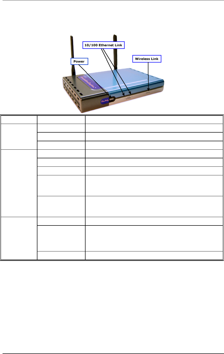
Front Panel/LEDs
LED Status Description
Off Power is not supplied to the EmulationEngine
On Power is supplied to the EmulationEngine
Power
Flashing Running a self test, loading software, or system errors
10/100: Off No Ethernet activity
100: On Green Indicates 100 Mbps Ethernet cable link
10: On Green Indicates 10 Mbps Ethernet cable link
100: Flashing
Green
The EmulationEngine is transmitting or receiving data on
the 100 Mbps Ethernet LAN. Blink rate is proportional to
network activity.
Ethernet Link
10/100
(See Note
below)
10: Flashing Green The EmulationEngine is transmitting or receiving data on
the 10 Mbps Ethernet LAN. Blink rate is proportional to
network activity.
Off Wireless link disabled
On Valid wireless link but the EmulationEngine is not joined
with a System Under Test or the EmulationEngine has lost
communication with a System Under Test and has not
joined with any other System Under Test.
Wireless Link
Flashing EmulationEngine has joined with a System Under Test.
NOTE: The Ethernet LED is normally ON while a link is detected.
It turns OFF when a packet is received or transmitted. The OFF
period is 50 milliseconds. If packets are being transmitted or
received every 50 milliseconds or faster (e.g., 20 packets per
seconds evenly spaced) for a sustained period, the LED will stay
off. This is done by the hardware and the timing/proportionality is
not adjustable.
Communication Machinery Corporation (CMC)
2-2 Rev #/Date: 2.0.0 Beta/07.17.03
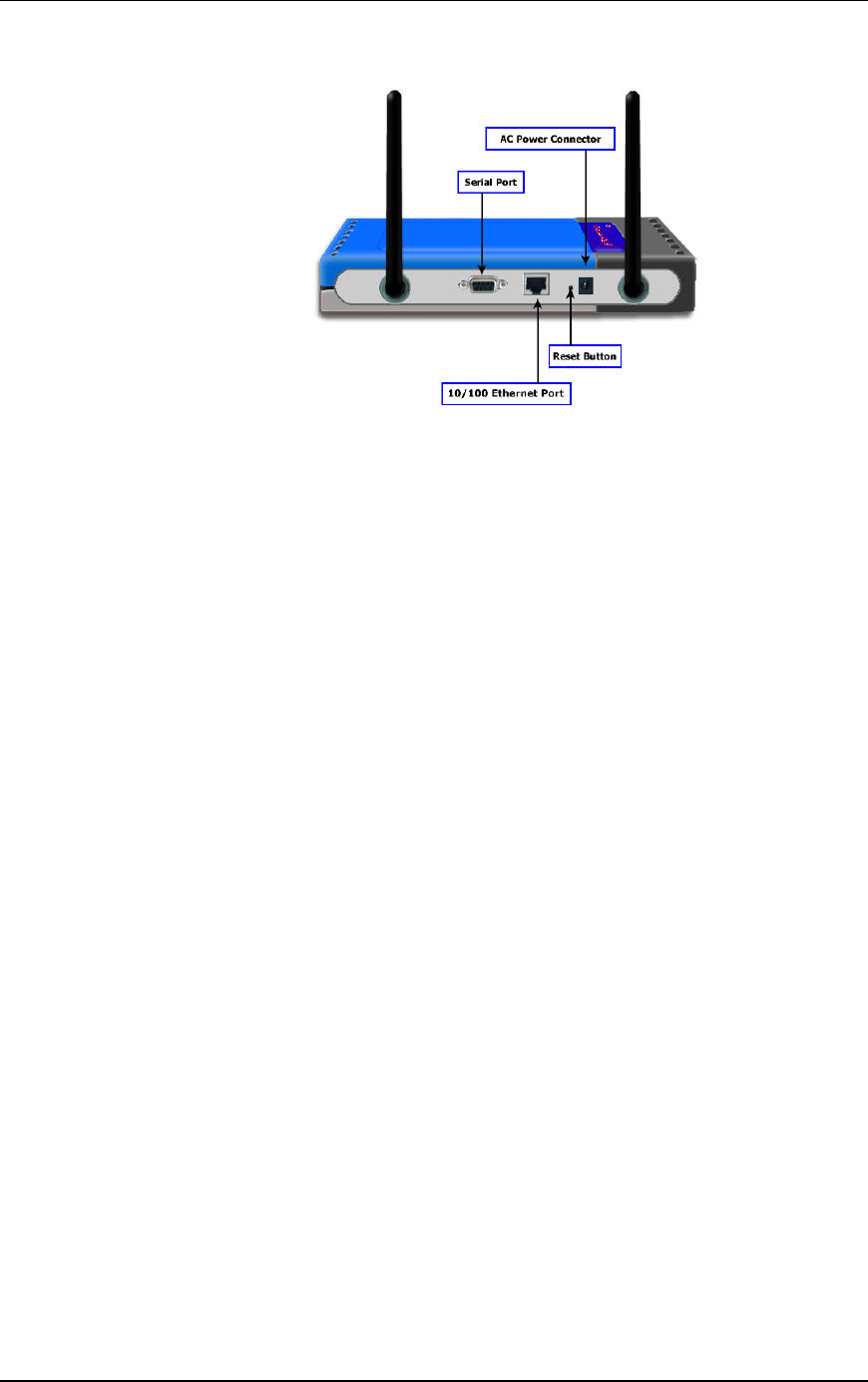
Back Panel
Connectors
10/100 Ethernet Connector: This connector provides 10/100
Mbps connectivity to a wired Ethernet LAN. It is used to connect a
command PC to the EmulationEngine.
Serial Port: This connector can also be used to connect a
command PC to the EmulationEngine. The configuration of the
serial port is: 9600 bps, 8 data bits, no parity, 1 stop bit, and no
flow control
AC Power Connector: This connector is used to connect the
EmulationEngine to the provided power supply.
Antennas
There are two antennas on the back of the device. The system
chooses the best antenna for transmit and receive. The antennas
can be swiveled 180 degrees and angled up or down to optimize
signal gain.
Reset Button
A recessed reset button is located between the Ethernet Connector
and Power Supply Connector on the back of the unit. It can be
used to perform a hard reset of the EmulationEngine. To perform
a hard reset, use a paper click to press the reset button.
EmulationEngine 11a/b/g User's Guide
Rev #/Date: 2.0.0 Beta/07.17.03 3-1
CHAPTER 3: Installation
Use the provided Power Adapter to supply power to the
EmulationEngine.
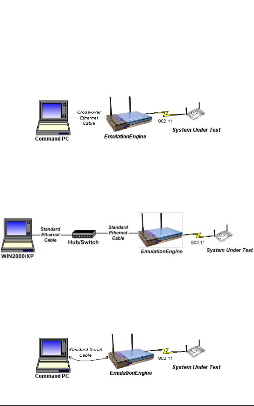
Connecting Directly to a Command PC
Connect one end of the supplied Ethernet crossover cable to the
Ethernet port on the command PC.
Connect the other end of the crossover cable to the RJ-45
Ethernet Connector on the EmulationEngine.
Connecting Through an Ethernet Hub/Switch
Connect one end of a standard Ethernet cable (not provided) to the
Ethernet port on the command PC. Connect the other end of the
cable to the Ethernet Connector on the Ethernet hub/switch.
Connect one end of a standard Ethernet cable to a port on the
hub/switch. Connect the other end of the cable to the Ethernet
Connector on the EmulationEngine.
Connecting to the Serial Port (Optional)
A standard straight serial cable is provided with the
EmulationEngine.
Connect the female connector end of the cable to a serial port on
the command PC.
Connect the male connector end of the cable to the serial port on
the EmulationEngine.

Communication Machinery Corporation (CMC)
3-2 Rev #/Date: 2.0.0 Beta/07.17.03
EmulationEngine 11a/b/g User's Guide
Rev #/Date: 2.0.0 Beta/07.17.03 4-1
CHAPTER 4: Initial Setup
For an Ethernet Port Connection
If the Command PC is attached to the Ethernet Port on the
EmulationEngine, complete the following steps to configure the
Command PC and access the EmulationEngine web-based user
interface or Command Line Interface (CLI):
1) Select Control Panel from the Start menu on the PC.
2) Double click on the Network Connections icon.
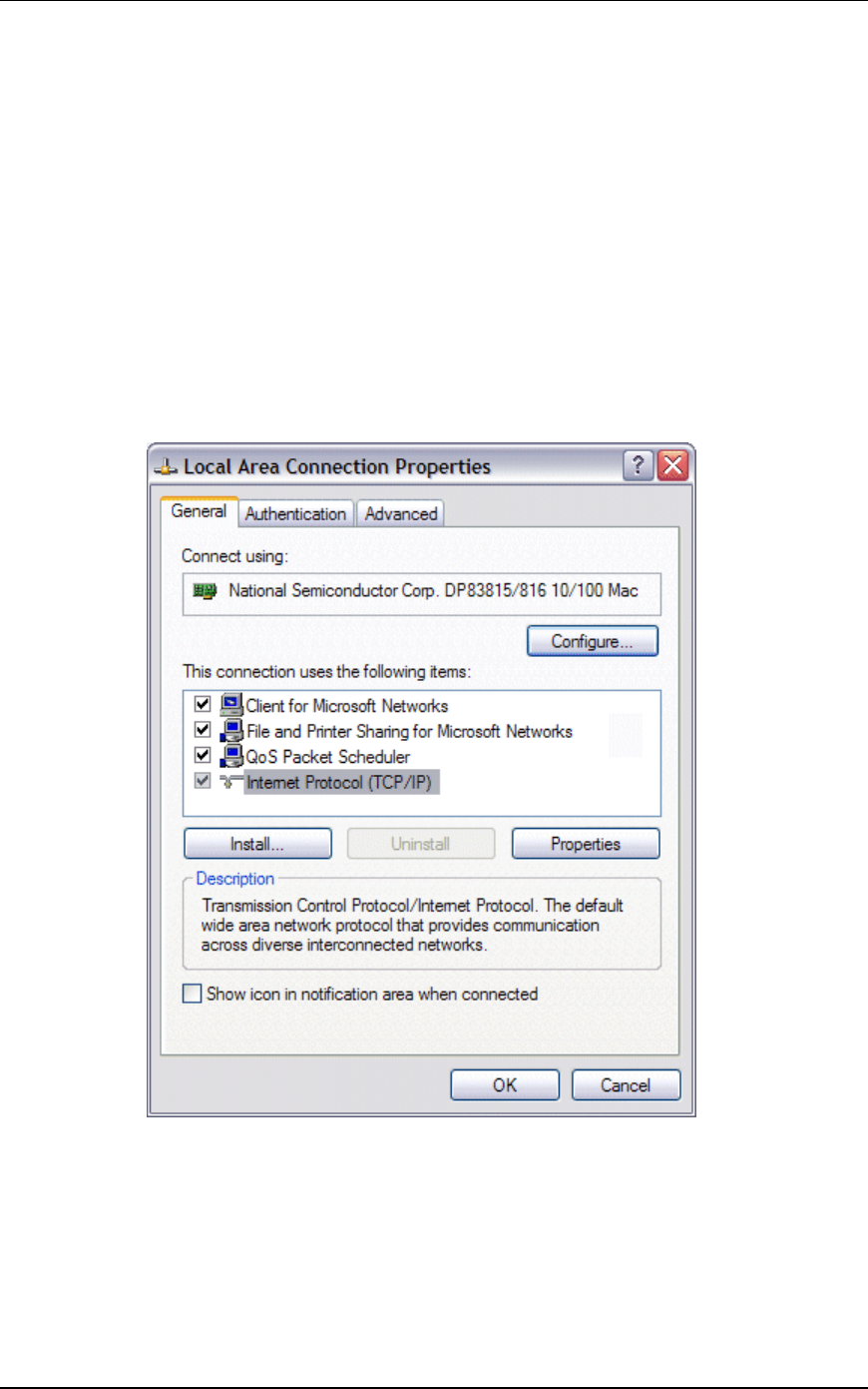
3) Right-click on the Local Area Connection icon for the Ethernet
controller that is connected to the EmulationEngine. Select
Properties from the right-click menu to display the Local Area
Connection Properties dialog.
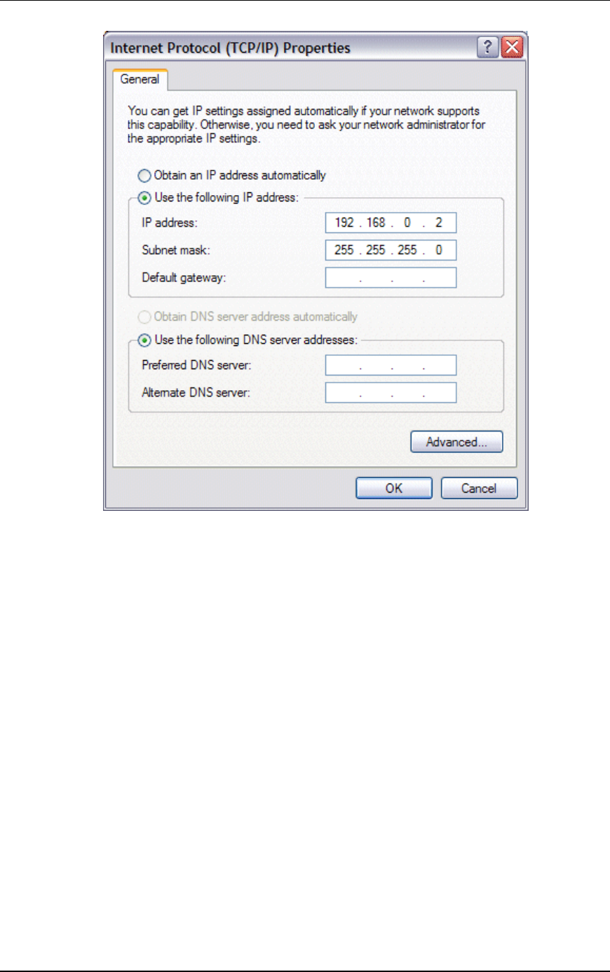
4) Select/highlight Internet Protocol (TCP/IP).
5) Click the Properties button to display the Internet Protocol
(TCP/IP) Properties dialog.
Communication Machinery Corporation (CMC)
4-2 Rev #/Date: 2.0.0 Beta/07.17.03
6) Select the “Use the following IP address” radio button and enter
the IP address for the Ethernet connection. Use an IP Address that
resides on the same IP subnet as the EmulationEngine. For
example, use 192.168.0.2 if you are using the EmulationEngine's
default IP address 192.168.0.50.
7) Click “OK” to close the Internet Protocol (TCP/IP) Properties
dialog.
8) Click the Close button in the Local Area Connection Properties
dialog.
You can access the EmulationEngine using one of the following
methods.
Web-Based User Interface: You can use a PC with Microsoft
Windows 2000/XP and Internet Explorer (Version 6.0 or higher) to
access the web-based user interface.
Launch Internet Explorer on the command PC.
Select Internet Options from the Tools menu. Select the Settings
button and make sure the "Every Visit to Page" radio button is
selected in the Settings dialog. This step is only required the first
time you use the web-based user interface.
EmulationEngine 11a/b/g User's Guide
Rev #/Date: 2.0.0 Beta/07.17.03 4-3
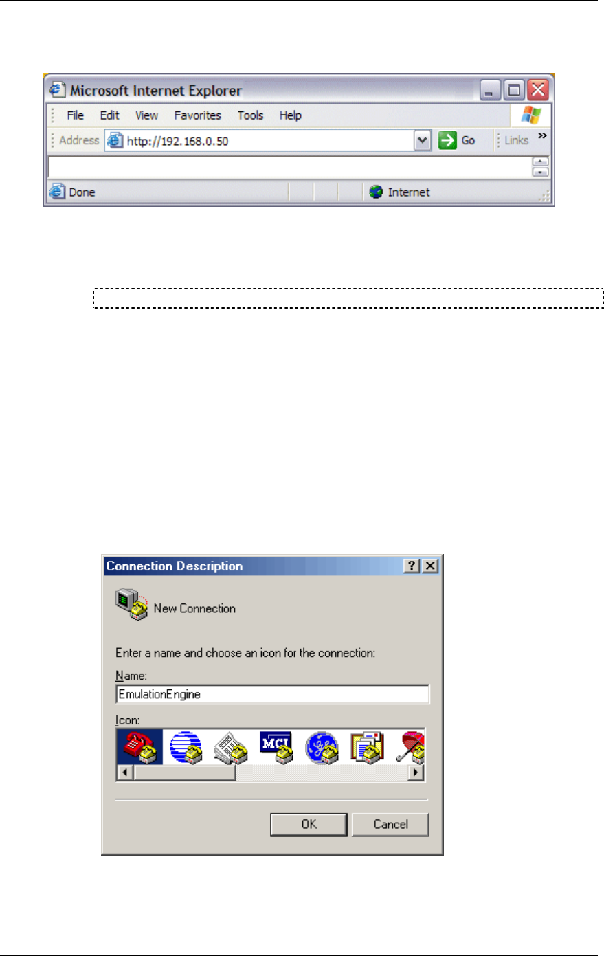
For initial setup, use the EmulationEngine's default IP address
192.168.0.50. Example:
Command Line Interface (CLI): You can use a PC that is
connected via Telnet to access the CLI. For initial setup, use the
EmulationEngine's default IP address 192.168.0.50 to establish a
Telnet connection. Example:
telnet 192.168.0.50
See Chapter 5 for information about using the web-based user
interface. See Chapter 6 for information about using the CLI.
For a Serial Port Connection
If the command PC is connected to the EmulationEngine via the
serial port, the web-based user interface is not available. Use the
following procedure to configure the Command PC and access the
EmulationEngine Command Line Interface (CLI):
1) At the Command PC, launch a terminal-emulation program
such as HyperTerminal.
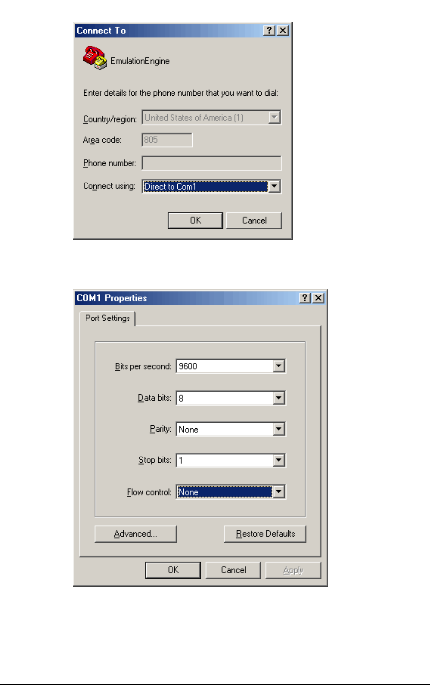
2) In the Connection Description dialog, enter a name for the
connection in the Name field (e.g., EmulationEngine).
3) Choose an icon for the connection and click OK to display the
Connect To dialog:
Communication Machinery Corporation (CMC)
4-4 Rev #/Date: 2.0.0 Beta/07.17.03
4) Select the COM port that is connected to the EmulationEngine
from the “Connect using” list box. Click OK to display the COM
properties dialog:
5) Set the COM port settings as shown in this dialog: Bits per
second: 9600, Data bits: 8, Parity: None, Stop bits: 1, Flow
control: None.
6) Click OK to close the COM properties dialog.

EmulationEngine 11a/b/g User's Guide
Rev #/Date: 2.0.0 Beta/07.17.03 4-5
The POST (Power On Self-Test) appears on the HyperTerminal
screen a few seconds after the EmulationEngine is connected to
the power source.
POST...
Memory test : passed
Ethernet MAC register test : passed
Ethernet PHY register test : passed
Ethernet interrupt test : passed
Pl
Atheros AP 8245 Reference Design version 2.3.0.70
0
auto-booting...
Attaching to TFFS... done.
Loading /fl/ee22dbg.sys...1212444
Starting at 0x480000...
Reading Configuration File "/fl/eecfg".
Configuration file checksum: 1ac34 is good
Please check the ethernet cable!
dp0 loaded
Base address = 88010000, irq 1
Attach AR5212 19 caf7b8
wlan revisions: mac 5.6 phy 4.1 analog 1.7
ar0 loaded
Attaching interface lo0...done
Adding 4986 symbols for standalone.
VxWorks
Copyright 1984-1998 Wind River Systems, Inc.
CPU: Atheros AP 8245 Reference Design
VxWorks: 5.4.2
BSP version: 1.0/0
Creation date: Jul 7 2003
WDB: Ready.
Starting WLAN ...
Starting quick passive scan ...
Passive scanning 2.4GHz 54Mbps channels for 6 seconds...
CMC EmulationEngine Ready
EE login:
When the EE login prompt is displayed, use the information in
Chapter 6 to log in and access the EmulationEngine CLI.

Communication Machinery Corporation (CMC)
4-6 Rev #/Date: 2.0.0 Beta/07.17.03
EmulationEngine 11a/b/g User's Guide
Rev #/Date: 2.0.0 Beta/07.17.03 5-1
CHAPTER 5: The Web-Based User Interface
System Requirements
The command PC must be equipped with:
Microsoft Windows 2000/XP
Microsoft Internet Explorer Version 6.0 or higher
Recommended Memory: 256 MB
Recommended Virtual Memory: 300 MB
Recommended Processor Speed: PIII 700 MHz
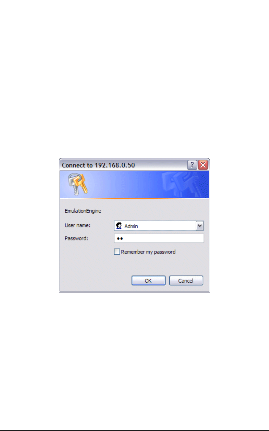
Start-Up/Login
Launch Internet Explorer.
Enter the IP address of the EmulationEngine in the URL address
field of the browser (e.g., http://192.168.0.50).
Enter your user name and password and select “OK” to access the
EmulationEngine web server. The default user name is "Admin".
The default password is "EE". The user name and password are
case sensitive. After successful log in, a splash page will be
displayed for a few seconds:
Communication Machinery Corporation (CMC)
5-2 Rev #/Date: 2.0.0 Beta/07.17.03
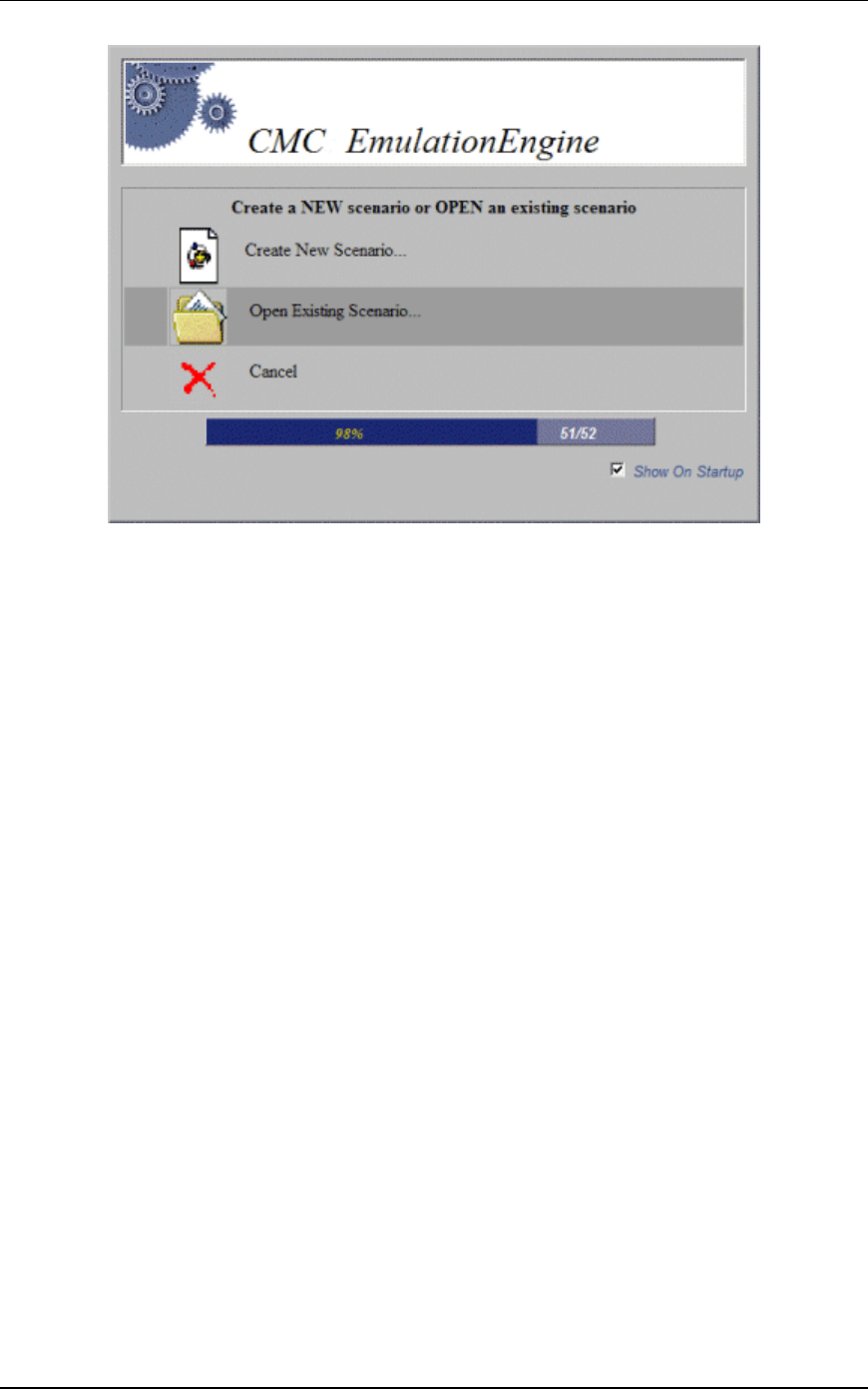
Choosing a Scenario/Test
If the EmulationEngine already contains virtual station
definitions, the following dialog will be displayed:
Select “Yes” to build a scenario in the user interface that is based
on the virtual stations that are already defined in the
EmulationEngine.
Select “No” to delete the virtual station definitions in the
EmulationEngine and create a new empty scenario.
Select “Cancel” to retain the virtual stations in the
EmulationEngine but do not create a new empty scenario. When
the main page is displayed, you can display the Scenario
Summary Report, Group Summary Report, and Event Log for
these existing virtual stations.
Following a Yes, No, or Cancel selection, the web-based user
interface main page is displayed.
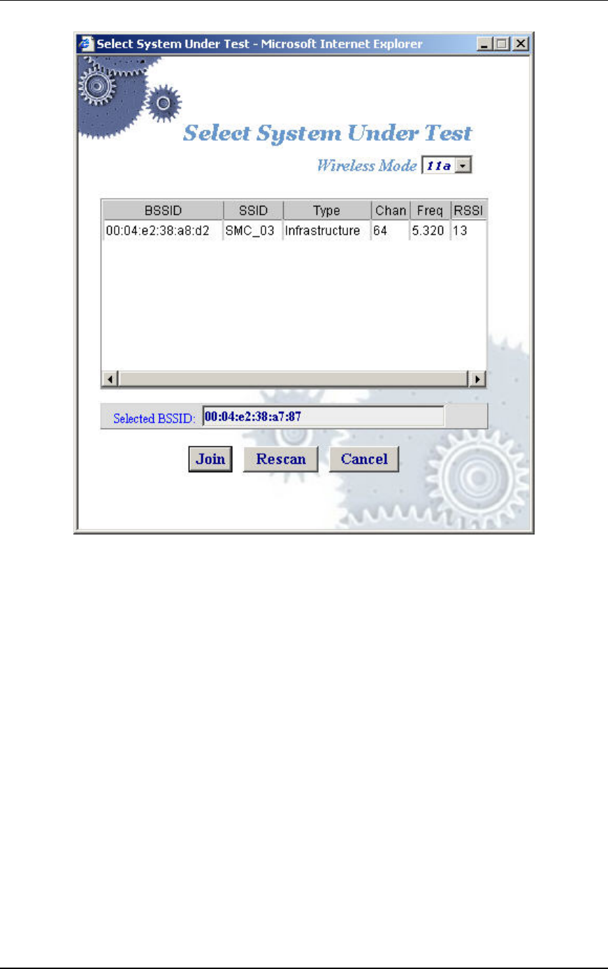
If there are no virtual station definition in the EmulationEngine
and the welcome screen has not been disabled in the UI
Configuration dialog (see Configuration->Preferences), the
following screen will be displayed:
EmulationEngine 11a/b/g User's Guide
Rev #/Date: 2.0.0 Beta/07.17.03 5-3
Select “Create New Scenario” to select a System Under Test. When
you create a new scenario, the user interface provides a list of
active Basic Service Set IDs (BSSIDs) that have been detected.
Select “Open Existing Scenario” to choose from a list of scenario
files that have already been created. When you open an existing
scenario, the EmulationEngine information is already stored with
the scenario file.
Select “Cancel” to exit this dialog. You can create a new scenario
or open an existing scenario in the main page.
Uncheck the “Show On Startup” checkbox if you do not want to
show this screen each time you access the EmulationEngine web
server. You can restore this screen on start-up in the UI
Configuration dialog (See Configuration->Preferences).
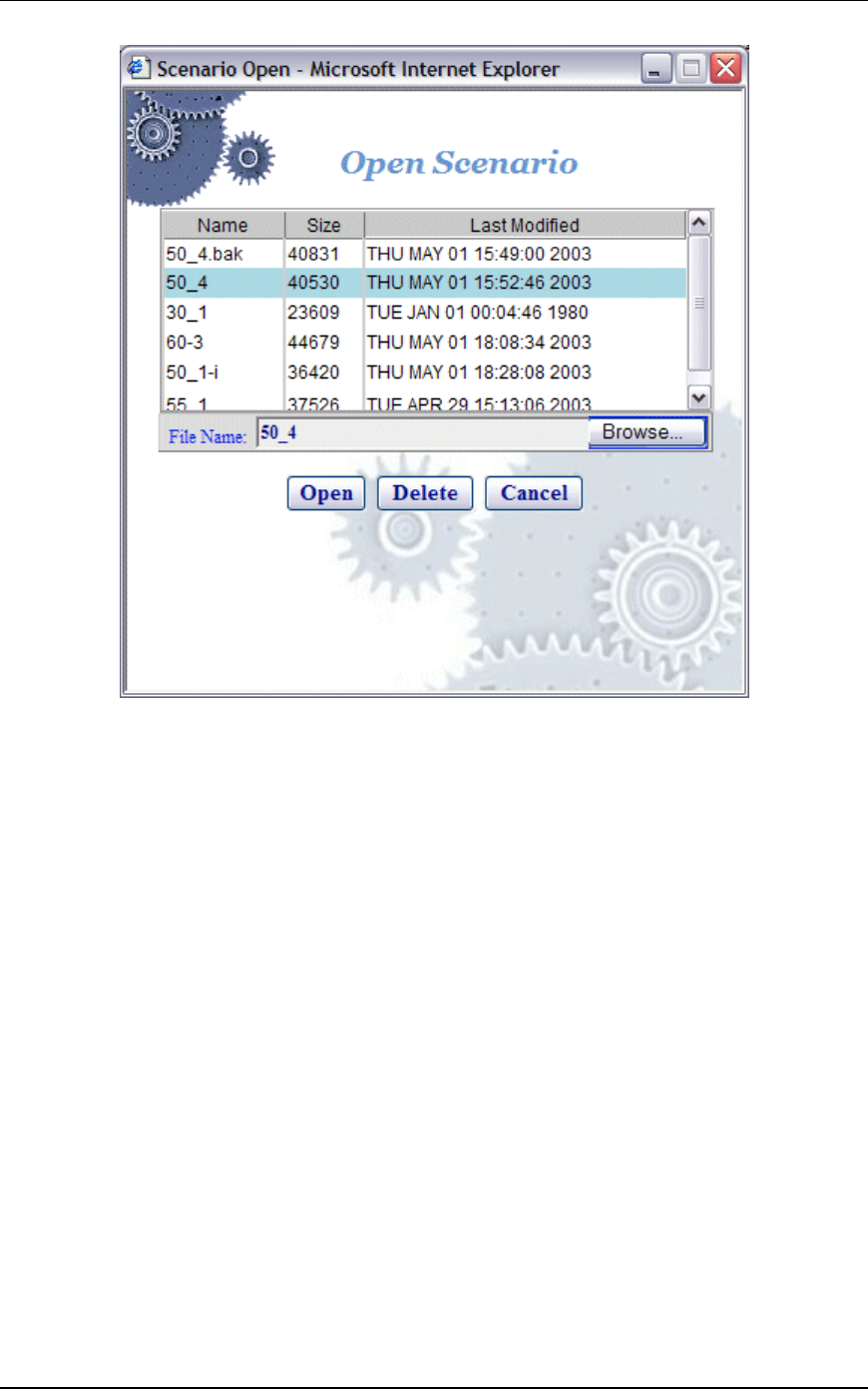
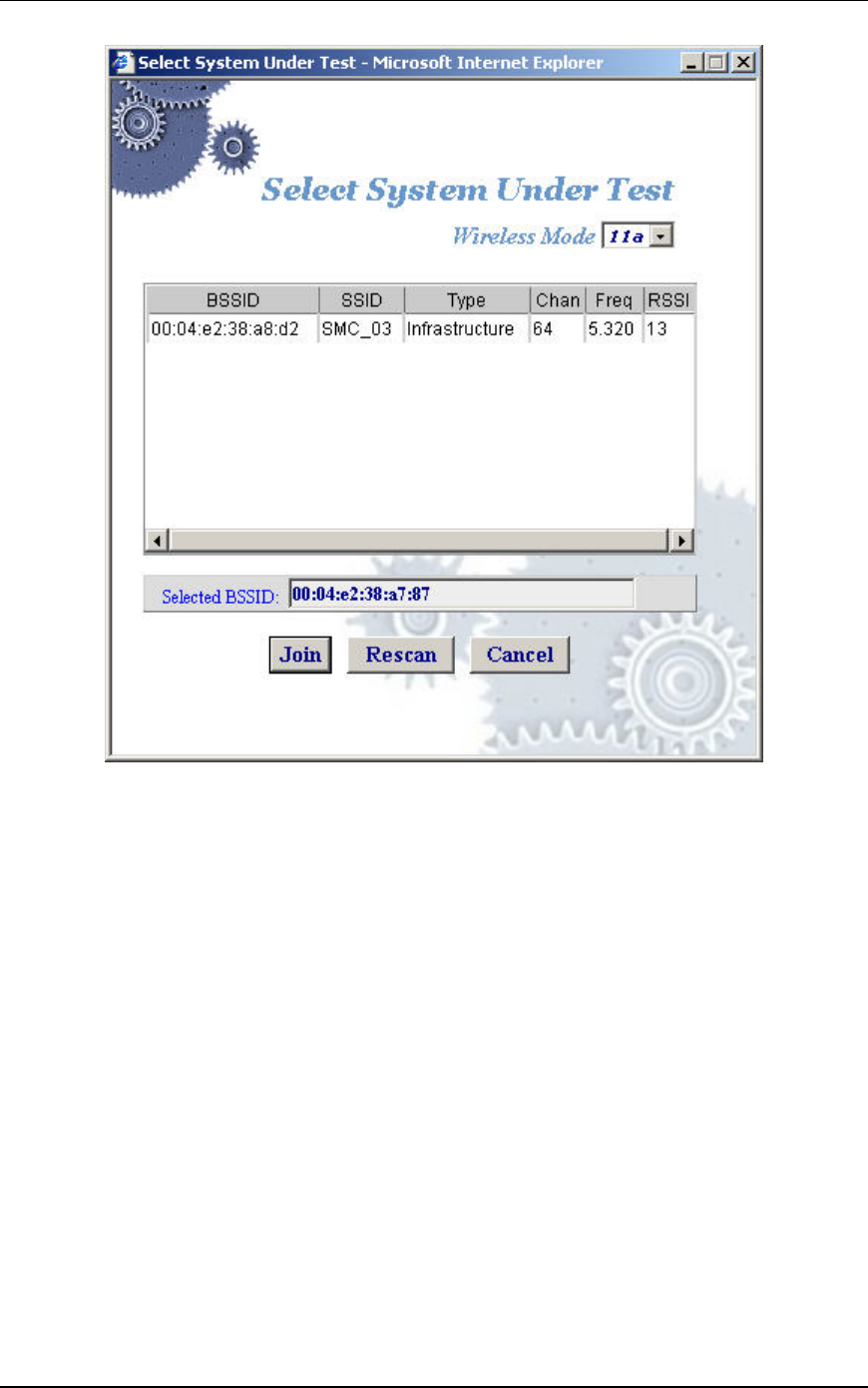
Create New Scenario
If you selected “Create New Scenario” in the welcome screen and
have not previously joined with a System Under Test, the Select
System Under Test dialog will be displayed:
Communication Machinery Corporation (CMC)
5-4 Rev #/Date: 2.0.0 Beta/07.17.03
Wireless Mode: This field shows the EmulationEngine’s current
wireless mode (11a, 11b, or 11g). You can select a different
wireless mode from the list box. The web-based user interface will
issue a command to the EmulationEngine to change its wireless
mode and scan for compatible systems. The results of the new
scan will be reflected in the BSSIDs in the list box.
Select a BSSID in the list box. The selected BSSID will be shown
in the "Selected BSSID" text box.
Select “Join” to join with the selected target system.
Select “Rescan” to update the list of BSSIDs. This selection will
cause the EmulationEngine to scan for Basic Service Set IDs.
Select “Cancel” to close this dialog without selecting a target
system. You can select a target system and create or open an
existing scenario in the main page.
Open Existing Scenario
If you selected “Open Existing Scenario” in the welcome screen
and have not joined with a target system, the Select System Under
Test dialog is displayed as described above. After you have joined
with a target system, the Open Scenario dialog will be displayed:
EmulationEngine 11a/b/g User's Guide
Rev #/Date: 2.0.0 Beta/07.17.03 5-5
The list box shows a list of scenario files on the EmulationEngine.
Select “Browse” to select from scenario files stored on the
command PC. Click on a file name in the list of scenario files.
Select “Open” to open the selected scenario file and continue.
Select “Delete” to delete the selected file.
Select “Cancel” to close this dialog without opening a scenario file.
You can create a new scenario or open an existing scenario in the
main page.
The Main Page
The following illustration shows the format of the main page that
is displayed after you select any of the options in start-up dialogs:
Communication Machinery Corporation (CMC)
5-6 Rev #/Date: 2.0.0 Beta/07.17.03
The content of this page will be different depending on whether
you created a new scenario, opened an existing scenario, or
cancelled/closed any of the start-up dialogs. This example page
shows an existing scenario where one group is defined. This
section of the page will be blank (No Scenario Defined) if a
scenario has not been created.
If you successfully opened a scenario file or chose to use one that
is already defined in the EmulationEngine, you can continue with
the testing functions that are available in the menus and toolbar.
See “Running a Test”. If you selected "Create New Scenario", you
must create a group of virtual stations. If you selected "Cancel",
you must select and join with a target system and create a new
scenario that contains one or more group(s) of one or more virtual
station(s).
Creating an Internal Mode/Ping Test
For a simple internal mode/ping test, complete the following
steps.
Step 1) If you have already opened or created a scenario, skip to
step 2. Otherwise, select "New Scenario" from the File menu to
show the Select System Under Test dialog.
EmulationEngine 11a/b/g User's Guide
Rev #/Date: 2.0.0 Beta/07.17.03 5-7
Wireless Mode: This field shows the EmulationEngine’s current
wireless mode (11a, 11b, or 11g). You can select a different
wireless mode from the list box. The web-based user interface will
issue a command to the EmulationEngine to change its wireless
mode and scan for compatible systems. The results of the new
scan will be reflected in the BSSIDs in the list box.
Click on a BSSID in the list box and click “Join” to continue.
Step 2) Select New Group from the vSTA side bar to show the New
Emulation Group dialog.
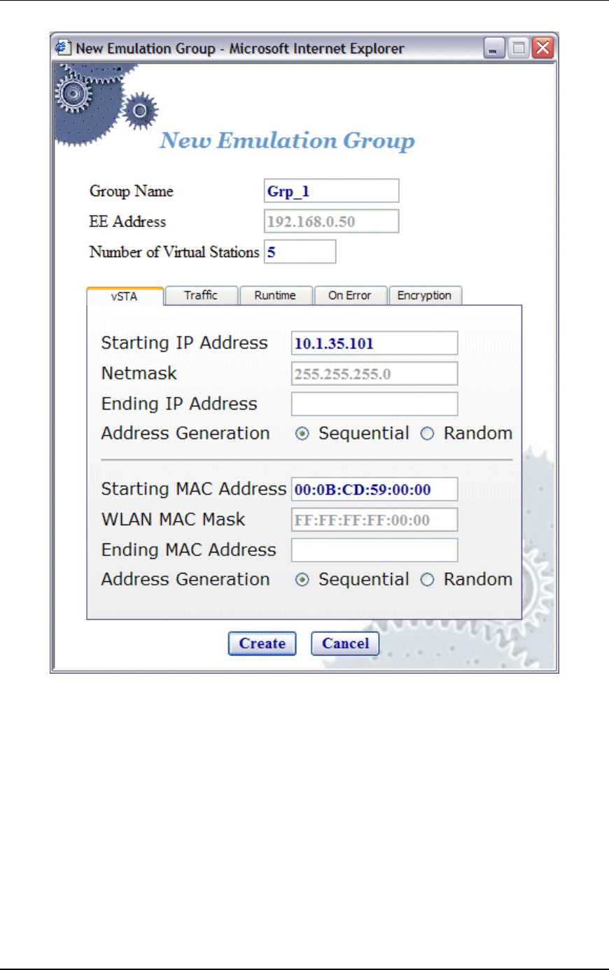
Communication Machinery Corporation (CMC)
5-8 Rev #/Date: 2.0.0 Beta/07.17.03
Step 3) Enter an IP address in the Starting IP Address field to
define the starting IP address to be used by virtual stations that
are created in this scenario. Virtual stations will be created with
unique IP addresses, sequentially or randomly, based on this
starting IP address.
Step 4) Select the Traffic tab.
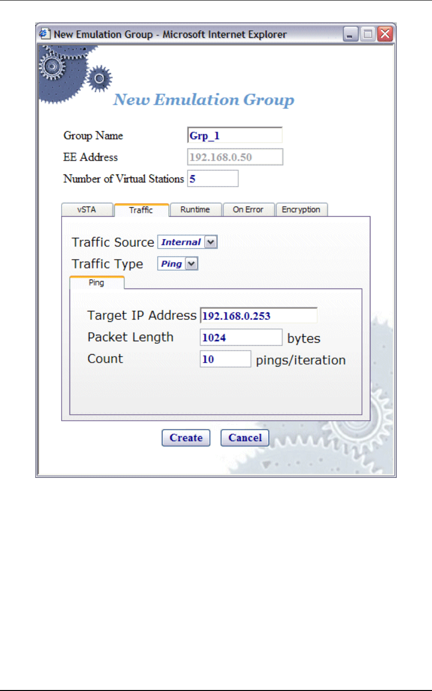
EmulationEngine 11a/b/g User's Guide
Rev #/Date: 2.0.0 Beta/07.17.03 5-9
Step 5) Make sure the Target IP Address field is set to the address
of a target server to be pinged. Click “Create” to create a group
with five virtual stations. See "vSTA->New Group" for more
information about defining and editing groups and virtual stations
in a scenario.
Creating an External Mode Test
For an external mode test, a third-party load generator outside the
EmulationEngine must be set up to provide the traffic to be
forwarded to the System Under Test. Use the documentation
provided by the manufacturer to set up the load generator. See the
EmulationEngine Test Set-Up & Configuration Guide for more
information about setting up an external mode test. The
procedures for creating an internal or external mode test are
Communication Machinery Corporation (CMC)
5-10 Rev #/Date: 2.0.0 Beta/07.17.03
almost identical. To create the external mode test, complete steps
1) through 4) as described above for “Creating an Internal Mode
Test”. In Step 5), select “External” in the “Traffic Source” field and
click the Create button in the New Emulation Group dialog.
Running a Test
Click this button in the toolbar to run the scenario/test for
all groups and all virtual stations in a scenario.
Click this button in the toolbar to run a test for selected
virtual stations or groups.
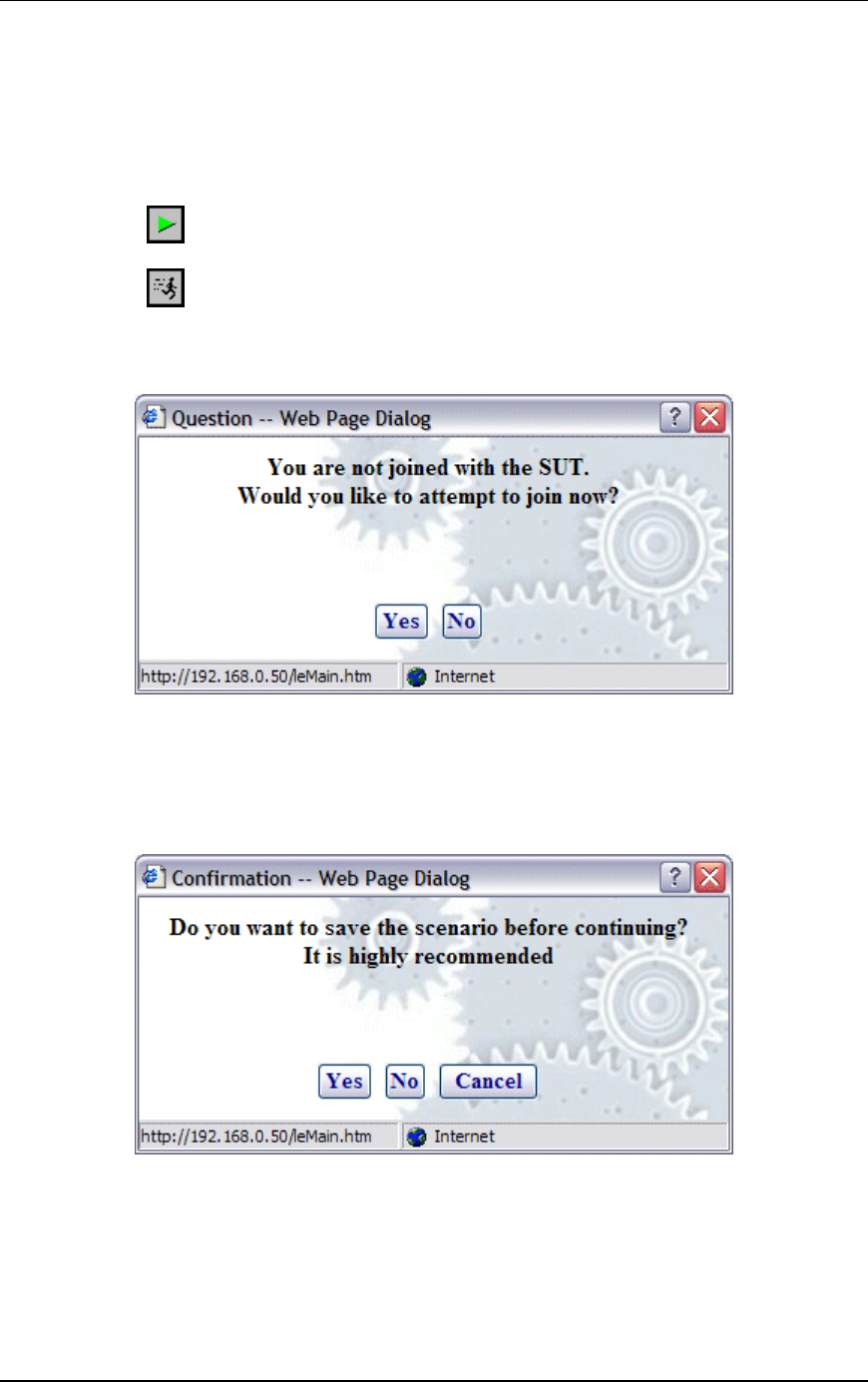
If you created a new scenario and have not yet joined with a target
system, the following dialog will be displayed:
Click “Yes” to show the Select System Under Test dialog and join
with the System Under Test.
If you created a new scenario and have not saved it using the Save
Scenario option in the File menu, a dialog will prompt you to save
the scenario.
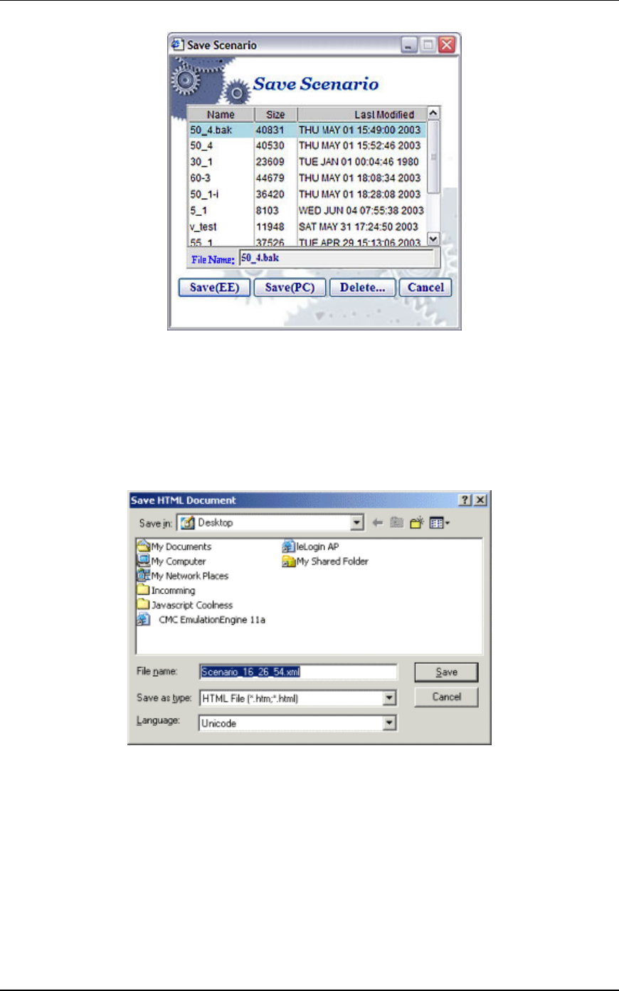
Select “Yes” to save the scenario file. The Save Scenario dialog is
displayed:
EmulationEngine 11a/b/g User's Guide
Rev #/Date: 2.0.0 Beta/07.17.03 5-11
Type a name in the File Name field. Do not use colon (:), asterisk
(*), question mark (?), quotes (“”), less-than/greater than signs (<
>), vertical bar (|), or spaces in a file name.
Select “Save(EE)” to save the scenario in the EmulationEngine’s
flash file system.
Select “Save(PC)” to save the scenario on the command PC. A
standard save dialog will be displayed.
Type a name in the File Name field. Do not use colon (:), asterisk
(*), question mark (?), quotes (“”), less-than/greater than signs (<
>), vertical bar (|), or spaces in a file name. A disk drive
specification (e.g., C:/, D:/) is optional. Select “Save” to save the
scenario at the designated location on the command PC.
The virtual stations will start running a few seconds after the
scenario has been saved. As the test runs, you will see the "Run
State" in the group grid go through the 802.11 states: configure,
initialize, authenticate, associate, and run. When an internal
mode/ping test is complete, the "Run State" will display "Done".
Communication Machinery Corporation (CMC)
5-12 Rev #/Date: 2.0.0 Beta/07.17.03
NOTE: Any interaction with a running test can affect the operation
of the test which may result in skewed statistics.
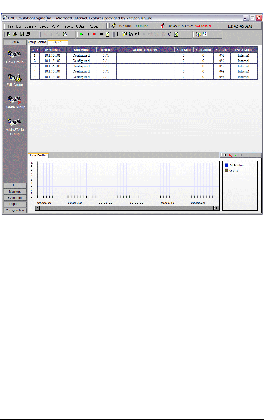
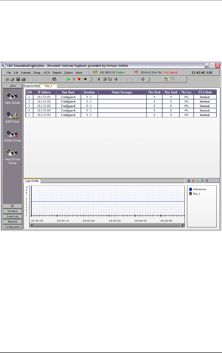
About/Using the Main Page
The following illustration shows the general format of the main
page where a scenario with one group of virtual stations has been
defined and the group tab (Grp_1) is selected:
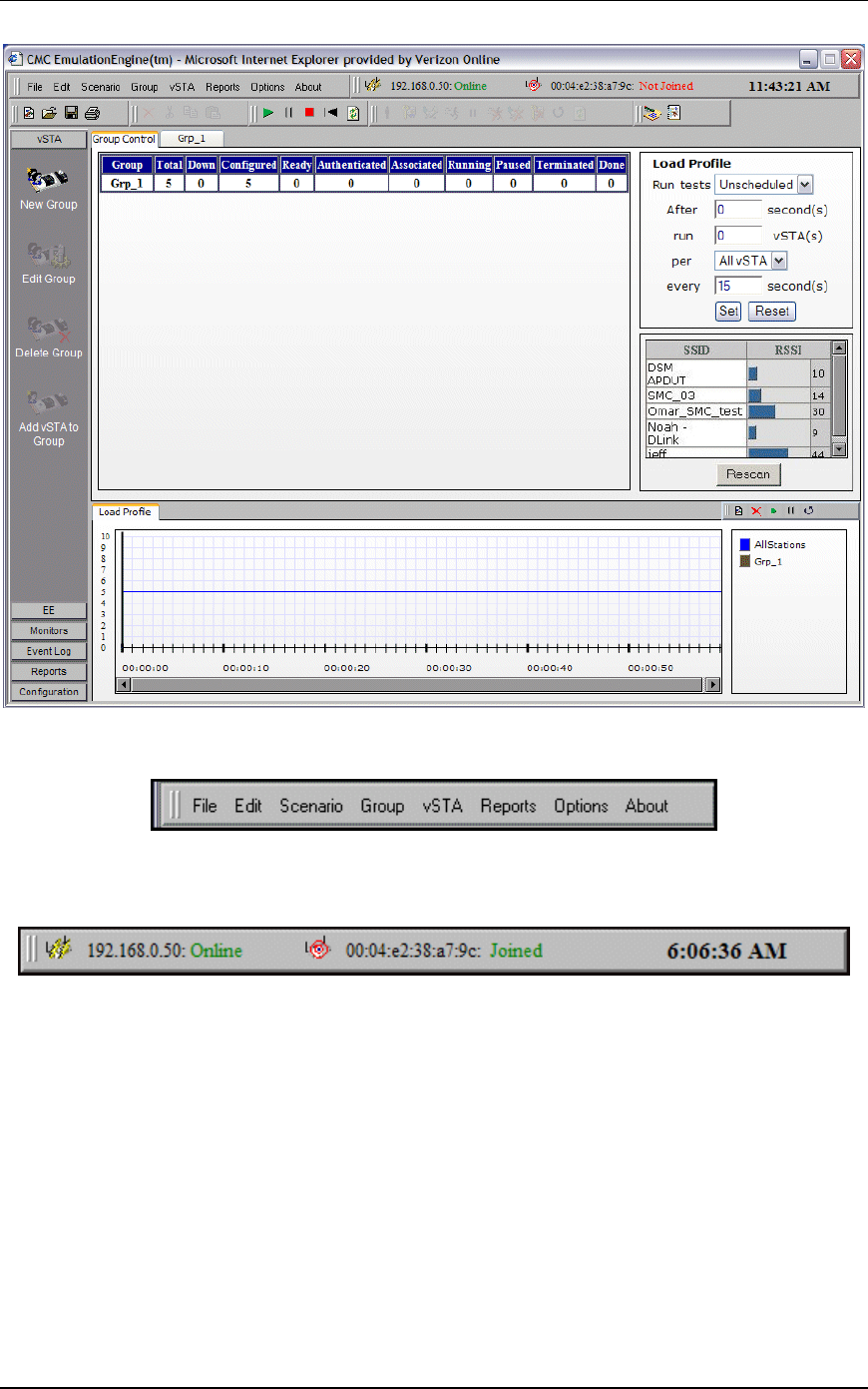
When the “Group Control” tab is selected, the main page will show
the Load Profile and a list of devices that have been discovered (if
any) in a scan:
EmulationEngine 11a/b/g User's Guide
Rev #/Date: 2.0.0 Beta/07.17.03 5-13
Menu Toolbar: The top-left toolbar at the top of the page is a
drop-down menu bar of all EmulationEngine functions.
Status Toolbar: The top-right toolbar shows the status of the
EmulationEngine, the System Under Test and the current time on
the command PC.
The status (e.g., Online) next to the EmulationEngine IP Address
Address indicates the current status of the EmulationEngine with
the web-based user interface. This status may intermittently
display “Busy” or “Offline”. If the Busy or Offline status displays
frequently or for extended periods of time, check the Polling
Interval and Polling Timeout values in the Configure
EmulationEngine dialog (see EE->Configure EE). Also see Chapter
9, Troubleshooting/EmulationEngine Busy or Not Responding.
The status (e.g., Joined) next to the BSSID/MAC address indicates
the current status of the EmulationEngine with a System Under
Test.
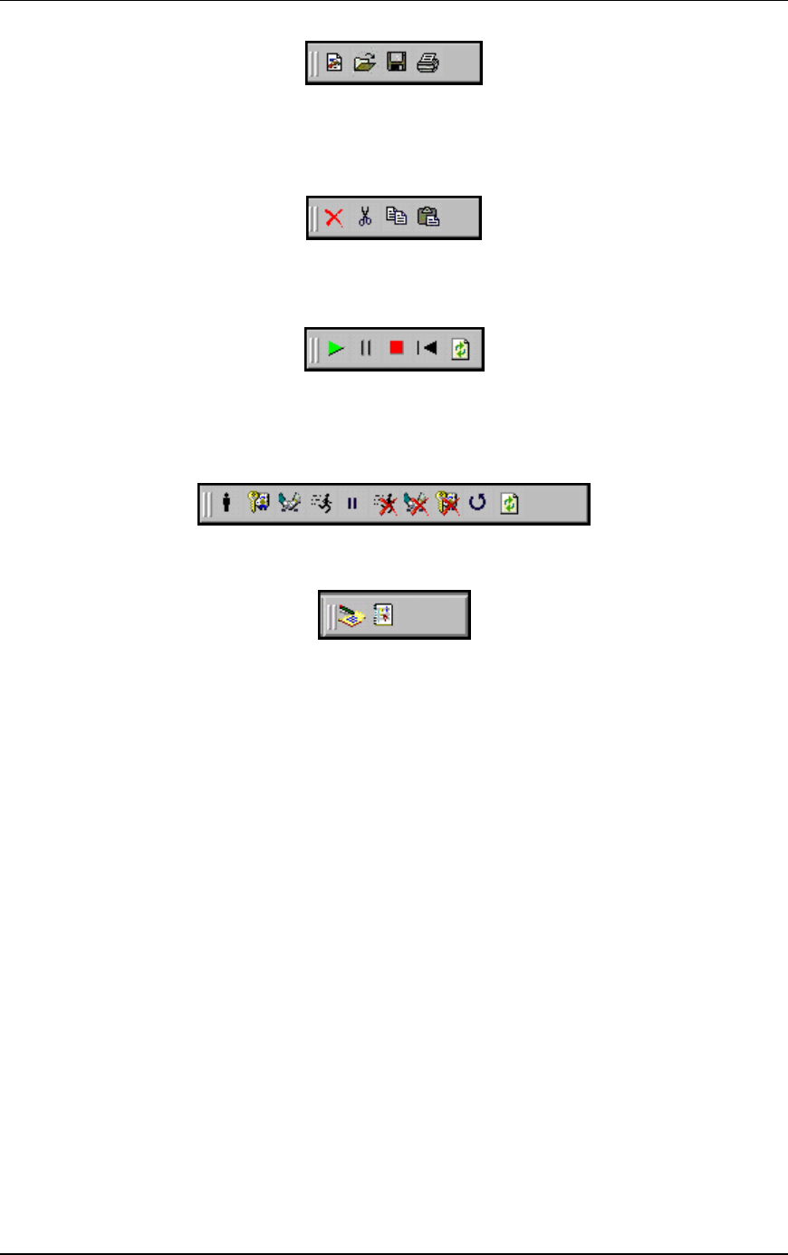
File Toolbar: This toolbar is used to create, open, save and print
scenarios.
Communication Machinery Corporation (CMC)
5-14 Rev #/Date: 2.0.0 Beta/07.17.03
Edit Toolbar: This toolbar is used to delete, cut, copy and paste
virtual stations within and between groups. It can also be used to
delete groups when a group is selected in the group control
tab/table.
Scenario Toolbar: The buttons in this section of the toolbar can
be used to run, pause, stop, restart, or refresh the entire scenario
of all virtual stations.
vSTA Toolbar: The buttons in this toolbar are used to initialize,
authenticate, associate, run, pause, stop, disassociate,
deauthenticate, restart, or refresh selected virtual stations or
groups of virtual stations.
Reports Toolbar: The buttons in this toolbar are used to view
reports and the event log:
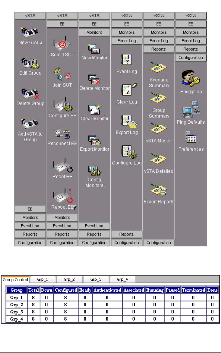
Side Bar Buttons: The buttons in the side bar provide access to
most virtual station, engine, monitoring, logging and report
functions as well as user interface and encryption configuration.
EmulationEngine 11a/b/g User's Guide
Rev #/Date: 2.0.0 Beta/07.17.03 5-15
Group Control Grid
When the Group Control tab is selected, the table shows the
status of each group and its associated virtual stations:

Communication Machinery Corporation (CMC)
5-16 Rev #/Date: 2.0.0 Beta/07.17.03
Group: This field displays the name of each group. The name is
assigned in the New Emulation Group dialog (See vSTA->New
Group).
The remaining fields in the group line are counters that show the
state of each group’s virtual stations during a test.
Total: This field shows the total number of virtual stations in each
group.
Down: This field shows the total number of virtual stations in a
group that have not been configured in the EmulationEngine and
are in a “down” state.
Configured: This field shows the total number of virtual stations in
each group that have been configured in the EmulationEngine.
Ready: This field shows the total number of virtual stations in each
group that are ready (in the initialized state) to begin testing.
These virtual stations have been initialized in the
EmulationEngine.
Authenticated: This field shows the total number of virtual stations
in each group that have authenticated with the System Under
Test.
Associated: This field shows the total number of virtual stations in
each group that have associated with the System Under Test.
Running: This field shows the total number of virtual stations in
each group that are currently performing an operation defined by
the scenario. The operation that is being performed depends on
whether the virtual stations are configured for internal or external
traffic generation.
Paused: This field shows the total number of virtual stations in
each group that have paused in their execution.
Terminated: This field shows the total number of virtual stations in
each group that have been terminated. These virtual stations
must be reset before they can be used again.
Done: This field shows the total number of virtual stations in each
group that have completed their run of an internal mode/ping
test. This field will not be incremented for virtual stations that are
running an external mode test or an internal mode test with
infinite iterations.
Group Tabs: Each group defined in the scenario has its own tab.
When an individual group tab is selected, the table shows details
of each virtual station in the group.

EmulationEngine 11a/b/g User's Guide
Rev #/Date: 2.0.0 Beta/07.17.03 5-17
GID: The global ID is a unique ID that is assigned by the
EmulationEngine to each virtual station in a scenario group. It is
a unique ID across all groups in the EmulationEngine.
IP Address: This field shows each virtual station's IP Address.
Run State: This column shows the current state of each virtual
station in the scenario group (i.e., Initializing, Authenticating,
Authenticated, Associating, etc.).
Iteration: The two numbers in this column show the current
iteration of the test that a virtual station is running or has
completed and the number of iterations that are configured for the
virtual station (e.g., 5/10 = 5 iterations have been completed/10
iterations are to be run). These numbers can be a value in the
range zero (0) to 9999 or Infinite.
Status Messages: This column shows status and/or error messages
returned by the EmulationEngine for each virtual station in the
scenario group. See Appendix D for a list of messages that may be
displayed in this column.
Pkts Rcvd: This column shows the total number of packets received
by each virtual station in this group.
Pkts Xmts: This column shows the total number of packets
transmitted by each virtual station in this group.
Pkt Loss: This column shows the percentage of packet loss for each
virtual station in this group.
vSTA Mode: This column shows the traffic generation mode
(Internal or External) of each virtual station in the scenario group.
You can select one or more line items/virtual stations in the table
and choose a menu item or toolbar button to execute a command
for an individual or multiple virtual stations.
You can double click on a virtual station line item in the table to
display the Edit Virtual Station dialog:

Communication Machinery Corporation (CMC)
5-18 Rev #/Date: 2.0.0 Beta/07.17.03
See vSTA->Add New vSTA to Group for information about the
fields in this dialog.
You can right click on selected virtual stations to display the vSTA
menu. Any menu option will affect the selected virtual station(s).
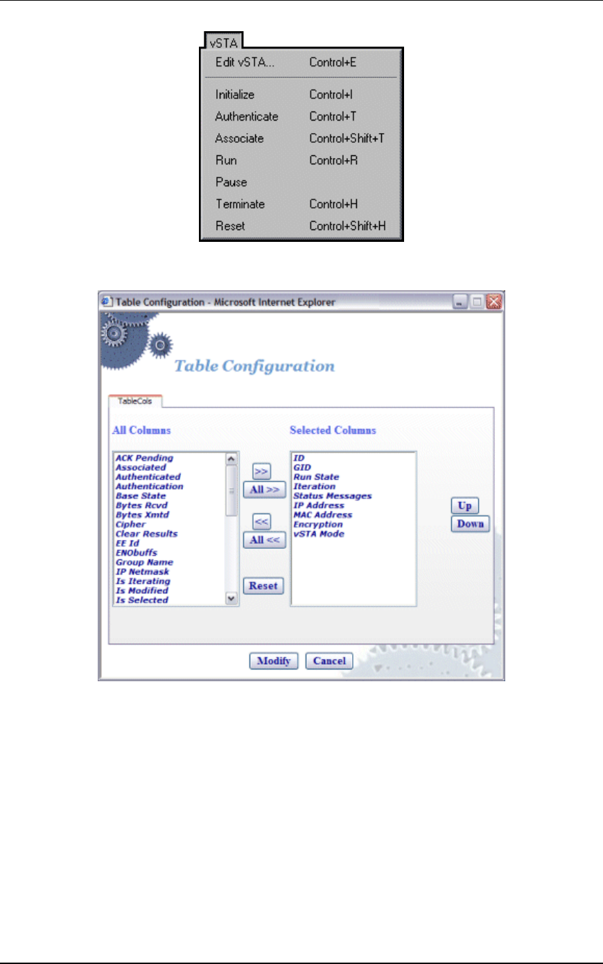
EmulationEngine 11a/b/g User's Guide
Rev #/Date: 2.0.0 Beta/07.17.03 5-19
Group Tab Columns: Within a group, you can double click on the
table heading to configure the columns that are displayed.
Select one or more items in the All Columns list box and click the
[>>] button to move them to the Selected Columns list box. Click
“Modify” to add the columns to the group table. Select “Reset” to
return the columns to their default setting.
Load Profile
The Load Profile section of the page can be used to automatically
execute scenarios at scheduled intervals.
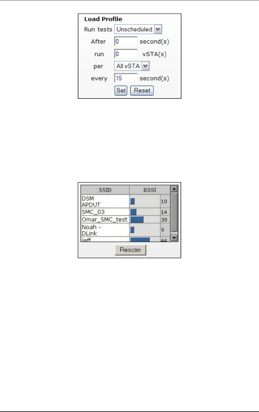
Communication Machinery Corporation (CMC)
5-20 Rev #/Date: 2.0.0 Beta/07.17.03
When automatic scheduling is defined, the grid below the
Scheduling/Group table will chart the status of each virtual
station over the period of the test. See "Using Load Profiles" below
for more information about using this feature.
Target Systems
Below Load Profile, the main page displays a list of target systems
and their signal strength in relationship to the EmulationEngine.
Target systems with a higher signal strength value have a
better/higher transmission rate to the EmulationEngine.
You can select “Rescan” to instruct the EmulationEngine to rescan
for all systems. The devices shown in this list box will be displayed
in the Select System Under Test dialog where you can choose a
system to test.
Load Profile/Monitor Graphs
The bottom half of the web page is reserved for charts that
graphically illustrate a load profile and monitor test results. When
the Load Profile tab is selected, a graph shows the loading profile
based on an active Load Profile.
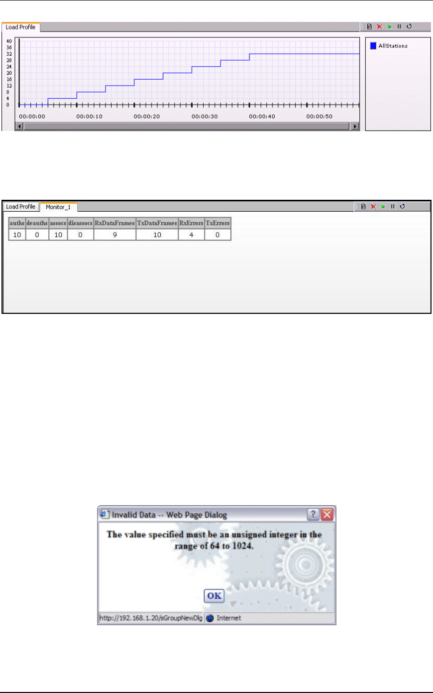
EmulationEngine 11a/b/g User's Guide
Rev #/Date: 2.0.0 Beta/07.17.03 5-21
See "Using Load Profiles" below for more information about how to
set up a Load Profile.
If multiple monitors have been defined, use the horizontal tabs at
the top of this section of the page to select and show each monitor.
A maximum of four monitors can be defined in each scenario. The
toolbar in the top-right corner of the monitor area can be used to
define a new monitor, delete a monitor, run a paused monitor,
pause a running monitor, and clear a monitor’s display. See
"Monitors Side Bar" for more information about this section of the
page.
Range Checking/Error Messages
In the dialogs described later in this chapter, the user interface
will verify all entries that require values within a specified range. If
a field can contain a very large number, do not enter commas (,)
for values larger than 999 (e.g., use 1000 rather than 1,000). If
you use an invalid character in a field or specify a value that is not
within range, a dialog will tell you the allowable range. Example:
When an Invalid Data dialog is displayed, click “OK” and reenter a
value that is within the allowable range for the field.
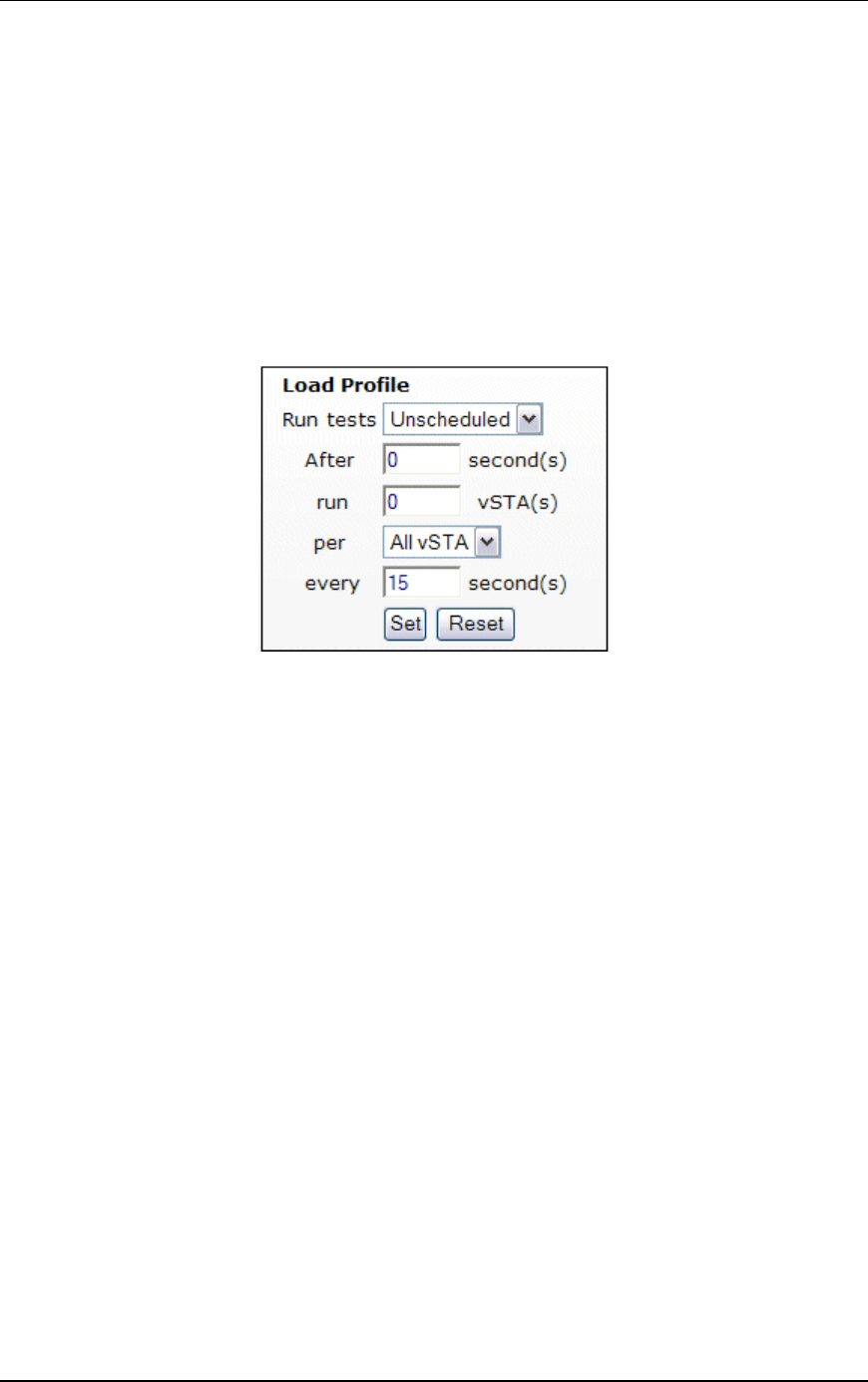
Communication Machinery Corporation (CMC)
5-22 Rev #/Date: 2.0.0 Beta/07.17.03
Using Load Profiles
Load Profiles allow you to control the execution of virtual stations:
Unscheduled or Scheduled. In Unscheduled mode, virtual stations
can be manually controlled. In Scheduled mode, virtual stations
can be run incrementally based on groups (all virtual stations
within the group) or by individual virtual stations.
NOTE: In order to use Scheduled mode, you must disable “Batch
EE Requests” in EmulationEngine configuration (See EE-
>Configure EE). When requests are batched for transmission to
the EmulationEngine, they will not be sent at the scheduled
interval defined by the Load Profile.
Run tests: Select Unscheduled or Scheduled. The default is
Unscheduled. If Scheduled is selected, the Load Profile is in effect
for the scenario. If Unscheduled is selected, the Load Profile is not
in effect.
After: This field defines an initial delay before a run starts:
0...3600 seconds (1 hour). It is the number of seconds after a Run
command has been issued (e.g., the Run button is selected in the
toolbar) that the Load Profile will begin executing.
run: Enter the number of virtual stations to start each time
interval of the load profile. The time interval is specified in the
“every” field.
per: This field defines what scheduling is based on (All vSTA = all
virtual stations, Groups = virtual stations within each group). If
"All vSTA" is selected, the Load Profile will run the next “run”
number of virtual stations at each scheduled iteration. If Group is
selected, the Load Profile will run the next “run” number of virtual
stations from each group at each scheduled iteration. The
scheduled iteration is defined in the “every” field.
every: This field defines the number of seconds between each
repetition of the Load Profile: 1...3600 seconds (1 hour). When this
time expires, the next set of virtual stations (as defined in the run
field) will be executed.
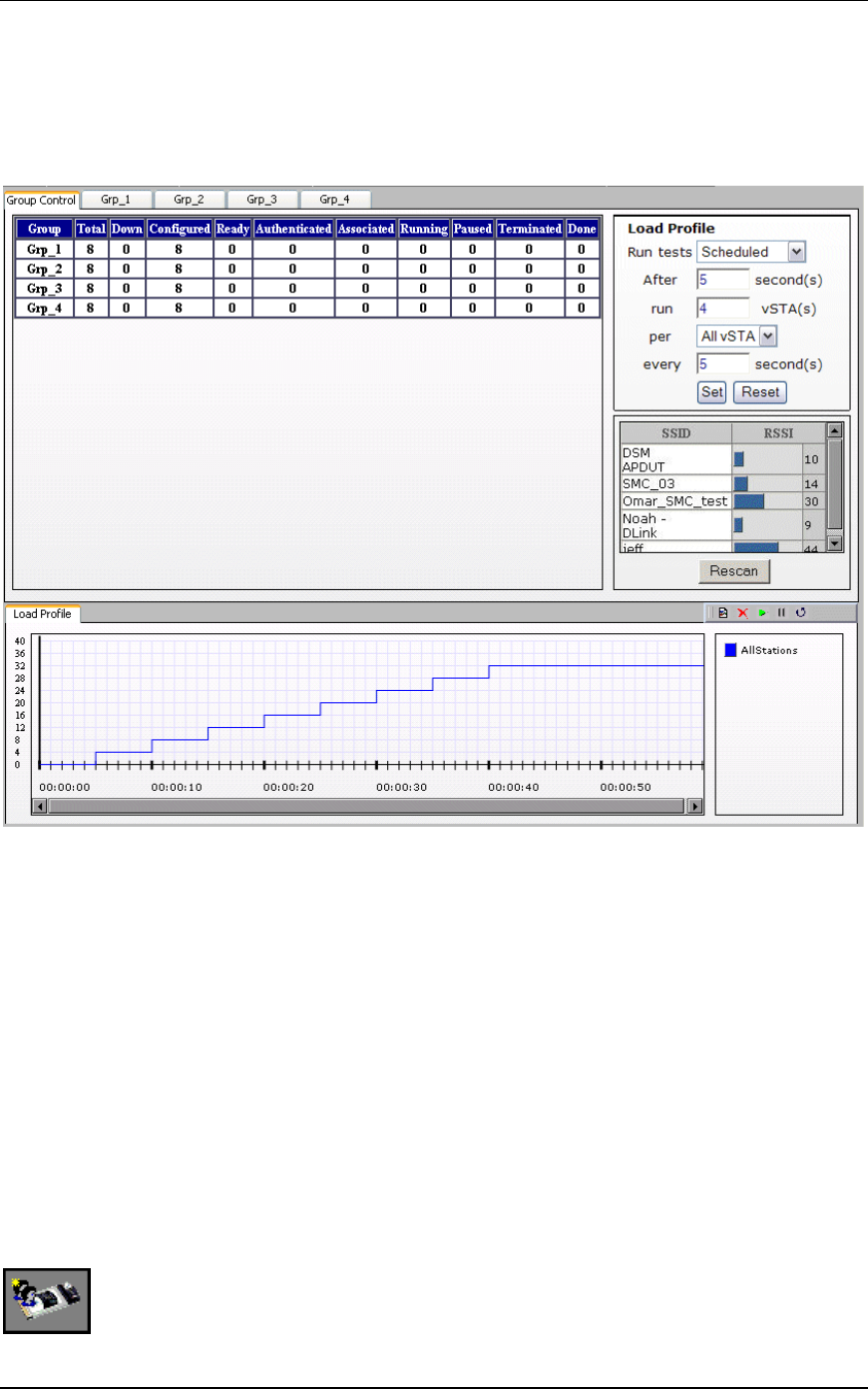
EmulationEngine 11a/b/g User's Guide
Rev #/Date: 2.0.0 Beta/07.17.03 5-23
Select the Load Profile tab in the Load Profile/Monitors section of
the page to show the Load Profile graph. The Load Profile graph
displays the Load Profile setup: x-Axis = time, y-Axis = Groups or
All vSTA depending on the selection in the per field. The following
illustration shows an example Load Profile setup and graph:
After a delay of five seconds, the user interface will instruct the
EmulationEngine to run four virtual stations. Every five seconds
thereafter, the user interface will instruct the EmulationEngine to
run another four virtual stations until all virtual stations have
been executed. The graph depicts this scheduling scheme.
vSTA Side Bar
In the web-based user interface you can create scenarios that
consist of one or more groups of virtual stations. The group
configuration defines a test sequence that the EmulationEngine
will activate to exercise the System Under Test. Virtual stations
can be configured individually or by group. In internal mode, you
can configure each virtual station and/or group to generate traffic
to the system being tested. You can also configure virtual stations
to operate in external mode where an external load generator will
generate the traffic.
New Group: Select this button in the vSTA side bar to define a
new group in a scenario.

Communication Machinery Corporation (CMC)
5-24 Rev #/Date: 2.0.0 Beta/07.17.03
Edit Group: Select this button in the vSTA side bar to modify the
definition of a group.
Delete Group: Select this button in the vSTA side bar to remove
a group and all of its virtual stations from a scenario.
Add vSTA to Group: Select this button in the vSTA side bar to
define a new virtual station in a scenario group.
vSTA->New Group
The New Group dialog is used to define new groups of virtual
stations in a scenario. It is a tabbed dialog with the following
sections: vSTA, Traffic, Runtime, On Error, and Encryption.
vSTA->New Group->vSTA
The vSTA section of the New Emulation Group dialog defines the
range of IP and MAC addresses to be used by virtual stations. The
range of MAC addresses specified in this dialog must be within the
range of MAC addresses defined by the WLAN Base MAC Address
and WLAN MAC Mask in EmulationEngine configuration (see EE-
>Configure EE).

EmulationEngine 11a/b/g User's Guide
Rev #/Date: 2.0.0 Beta/07.17.03 5-25
Group Name: Use a group name that helps you identify the devices
that will be tested (e.g., Warehouse, Stock_Room, Control_Tour,
Shop_Floor, etc.). It can be up to 12 characters (a...z, 0..9, and
underscore (_)).
EE Address: This field shows the IP address of the EmulationEngine
that will run this scenario/test.
Number of Virtual Stations: Enter the number of virtual stations
(0...64) to be created in this scenario group. The default value is 5.
If you specify zero virtual stations in this dialog, you must use the
Add vSTA to Group dialog to add one or more virtual stations to
this group. The Add vSTA to Group dialog will use the default
parameters you set in this group definition.

Communication Machinery Corporation (CMC)
5-26 Rev #/Date: 2.0.0 Beta/07.17.03
Starting IP Address: Enter the starting IP address to be used for
virtual station IP address generation of newly created virtual
stations in this group. Successive virtual station IP addresses will
be sequentially or randomly generated from this base address.
Netmask: This field shows the network mask to be used by virtual
stations in this group. It is not settable here. It is global for all
virtual stations and is an EmulationEngine configuration
parameter.
Ending IP Address: Enter the ending IP address to be used by
virtual stations in this group when generating random addresses
within a range.
Address Generation: Select the Sequential or Random radio button
to instruct the EmulationEngine to sequentially or randomly
assign IP addresses to newly created virtual stations.
Starting MAC Address: Enter the starting MAC address to be used
for virtual station MAC address generation of newly created virtual
stations in this group. Successive virtual station MAC addresses
will be sequentially or randomly generated from this base address.
The starting MAC address must be within the range of MAC
addresses defined by the WLAN Base MAC Address and WLAN
MAC Mask in EmulationEngine configuration (see EE->Configure
EE).
WLAN MAC Mask: The WLAN MAC Mask is a display-only field. It is
defined in EmulationEngine configuration (see EE->Configure EE).
It limits the range of MAC addresses that can be detected on the
wireless LAN and received by the EmulationEngine. For example,
if the WLAN MAC is set to 00:0b:cd:59:23:44 and the mask is set
to ff:ff:ff:ff:00:00, the only MAC addresses that can be detected on
the wireless LAN and received by the EmulationEngine are:
00:0b:cd:59:00:00 - 00:0b:cd:59:ff:ff. All other MAC addresses will
be filtered out.
Ending MAC Address: Enter the ending MAC address to be used by
virtual stations in this group.
Address Generation: Select the Sequential or Random radio button
to instruct the EmulationEngine to sequentially or randomly
assign MAC addresses to newly created virtual stations.
Click “Create” to create the group.
Click “Cancel” to exit this dialog.
vSTA->New Group->Traffic
The Traffic section of the New Emulation Group dialog defines the
type of traffic (Internal/Ping or External/Load Generator) to be
used by the virtual station(s).

EmulationEngine 11a/b/g User's Guide
Rev #/Date: 2.0.0 Beta/07.17.03 5-27
Traffic Source: Select Internal or External from the list box. In
Internal mode, traffic is generated internally by each vSTA using
ICMP Echo (Ping) Request/Reply packets. In External mode,
packets coming into the EmulationEngine over 802.3 are mapped
to virtual stations by source IP address and forwarded via 802.11.
Packets coming back via 802.11 are remapped to the originating
MAC address.
Traffic Type: This selection is only applicable if the Traffic Source is
set to Internal. In this release, only ICMP Echo (Ping) is supported.
Target IP Address: Enter the target IP address where ICMP Echo
(Ping) Requests should be sent.

Communication Machinery Corporation (CMC)
5-28 Rev #/Date: 2.0.0 Beta/07.17.03
Packet Length: Specify the size of the ping data buffer (64...1024).
The default is 1024.
Count: Specify the total number of pings to be sent: 0...10000
(0=None).
Click “Create” to create the group.
Click “Cancel” to exit this dialog.
vSTA->New Group->Runtime
The Runtime section of the New Emulation Group dialog allows
you to run a virtual station’s test multiple times. This is only
applicable to internal traffic generation. After each iteration of a
test, the state of the virtual station can be set to a “base state”. A
user-defined delay between successive iterations is defined in
milliseconds. Optionally, any results collected for the virtual
station can be cleared at the start of each iteration.
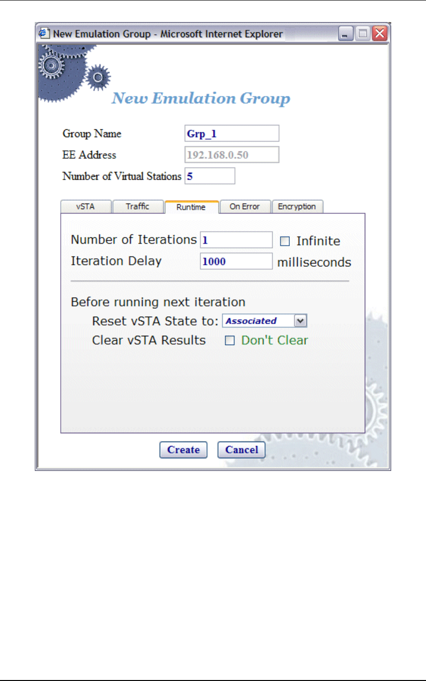
EmulationEngine 11a/b/g User's Guide
Rev #/Date: 2.0.0 Beta/07.17.03 5-29
Number of Iterations: Enter the number of times (1...10000) to
repeat the virtual station’s task (Ping) or select the Infinite
checkbox to continuously iterate indefinitely.
Iteration Delay: Enter the delay (in milliseconds) to be introduced
between iterations of the test. It can be set to a value in the range:
0...300000 milliseconds (5 minutes).
Before Running Next Iteration->Reset vSTA State to: Select a state
from the list box. Each virtual station in this group will be reset to
the selected state (initialized, authenticated, or associated) at the
end of each iteration.
Before Running Next Iteration->Clear vSTA Results: Select this check
box to clear test results before successive iterations of the test.
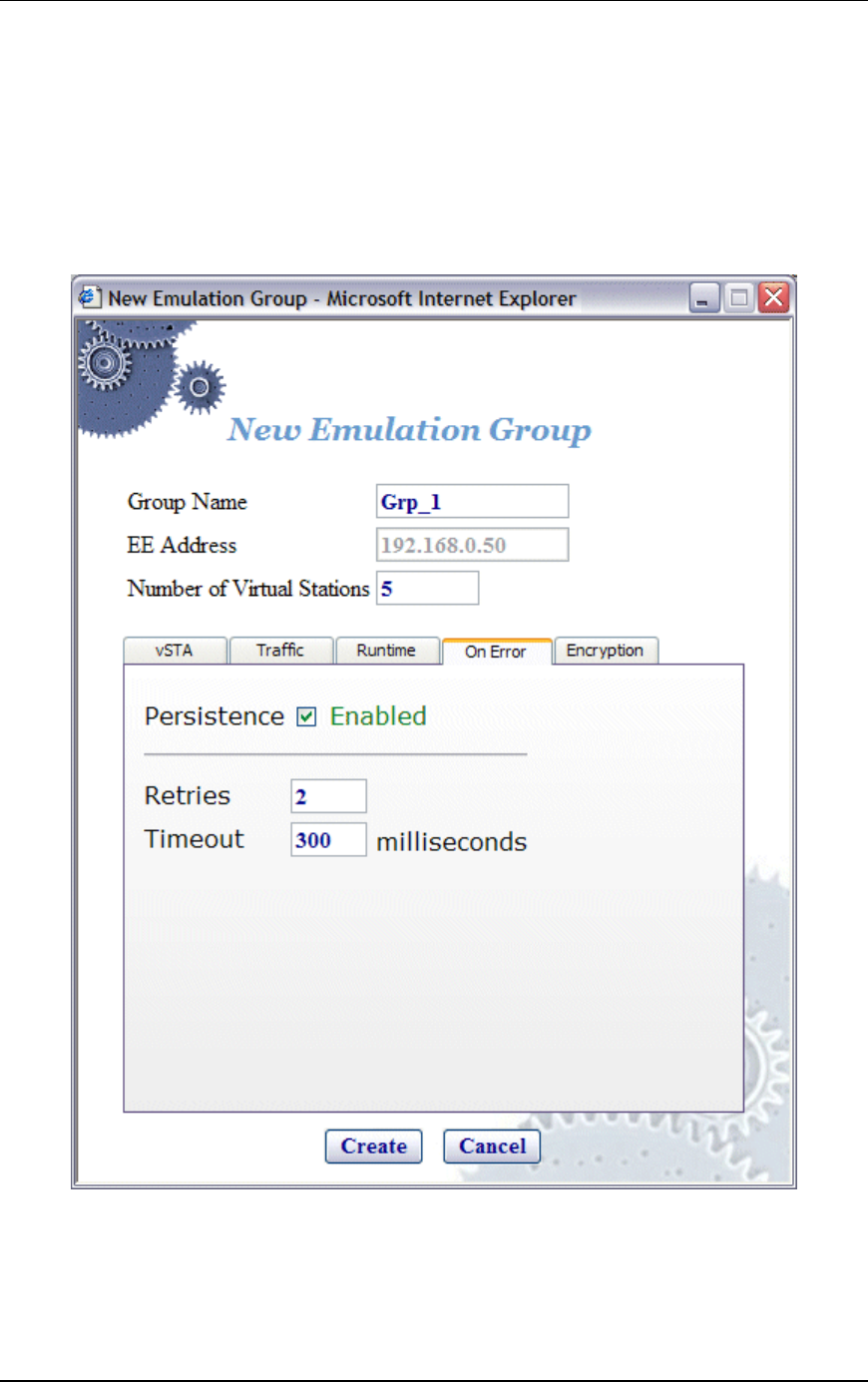
Communication Machinery Corporation (CMC)
5-30 Rev #/Date: 2.0.0 Beta/07.17.03
Click “Create” to create the group.
Click “Cancel” to close this dialog.
vSTA->New Group->On Error
The On Error section of the New Emulation Group dialog defines
whether virtual stations should reconnect to the System Under
Test during a test if the system deauthenticates or disassociates a
virtual station.
Persistence: Select this checkbox to enable or disable persistent
mode. When enabled, the virtual stations in this group will remain
persistent (connected) to a system during a test if the system
deauthenticates or disassociates the virtual station. If the
EmulationEngine loses connection to a System Under Test, it

EmulationEngine 11a/b/g User's Guide
Rev #/Date: 2.0.0 Beta/07.17.03 5-31
must be able to recover and continue the test at the point where it
was interrupted. For example, if a virtual station is in a run or
associated state and an 802.11 management frame (deauth or
disassoc) is sent from the system and received by the
EmulationEngine, this virtual station will attempt to go back to
the state it was in prior to receiving the management frame. If the
virtual station was running a ping test when interrupted, the
virtual station’s ping test will continue. If it was in an associated
state, the virtual station will simply reissue the associate request.
Retries: This field specifies the number of times the
EmulationEngine should issue authentication and association
requests before failing the operation. It can be a value in the range
0...10.
Timeout: This field specifies the timeout value (in milliseconds) for
authentication and association requests. It can be set to a value in
the range 250...60000 milliseconds (1 minute).
Click “Create” to create the group.
Click “Cancel” to close this dialog.
vSTA->New Group->Encryption
This section of the New Group dialog defines whether the virtual
station will use encryption, the associated cipher to be used and
the type of authentication (Open System or Shared Key) to be used
for authenticating with the System Under Test.
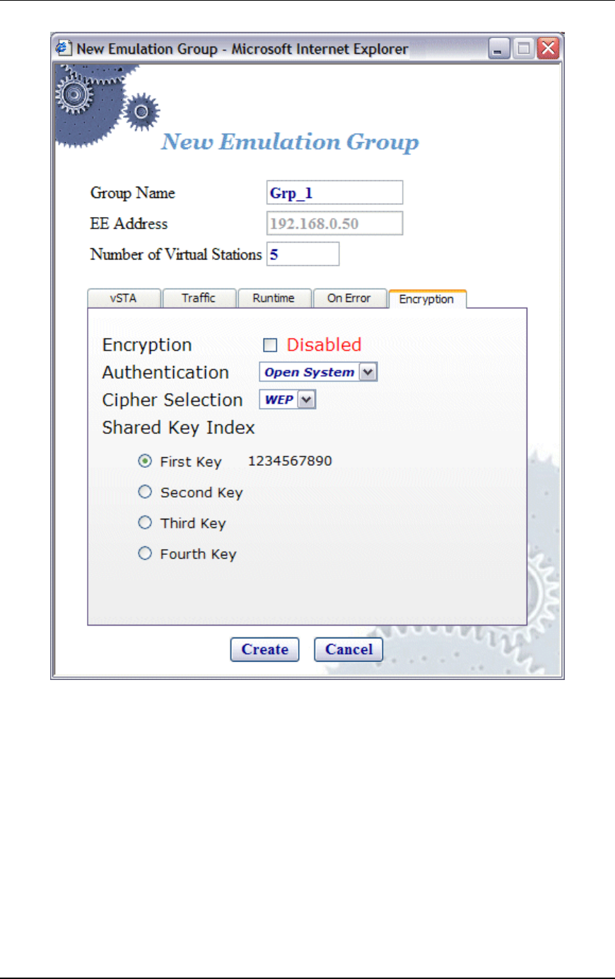
Communication Machinery Corporation (CMC)
5-32 Rev #/Date: 2.0.0 Beta/07.17.03
NOTE: The four shared keys for Wired Equivalency Privacy (WEP)
encryption must be defined in the Encryption Defaults dialog in
the Configuration side bar.
Encryption: Select this checkbox to enable/disable encryption.
Authentication: Select the authentication type: Open System or
Shared Key.
Cipher Selection: Reserved for future use. WEP is the only
supported selection in this release.
Shared Key Index: This section of the dialog will show the shared
keys that were defined in the Encryption Default dialog. See
"Configuration->Encryption". Select the shared key to be used.
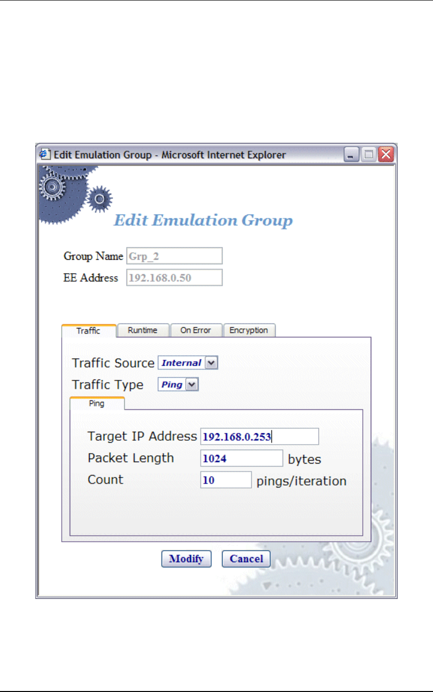
EmulationEngine 11a/b/g User's Guide
Rev #/Date: 2.0.0 Beta/07.17.03 5-33
These keys will be used for encryption by virtual stations in this
scenario group with the System Under Test.
Click “Create” to create the group.
Click “Cancel” to close this dialog.
vSTA->Edit Group
The following dialog is displayed when the Edit Group button is
selected in the vSTA side bar.
This dialog is the same as "vSTA->New Group" dialog except it
does not have a vSTA tab. After virtual stations have been
assigned MAC and IP Addresses, they cannot be changed. See
"vSTA->New Group" for a description of the fields in this dialog.
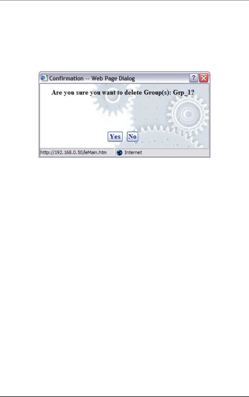
Communication Machinery Corporation (CMC)
5-34 Rev #/Date: 2.0.0 Beta/07.17.03
Click “Modify” to modify all virtual stations with the new settings.
Click “Cancel” to close this dialog without modifying any virtual
stations.
vSTA->Delete Group
When the Delete Group button is selected from the vSTA side bar,
a confirmation dialog will ask you to confirm this selection.
Click “Yes” to remove the group and all virtual stations in it from
the system.
Click “No” to close this dialog without removing the group.
vSTA->Add New vSTA to Group
The following dialog is shown when the Add New vSTA to Group
button is selected in the vSTA side bar.
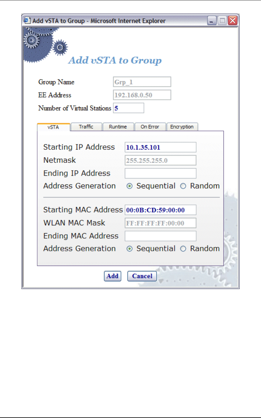
EmulationEngine 11a/b/g User's Guide
Rev #/Date: 2.0.0 Beta/07.17.03 5-35
This dialog is used to add new virtual stations to an existing
scenario group. All fields in this dialog default to the values that
have were initially entered when the group was created. Any
changes to this form will also update these group default values.
See "vSTA->New Group" for a description of the fields in this
dialog.
Click “Add” to add the virtual station.
Click “Cancel” to close this dialog.

Communication Machinery Corporation (CMC)
5-36 Rev #/Date: 2.0.0 Beta/07.17.03
EE (EmulationEngine) Side Bar
The buttons in the EE side bar are used to configure and manage
the EmulationEngine and to select and join with a System Under
Test.
Select SUT: Click this button in the EE side bar to display the
Select System Under Test dialog.
Join SUT: Click this button in the EE side bar to join with the
System Under Test.
Configure EE: Click this button in the EE side bar to configure
the EmulationEngine.
Reconnect EE: Click this button in the EE side bar to reconnect
to the EmulationEngine. This is used after a reboot of the
EmuationEngine.
Reset EE: Click this button in the EE side bar to reset all
statistics counters to zero and all virtual stations to a configured
state.
Reboot EE: Click this button in the EE side bar to reboot the
EmulationEngine.
EE->Select SUT
When the Select SUT button is selected in the EE side bar, the
Select System Under Test dialog is displayed:

EmulationEngine 11a/b/g User's Guide
Rev #/Date: 2.0.0 Beta/07.17.03 5-37
Wireless Mode: This field shows the EmulationEngine’s current
wireless mode (11a, 11b, or 11g). You can select a different
wireless mode from the list box. The web-based user interface will
issue a command to the EmulationEngine to change its wireless
mode and scan for compatible systems. The results of the new
scan will be reflected in the BSSIDs in the list box.
Click on a BSSID in the list box.
Select “Join” to join with the selected System Under Test.
Select “Rescan” to update the list of BSSIDs. This selection will
cause the EmulationEngine to scan for Basic Service Set IDs and
update the list of available systems.
Click “Cancel” to close this dialog without selecting a System
Under Test.
If a scenario with virtual stations already exists and you have
previously joined with a system, the following dialog will be
displayed if you select a different BSSID in the Select System
Under Test dialog:
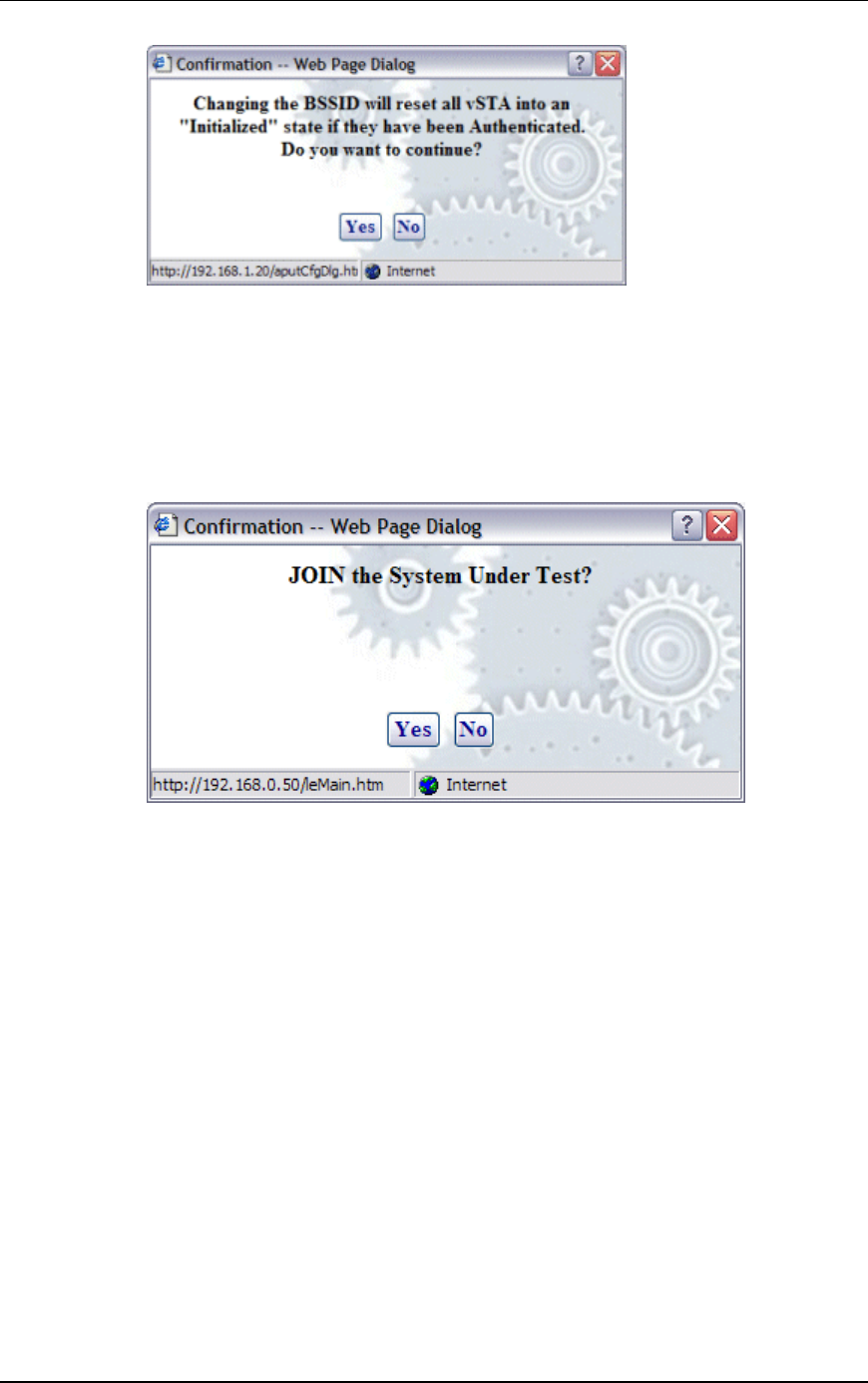
Communication Machinery Corporation (CMC)
5-38 Rev #/Date: 2.0.0 Beta/07.17.03
Click “Yes” to continue and join with a different System Under
Test.
Click “No” to return to the Select System Under Test dialog.
EE->Join SUT
When the Join SUT button is selected in the EE side bar, a
confirmation dialog is displayed:
Click “Yes” to join with the System Under Test.
Click “No” to cancel this operation.
EE->Configure EE
When the Configure EE button is selected in the EE side bar, the
Configure EmulationEngine dialog is displayed:
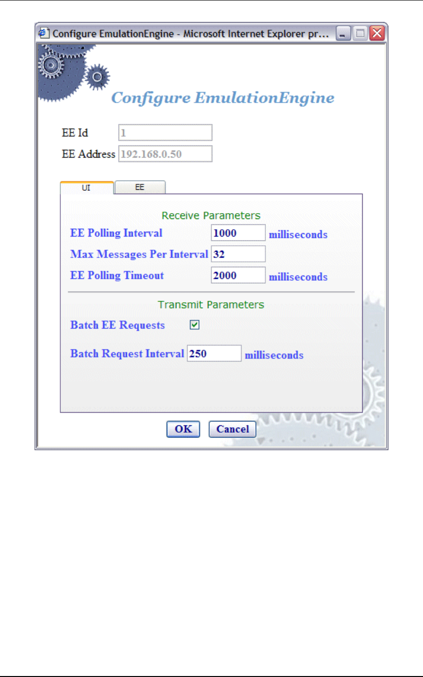
EmulationEngine 11a/b/g User's Guide
Rev #/Date: 2.0.0 Beta/07.17.03 5-39
EE Id: This field is set by the system and cannot be changed.
EE Address: This field shows the EmulationEngine's IP address.
Receive Parameters
EE Polling Interval: This entry defines the interval (in milliseconds)
that the Command PC will poll the EmulationEngine for command
and control messages from the virtual stations. It can be set to a
value in the range: 250...60000 milliseconds (1 minute). If this
time expires without an expected response from the
EmulationEngine, the user interface will display "Busy" next to the
EmulationEngine icon in the toolbar. The "Busy" message
indicates that the EmulationEngine is not responding to the user
interface. Under normal conditions, the "Busy" message may
appear periodically for short periods of time. If the “Busy” message
appears frequently, you may want to increase the value assigned

Communication Machinery Corporation (CMC)
5-40 Rev #/Date: 2.0.0 Beta/07.17.03
to the EE Polling Interval. Also see Chapter 9,
Troubleshooting/EmulationEngine Busy or Not Responding.
Max Messages Per Interval: Specify the maximum number of
messages to be sent in each poll: 1...128.
EE Polling Timeout: This entry defines the time (in milliseconds)
that the Command PC will wait for a response from the
EmulationEngine. It can be set to a value in the range:
500...120000 milliseconds (2 minutes). The recommended value is
two times the EE Polling Interval value. If this time expires without
an expected response from the EmulationEngine, the user
interface will display a dialog indicating that the EmulationEngine
is not responding. When you dismiss the dialog, the status of the
EmulationEngine/System Under Test connection in the toolbar
will display “Offline”. If this dialog and “Offline” status appears
frequently, a larger value should be assigned to the EE Polling
Timeout. Also see Chapter 9, Troubleshooting/EmulationEngine
Busy or Not Responding.
NOTE: Also see the Monitor Update Interval and Monitor Update
Timeout in Monitors->Config Monitors for the interval and update
timeout values that are used by the command PC to collect
statistics values.
Transmit Parameters
Batch EE Requests: This checkbox enables/disables batching of
request messages to be sent to the EmulationEngine. When virtual
stations are running in an iterative fashion or you issue
commands to many virtual stations, this will produce a large
number of requests to the web server on the EmulationEngine.
Request batching will maintain a number of these requests over a
period of time (defined by the Batch Request Interval) and then
issue one large request with all pending instructions.
NOTE: If you are currently running or intend to run a Load Profile,
do not enable Batch EE Requests.
Batch Request Interval: If "Batch EE Requests" is checked/enabled,
specify the interval at which the web-based user interface will
collect (batch) requests and send them to the EmulationEngine. It
can be set to a value in the range: 250...60000 milliseconds (1
minute).
Select the EE tab to define the EmulationEngine's IP address and
network mask.
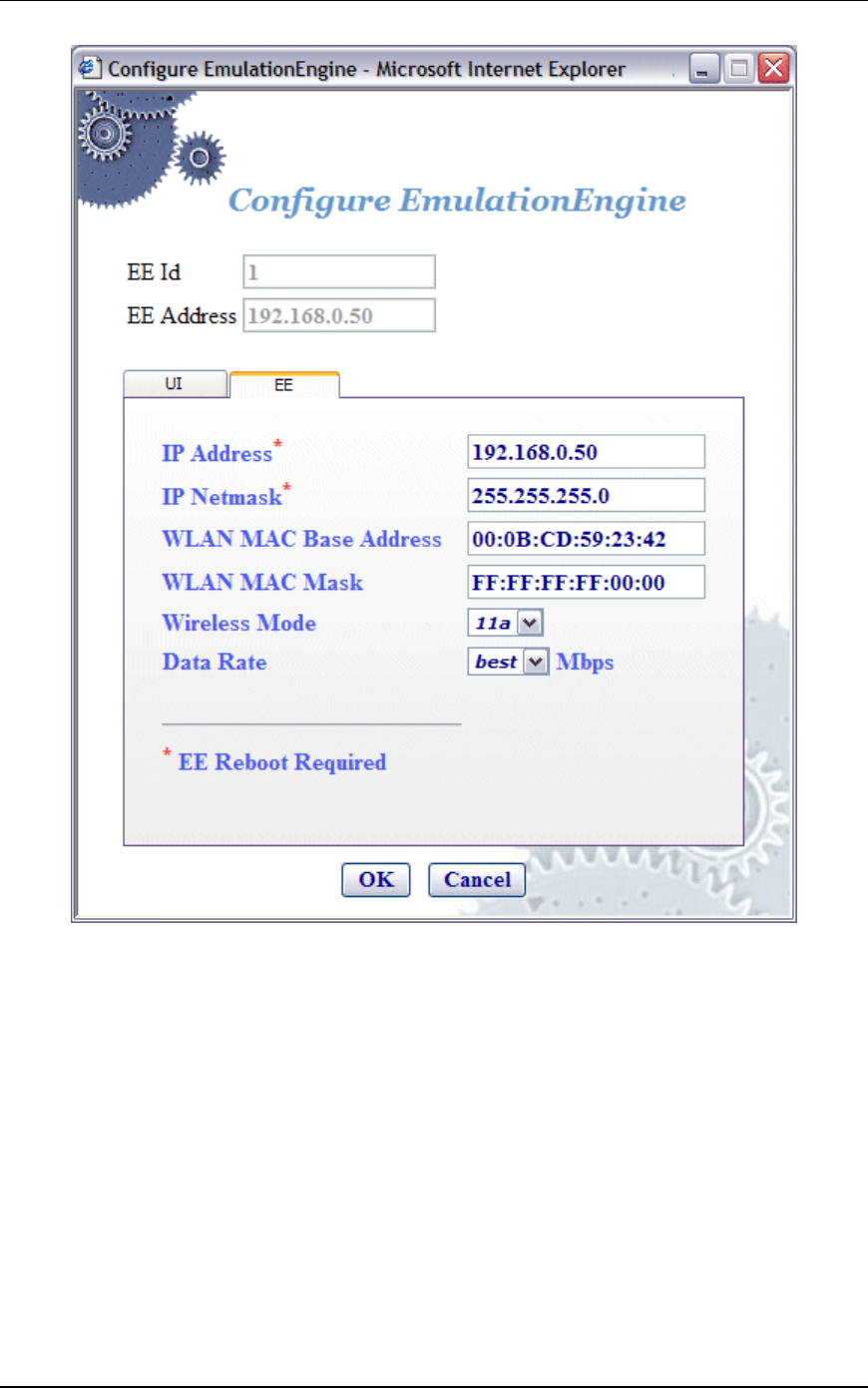
EmulationEngine 11a/b/g User's Guide
Rev #/Date: 2.0.0 Beta/07.17.03 5-41
If you change the IP Address or IP Netmask, a reboot of the
EmulationEngine is required for these changes to take effect.
EE Id: This field is set by the system and cannot be changed.
EE Address: This field shows the EmulationEngine's current IP
address.
IP Address: Enter the EmulationEngine's new IP address. Use a dot
IP address (e.g., 192.168.0.50).
IP Netmask: Enter the EmulationEngine's network mask. The
network mask of the EmulationEngine must match the IP subnet
addressing scheme for internal mode testing (it is not used for
external mode). For example, if the EmulationEngine's IP address
is 10.1.40.18 and the system being tested is 10.1.35.17, then the
subnet mask is 16 bits or 255.255.0.0.

Communication Machinery Corporation (CMC)
5-42 Rev #/Date: 2.0.0 Beta/07.17.03
NOTE: If you change the IP Address of the EmulationEngine and
reboot, the web client does not automatically change its
EmulationEngine IP address. You will need to do it manually. If
you forget, you will need to restart the web browser after the
EmulationEngine has rebooted. However, you can also double-
click on the engine address in the toolbar->status bar to display a
dialog that will let you change the address without restarting.
WLAN MAC Base Address: The Wireless LAN MAC address defaults
to a specific address (typically in the 00:0b:cd:xx:xx:xx
range). It is a globally unique MAC address that is programmed in
to the EmulationEngine hardware. The address can be changed to
any non-broadcast or non-multicast valid MAC address. If you use
multiple EmulationEngine's at your facility, each should have a
WLAN MAC whose prefix is unique. For example, on the first
EmulationEngine , use WLAN MAC Address: 04:0d:e0:62:23:57
and on the second EmulationEngine, use WLAN MAC
Address: 06:0f:14:62:32:a0.
WLAN MAC Mask: This address is used in conjunction with the
WLAN Base MAC Address for configuration of virtual stations. If
for example, the WLAN MAC is set to 00:0b:cd:59:23:44 and the
mask is set to ff:ff:ff:ff:00:00, the only MAC addresses that can be
detected on WLAN and received by the EmulationEngine are:
00:0b:cd:59:00:00 - 00:0b:cd:59:ff:ff. All other MAC addresses will
be filtered out. The mask limits the range of MAC addresses that
are assigned to virtual stations. The mask that is specified here
will be displayed in the WLAN MAC Mask field when the vSTA tab
is selected in the New Emulation Group dialog (See vSTA->New
Group->vSTA).
Wireless Mode: Select a wireless mode (11a, 11b, or 11g) from the
list box. The items that are available in this list box will be
different depending on the feature set that you ordered from CMC.
The wireless mode also affects the types of devices the
EmulationEngine can discover during a scan operation. See the
General Usage Notes in Chapter 1.
Data Rate: Select a data rate from the list box. The rates that are
available in this list box will be different depending on the Wireless
Mode selection.
Click “OK” to save this configuration.
Click “Cancel” to close this dialog.
EE->Reconnect EE
Reconnect is required after reboot or if you become disconnected
from the EmulationEngine for any reason. When the Reconnect
EE button is selected in the EE side bar, a confirmation dialog is
displayed:
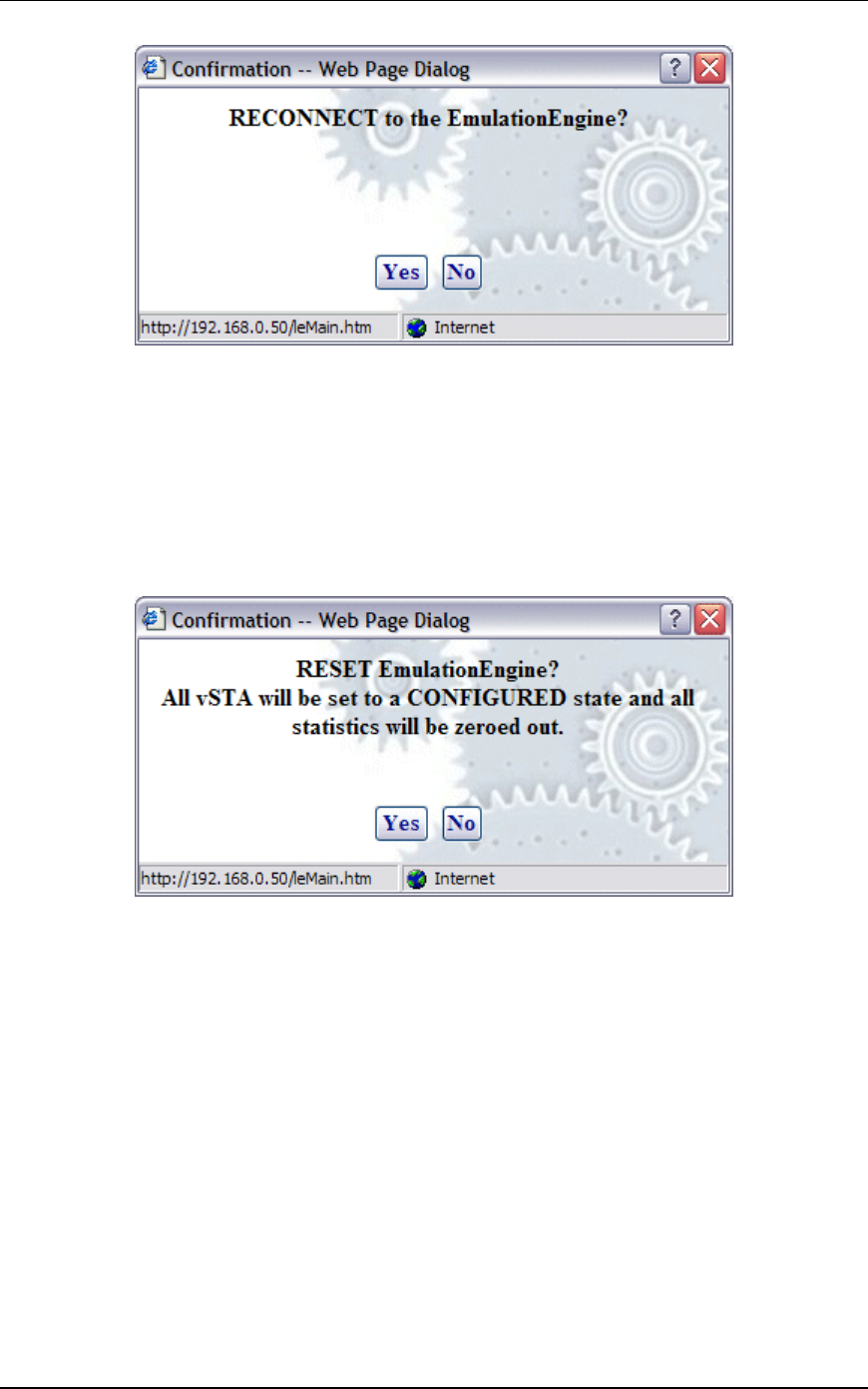
EmulationEngine 11a/b/g User's Guide
Rev #/Date: 2.0.0 Beta/07.17.03 5-43
Click “OK” to reconnect to the EmulationEngine.
Click “No” to cancel the reconnect selection.
Following successful reconnect, the web-based user interface will
restore the scenario (if any) in the EmulationEngine.
EE->Reset EE
When the Reset EE button is selected in the EE side bar, a
confirmation dialog is displayed:
Click “Yes” to reset all virtual stations to a configured state and to
reset all statistics counters to zero.
Click “No” to cancel the reset selection.
EE->Reboot EE
When the Reboot EE button is selected in the EE side bar, a
confirmation dialog is displayed:
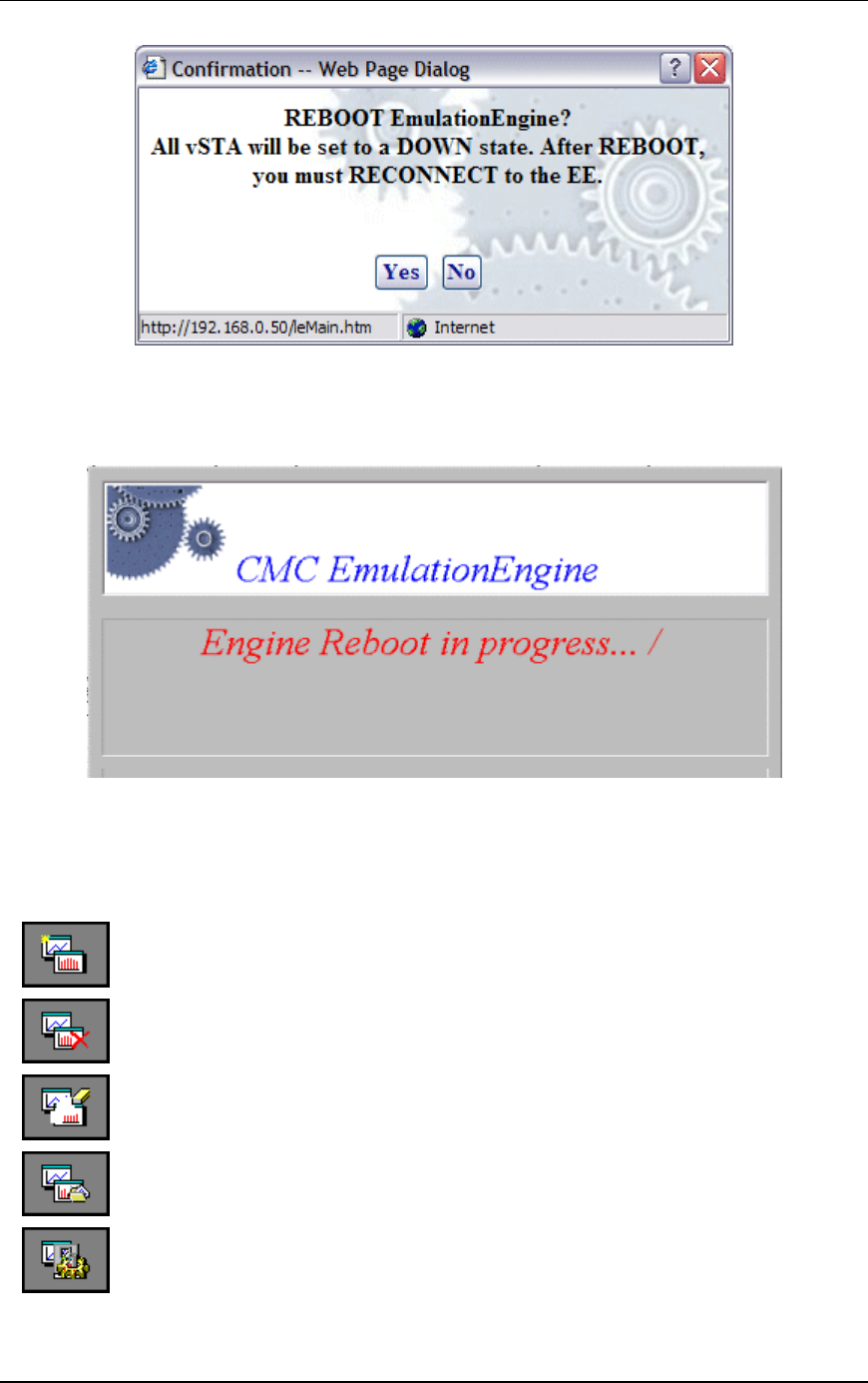
Communication Machinery Corporation (CMC)
5-44 Rev #/Date: 2.0.0 Beta/07.17.03
Click “Yes” to reboot the EmulationEngine.
Click “No” to cancel the reboot operation.
When Yes is selected, the following dialog is displayed:
Monitors Side Bar
The Monitors side bar is used to define, delete, clear, export, and
configure monitors. After a monitor is defined using New Monitor,
the bottom section of the main page will show statistics counters.
New Monitor: Select this button to define a new monitor. You can
define up to four different monitors in each scenario.
Delete Monitor: Select this button to delete the currently
displayed monitor.
Clear Monitor: Select this button to clear the statistics counters
in the currently displayed monitor.
Export Monitor: Select this button to export the statistics
counters for one or more monitors.
Config Monitors: Select this button to configure how monitors
are maintained and updated with data from the EmulationEngine.

EmulationEngine 11a/b/g User's Guide
Rev #/Date: 2.0.0 Beta/07.17.03 5-45
A monitor is one or more user-selected statistics counters that the
web-based user interface will collect from the EmulationEngine
and display in the user-selected format (i.e., line graph, bar graph
or table). All data collected can be exported. Monitors are based on
Linegraphs, Bargraphs and Tables. You can use these to monitor
the summary statistics of the EmulationEngine or a summary
“Master vSTA” that shows virtual station statistics across all
virtual stations.
NOTES:
1) Each scenario can include up to four different monitors.
2) Monitor values are stored in memory on the command PC. If
you run one or more monitors for an extended period of time,
available memory may become depleted and this can affect the
performance of the command PC.
Monitors->New Monitor
The New Monitor dialog is a tabbed dialog that can be used to
define predefined, summary, and summary virtual station
counters to be maintained during the execution of a test.
Monitors->New Monitor->Predefined
Use the Predefined section of the Define New Monitor dialog to
select predefined statistics counters.
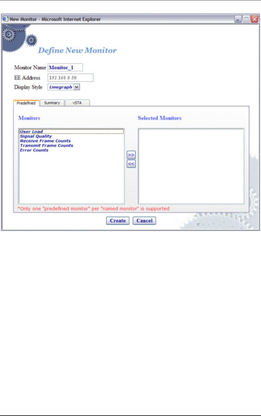
Communication Machinery Corporation (CMC)
5-46 Rev #/Date: 2.0.0 Beta/07.17.03
Monitor Name: Enter a monitor name. It can be up to 12
characters (a...z, 0..9, and underscore (_)).
EE Address: This field shows the EmulationEngine's IP address.
Display Style: Select a display style from the list box. It can be one
of the following: Line Graph, Bar Graph, or Table.
Monitors->Selected Monitors: Select one of the monitors to be
maintained. Use the [>>] button (or double-click the line item) to
transfer the predefined monitor to the Selected Monitors column.
See "Chapter 8, Statistics Counters" for a description of each of
these statistics counters.
Click “Create” to create and display the monitor.
Click “Cancel” to close this dialog.
Monitors->New Monitor->Summary
Use the Summary section of the Define New Monitor dialog to
select summary statistics counters.
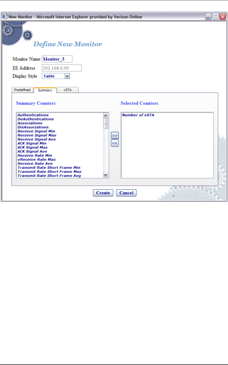
EmulationEngine 11a/b/g User's Guide
Rev #/Date: 2.0.0 Beta/07.17.03 5-47
Summary Counters->Selected Counters: Select one or more of the
counters to be maintained in the test results file. Use the [>>]
button to transfer the counters to the Selected Counters column.
See "Chapter 8, Statistics Counters" for a description of each of
these statistics counters.
Click “Create” to create and display the monitor.
Click “Cancel” to close this dialog.
Monitors->New Monitor->vSTA
Use the vSTA section of the Define New Monitor dialog to select
the master (summary) virtual station statistics counters.
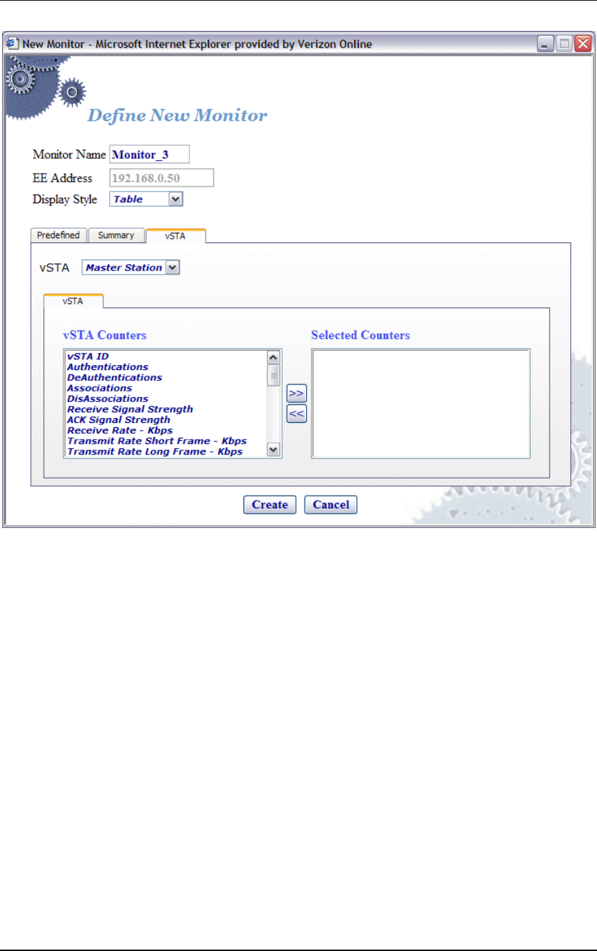
Communication Machinery Corporation (CMC)
5-48 Rev #/Date: 2.0.0 Beta/07.17.03
vSTA (s): Select a virtual station from the list box. The Master
Station is a summary that shows virtual station statistics across
all virtual stations.
vSTA Counters->Selected Counters: Select one or more of the
counters to be maintained in the test results file. Use the [>>]
button to transfer the counters to the Selected Counters column.
See "Chapter 8, Statistics Counters" for a description of each of
these statistics counters.
Click “Create” to create and display the monitor.
Click “Cancel” to close this dialog.
When you select one or more counters and choose the Create
button, the bottom half of the screen will show the current results
in the selected display style. Example:
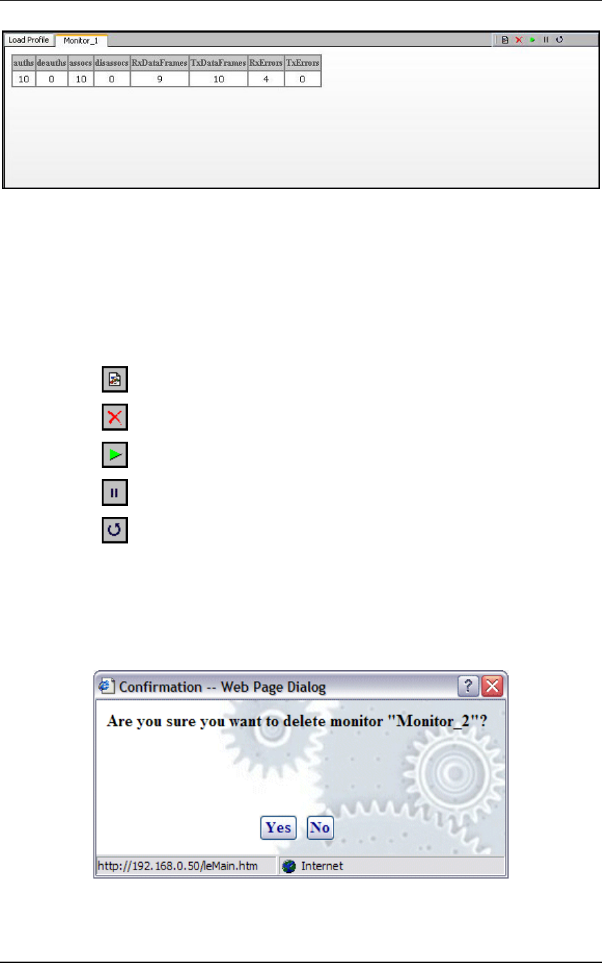
EmulationEngine 11a/b/g User's Guide
Rev #/Date: 2.0.0 Beta/07.17.03 5-49
As you run scenario tests, the monitors will be updated with
current data from the EmulationEngine. For chart display styles,
the legends on the right side of the monitor indicate the statistics
counters selected in the New Monitor dialog. For table display
styles, the table headings indicate the statistics counters selected
in the New Monitor dialog. See "Chapter 8, Statistics Counters"
for a description of each of these statistics counters. The toolbar
buttons on the right-side of the monitor display can be used for
the following functions:
Create a New Monitor
Delete the currently selected monitor.
Run a monitor.
Pause a monitor.
Reset a monitor.
See "Monitor Toolbar Buttons" for more information about these
buttons.
Monitors->Delete Monitor
When the Delete Monitor button is selected in the Monitors side
bar or the monitor toolbar, a confirmation dialog is displayed.
Select “Yes” to delete the current monitor.

Communication Machinery Corporation (CMC)
5-50 Rev #/Date: 2.0.0 Beta/07.17.03
Select “No” to cancel the delete selection.
Monitors->Clear Monitor
When the Clear Monitor button is selected in the Monitors side
bar or the monitor toolbar, a confirmation dialog is displayed.
Select “Yes” to clear the monitor. This will set all counters in the
monitor to zero. Statistics gathered up to this point are not cleared
and are still exportable.
Select “No” to close this dialog without clearing the monitor.
Monitors->Export Monitor
This function is used to export the collected statistics in a defined
monitor. For export, the data obtained from the monitor is saved.
NOTE: For all graphs, each tick saves the information of each field
that is requested. This can grow large depending on how long the
monitor has run. An artificial limit of one hour has been enforced
to clear this saved data. At the end of each hour, this stored data
array is cleared.
When the Export Monitor button is selected in the Monitoring side
bar, the Export Monitor dialog is displayed:
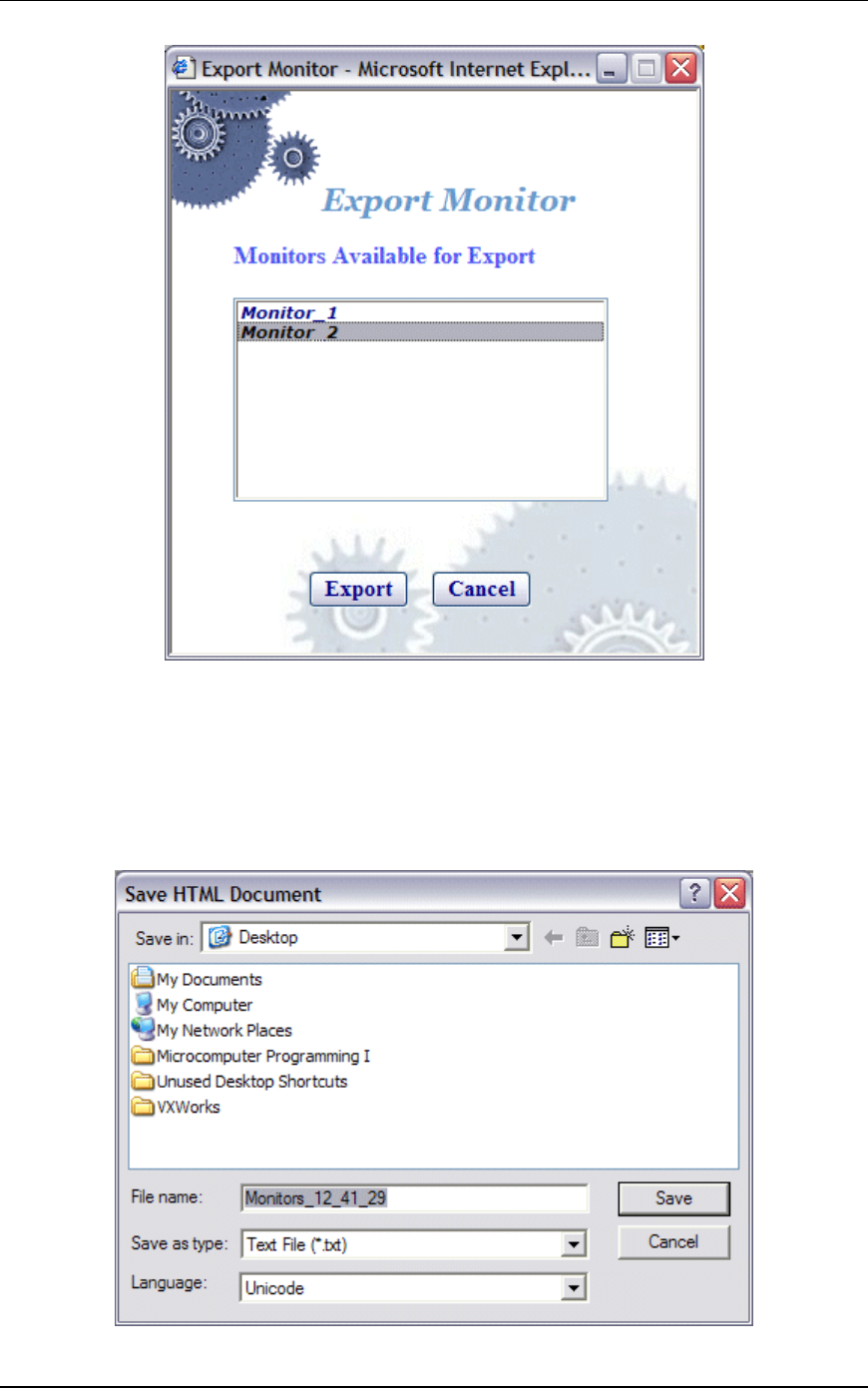
EmulationEngine 11a/b/g User's Guide
Rev #/Date: 2.0.0 Beta/07.17.03 5-51
Select one or more monitors in the list box.
Select “Export” to export the monitors in the Selected Monitors list
box.
Select “Cancel” to close this dialog without exporting monitors.
When the Export button is selected, a Save HTML Document
dialog is displayed:
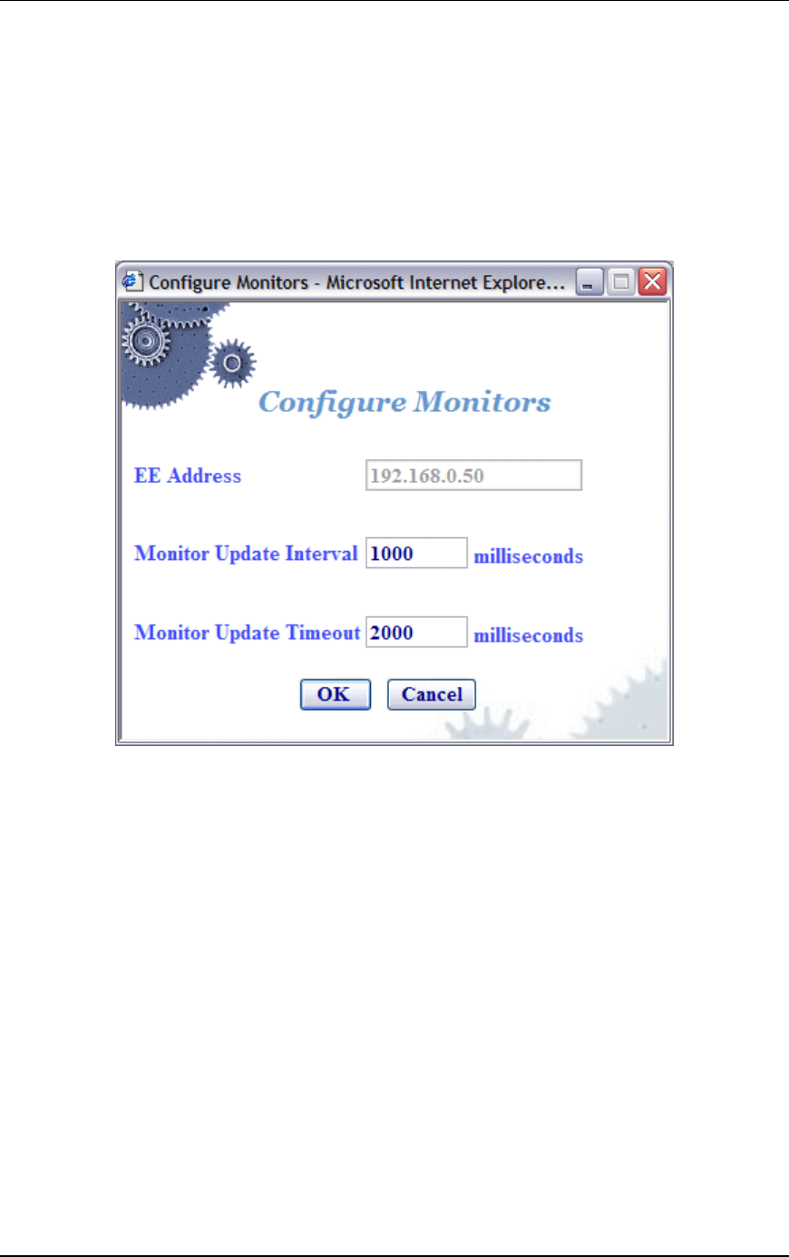
Communication Machinery Corporation (CMC)
5-52 Rev #/Date: 2.0.0 Beta/07.17.03
Identify the name of the file where the monitor information is to be
written.
Select “Save” to save the information in to the specified file.
Select “Cancel” to exit this dialog without exporting any data.
Monitors->Config Monitors
When the Config Monitors button is selected in the Monitors side
bar, the Configure Monitors dialog is displayed.
EE Address: This field shows the IP address of the
EmulationEngine.
Monitor Update Interval: This entry defines the interval (in
milliseconds) that the Command PC will poll the EmulationEngine
for new statistics counters. It can be set to a value in the range:
250...60000 milliseconds (1 minute). Any value under 1000
milliseconds is not advised and may affect performance
significantly. If you notice issues with update performance, try
increasing this value.
Monitor Update Timeout: This entry defines the time (in
milliseconds) that the Command PC will wait for a response from
the EmulationEngine. It can be set to a value in the range:
500...120000 milliseconds (2 minutes). The recommended value is
two times the Monitor Update Interval value. If this time expires
without an expected response from the EmulationEngine, the user
interface will attempt to restart the monitor update timer.
NOTE: Also see the EE Polling Interval and EE Polling Timeout in
EE->Configure EE for the interval and update timeout values that

EmulationEngine 11a/b/g User's Guide
Rev #/Date: 2.0.0 Beta/07.17.03 5-53
are used by the command PC to send command and control
information to the EmulationEngine.
Select “OK” to save this monitor configuration.
Select “Cancel” to close this dialog.
Event Log Side Bar
The buttons in the Event Log side bar are used to display, clear,
export, and configure the Event Log:
Event Log: Select this button to display the last 400 event log
entries.
Clear Log: Select this button to clear the current contents of the
event log.
Export Log: Select this button to export the last 400 event log
entries to a file.
Configure Log: Select this button to configure event logging.
Also see "Chapter 7, Event Logging" for more information about
how the EmulationEngine creates and maintains the event log.
Event Log->Event Log
When the Event Log button is selected in the Event Log side bar,
the last 400 event log entries are displayed. Example:
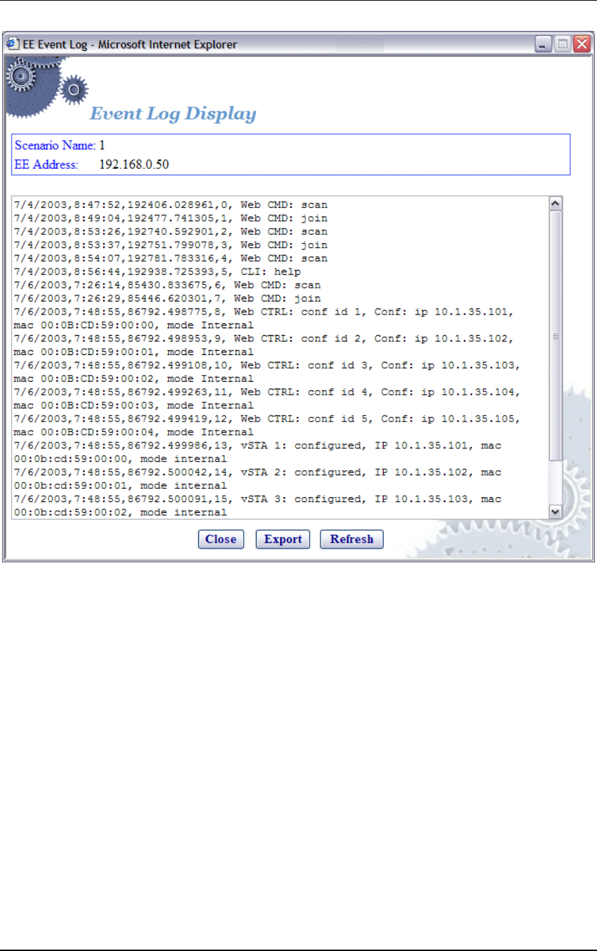
Communication Machinery Corporation (CMC)
5-54 Rev #/Date: 2.0.0 Beta/07.17.03
NOTE: The web-based user interface only displays the last 400
records in the event log.
Select “Close” to close this dialog.
Select “Export” to export this event log information to a file.
Select “Refresh” to update the dialog with new events.
Event Log->Clear Log
When the Clear Log button is selected in the Event Log side bar, a
confirmation dialog will ask you to confirm this selection.
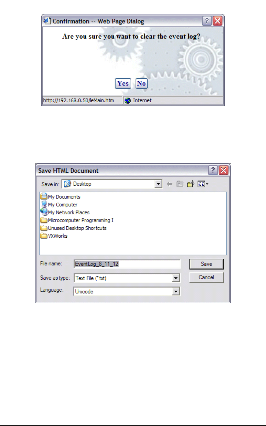
EmulationEngine 11a/b/g User's Guide
Rev #/Date: 2.0.0 Beta/07.17.03 5-55
Select “Yes” to clear the event log.
Select “No” to exit this dialog without clearing the event log.
Event Log->Export Log
When the Export Log button is selected in the Event Log side bar,
a Save HTML Document dialog is displayed.
Identify the name of the file where the log is to be written.
Select “Save” to save the event log in a file.
Select “Cancel” to exit this dialog.
Event Log->Configure Log
When the Configure Log button is selected in the Event Log side
bar, the Event Log Configuration dialog is displayed.
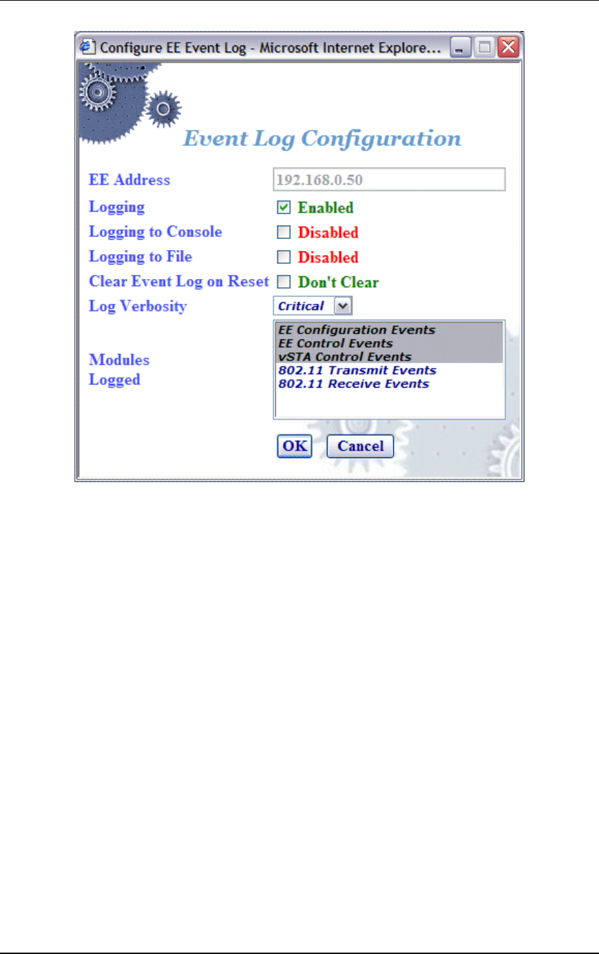
Communication Machinery Corporation (CMC)
5-56 Rev #/Date: 2.0.0 Beta/07.17.03
EE Address: This field defines the IP address of the
EmulationEngine where the log file resides.
Logging: Enable/disable event logging.
Logging to Console: Enable/disable event logging to the CLI console
buffer.
Logging to File: Enable/disable event logging to a file in the
EmulationEngine's flash file system.
Clear Event Log on Reset: This checkbox enables/disable clearing of
the event log when the scenario is reset.
Log Verbosity: The verbosity level sets thresholds for which events
are to be logged: at higher verbosity more events are logged; at
lower verbosity, fewer events are logged. Select Critical, Low,
Medium, or High from the list box.
Modules Logged: Select one or more modules (system processes)
that event messages of the selected level should be collected from.
Select “OK” to close this dialog and save the event log
configuration.
Select “Cancel” to close this dialog without saving event log
configuration.
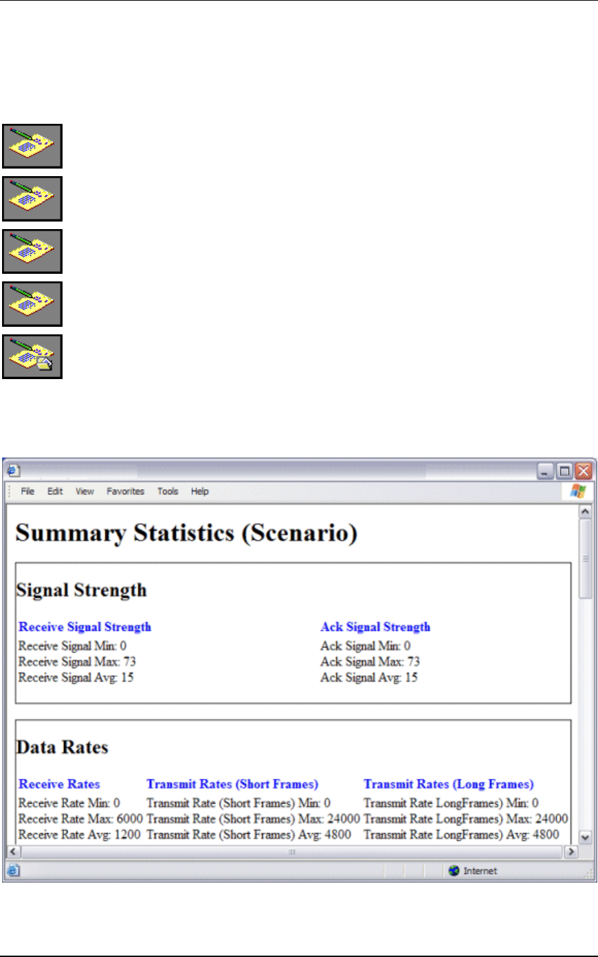
EmulationEngine 11a/b/g User's Guide
Rev #/Date: 2.0.0 Beta/07.17.03 5-57
Reports Side Bar
The options in the Reports side bar can be used to display
statistics counters that are maintained by the EmulationEngine
during the execution of a test.
Scenario Summary: Select this button to display summary
statistics of the EmulationEngine and all virtual stations.
Group Summary: Select this button to display summary
statistics of a scenario group.
vSTA Master: Select this button to display statistics collected for
all virtual stations.
vSTA Detailed: Select this button to display detailed statistics
counters for each virtual station.
Export Reports: Select this button to export/view reports in a
CSV (Comma-Separated-Values) file format.
Reports->Scenario Summary
The following statistics report is displayed when the Scenario
Summary button is selected in the Reports side bar.
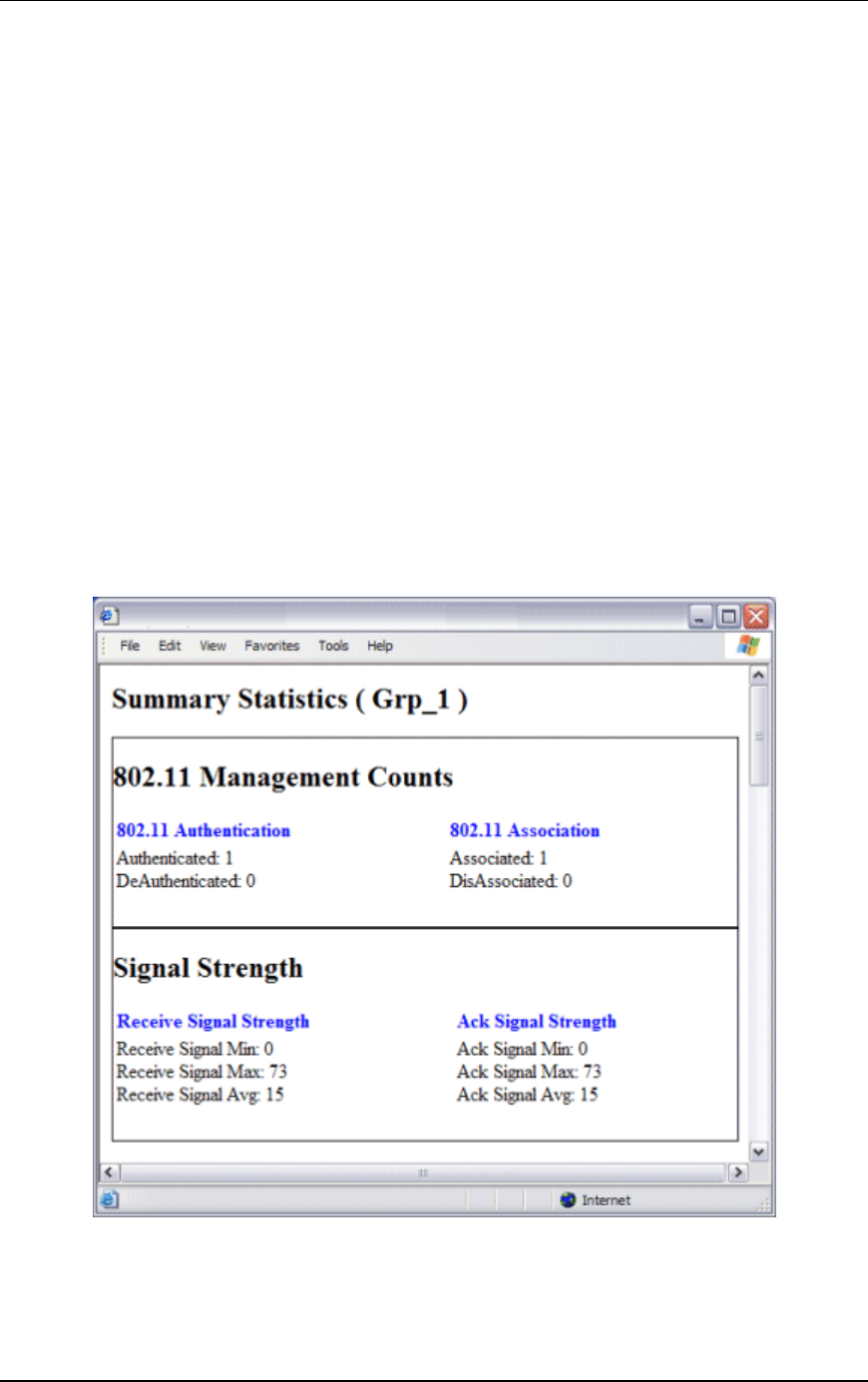
Communication Machinery Corporation (CMC)
5-58 Rev #/Date: 2.0.0 Beta/07.17.03
Summary statistics provide a summary report taken over a set of
virtual stations. The virtual station set can be a defined group or
all virtual stations currently in the system. In contrast, the
individual virtual station statistics report provides a list of
statistics and counters for all virtual stations. The summary
report provides a summary of the statistics and counters taken
over the indicated set of virtual stations. The summary gives, for
each counter, the minimum and maximum values for that counter
found in the set of virtual stations examined, the average value,
and where applicable the total (sum) over the set of virtual
stations. The Avg fields (i.e., Receive Rate Avg, Transmit Rate
(Short Frame) Avg, and Transmit Rate (Long Frame) Avg) in the
Data Rate section of the summary statistics display is the average
rate for the master vSTA since the time the EmulationEngine
joined to a System Under Test. See "Chapter 8, Statistics
Counters" for a description of statistics counters that may be
displayed in this report.
Reports->Group Summary
The following statistics report is displayed when the Group
Summary button is selected in the Reports side bar.
See "Chapter 8, Statistics Counters" for a description of statistics
counters that may be displayed in this report.
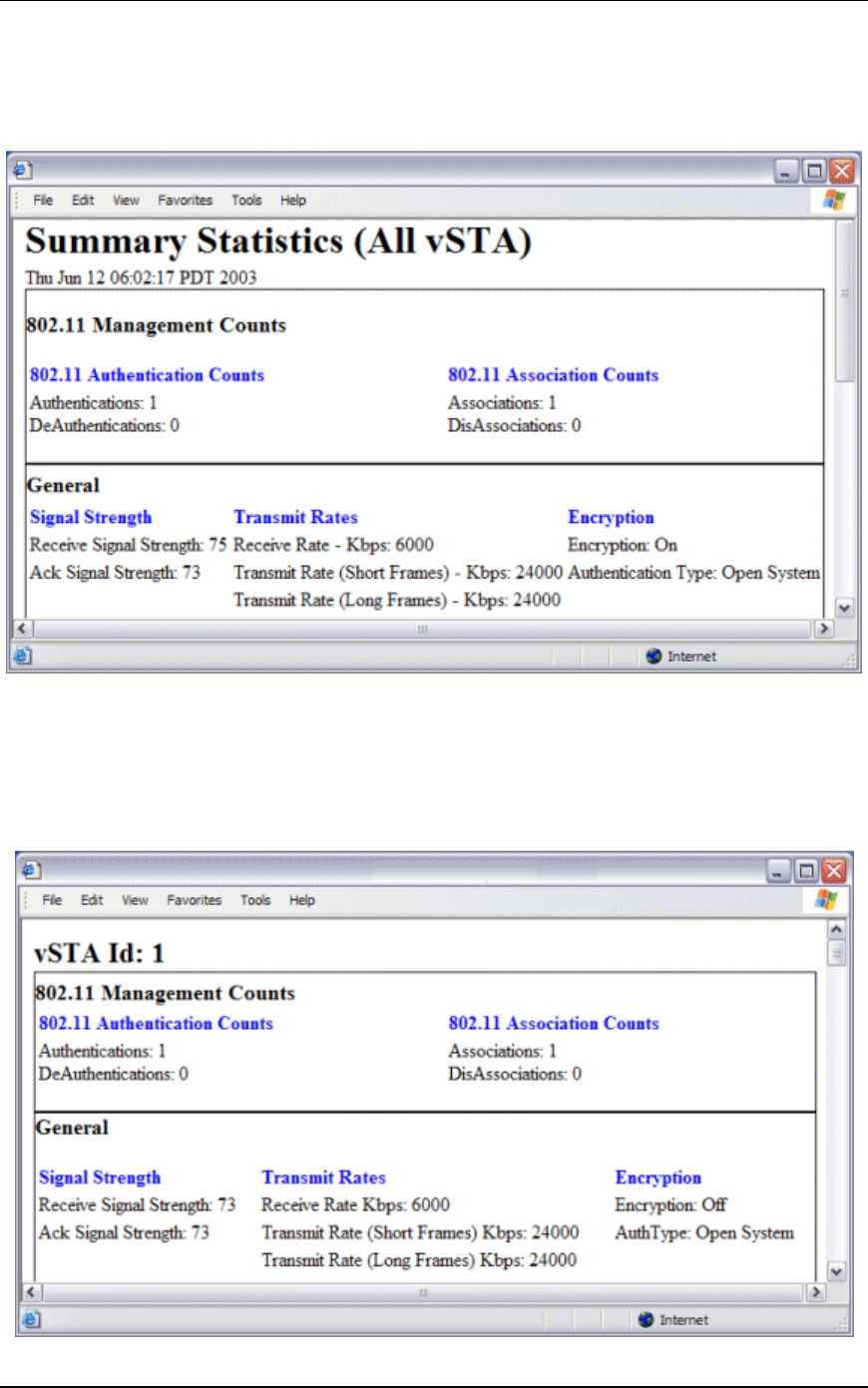
EmulationEngine 11a/b/g User's Guide
Rev #/Date: 2.0.0 Beta/07.17.03 5-59
Reports->vSTA Master
The following statistics report is displayed when the vSTA Master
button is selected in the Reports side bar.
See "Chapter 8, Statistics Counters" for a description of statistics
counters that may be displayed in this report.
Reports->vSTA Detail
The following statistics report is displayed when the vSTA Detail
button is selected in the Reports side bar.
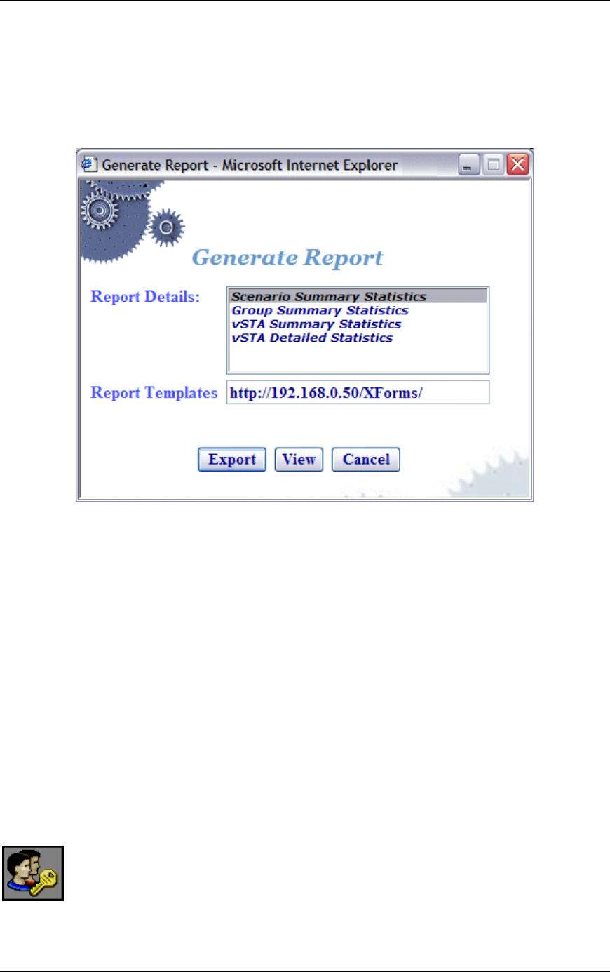
Communication Machinery Corporation (CMC)
5-60 Rev #/Date: 2.0.0 Beta/07.17.03
See "Chapter 8, Statistics Counters" for a description of statistics
counters that may be displayed in this report.
Reports->Export Reports
When the Export Reports button is selected in the Reports side
bar, the Generate Report dialog is displayed:
Report Details: Select one or more reports to export in the Report
Details list box.
Report Templates: Defines the directory/path where XML transform
files are retrieved. These XSLT files are then used to create reports
from the XML data returned by the EmulationEngine. By
specifying another directory path, you can customize reports to
suit your needs.
Select “Export” to export the report(s) to a comma-separated
values (.CSV) file.
Select “View” to display the selected report(s).
Select “Cancel” to exit this dialog.
Configuration Side Bar
The buttons in the Configuration side bar are used to define
encryption keys, default ping settings, and the appearance of the
web-based user interface.
Encryption: Select this button to define Encryption keys.
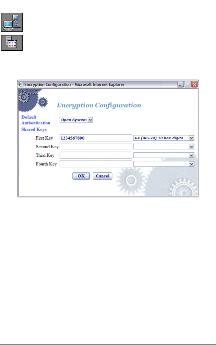
EmulationEngine 11a/b/g User's Guide
Rev #/Date: 2.0.0 Beta/07.17.03 5-61
Ping Defaults: Select this button to define a default ping target,
ping packet length, and number of iteration values.
Preferences: Select this button to configure the appearance of
the user interface.
Configuration->Encryption
When the Encryption button is selected in the Configuration side
bar, the Encryption Configuration dialog is displayed:
This screen is used to define up to four shared keys for Wired
Equivalency Privacy (WEP) encryption. WEP encrypts data using
an RC4 stream cipher (from RSA Security) with a seed of 64, 128
or 152 bits before transmission to the wireless network. Each
shared key can be 64, 128, or 152 bits. If 64 is selected in the list
box, you must enter 10 hex digits. If 128 is selected in the list box,
you must enter 26 hex digits. If 152 is selected in the list box, you
must enter 32 hex digits. These keys will be displayed in the
Encryption section of the New Emulation Group dialog, the Edit
Emulation Group dialog, and the Add vSTA to Group dialog.
NOTE: To delete a key, remove the key from the field.
Click “OK” to save the Encryption keys to the EmulationEngine.
Click “Cancel” to close this dialog without saving this Encryption
configuration.
Configuration->Ping Defaults
When the Ping Defaults button is selected in the Configuration
side bar, the Ping Configuration dialog is displayed. Any changes
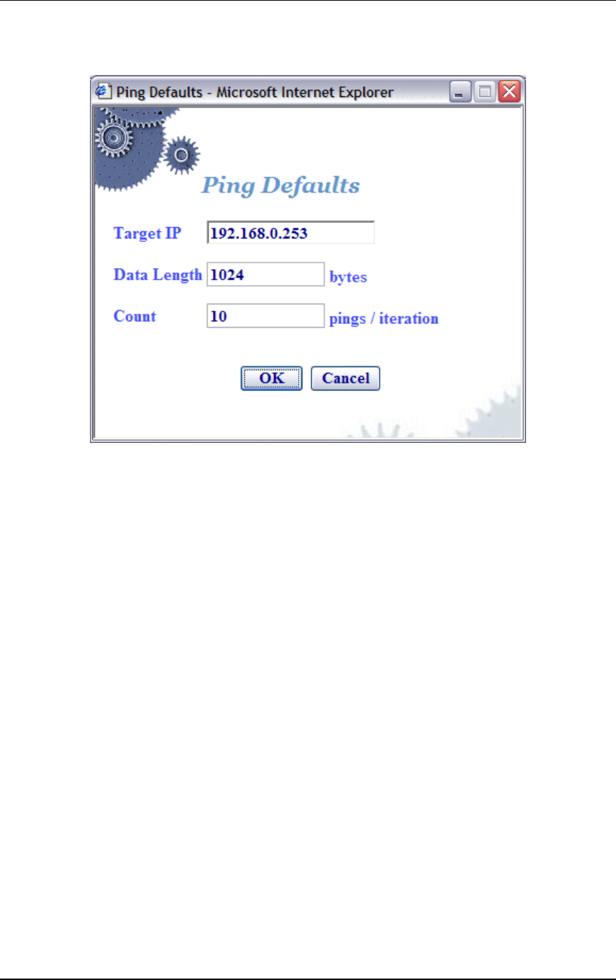
Communication Machinery Corporation (CMC)
5-62 Rev #/Date: 2.0.0 Beta/07.17.03
made in this dialog will affect all future group/virtual station
creation defaults for this session.
Target IP: Enter the target IP address where ICMP Echo (Ping)
Request/Response messages should be sent.
Data Length: Specify the size (64...1024) of each message.
Count: Specify the total number of pings to be sent: 0...10000
(0=None).
Click “OK” to save the default Ping configuration.
Click “Cancel” to close this dialog without saving this
configuration.
Configuration->Preferences
When the Preferences button is selected in the Configuration side
bar, the UI Configuration dialog is displayed.
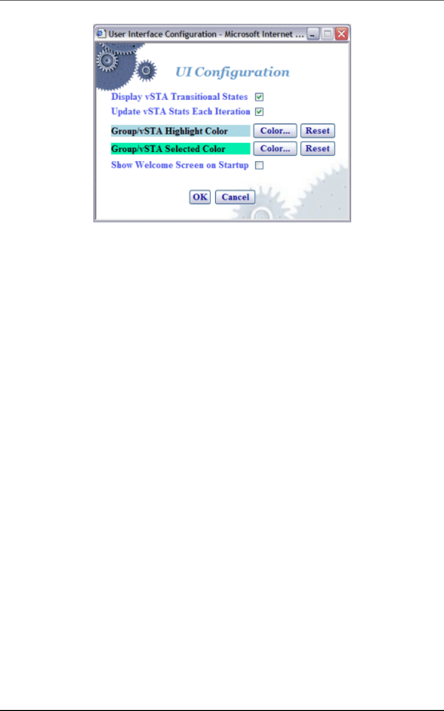
EmulationEngine 11a/b/g User's Guide
Rev #/Date: 2.0.0 Beta/07.17.03 5-63
Display vSTA Transitional States: This checkbox enables/disables
update of the web-based user interface to show changes in virtual
station transitional states such as authenticating, associating, de-
authenticating and disassociating. Deselecting this option will
improve user interface performance.
Update vSTA Stats Each Iteration: Select this checkbox to
enable/disable automatic update of virtual station statistics.
Statistics are gathered by making extra calls to the
EmulationEngine. Under high virtual station load, deselecting this
option will improve user interface performance.
Group/vSTA Highlight Color: Select the Color button to show a color
selector dialog and choose a color to highlight groups and virtual
stations in the group grid. After a color has been chosen, the Reset
button can be used to reset the color to its original state.
Group/vSTA Selected Color: Select the Color button to show a color
selector dialog and choose a color for selected groups and virtual
stations in the group grid. After a color has been chosen, the Reset
button can be used to reset the color to its original state.
Show Welcome Screen on Startup: Select this checkbox to
enable/disable the welcome screen that is shown when you
successfully log in to the web-based user interface.
Select “OK” to close this page and save the configuration.
Select “Cancel” to close this dialog without saving this
configuration.
Menus & Toolbars
The menus and toolbars at the top of the web-based user interface
can be used to run tests, manipulate virtual stations, show
results, and configure the EmulationEngine as well as general
scenario management.
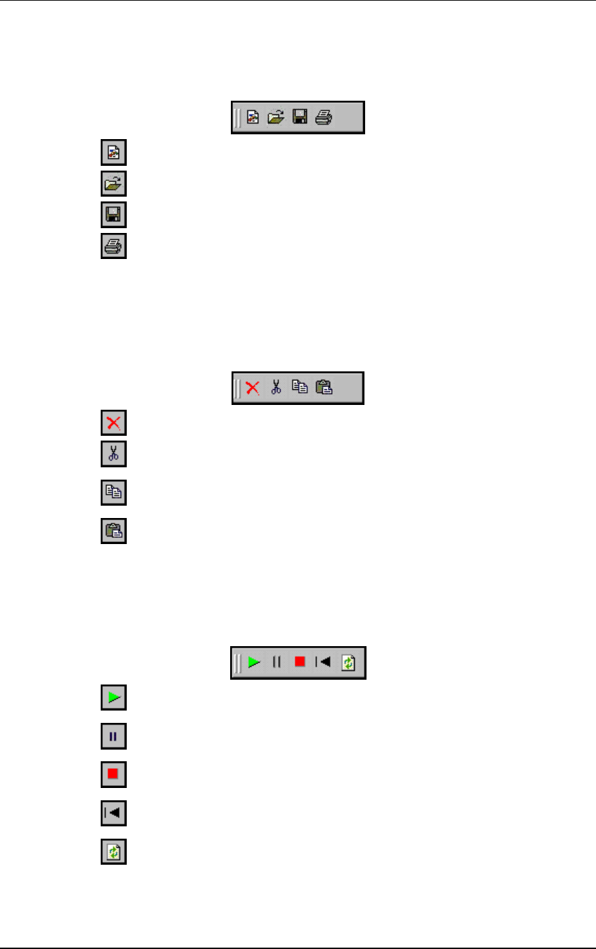
Communication Machinery Corporation (CMC)
5-64 Rev #/Date: 2.0.0 Beta/07.17.03
File Toolbar
The buttons in this toolbar are used to create, open, save and
print scenarios.
New Scenario: Create a new scenario
Open Scenario: Open an existing scenario
Save Scenario: Save the current scenario
Print: Print the scenario configuration
Edit Toolbar
The buttons in this toolbar are used to delete, cut, copy and paste
virtual stations within and between groups. It can also be used to
delete groups when a group is selected in the group control
tab/table.
Delete: Delete currently selected group(s) or virtual station(s)
Cut: Cut the currently selected virtual station(s) and place into an internal
virtual station buffer.
Copy: Copy the selected virtual station(s) into an internal virtual station
buffer.
Paste: Paste the virtual station definition from the internal virtual station
buffer into the currently selected group
Scenario Toolbar
The buttons in this section of the toolbar can be used to run,
pause, stop, restart, or refresh the entire scenario of all virtual
stations.
Run Scenario: Run the test for all groups and all virtual stations in a
scenario
Pause Scenario: Pause the test for all groups and all virtual stations in a
scenario
Terminate Scenario: Stop the test for all groups and all virtual stations in a
scenario
Reset Scenario: Reset the test for all groups and all virtual stations in a
scenario
Refresh Scenario: Refresh the test for all groups and all virtual stations in
a scenario
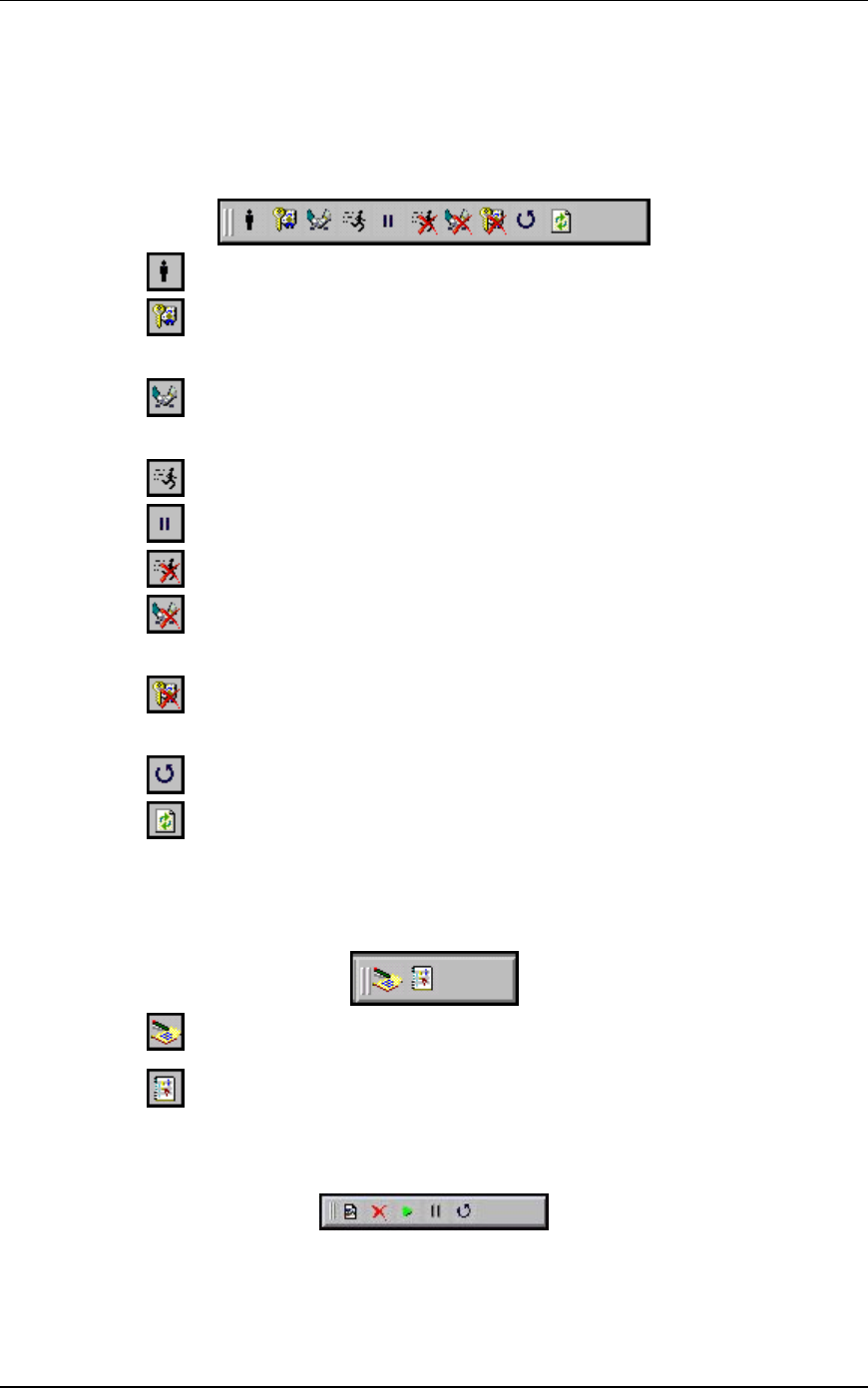
EmulationEngine 11a/b/g User's Guide
Rev #/Date: 2.0.0 Beta/07.17.03 5-65
vSTA Toolbar
The buttons in this toolbar are used to run, pause, stop, restart,
or refresh selected virtual stations or groups of virtual stations.
The selected action will be executed for the group(s) and/or virtual
station(s) that are selected/highlighted in the group control grid.
Initialize: Initialize the currently selected groups or virtual stations
Authenticate: This selection will cause the currently selected virtual
stations or all virtual stations in a group to initiate the authentication
sequence with the System Under Test
Associate: This selection will cause the currently selected virtual stations
or all virtual stations in a group to initiate the association sequence with
the System Under Test
Run: Run a test for selected groups or virtual stations
Pause: Pause a test for selected groups or virtual stations
Stop: Terminate a test for selected groups or virtual stations
Disassociate: This selection will cause the currently selected virtual
stations or all virtual stations in a group to initiate the disassociation
sequence with the System Under Test
Deauthenticate: This selection will cause the currently selected virtual
stations or all virtual stations in a group to initiate the deauthentication
sequence with the System Under Test
Reset: Reset a test for selected groups or virtual stations
Refresh: Refresh a test for selected groups or virtual stations
Reports Toolbar
The buttons in this toolbar are used to view reports and the event
log:
View Reports: This button displays the Generate Report dialog from which
you can select a report to be displayed or exported.
View Event Log: This button displays the last 400 entries in the event log.
Monitor Toolbar
This toolbar is located in the top-right corner of the monitoring
section of the screen. The buttons in this toolbar can be used to
control monitor(s).
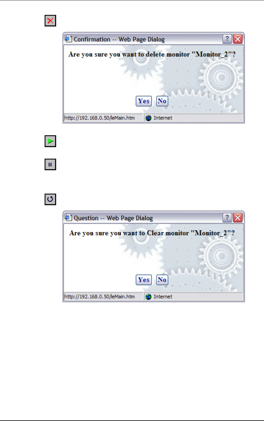
Communication Machinery Corporation (CMC)
5-66 Rev #/Date: 2.0.0 Beta/07.17.03
When the Delete Monitor button is selected in the monitor toolbar, a
confirmation dialog is displayed.
Select Yes to delete the current monitor. Select No to close this dialog.
When the Run Monitor button is selected from the monitor toolbar, the
currently displayed monitor will start gathering and displaying its target
statistics
When the Pause Monitor button is selected from the monitor toolbar, the
currently displayed monitor will stop its target statistics. However,
statistics will still be accumulating in the background and are exportable.
When the Clear Monitor button is selected in the monitor toolbar, a
confirmation dialog is displayed.
Select Yes to clear the current monitor. This will set all counters in the
current monitor to zero. Statistics gathered up to this point are not cleared
and are still exportable. Select No to close this dialog without clearing the
monitor.
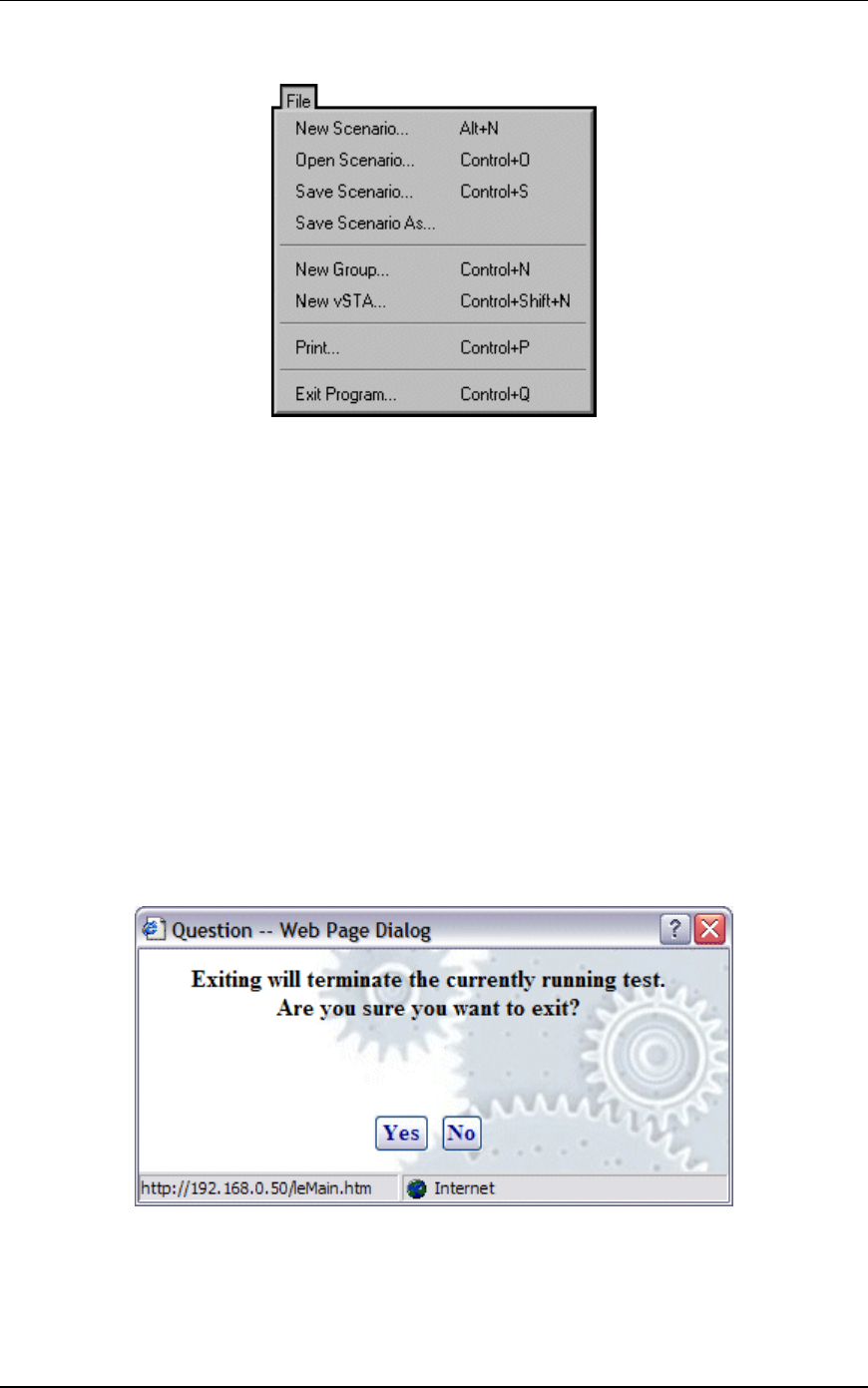
EmulationEngine 11a/b/g User's Guide
Rev #/Date: 2.0.0 Beta/07.17.03 5-67
File Menu
New Scenario...: This selection creates a new scenario in which
groups and virtual stations can be defined.
Open Scenario...: This selection shows the Open Scenario dialog
where you can choose from a list of existing scenario files on the
EmulationEngine or browse your PC for scenario files.
Save Scenario...: This selection will show the Save Scenario dialog.
Save Scenario As...: This selection can be used to save a scenario as
a new instance.
New Group...: This selection will display the New Emulation Group
dialog.
New vSTA...: This selection will display the Add vSTA to Group
dialog.
Print: Send the current scenario configuration to your printer.
Exit Program: Exit the web-based user interface. If a scenario is
currently active/running, the following dialog is displayed:
Click Yes to continue with exit from the web-based user interface.
Click No to return to the currently running test.
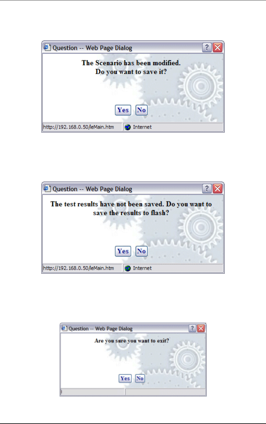
Communication Machinery Corporation (CMC)
5-68 Rev #/Date: 2.0.0 Beta/07.17.03
If the current scenario has been modified during this web-based
user interface session, the following dialog will prompt you to save
these changes.
Click Yes to display the Save Scenario dialog and save the
scenario on your PC or in flash on the EmulationEngine. Click No
if you do not want to save the modified scenario.
If active virtual stations have been configured, a dialog will prompt
you to save the results to flash:
Click Yes to save the results of any active scenario(s) in the
EmulationEngine's flash file system. Click No to discard current
test results.
A dialog will prompt you to confirm exit from the web-based user
interface:
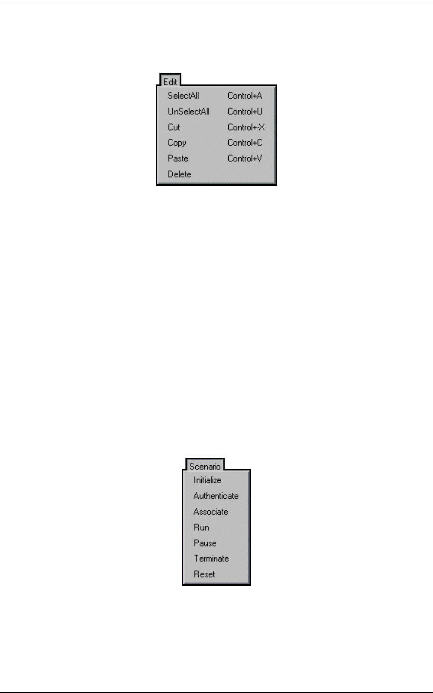
EmulationEngine 11a/b/g User's Guide
Rev #/Date: 2.0.0 Beta/07.17.03 5-69
Click Yes to exit. Click No to return to the web-based user
interface.
Edit Menu
Select All: If a group tab is selected, select all virtual stations in a
scenario group. If the Group Control tab is displayed, select all
groups.
UnSelect All: If a group tab is selected, unselect all virtual stations
in a scenario group. If the Group Control tab is displayed, unselect
all groups.
Cut: Remove the definition of the currently selected virtual station
and put it in the Windows clipboard.
Copy: Copy a virtual station definition to the Windows clipboard.
Paste: Paste the virtual station definition in the Windows clipboard
to the currently selected group.
Delete: If a group tab is selected, delete the currently selected
virtual station. If the Group Control tab is displayed, delete the
currently selected group.
Scenario Menu
After you have defined a scenario, use the Scenario Menu to
initialize and exercise the scenario.
Initialize: Initialize all virtual stations defined in the scenario.
Authenticate: When this option is selected, all virtual stations
defined in a scenario will initiate the authentication sequence to
the System Under Test.
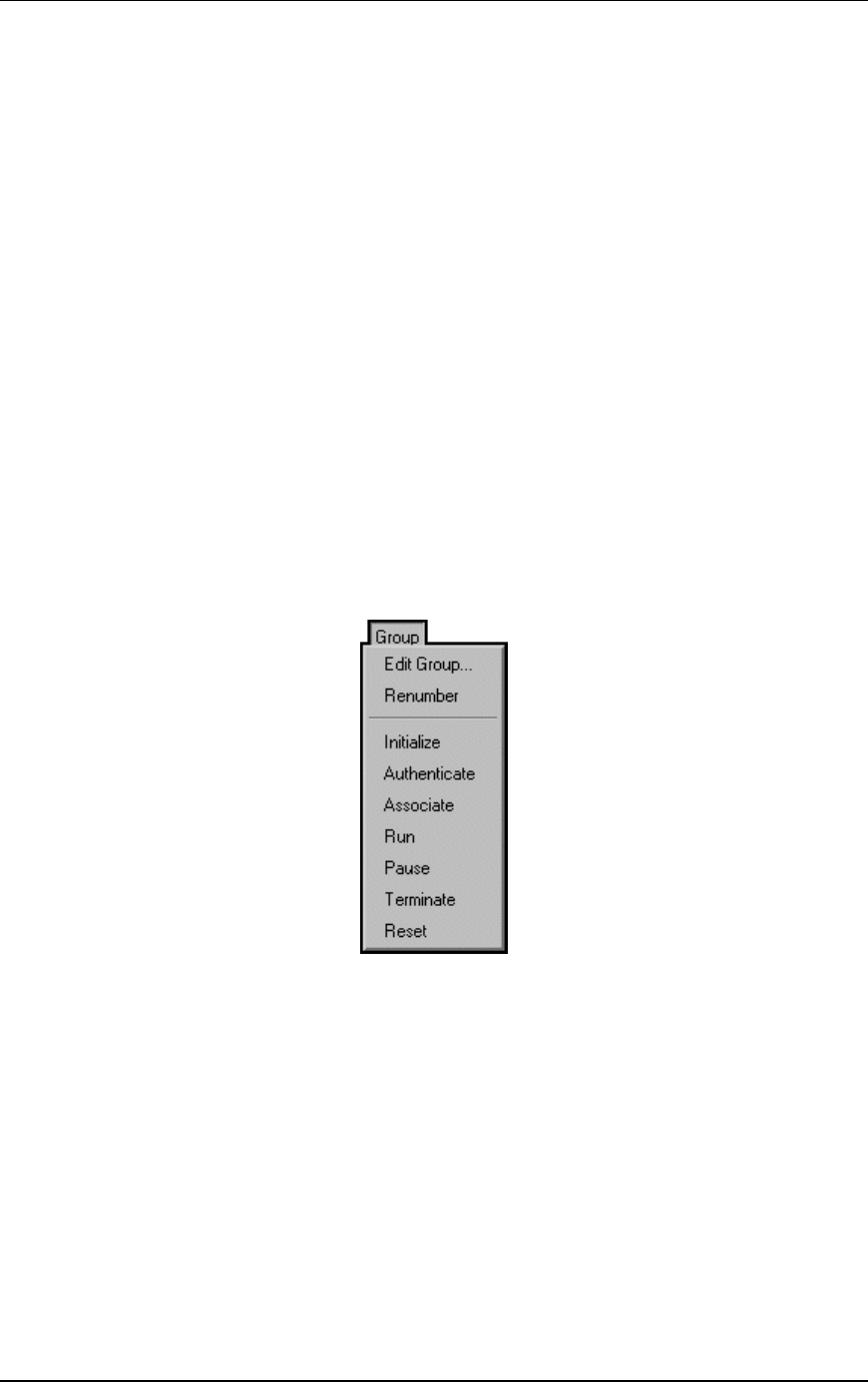
Communication Machinery Corporation (CMC)
5-70 Rev #/Date: 2.0.0 Beta/07.17.03
Associate: When this option is selected, all virtual stations defined
in a scenario will initiate the association sequence to the System
Under Test.
Run: Start execution of the test defined by this scenario.
Pause: Pause the test and temporarily halt all virtual stations
defined in the scenario. Virtual stations may be restarted by
selecting the Run option. This option will be grayed-out (not
selectable) if the scenario is not running.
Terminate: Stop a test and halt all virtual stations defined in the
scenario. Virtual stations must be reset before they can be run
again. This option will be grayed-out (not selectable) if the scenario
is not running.
Reset: Reset all virtual stations in the scenario to an initialized
state. Statistics for the virtual stations are reset to zero. This
option can be used to restart any virtual stations that may have
encountered problems during a test.
Group Menu
After you have defined a group in a scenario, use the options in
the Group menu to edit and control any/all selected group(s).
Edit Group: This selection will display the Edit Emulation Group
dialog.
Renumber: After new virtual stations have been cut, copied,
and/or pasted into a group, virtual station numbering within the
group will become out of order (see the Edit Menu). This selection
will renumber all virtual stations in the group starting at one.
Initialize: Initialize all virtual stations defined in the currently
selected group.
Authenticate: When this option is selected, all virtual stations in
the currently selected group will initiate the authentication
sequence to the System Under Test.
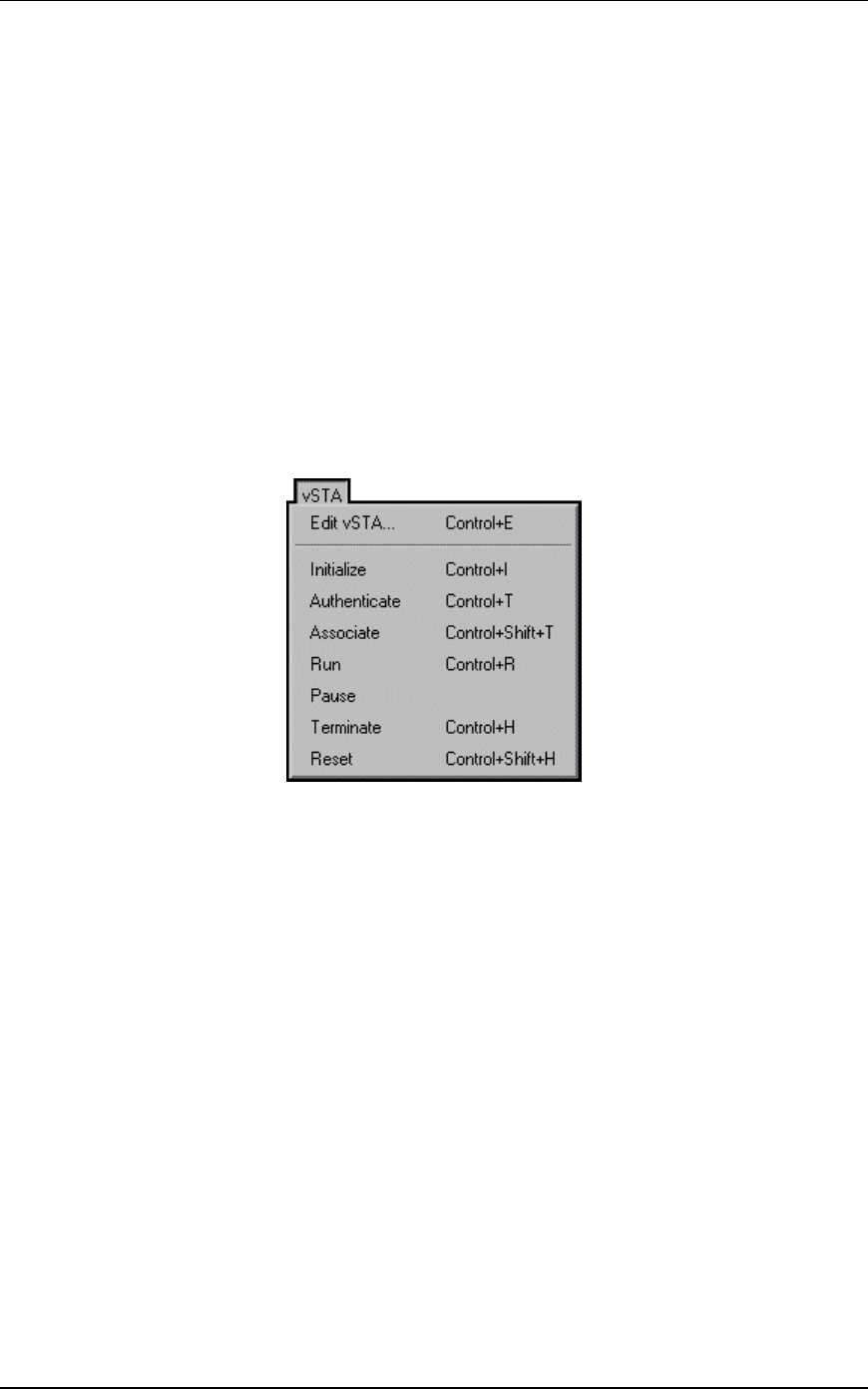
EmulationEngine 11a/b/g User's Guide
Rev #/Date: 2.0.0 Beta/07.17.03 5-71
Associate: When this option is selected, all virtual stations in the
currently selected group will initiate the association sequence to
the System Under Test.
Run: Start execution of all virtual stations defined in the currently
selected group(s).
Pause: Pause execution of all virtual stations defined in the
currently selected group(s). This option will be grayed-out (not
selectable) if the group is not running a test.
Terminate: Stop all virtual stations defined in the currently
selected group(s). This option will be grayed-out (not selectable) if
the group is not running a test.
Reset: Reset all virtual stations defined in the currently selected
group(s).
vSTA Menu
Edit vSTA...: This selection will display the virtual station
configuration dialog.
Initialize: Initialize the currently selected virtual station(s).
Authenticate: When this option is selected, the currently selected
virtual station(s) will initiate the authentication sequence to the
System Under Test.
Associate: When this option is selected, the currently selected
virtual station(s) will initiate the association sequence to the
System Under Test.
Run: Start execution of the currently selected virtual station(s).
Pause: Pause the execution of the currently selected virtual
station(s). This option will be grayed-out (not selectable) if the
virtual station is not running a test.
Terminate: Stop the currently selected virtual station(s). This
option will be grayed-out (not selectable) if the virtual station is
not running a test.
Reset: Reset the currently selected virtual station(s).
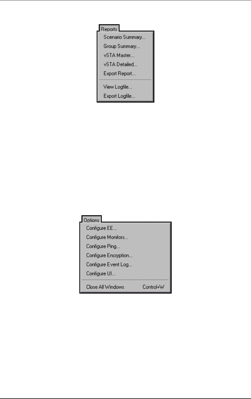
Communication Machinery Corporation (CMC)
5-72 Rev #/Date: 2.0.0 Beta/07.17.03
Reports Menu
Scenario Summary...: Display the scenario summary statistics
report.
Group Summary...: Display the group summary statistics report.
vSTA Master...: Display the virtual station master (i.e.,
EmulationEngine) statistics report.
vSTA Detailed...: Display the virtual station detailed statistics
report.
Export Report...: Display the Generate Report dialog.
View Logfile...: Display event log.
Export Logfile: Display the Export Logfile dialog.
Options Menu
Configure EE...: Display the Configure Emulator dialog.
Configure Monitors...: Display the Configure Monitoring dialog.
Configure Ping...: Display the Configure Ping dialog.
Configure Encryption...: Display the Configure Encryption dialog.
Configure Event Log...: Display the Configure Event Log dialog.
Configure UI...: Display the UI (User Interface) Configuration dialog.

EmulationEngine 11a/b/g User's Guide
Rev #/Date: 2.0.0 Beta/07.17.03 5-73