J Three Holding BU2073J Bluetooth Adaptor User Manual M Turbo Ultrasound System User Guide
J-Three International Holding Co., Ltd Bluetooth Adaptor M Turbo Ultrasound System User Guide
Contents
- 1. Users Manual
- 2. User Guide Supplement
- 3. User Manual M Turbo
- 4. User Manual S Series
- 5. Setup Instructions
User Manual M Turbo
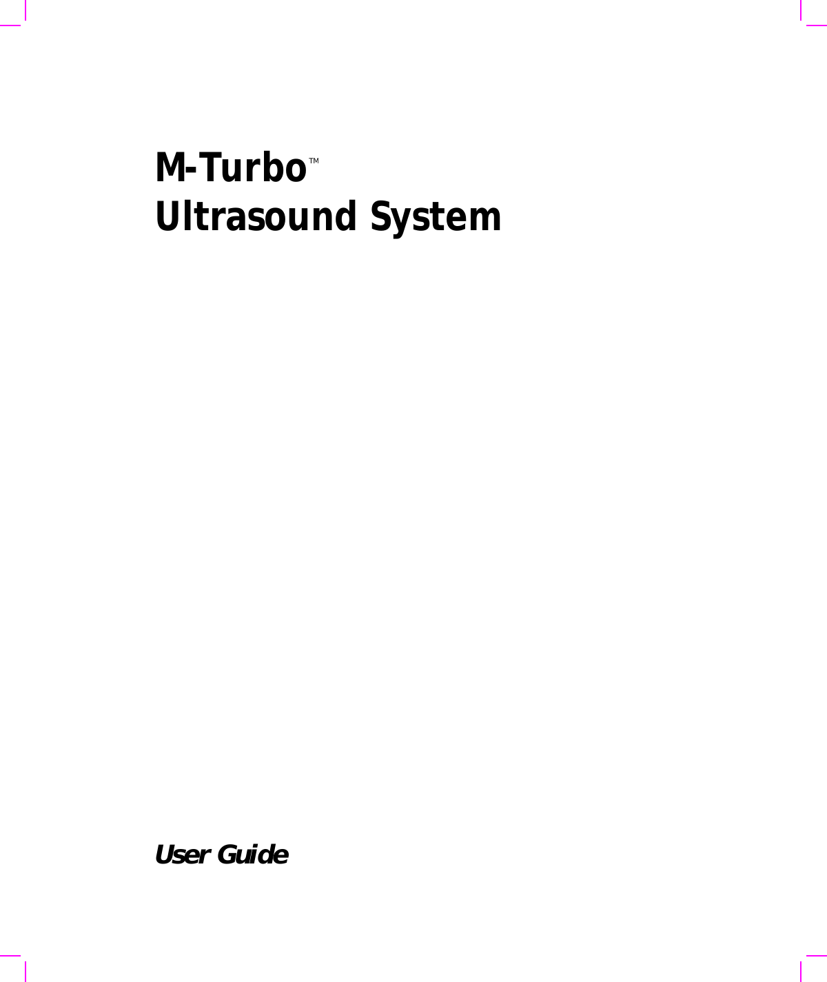
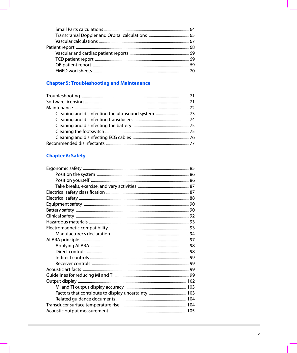

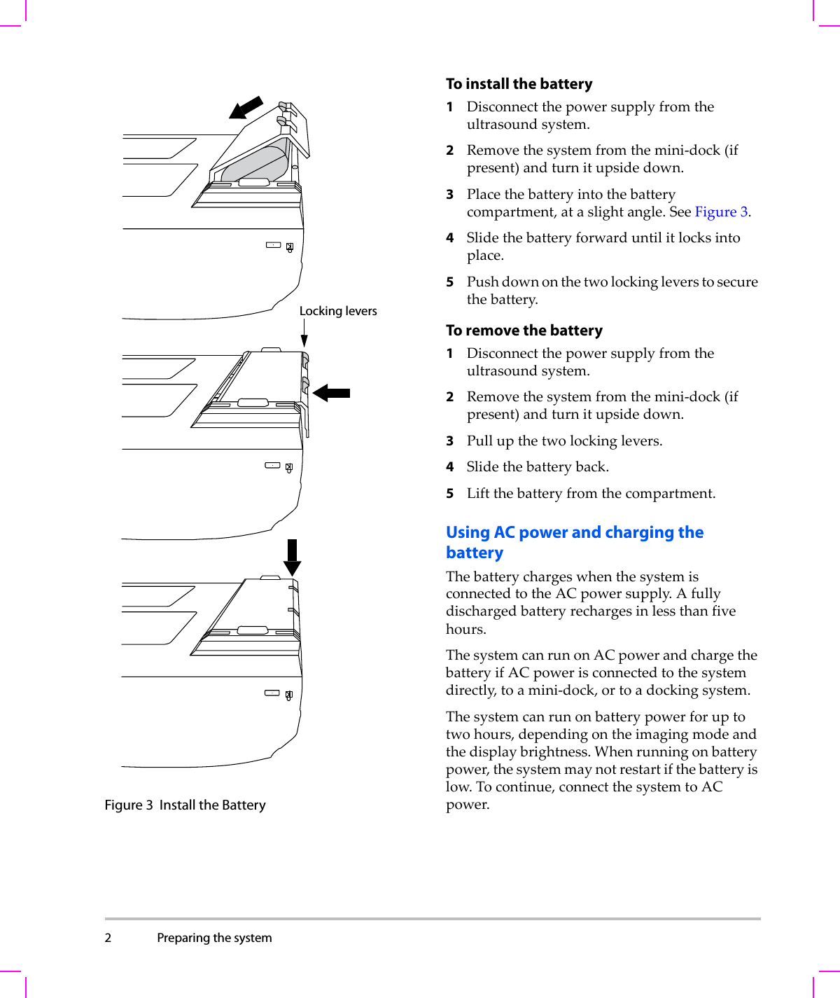
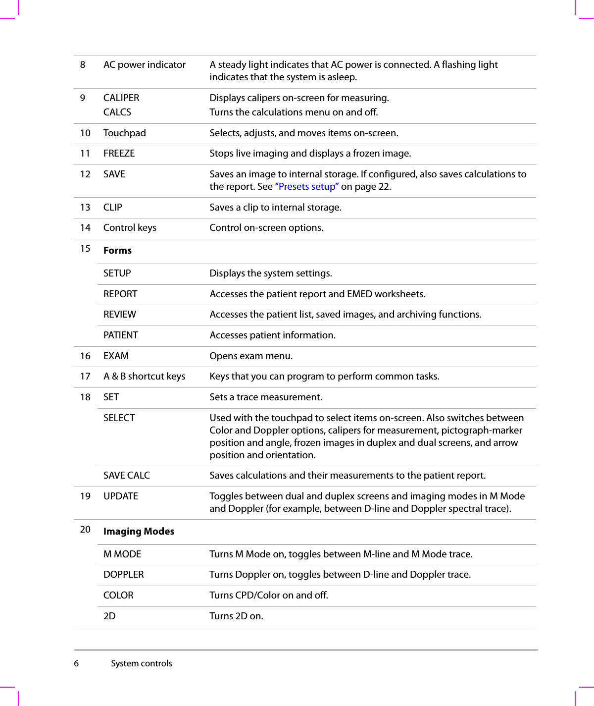
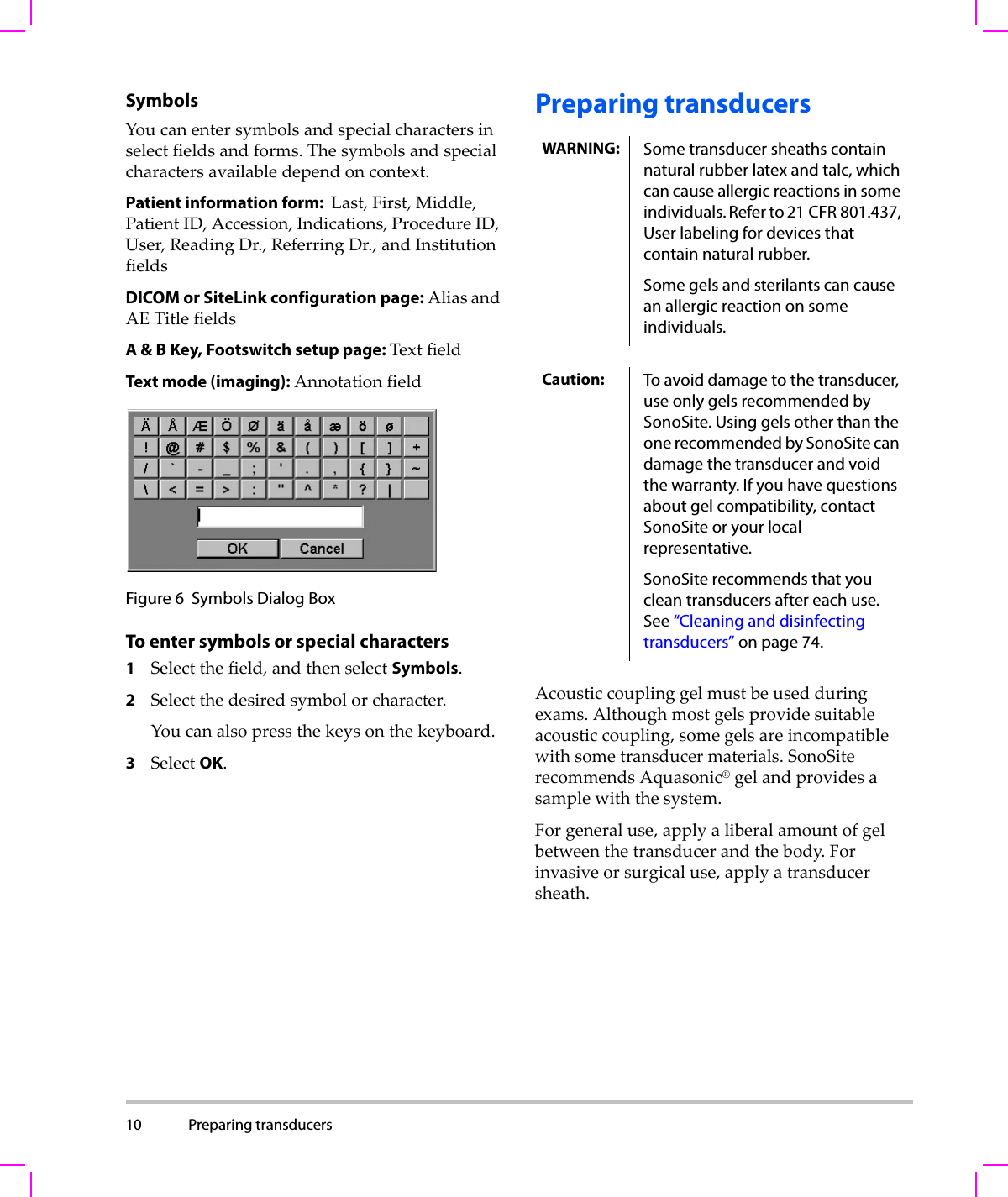


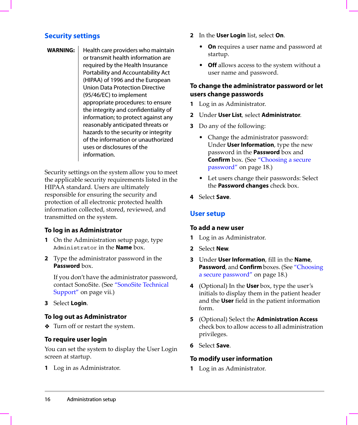
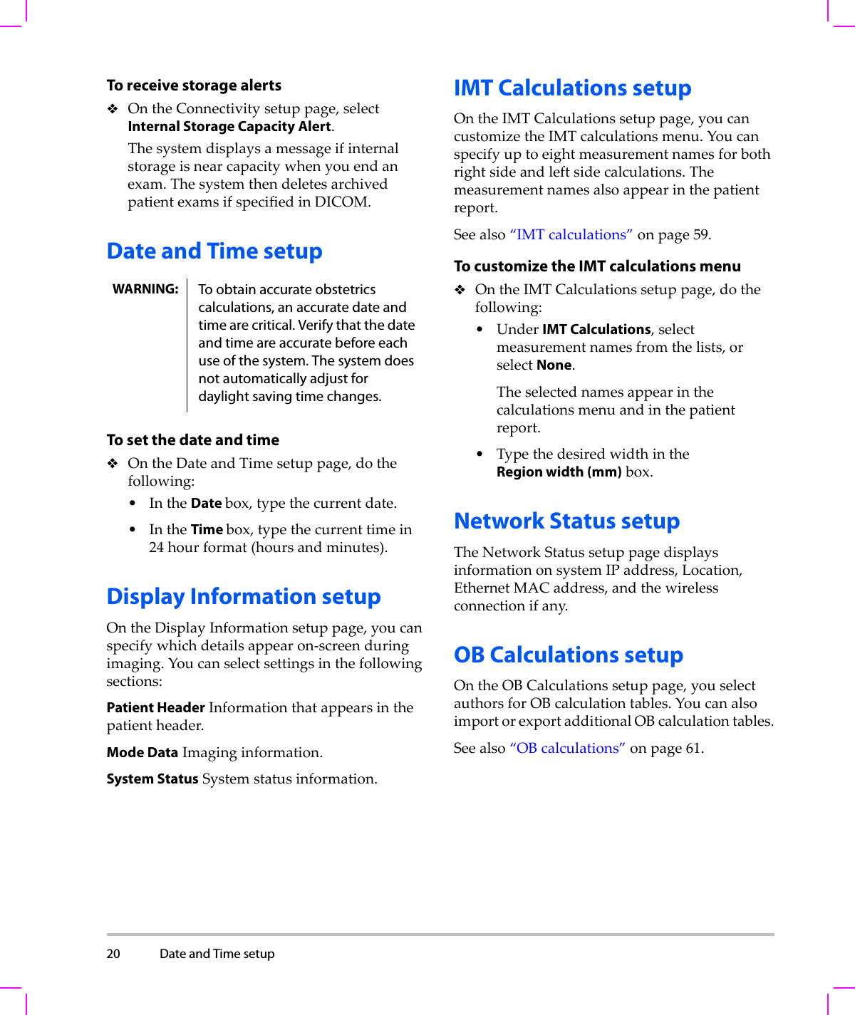

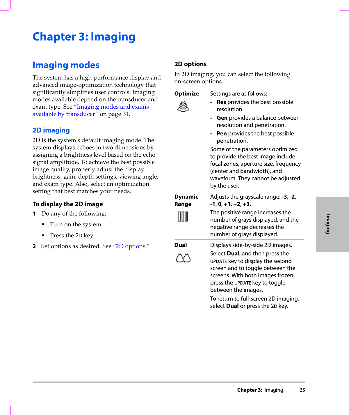
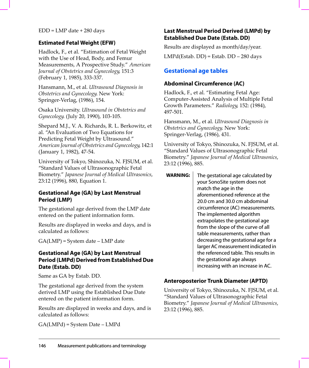
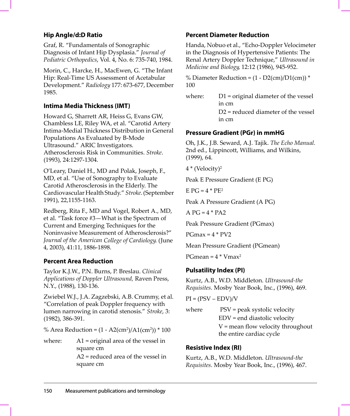
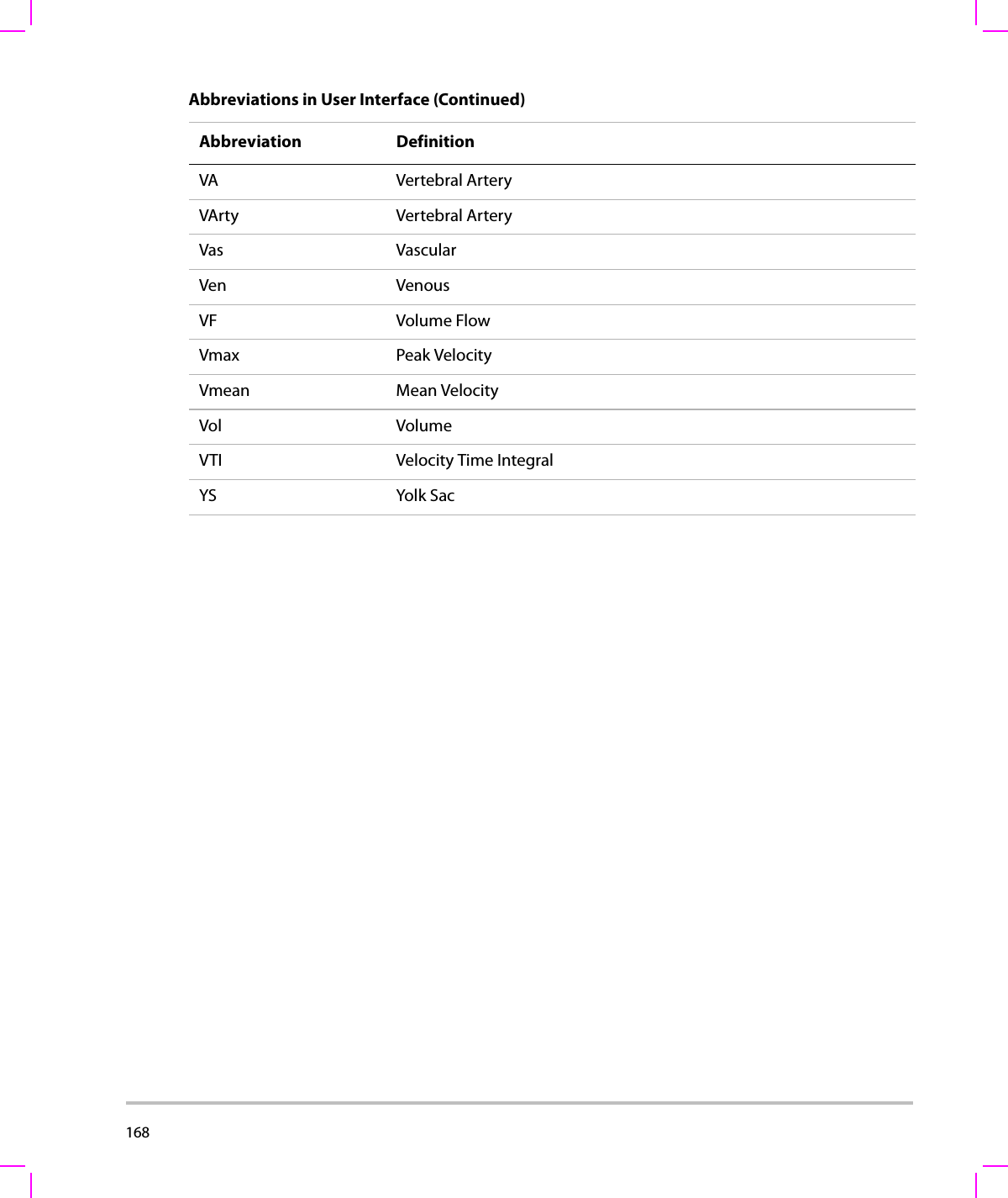
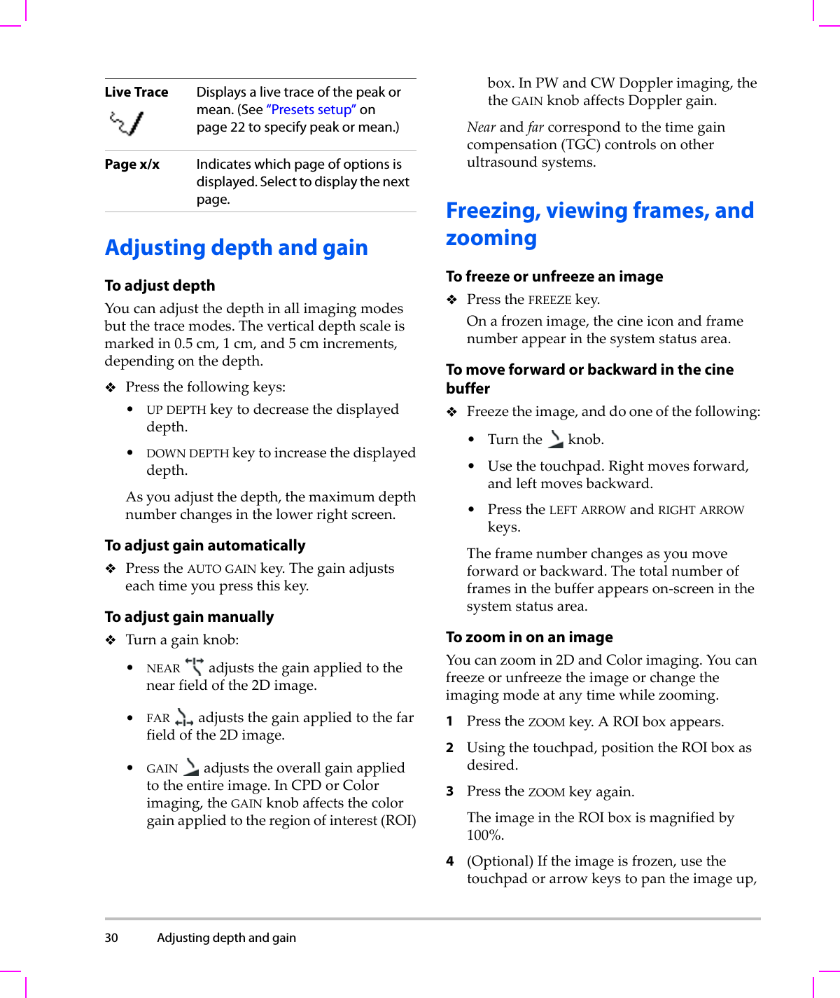
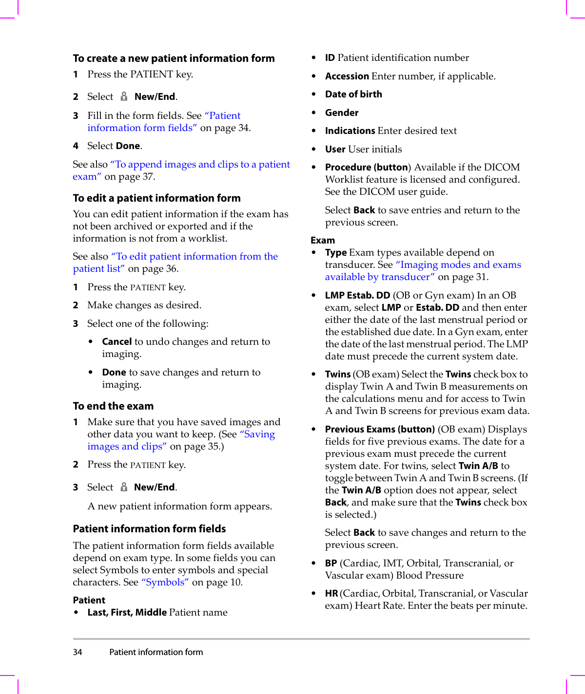
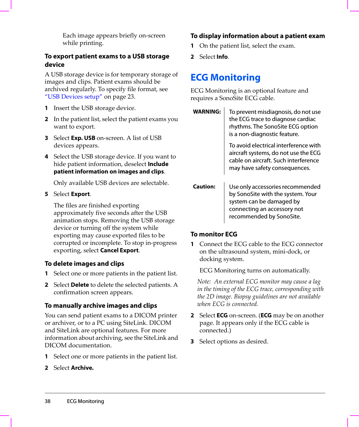
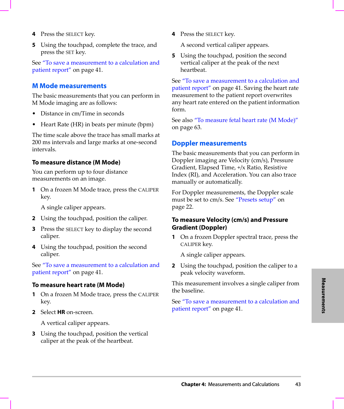
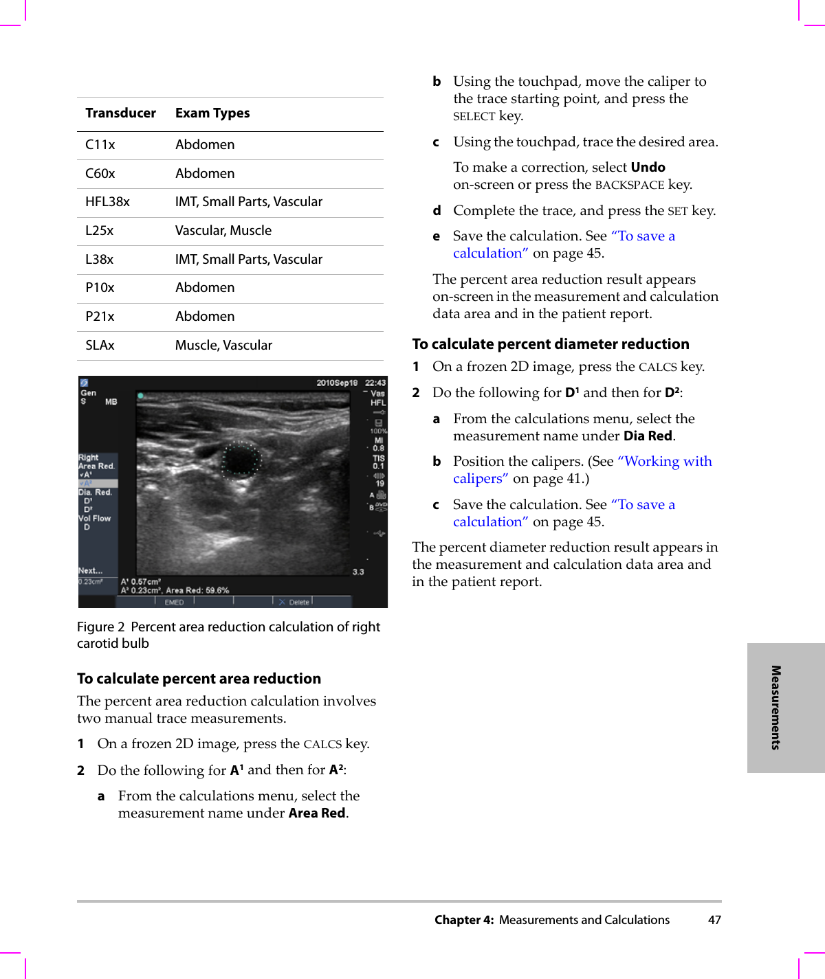
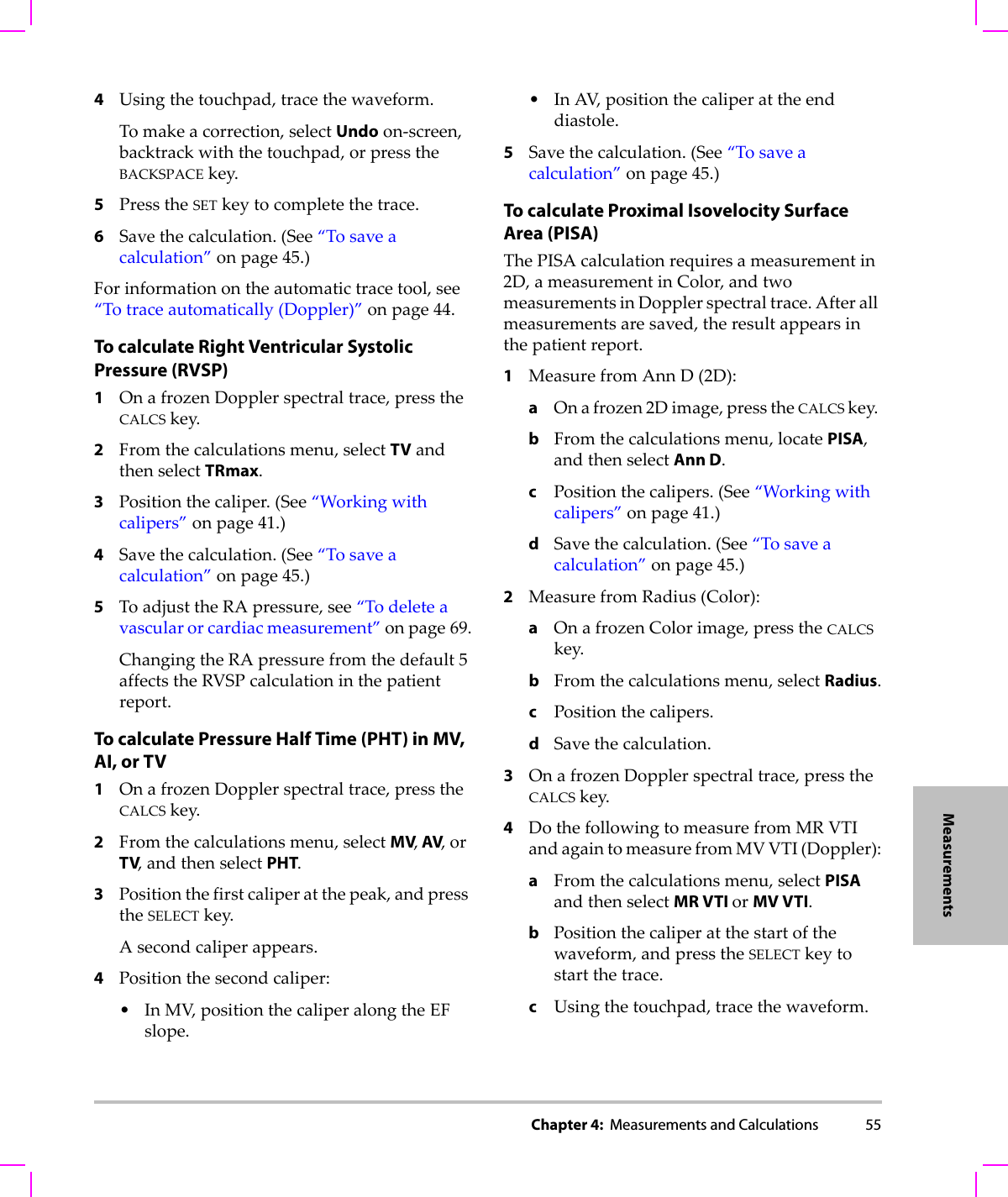
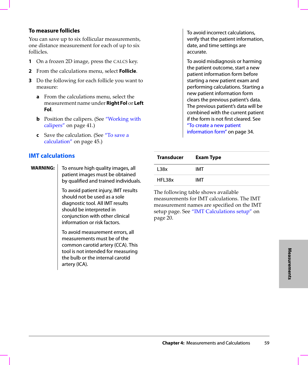
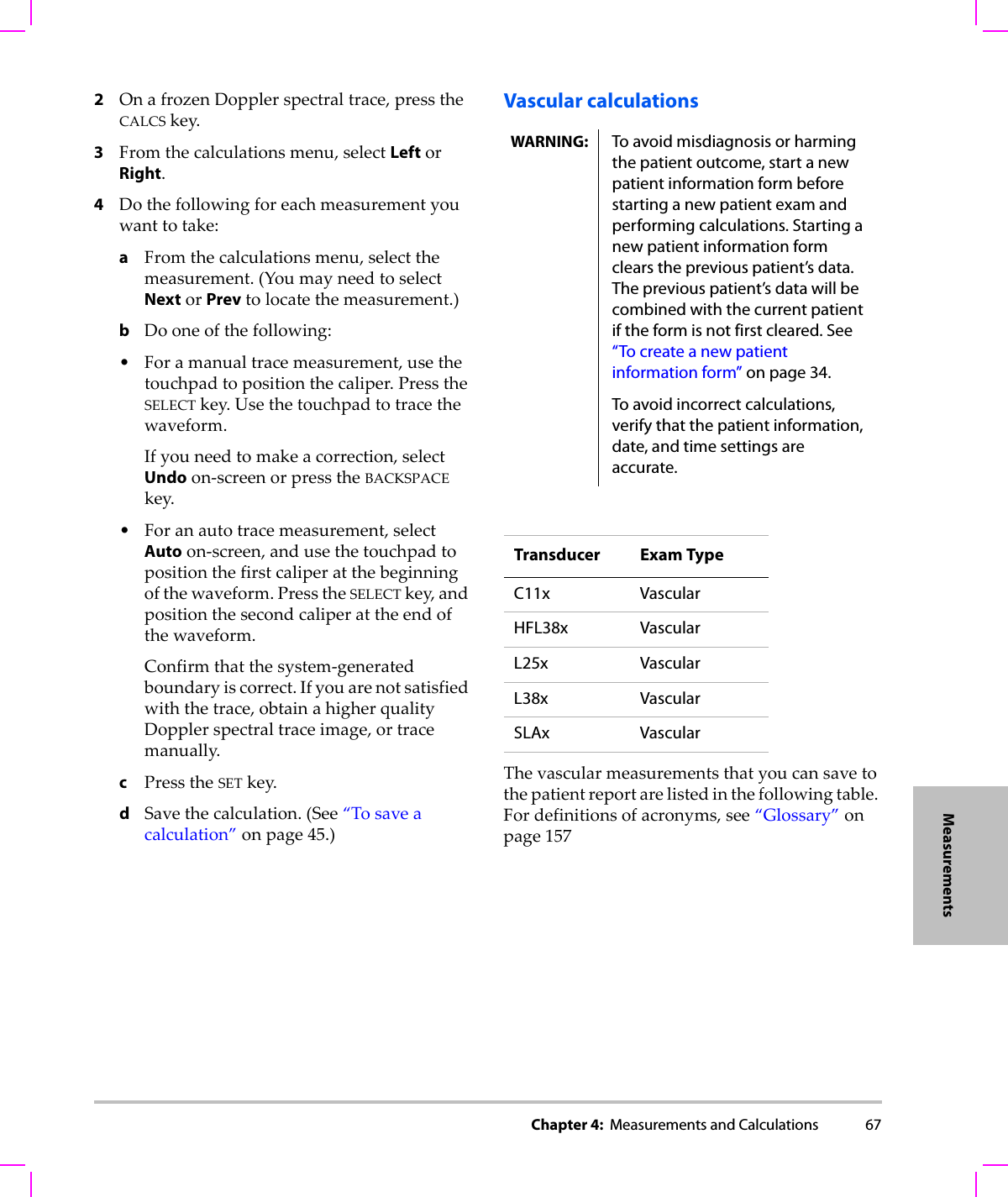
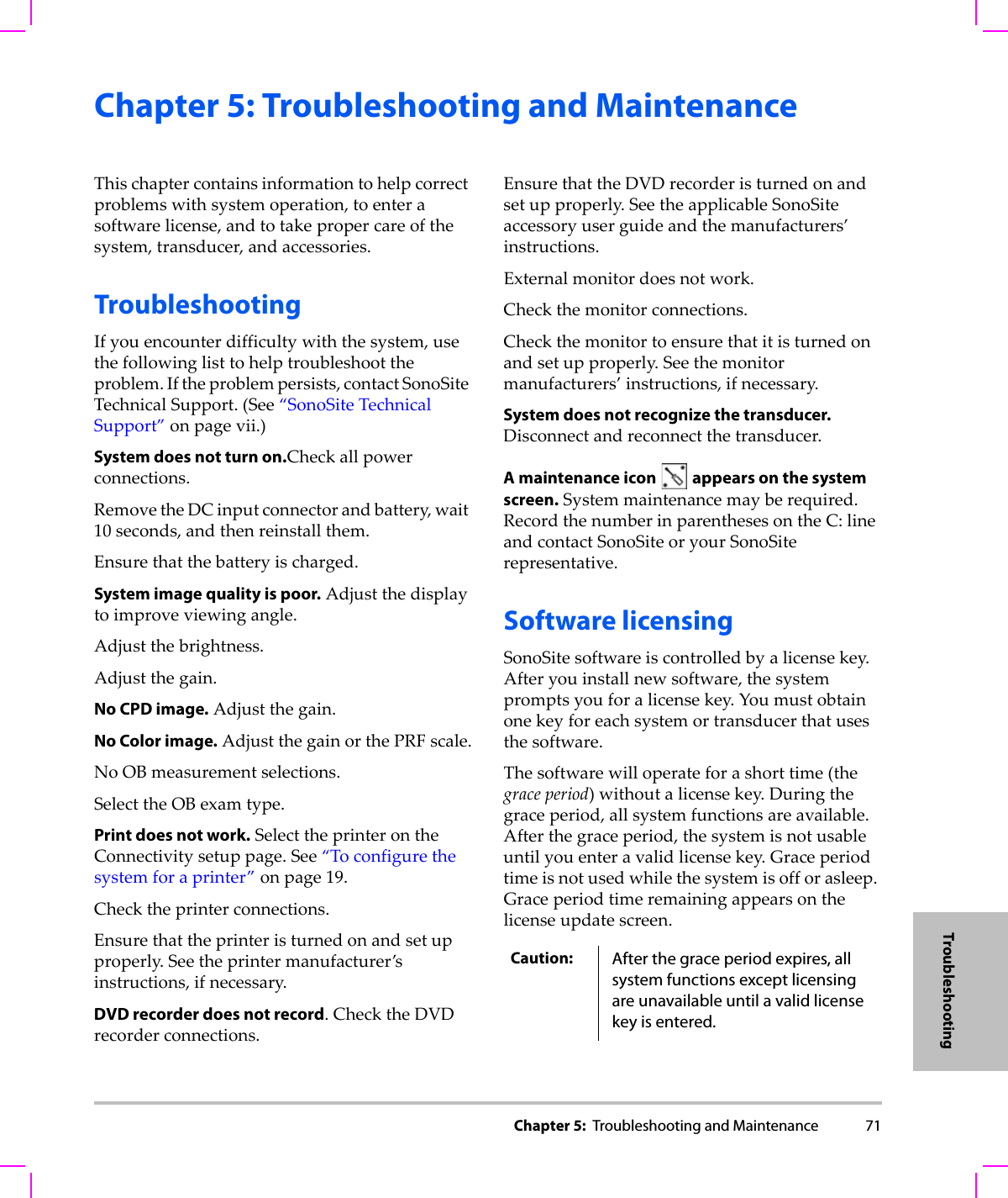
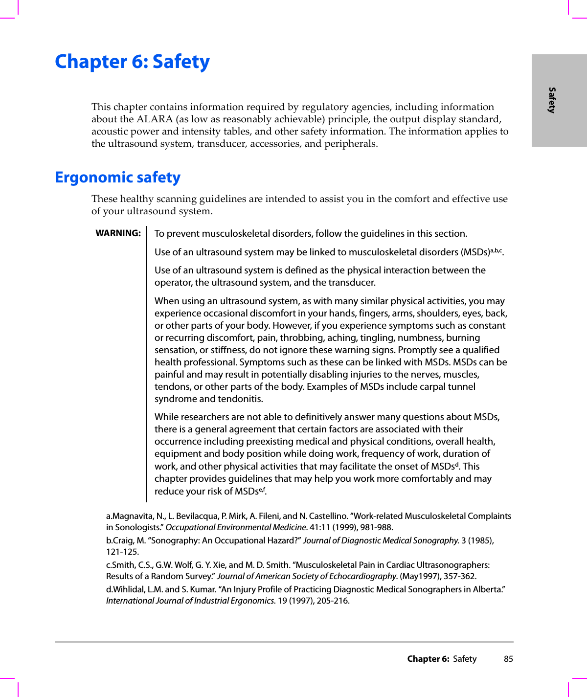
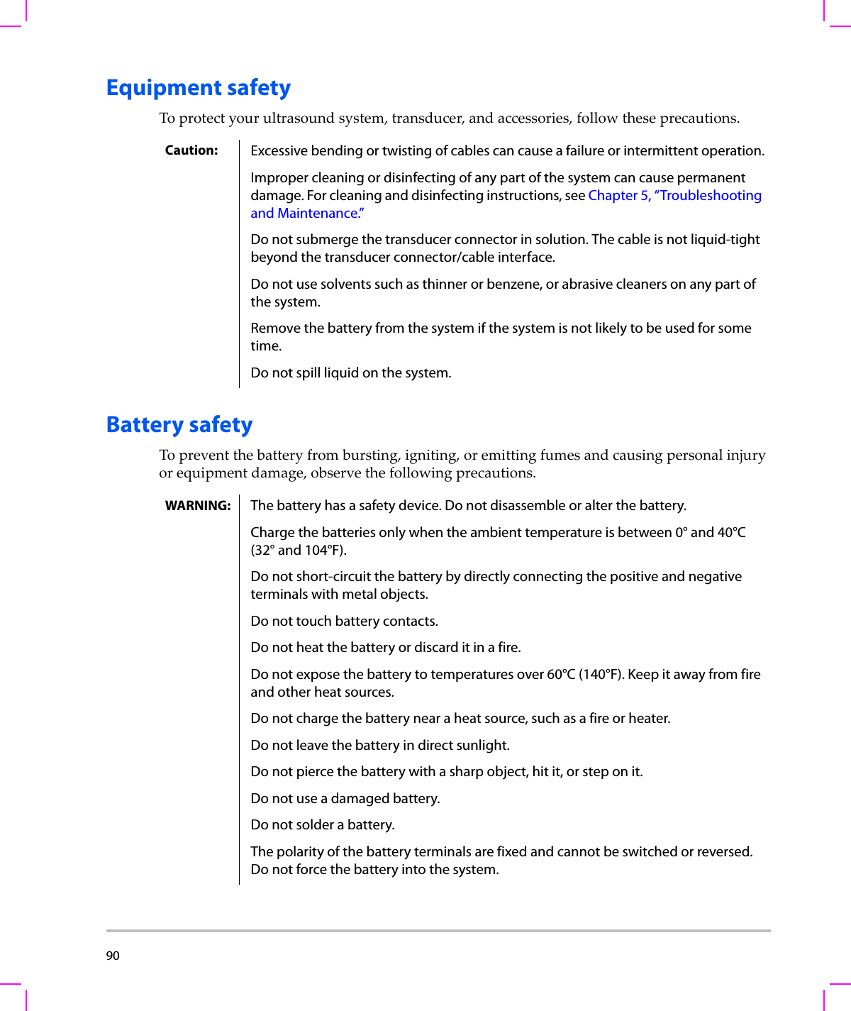
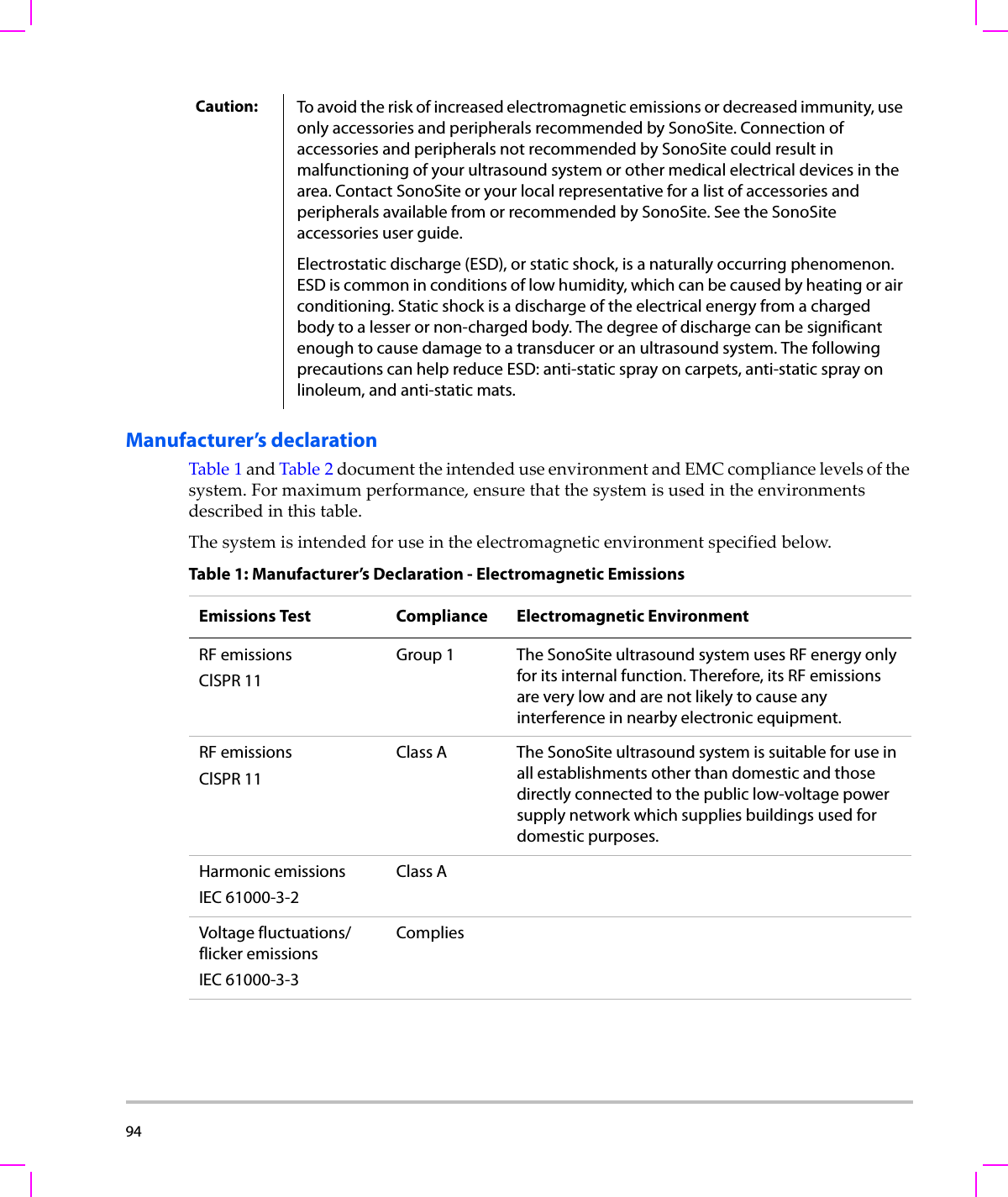
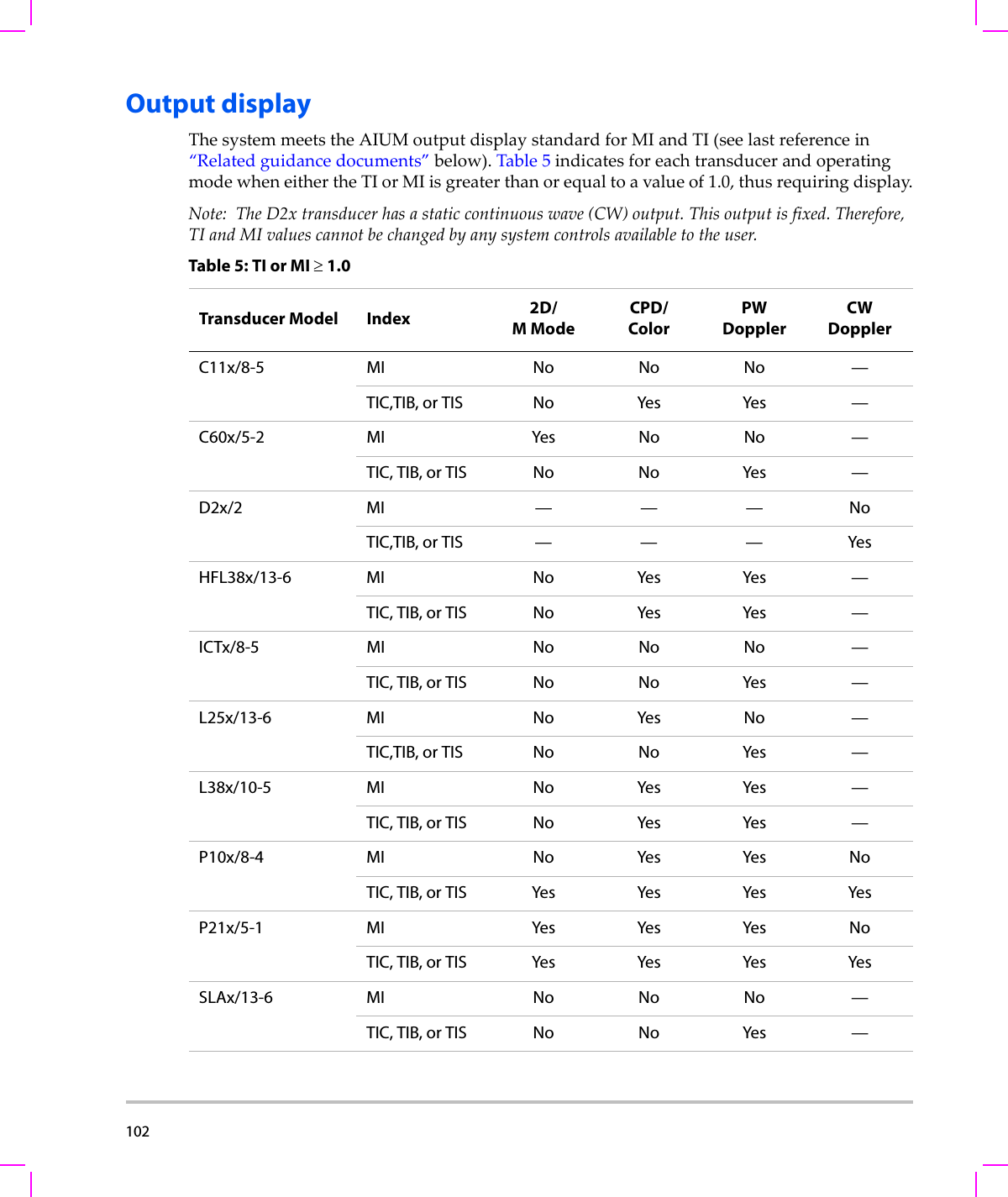
![Chapter 3: Imaging 29Imaging•Ifusingaduplexlayout,presstheDOPPLERkeytotogglebetweenthefull‐screenD‐lineandtheduplexlayout.Tosetaduplexlayout,see“Presetssetup”onpage 22.PW Doppler optionsInPWDopplerimaging,youcansetthefollowingon‐screenoptions.Spectral trace optionsInspectraltraceimaging,youcansetthefollowingon‐screenoptions.PW, CW (Cardiac exam only) Toggle between PW Doppler and CW Doppler. The current selection appears in the upper left-hand screen.Angle CorrectionCorrects the angle to 0°, +60°, or -60°.Gate Size Settings depend on transducer and exam type.In TCD or Orb exams, use the touchpad to specify the Doppler gate depth (the depth of the center of the gate in the Doppler image). The Doppler gate depth indicator is on the lower right-hand screen. TDI On, TDI OffSelect TDI On to turn on tissue Doppler imaging. When on, TDI appears in the upper left-hand screen. The default is TDI off.Available only in cardiac exams.Steering Select the desired steering angle setting. The PW Doppler angle correction automatically changes to the optimum setting.•-15 has an angle correction of -60°.•0 has an angle correction of 0°.•+15 has an angle correction of +60°.You can manually correct the angle after selecting a steering angle setting. (See “To display the D-line” on page 28.)Available on select transducers.Page x/x Indicates which page of options is displayed. Select to display the next page.Scale Select the desired scale (pulse repetition frequency [PRF]) setting.(To change the Doppler scale to cm/s or kHz, see “Presets setup” on page 22.)Line Sets the baseline position.(On a frozen trace, the baseline can be adjusted if Live Trace is off.)Invert Vertically flips the spectral trace.(On a frozen trace, Invert is available if Live Trace is off.)Volume Increases or decreases Doppler speaker volume (0-10).Wall Filter Settings include Low, Med, High.Sweep Speed Settings include Slow, Med, Fast.](https://usermanual.wiki/J-Three-Holding/BU2073J.User-Manual-M-Turbo/User-Guide-1089450-Page-39.png)
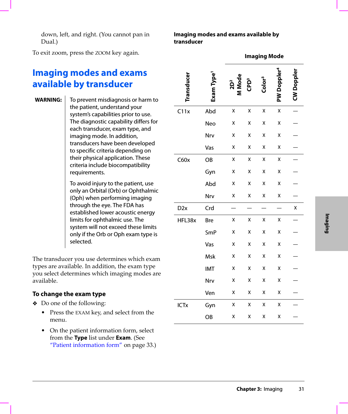
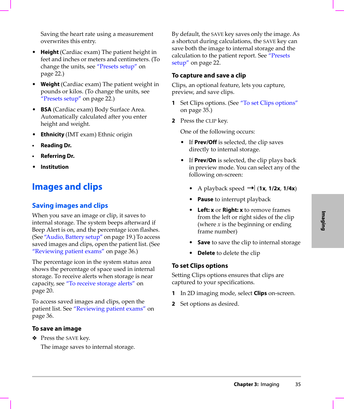
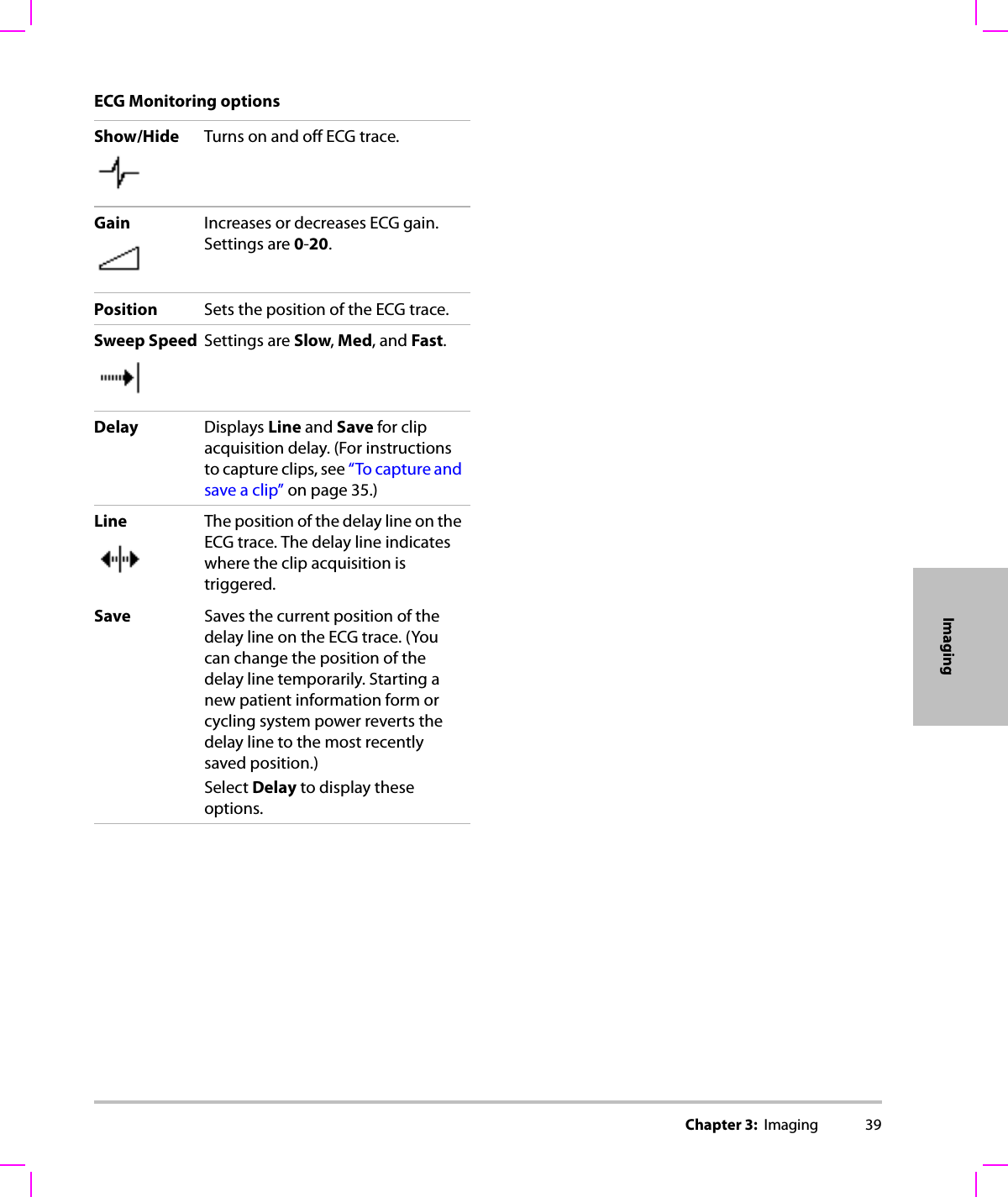

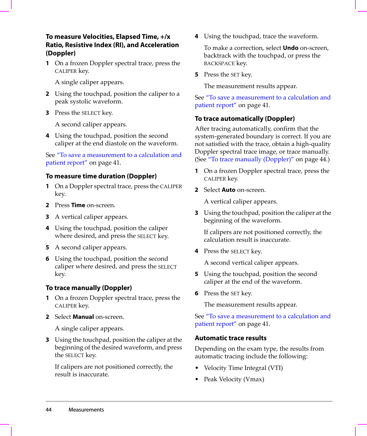
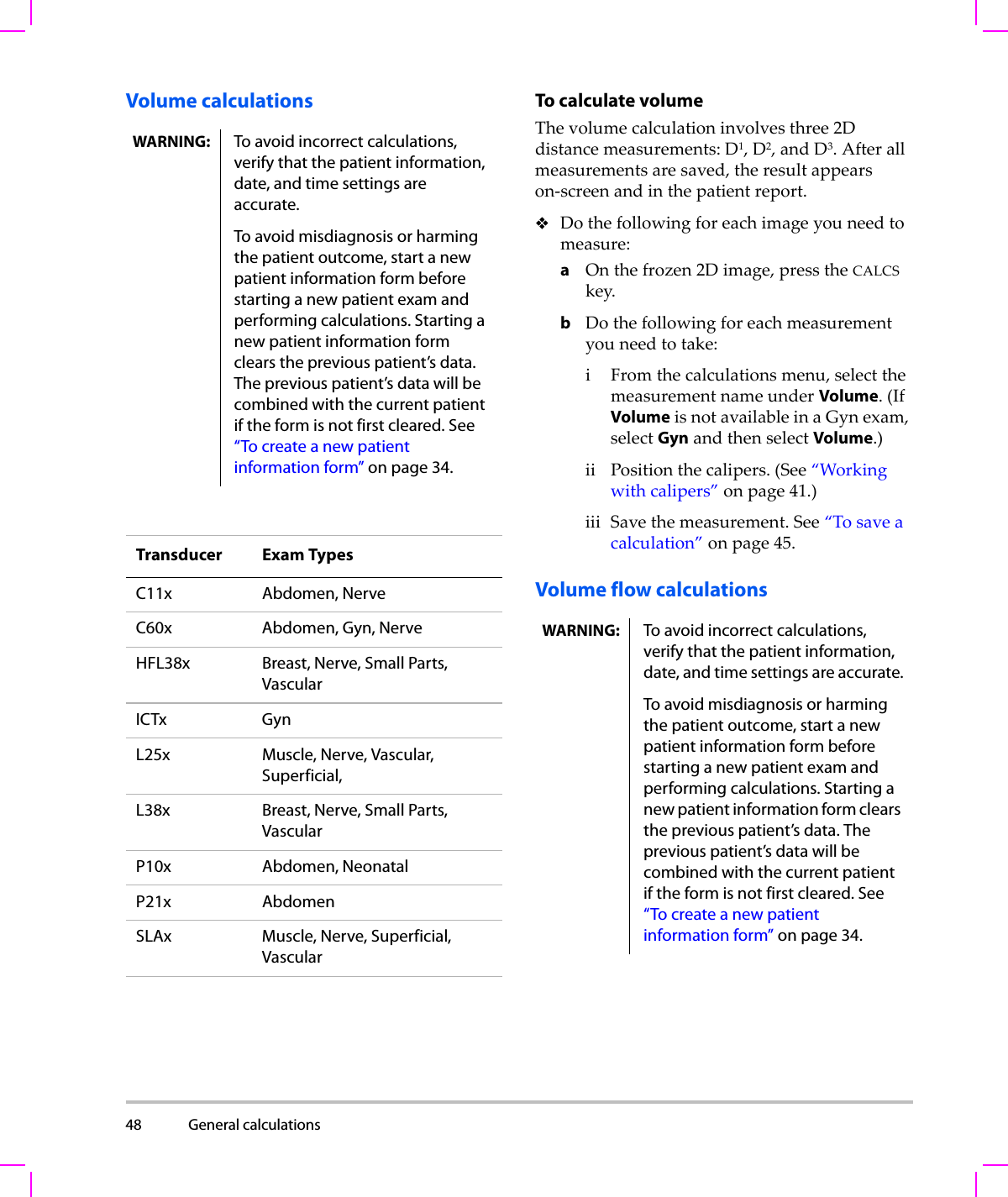
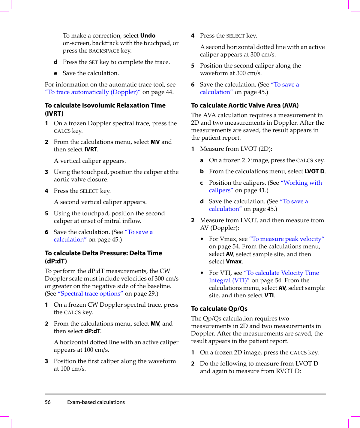
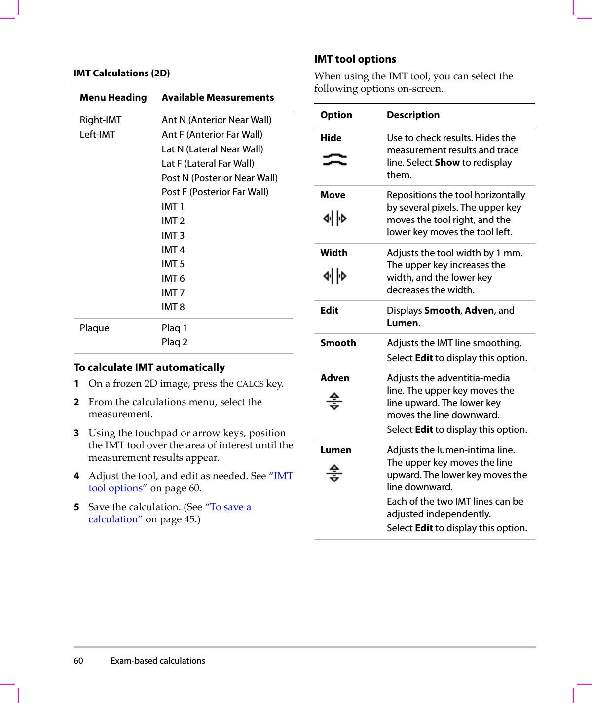
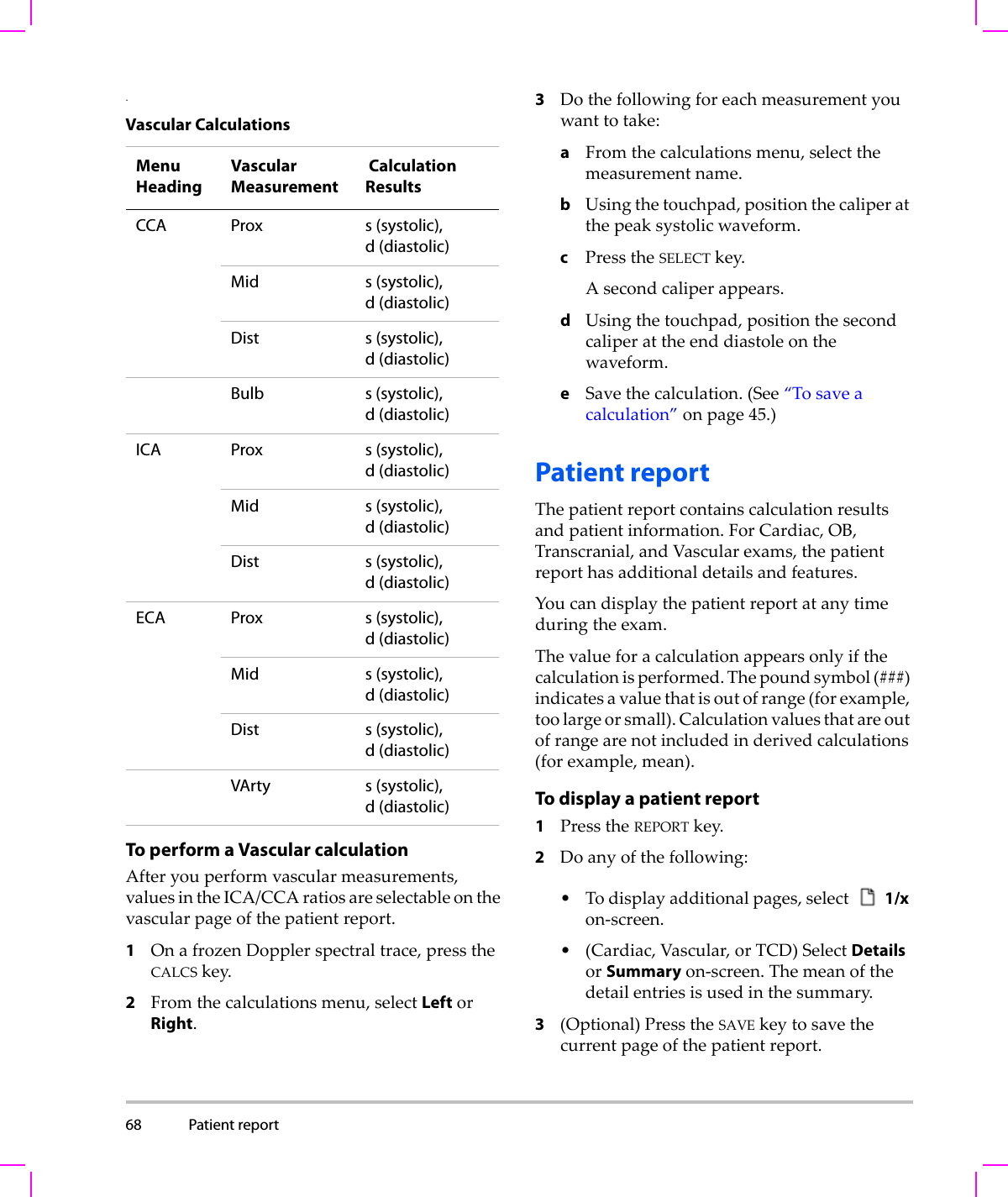
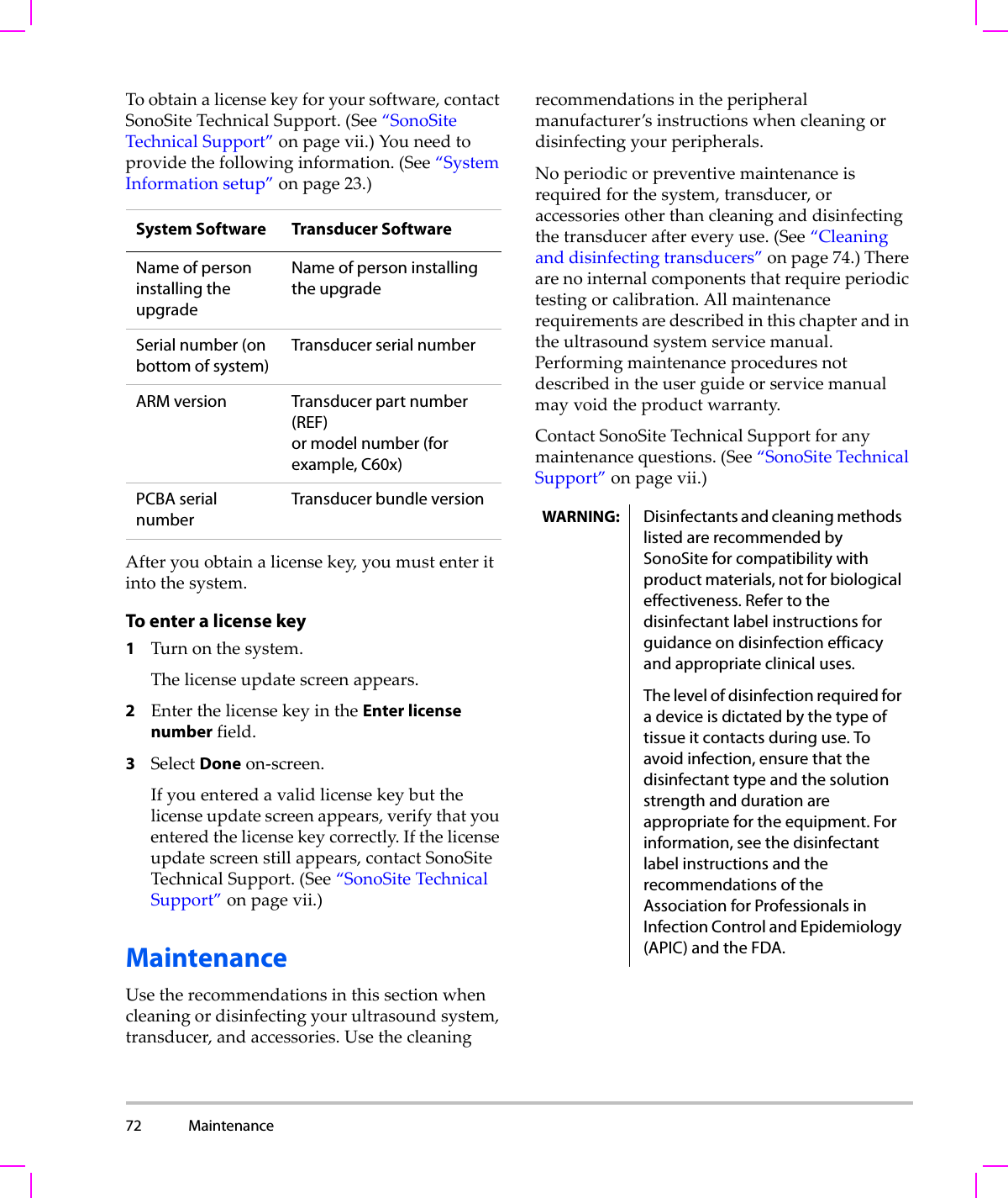


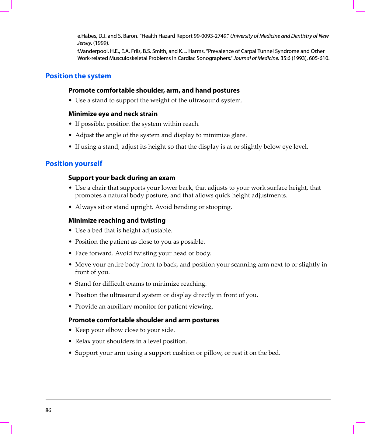

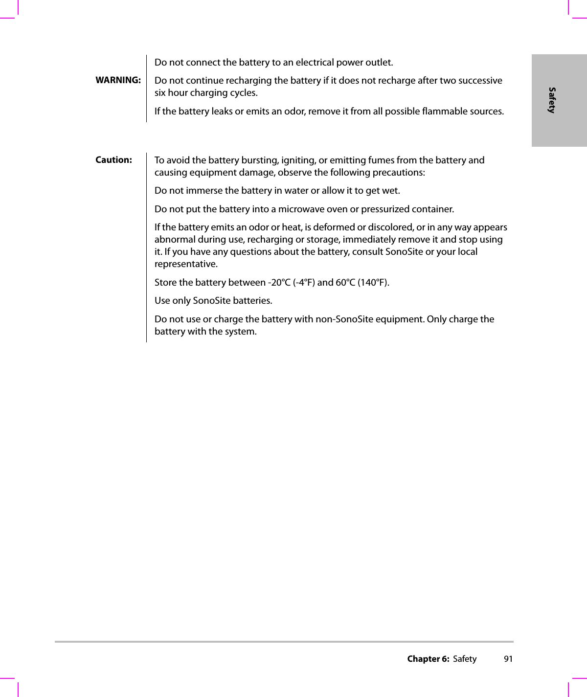
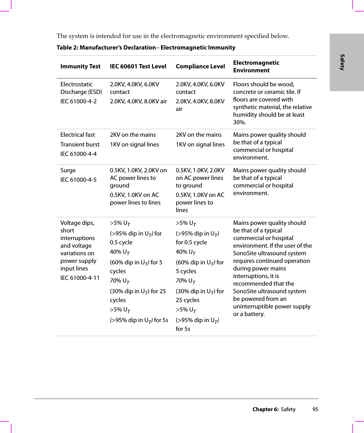
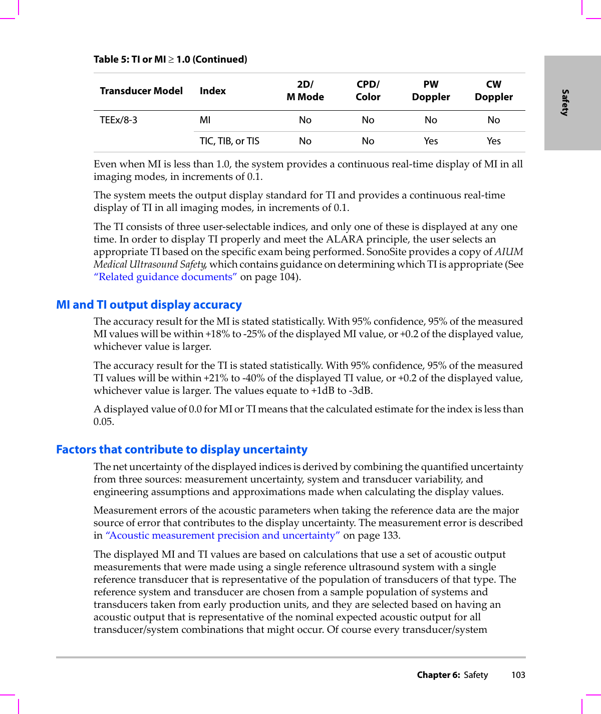
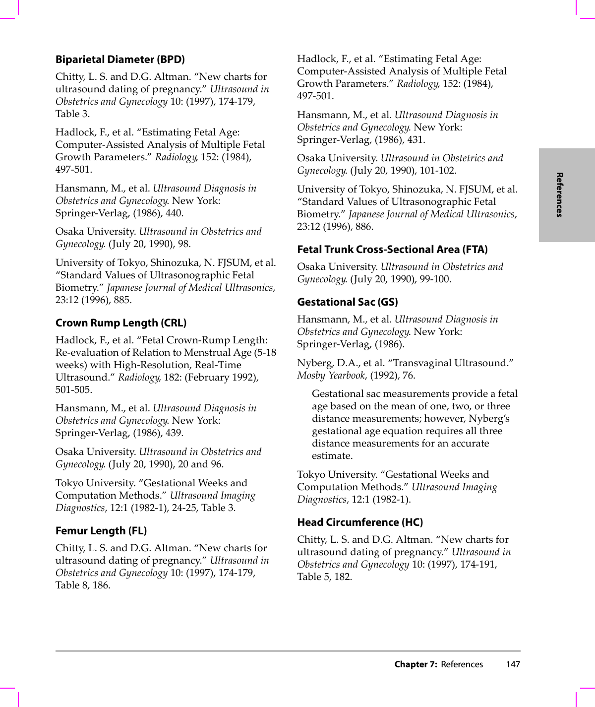
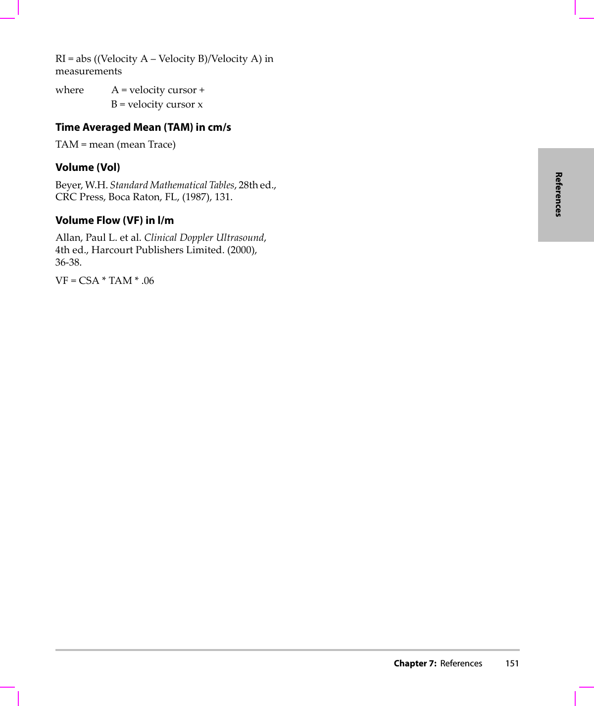
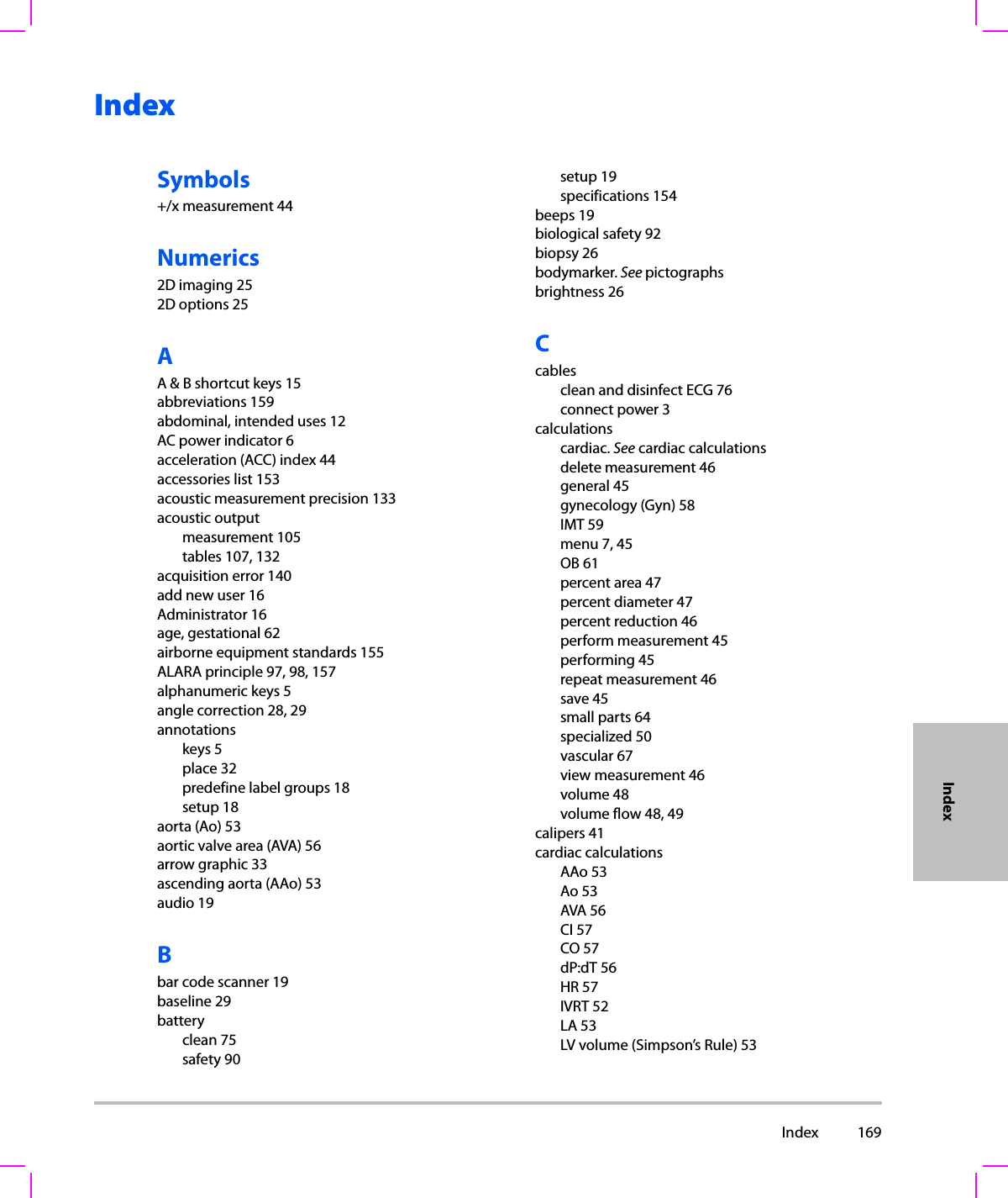
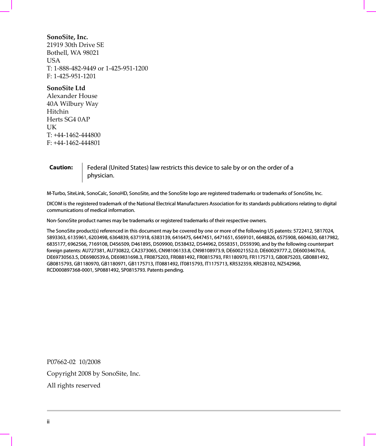
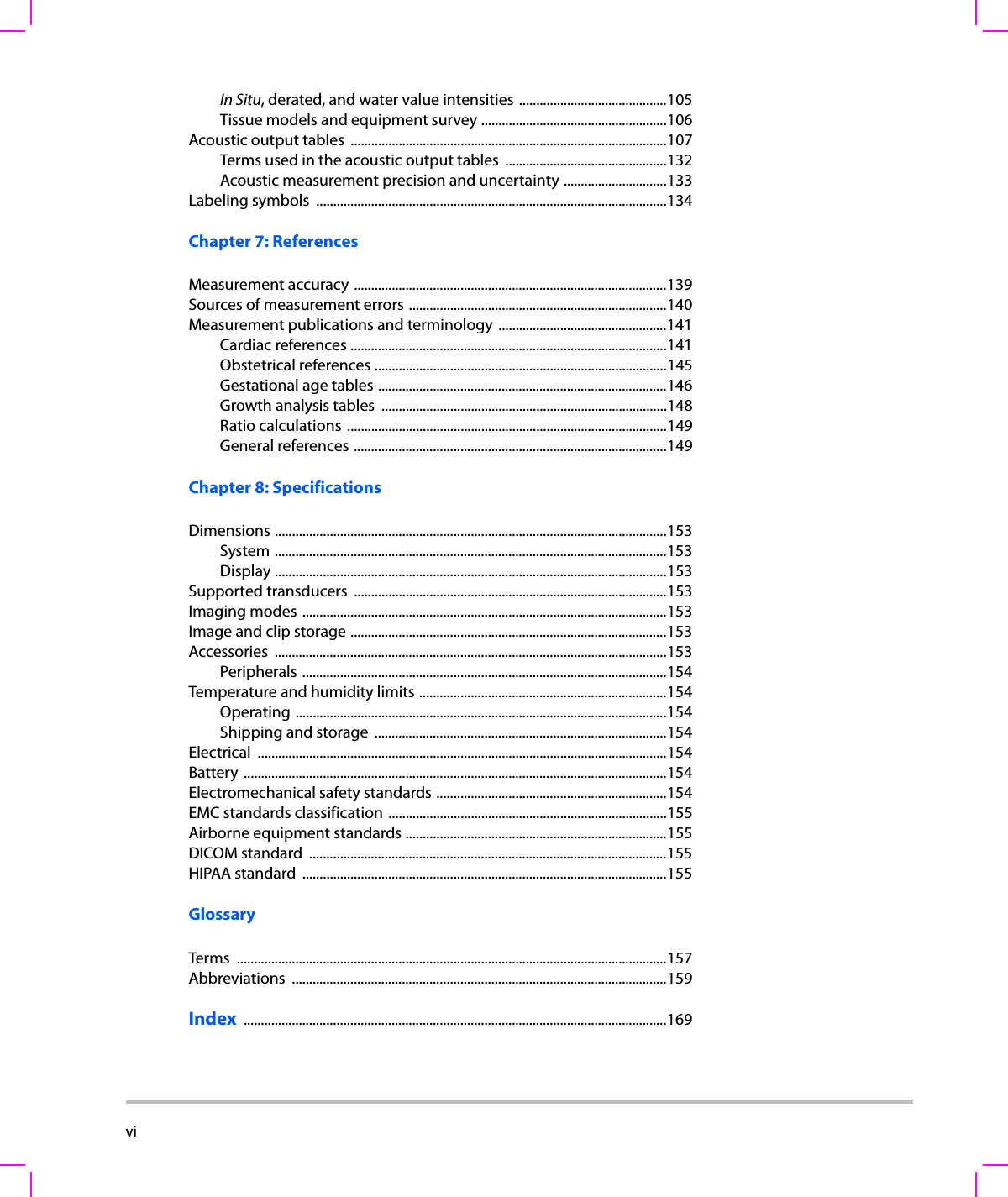
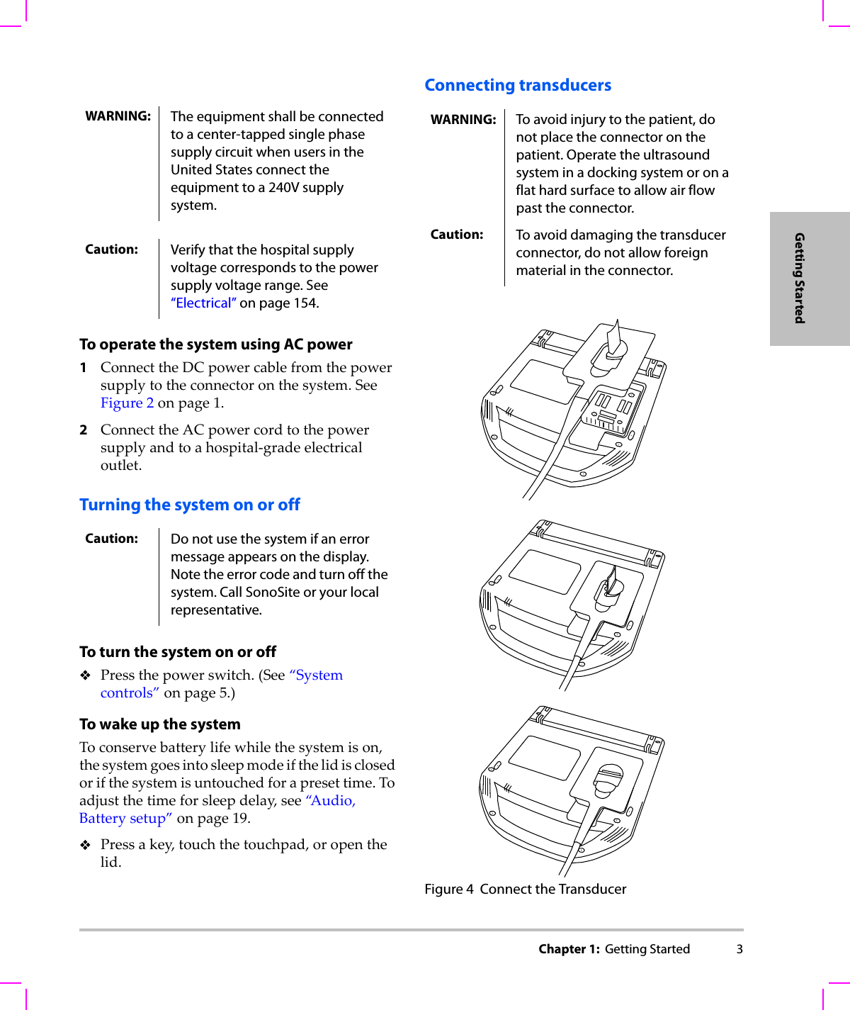
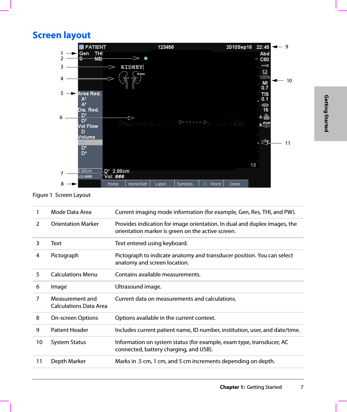
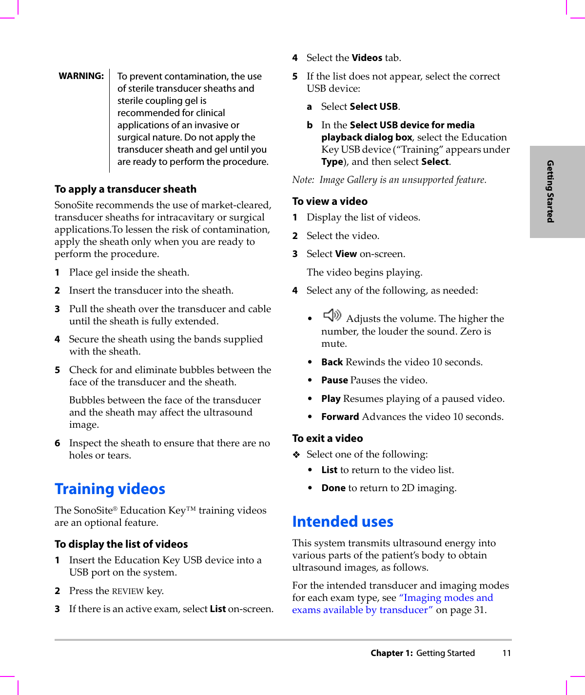
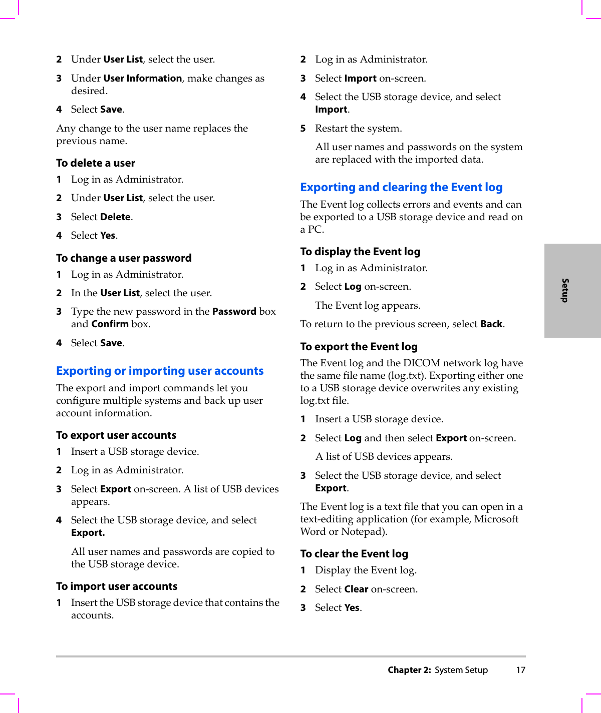
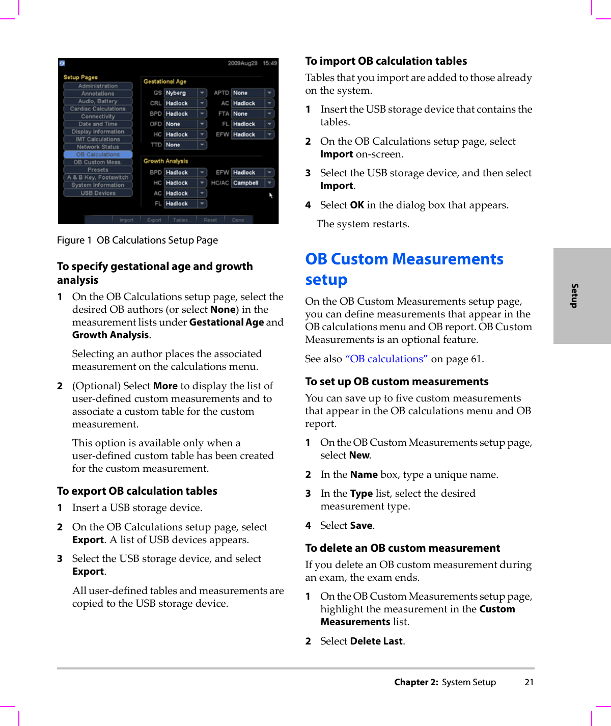
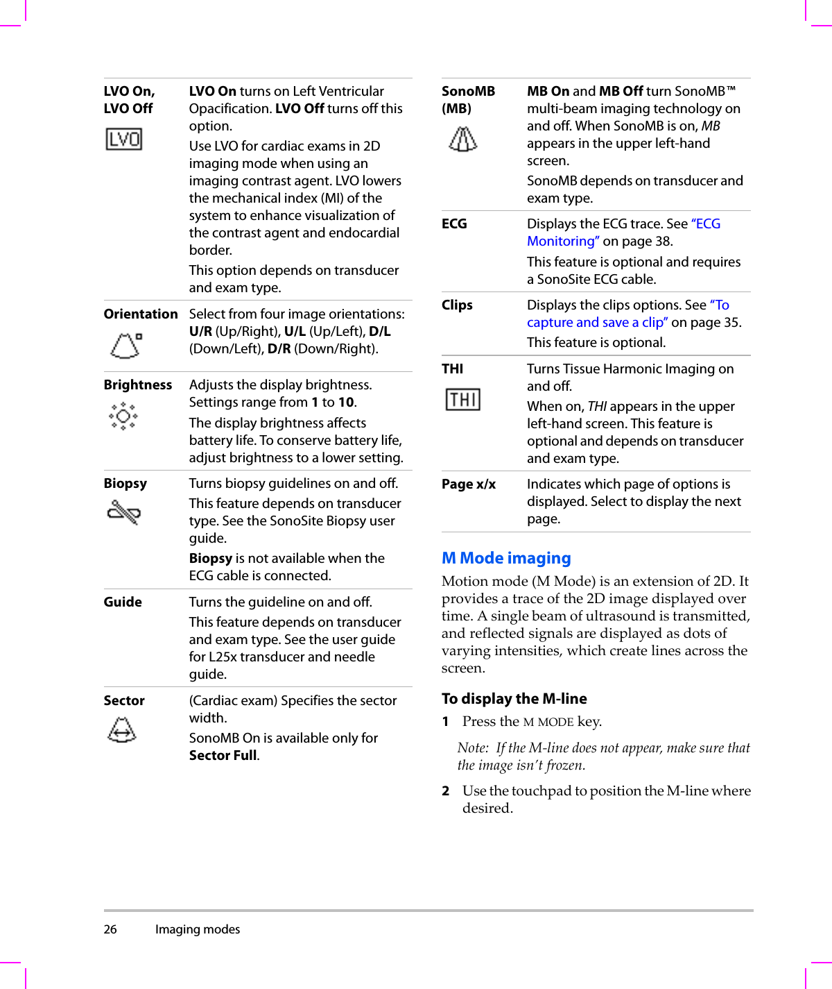
![Chapter 6: Safety 105SafetyAcoustic output measurementSincetheinitialuseofdiagnosticultrasound,thepossiblehumanbiologicaleffects(bioeffects)fromultrasoundexposurehavebeenstudiedbyvariousscientificandmedicalinstitutions.InOctober1987,theAmericanInstituteofUltrasoundinMedicine(AIUM)ratifiedareportfromitsBioeffectsCommittee(BioeffectsConsiderationsfortheSafetyofDiagnosticUltrasound,JUltrasoundMed.,Sept.1988:Vol.7,No.9Supplement).Thereport,sometimesreferredtoastheStoweReport,reviewedavailabledataonpossibleeffectsofultrasoundexposure.Anotherreport,“BioeffectsandSafetyofDiagnosticUltrasound,”datedJanuary28,1993,providesmorecurrentinformation.Theacousticoutputforthisultrasoundsystemhasbeenmeasuredandcalculatedinaccordancewith“A c o u s t i c OutputMeasurementStandardforDiagnosticUltrasoundEquipment”(NEMAUD2‐2004),and“StandardforReal‐TimeDisplayofThermalandMechanicalAcousticOutputIndicesonDiagnosticUltrasoundEquipment”(NEMAUDe3‐2004).In Situ, derated, and water value intensitiesAllintensityparametersaremeasuredinwater.Sincewaterdoesnotabsorbacousticenergy,thesewatermeasurementsrepresentaworstcasevalue.Biologicaltissuedoesabsorbacousticenergy.Thetruevalueoftheintensityatanypointdependsontheamount,typeoftissue,andthefrequencyoftheultrasoundpassingthroughthetissue.Theintensityvalueinthetissue,In Situ,hasbeenestimatedbyusingthefollowingformula:In Situ=Water[e‐(0.23alf)]where:In Situ=In SituintensityvalueWater=Waterintensityvaluee=2.7183a=attenuationfactor(dB/cm MHz)Table 7: Transducer Surface Temperature Rise, Internal Use (°C )Test ICTx SLAx TEExStill air 9.2 9.5 9.3SimulatedUse 5.2 4.8 5.8](https://usermanual.wiki/J-Three-Holding/BU2073J.User-Manual-M-Turbo/User-Guide-1089450-Page-115.png)
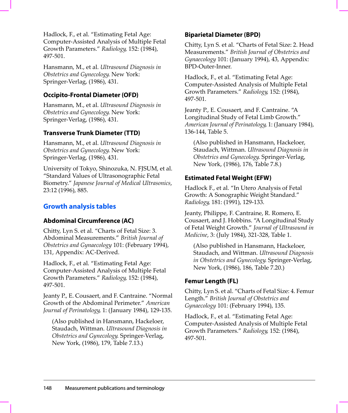
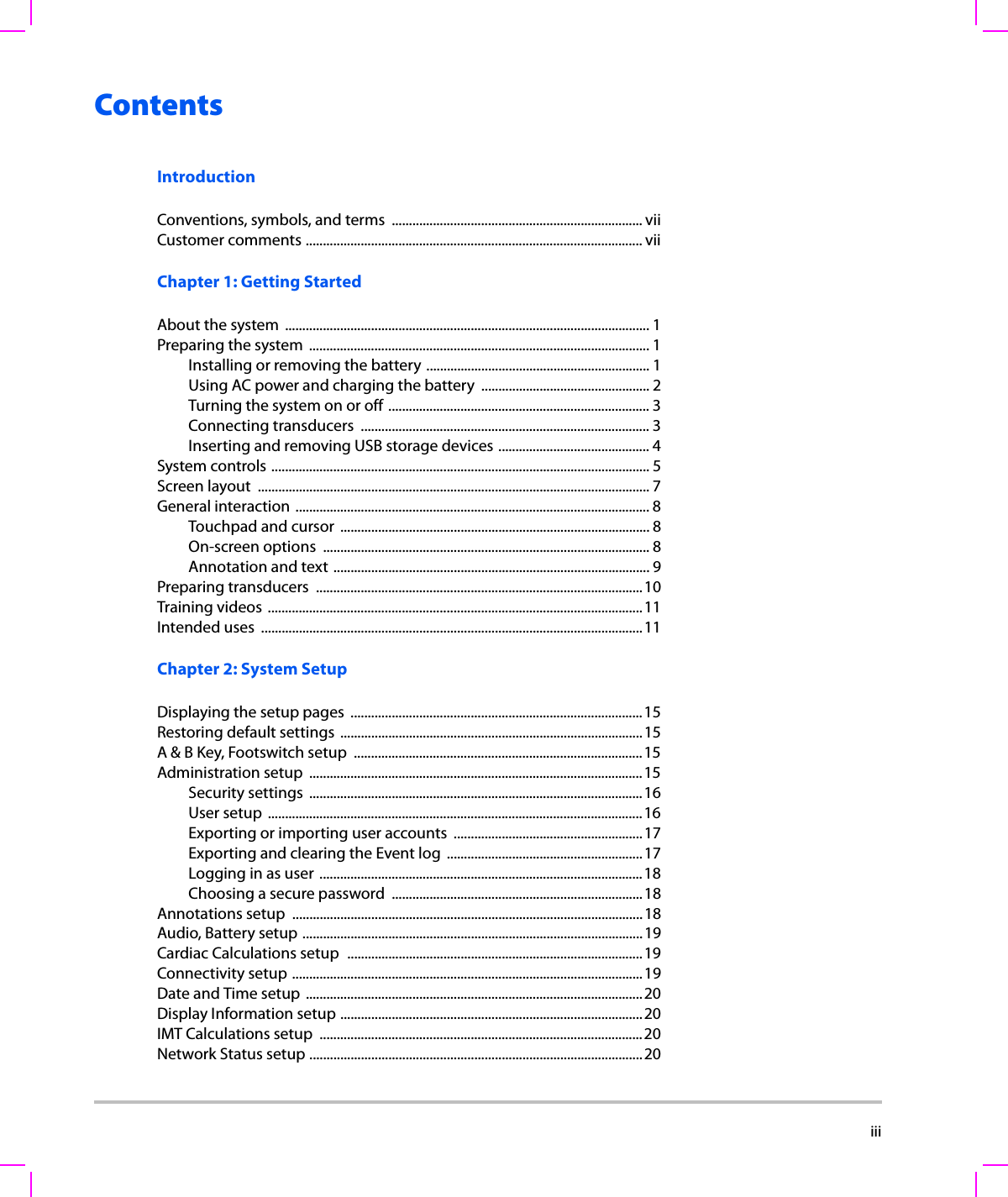
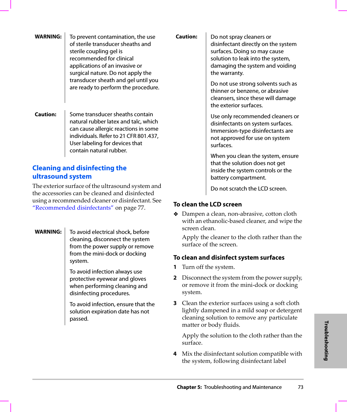
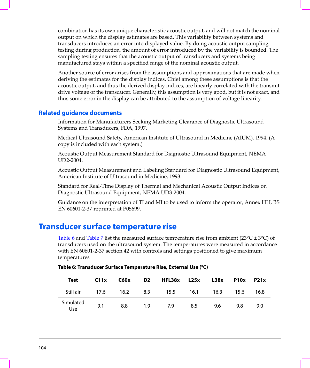
![106 Attenuationfactor(a)forvarioustissuetypesaregivenbelow:brain=0.53heart=0.66kidney=0.79liver=0.43muscle=0.55l=skinlinetomeasurementdepthincmf=centerfrequencyofthetransducer/system/modecombinationinMHzSincetheultrasonicpathduringtheexamislikelytopassthroughvaryinglengthsandtypesoftissue,itisdifficulttoestimatethetrueIn Situintensity.Anattenuationfactorof0.3isusedforgeneralreportingpurposes;therefore,theIn Situvaluecommonlyreportedusestheformula:In Situ(derated)=Water[e‐(0.069lf)]SincethisvalueisnotthetrueIn Situintensity,theterm“derated”isusedtoqualify it.Themaximumderatedandthemaximumwatervaluesdonotalwaysoccuratthesameoperatingconditions;therefore,thereportedmaximumwaterandderatedvaluesmaynotberelatedbytheIn Situ(derated)formula.Forexample:amulti‐zonearraytransducerthathasmaximumwatervalueintensitiesinitsdeepestzone,butalsohasthesmallestderatingfactorinthatzone.Thesametransducermayhaveitslargestderatedintensityinoneofitsshallowestfocalzones.Tissue models and equipment surveyTissuemodelsarenecessarytoestimateattenuationandacousticexposurelevelsIn Situfrommeasurementsofacousticoutputmadeinwater.Currently,availablemodelsmaybelimitedintheiraccuracybecauseofvaryingtissuepathsduringdiagnosticultrasoundexposuresanduncertaintiesintheacousticpropertiesofsofttissues.Nosingletissuemodelisadequateforpredictingexposuresinallsituationsfrommeasurementsmadeinwater,andcontinuedimprovementandverificationofthesemodelsisnecessaryformakingexposureassessmentsforspecificexamtypes.Ahomogeneoustissuemodelwithattenuationcoefficientof0.3 dB/cm MHzthroughoutthebeampathiscommonlyusedwhenestimatingexposurelevels.ThemodelisconservativeinthatitoverestimatestheIn Situacousticexposurewhenthepathbetweenthetransducerandsiteofinterestiscomposedentirelyofsofttissue.Whenthepathcontainssignificantamountsoffluid,asinmanyfirstandsecond‐trimesterpregnanciesscannedtransabdominally,thismodelmayunderestimatetheIn Situacousticexposure.Theamountofunderestimationdependsuponeachspecificsituation.](https://usermanual.wiki/J-Three-Holding/BU2073J.User-Manual-M-Turbo/User-Guide-1089450-Page-116.png)
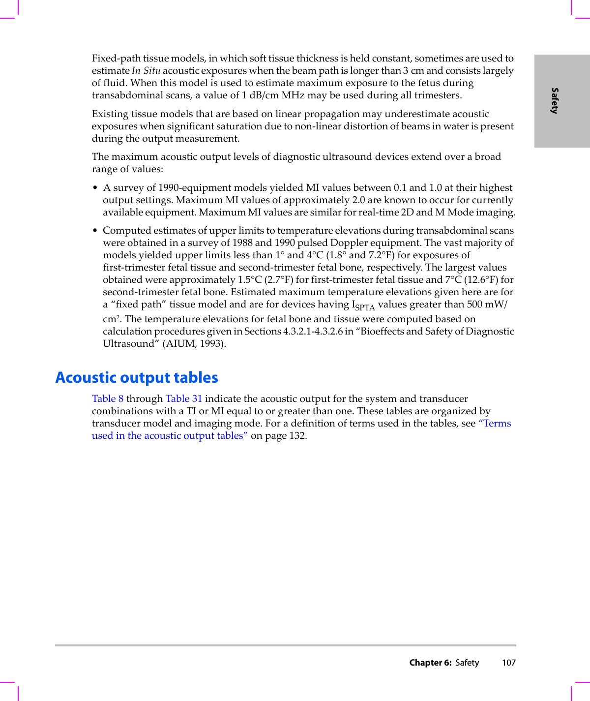
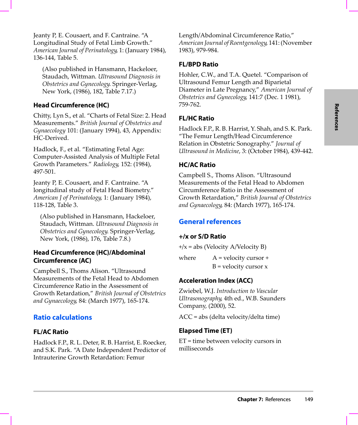
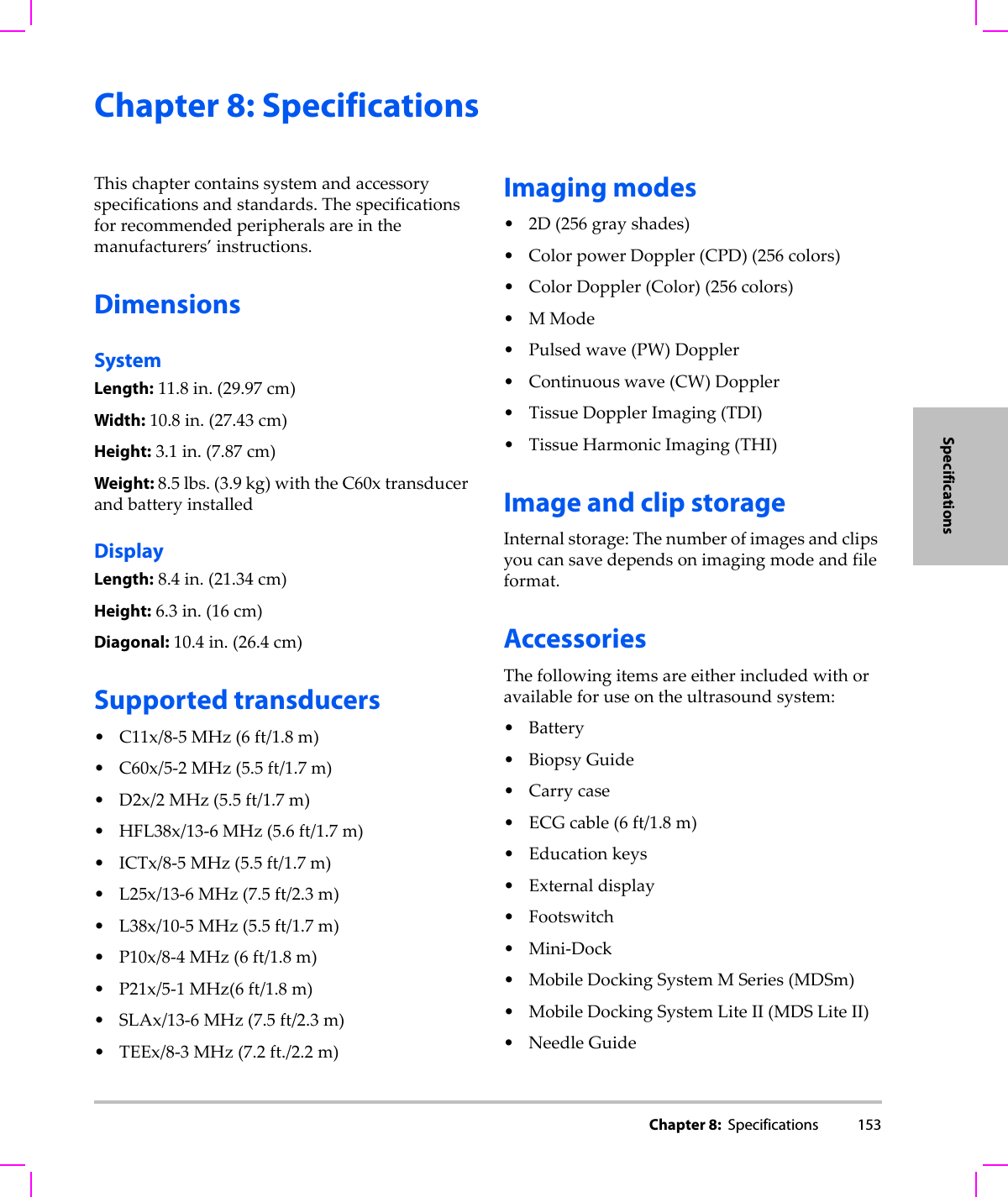
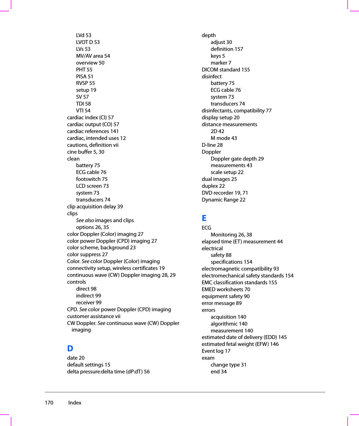
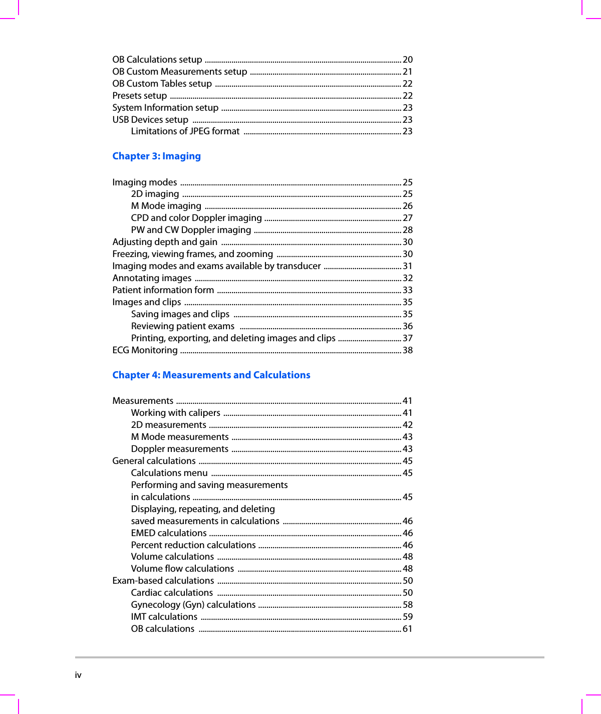
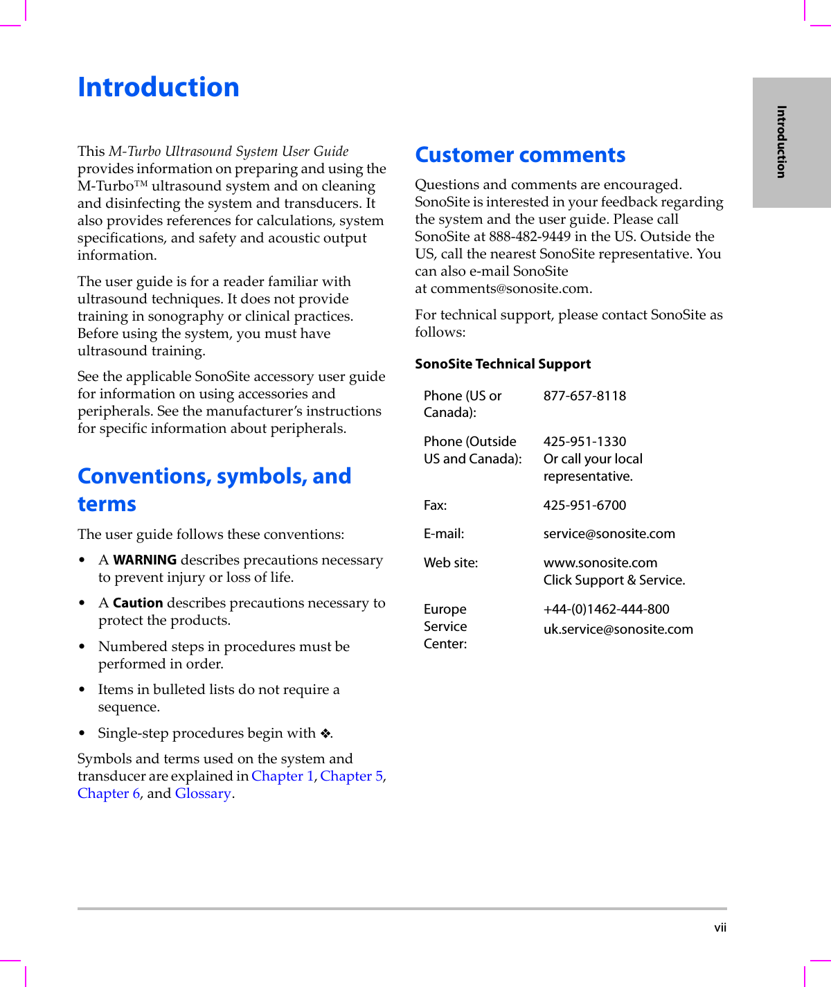
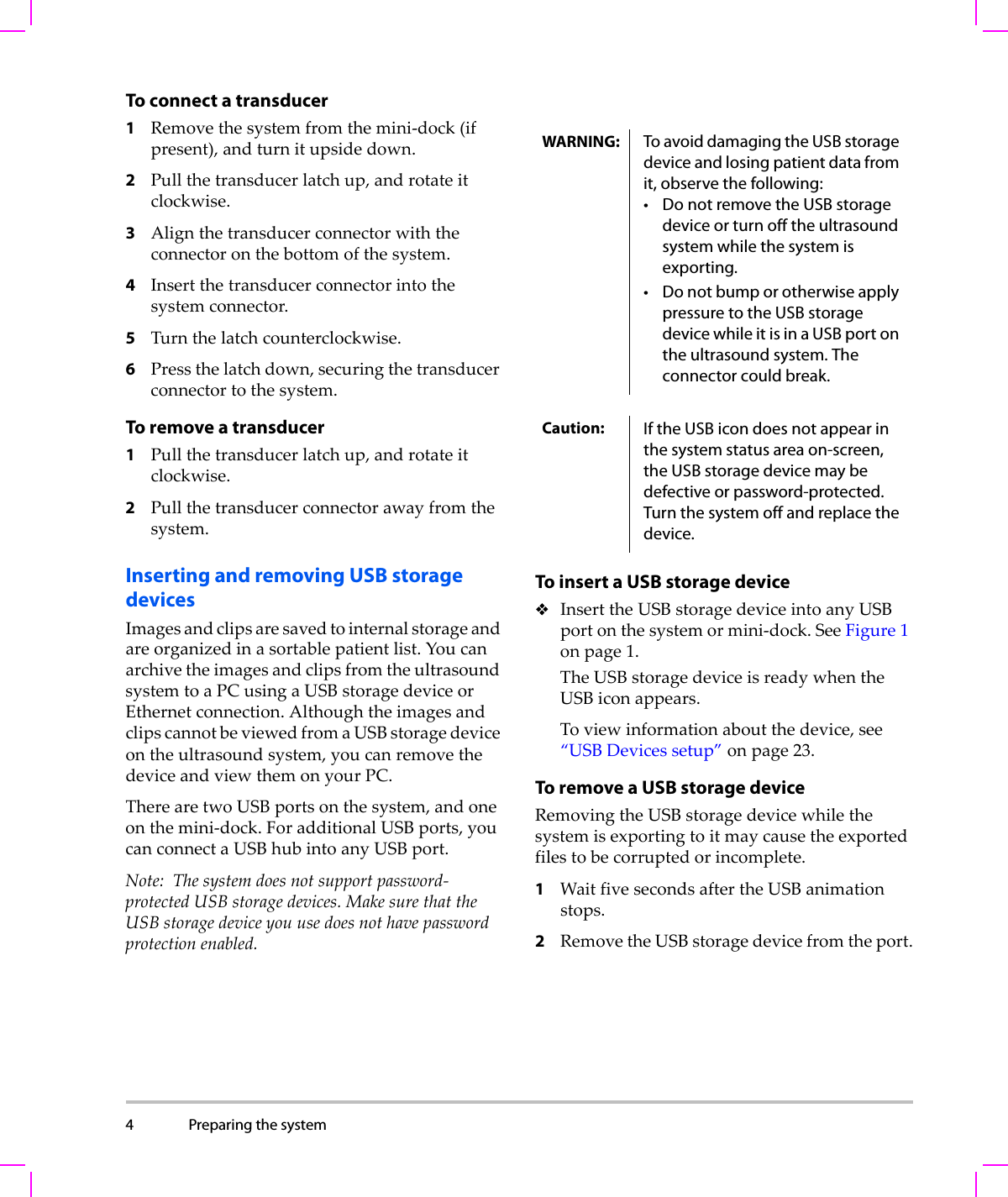
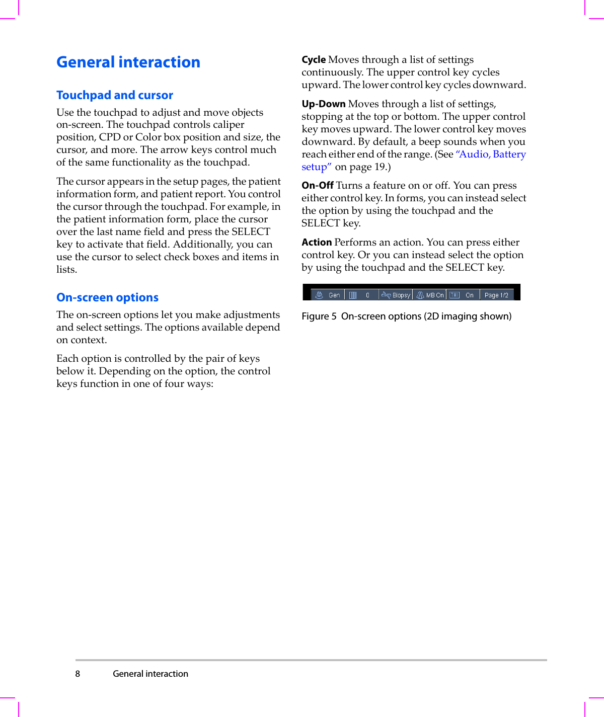
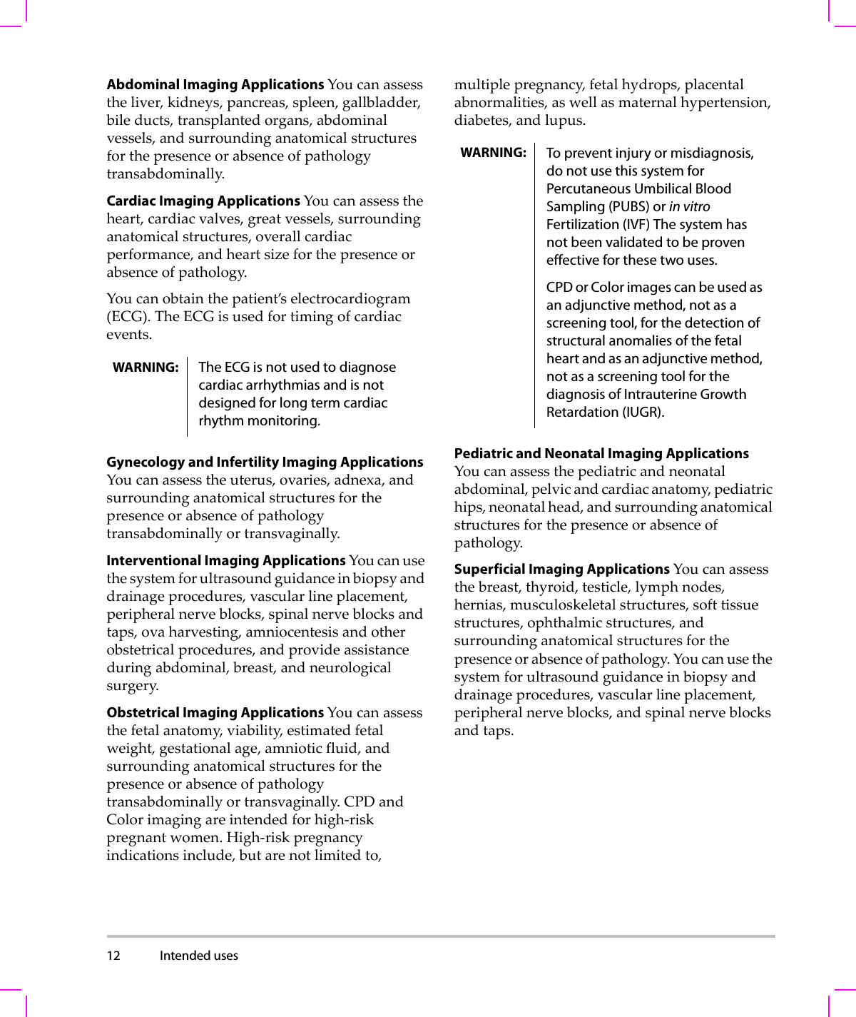
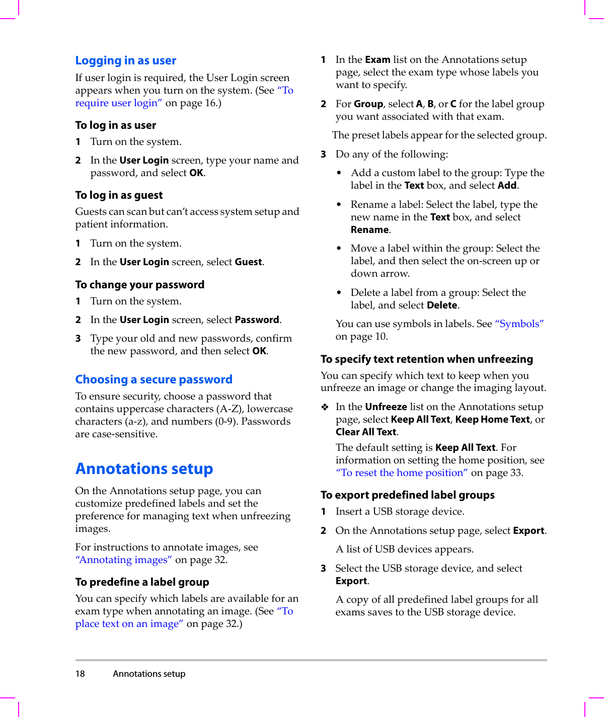
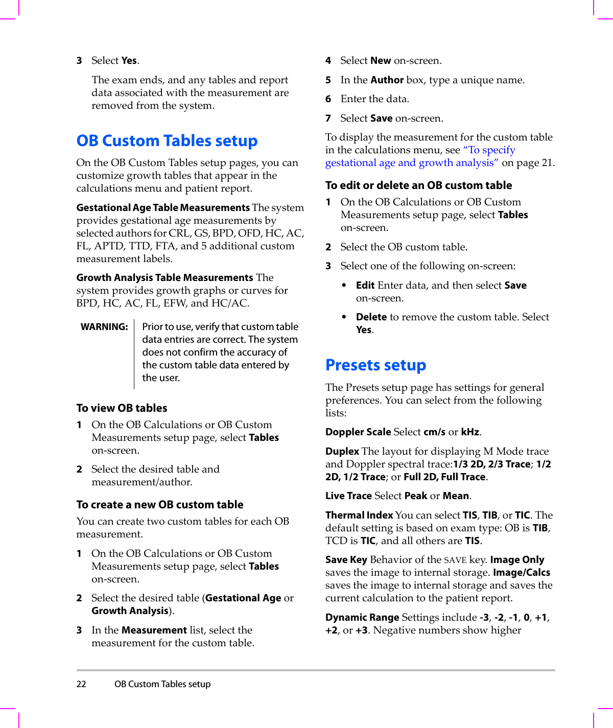
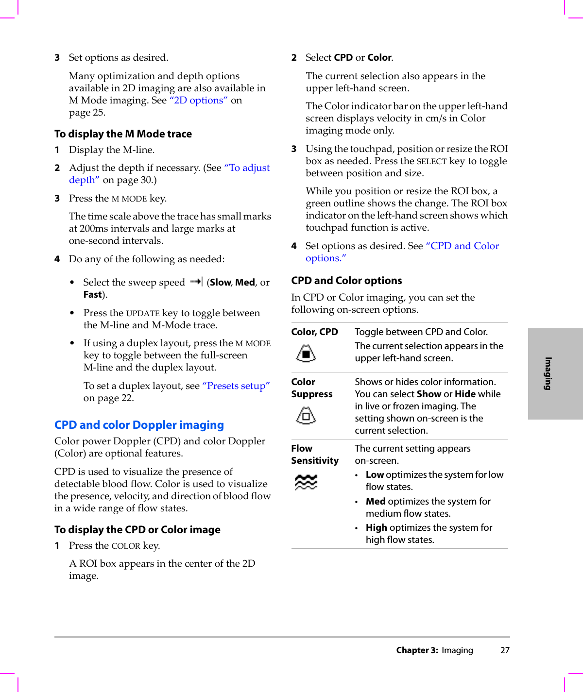
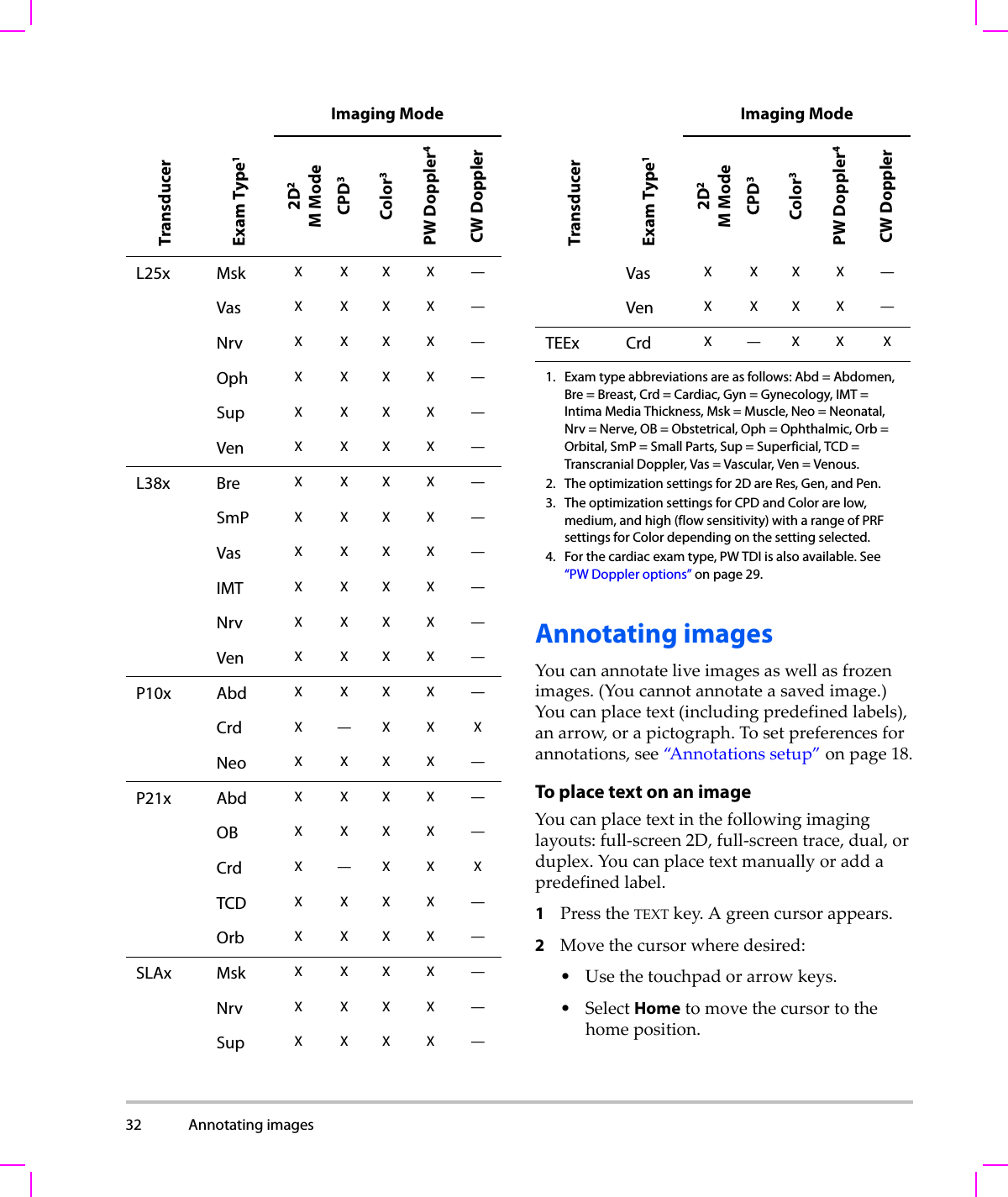
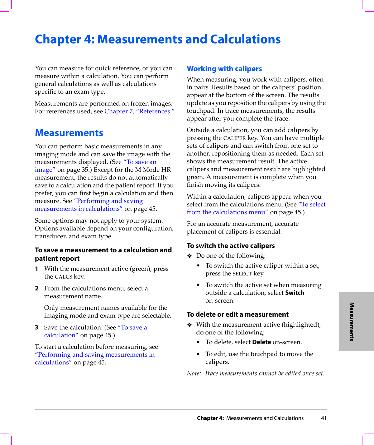
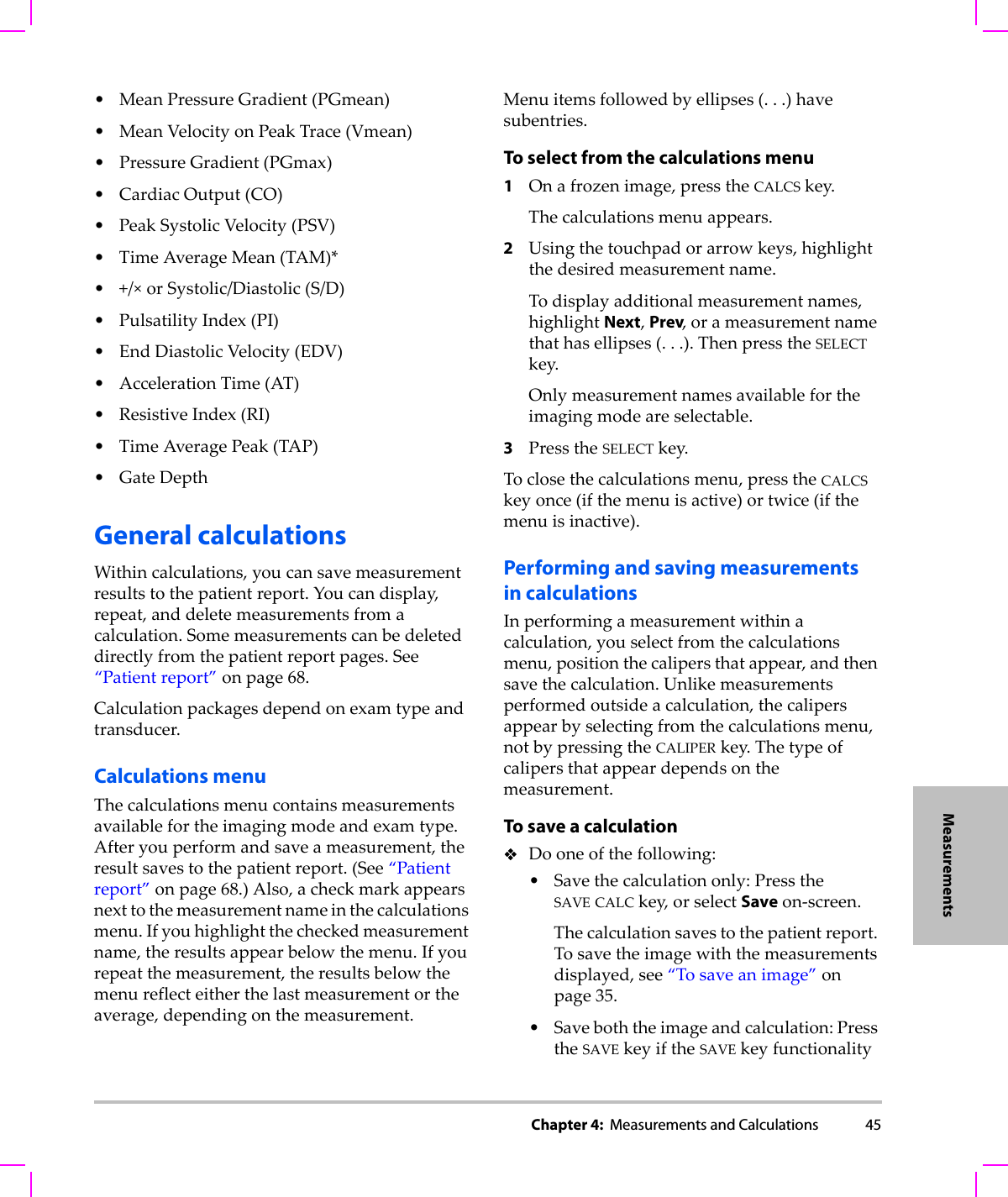
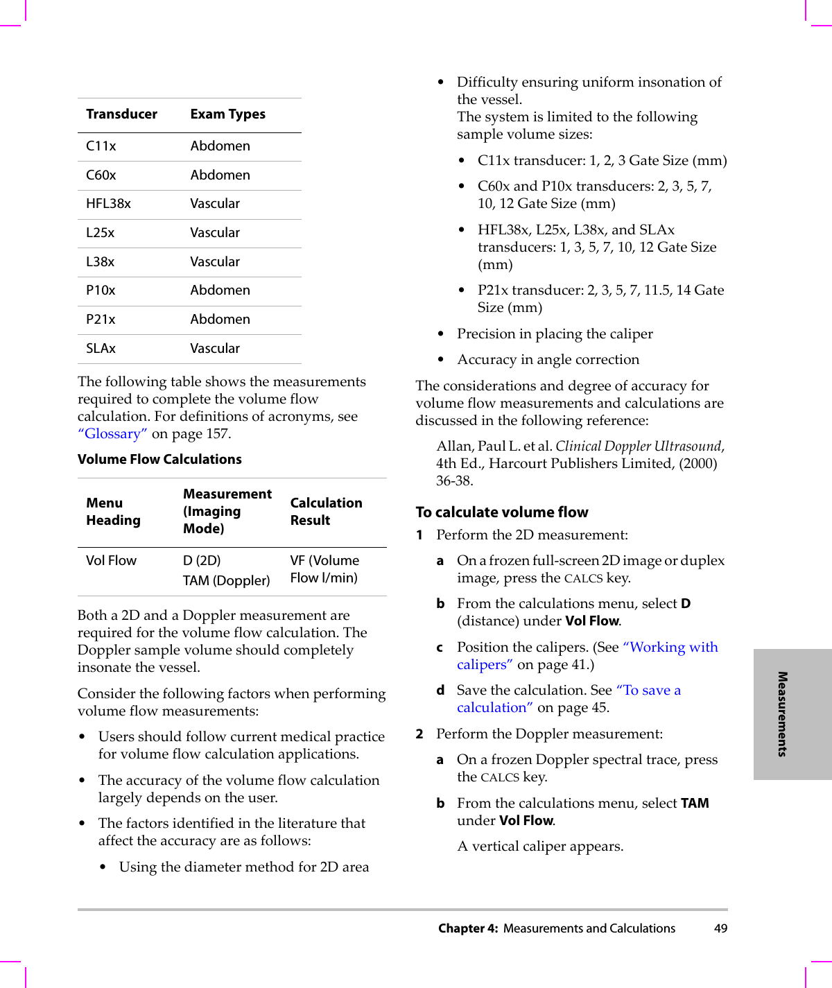
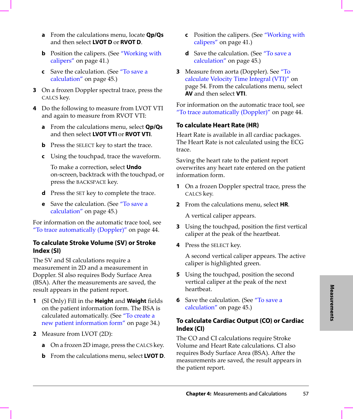
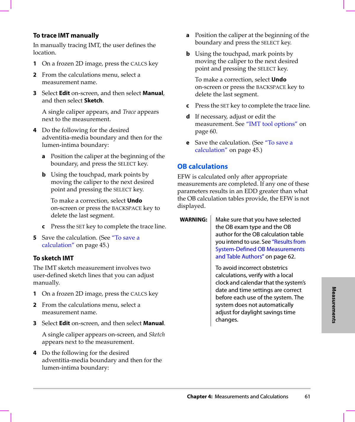
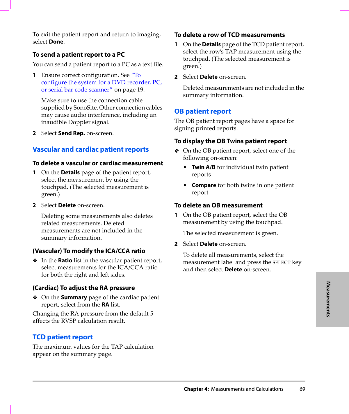
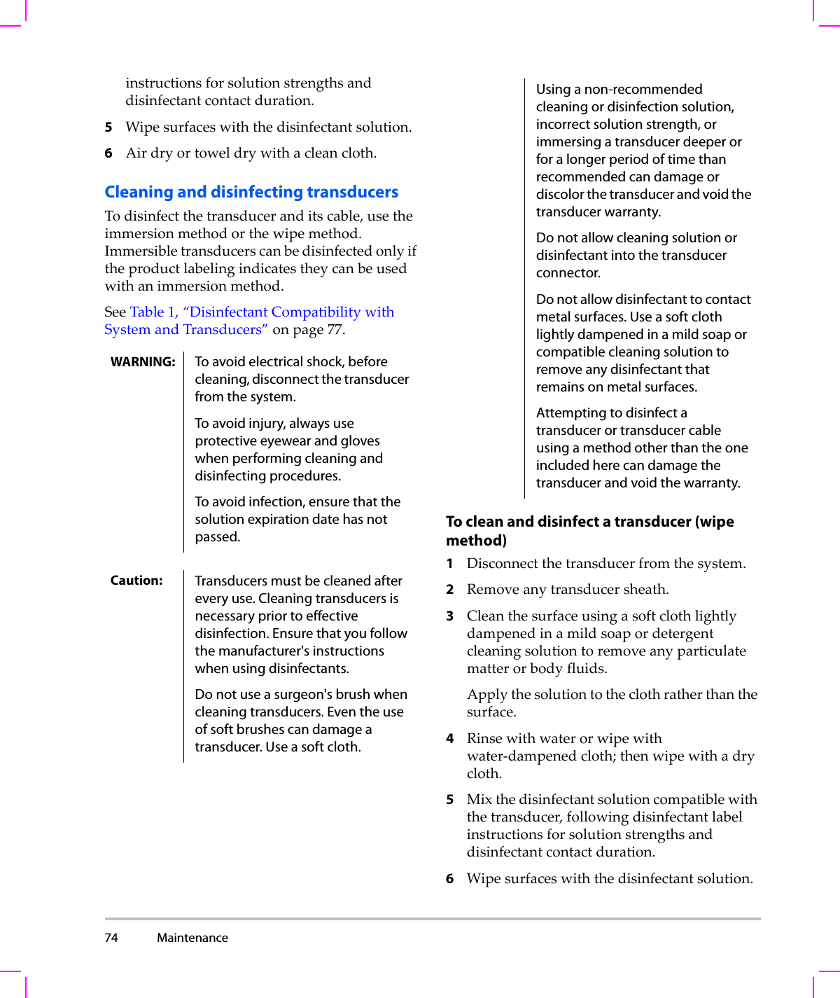
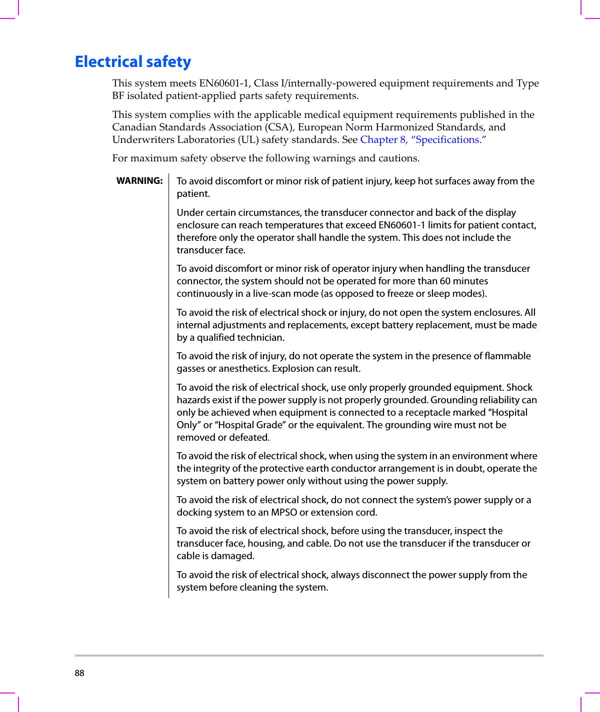
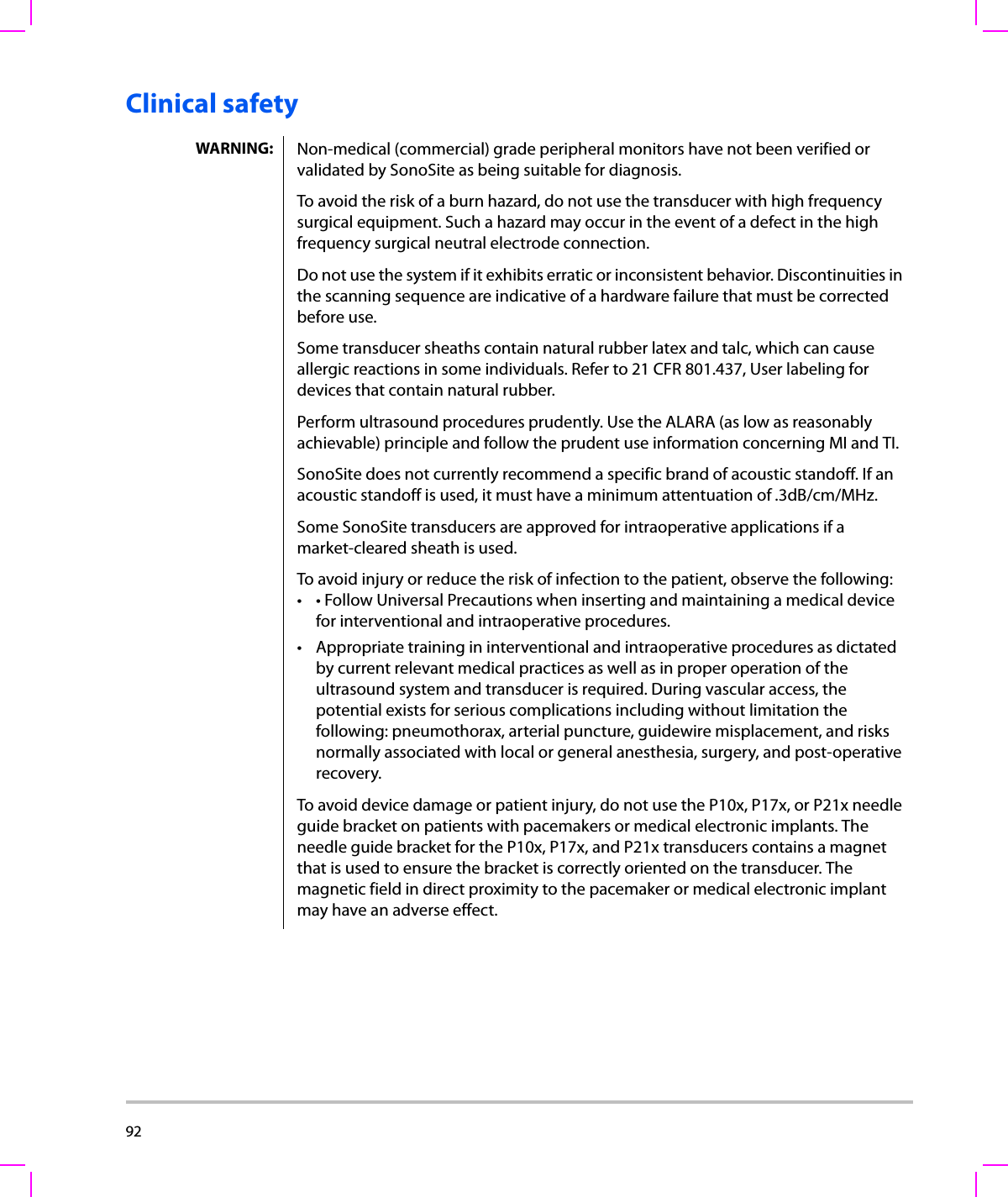
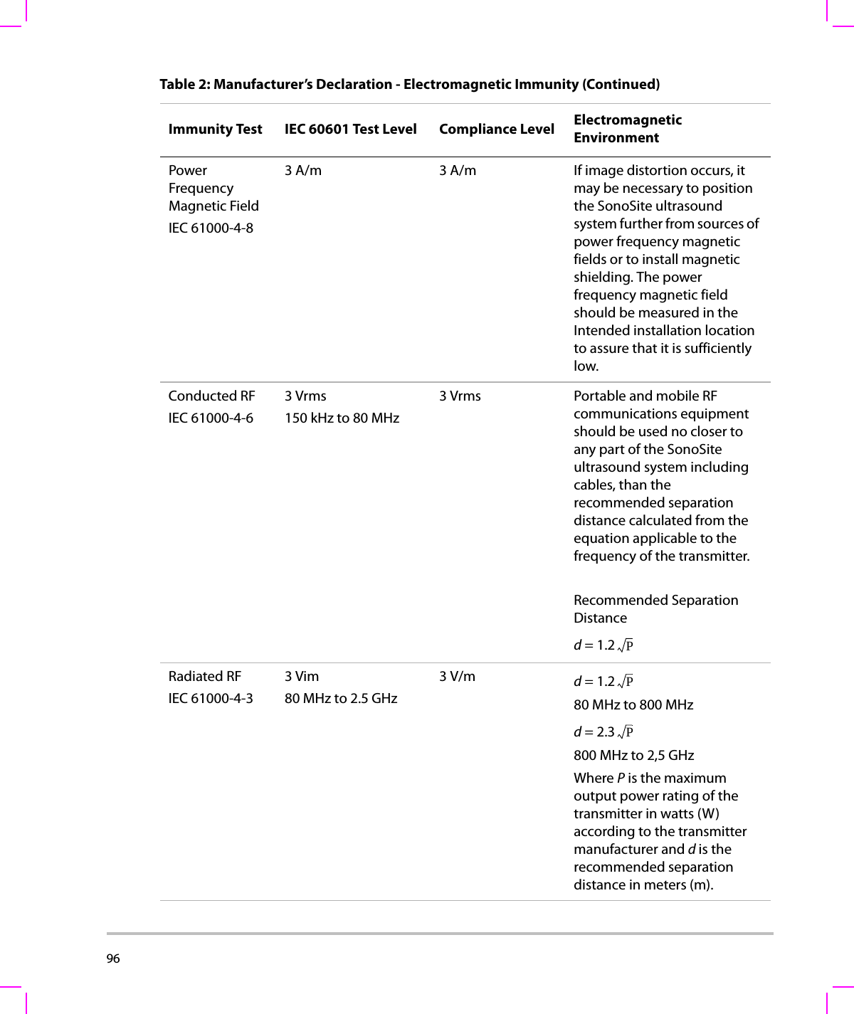
![108 (a) This index is not required for this operating mode; value is <1.(b) This transducer is not intended for transcranial or neonatal cephalic uses.#No data are reported for this operating condition since the global maximum index value is not reported for the reason listed. (Reference Global Maximum Index Value line.)— Data are not applicable for this transducer/mode.Table 8: Transducer Model: C11x/8-5 Operating Mode: CPD/ColorIndex Label M.I.TIS TIBTICScanNon-scanNon-scanAaprt≤1Aaprt>1Global Maximum Index Value (a) (a) — — — 1.2Associated AcousticParameterpr.3 (MPa) #W0(mW) #— —40.50min of [W.3(z1),ITA.3(z1)] (mW) —z1(cm) —zbp (cm) —zsp (cm) #—deq(zsp)(cm) —fc(MHz) ## — — — 4.38Dim of Aaprt X(cm) # — — — 0.36Y(cm) #—— —0.5Other InformationPD (μsec) #PRF (Hz) #pr@PIImax (MPa) #deq@Pllmax (cm) —Focal Length FLx (cm) #—— 1.56FLy (cm) #—— 2.5IPA.3@MImax (W/cm2)#OperatingControl ConditionsControl 1: Mode CPDControl 2: Exam Type VasControl 3: PRF 2841Control 4: Optimization/Depth Med/2.0Control 5: Color Box Position/ SizeTop/Short](https://usermanual.wiki/J-Three-Holding/BU2073J.User-Manual-M-Turbo/User-Guide-1089450-Page-118.png)
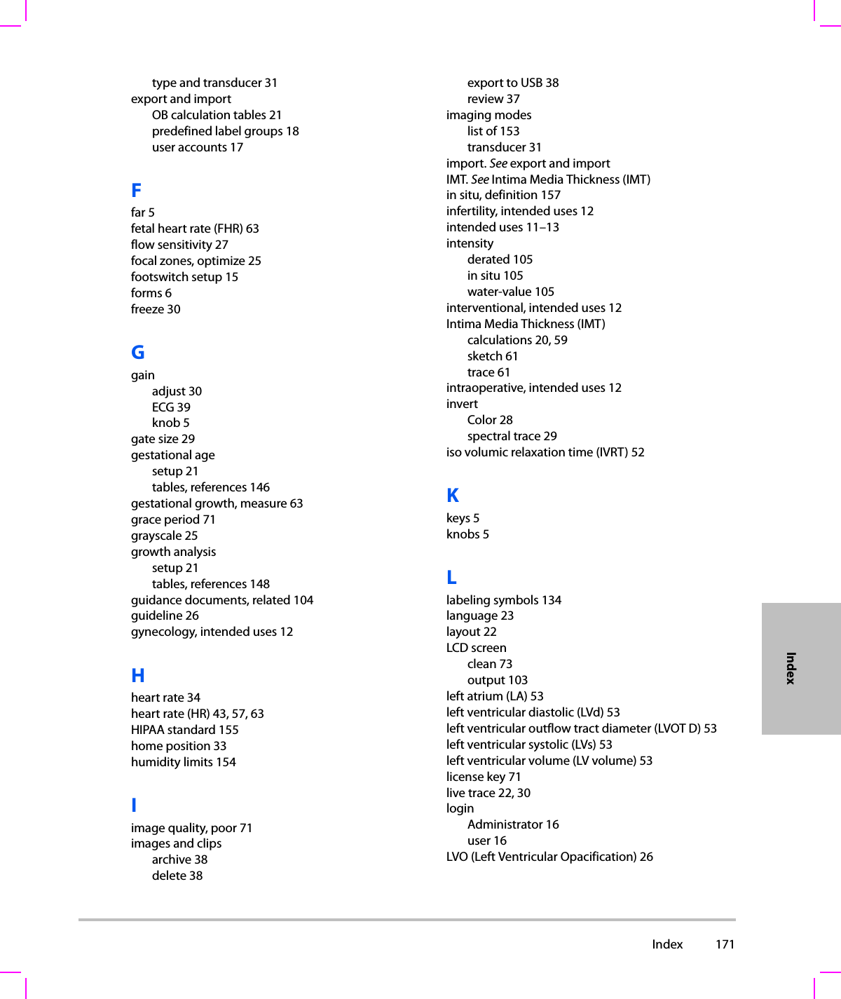
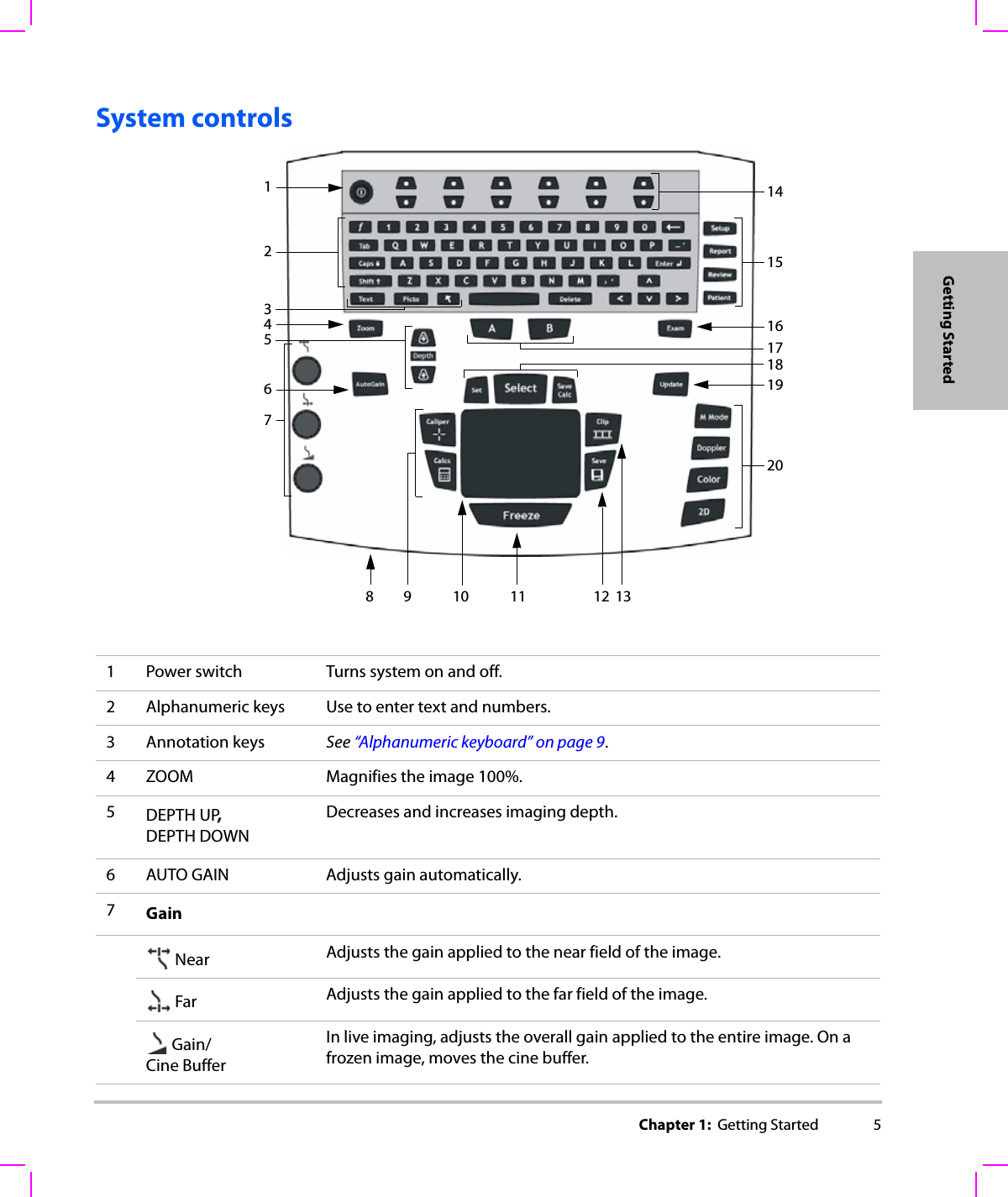
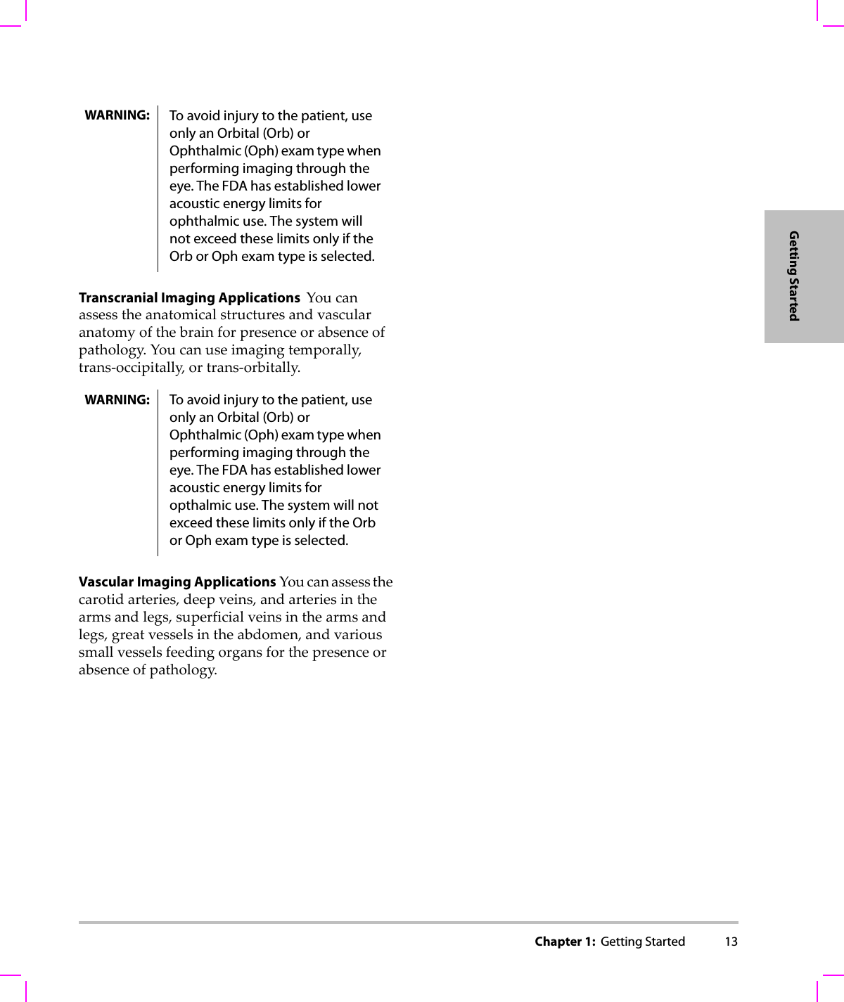
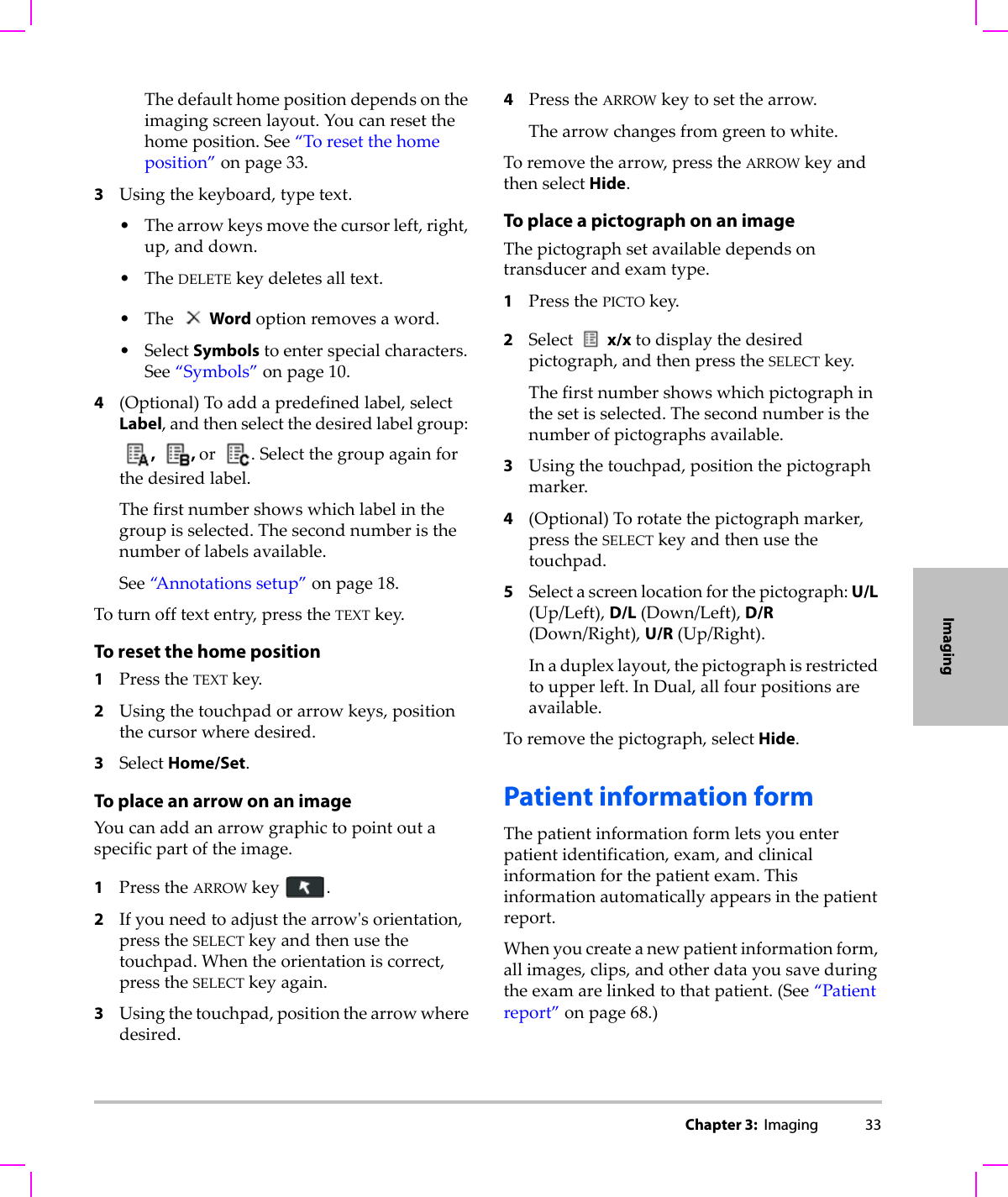
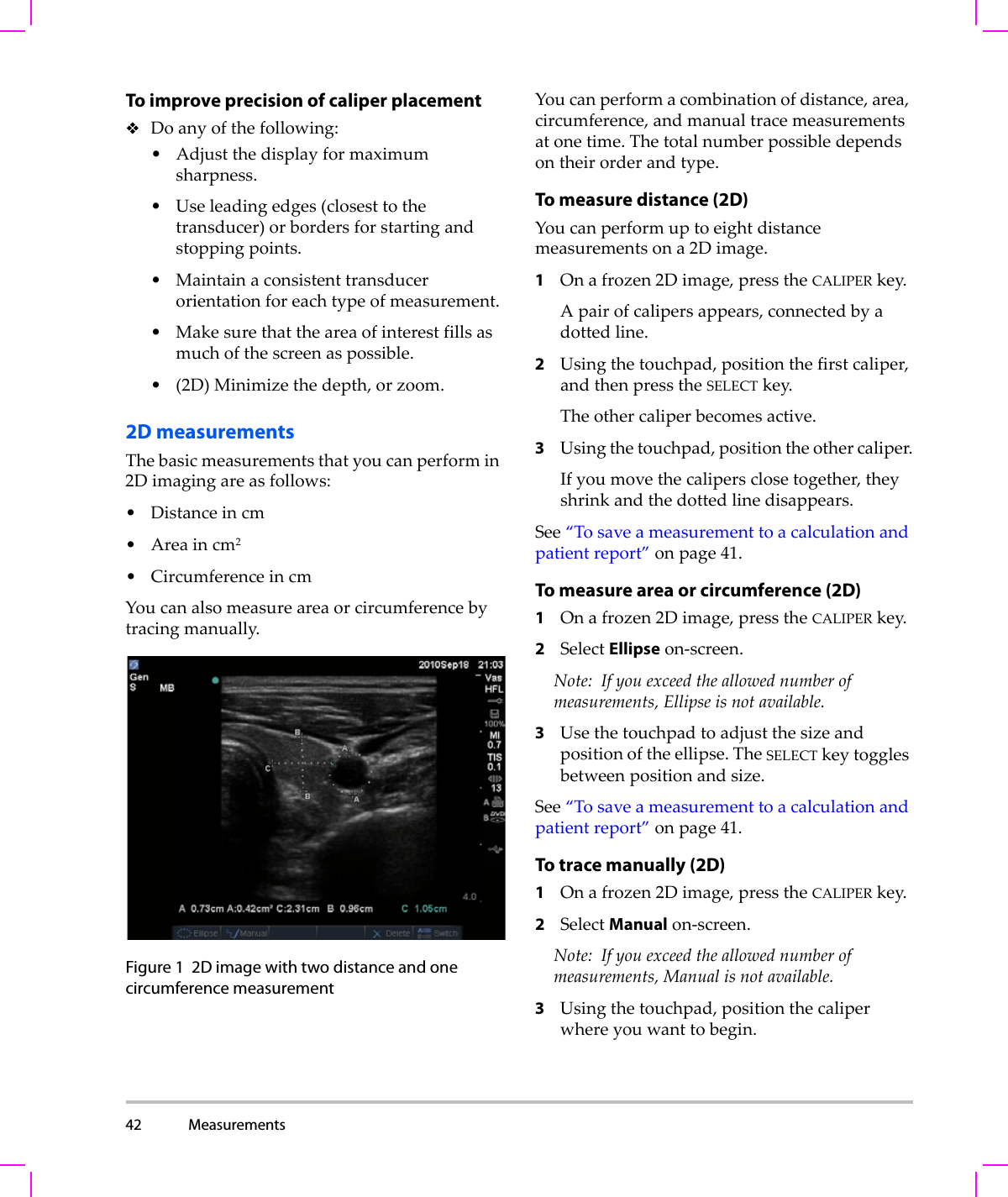
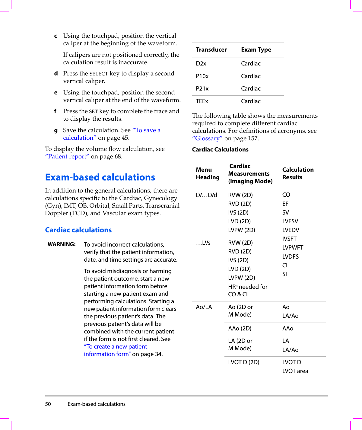
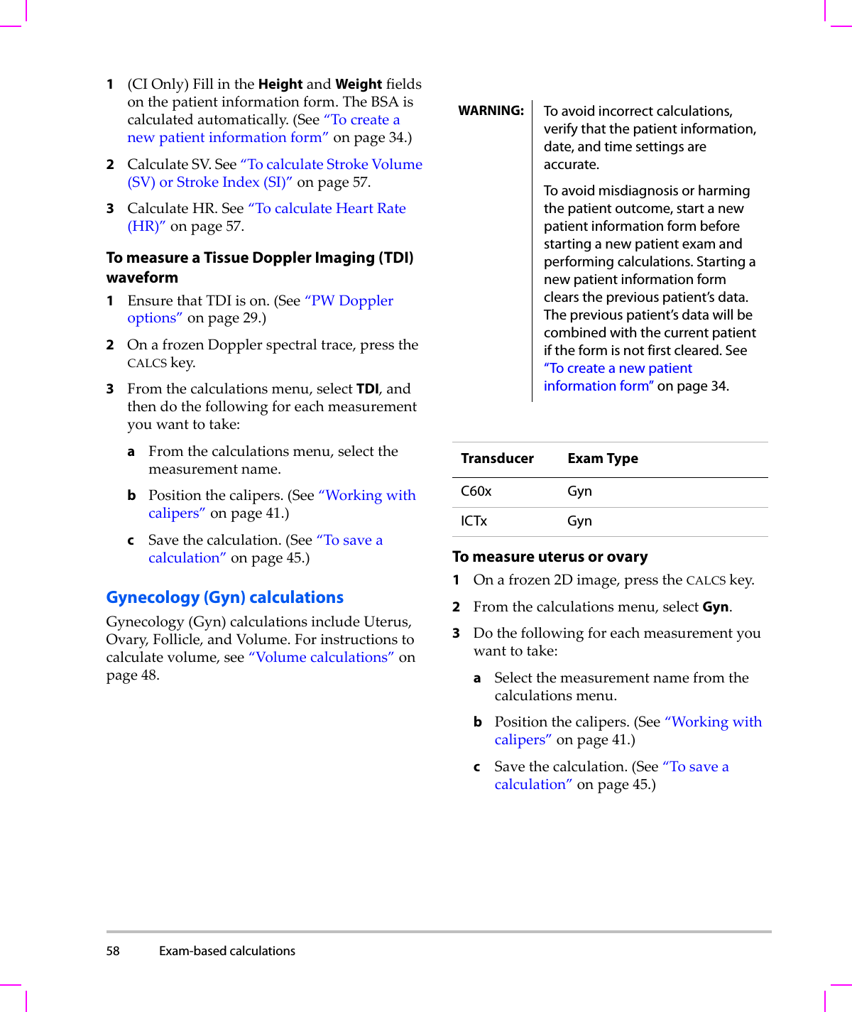
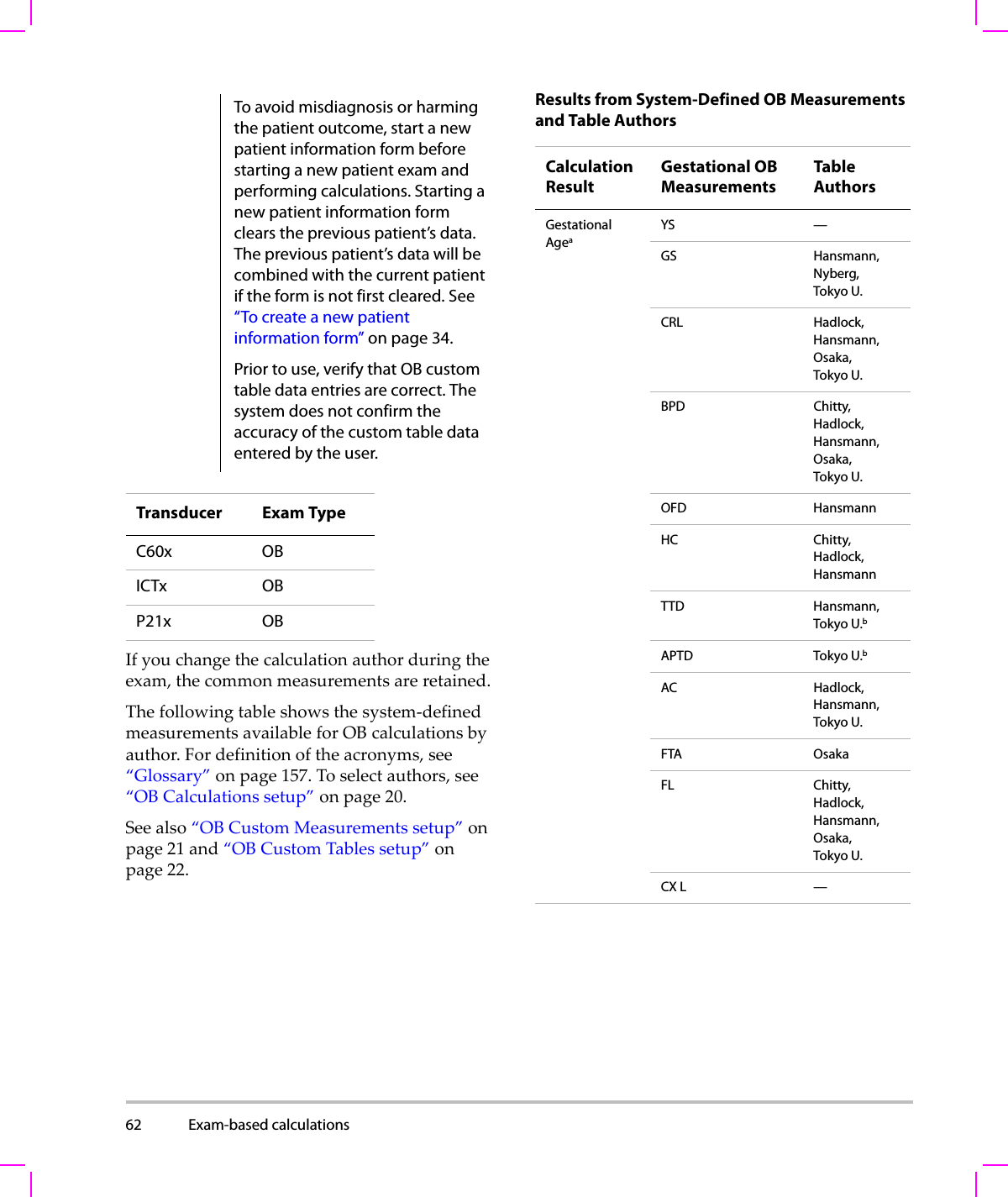
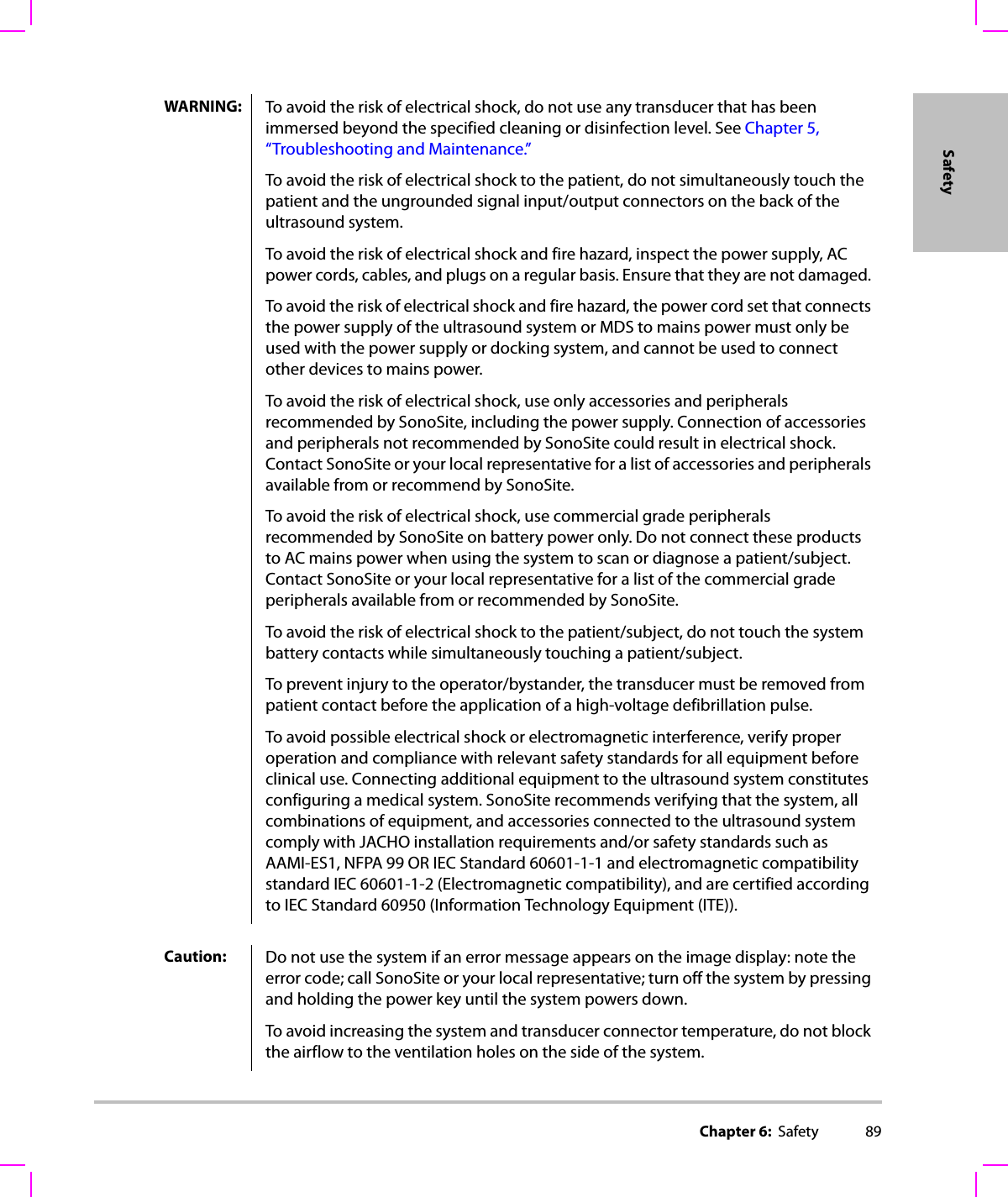
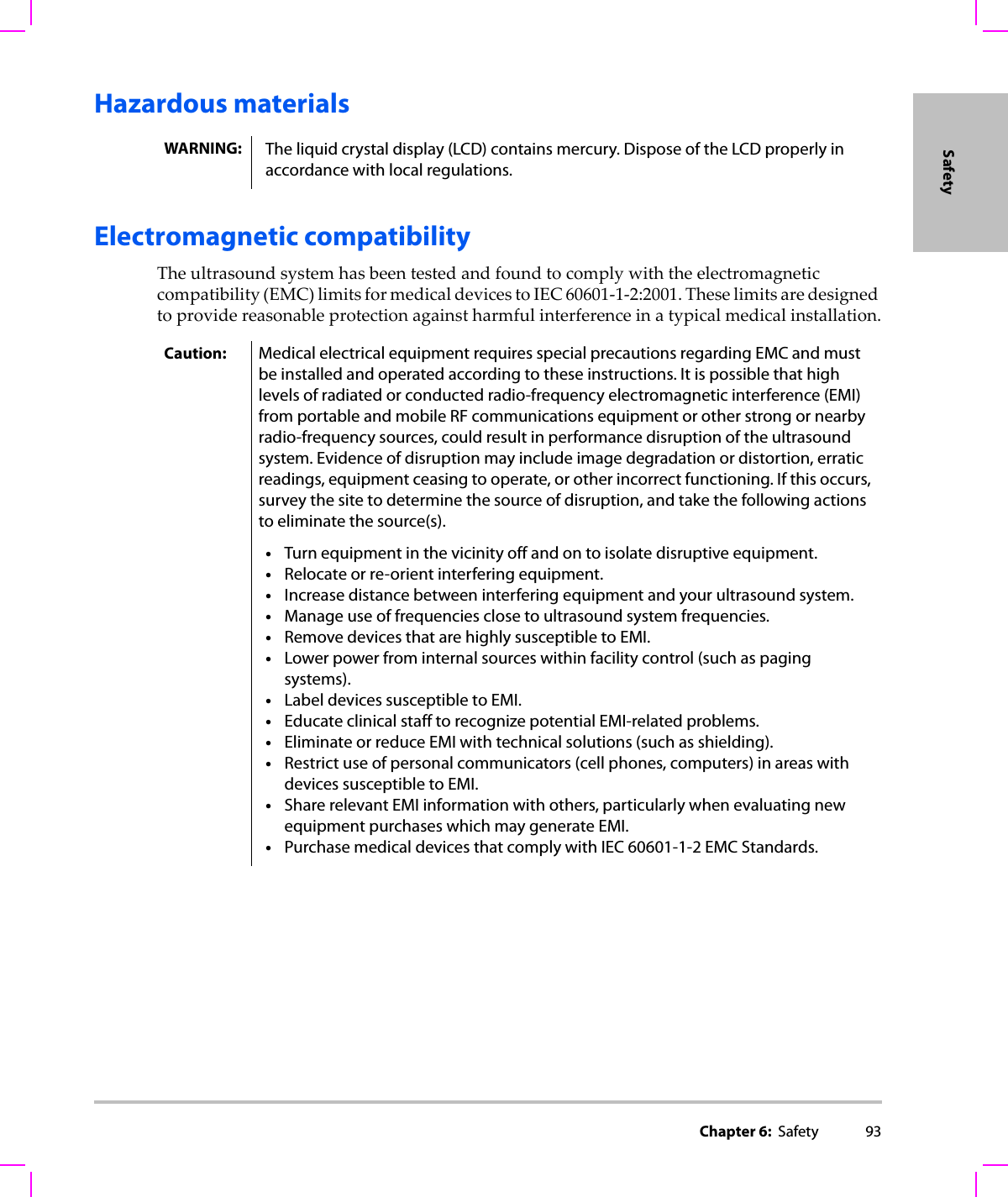
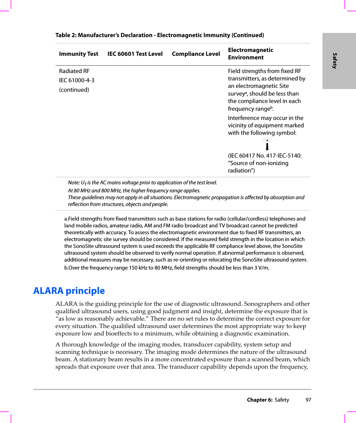
![Chapter 6: Safety 109Safety(a) This index is not required for this operating mode; value is <1.(b) This transducer is not intended for transcranial or neonatal cephalic uses.#No data are reported for this operating condition since the global maximum index value is not reported for the reason listed. (Reference Global Maximum Index Value line.)— Data are not applicable for this transducer/mode.Table 9: Transducer Model: C11x/8-5 Operating Mode: PW DopplerIndex Label M.I.TIS TIBTICScanNon-scanNon-scanAaprt≤1Aaprt>1Global Maximum Index Value (a) — (a) — 1.8 1.7Associated AcousticParameterpr.3 (MPa) #W0(mW) —# 26.29 24.65min of [W.3(z1),ITA.3(z1)] (mW) —z1(cm) —zbp (cm) —zsp (cm) #1.1deq(zsp)(cm) 0.236fc(MHz) # — # — 4.36 4.36Dim of Aaprt X(cm) — # — 0.28 0.2Y(cm) —# — 0.50.5Other InformationPD (μsec) #PRF (Hz) #pr@PIImax (MPa) #deq@Pllmax (cm) 0.226Focal Length FLx (cm) —# — 0.77FLy (cm) —# — 2.5IPA.3@MImax (W/cm2)#OperatingControl ConditionsControl 1: Exam Type Any AnyControl 2: Sample Volume 2 mm 3 mmControl 3: PRF 3906 ≥3906Control 4: Sample Volume Position Zone 1 Zone 0](https://usermanual.wiki/J-Three-Holding/BU2073J.User-Manual-M-Turbo/User-Guide-1089450-Page-119.png)
![110 (a) This index is not required for this operating mode; value is <1.(b) This transducer is not intended for transcranial or neonatal cephalic uses.#No data are reported for this operating condition since the global maximum index value is not reported for the reason listed. (Reference Global Maximum Index Value line.)— Data are not applicable for this transducer/mode.Table 10: Transducer Model: C60x/5-2 Operating Mode: 2DIndex Label M.I.TIS TIBTICScanNon-scanNon-scanAaprt≤1Aaprt>1Global Maximum Index Value 1.0 (a) — — — (b)Associated AcousticParameterpr.3 (MPa) 1.69W0(mW) #— —#min of [W.3(z1),ITA.3(z1)] (mW) —z1(cm) —zbp (cm) —zsp (cm) 4.7 —deq(zsp)(cm) —fc(MHz) 2.84 # — — — #Dim of Aaprt X(cm) #—— — #Y(cm) #—— — #Other InformationPD (μsec) 0.579PRF (Hz) 5440pr@PIImax (MPa) 2.679deq@Pllmax (cm) —Focal Length FLx (cm) #—— #FLy (cm) #—— #IPA.3@MImax (W/cm2)197.7OperatingControl ConditionsControl 1: Exam Type Abd/OBControl 2: Optimization AnyControl 3: Depth 11/13 cmControl 4: THI OnControl 5: MB (Multi Beam) On](https://usermanual.wiki/J-Three-Holding/BU2073J.User-Manual-M-Turbo/User-Guide-1089450-Page-120.png)
![Chapter 6: Safety 111Safety(a) This index is not required for this operating mode; value is <1.(b) This transducer is not intended for transcranial or neonatal cephalic uses.#No data are reported for this operating condition since the global maximum index value is not reported for the reason listed. (Reference Global Maximum Index Value line.)— Data are not applicable for this transducer/mode.Table 11: Transducer Model: C60x/5-2 Operating Mode: MModeIndex Label M.I.TIS TIBTICScanNon-scanNon-scanAaprt≤1Aaprt>1Global Maximum Index Value 1.0 — (a) — (a) (b)Associated AcousticParameterpr.3 (MPa) 1.62W0(mW) —# ##min of [W.3(z1),ITA.3(z1)] (mW) —z1(cm) —zbp (cm) —zsp (cm) 4.7 #deq(zsp)(cm) #fc(MHz) 2.85 — # — # #Dim of Aaprt X(cm) —# — # #Y(cm) —# — # #Other InformationPD (μsec) 0.577PRF (Hz) 800pr@PIImax (MPa) 2.576deq@Pllmax (cm) #Focal Length FLx (cm) —# — #FLy (cm) —# — #IPA.3@MImax (W/cm2)184.3OperatingControl ConditionsControl 1: Exam Type AnyControl 2: Optimization PenControl 3: Depth 7.8 cmControl 4: MB (Multi Beam) Off or On](https://usermanual.wiki/J-Three-Holding/BU2073J.User-Manual-M-Turbo/User-Guide-1089450-Page-121.png)
![112 (a) This index is not required for this operating mode; value is <1.(b) This transducer is not intended for transcranial or neonatal cephalic uses.#No data are reported for this operating condition since the global maximum index value is not reported for the reason listed. (Reference Global Maximum Index Value line.)— Data are not applicable for this transducer/mode.Table 12: Transducer Model: C60x/5-2 Operating Mode: PW DopplerIndex Label M.I.TIS TIBTICScanNon-scanNon-scanAaprt≤1Aaprt>1Global Maximum Index Value (a) — (a) — 3.1 (b)Associated AcousticParameterpr.3 (MPa) #W0(mW) —# 85.64 #min of [W.3(z1),ITA.3(z1)] (mW) —z1(cm) —zbp (cm) —zsp (cm) #1.255deq(zsp)(cm) 0.51fc(MHz) #— # — 2.233#Dim of Aaprt X(cm) —# —0.6552#Y(cm) —# — 1.3 #Other InformationPD (μsec) #PRF (Hz) #pr@PIImax (MPa) #deq@Pllmax (cm) 0.415Focal Length FLx (cm) —# — #FLy (cm) —# — #IPA.3@MImax (W/cm2)#OperatingControl ConditionsControl 1: Exam Type AbdControl 2: PRF AnyControl 3: Sample Volume 12 mmControl 4: Sample Volume Position Zone 1](https://usermanual.wiki/J-Three-Holding/BU2073J.User-Manual-M-Turbo/User-Guide-1089450-Page-122.png)
![Chapter 6: Safety 113Safety(a) This index is not required for this operating mode; value is <1.(b) This transducer is not intended for transcranial or neonatal cephalic uses.#No data are reported for this operating condition since the global maximum index value is not reported for the reason listed. (Reference Global Maximum Index Value line.)— Data are not applicable for this transducer/mode.Table 13: Transducer Model: D2x/2 Operating Mode: CW DopplerIndex Label M.I.TIS TIBTICScanNon-scanNon-scanAaprt≤1Aaprt>1Global Maximum Index Value (a) — (a) — 2.6 (b)Associated AcousticParameterpr.3 (MPa) #W0(mW) —# 90.52 #min of [W.3(z1),ITA.3(z1)] (mW) —z1(cm) —zbp (cm) —zsp (cm) #1.1deq(zsp)(cm) 0.66fc(MHz) #— # — 2.00 #Dim of Aaprt X(cm) —# — 0.8 #Y(cm) —# — 0.4 #Other InformationPD (μsec) #PRF (Hz) #pr@PIImax (MPa) #deq@Pllmax (cm) 0.54Focal Length FLx (cm) —# — #FLy (cm) —# — #IPA.3@MImax (W/cm2)#OperatingControl ConditionsControl 1: Exam Type CrdControl 2: Depth FixedControl 3: Zone Fixed](https://usermanual.wiki/J-Three-Holding/BU2073J.User-Manual-M-Turbo/User-Guide-1089450-Page-123.png)
![114 (a) This index is not required for this operating mode; value is <1.(b) This transducer is not intended for transcranial or neonatal cephalic uses.#No data are reported for this operating condition since the global maximum index value is not reported for the reason listed. (Reference Global Maximum Index Value line.)— Data are not applicable for this transducer/mode.Table 14: Transducer Model: HFL38x/13-6 Operating Mode: CPD/Color Index Label M.I.TIS TIBTICScanNon-scan Non-scanAaprt≤1Aaprt>1Global Maximum Index Value 1.1 1.0 — — — (b)Associated AcousticParameterpr.3 (MPa) 2.556W0(mW) 53.49 — —#min of [W.3(z1),ITA.3(z1)] (mW) —z1(cm) —zbp (cm) —zsp (cm) 1.2 —deq(zsp)(cm) —fc(MHz) 5.328 5.324 — — — #Dim of Aaprt X(cm) 0.44 — — — #Y(cm) 0.4 — — — #Other InformationPD (μsec) 0.525PRF (Hz) 2597pr@PIImax (MPa) 3.187deq@Pllmax (cm) —Focal Length FLx (cm) 1.32 — — #FLy (cm) 2.5 — — #IPA.3@MImax (W/cm2)325.5OperatingControl ConditionsControl 1: Mode Color ColorControl 2: Exam Type Any AnyControl 3: Optimization/Depth/PRF Low/3.3 cm/393Med/2.7 cm/1938Control 4: Color Box Position/Size Any Top/Short](https://usermanual.wiki/J-Three-Holding/BU2073J.User-Manual-M-Turbo/User-Guide-1089450-Page-124.png)
![Chapter 6: Safety 115Safety(a) This index is not required for this operating mode; value is <1.(b) This transducer is not intended for transcranial or neonatal cephalic uses.#No data are reported for this operating condition since the global maximum index value is not reported for the reason listed. (Reference Global Maximum Index Value line.)— Data are not applicable for this transducer/mode.Table 15: Transducer Model: HFL38x/13-6 Operating Mode: PW DopplerIndex Label M.I.TIS TIBTICScanNon-scanNon-scanAaprt≤1Aaprt>1Global Maximum Index Value 1.0 — 1.2 — 2.2 (b)Associated AcousticParameterpr.3 (MPa) 2.37W0(mW) — 46.55 46.55 #min of [W.3(z1),ITA.3(z1)] (mW) —z1(cm) —zbp (cm) —zsp (cm) 0.9 1.1deq(zsp)(cm) 0.33fc(MHz) 5.32 — 5.33 — 5.33 #Dim of Aaprt X(cm) —1.04 — 1.04 #Y(cm) — 0.4 — 0.4 #Other InformationPD (μsec) 1.29PRF (Hz) 1008pr@PIImax (MPa) 2.404deq@Pllmax (cm) 0.46Focal Length FLx (cm) —3.72 — #FLy (cm) —2.5 — #IPA.3@MImax (W/cm2)323.35OperatingControl ConditionsControl 1: Exam Type Bre/VasSmP/IMTVas/Ven/IMTVas/Ven/IMTControl 2: Sample Volume 1 mm 12 mm 12 mmControl 3: PRF 1008 10417 10417Control 4: Sample Volume Position Zone 2 Zone 7 Zone 7](https://usermanual.wiki/J-Three-Holding/BU2073J.User-Manual-M-Turbo/User-Guide-1089450-Page-125.png)
![116 (a) This index is not required for this operating mode; value is <1.(b) This transducer is not intended for transcranial or neonatal cephalic uses.#No data are reported for this operating condition since the global maximum index value is not reported for the reason listed. (Reference Global Maximum Index Value line.)— Data are not applicable for this transducer/mode.Table 16: Transducer Model: ICTx/8-5 Operating Mode: PW DopplerIndex Label M.I.TIS TIBTICScanNon-scanNon-scanAaprt≤1Aaprt>1Global Maximum Index Value (a) — (a) — 1.2 (a)Associated AcousticParameterpr.3 (MPa) #W0(mW) —# 16.348 #min of [W.3(z1),ITA.3(z1)] (mW) —z1(cm) —zbp (cm) —zsp (cm) #1.6deq(zsp)(cm) 0.192fc(MHz) # — # — 4.36 #Dim of Aaprt X(cm) —# — 0.6 #Y(cm) —# — 0.5 #Other InformationPD (μsec) #PRF (Hz) #pr@PIImax (MPa) #deq@Pllmax (cm) 0.187Focal Length FLx (cm) —# — #FLy (cm) —# — #IPA.3@MImax (W/cm2)#OperatingControl ConditionsControl 1: Exam Type AnyControl 2: Sample Volume 3 mmControl 3: PRF AnyControl 4: Sample Volume Position Zone 1](https://usermanual.wiki/J-Three-Holding/BU2073J.User-Manual-M-Turbo/User-Guide-1089450-Page-126.png)
![Chapter 6: Safety 117Safety(a) This index is not required for this operating mode; value is <1.(b) This transducer is not intended for transcranial or neonatal cephalic uses.#No data are reported for this operating condition since the global maximum index value is not reported for the reason listed. (Reference Global Maximum Index Value line.)— Data are not applicable for this transducer/mode.Table 17: Transducer Model L25x/13-6 Operating Mode: PW DopplerIndex Label M.I.TIS TIBTICScanNon-scanNon-scanAaprt≤1Aaprt>1Global Maximum Index Value (a) — (a) — 1.6 (b)Associated AcousticParameterpr.3 (MPa) #W0(mW) —# 14.02 #min of [W.3(z1),ITA.3(z1)] (mW) —z1(cm) —zbp (cm) —zsp (cm) #0.6deq(zsp)(cm) 0.155fc(MHz) #— # — 6.00 #Dim of Aaprt X(cm) —# — 0.16#Y(cm) —# — 0.3 #Other InformationPD (μsec) #PRF (Hz) #pr@PIImax (MPa) #deq@Pllmax (cm) 0.1549Focal Length FLx (cm) —# — #FLy (cm) —# — #IPA.3@MImax (W/cm2)#OperatingControl ConditionsControl 1: Exam Type Vas/Nrv/VenControl 2: Sample Volume 12 mmControl 3: PRF 20833Control 4: Sample Volume Position Zone 0](https://usermanual.wiki/J-Three-Holding/BU2073J.User-Manual-M-Turbo/User-Guide-1089450-Page-127.png)
![118 (a) This index is not required for this operating mode; value is <1.(b) This transducer is not intended for transcranial or neonatal cephalic uses.#No data are reported for this operating condition since the global maximum index value is not reported for the reason listed. (Reference Global Maximum Index Value line.)— Data are not applicable for this transducer/mode.Table 18: Transducer Model: L38x/10-5 Operating Mode: CPD/Color Index Label M.I.TIS TIBTICScanNon-scanNon-scanAaprt≤1Aaprt>1Global Maximum Index Value 1.3 1.0 — — — (b)Associated AcousticParameterpr.3 (MPa) 2.89W0(mW) 64.88 — —#min of [W.3(z1),ITA.3(z1)] (mW) —z1(cm) —zbp (cm) —zsp (cm) 1.1 —deq(zsp)(cm) —fc(MHz) 4.91 4.91 — — — #Dim of Aaprt X(cm) 0.54 — — — #Y(cm) 0.4 — — — #Other InformationPD (μsec) 0.529PRF (Hz) 9547pr@PIImax (MPa) 3.48deq@Pllmax (cm) —Focal Length FLx (cm) 1.5 — — #FLy (cm) 2.5 — — #IPA.3@MImax (W/cm2)439.3OperatingControl ConditionsControl 1: Mode Color CPDControl 2: Exam Type Any BreControl 3: PRF 331 2137Control 4: Optimization/Depth Any/3.1 Med/3.1Control 5: Color Box Position/Size Any Def/Def/Def](https://usermanual.wiki/J-Three-Holding/BU2073J.User-Manual-M-Turbo/User-Guide-1089450-Page-128.png)
![Chapter 6: Safety 119Safety(a) This index is not required for this operating mode; value is <1.(b) This transducer is not intended for transcranial or neonatal cephalic uses.#No data are reported for this operating condition since the global maximum index value is not reported for the reason listed. (Reference Global Maximum Index Value line.)— Data are not applicable for this transducer/mode.Table 19: Transducer Model: L38x/10-5 Operating Mode: PW DopplerIndex Label M.I.TIS TIBTICScanNon-scanNon-scanAaprt≤1Aaprt>1Global Maximum Index Value 1.04 — 2.0 — 2.6 (b)Associated AcousticParameterpr.3 (MPa) 2.345W0(mW) —84.94 84.94 #min of [W.3(z1),ITA.3(z1)] (mW) —z1(cm) —zbp (cm) —zsp (cm) 0.8 1.3deq(zsp)(cm) 0.4685fc(MHz) 5.01 — 5.05 — 5.05 #Dim of Aaprt X(cm) — 1.80 — 1.80 #Y(cm) — 0.4 — 0.4 #Other InformationPD (μsec) 1.29PRF (Hz) 1008pr@PIImax (MPa) 2.693deq@Pllmax (cm) 0.2533Focal Length FLx (cm) —5.54 — #FLy (cm) —2.5 — #IPA.3@MImax (W/cm2)284.5OperatingControl ConditionsControl 1: Exam Type Any Vas VasControl 2: Sample Volume 1 mm 12 mm 12 mmControl 3: PRF 1008 Any AnyControl 4: Sample Volume Position Zone 0 (top) Zone 7 Zone 7](https://usermanual.wiki/J-Three-Holding/BU2073J.User-Manual-M-Turbo/User-Guide-1089450-Page-129.png)
![120 (a) This index is not required for this operating mode; value is <1.(b) This transducer is not intended for transcranial or neonatal cephalic uses.#No data are reported for this operating condition since the global maximum index value is not reported for the reason listed. (Reference Global Maximum Index Value line.)— Data are not applicable for this transducer/mode.Table 20: Transducer Model: P10x/8-4 Operating Mode: 2D ModeIndex Label M.I.TIS TIBTICScanNon-scanNon-scanAaprt≤1Aaprt>1Global Maximum Index Value (a) (a) — — — 1.0Associated AcousticParameterpr.3 (MPa) #W0(mW) #— —35.24min of [W.3(z1),ITA.3(z1)] (mW) —z1(cm) —zbp (cm) —zsp (cm) #—deq(zsp)(cm) —fc(MHz) ## — — — 4.84Dim of Aaprt X(cm) # — — — 0.416Y(cm) #—— —0.7Other InformationPD (μsec) #PRF (Hz) #pr@PIImax (MPa) #deq@Pllmax (cm) —Focal Length FLx (cm) #—— 1.67FLy (cm) #—— 5.0IPA.3@MImax (W/cm2)#OperatingControl ConditionsControl 1: Exam Type NeoControl 2: Optimization GenControl 3: Depth 2.0Control 4: MB/SonoHD Off/Off](https://usermanual.wiki/J-Three-Holding/BU2073J.User-Manual-M-Turbo/User-Guide-1089450-Page-130.png)
![Chapter 6: Safety 121Safety(a) This index is not required for this operating mode; value is <1.(b) This transducer is not intended for transcranial or neonatal cephalic uses.#No data are reported for this operating condition since the global maximum index value is not reported for the reason listed. (Reference Global Maximum Index Value line.)— Data are not applicable for this transducer/mode.Table 21: Transducer Model: P10x/8-4 Operating Mode: ColorIndex Label M.I.TIS TIBTICScanNon-scanNon-scanAaprt≤1Aaprt>1Global Maximum Index Value 1.0 (a) — — — 1.3Associated AcousticParameterpr.3 (MPa) 2.02W0(mW) #— — 41.38min of [W.3(z1),ITA.3(z1)] (mW) —z1(cm) —zbp (cm) —zsp (cm) 2.4 —deq(zsp)(cm) —fc(MHz) 3.90 # — — — 3.91Dim of Aaprt X(cm) #— — —0.608Y(cm) #— — —0.7Other InformationPD (μsec) 0.70PRF (Hz) 2772pr@PIImax (MPa) 2.80deq@Pllmax (cm) —Focal Length FLx (cm) #— — 2.48FLy (cm) #— — 5.0IPA.3@MImax (W/cm2)252OperatingControl ConditionsControl 1: Mode Color ColorControl 2: Exam Type Neo AbdControl 3: Optimization/Depth/PRF Low/3.7/772Med/2.0/2315Control 4: Color Box Pos/Size Any/TallShort/Narrow](https://usermanual.wiki/J-Three-Holding/BU2073J.User-Manual-M-Turbo/User-Guide-1089450-Page-131.png)
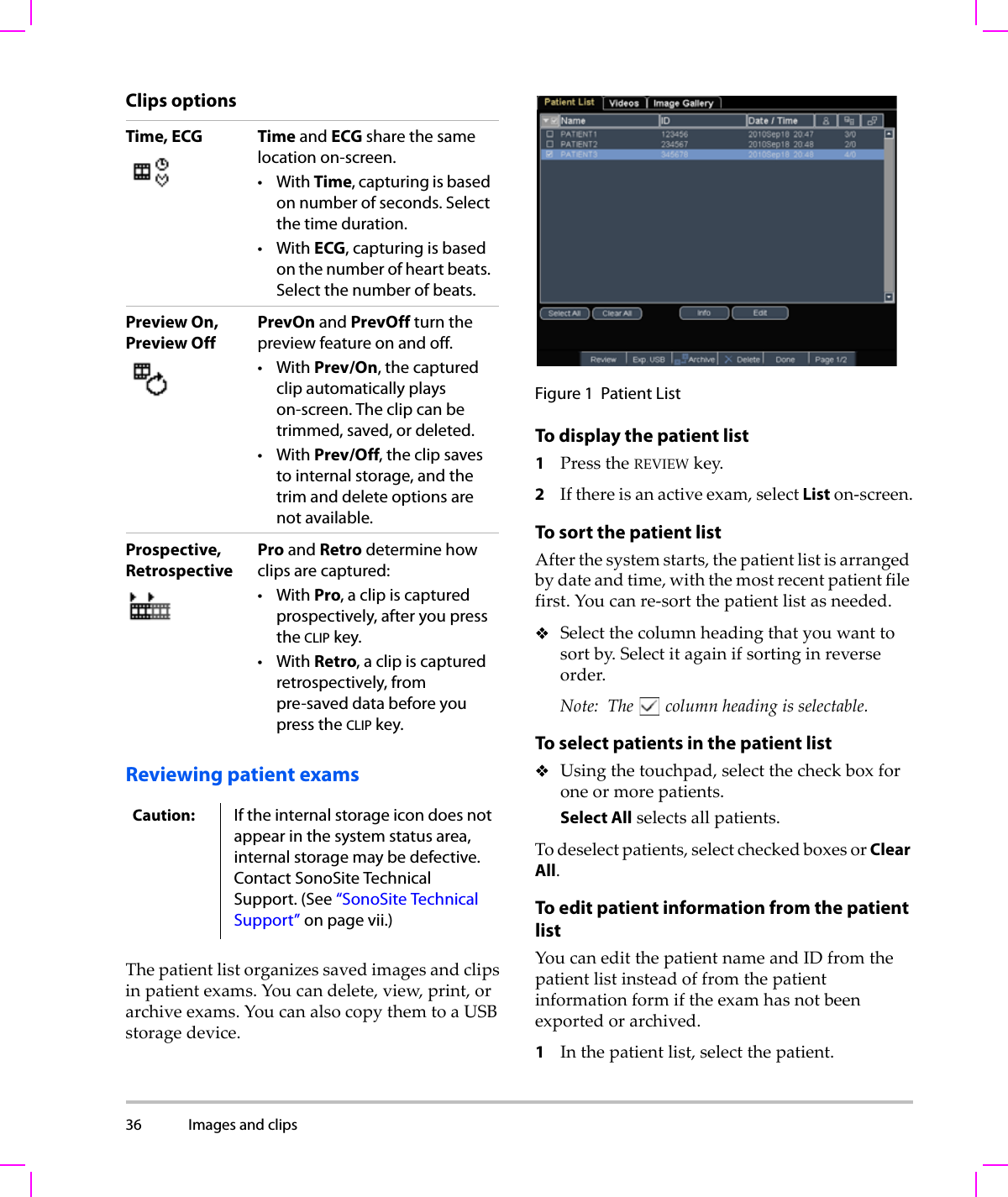
![122 (a) This index is not required for this operating mode; value is <1.(b) This transducer is not intended for transcranial or neonatal cephalic uses.#No data are reported for this operating condition since the global maximum index value is not reported for the reason listed. (Reference Global Maximum Index Value line.)— Data are not applicable for this transducer/mode.Table 22: Transducer Model: P10x/8-4 Operating Mode: PW DopplerIndex Label M.I.TIS TIBTICScanNon-scanNon-scanAaprt≤1Aaprt>1Global Maximum Index Value 1.0 — 1.2 — 2.0 1.8Associated AcousticParameterpr.3 (MPa) 2.03W0(mW) — 36.25 34.4 31.5min of [W.3(z1),ITA.3(z1)] (mW) —z1(cm) —zbp (cm) —zsp (cm) 2.1 0.8deq(zsp)(cm) 0.32fc(MHz) 3.87 — 6.86 — 3.84 3.86Dim of Aaprt X(cm) — 0.992 — 0.416 .224Y(cm) — 0.7 — 0.7 0.7Other InformationPD (μsec) 1.28PRF (Hz) 1563pr@PIImax (MPa) 2.70deq@Pllmax (cm) 0.25Focal Length FLx (cm) —6.74 — 0.92FLy (cm) —5.0 — 5.0IPA.3@MImax (W/cm2)233OperatingControl ConditionsControl 1: Exam Type Crd Crd Neo CrdControl 2: Sample Volume 1 mm 7 mm 12 mm 1 mmControl 3: PRF/TDI 1563/OffAny/On15625/Off5208/OffControl 4: Sample Volume Position Zone 3 Zone 6 Zone 2 Zone 1](https://usermanual.wiki/J-Three-Holding/BU2073J.User-Manual-M-Turbo/User-Guide-1089450-Page-132.png)
![Chapter 6: Safety 123Safety(a) This index is not required for this operating mode; value is <1.(b) This transducer is not intended for transcranial or neonatal cephalic uses.#No data are reported for this operating condition since the global maximum index value is not reported for the reason listed. (Reference Global Maximum Index Value line.)— Data are not applicable for this transducer/mode.Table 23: Transducer Model: P10x/8-4 Operating Mode: CW DopplerIndex Label M.I.TIS TIBTICScanNon-scanNon-scanAaprt≤1Aaprt>1Global Maximum Index Value (a) — (a) — 2.1 2.0Associated AcousticParameterpr.3 (MPa) #W0(mW) —# 40.72 30.00min of [W.3(z1),ITA.3(z1)] (mW) —z1(cm) —zbp (cm) —zsp (cm) #0.7deq(zsp)(cm) 0.36fc(MHz) # — # — 4.00 4.00Dim of Aaprt X(cm) — # — 0.320 0.16Y(cm) —# — 0.70.7Other InformationPD (μsec) #PRF (Hz) #pr@PIImax (MPa) #deq@Pllmax (cm) 0.27Focal Length FLx (cm) —# — 0.92FLy (cm) —# — 5.0IPA.3@MImax (W/cm2)#OperatingControl ConditionsControl 1: Exam Type Card CardControl 2: Depth Any AnyControl 3: Zone Zone 3 Zone 0](https://usermanual.wiki/J-Three-Holding/BU2073J.User-Manual-M-Turbo/User-Guide-1089450-Page-133.png)
![124 (a) This index is not required for this operating mode; value is <1.(b) This transducer is not intended for transcranial or neonatal cephalic uses.#No data are reported for this operating condition since the global maximum index value is not reported for the reason listed. (Reference Global Maximum Index Value line.)— Data are not applicable for this transducer/mode.Table 24: Transducer Model: P21x/5-1 Operating Mode: 2DIndex Label M.I.TIS TIBTICScanNon-scanNon-scanAaprt≤1Aaprt>1Global Maximum Index Value 1.4 (a) — — — 2.3Associated AcousticParameterpr.3 (MPa) 1.92W0(mW) #— —171.53min of [W.3(z1),ITA.3(z1)] (mW) —z1(cm) —zbp (cm) —zsp (cm) 5.1 —deq(zsp)(cm) —fc(MHz) 1.93 # — — — 1.94Dim of Aaprt X(cm) #—— —1.9Y(cm) #—— —1.3Other InformationPD (μsec) 0.842PRF (Hz) 4000pr@PIImax (MPa) 2.53deq@Pllmax (cm) —Focal Length FLx (cm) #—— 18.46FLy (cm) #—— 5.5IPA.3@MImax (W/cm2)355.1OperatingControl ConditionsControl 1: Exam Type Card CardControl 2: Optimization Res PenControl 3: Depth 4.7/7.5 cm 27 cmControl 4: THI On OffControl 5: Sector Width Narrow Narrow](https://usermanual.wiki/J-Three-Holding/BU2073J.User-Manual-M-Turbo/User-Guide-1089450-Page-134.png)
![Chapter 6: Safety 125Safety(a) This index is not required for this operating mode; value is <1.(b) This transducer is not intended for transcranial or neonatal cephalic uses.#No data are reported for this operating condition since the global maximum index value is not reported for the reason listed. (Reference Global Maximum Index Value line.)— Data are not applicable for this transducer/mode.Table 25: Transducer Model: P21x/5-1 Operating Mode: MModeIndex Label M.I.TIS TIBTICScanNon-scanNon-scanAaprt≤1Aaprt>1Global Maximum Index Value 1.5 — (a) — 1.4 1.1Associated AcousticParameterpr.3 (MPa) 2.10W0(mW) —# 40.08 29.71min of [W.3(z1),ITA.3(z1)] (mW) —z1(cm) —zbp (cm) —zsp (cm) 3.645 4.9deq(zsp)(cm) 0.343fc(MHz) 1.93 — # — 1.93 1.94Dim of Aaprt X(cm) — # — 1.835 1.9Y(cm) —# — 1.31.3Other InformationPD (μsec) 0.904PRF (Hz) 800pr@PIImax (MPa) 2.679deq@Pllmax (cm) 0.341Focal Length FLx (cm) —# — 18.46FLy (cm) —# — 5.5IPA.3@MImax (W/cm2)237.4OperatingControl ConditionsControl 1: Exam Type Abd/OB Abd/OB Abd/OB/CardControl 2: Optimization Any Gen/Res PenControl 3: Depth 7.5 cm 10/13 cm 27 cmControl 4: THI On On OffControl 5: MB (Multibeam) On On or Off On or Off](https://usermanual.wiki/J-Three-Holding/BU2073J.User-Manual-M-Turbo/User-Guide-1089450-Page-135.png)
![126 (a) This index is not required for this operating mode; value is <1.(b) This transducer is not intended for transcranial or neonatal cephalic uses.#No data are reported for this operating condition since the global maximum index value is not reported for the reason listed. (Reference Global Maximum Index Value line.)— Data are not applicable for this transducer/mode.Table 26: Transducer Model: P21x/5-1 Operating Mode: CPD/ColorIndex Label M.I.TIS TIBTICScanNon-scanNon-scanAaprt≤1Aaprt>1Global Maximum Index Value 1.5 1.3 — — — 2.4Associated AcousticParameterpr.3 (MPa) 2.19W0(mW) 136.91 — — 137.5min of [W.3(z1),ITA.3(z1)] (mW) —z1(cm) —zbp (cm) —zsp (cm) 4.5 —deq(zsp)(cm) —fc(MHz) 2.15 2.16 — — — 2.16Dim of Aaprt X(cm) 0.918 — — — 0.918Y(cm) 1.3 — — — 1.3Other InformationPD (μsec) 1.20PRF (Hz) 1063pr@PIImax (MPa) 2.574deq@Pllmax (cm) —Focal Length FLx (cm) 3.68 — — 3.68FLy (cm) 5.5 — — 5.5IPA.3@MImax (W/cm2)330.4OperatingControl ConditionsControl 1: Mode Color CPD ColorControl 2: Exam Type Abd/OB OB AbdControl 3: PRF/Depth 300/10 850/7.5 751/7.5Control 4: Color Optimization Any Med MedControl 5: THI On Off OffControl 6: Color Box Size Any Short and NarrowShort and Narrow](https://usermanual.wiki/J-Three-Holding/BU2073J.User-Manual-M-Turbo/User-Guide-1089450-Page-136.png)
![Chapter 6: Safety 127Safety(a) This index is not required for this operating mode; value is <1.(b) This transducer is not intended for transcranial or neonatal cephalic uses.#No data are reported for this operating condition since the global maximum index value is not reported for the reason listed. (Reference Global Maximum Index Value line.)— Data are not applicable for this transducer/mode.Table 27: Transducer Model: P21x/5-1 Operating Mode: PW DopplerIndex Label M.I.TIS TIBTICScanNon-scanNon-scanAaprt≤1Aaprt>1Global Maximum Index Value 1.2 — — 1.3 4.0 2.7Associated AcousticParameterpr.3 (MPa) 1.844W0(mW) —— 95.55 95.55min of [W.3(z1),ITA.3(z1)] (mW) 120.13z1(cm) 3.1zbp (cm) 2.66zsp (cm) 3.718 0.6deq(zsp)(cm) 0.49fc(MHz) 2.16 — — 2.22 2.23 2.23Dim of Aaprt X(cm) — — 1.9 0.459 0.459Y(cm) — — 1.3 1.3 1.3Other InformationPD (μsec) 1.21PRF (Hz) 1562.5pr@PIImax (MPa) 2.432deq@Pllmax (cm) 0.49Focal Length FLx (cm) ——13.84 1.55FLy (cm) —— 5.5 5.5IPA.3@MImax (W/cm2)187.5OperatingControl ConditionsControl 1: Exam Type Card Card TCD TCDControl 2: Sample Volume 1mm 3mm 14mm 14mmControl 3: PRF 1563 3906 12500 12500Control 4: Sample Volume Position Zone 1 Zone 4 Zone 0 Zone 0](https://usermanual.wiki/J-Three-Holding/BU2073J.User-Manual-M-Turbo/User-Guide-1089450-Page-137.png)
![128 (a) This index is not required for this operating mode; value is <1.(b) This transducer is not intended for transcranial or neonatal cephalic uses.#No data are reported for this operating condition since the global maximum index value is not reported for the reason listed. (Reference Global Maximum Index Value line.)— Data are not applicable for this transducer/mode.Table 28: Transducer Model: P21x/5-1 Operating Mode: CW DopplerIndex Label M.I.TIS TIBTICScanNon-scanNon-scanAaprt≤1Aaprt>1Global Maximum Index Value (a) — — 1.0 3.4 2.9Associated AcousticParameterpr.3 (MPa) #W0(mW) —— 88.30 101.73min of [W.3(z1),ITA.3(z1)] (mW) 102.54z1(cm) 1.386zbp (cm) 1.71zsp (cm) #1.255deq(zsp)(cm) 0.49fc(MHz) # — — 2.00 2.00 2.00Dim of Aaprt X(cm) — — 0.786 0.655 0.459Y(cm) —— 1.3 1.3 1.3Other InformationPD (μsec) #PRF (Hz) #pr@PIImax (MPa) #deq@Pllmax (cm) 0.45Focal Length FLx (cm) ——13.84 1.55FLy (cm) —— 5.5 5.5IPA.3@MImax (W/cm2)#OperatingControl ConditionsControl 1: Exam Type Card Card CardControl 2: ZoneZone 4 Zone 1 Zone 0](https://usermanual.wiki/J-Three-Holding/BU2073J.User-Manual-M-Turbo/User-Guide-1089450-Page-138.png)
![Chapter 6: Safety 129Safety(a) This index is not required for this operating mode; value is <1.(b) This transducer is not intended for transcranial or neonatal cephalic uses.#No data are reported for this operating condition since the global maximum index value is not reported for the reason listed. (Reference Global Maximum Index Value line.)— Data are not applicable for this transducer/mode.Table 29: Transducer Model: SLAx/13-6 Operating Mode: PW DopplerIndex Label M.I.TIS TIBTICScanNon-scanNon-scanAaprt≤1Aaprt>1Global Maximum Index Value (a) — (a) — 1.2 (b)Associated AcousticParameterpr.3 (MPa) #W0(mW) —# 8.75 #min of [W.3(z1),ITA.3(z1)] (mW) —z1(cm) —zbp (cm) —zsp (cm) #0.65deq(zsp)(cm) 0.13fc(MHz) #— # — 6.00 #Dim of Aaprt X(cm) —# — 0.24#Y(cm) —# — 0.3 #Other InformationPD (μsec) #PRF (Hz) #pr@PIImax (MPa) #deq@Pllmax (cm) 0.13Focal Length FLx (cm) —# — #FLy (cm) —# — #IPA.3@MImax (W/cm2)#OperatingControl ConditionsControl 1: Exam Type Vas, Nrv, VenControl 2: Sample Volume 5 mmControl 3: PRF 20833Control 4: Sample Vol. Position Zone 2](https://usermanual.wiki/J-Three-Holding/BU2073J.User-Manual-M-Turbo/User-Guide-1089450-Page-139.png)
![130 (a) This index is not required for this operating mode; value is <1.(b) This transducer is not intended for transcranial or neonatal cephalic uses.#No data are reported for this operating condition since the global maximum index value is not reported for the reason listed. (Reference Global Maximum Index Value line.)— Data are not applicable for this transducer/mode.Table 30: Transducer Model: TEEx/8-3 Operating Mode: PW DopplerIndex Label M.I.TIS TIBTICScanNon-scanNon-scanAaprt≤1Aaprt>1Global Maximum Index Value (a) — (a) — 1.7 (b)Associated AcousticParameterpr.3 (MPa) #W0(mW) —# 29.29 #min of [W.3(z1),ITA.3(z1)] (mW) —z1(cm) —zbp (cm) —zsp (cm) #0.6deq(zsp)(cm) 0.34fc(MHz) #— # — 3.84 #Dim of Aaprt X(cm) —# —0.261#Y(cm) —# — 0.9 #Other InformationPD (μsec) #PRF (Hz) #pr@PIImax (MPa) #deq@Pllmax (cm) 0.34Focal Length FLx (cm) —# — #FLy (cm) —# — #IPA.3@MImax (W/cm2)#OperatingControl ConditionsControl 1: Exam Type CrdControl 2: Sample Volume 1 mmControl 3: PRF ≥ 2604Control 4: Sample Volume Position Zone 1](https://usermanual.wiki/J-Three-Holding/BU2073J.User-Manual-M-Turbo/User-Guide-1089450-Page-140.png)
![Chapter 6: Safety 131Safety(a) This index is not required for this operating mode; value is <1.(b) This transducer is not intended for transcranial or neonatal cephalic uses.#No data are reported for this operating condition since the global maximum index value is not reported for the reason listed. (Reference Global Maximum Index Value line.)— Data are not applicable for this transducer/mode.Table 31: Transducer Model: TEEx/8-3 Operating Mode: CW DopplerIndex Label M.I.TIS TIBTICScanNon-scanNon-scanAaprt≤1Aaprt>1Global Maximum Index Value (a) — (a) — 1.2 (b)Associated AcousticParameterpr.3 (MPa) #W0(mW) —# 27.23 #min of [W.3(z1),ITA.3(z1)] (mW) —z1(cm) —zbp (cm) —zsp (cm) #1.1deq(zsp)(cm) 0.39fc(MHz) #— # — 4.00 #Dim of Aaprt X(cm) —# —0.435#Y(cm) —# — 0.9 #Other InformationPD (μsec) #PRF (Hz) #pr@PIImax (MPa) #deq@Pllmax (cm) 0.34Focal Length FLx (cm) —# — #FLy (cm) —# — #IPA.3@MImax (W/cm2)#OperatingControl ConditionsControl 1: Exam Type CrdControl 2: Depth AnyControl 3: Zone Zone 3](https://usermanual.wiki/J-Three-Holding/BU2073J.User-Manual-M-Turbo/User-Guide-1089450-Page-141.png)
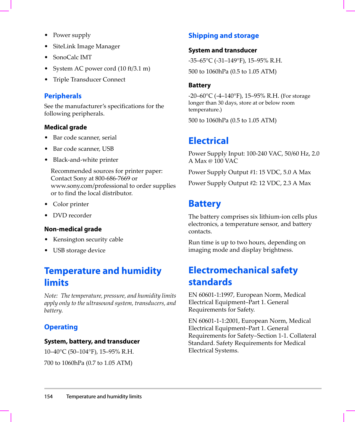
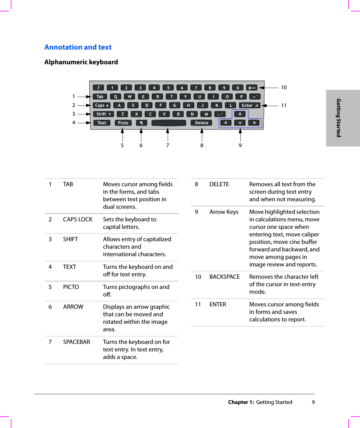
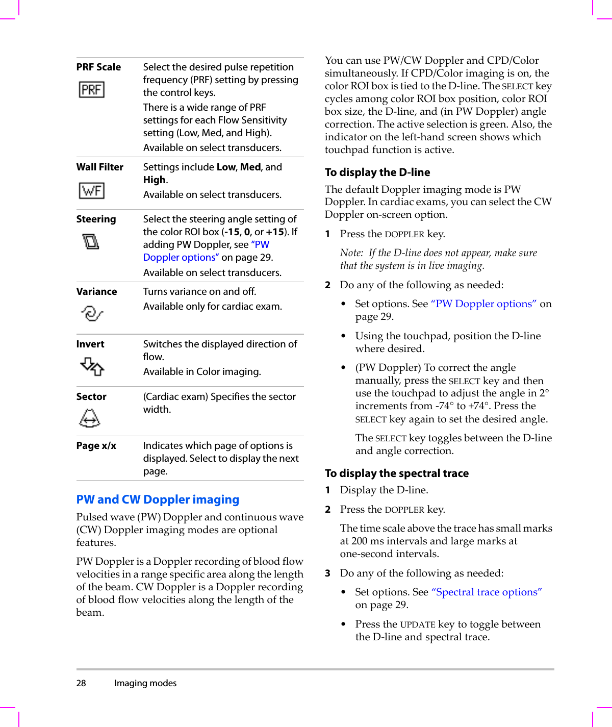
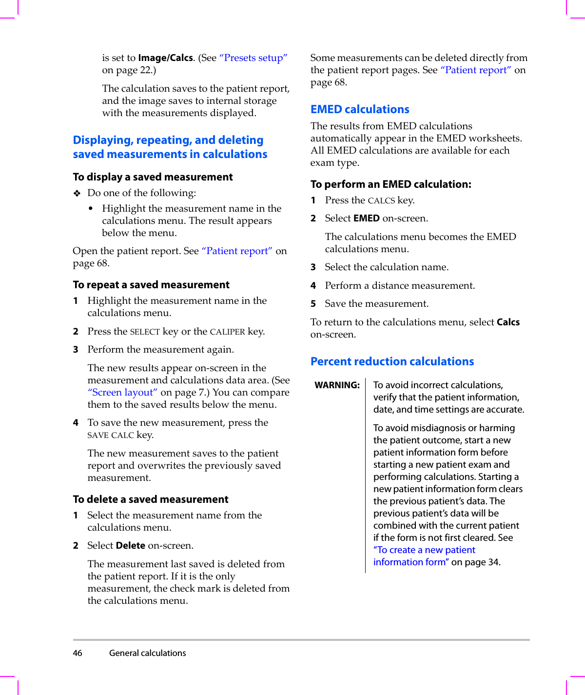
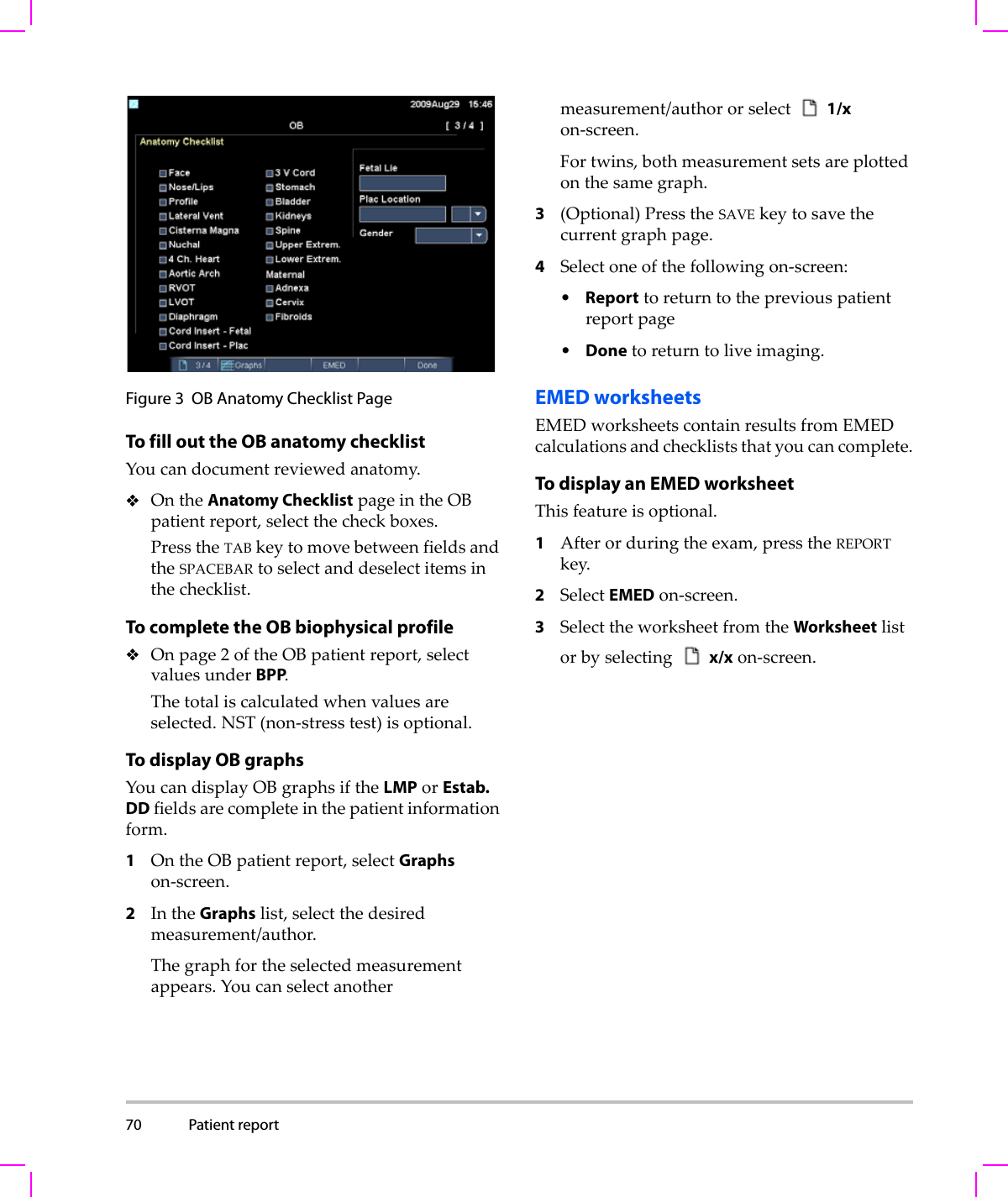
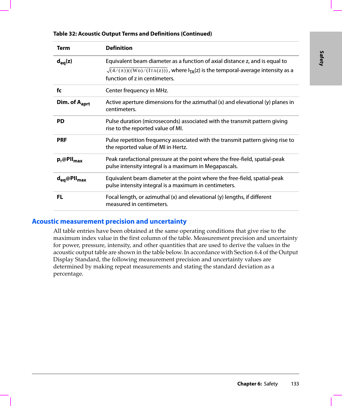
![132 Terms used in the acoustic output tablesTable 32: Acoustic Output Terms and DefinitionsTerm DefinitionISPTA.3 Derated spatial peak, temporal average intensity in units of milliwatts/cm2.TI type Applicable thermal index for the transducer, imaging mode, and exam type.TI value Thermal index value for the transducer, imaging mode, and exam type.MI Mechanical index.Ipa.3@MImax Derated pulse average intensity at the maximum MI in units of W/cm2.TIS (Soft tissue thermal index) is a thermal index related to soft tissues. TIS scan is the soft tissue thermal index in an auto-scanning mode. TIS non-scan is the soft tissue thermal index in the non-autoscanning mode.TIB (Bone thermal index) is a thermal index for applications in which the ultrasound beam passes through soft tissue and a focal region is in the immediate vicinity of bone. TIB non-scan is the bone thermal index in the non-autoscanning mode.TIC (Cranial bone thermal index) is the thermal index for applications in which the ultrasound beam passes through bone near the beam entrance into the body.Aaprt Area of the active aperture measured in cm2.Pr.3 Derated peak rarefactional pressure associated with the transmit pattern giving rise to the value reported under MI (Megapascals).Wo Ultrasonic power, except for TISscan, in which case it is the ultrasonic power passing through a one centimeter window in units of milliwatts.W.3(z1)Derated ultrasonic power at axial distance z1 in units of milliwatts.ISPTA.3(z1)Derated spatial-peak temporal-average intensity at axial distance z1 (milliwatts per square centimeter).z1Axial distance corresponding to the location of maximum [min(W.3(z), ITA.3(z) x 1 cm2)], where z > zbp in centimeters.zbp 1.69 in centimeters.zsp For MI, the axial distance at which pr.3 is measured. For TIB, the axial distance at which TIB is a global maximum (for example, zsp = zb.3) in centimeters.Aaprt()](https://usermanual.wiki/J-Three-Holding/BU2073J.User-Manual-M-Turbo/User-Guide-1089450-Page-142.png)

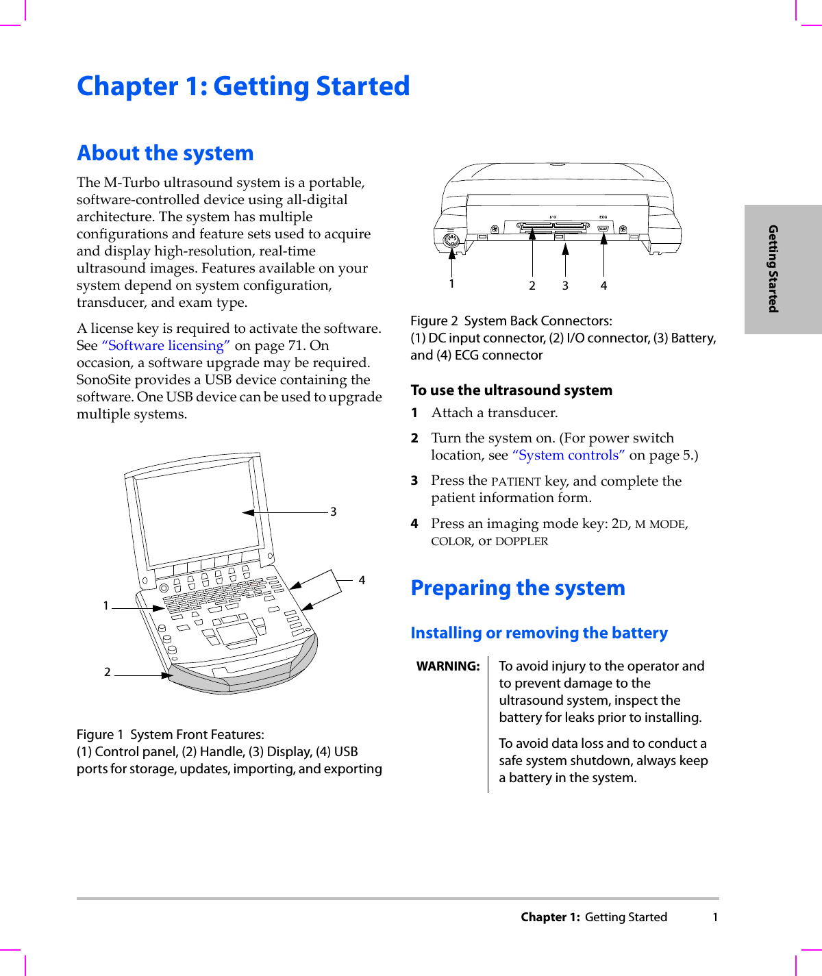
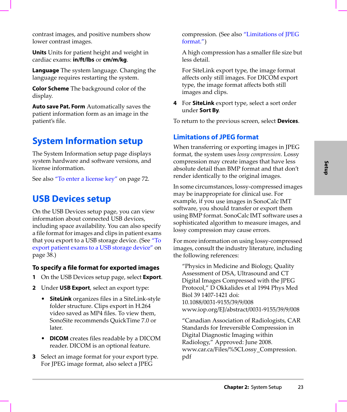
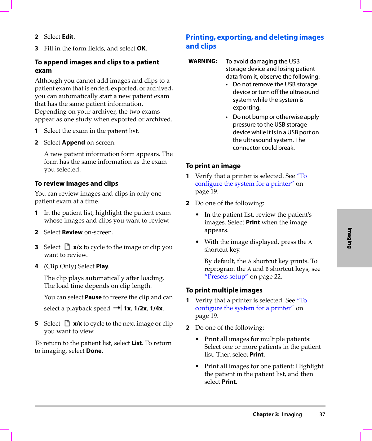
![Chapter 7: References 143ReferencesLVDS=LeftVentricularDimensionatSystoleLVEDV=(7.0*LVDD3)/(2.4+LVDD)where: LVEDV=LeftVentricularEndDiastolicVolumeLVDD=LeftVentricularDimensionatDiastoleLeft Ventricular Mass in gmOh,J.K.,J.B.Seward,A.J.Tajik.TheEchoManual.2ndEdition,Boston:Little,BrownandCompany,(1999),39.LVMass=1.04[(LVID+PWT+IVST)3–LVID3]*0.8+0.6where: LVID=InternalDimensionPWT=PosteriorWallThicknessIVST=InterventricularSeptalThickness1.04=Specificgravityofthemyocardium0.8=CorrectionfactorLeft Ventricular Volume: Biplane Method in mlSchiller,N.B.,P. M . Shah,M.Crawford,et.al.“RecommendationsforQuantitationoftheLeftVentriclebyTwo‐DimensionalEchocardiography.”JournalofAmericanSocietyofEchocardiography.September‐October1989,2:362.where: V=Volumeinmla=Diameterb=Diametern=Numberofsegments(n=20)L=Lengthi=SegmentLeft Ventricular Volume: Single Plane Method in mlSchiller,N.B.,P. M . Shah,M.Crawford,et.al.“RecommendationsforQuantitationoftheLeftVentriclebyTwo‐DimensionalEchocardiography.”JournalofAmericanSocietyofEchocardiography.September‐October1989,2:362.where: V=Volumea=Diametern=Numberofsegments(n=20)L=Lengthi=SegmentLeft Ventricular Dimension (LVD) Fractional Shortening, percentOh,J.K.,J.B.Seward,A.J.Tajik.TheEchoManual.Boston:Little,BrownandCompany,(1994),43‐44.LVDFS=((LVDD–LVDS)/LVDD)*100%where: LVDD=LeftVentricleDimensionatDiastoleLVDS=LeftVentricleDimensionatSystoleLeft Ventricular Posterior Wall Fractional Thickening (LVPWFT), percentLaurenceau,J.L.,M.C.Malergue.TheEssentialsofEchocardiography.LeHague:MartinusNijhoff,(1981),71.LVPWFT=((LVPWS–LVPWD)/LVPWD)*100%where: LVPWS=LeftVentricularPosteriorWallThicknessatSystoleLVPWD=LeftVentricularPosteriorWallThicknessatDiastoleMean Velocity (Vmean) in cm/sVmean=meanvelocityVπ4---⎝⎠⎛⎞ aibiLn---⎝⎠⎛⎞i1=n∑=Vπ4---⎝⎠⎛⎞ ai2Ln---⎝⎠⎛⎞i1=n∑=](https://usermanual.wiki/J-Three-Holding/BU2073J.User-Manual-M-Turbo/User-Guide-1089450-Page-153.png)
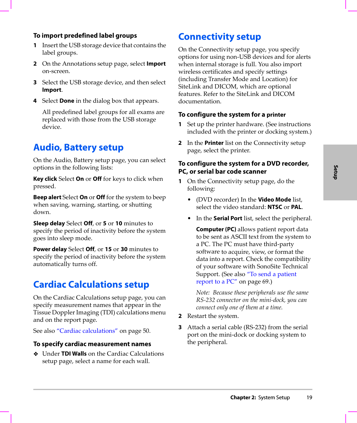
![Chapter 7: References 145ReferencesRight Ventricular Systolic Pressure (RVSP) in mmHgReynolds,Terry.TheEchocardiographer’sPocketReference.SchoolofCardiacUltrasound,ArizonaHeartInstitute,(1993),152.RVSP=4*(VmaxTR)2+RAPwhere: RAP=RightAtrialPressureS/DReynolds,Terry.TheEchocardiographer’sPocketReference.2nded.,SchoolofCardiacUltrasound,ArizonaHeartInstitute,(2000),217.Svelocity/Dvelocitywhere: Svelocity=PulmonaryveinSwaveDvelocity=PulmonaryveinDwaveStroke Index (SI) in cc/m2Mosby’sMedical,Nursing,&AlliedHealthDictionary,4thed.,(1994),1492.SI=SV/BSAwhere: SV=StrokeVolumeBSA=BodySurfaceAreaStroke Volume (SV) Doppler in mlOh,J.K.,J.B.Seward,A.J.Tajik.TheEchoManual.2nded.,Lippincott,Williams,andWilkins,(1999),40,59,62.SV=(CSA*VTI)where CSA=CrossSectionalAreaoftheorifice(LVOTarea)VTI=VelocityTimeIntegraloftheaorticvalveTricuspid Valve Area (TVA)Reynolds,Terry.TheEchocardiographer’sPocketReference.2nded.,SchoolofCardiacUltrasound,ArizonaHeartInstitute,(2000),55,391,452.TVA=220/PHTStroke Volume (SV) 2D and M Mode in mlOh,J.K.,J.B.Seward,A.J.Tajik.TheEchoManual.2nded.,Boston:Little,BrownandCompany,(1994),44.SV=(LVEDV–LVESV)where: SV=StrokeVolumeLVEDV=EndDiastolicVolumeLVEDSV=EndSystolicVolumeVelocity Time Integral (VTI) in cmReynolds,Terry.TheEchocardiographer’sPocketReference.2nded.,SchoolofCardiacUltrasound,ArizonaHeartInstitute,(2000),383.VTI=sumofabs(velocities[n])where:AutoTrace–distance(cm)bloodtravelswitheachejectionperiod.Velocitiesareabsolutevalues.Obstetrical referencesAmniotic Fluid Index (AFI)Jeng,C.J.,etal.“A m n i o t i c FluidIndexMeasurementwiththeFourQuadrantTechniqueDuringPregnancy.”TheJournalofReproductiveMedicine,35:7(July1990),674‐677.Average Ultrasound Age (AUA)ThesystemprovidesanAUAderivedfromthecomponentmeasurementsfromthemeasurementtables.Estimated Date of Delivery (EDD) by Average Ultrasound Age (AUA)Resultsaredisplayedasmonth/day/year.EDD=systemdate+(280days–AUAindays)Estimated Date of Delivery (EDD) by Last Menstrual Period (LMP)ThedateenteredintothepatientinformationforLMPmustprecedethecurrentdate.Resultsaredisplayedasmonth/day/year.](https://usermanual.wiki/J-Three-Holding/BU2073J.User-Manual-M-Turbo/User-Guide-1089450-Page-155.png)