J Three Holding BU2073J Bluetooth Adaptor User Manual M Turbo Ultrasound System User Guide
J-Three International Holding Co., Ltd Bluetooth Adaptor M Turbo Ultrasound System User Guide
Contents
- 1. Users Manual
- 2. User Guide Supplement
- 3. User Manual M Turbo
- 4. User Manual S Series
- 5. Setup Instructions
User Manual M Turbo
M-Turbo
Ultrasound System
User Guide
TM

M-Turbo
Ultrasound System
User Guide
TM

ii
SonoSite,Inc.
2191930thDriveSE
Bothell,WA98021
USA
T:1‐888‐482‐9449or1‐425‐951‐1200
F:1‐425‐951‐1201
SonoSiteLtd
AlexanderHouse
40AWilburyWay
Hitchin
HertsSG40AP
UK
T:+44‐1462‐444800
F:+44‐1462‐444801
M-Turbo, SiteLink, SonoCalc, SonoHD, SonoSite, and the SonoSite logo are registered trademarks or trademarks of SonoSite, Inc.
DICOM is the registered trademark of the National Electrical Manufacturers Association for its standards publications relating to digital
communications of medical information.
Non-SonoSite product names may be trademarks or registered trademarks of their respective owners.
The SonoSite product(s) referenced in this document may be covered by one or more of the following US patents: 5722412, 5817024,
5893363, 6135961, 6203498, 6364839, 6371918, 6383139, 6416475, 6447451, 6471651, 6569101, 6648826, 6575908, 6604630, 6817982,
6835177, 6962566, 7169108, D456509, D461895, D509900, D538432, D544962, D558351, D559390, and by the following counterpart
foreign patents: AU727381, AU730822, CA2373065, CN98106133.8, CN98108973.9, DE60021552.0, DE60029777.2, DE60034670.6,
DE69730563.5, DE6980539.6, DE69831698.3, FR0875203, FR0881492, FR0815793, FR1180970, FR1175713, GB0875203, GB0881492,
GB0815793, GB1180970, GB1180971, GB1175713, IT0881492, IT0815793, IT1175713, KR532359, KR528102, NZ542968,
RCD000897368-0001, SP0881492, SP0815793. Patents pending.
Caution: Federal (United States) law restricts this device to sale by or on the order of a
physician.
P07662‐02 10/2008
Copyright2008bySonoSite,Inc.
Allrightsreserved

iii
Contents
Introduction
Conventions, symbols, and terms ......................................................................... vii
Customer comments .................................................................................................. vii
Chapter 1: Getting Started
About the system .......................................................................................................... 1
Preparing the system ................................................................................................... 1
Installing or removing the battery ................................................................. 1
Using AC power and charging the battery ................................................. 2
Turning the system on or off ............................................................................ 3
Connecting transducers .................................................................................... 3
Inserting and removing USB storage devices ............................................ 4
System controls .............................................................................................................. 5
Screen layout ..................................................................................................................7
General interaction ....................................................................................................... 8
Touchpad and cursor .......................................................................................... 8
On-screen options ............................................................................................... 8
Annotation and text ............................................................................................ 9
Preparing transducers ...............................................................................................10
Training videos .............................................................................................................11
Intended uses ...............................................................................................................11
Chapter 2: System Setup
Displaying the setup pages .....................................................................................15
Restoring default settings ........................................................................................15
A & B Key, Footswitch setup ....................................................................................15
Administration setup .................................................................................................15
Security settings .................................................................................................16
User setup .............................................................................................................16
Exporting or importing user accounts .......................................................17
Exporting and clearing the Event log .........................................................17
Logging in as user ..............................................................................................18
Choosing a secure password .........................................................................18
Annotations setup ......................................................................................................18
Audio, Battery setup ...................................................................................................19
Cardiac Calculations setup ......................................................................................19
Connectivity setup ......................................................................................................19
Date and Time setup ..................................................................................................20
Display Information setup ........................................................................................20
IMT Calculations setup ..............................................................................................20
Network Status setup .................................................................................................20

iv
OB Calculations setup ................................................................................................20
OB Custom Measurements setup .......................................................................... 21
OB Custom Tables setup ...........................................................................................22
Presets setup ................................................................................................................. 22
System Information setup ........................................................................................23
USB Devices setup ...................................................................................................... 23
Limitations of JPEG format ............................................................................. 23
Chapter 3: Imaging
Imaging modes ............................................................................................................ 25
2D imaging ...........................................................................................................25
M Mode imaging ................................................................................................ 26
CPD and color Doppler imaging ...................................................................27
PW and CW Doppler imaging ........................................................................ 28
Adjusting depth and gain ........................................................................................30
Freezing, viewing frames, and zooming ............................................................. 30
Imaging modes and exams available by transducer ...................................... 31
Annotating images ..................................................................................................... 32
Patient information form .......................................................................................... 33
Images and clips .......................................................................................................... 35
Saving images and clips .................................................................................. 35
Reviewing patient exams ...............................................................................36
Printing, exporting, and deleting images and clips ...............................37
ECG Monitoring ............................................................................................................ 38
Chapter 4: Measurements and Calculations
Measurements .............................................................................................................. 41
Working with calipers .......................................................................................41
2D measurements ..............................................................................................42
M Mode measurements ................................................................................... 43
Doppler measurements ................................................................................... 43
General calculations ...................................................................................................45
Calculations menu ............................................................................................. 45
Performing and saving measurements
in calculations ......................................................................................................45
Displaying, repeating, and deleting
saved measurements in calculations .......................................................... 46
EMED calculations ..............................................................................................46
Percent reduction calculations ......................................................................46
Volume calculations ..........................................................................................48
Volume flow calculations ................................................................................ 48
Exam-based calculations ..........................................................................................50
Cardiac calculations .......................................................................................... 50
Gynecology (Gyn) calculations ...................................................................... 58
IMT calculations .................................................................................................. 59
OB calculations ...................................................................................................61

v
Small Parts calculations ....................................................................................64
Transcranial Doppler and Orbital calculations ........................................65
Vascular calculations .........................................................................................67
Patient report ................................................................................................................68
Vascular and cardiac patient reports ...........................................................69
TCD patient report .............................................................................................69
OB patient report ...............................................................................................69
EMED worksheets ...............................................................................................70
Chapter 5: Troubleshooting and Maintenance
Troubleshooting ..........................................................................................................71
Software licensing .......................................................................................................71
Maintenance .................................................................................................................72
Cleaning and disinfecting the ultrasound system .................................73
Cleaning and disinfecting transducers .......................................................74
Cleaning and disinfecting the battery .......................................................75
Cleaning the footswitch ...................................................................................75
Cleaning and disinfecting ECG cables ........................................................76
Recommended disinfectants ..................................................................................77
Chapter 6: Safety
Ergonomic safety .........................................................................................................85
Position the system ...........................................................................................86
Position yourself .................................................................................................86
Take breaks, exercise, and vary activities ...................................................87
Electrical safety classification ..................................................................................87
Electrical safety .............................................................................................................88
Equipment safety ........................................................................................................90
Battery safety ................................................................................................................90
Clinical safety ................................................................................................................92
Hazardous materials ...................................................................................................93
Electromagnetic compatibility ...............................................................................93
Manufacturer’s declaration .............................................................................94
ALARA principle ...........................................................................................................97
Applying ALARA .................................................................................................98
Direct controls .....................................................................................................98
Indirect controls ..................................................................................................99
Receiver controls ................................................................................................99
Acoustic artifacts .........................................................................................................99
Guidelines for reducing MI and TI .........................................................................99
Output display ........................................................................................................... 102
MI and TI output display accuracy ............................................................ 103
Factors that contribute to display uncertainty ..................................... 103
Related guidance documents ..................................................................... 104
Transducer surface temperature rise ................................................................ 104
Acoustic output measurement ............................................................................ 105

vi
In Situ, derated, and water value intensities ...........................................105
Tissue models and equipment survey ......................................................106
Acoustic output tables ............................................................................................107
Terms used in the acoustic output tables ...............................................132
Acoustic measurement precision and uncertainty ..............................133
Labeling symbols ......................................................................................................134
Chapter 7: References
Measurement accuracy ...........................................................................................139
Sources of measurement errors ...........................................................................140
Measurement publications and terminology .................................................141
Cardiac references ............................................................................................141
Obstetrical references .....................................................................................145
Gestational age tables ....................................................................................146
Growth analysis tables ...................................................................................148
Ratio calculations .............................................................................................149
General references ...........................................................................................149
Chapter 8: Specifications
Dimensions ..................................................................................................................153
System ..................................................................................................................153
Display ..................................................................................................................153
Supported transducers ...........................................................................................153
Imaging modes ..........................................................................................................153
Image and clip storage ............................................................................................153
Accessories ..................................................................................................................153
Peripherals ..........................................................................................................154
Temperature and humidity limits ........................................................................154
Operating ............................................................................................................154
Shipping and storage .....................................................................................154
Electrical .......................................................................................................................154
Battery ...........................................................................................................................154
Electromechanical safety standards ...................................................................154
EMC standards classification .................................................................................155
Airborne equipment standards ............................................................................155
DICOM standard ........................................................................................................155
HIPAA standard ..........................................................................................................155
Glossary
Terms .............................................................................................................................157
Abbreviations .............................................................................................................159
Index ...........................................................................................................................169

vii
Introduction
Introduction
ThisM‐TurboUltrasoundSystemUserGuide
providesinformationonpreparingandusingthe
M‐Turbo™ultrasoundsystemandoncleaning
anddisinfectingthesystemandtransducers.It
alsoprovidesreferencesforcalculations,system
specifications,andsafetyandacousticoutput
information.
Theuserguideisforareaderfamiliarwith
ultrasoundtechniques.Itdoesnotprovide
traininginsonographyorclinicalpractices.
Beforeusingthesystem,youmusthave
ultrasoundtraining.
SeetheapplicableSonoSiteaccessoryuserguide
forinformationonusingaccessoriesand
peripherals.Seethemanufacturer’sinstructions
forspecificinformationaboutperipherals.
Conventions, symbols, and
terms
Theuserguidefollowstheseconventions:
•AWARNINGdescribesprecautionsnecessary
topreventinjuryorlossoflife.
•ACautiondescribesprecautionsnecessaryto
protecttheproducts.
•Numberedstepsinproceduresmustbe
performedinorder.
•Itemsinbulletedlistsdonotrequirea
sequence.
•Single‐stepproceduresbeginwith.
Symbolsandtermsusedonthesystemand
transducerareexplainedinChapter 1,Chapter 5,
Chapter 6,andGlossary.
Customer comments
Questionsandcommentsareencouraged.
SonoSiteisinterestedinyourfeedbackregarding
thesystemandtheuserguide.Pleasecall
SonoSiteat888‐482‐9449intheUS.Outsidethe
US,callthenearestSonoSiterepresentative.You
canalsoe‐mailSonoSite
at comments@sonosite.com.
Fortechnicalsupport,pleasecontactSonoSiteas
follows:
SonoSite Technical Support
Phone (US or
Canada):
877-657-8118
Phone (Outside
US and Canada):
425-951-1330
Or call your local
representative.
Fax: 425-951-6700
E-mail: service@sonosite.com
Web site: www.sonosite.com
Click Support & Service.
Europe
Service
Center:
+44-(0)1462-444-800
uk.service@sonosite.com

viii Customer comments
Chapter 1: Getting Started 1
Getting Started
Chapter 1: Getting Started
About the system
TheM‐Turboultrasoundsystemisaportable,
software‐controlleddeviceusingall‐digital
architecture.Thesystemhasmultiple
configurationsandfeaturesetsusedtoacquire
anddisplayhigh‐resolution,real‐time
ultrasoundimages.Featuresavailableonyour
systemdependonsystemconfiguration,
transducer,andexamtype.
Alicensekeyisrequiredtoactivatethesoftware.
See“Softwarelicensing”onpage 71.On
occasion,asoftwareupgrademayberequired.
SonoSiteprovidesaUSBdevicecontainingthe
software.OneUSBdevicecanbeusedtoupgrade
multiplesystems.
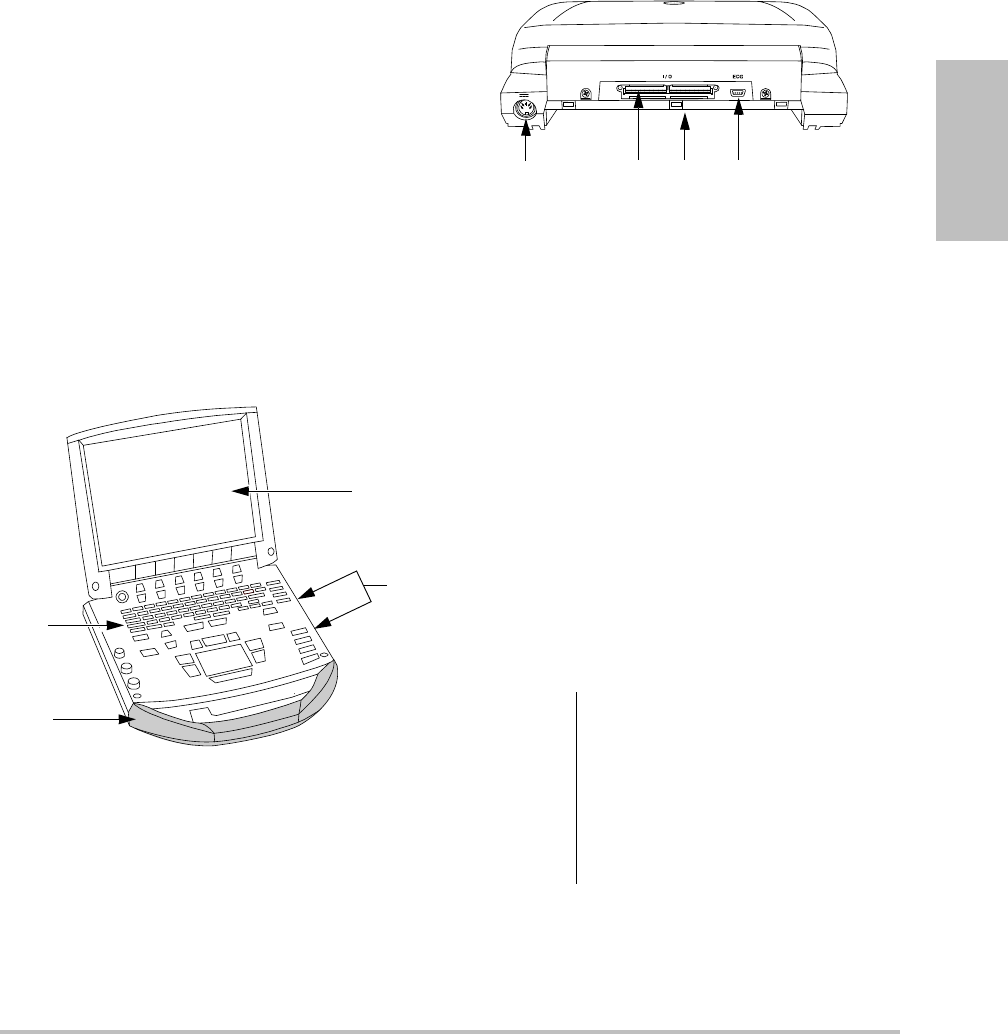
Figure 1 System Front Features:
(1) Control panel, (2) Handle, (3) Display, (4) USB
ports for storage, updates, importing, and exporting
Figure 2 System Back Connectors:
(1) DC input connector, (2) I/O connector, (3) Battery,
and (4) ECG connector
To use the ultrasound system
1Attachatransducer.
2Turnthesystemon.(Forpowerswitch
location,see“Systemcontrols”onpage 5.)
3PressthePATIENTkey,andcompletethe
patientinformationform.
4Pressanimagingmodekey:2D,MMODE,
COLOR,orDOPPLER
Preparing the system
Installing or removing the battery
4
3
2
1
WARNING: To avoid injury to the operator and
to prevent damage to the
ultrasound system, inspect the
battery for leaks prior to installing.
To avoid data loss and to conduct a
safe system shutdown, always keep
a battery in the system.
23 4
1
2 Preparing the system
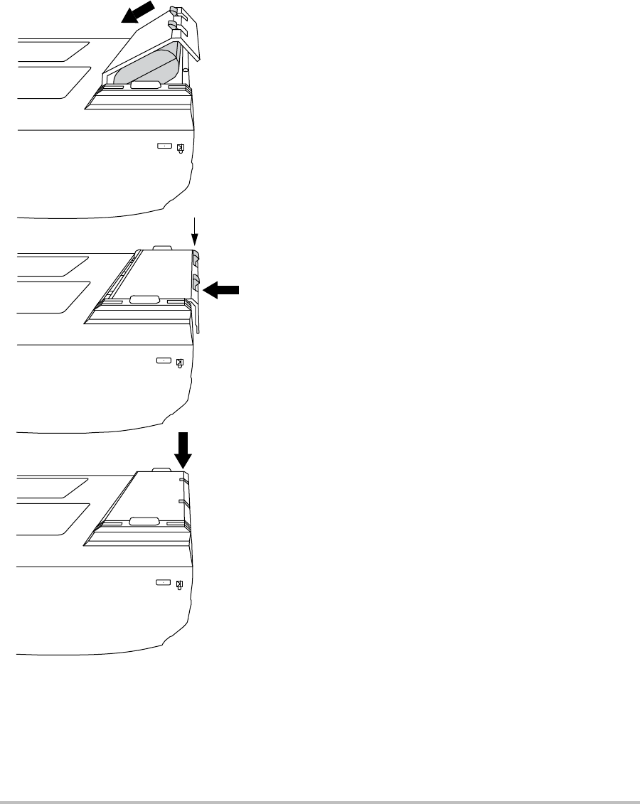
Figure 3 Install the Battery
To install the battery
1Disconnectthepowersupplyfromthe
ultrasoundsystem.
2Removethesystemfromthemini‐dock(if
present)andturnitupsidedown.
3Placethebatteryintothebattery
compartment,ataslightangle.SeeFigure 3.
4Slidethebatteryforwarduntilitlocksinto
place.
5Pushdownonthetwolockingleverstosecure
thebattery.
To remove the battery
1Disconnectthepowersupplyfromthe
ultrasoundsystem.
2Removethesystemfromthemini‐dock(if
present)andturnitupsidedown.
3Pullupthetwolockinglevers.
4Slidethebatteryback.
5Liftthebatteryfromthecompartment.
Using AC power and charging the
battery
Thebatterychargeswhenthesystemis
connectedtotheACpowersupply.Afully
dischargedbatteryrechargesinlessthanfive
hours.
ThesystemcanrunonACpowerandchargethe
batteryifACpowerisconnectedtothesystem
directly,toamini‐dock,ortoadockingsystem.
Thesystemcanrunonbatterypowerforupto
twohours,dependingontheimagingmodeand
thedisplaybrightness.Whenrunningonbattery
power,thesystemmaynotrestartifthebatteryis
low.Tocontinue,connectthesystemtoAC
power.
Locking levers
Chapter 1: Getting Started 3
Getting Started
To operate the system using AC power
1ConnecttheDCpowercablefromthepower
supplytotheconnectoronthesystem.See
Figure 2onpage 1.
2ConnecttheACpowercordtothepower
supplyandtoahospital‐gradeelectrical
outlet.
Turning the system on or off
To turn the system on or off
Pressthepowerswitch.(See“System
controls”onpage 5.)
To wake up the system
Toconservebatterylifewhilethesystemison,
thesystemgoesintosleepmodeifthelidisclosed
orifthesystemisuntouchedforapresettime.To
adjustthetimeforsleepdelay,see“A u d i o ,
Batterysetup”onpage 19.
Pressakey,touchthetouchpad,oropenthe
lid.
Connecting transducers
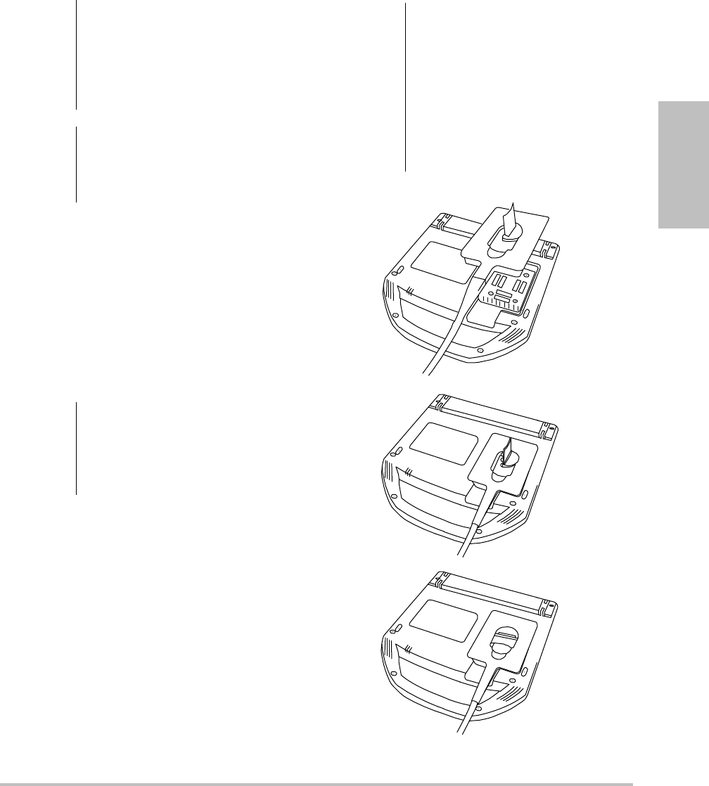
Figure 4 Connect the Transducer
WARNING: The equipment shall be connected
to a center-tapped single phase
supply circuit when users in the
United States connect the
equipment to a 240V supply
system.
Caution: Verify that the hospital supply
voltage corresponds to the power
supply voltage range. See
“Electrical” on page 154.
Caution: Do not use the system if an error
message appears on the display.
Note the error code and turn off the
system. Call SonoSite or your local
representative.
WARNING: To avoid injury to the patient, do
not place the connector on the
patient. Operate the ultrasound
system in a docking system or on a
flat hard surface to allow air flow
past the connector.
Caution: To avoid damaging the transducer
connector, do not allow foreign
material in the connector.

4 Preparing the system
To connect a transducer
1Removethesystemfromthemini‐dock(if
present),andturnitupsidedown.
2Pullthetransducerlatchup,androtateit
clockwise.
3Alignthetransducerconnectorwiththe
connectoronthebottomofthesystem.
4Insertthetransducerconnectorintothe
systemconnector.
5Turnthelatchcounterclockwise.
6Pressthelatchdown,securingthetransducer
connectortothesystem.
To remove a transducer
1Pullthetransducerlatchup,androtateit
clockwise.
2Pullthetransducerconnectorawayfromthe
system.
Inserting and removing USB storage
devices
Imagesandclipsaresavedtointernalstorageand
areorganizedinasortablepatientlist.Youcan
archivetheimagesandclipsfromtheultrasound
systemtoaPCusingaUSBstoragedeviceor
Ethernetconnection.Althoughtheimagesand
clipscannotbeviewedfromaUSBstoragedevice
ontheultrasoundsystem,youcanremovethe
deviceandviewthemonyourPC.
TherearetwoUSBportsonthesystem,andone
onthemini‐dock.ForadditionalUSBports,you
canconnectaUSBhubintoanyUSBport.
Note: Thesystemdoesnotsupportpassword‐
protectedUSBstoragedevices.Makesurethatthe
USBstoragedeviceyouusedoesnothavepassword
protectionenabled.
To insert a USB storage device
InserttheUSBstoragedeviceintoanyUSB
portonthesystemormini‐dock.SeeFigure 1
onpage 1.
TheUSBstoragedeviceisreadywhenthe
USBiconappears.
Toviewinformationaboutthedevice,see
“USBDevicessetup”onpage 23.
To remove a USB storage device
RemovingtheUSBstoragedevicewhilethe
systemisexportingtoitmaycausetheexported
filestobecorruptedorincomplete.
1WaitfivesecondsaftertheUSBanimation
stops.
2RemovetheUSBstoragedevicefromtheport.
WARNING: To avoid damaging the USB storage
device and losing patient data from
it, observe the following:
• Do not remove the USB storage
device or turn off the ultrasound
system while the system is
exporting.
• Do not bump or otherwise apply
pressure to the USB storage
device while it is in a USB port on
the ultrasound system. The
connector could break.
Caution: If the USB icon does not appear in
the system status area on-screen,
the USB storage device may be
defective or password-protected.
Turn the system off and replace the
device.
Chapter 1: Getting Started 5
Getting Started
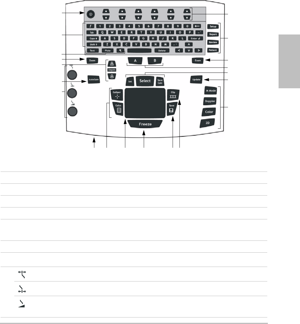
System controls
1 Power switch Turns system on and off.
2 Alphanumeric keys Use to enter text and numbers.
3 Annotation keys See “Alphanumeric keyboard” on page 9.
4 ZOOM Magnifies the image 100%.
5DEPTH UP,
DEPTH DOWN
Decreases and increases imaging depth.
6 AUTO GAIN Adjusts gain automatically.
7Gain
Near Adjusts the gain applied to the near field of the image.
Far Adjusts the gain applied to the far field of the image.
Gain/
Cine Buffer
In live imaging, adjusts the overall gain applied to the entire image. On a
frozen image, moves the cine buffer.
1
2
3
4
6
7
8 9 11 12 13
14
15
17
16
18
19
20
5
10

6 System controls
8 AC power indicator A steady light indicates that AC power is connected. A flashing light
indicates that the system is asleep.
9 CALIPER
CALCS
Displays calipers on-screen for measuring.
Turns the calculations menu on and off.
10 Touchpad Selects, adjusts, and moves items on-screen.
11 FREEZE Stops live imaging and displays a frozen image.
12 SAVE Saves an image to internal storage. If configured, also saves calculations to
the report. See “Presets setup” on page 22.
13 CLIP Saves a clip to internal storage.
14 Control keys Control on-screen options.
15 Forms
SETUP Displays the system settings.
REPORT Accesses the patient report and EMED worksheets.
REVIEW Accesses the patient list, saved images, and archiving functions.
PATIENT Accesses patient information.
16 EXAM Opens exam menu.
17 A & B shortcut keys Keys that you can program to perform common tasks.
18 SET Sets a trace measurement.
SELECT Used with the touchpad to select items on-screen. Also switches between
Color and Doppler options, calipers for measurement, pictograph-marker
position and angle, frozen images in duplex and dual screens, and arrow
position and orientation.
SAVE CALC Saves calculations and their measurements to the patient report.
19 UPDATE Toggles between dual and duplex screens and imaging modes in M Mode
and Doppler (for example, between D-line and Doppler spectral trace).
20 Imaging Modes
M MODE Turns M Mode on, toggles between M-line and M Mode trace.
DOPPLER Turns Doppler on, toggles between D-line and Doppler trace.
COLOR Turns CPD/Color on and off.
2D Turns 2D on.
Chapter 1: Getting Started 7
Getting Started
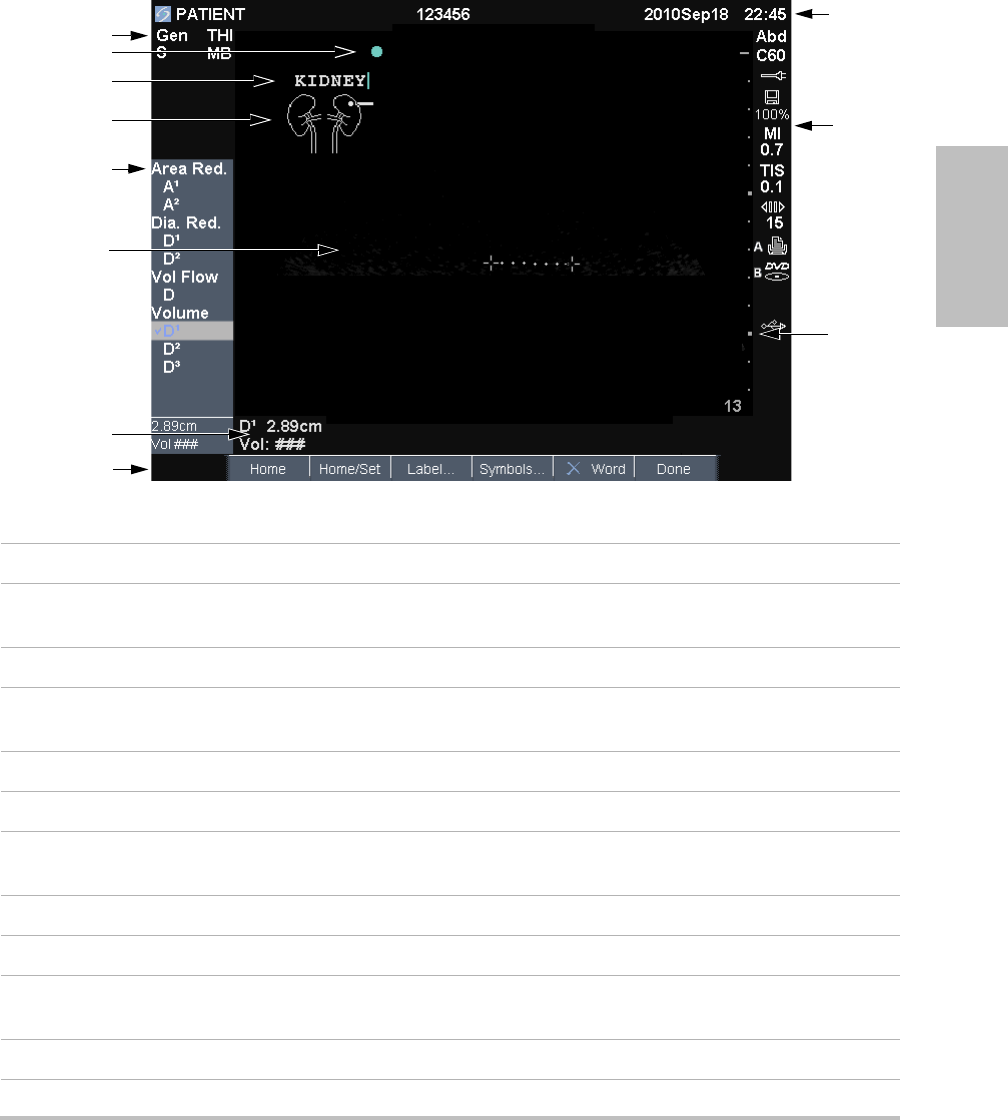
Screen layout
Figure 1 Screen Layout
1 Mode Data Area Current imaging mode information (for example, Gen, Res, THI, and PW).
2 Orientation Marker Provides indication for image orientation. In dual and duplex images, the
orientation marker is green on the active screen.
3 Text Text entered using keyboard.
4 Pictograph Pictograph to indicate anatomy and transducer position. You can select
anatomy and screen location.
5 Calculations Menu Contains available measurements.
6 Image Ultrasound image.
7Measurement and
Calculations Data Area
Current data on measurements and calculations.
8 On-screen Options Options available in the current context.
9 Patient Header Includes current patient name, ID number, institution, user, and date/time.
10 System Status Information on system status (for example, exam type, transducer, AC
connected, battery charging, and USB).
11 Depth Marker Marks in .5 cm, 1 cm, and 5 cm increments depending on depth.
1
5
4
6
11
10
9
7
3
8
2

8 General interaction
General interaction
Touchpad and cursor
Usethetouchpadtoadjustandmoveobjects
on‐screen.Thetouchpadcontrolscaliper
position,CPDorColorboxpositionandsize,the
cursor,andmore.Thearrowkeyscontrolmuch
ofthesamefunctionalityasthetouchpad.
Thecursorappearsinthesetuppages,thepatient
informationform,andpatientreport.Youcontrol
thecursorthroughthetouchpad.Forexample,in
thepatientinformationform,placethecursor
overthelastnamefieldandpresstheSELECT
keytoactivatethatfield.Additionally,youcan
usethecursortoselectcheckboxesanditemsin
lists.
On-screen options
Theon‐screenoptionsletyoumakeadjustments
andselectsettings.Theoptionsavailabledepend
oncontext.
Eachoptioniscontrolledbythepairofkeys
belowit.Dependingontheoption,thecontrol
keysfunctioninoneoffourways:
Cycle Movesthroughalistofsettings
continuously.Theuppercontrolkeycycles
upward.Thelowercontrolkeycyclesdownward.
Up-Down Movesthroughalistofsettings,
stoppingatthetoporbottom.Theuppercontrol
keymovesupward.Thelowercontrolkeymoves
downward.Bydefault,abeepsoundswhenyou
reacheitherendoftherange.(See“A u d i o , Battery
setup”onpage 19.)
On-Off Turnsafeatureonoroff.Youcanpress
eithercontrolkey.Informs,youcaninsteadselect
theoptionbyusingthetouchpadandthe
SELECTkey.
Action Performsanaction.Youcanpresseither
controlkey.Oryoucaninsteadselecttheoption
byusingthetouchpadandtheSELECTkey.
Figure 5 On-screen options (2D imaging shown)
Chapter 1: Getting Started 9
Getting Started
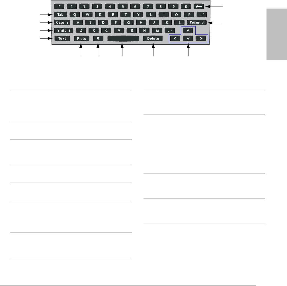
1TAB Moves cursor among fields
in the forms, and tabs
between text position in
dual screens.
2 CAPS LOCK Sets the keyboard to
capital letters.
3 SHIFT Allows entry of capitalized
characters and
international characters.
4 TEXT Turns the keyboard on and
off for text entry.
5 PICTO Turns pictographs on and
off.
6 ARROW Displays an arrow graphic
that can be moved and
rotated within the image
area.
7 SPACEBAR Turns the keyboard on for
text entry. In text entry,
adds a space.
8 DELETE Removes all text from the
screen during text entry
and when not measuring.
9 Arrow Keys Move highlighted selection
in calculations menu, move
cursor one space when
entering text, move caliper
position, move cine buffer
forward and backward, and
move among pages in
image review and reports.
10 BACKSPACE Removes the character left
of the cursor in text-entry
mode.
11 ENTER Moves cursor among fields
in forms and saves
calculations to report.
Annotation and text
Alphanumeric keyboard
2
3
4
11
10
1
56 8 97
10 Preparing transducers
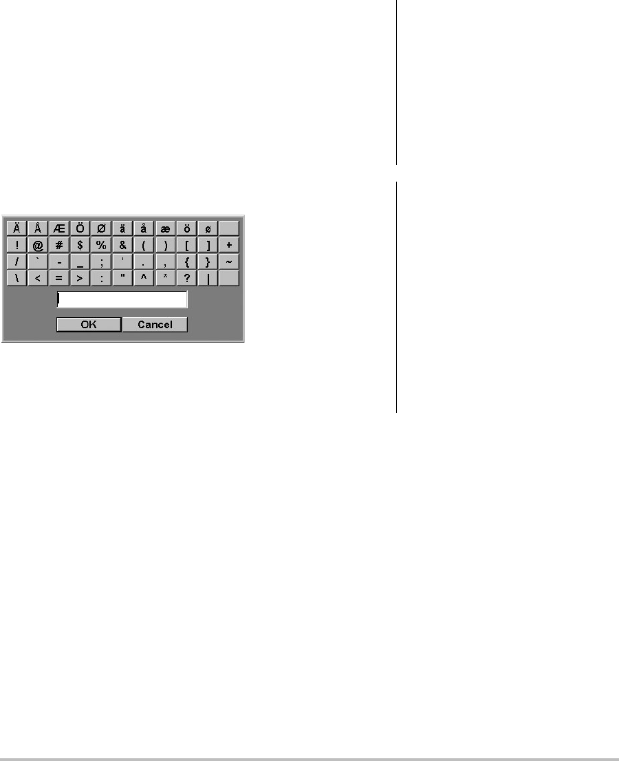
Symbols
Youcanentersymbolsandspecialcharactersin
selectfieldsandforms.Thesymbolsandspecial
charactersavailabledependoncontext.
Patient information form: Last,First,Middle,
PatientID,Accession,Indications,ProcedureID,
User,ReadingDr.,ReferringDr.,andInstitution
fields
DICOM or SiteLink configuration page: Aliasand
AETitlefields
A & B Key, Footswitch setup page: Textfield
Text mode (imaging): Annotationfield
Figure 6 Symbols Dialog Box
To enter symbols or special characters
1Selectthefield,andthenselectSymbols.
2Selectthedesiredsymbolorcharacter.
Youcanalsopressthekeysonthekeyboard.
3SelectOK.
Preparing transducers
Acousticcouplinggelmustbeusedduring
exams.Althoughmostgelsprovidesuitable
acousticcoupling,somegelsareincompatible
withsometransducermaterials.SonoSite
recommendsAquasonic®gelandprovidesa
samplewiththesystem.
Forgeneraluse,applyaliberalamountofgel
betweenthetransducerandthebody.For
invasiveorsurgicaluse,applyatransducer
sheath.
WARNING: Some transducer sheaths contain
natural rubber latex and talc, which
can cause allergic reactions in some
individuals. Refer to 21 CFR 801.437,
User labeling for devices that
contain natural rubber.
Some gels and sterilants can cause
an allergic reaction on some
individuals.
Caution: To avoid damage to the transducer,
use only gels recommended by
SonoSite. Using gels other than the
one recommended by SonoSite can
damage the transducer and void
the warranty. If you have questions
about gel compatibility, contact
SonoSite or your local
representative.
SonoSite recommends that you
clean transducers after each use.
See “Cleaning and disinfecting
transducers” on page 74.

Chapter 1: Getting Started 11
Getting Started
To apply a transducer sheath
SonoSiterecommendstheuseofmarket‐cleared,
transducersheathsforintracavitaryorsurgical
applications.Tolessentheriskofcontamination,
applythesheathonlywhenyouarereadyto
performtheprocedure.
1Placegelinsidethesheath.
2Insertthetransducerintothesheath.
3Pullthesheathoverthetransducerandcable
untilthesheathisfullyextended.
4Securethesheathusingthebandssupplied
withthesheath.
5Checkforandeliminatebubblesbetweenthe
faceofthetransducerandthesheath.
Bubblesbetweenthefaceofthetransducer
andthesheathmayaffecttheultrasound
image.
6Inspectthesheathtoensurethatthereareno
holesortears.
Training videos
TheSonoSite®EducationKey™trainingvideos
areanoptionalfeature.
To display the list of videos
1InserttheEducationKeyUSBdeviceintoa
USBportonthesystem.
2PresstheREVIEWkey.
3Ifthereisanactiveexam,selectListon‐screen.
4SelecttheVideostab.
5Ifthelistdoesnotappear,selectthecorrect
USBdevice:
aSelectSelect USB.
bIntheSelect USB device for media
playback dialog box,selecttheEducation
KeyUSBdevice(“Training”appearsunder
Type),andthenselectSelect.
Note: ImageGalleryisanunsupportedfeature.
To view a video
1Displaythelistofvideos.
2Selectthevideo.
3SelectViewon‐screen.
Thevideobeginsplaying.
4Selectanyofthefollowing,asneeded:
•Adjuststhevolume.Thehigherthe
number,thelouderthesound.Zerois
mute.
•BackRewindsthevideo10seconds.
•Pause Pausesthevideo.
•PlayResumesplayingofapausedvideo.
•ForwardAdvancesthevideo10seconds.
To exit a video
Selectoneofthefollowing:
•Listtoreturntothevideolist.
•Donetoreturnto2Dimaging.
Intended uses
Thissystemtransmitsultrasoundenergyinto
variouspartsofthepatient’sbodytoobtain
ultrasoundimages,asfollows.
Fortheintendedtransducerandimagingmodes
foreachexamtype,see“Imagingmodesand
examsavailablebytransducer”onpage 31.
WARNING: To prevent contamination, the use
of sterile transducer sheaths and
sterile coupling gel is
recommended for clinical
applications of an invasive or
surgical nature. Do not apply the
transducer sheath and gel until you
are ready to perform the procedure.

12 Intended uses
Abdominal Imaging Applications Youcanassess
theliver,kidneys,pancreas,spleen,gallbladder,
bileducts,transplantedorgans,abdominal
vessels,andsurroundinganatomicalstructures
forthepresenceorabsenceofpathology
transabdominally.
Cardiac Imaging Applications Youcanassessthe
heart,cardiacvalves,greatvessels,surrounding
anatomicalstructures,overallcardiac
performance,andheartsizeforthepresenceor
absenceofpathology.
Youcanobtainthepatient’selectrocardiogram
(ECG).TheECGisusedfortimingofcardiac
events.
Gynecology and Infertility Imaging Applications
Youcanassesstheuterus,ovaries,adnexa,and
surroundinganatomicalstructuresforthe
presenceorabsenceofpathology
transabdominallyortransvaginally.
Interventional Imaging Applications Youcanuse
thesystemforultrasoundguidanceinbiopsyand
drainageprocedures,vascularlineplacement,
peripheralnerveblocks,spinalnerveblocksand
taps,ovaharvesting,amniocentesisandother
obstetricalprocedures,andprovideassistance
duringabdominal,breast,andneurological
surgery.
Obstetrical Imaging Applications Youcanassess
thefetalanatomy,viability,estimatedfetal
weight,gestationalage,amnioticfluid,and
surroundinganatomicalstructuresforthe
presenceorabsenceofpathology
transabdominallyortransvaginally.CPDand
Colorimagingareintendedforhigh‐risk
pregnantwomen.High‐riskpregnancy
indicationsinclude,butarenotlimitedto,
multiplepregnancy,fetalhydrops,placental
abnormalities,aswellasmaternalhypertension,
diabetes,andlupus.
Pediatric and Neonatal Imaging Applications
Youcanassessthepediatricandneonatal
abdominal,pelvicandcardiacanatomy,pediatric
hips,neonatalhead,andsurroundinganatomical
structuresforthepresenceorabsenceof
pathology.
Superficial Imaging Applications Youcanassess
thebreast,thyroid,testicle,lymphnodes,
hernias,musculoskeletalstructures,softtissue
structures,ophthalmicstructures,and
surroundinganatomicalstructuresforthe
presenceorabsenceofpathology.Youcanusethe
systemforultrasoundguidanceinbiopsyand
drainageprocedures,vascularlineplacement,
peripheralnerveblocks,andspinalnerveblocks
andtaps.
WARNING: The ECG is not used to diagnose
cardiac arrhythmias and is not
designed for long term cardiac
rhythm monitoring.
WARNING: To prevent injury or misdiagnosis,
do not use this system for
Percutaneous Umbilical Blood
Sampling (PUBS) or in vitro
Fertilization (IVF) The system has
not been validated to be proven
effective for these two uses.
CPD or Color images can be used as
an adjunctive method, not as a
screening tool, for the detection of
structural anomalies of the fetal
heart and as an adjunctive method,
not as a screening tool for the
diagnosis of Intrauterine Growth
Retardation (IUGR).

Chapter 1: Getting Started 13
Getting Started
Transcranial Imaging Applications Youcan
assesstheanatomicalstructuresandvascular
anatomyofthebrainforpresenceorabsenceof
pathology.Youcanuseimagingtemporally,
trans‐occipitally,ortrans‐orbitally.
Vascular Imaging Applications Youcanassessthe
carotidarteries,deepveins,andarteriesinthe
armsandlegs,superficialveinsinthearmsand
legs,greatvesselsintheabdomen,andvarious
smallvesselsfeedingorgansforthepresenceor
absenceofpathology.
WARNING: To avoid injury to the patient, use
only an Orbital (Orb) or
Ophthalmic (Oph) exam type when
performing imaging through the
eye. The FDA has established lower
acoustic energy limits for
ophthalmic use. The system will
not exceed these limits only if the
Orb or Oph exam type is selected.
WARNING: To avoid injury to the patient, use
only an Orbital (Orb) or
Ophthalmic (Oph) exam type when
performing imaging through the
eye. The FDA has established lower
acoustic energy limits for
opthalmic use. The system will not
exceed these limits only if the Orb
or Oph exam type is selected.

14 Intended uses

Chapter 2: System Setup 15
Setup
Chapter 2: System Setup
Thesystemsetuppagesletyoucustomizethe
systemandsetpreferences.
Displaying the setup pages
To display a setup page
1PresstheSETUPkey.
2SelectthesetuppageunderSetup Pages.
Toreturntoimagingfromasetuppage,select
Doneon‐screen.
Restoring default settings
To restore default settings for a setup page
Onthesetuppage,select Reseton‐screen.
To restore all default settings
1Turnthesystemoff.
2ConnectthesystemtoACpower.(See“To
operatethesystemusingACpower”on
page 3.)
3Simultaneouslypress1andthepowerkey.
Thesystembeepsseveraltimes.
A & B Key, Footswitch setup
OntheA&BKey,Footswitchsetuppage,youcan
programtheshortcutkeysandfootswitchto
performcommontasks.Selectfromthefollowing
lists:
A Key, B Key Thefunctionoftheshortcutkeys.By
default,theAshortcutkeyissettoPrintandthe
BshortcutkeyissettoRecord.Theshortcutkeys
arebelowthealphanumerickeypad.
Footswitch (L),Footswitch (R) Thefunctionofthe
leftandrightfootswitches:Save Clip,Record,
Freeze,Save Image,orPrint.Seealso“Toconnect
thefootswitch.”
To connect the footswitch
TheSonoSitefootswitchallowshands‐free
operationwithacustomizabletwo‐pedal
footswitch.Thefootswitchisanoptionalfeature.
1Connectthecables:
•YadaptercabletotheECGconnectoron
themini‐dockordockingsystem
•FootswitchcabletoYadaptercable
2OntheA&BKey,Footswitchsetuppage,
selectafunctionfortheleftandright
footswitches.
Administration setup
OntheAdministrationsetuppage,youcan
configurethesystemtorequireuserstologin
andenterpasswords.Requiredloginhelps
protectpatientdata.Youcanalsoaddanddelete
users,changepasswords,importandexportuser
accounts,andviewtheeventlog.
WARNING: To avoid contamination, do not use
the footswitch in a sterile
environment. The footswitch is not
sterilized.

16 Administration setup
Security settings
Securitysettingsonthesystemallowyoutomeet
theapplicablesecurityrequirementslistedinthe
HIPAAstandard.Usersareultimately
responsibleforensuringthesecurityand
protectionofallelectronicprotectedhealth
informationcollected,stored,reviewed,and
transmittedonthesystem.
To log in as Administrator
1OntheAdministrationsetuppage,type
AdministratorintheNamebox.
2Typetheadministratorpasswordinthe
Passwordbox.
Ifyoudon’thavetheadministratorpassword,
contactSonoSite.(See“SonoSiteTechnical
Support”onpage vii.)
3SelectLogin.
To log out as Administrator
Turnofforrestartthesystem.
To require user login
YoucansetthesystemtodisplaytheUserLogin
screenatstartup.
1LoginasAdministrator.
2IntheUser Loginlist,selectOn.
•Onrequiresausernameandpasswordat
startup.
•Offallowsaccesstothesystemwithouta
usernameandpassword.
To change the administrator password or let
users change passwords
1LoginasAdministrator.
2UnderUser List,selectAdministrator.
3Doanyofthefollowing:
• Changetheadministratorpassword:
UnderUser Information,typethenew
passwordinthePasswordboxand
Confirmbox.(See“Choosingasecure
password”onpage 18.)
•Letuserschangetheirpasswords:Select
thePassword changescheckbox.
4SelectSave.
User setup
To add a new user
1LoginasAdministrator.
2SelectNew.
3UnderUser Information,fillintheName,
Password,andConfirmboxes.(See“Choosing
asecurepassword”onpage 18.)
4(Optional)IntheUser box,typetheuser’s
initialstodisplaytheminthepatientheader
andtheUserfieldinthepatientinformation
form.
5(Optional)SelecttheAdministration Access
checkboxtoallowaccesstoalladministration
privileges.
6SelectSave.
To modify user information
1LoginasAdministrator.
WARNING: Health care providers who maintain
or transmit health information are
required by the Health Insurance
Portability and Accountability Act
(HIPAA) of 1996 and the European
Union Data Protection Directive
(95/46/EC) to implement
appropriate procedures: to ensure
the integrity and confidentiality of
information; to protect against any
reasonably anticipated threats or
hazards to the security or integrity
of the information or unauthorized
uses or disclosures of the
information.

Chapter 2: System Setup 17
Setup
2UnderUser List,selecttheuser.
3UnderUser Information,makechangesas
desired.
4SelectSave.
Anychangetotheusernamereplacesthe
previousname.
To delete a user
1LoginasAdministrator.
2UnderUser List,selecttheuser.
3SelectDelete.
4SelectYes .
To change a user password
1LoginasAdministrator.
2IntheUser List,selecttheuser.
3TypethenewpasswordinthePasswordbox
andConfirmbox.
4SelectSave.
Exporting or importing user accounts
Theexportandimportcommandsletyou
configuremultiplesystemsandbackupuser
accountinformation.
To export user accounts
1InsertaUSBstoragedevice.
2LoginasAdministrator.
3SelectExporton‐screen.AlistofUSBdevices
appears.
4SelecttheUSBstoragedevice,andselect
Export.
Allusernamesandpasswordsarecopiedto
theUSBstoragedevice.
To import user accounts
1InserttheUSBstoragedevicethatcontainsthe
accounts.
2LoginasAdministrator.
3SelectImporton‐screen.
4SelecttheUSBstoragedevice,andselect
Import.
5Restartthesystem.
Allusernamesandpasswordsonthesystem
arereplacedwiththeimporteddata.
Exporting and clearing the Event log
TheEventlogcollectserrorsandeventsandcan
beexportedtoaUSBstoragedeviceandreadon
aPC.
To display the Event log
1LoginasAdministrator.
2SelectLogon‐screen.
TheEventlogappears.
Toreturntothepreviousscreen,selectBack.
To export the Event log
TheEventlogandtheDICOMnetworkloghave
thesamefilename(log.txt).Exportingeitherone
toaUSBstoragedeviceoverwritesanyexisting
log.txtfile.
1InsertaUSBstoragedevice.
2SelectLogandthenselectExport on‐screen.
AlistofUSBdevicesappears.
3SelecttheUSBstoragedevice,andselect
Export.
TheEventlogisatextfilethatyoucanopenina
text‐editingapplication(forexample,Microsoft
WordorNotepad).
To clear the Event log
1DisplaytheEventlog.
2SelectClearon‐screen.
3SelectYes .

18 Annotations setup
Logging in as user
Ifuserloginisrequired,theUserLoginscreen
appearswhenyouturnonthesystem.(See“To
requireuserlogin”onpage 16.)
To log in as user
1Turnonthesystem.
2IntheUser Loginscreen,typeyournameand
password,andselectOK.
To log in as guest
Guestscanscanbutcan’taccesssystemsetupand
patientinformation.
1Turnonthesystem.
2IntheUser Loginscreen,selectGuest.
To change your password
1Turnonthesystem.
2IntheUser Loginscreen,selectPassword.
3Typeyouroldandnewpasswords,confirm
thenewpassword,andthenselectOK.
Choosing a secure password
Toensuresecurity,chooseapasswordthat
containsuppercasecharacters(A‐Z),lowercase
characters(a‐z),andnumbers(0‐9).Passwords
arecase‐sensitive.
Annotations setup
OntheAnnotationssetuppage,youcan
customizepredefinedlabelsandsetthe
preferenceformanagingtextwhenunfreezing
images.
Forinstructionstoannotateimages,see
“Annotatingimages”onpage 32.
To predefine a label group
Youcanspecifywhichlabelsareavailableforan
examtypewhenannotatinganimage.(See“To
placetextonanimage”onpage 32.)
1IntheExamlistontheAnnotationssetup
page,selecttheexamtypewhoselabelsyou
wanttospecify.
2ForGroup,select A, B, or Cforthelabelgroup
youwantassociatedwiththatexam.
Thepresetlabelsappearfortheselectedgroup.
3Doanyofthefollowing:
•Addacustomlabeltothegroup:Typethe
labelintheTextbox,andselectAdd.
• Renamealabel:Selectthelabel,typethe
newnameintheTextbox,andselect
Rename.
•Movealabelwithinthegroup:Selectthe
label,andthenselecttheon‐screenupor
downarrow.
• Deletealabelfromagroup:Selectthe
label,andselectDelete.
Youcanusesymbolsinlabels.See“Symbols”
onpage 10.
To specify text retention when unfreezing
Youcanspecifywhichtexttokeepwhenyou
unfreezeanimageorchangetheimaginglayout.
IntheUnfreezelistontheAnnotationssetup
page,selectKeep All Text,Keep Home Text,or
Clear All Text.
ThedefaultsettingisKeep All Text.For
informationonsettingthehomeposition,see
“Toresetthehomeposition”onpage 33.
To export predefined label groups
1InsertaUSBstoragedevice.
2OntheAnnotationssetuppage,selectExport.
AlistofUSBdevicesappears.
3SelecttheUSBstoragedevice,andselect
Export.
Acopyofallpredefinedlabelgroupsforall
examssavestotheUSBstoragedevice.

Chapter 2: System Setup 19
Setup
To import predefined label groups
1InserttheUSBstoragedevicethatcontainsthe
labelgroups.
2OntheAnnotationssetuppage,selectImport
on‐screen.
3SelecttheUSBstoragedevice,andthenselect
Import.
4SelectDoneinthedialogboxthatappears.
Allpredefinedlabelgroupsforallexamsare
replacedwiththosefromtheUSBstorage
device.
Audio, Battery setup
OntheAudio,Batterysetuppage,youcanselect
optionsinthefollowinglists:
Key clickSelectOnorOffforkeystoclickwhen
pressed.
Beep alert SelectOnorOffforthesystemtobeep
whensaving,warning,starting,orshutting
down.
Sleep delaySelectOff,or5or10minutesto
specifytheperiodofinactivitybeforethesystem
goesintosleepmode.
Power delaySelectOff,or15or30minutesto
specifytheperiodofinactivitybeforethesystem
automaticallyturnsoff.
Cardiac Calculations setup
OntheCardiacCalculationssetuppage,youcan
specifymeasurementnamesthatappearinthe
TissueDopplerImaging(TDI)calculationsmenu
andonthereportpage.
Seealso“Cardiaccalculations”onpage 50.
To specify cardiac measurement names
UnderTDI WallsontheCardiacCalculations
setuppage,selectanameforeachwall.
Connectivity setup
OntheConnectivitysetuppage,youspecify
optionsforusingnon‐USBdevicesandforalerts
wheninternalstorageisfull.Youalsoimport
wirelesscertificatesandspecifysettings
(includingTransferModeandLocation)for
SiteLinkandDICOM,whichareoptional
features.RefertotheSiteLinkandDICOM
documentation.
To configure the system for a printer
1Setuptheprinterhardware.(Seeinstructions
includedwiththeprinterordockingsystem.)
2InthePrinterlistontheConnectivitysetup
page,selecttheprinter.
To configure the system for a DVD recorder,
PC, or serial bar code scanner
1OntheConnectivitysetuppage,dothe
following:
•(DVDrecorder)IntheVideo Modelist,
selectthevideostandard:NTSCorPAL.
•IntheSerial Portlist,selecttheperipheral.
Computer (PC) allowspatientreportdata
tobesentasASCIItextfromthesystemto
aPC.ThePCmusthavethird‐party
softwaretoacquire,view,orformatthe
dataintoareport.Checkthecompatibility
ofyoursoftwarewithSonoSiteTechnical
Support.(Seealso“Tosendapatient
reporttoaPC”onpage 69.)
Note: Becausetheseperipheralsusethesame
RS‐232connectoronthemini‐dock,youcan
connectonlyoneofthematatime.
2Restartthesystem.
3Attachaserialcable(RS‐232)fromtheserial
portonthemini‐dockordockingsystemto
theperipheral.

20 Date and Time setup
To receive storage alerts
OntheConnectivitysetuppage,select
Internal Storage Capacity Alert.
Thesystemdisplaysamessageifinternal
storageisnearcapacitywhenyouendan
exam.Thesystemthendeletesarchived
patientexamsifspecifiedinDICOM.
Date and Time setup
To set the date and time
OntheDateandTimesetuppage,dothe
following:
•IntheDate box,typethecurrentdate.
•IntheTime box,typethecurrenttimein
24 hourformat(hoursandminutes).
Display Information setup
OntheDisplayInformationsetuppage,youcan
specifywhichdetailsappearon‐screenduring
imaging.Youcanselectsettingsinthefollowing
sections:
Patient HeaderInformationthatappearsinthe
patientheader.
Mode DataImaginginformation.
System StatusSystemstatusinformation.
IMT Calculations setup
OntheIMTCalculationssetuppage,youcan
customizetheIMTcalculationsmenu.Youcan
specifyuptoeightmeasurementnamesforboth
rightsideandleftsidecalculations.The
measurementnamesalsoappearinthepatient
report.
Seealso“IMTcalculations”onpage 59.
To customize the IMT calculations menu
OntheIMTCalculationssetuppage,dothe
following:
•UnderIMT Calculations,select
measurementnamesfromthelists,or
selectNone.
Theselectednamesappearinthe
calculationsmenuandinthepatient
report.
•Typethedesiredwidthinthe
Region width (mm)box.
Network Status setup
TheNetworkStatussetuppagedisplays
informationonsystemIPaddress,Location,
EthernetMACaddress,andthewireless
connectionifany.
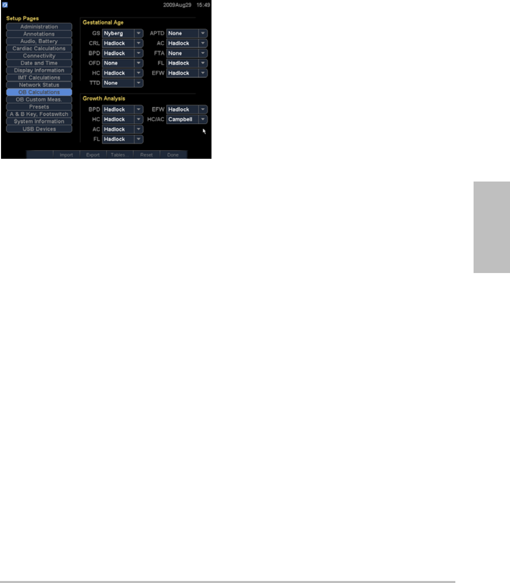
OB Calculations setup
OntheOBCalculationssetuppage,youselect
authorsforOBcalculationtables.Youcanalso
importorexportadditionalOBcalculationtables.
Seealso“OBcalculations”onpage 61.
WARNING: To obtain accurate obstetrics
calculations, an accurate date and
time are critical. Verify that the date
and time are accurate before each
use of the system. The system does
not automatically adjust for
daylight saving time changes.
Chapter 2: System Setup 21
Setup
Figure 1 OB Calculations Setup Page
To specify gestational age and growth
analysis
1OntheOBCalculationssetuppage,selectthe
desiredOBauthors(orselectNone)inthe
measurementlistsunderGestational Ageand
Growth Analysis.
Selectinganauthorplacestheassociated
measurementonthecalculationsmenu.
2(Optional)SelectMoretodisplaythelistof
user‐definedcustommeasurementsandto
associateacustomtableforthecustom
measurement.
Thisoptionisavailableonlywhena
user‐definedcustomtablehasbeencreated
forthecustommeasurement.
To export OB calculation tables
1InsertaUSBstoragedevice.
2OntheOBCalculationssetuppage,select
Export.AlistofUSBdevicesappears.
3SelecttheUSBstoragedevice,andselect
Export.
Alluser‐definedtablesandmeasurementsare
copiedtotheUSBstoragedevice.
To import OB calculationtables
Tablesthatyouimportareaddedtothosealready
onthesystem.
1InserttheUSBstoragedevicethatcontainsthe
tables.
2OntheOBCalculationssetuppage,select
Importon‐screen.
3SelecttheUSBstoragedevice,andthenselect
Import.
4SelectOKinthedialogboxthatappears.
Thesystemrestarts.
OB Custom Measurements
setup
OntheOBCustomMeasurementssetuppage,
youcandefinemeasurementsthatappearinthe
OBcalculationsmenuandOBreport.OBCustom
Measurementsisanoptionalfeature.
Seealso“OBcalculations”onpage 61.
To set up OB custom measurements
Youcansaveuptofivecustommeasurements
thatappearintheOBcalculationsmenuandOB
report.
1OntheOBCustomMeasurementssetuppage,
selectNew.
2IntheNamebox,typeauniquename.
3IntheTypelist,selectthedesired
measurementtype.
4SelectSave.
To delete an OB custom measurement
IfyoudeleteanOBcustommeasurementduring
anexam,theexamends.
1OntheOBCustomMeasurementssetuppage,
highlightthemeasurementintheCustom
Measurementslist.
2SelectDelete Last.

22 OB Custom Tables setup
3SelectYes .
Theexamends,andanytablesandreport
dataassociatedwiththemeasurementare
removedfromthesystem.
OB Custom Tables setup
OntheOBCustomTablessetuppages,youcan
customizegrowthtablesthatappearinthe
calculationsmenuandpatientreport.
Gestational Age Table Measurements Thesystem
providesgestationalagemeasurementsby
selectedauthorsforCRL,GS,BPD,OFD,HC,AC,
FL,APTD,TTD,FTA,and5 additionalcustom
measurementlabels.
Growth Analysis Table MeasurementsThe
systemprovidesgrowthgraphsorcurvesfor
BPD,HC,AC,FL,EFW,andHC/AC.
To view OB tables
1OntheOBCalculationsorOBCustom
Measurementssetuppage,selectTables
on‐screen.
2Selectthedesiredtableand
measurement/author.
To create a new OB custom table
YoucancreatetwocustomtablesforeachOB
measurement.
1OntheOBCalculationsorOBCustom
Measurementssetuppage,selectTables
on‐screen.
2Selectthedesiredtable(GestationalAgeor
Growth Analysis).
3IntheMeasurementlist,selectthe
measurementforthecustomtable.
4SelectNewon‐screen.
5IntheAuthorbox,typeauniquename.
6Enterthedata.
7SelectSaveon‐screen.
Todisplaythemeasurementforthecustomtable
inthecalculationsmenu,see“Tospecify
gestationalageandgrowthanalysis”onpage 21.
To edit or delete an OB custom table
1OntheOBCalculationsorOBCustom
Measurementssetuppage,selectTables
on‐screen.
2SelecttheOBcustomtable.
3Selectoneofthefollowingon‐screen:
•EditEnterdata,andthenselectSave
on‐screen.
•Deletetoremovethecustomtable.Select
Yes.
Presets setup
ThePresetssetuppagehassettingsforgeneral
preferences.Youcanselectfromthefollowing
lists:
Doppler ScaleSelectcm/sorkHz.
Duplex ThelayoutfordisplayingMModetrace
andDopplerspectraltrace:1/3 2D, 2/3 Trace;1/2
2D, 1/2 Trace;orFull 2D, Full Trace.
Live TraceSelectPeakorMean.
Thermal Index YoucanselectTIS,TIB,orTIC.The
defaultsettingisbasedonexamtype:OBisTIB,
TCDisTIC,andallothersareTIS.
Save KeyBehavioroftheSAVEkey.Image Only
savestheimagetointernalstorage.Image/Calcs
savestheimagetointernalstorageandsavesthe
currentcalculationtothepatientreport.
Dynamic RangeSettingsinclude-3,-2,-1,0,+1,
+2,or+3.Negativenumbersshowhigher
WARNING: Prior to use, verify that custom table
data entries are correct. The system
does not confirm the accuracy of
the custom table data entered by
the user.

Chapter 2: System Setup 23
Setup
contrastimages,andpositivenumbersshow
lowercontrastimages.
UnitsUnitsforpatientheightandweightin
cardiacexams:in/ft/lbsorcm/m/kg.
LanguageThesystemlanguage.Changingthe
languagerequiresrestartingthesystem.
Color SchemeThebackgroundcolorofthe
display.
Auto save Pat. FormAutomaticallysavesthe
patientinformationformasanimageinthe
patient’sfile.
System Information setup
TheSystemInformationsetuppagedisplays
systemhardwareandsoftwareversions,and
licenseinformation.
Seealso“Toenteralicensekey”onpage 72.
USB Devices setup
OntheUSBDevicessetuppage,youcanview
informationaboutconnectedUSBdevices,
includingspaceavailability.Youcanalsospecify
afileformatforimagesandclipsinpatientexams
thatyouexporttoaUSBstoragedevice.(See“To
exportpatientexamstoaUSBstoragedevice”on
page 38.)
To specify a file format for exported images
1OntheUSBDevicessetuppage,selectExport.
2UnderUSB Export,selectanexporttype:
•SiteLinkorganizesfilesinaSiteLink‐style
folderstructure.ClipsexportinH.264
videosavedasMP4files.Toviewthem,
SonoSiterecommendsQuickTime7.0or
later.
•DICOMcreatesfilesreadablebyaDICOM
reader.DICOMisanoptionalfeature.
3Selectanimageformatforyourexporttype.
ForJPEGimageformat,alsoselectaJPEG
compression.(Seealso“LimitationsofJPEG
format.”)
Ahighcompressionhasasmallerfilesizebut
lessdetail.
ForSiteLinkexporttype,theimageformat
affectsonlystillimages.ForDICOMexport
type,theimageformataffectsbothstill
imagesandclips.
4ForSiteLinkexporttype,selectasortorder
underSort By.
Toreturntothepreviousscreen,selectDevices.
Limitations of JPEG format
WhentransferringorexportingimagesinJPEG
format,thesystemuseslossycompression.Lossy
compressionmaycreateimagesthathaveless
absolutedetailthanBMPformatandthatdon’t
renderidenticallytotheoriginalimages.
Insomecircumstances,lossy‐compressedimages
maybeinappropriateforclinicaluse.For
example,ifyouuseimagesinSonoCalcIMT
software,youshouldtransferorexportthem
usingBMPformat.SonoCalcIMTsoftwareusesa
sophisticatedalgorithmtomeasureimages,and
lossycompressionmaycauseerrors.
Formoreinformationonusinglossy‐compressed
images,consulttheindustryliterature,including
thefollowingreferences:
“PhysicsinMedicineandBiology,Quality
AssessmentofDSA,UltrasoundandCT
DigitalImagesCompressedwiththeJPEG
Protocol,”DOkkalidesetal1994PhysMed
Biol391407‐1421doi:
10.1088/0031‐9155/39/9/008
www.iop.org/EJ/abstract/0031‐9155/39/9/008
“CanadianAssociationofRadiologists,CAR
StandardsforIrreversibleCompressionin
DigitalDiagnosticImagingwithin
Radiology,”Approved:June2008.
www.car.ca/Files/%5CLossy_Compression.
pdf

24 USB Devices setup
Chapter 3: Imaging 25
Imaging
Chapter 3: Imaging
Imaging modes
Thesystemhasahigh‐performancedisplayand
advancedimage‐optimizationtechnologythat
significantlysimplifiesusercontrols.Imaging
modesavailabledependonthetransducerand
examtype.See“Imagingmodesandexams
availablebytransducer”onpage 31.
2D imaging
2Disthesystemʹsdefaultimagingmode.The
systemdisplaysechoesintwodimensionsby
assigningabrightnesslevelbasedontheecho
signalamplitude.Toachievethebestpossible
imagequality,properlyadjustthedisplay
brightness,gain,depthsettings,viewingangle,
andexamtype.Also,selectanoptimization
settingthatbestmatchesyourneeds.
To display the 2D image
1Doanyofthefollowing:
•Turnonthesystem.
•Pressthe2Dkey.
2Setoptionsasdesired.See“2Doptions.”
2D options
In2Dimaging,youcanselectthefollowing
on‐screenoptions.
Optimize Settings are as follows:
•Res provides the best possible
resolution.
•Gen provides a balance between
resolution and penetration.
•Pen provides the best possible
penetration.
Some of the parameters optimized
to provide the best image include
focal zones, aperture size, frequency
(center and bandwidth), and
waveform. They cannot be adjusted
by the user.
Dynamic
Range
Adjusts the grayscale range: -3, -2,
-1, 0, +1, +2, +3.
The positive range increases the
number of grays displayed, and the
negative range decreases the
number of grays displayed.
Dual Displays side-by-side 2D images.
Select Dual, and then press the
UPDATE key to display the second
screen and to toggle between the
screens. With both images frozen,
press the UPDATE key to toggle
between the images.
To return to full-screen 2D imaging,
select Dual or press the 2D key.
26 Imaging modes
M Mode imaging
Motionmode(M Mode)isanextensionof2D.It
providesatraceofthe2Dimagedisplayedover
time.Asinglebeamofultrasoundistransmitted,
andreflectedsignalsaredisplayedasdotsof
varyingintensities,whichcreatelinesacrossthe
screen.
To display the M-line
1PresstheMMODEkey.
Note: IftheM‐linedoesnotappear,makesurethat
theimageisn’tfrozen.
2UsethetouchpadtopositiontheM‐linewhere
desired.
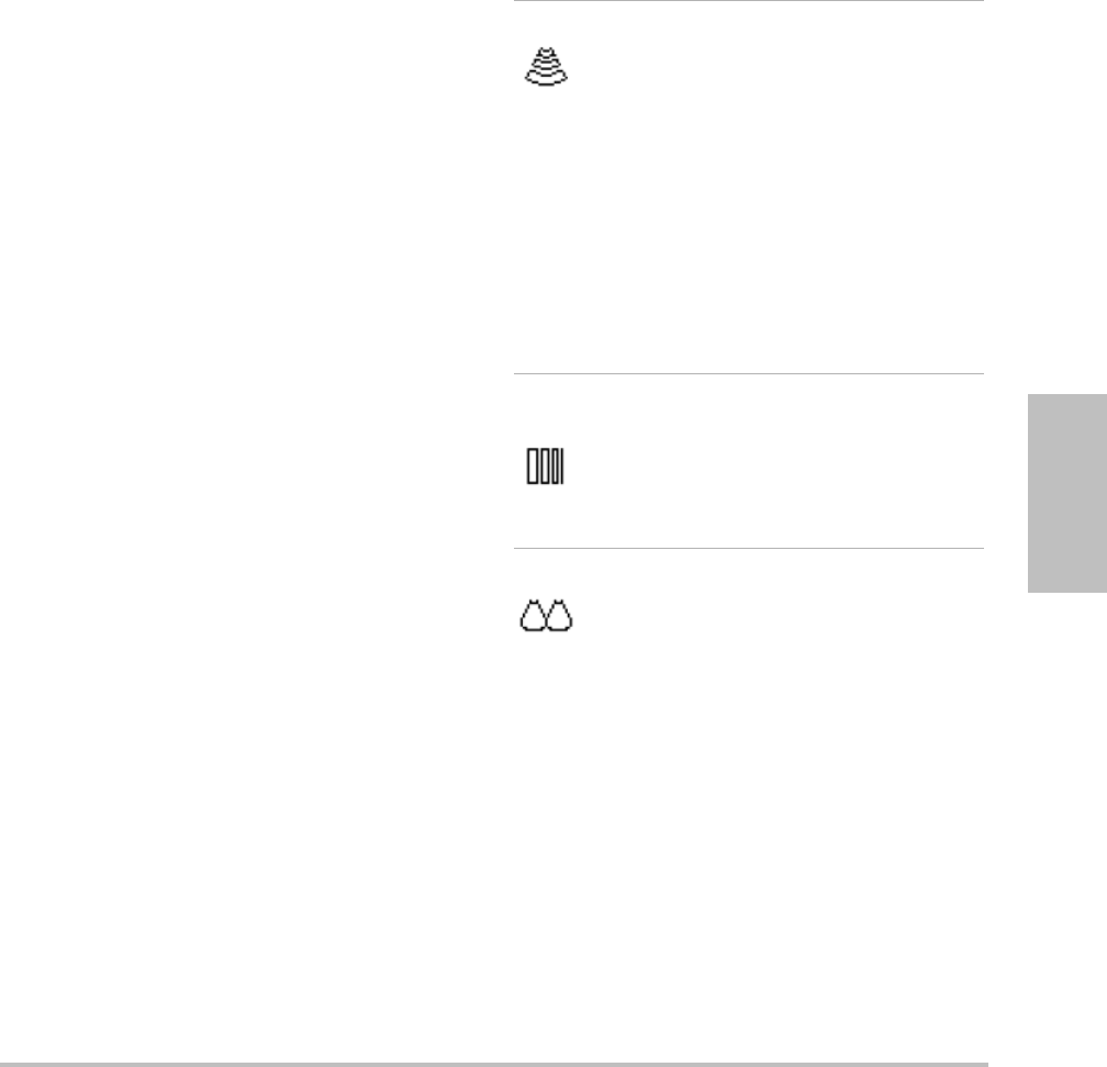
LVO On,
LVO Off
LVO On turns on Left Ventricular
Opacification. LVO Off turns off this
option.
Use LVO for cardiac exams in 2D
imaging mode when using an
imaging contrast agent. LVO lowers
the mechanical index (MI) of the
system to enhance visualization of
the contrast agent and endocardial
border.
This option depends on transducer
and exam type.
Orientation Select from four image orientations:
U/R (Up/Right), U/L (Up/Left), D/L
(Down/Left), D/R (Down/Right).
Brightness Adjusts the display brightness.
Settings range from 1 to 10.
The display brightness affects
battery life. To conserve battery life,
adjust brightness to a lower setting.
Biopsy Turns biopsy guidelines on and off.
This feature depends on transducer
type. See the SonoSite Biopsy user
guide.
Biopsy is not available when the
ECG cable is connected.
Guide Turns the guideline on and off.
This feature depends on transducer
and exam type. See the user guide
for L25x transducer and needle
guide.
Sector (Cardiac exam) Specifies the sector
width.
SonoMB On is available only for
Sector Full.
SonoMB
(MB)
MB On and MB Off turn SonoMB™
multi-beam imaging technology on
and off. When SonoMB is on, MB
appears in the upper left-hand
screen.
SonoMB depends on transducer and
exam type.
ECG Displays the ECG trace. See “ECG
Monitoring” on page 38.
This feature is optional and requires
a SonoSite ECG cable.
Clips Displays the clips options. See “To
capture and save a clip” on page 35.
This feature is optional.
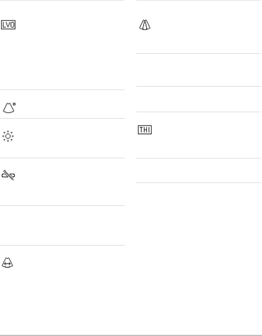
THI Turns Tissue Harmonic Imaging on
and off.
When on, THI appears in the upper
left-hand screen. This feature is
optional and depends on transducer
and exam type.
Page x/x Indicates which page of options is
displayed. Select to display the next
page.
Chapter 3: Imaging 27
Imaging
3Setoptionsasdesired.
Manyoptimizationanddepthoptions
availablein2Dimagingarealsoavailablein
MModeimaging.See“2Doptions”on
page 25.
To display the M Mode trace
1DisplaytheM‐line.
2Adjustthedepthifnecessary.(See“Toadjust
depth”onpage 30.)
3PresstheMMODEkey.
Thetimescaleabovethetracehassmallmarks
at200msintervalsandlargemarksat
one‐secondintervals.
4Doanyofthefollowingasneeded:
•Selectthesweepspeed(Slow, Med,or
Fast).
•PresstheUPDATEkeytotogglebetween
theM‐lineandM‐Modetrace.
•Ifusingaduplexlayout,presstheMMODE
keytotogglebetweenthefull‐screen
M‐lineandtheduplexlayout.
Tosetaduplexlayout,see“Presetssetup”
onpage 22.
CPD and color Doppler imaging
ColorpowerDoppler(CPD)andcolorDoppler
(Color)areoptionalfeatures.
CPDisusedtovisualizethepresenceof
detectablebloodflow.Colorisusedtovisualize
thepresence,velocity,anddirectionofbloodflow
inawiderangeofflowstates.
To display the CPD or Color image
1PresstheCOLORkey.
AROIboxappearsinthecenterofthe2D
image.
2SelectCPDorColor.
Thecurrentselectionalsoappearsinthe
upperleft‐handscreen.
TheColorindicatorbarontheupperleft‐hand
screendisplaysvelocityincm/sinColor
imagingmodeonly.
3Usingthetouchpad,positionorresizetheROI
boxasneeded.PresstheSELECTkeytotoggle
betweenpositionandsize.
WhileyoupositionorresizetheROIbox,a
greenoutlineshowsthechange.TheROIbox
indicatorontheleft‐handscreenshowswhich
touchpadfunctionisactive.
4Setoptionsasdesired.See“CPDandColor
options.”
CPD and Color options
InCPDorColorimaging,youcansetthe
followingon‐screenoptions.
Color, CPD Toggle between CPD and Color.
The current selection appears in the
upper left-hand screen.
Color
Suppress
Shows or hides color information.
You can select Show or Hide while
in live or frozen imaging. The
setting shown on-screen is the
current selection.
Flow
Sensitivity
The current setting appears
on-screen.
•Low optimizes the system for low
flow states.
•Med optimizes the system for
medium flow states.
•High optimizes the system for
high flow states.
28 Imaging modes
PW and CW Doppler imaging
Pulsedwave(PW)Dopplerandcontinuouswave
(CW)Dopplerimagingmodesareoptional
features.
PWDopplerisaDopplerrecordingofbloodflow
velocitiesinarangespecificareaalongthelength
ofthebeam.CWDopplerisaDopplerrecording
ofbloodflowvelocitiesalongthelengthofthe
beam.
YoucanusePW/CWDopplerandCPD/Color
simultaneously.IfCPD/Colorimagingison,the
colorROIboxistiedtotheD‐line.TheSELECTkey
cyclesamongcolorROIboxposition,colorROI
boxsize,theD‐line,and(inPWDoppler)angle
correction.Theactiveselectionisgreen.Also,the
indicatorontheleft‐handscreenshowswhich
touchpadfunctionisactive.
To display the D-line
ThedefaultDopplerimagingmodeisPW
Doppler.Incardiacexams,youcanselecttheCW
Doppleron‐screenoption.
1PresstheDOPPLERkey.
Note: IftheD‐linedoesnotappear,makesure
thatthesystemisinliveimaging.
2Doanyofthefollowingasneeded:
•Setoptions.See“PWDoppleroptions”on
page 29.
•Usingthetouchpad,positiontheD‐line
wheredesired.
•(PWDoppler)Tocorrecttheangle
manually,presstheSELECTkeyandthen
usethetouchpadtoadjusttheanglein2°
incrementsfrom‐74°to+74°.Pressthe
SELECTkeyagaintosetthedesiredangle.
TheSELECTkeytogglesbetweentheD‐line
andanglecorrection.
To display the spectral trace
1DisplaytheD‐line.
2PresstheDOPPLERkey.
Thetimescaleabovethetracehassmallmarks
at200msintervalsandlargemarksat
one‐secondintervals.
3Doanyofthefollowingasneeded:
•Setoptions.See“Spectraltraceoptions”
onpage 29.
•PresstheUPDATEkeytotogglebetween
theD‐lineandspectraltrace.
PRF Scale Select the desired pulse repetition
frequency (PRF) setting by pressing
the control keys.
There is a wide range of PRF
settings for each Flow Sensitivity
setting (Low, Med, and High).
Available on select transducers.
Wall Filter Settings include Low, Med, and
High.
Available on select transducers.
Steering Select the steering angle setting of
the color ROI box (-15, 0, or +15). If
adding PW Doppler, see “PW
Doppler options” on page 29.
Available on select transducers.
Variance Turns variance on and off.
Available only for cardiac exam.
Invert Switches the displayed direction of
flow.
Available in Color imaging.
Sector (Cardiac exam) Specifies the sector
width.
Page x/x Indicates which page of options is
displayed. Select to display the next
page.
Chapter 3: Imaging 29
Imaging
•Ifusingaduplexlayout,pressthe
DOPPLERkeytotogglebetweenthe
full‐screenD‐lineandtheduplexlayout.
Tosetaduplexlayout,see“Presetssetup”
onpage 22.
PW Doppler options
InPWDopplerimaging,youcansetthe
followingon‐screenoptions.
Spectral trace options
Inspectraltraceimaging,youcansetthe
followingon‐screenoptions.
PW, CW (Cardiac exam only) Toggle
between PW Doppler and CW
Doppler.
The current selection appears in the
upper left-hand screen.
Angle
Correction
Corrects the angle to 0°, +60°, or
-60°.
Gate Size Settings depend on transducer and
exam type.
In TCD or Orb exams, use the
touchpad to specify the Doppler
gate depth (the depth of the center
of the gate in the Doppler image).
The Doppler gate depth indicator is
on the lower right-hand screen.
TDI On,
TDI Off
Select TDI On to turn on tissue
Doppler imaging. When on, TDI
appears in the upper left-hand
screen. The default is TDI off.
Available only in cardiac exams.
Steering Select the desired steering angle
setting. The PW Doppler angle
correction automatically changes
to the optimum setting.
•-15 has an angle correction of
-60°.
•0 has an angle correction of 0°.
•+15 has an angle correction of
+60°.
You can manually correct the angle
after selecting a steering angle
setting. (See “To display the D-line”
on page 28.)
Available on select transducers.
Page x/x Indicates which page of options is
displayed. Select to display the next
page.
Scale Select the desired scale (pulse
repetition frequency [PRF]) setting.
(To change the Doppler scale to
cm/s or kHz, see “Presets setup” on
page 22.)
Line Sets the baseline position.
(On a frozen trace, the baseline can
be adjusted if Live Trace is off.)
Invert Vertically flips the spectral trace.
(On a frozen trace, Invert is
available if Live Trace is off.)
Volume Increases or decreases Doppler
speaker volume (0-10).
Wall Filter Settings include Low, Med, High.
Sweep Speed Settings include Slow, Med, Fast.

30 Adjusting depth and gain
Adjusting depth and gain
To adjust depth
Youcanadjustthedepthinallimagingmodes
butthetracemodes.Theverticaldepthscaleis
markedin0.5 cm,1cm,and5cmincrements,
dependingonthedepth.
Pressthefollowingkeys:
•UPDEPTHkeytodecreasethedisplayed
depth.
•DOWNDEPTHkeytoincreasethedisplayed
depth.
Asyouadjustthedepth,themaximumdepth
numberchangesinthelowerrightscreen.
To adjust gain automatically
PresstheAUTO GAINkey.Thegainadjusts
eachtimeyoupressthiskey.
To adjust gain manually
Turnagainknob:
•NEAR adjuststhegainappliedtothe
nearfieldofthe2Dimage.
•FAR adjuststhegainappliedtothefar
fieldofthe2Dimage.
•GAIN adjuststheoverallgainapplied
totheentireimage.InCPDorColor
imaging,theGAINknobaffectsthecolor
gainappliedtotheregionofinterest(ROI)
box.InPWandCWDopplerimaging,the
theGAINknobaffectsDopplergain.
Nearandfarcorrespondtothetimegain
compensation(TGC)controlsonother
ultrasoundsystems.
Freezing, viewing frames, and
zooming
To freeze or unfreeze an image
PresstheFREEZEkey.
Onafrozenimage,thecineiconandframe
numberappearinthesystemstatusarea.
To move forward or backward in the cine
buffer
Freezetheimage,anddooneofthefollowing:
•Turntheknob.
•Usethetouchpad.Rightmovesforward,
andleftmovesbackward.
•PresstheLEFTARROWandRIGHTARROW
keys.
Theframenumberchangesasyoumove
forwardorbackward.Thetotalnumberof
framesinthebufferappearson‐screeninthe
systemstatusarea.
To zoom in on an image
Youcanzoomin2DandColorimaging.Youcan
freezeorunfreezetheimageorchangethe
imagingmodeatanytimewhilezooming.
1PresstheZOOMkey.AROIboxappears.
2Usingthetouchpad,positiontheROIboxas
desired.
3PresstheZOOMkeyagain.
TheimageintheROIboxismagnifiedby
100%.
4(Optional)Iftheimageisfrozen,usethe
touchpadorarrowkeystopantheimageup,
Live Trace Displays a live trace of the peak or
mean. (See “Presets setup” on
page 22 to specify peak or mean.)
Page x/x Indicates which page of options is
displayed. Select to display the next
page.

Chapter 3: Imaging 31
Imaging
down,left,andright.(Youcannotpanin
Dual.)
Toexitzoom,presstheZOOMkeyagain.
Imaging modes and exams
available by transducer
Thetransduceryouusedetermineswhichexam
typesareavailable.Inaddition,theexamtype
youselectdetermineswhichimagingmodesare
available.
To change the exam type
Dooneofthefollowing:
•PresstheEXAMkey,andselectfromthe
menu.
•Onthepatientinformationform,select
fromtheTypelistunderExam.(See
“Patientinformationform”onpage 33.)
Imaging modes and exams available by
transducer
WARNING: To prevent misdiagnosis or harm to
the patient, understand your
system’s capabilities prior to use.
The diagnostic capability differs for
each transducer, exam type, and
imaging mode. In addition,
transducers have been developed
to specific criteria depending on
their physical application. These
criteria include biocompatibility
requirements.
To avoid injury to the patient, use
only an Orbital (Orb) or Ophthalmic
(Oph) when performing imaging
through the eye. The FDA has
established lower acoustic energy
limits for ophthalmic use. The
system will not exceed these limits
only if the Orb or Oph exam type is
selected.
Imaging Mode
Transducer
Exam Type1
2D2
M Mode
CPD3
Color3
PW Doppler4
CW Doppler
C11x Abd XXXX—
Neo XXXX—
Nrv XXXX—
Vas XXXX—
C60x OB XXXX—
Gyn XXXX—
Abd XXXX—
Nrv XXXX—
D2x Crd ———— X
HFL38x Bre XXXX—
SmP XXXX—
Vas XXXX—
Msk XXXX—
IMT XXXX—
Nrv XXXX—
Ven XXXX—
ICTx Gyn XXXX—
OB XXXX—

32 Annotating images
Annotating images
Youcanannotateliveimagesaswellasfrozen
images.(Youcannotannotateasavedimage.)
Youcanplacetext(includingpredefinedlabels),
anarrow,orapictograph.Tosetpreferencesfor
annotations,see“Annotationssetup”onpage 18.
To place text on an image
Youcanplacetextinthefollowingimaging
layouts:full‐screen2D,full‐screentrace,dual,or
duplex.Youcanplacetextmanuallyoradda
predefinedlabel.
1PresstheTEXTkey.Agreencursorappears.
2Movethecursorwheredesired:
•Usethetouchpadorarrowkeys.
•SelectHometomovethecursortothe
homeposition.
L25x Msk XXXX—
Vas XXXX—
Nrv XXXX—
Oph XXXX—
Sup XXXX—
Ven XXXX—
L38x Bre XXXX—
SmP XXXX—
Vas XXXX—
IMT XXXX—
Nrv XXXX—
Ven XXXX—
P10x Abd XXXX—
Crd X—XX X
Neo XXXX—
P21x Abd XXXX—
OB XXXX—
Crd X—XX X
TCD XXXX—
Orb XXXX—
SLAx Msk XXXX—
Nrv XXXX—
Sup XXXX—
Imaging Mode
Transducer
Exam Type1
2D2
M Mode
CPD3
Color3
PW Doppler4
CW Doppler
Vas XXXX—
Ven XXXX—
TEEx Crd X—XX X
1. Exam type abbreviations are as follows: Abd = Abdomen,
Bre = Breast, Crd = Cardiac, Gyn = Gynecology, IMT =
Intima Media Thickness, Msk = Muscle, Neo = Neonatal,
Nrv = Nerve, OB = Obstetrical, Oph = Ophthalmic, Orb =
Orbital, SmP = Small Parts, Sup = Superficial, TCD =
Transcranial Doppler, Vas = Vascular, Ven = Venous.
2. The optimization settings for 2D are Res, Gen, and Pen.
3. The optimization settings for CPD and Color are low,
medium, and high (flow sensitivity) with a range of PRF
settings for Color depending on the setting selected.
4. For the cardiac exam type, PW TDI is also available. See
“PW Doppler options” on page 29.
Imaging Mode
Transducer
Exam Type1
2D2
M Mode
CPD3
Color3
PW Doppler4
CW Doppler
Chapter 3: Imaging 33
Imaging
Thedefaulthomepositiondependsonthe
imagingscreenlayout.Youcanresetthe
homeposition.See“Toresetthehome
position”onpage 33.
3Usingthekeyboard,typetext.
•Thearrowkeysmovethecursorleft,right,
up,anddown.
•TheDELETEkeydeletesalltext.
•The Wordoptionremovesaword.
•SelectSymbolstoenterspecialcharacters.
See“Symbols”onpage 10.
4(Optional)Toaddapredefinedlabel,select
Label,andthenselectthedesiredlabelgroup:
, , or .Selectthegroupagainfor
thedesiredlabel.
Thefirstnumbershowswhichlabelinthe
groupisselected.Thesecondnumberisthe
numberoflabelsavailable.
See“Annotationssetup”onpage 18.
Toturnofftextentry,presstheTEXTkey.
To reset the home position
1PresstheTEXTkey.
2Usingthetouchpadorarrowkeys,position
thecursorwheredesired.
3SelectHome/Set.
To place an arrow on an image
Youcanaddanarrowgraphictopointouta
specificpartoftheimage.
1PresstheARROWkey.
2Ifyouneedtoadjustthearrowʹsorientation,
presstheSELECTkeyandthenusethe
touchpad.Whentheorientationiscorrect,
presstheSELECTkeyagain.
3Usingthetouchpad,positionthearrowwhere
desired.
4PresstheARROWkeytosetthearrow.
Thearrowchangesfromgreentowhite.
Toremovethearrow,presstheARROWkeyand
thenselectHide.
To place a pictograph on an image
Thepictographsetavailabledependson
transducerandexamtype.
1PressthePICTOkey.
2Select x/xtodisplaythedesired
pictograph,andthenpresstheSELECTkey.
Thefirstnumbershowswhichpictographin
thesetisselected.Thesecondnumberisthe
numberofpictographsavailable.
3Usingthetouchpad,positionthepictograph
marker.
4(Optional)Torotatethepictographmarker,
presstheSELECTkeyandthenusethe
touchpad.
5Selectascreenlocationforthepictograph:U/L
(Up/Left),D/L(Down/Left),D/R
(Down/Right),U/R(Up/Right).
Inaduplexlayout,thepictographisrestricted
toupperleft.InDual,allfourpositionsare
available.
Toremovethepictograph,selectHide.
Patient information form
Thepatientinformationformletsyouenter
patientidentification,exam,andclinical
informationforthepatientexam.This
informationautomaticallyappearsinthepatient
report.
Whenyoucreateanewpatientinformationform,
allimages,clips,andotherdatayousaveduring
theexamarelinkedtothatpatient.(See“Patient
report”onpage 68.)

34 Patient information form
To create a new patient information form
1PressthePATIENTkey.
2SelectNew/End.
3Fillintheformfields.See“Patient
informationformfields”onpage 34.
4SelectDone.
Seealso“Toappendimagesandclipstoapatient
exam”onpage 37.
To edit a patient information form
Youcaneditpatientinformationiftheexamhas
notbeenarchivedorexportedandifthe
informationisnotfromaworklist.
Seealso“Toeditpatientinformationfromthe
patientlist”onpage 36.
1PressthePATIENTkey.
2Makechangesasdesired.
3Selectoneofthefollowing:
•Canceltoundochangesandreturnto
imaging.
•Donetosavechangesandreturnto
imaging.
To end the exam
1Makesurethatyouhavesavedimagesand
otherdatayouwanttokeep.(See“Saving
imagesandclips”onpage 35.)
2PressthePATIENTkey.
3Select New/End.
Anewpatientinformationformappears.
Patient information form fields
Thepatientinformationformfieldsavailable
dependonexamtype.Insomefieldsyoucan
selectSymbolstoentersymbolsandspecial
characters.See“Symbols”onpage 10.
Patient
•Last, First, Middle Patientname
•IDPatientidentificationnumber
•Accession Enternumber,ifapplicable.
•Date of birth
•Gender
•Indications Enterdesiredtext
•UserUserinitials
•Procedure (button)AvailableiftheDICOM
Worklistfeatureislicensedandconfigured.
SeetheDICOMuserguide.
SelectBacktosaveentriesandreturntothe
previousscreen.
Exam
•Type Examtypesavailabledependon
transducer.See“Imagingmodesandexams
availablebytransducer”onpage 31.
•LMP Estab. DD(OBorGynexam)InanOB
exam,selectLMPorEstab. DDandthenenter
eitherthedateofthelastmenstrualperiodor
theestablishedduedate.InaGynexam,enter
thedateofthelastmenstrualperiod.TheLMP
datemustprecedethecurrentsystemdate.
•Twins (OBexam)SelecttheTwinscheckboxto
displayTwin AandTwin Bmeasurementson
thecalculationsmenuandforaccesstoTwin
AandTwinBscreensforpreviousexamdata.
•Previous Exams (button)(OBexam)Displays
fieldsforfivepreviousexams.Thedatefora
previousexammustprecedethecurrent
systemdate.Fortwins,selectTwin A/Bto
togglebetweenTwinAandTwinBscreens.(If
theTwin A/Boptiondoesnotappear,select
Back,andmakesurethattheTwinscheckbox
isselected.)
SelectBacktosavechangesandreturntothe
previousscreen.
•BP(Cardiac,IMT,Orbital,Transcranial,or
Vascularexam)BloodPressure
•HR (Cardiac,Orbital,Transcranial,orVascular
exam)HeartRate.Enterthebeatsperminute.

Chapter 3: Imaging 35
Imaging
Savingtheheartrateusingameasurement
overwritesthisentry.
•Height (Cardiacexam)Thepatientheightin
feetandinchesormetersandcentimeters.(To
changetheunits,see“Presetssetup”on
page 22.)
•Weight (Cardiacexam)Thepatientweightin
poundsorkilos.(Tochangetheunits,see
“Presetssetup”onpage 22.)
•BSA(Cardiacexam)BodySurfaceArea.
Automaticallycalculatedafteryouenter
heightandweight.
•Ethnicity (IMTexam)Ethnicorigin
•Reading Dr.
• Referring Dr.
•Institution
Images and clips
Saving images and clips
Whenyousaveanimageorclip,itsavesto
internalstorage.Thesystembeepsafterwardif
BeepAlertison,andthepercentageiconflashes.
(See“A u d i o , Batterysetup”onpage 19.)Toaccess
savedimagesandclips,openthepatientlist.(See
“Reviewingpatientexams”onpage 36.)
Thepercentageiconinthesystemstatusarea
showsthepercentageofspaceusedininternal
storage.Toreceivealertswhenstorageisnear
capacity,see“Toreceivestoragealerts”on
page 20.
Toaccesssavedimagesandclips,openthe
patientlist.See“Reviewingpatientexams”on
page 36.
To save an image
PresstheSAVEkey.
Theimagesavestointernalstorage.
Bydefault,theSAVEkeysavesonlytheimage.As
ashortcutduringcalculations,theSAVEkeycan
saveboththeimagetointernalstorageandthe
calculationtothepatientreport.See“Presets
setup”onpage 22.
To capture and save a clip
Clips,anoptionalfeature,letsyoucapture,
preview,andsaveclips.
1SetClipsoptions.(See“TosetClipsoptions”
onpage 35.)
2PresstheCLIPkey.
Oneofthefollowingoccurs:
•IfPrev/Offisselected,theclipsaves
directlytointernalstorage.
•IfPrev/Onisselected,theclipplaysback
inpreviewmode.Youcanselectanyofthe
followingon‐screen:
•Aplaybackspeed(1x,1/2x,1/4x)
•Pausetointerruptplayback
•Left: xorRight: xtoremoveframes
fromtheleftorrightsidesoftheclip
(wherexisthebeginningorending
framenumber)
•Savetosavethecliptointernalstorage
•Deletetodeletetheclip
To set Clips options
SettingClipsoptionsensuresthatclipsare
capturedtoyourspecifications.
1In2Dimagingmode,selectClipson‐screen.
2Setoptionsasdesired.
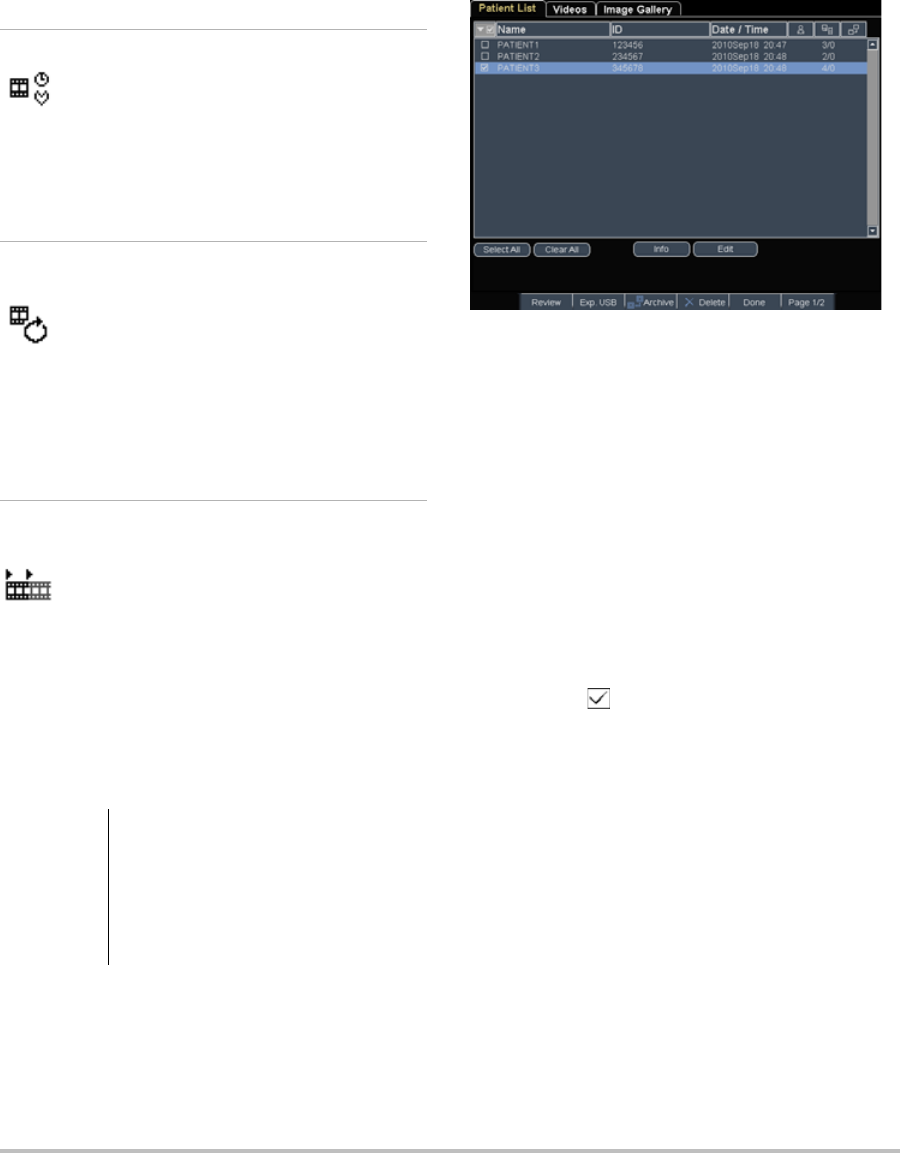
36 Images and clips
Clips options
Reviewing patient exams
Thepatientlistorganizessavedimagesandclips
inpatientexams.Youcandelete,view,print,or
archiveexams.YoucanalsocopythemtoaUSB
storagedevice.
Figure 1 Patient List
To display the patient list
1PresstheREVIEWkey.
2Ifthereisanactiveexam,selectListon‐screen.
To sort the patient list
Afterthesystemstarts,thepatientlistisarranged
bydateandtime,withthemostrecentpatientfile
first.Youcanre‐sortthepatientlistasneeded.
Selectthecolumnheadingthatyouwantto
sortby.Selectitagainifsortinginreverse
order.
Note: Thecolumnheadingisselectable.
To select patients in the patient list
Usingthetouchpad,selectthecheckboxfor
oneormorepatients.
Select Allselectsallpatients.
Todeselectpatients,selectcheckedboxesorClear
All.
To edit patient information from the patient
list
YoucaneditthepatientnameandIDfromthe
patientlistinsteadoffromthepatient
informationformiftheexamhasnotbeen
exportedorarchived.
1Inthepatientlist,selectthepatient.
Time, ECG Time and ECG share the same
location on-screen.
•With Time, capturing is based
on number of seconds. Select
the time duration.
•With ECG, capturing is based
on the number of heart beats.
Select the number of beats.
Preview On,
Preview Off
PrevOn and PrevOff turn the
preview feature on and off.
•With Prev/On, the captured
clip automatically plays
on-screen. The clip can be
trimmed, saved, or deleted.
•With Prev/Off, the clip saves
to internal storage, and the
trim and delete options are
not available.
Prospective,
Retrospective
Pro and Retro determine how
clips are captured:
•With Pro, a clip is captured
prospectively, after you press
the CLIP key.
•With Retro, a clip is captured
retrospectively, from
pre-saved data before you
press the CLIP key.
Caution: If the internal storage icon does not
appear in the system status area,
internal storage may be defective.
Contact SonoSite Technical
Support. (See “SonoSite Technical
Support” on page vii.)

Chapter 3: Imaging 37
Imaging
2SelectEdit.
3Fillintheformfields,andselectOK.
To append images and clips to a patient
exam
Althoughyoucannotaddimagesandclipstoa
patientexamthatisended,exported,orarchived,
youcanautomaticallystartanewpatientexam
thathasthesamepatientinformation.
Dependingonyourarchiver,thetwoexams
appearasonestudywhenexportedorarchived.
1Selecttheexaminthepatientlist.
2SelectAppendon‐screen.
Anewpatientinformationformappears.The
formhasthesameinformationastheexam
youselected.
To review images and clips
Youcanreviewimagesandclipsinonlyone
patientexamatatime.
1Inthepatientlist,highlightthepatientexam
whoseimagesandclipsyouwanttoreview.
2SelectReviewon‐screen.
3Select x/xtocycletotheimageorclipyou
wanttoreview.
4(ClipOnly)SelectPlay.
Theclipplaysautomaticallyafterloading.
Theloadtimedependsoncliplength.
YoucanselectPausetofreezetheclipandcan
selectaplaybackspeed 1x,1/2x,1/4x.
5Selectx/xtocycletothenextimageorclip
youwanttoview.
Toreturntothepatientlist,selectList.Toreturn
toimaging,selectDone.
Printing, exporting, and deleting images
and clips
To print an image
1Verifythataprinterisselected.See“To
configurethesystemforaprinter”on
page 19.
2Dooneofthefollowing:
•Inthepatientlist,reviewthepatient’s
images.SelectPrintwhentheimage
appears.
•Withtheimagedisplayed,presstheA
shortcutkey.
Bydefault,theAshortcutkeyprints.To
reprogramtheAandBshortcutkeys,see
“Presetssetup”onpage 22.
To print multiple images
1Verifythataprinterisselected.See“To
configurethesystemforaprinter”on
page 19.
2Dooneofthefollowing:
•Printallimagesformultiplepatients:
Selectoneormorepatientsinthepatient
list.Thenselect Print.
•Printallimagesforonepatient:Highlight
thepatientinthepatientlist,andthen
selectPrint.
WARNING: To avoid damaging the USB
storage device and losing patient
data from it, observe the following:
• Do not remove the USB storage
device or turn off the ultrasound
system while the system is
exporting.
• Do not bump or otherwise apply
pressure to the USB storage
device while it is in a USB port on
the ultrasound system. The
connector could break.

38 ECG Monitoring
Eachimageappearsbrieflyon‐screen
whileprinting.
To export patient exams to a USB storage
device
AUSBstoragedeviceisfortemporarystorageof
imagesandclips.Patientexamsshouldbe
archivedregularly.Tospecifyfileformat,see
“USBDevicessetup”onpage 23.
1InserttheUSBstoragedevice.
2Inthepatientlist,selectthepatientexamsyou
wanttoexport.
3SelectExp. USB on‐screen.AlistofUSB
devicesappears.
4SelecttheUSBstoragedevice.Ifyouwantto
hidepatientinformation,deselectInclude
patient information on images and clips.
OnlyavailableUSBdevicesareselectable.
5SelectExport.
Thefilesarefinishedexporting
approximatelyfivesecondsaftertheUSB
animationstops.RemovingtheUSBstorage
deviceorturningoffthesystemwhile
exportingmaycauseexportedfilestobe
corruptedorincomplete.Tostopin‐progress
exporting,selectCancel Export.
To delete images and clips
1Selectoneormorepatientsinthepatientlist.
2SelectDeletetodeletetheselectedpatients.A
confirmationscreenappears.
To manually archive images and clips
YoucansendpatientexamstoaDICOMprinter
orarchiver,ortoaPCusingSiteLink.DICOM
andSiteLinkareoptionalfeatures.Formore
informationaboutarchiving,seetheSiteLinkand
DICOMdocumentation.
1Selectoneormorepatientsinthepatientlist.
2SelectArchive.
To display information about a patient exam
1Onthepatientlist,selecttheexam.
2Select Info.
ECG Monitoring
ECGMonitoringisanoptionalfeatureand
requiresaSonoSiteECGcable.
To monitor ECG
1ConnecttheECGcabletotheECGconnector
ontheultrasoundsystem,mini‐dock,or
dockingsystem.
ECGMonitoringturnsonautomatically.
Note: AnexternalECGmonitormaycausealag
inthetimingoftheECGtrace,correspondingwith
the2Dimage.Biopsyguidelinesarenotavailable
whenECGisconnected.
2SelectECGon‐screen.(ECGmaybeonanother
page.ItappearsonlyiftheECGcableis
connected.)
3Selectoptionsasdesired.
WARNING: To prevent misdiagnosis, do not use
the ECG trace to diagnose cardiac
rhythms. The SonoSite ECG option
is a non-diagnostic feature.
To avoid electrical interference with
aircraft systems, do not use the ECG
cable on aircraft. Such interference
may have safety consequences.
Caution: Use only accessories recommended
by SonoSite with the system. Your
system can be damaged by
connecting an accessory not
recommended by SonoSite.
Chapter 3: Imaging 39
Imaging
ECG Monitoring options
Show/Hide Turns on and off ECG trace.
Gain Increases or decreases ECG gain.
Settings are 0-20.
Position Sets the position of the ECG trace.
Sweep Speed Settings are Slow, Med, and Fast.
Delay Displays Line and Save for clip
acquisition delay. (For instructions
to capture clips, see “To capture and
save a clip” on page 35.)
Line The position of the delay line on the
ECG trace. The delay line indicates
where the clip acquisition is
triggered.
Save Saves the current position of the
delay line on the ECG trace. (You
can change the position of the
delay line temporarily. Starting a
new patient information form or
cycling system power reverts the
delay line to the most recently
saved position.)
Select Delay to display these
options.

40 ECG Monitoring

Chapter 4: Measurements and Calculations 41
Measurements
Chapter 4: Measurements and Calculations
Youcanmeasureforquickreference,oryoucan
measurewithinacalculation.Youcanperform
generalcalculationsaswellascalculations
specifictoanexamtype.
Measurementsareperformedonfrozenimages.
Forreferencesused,seeChapter 7,“References.”
Measurements
Youcanperformbasicmeasurementsinany
imagingmodeandcansavetheimagewiththe
measurementsdisplayed.(See“Tosavean
image”onpage 35.)ExceptfortheMModeHR
measurement,theresultsdonotautomatically
savetoacalculationandthepatientreport.Ifyou
prefer,youcanfirstbeginacalculationandthen
measure.See“Performingandsaving
measurementsincalculations”onpage 45.
Someoptionsmaynotapplytoyoursystem.
Optionsavailabledependonyourconfiguration,
transducer,andexamtype.
To save a measurement to a calculation and
patient report
1Withthemeasurementactive(green),press
theCALCSkey.
2Fromthecalculationsmenu,selecta
measurementname.
Onlymeasurementnamesavailableforthe
imagingmodeandexamtypeareselectable.
3Savethecalculation.(See“Tosavea
calculation”onpage 45.)
Tostartacalculationbeforemeasuring,see
“Performingandsavingmeasurementsin
calculations”onpage 45.
Working with calipers
Whenmeasuring,youworkwithcalipers,often
inpairs.Resultsbasedonthecalipers’position
appearatthebottomofthescreen.Theresults
updateasyourepositionthecalipersbyusingthe
touchpad.Intracemeasurements,theresults
appearafteryoucompletethetrace.
Outsideacalculation,youcanaddcalipersby
pressingtheCALIPERkey.Youcanhavemultiple
setsofcalipersandcanswitchfromonesetto
another,repositioningthemasneeded.Eachset
showsthemeasurementresult.Theactive
calipersandmeasurementresultarehighlighted
green.Ameasurementiscompletewhenyou
finishmovingitscalipers.
Withinacalculation,calipersappearwhenyou
selectfromthecalculationsmenu.(See“Toselect
fromthecalculationsmenu”onpage 45.)
Foranaccuratemeasurement,accurate
placementofcalipersisessential.
To switch the active calipers
Dooneofthefollowing:
•Toswitchtheactivecaliperwithinaset,
presstheSELECTkey.
•Toswitchtheactivesetwhenmeasuring
outsideacalculation,selectSwitch
on‐screen.
To delete or edit a measurement
Withthemeasurementactive(highlighted),
dooneofthefollowing:
•Todelete,selectDeleteon‐screen.
•Toedit,usethetouchpadtomovethe
calipers.
Note: Tracemeasurementscannotbeeditedonceset.
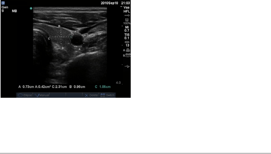
42 Measurements
To improve precision of caliper placement
Doanyofthefollowing:
•Adjustthedisplayformaximum
sharpness.
•Useleadingedges(closesttothe
transducer)orbordersforstartingand
stoppingpoints.
• Maintainaconsistenttransducer
orientationforeachtypeofmeasurement.
•Makesurethattheareaofinterestfillsas
muchofthescreenaspossible.
•(2D)Minimizethedepth,orzoom.
2D measurements
Thebasicmeasurementsthatyoucanperformin
2Dimagingareasfollows:
•Distanceincm
•Areaincm2
• Circumferenceincm
Youcanalsomeasureareaorcircumferenceby
tracingmanually.
Figure 1 2D image with two distance and one
circumference measurement
Youcanperformacombinationofdistance,area,
circumference,andmanualtracemeasurements
atonetime.Thetotalnumberpossibledepends
ontheirorderandtype.
To measure distance (2D)
Youcanperformuptoeightdistance
measurementsona2Dimage.
1Onafrozen2Dimage,presstheCALIPERkey.
Apairofcalipersappears,connectedbya
dottedline.
2Usingthetouchpad,positionthefirstcaliper,
andthenpresstheSELECTkey.
Theothercaliperbecomesactive.
3Usingthetouchpad,positiontheothercaliper.
Ifyoumovethecalipersclosetogether,they
shrinkandthedottedlinedisappears.
See“Tosaveameasurementtoacalculationand
patientreport”onpage 41.
To measure area or circumference (2D)
1Onafrozen2Dimage,presstheCALIPERkey.
2SelectEllipseon‐screen.
Note: Ifyouexceedtheallowednumberof
measurements,Ellipseisnotavailable.
3Usethetouchpadtoadjustthesizeand
positionoftheellipse.TheSELECTkeytoggles
betweenpositionandsize.
See“Tosaveameasurementtoacalculationand
patientreport”onpage 41.
To trace manually (2D)
1Onafrozen2Dimage,presstheCALIPERkey.
2SelectManualon‐screen.
Note: Ifyouexceedtheallowednumberof
measurements,Manualisnotavailable.
3Usingthetouchpad,positionthecaliper
whereyouwanttobegin.

Chapter 4: Measurements and Calculations 43
Measurements
4PresstheSELECTkey.
5Usingthetouchpad,completethetrace,and
presstheSETkey.
See“Tosaveameasurementtoacalculationand
patientreport”onpage 41.
M Mode measurements
Thebasicmeasurementsthatyoucanperformin
MModeimagingareasfollows:
•Distanceincm/Timeinseconds
•HeartRate(HR)inbeatsperminute(bpm)
Thetimescaleabovethetracehassmallmarksat
200 msintervalsandlargemarksatone‐second
intervals.
To measure distance (M Mode)
Youcanperformuptofourdistance
measurementsonanimage.
1OnafrozenMModetrace,presstheCALIPER
key.
Asinglecaliperappears.
2Usingthetouchpad,positionthecaliper.
3PresstheSELECTkeytodisplaythesecond
caliper.
4Usingthetouchpad,positionthesecond
caliper.
See“Tosaveameasurementtoacalculationand
patientreport”onpage 41.
To measure heart rate (M Mode)
1OnafrozenMModetrace,presstheCALIPER
key.
2SelectHRon‐screen.
Averticalcaliperappears.
3Usingthetouchpad,positionthevertical
caliperatthepeakoftheheartbeat.
4PresstheSELECTkey.
Asecondverticalcaliperappears.
5Usingthetouchpad,positionthesecond
verticalcaliperatthepeakofthenext
heartbeat.
See“Tosaveameasurementtoacalculationand
patientreport”onpage 41.Savingtheheartrate
measurementtothepatientreportoverwrites
anyheartrateenteredonthepatientinformation
form.
Seealso“Tomeasurefetalheartrate(MMode)”
onpage 63.
Doppler measurements
Thebasicmeasurementsthatyoucanperformin
DopplerimagingareVelocity(cm/s),Pressure
Gradient,ElapsedTime,+/xRatio,Resistive
Index (RI),andAcceleration.Youcanalsotrace
manuallyorautomatically.
ForDopplermeasurements,theDopplerscale
mustbesettocm/s.See“Presetssetup”on
page 22.
To measure Velocity (cm/s) and Pressure
Gradient (Doppler)
1OnafrozenDopplerspectraltrace,pressthe
CALIPERkey.
Asinglecaliperappears.
2Usingthetouchpad,positionthecalipertoa
peakvelocitywaveform.
Thismeasurementinvolvesasinglecaliperfrom
thebaseline.
See“Tosaveameasurementtoacalculationand
patientreport”onpage 41.

44 Measurements
To measure Velocities, Elapsed Time, +/x
Ratio, Resistive Index (RI), and Acceleration
(Doppler)
1OnafrozenDopplerspectraltrace,pressthe
CALIPERkey.
Asinglecaliperappears.
2Usingthetouchpad,positionthecalipertoa
peaksystolicwaveform.
3PresstheSELECTkey.
Asecondcaliperappears.
4Usingthetouchpad,positionthesecond
caliperattheenddiastoleonthewaveform.
See“Tosaveameasurementtoacalculationand
patientreport”onpage 41.
To measure time duration (Doppler)
1OnaDopplerspectraltrace,presstheCALIPER
key.
2PressTimeon‐screen.
3Averticalcaliperappears.
4Usingthetouchpad,positionthecaliper
wheredesired,andpresstheSELECTkey.
5Asecondcaliperappears.
6Usingthetouchpad,positionthesecond
caliperwheredesired,andpresstheSELECT
key.
To trace manually (Doppler)
1OnafrozenDopplerspectraltrace,pressthe
CALIPERkey.
2SelectManualon‐screen.
Asinglecaliperappears.
3Usingthetouchpad,positionthecaliperatthe
beginningofthedesiredwaveform,andpress
theSELECTkey.
Ifcalipersarenotpositionedcorrectly,the
resultisinaccurate.
4Usingthetouchpad,tracethewaveform.
Tomakeacorrection,selectUndoon‐screen,
backtrackwiththetouchpad,orpressthe
BACKSPACEkey.
5PresstheSETkey.
Themeasurementresultsappear.
See“Tosaveameasurementtoacalculationand
patientreport”onpage 41.
To trace automatically (Doppler)
Aftertracingautomatically,confirmthatthe
system‐generatedboundaryiscorrect.Ifyouare
notsatisfiedwiththetrace,obtainahigh‐quality
Dopplerspectraltraceimage,ortracemanually.
(See“Totracemanually(Doppler)”onpage 44.)
1OnafrozenDopplerspectraltrace,pressthe
CALIPERkey.
2SelectAutoon‐screen.
Averticalcaliperappears.
3Usingthetouchpad,positionthecaliperatthe
beginningofthewaveform.
Ifcalipersarenotpositionedcorrectly,the
calculationresultisinaccurate.
4PresstheSELECTkey.
Asecondverticalcaliperappears.
5Usingthetouchpad,positionthesecond
caliperattheendofthewaveform.
6PresstheSETkey.
Themeasurementresultsappear.
See“Tosaveameasurementtoacalculationand
patientreport”onpage 41.
Automatic trace results
Dependingontheexamtype,theresultsfrom
automatictracingincludethefollowing:
•VelocityTimeIntegral(VTI)
•PeakVelocity(Vmax)

Chapter 4: Measurements and Calculations 45
Measurements
•MeanPressureGradient(PGmean)
•MeanVelocityonPeakTrace(Vmean)
•PressureGradient(PGmax)
•CardiacOutput(CO)
•PeakSystolicVelocity(PSV)
•TimeAverageMean(TAM)*
•+/×orSystolic/Diastolic(S/D)
•PulsatilityIndex(PI)
•EndDiastolicVelocity(EDV)
• AccelerationTime(AT)
•ResistiveIndex(RI)
•TimeAveragePeak(TAP)
• GateDepth
General calculations
Withincalculations,youcansavemeasurement
resultstothepatientreport.Youcandisplay,
repeat,anddeletemeasurementsfroma
calculation.Somemeasurementscanbedeleted
directlyfromthepatientreportpages.See
“Patientreport”onpage 68.
Calculationpackagesdependonexamtypeand
transducer.
Calculations menu
Thecalculationsmenucontainsmeasurements
availablefortheimagingmodeandexamtype.
Afteryouperformandsaveameasurement,the
resultsavestothepatientreport.(See“Patient
report”onpage 68.)Also,acheckmarkappears
nexttothemeasurementnameinthecalculations
menu.Ifyouhighlightthecheckedmeasurement
name,theresultsappearbelowthemenu.Ifyou
repeatthemeasurement,theresultsbelowthe
menureflecteitherthelastmeasurementorthe
average,dependingonthemeasurement.
Menuitemsfollowedbyellipses(...)have
subentries.
To select from the calculations menu
1Onafrozenimage,presstheCALCSkey.
Thecalculationsmenuappears.
2Usingthetouchpadorarrowkeys,highlight
thedesiredmeasurementname.
Todisplayadditionalmeasurementnames,
highlightNext,Prev,orameasurementname
thathasellipses(...).ThenpresstheSELECT
key.
Onlymeasurementnamesavailableforthe
imagingmodeareselectable.
3PresstheSELECTkey.
Toclosethecalculationsmenu,presstheCALCS
keyonce(ifthemenuisactive)ortwice(ifthe
menuisinactive).
Performing and saving measurements
in calculations
Inperformingameasurementwithina
calculation,youselectfromthecalculations
menu,positionthecalipersthatappear,andthen
savethecalculation.Unlikemeasurements
performedoutsideacalculation,thecalipers
appearbyselectingfromthecalculationsmenu,
notbypressingtheCALIPERkey.Thetypeof
calipersthatappeardependsonthe
measurement.
To save a calculation
Dooneofthefollowing:
•Savethecalculationonly:Pressthe
SAVE CALCkey,orselectSaveon‐screen.
Thecalculationsavestothepatientreport.
Tosavetheimagewiththemeasurements
displayed,see“Tosaveanimage”on
page 35.
•Saveboththeimageandcalculation:Press
theSAVE keyiftheSAVEkeyfunctionality

46 General calculations
issettoImage/Calcs.(See“Presetssetup”
onpage 22.)
Thecalculationsavestothepatientreport,
andtheimagesavestointernalstorage
withthemeasurementsdisplayed.
Displaying, repeating, and deleting
saved measurements in calculations
To display a saved measurement
Dooneofthefollowing:
•Highlightthemeasurementnameinthe
calculationsmenu.Theresultappears
belowthemenu.
Openthepatientreport.See“Patientreport”on
page 68.
To repeat a saved measurement
1Highlightthemeasurementnameinthe
calculationsmenu.
2PresstheSELECTkeyortheCALIPERkey.
3Performthemeasurementagain.
Thenewresultsappearon‐screeninthe
measurementandcalculationsdataarea.(See
“Screenlayout”onpage 7.)Youcancompare
themtothesavedresultsbelowthemenu.
4Tosavethenewmeasurement,pressthe
SAVE CALCkey.
Thenewmeasurementsavestothepatient
reportandoverwritesthepreviouslysaved
measurement.
To delete a saved measurement
1Selectthemeasurementnamefromthe
calculationsmenu.
2SelectDeleteon‐screen.
Themeasurementlastsavedisdeletedfrom
thepatientreport.Ifitistheonly
measurement,thecheckmarkisdeletedfrom
thecalculationsmenu.
Somemeasurementscanbedeleteddirectlyfrom
thepatientreportpages.See“Patientreport”on
page 68.
EMED calculations
TheresultsfromEMEDcalculations
automaticallyappearintheEMEDworksheets.
AllEMEDcalculationsareavailableforeach
examtype.
To perform an EMED calculation:
1PresstheCALCSkey.
2SelectEMEDon‐screen.
ThecalculationsmenubecomestheEMED
calculationsmenu.
3Selectthecalculationname.
4Performadistancemeasurement.
5Savethemeasurement.
Toreturntothecalculationsmenu,selectCalcs
on‐screen.
Percent reduction calculations
WARNING: To avoid incorrect calculations,
verify that the patient information,
date, and time settings are accurate.
To avoid misdiagnosis or harming
the patient outcome, start a new
patient information form before
starting a new patient exam and
performing calculations. Starting a
new patient information form clears
the previous patient’s data. The
previous patient’s data will be
combined with the current patient
if the form is not first cleared. See
“To create a new patient
information form” on page 34.
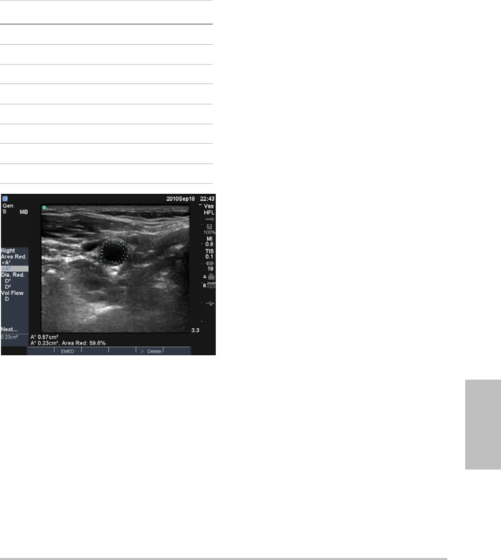
Chapter 4: Measurements and Calculations 47
Measurements
Figure 2 Percent area reduction calculation of right
carotid bulb
To calculate percent area reduction
Thepercentareareductioncalculationinvolves
twomanualtracemeasurements.
1Onafrozen2Dimage,presstheCALCSkey.
2DothefollowingforA1andthenforA2:
aFromthecalculationsmenu,selectthe
measurementnameunderArea Red.
bUsingthetouchpad,movethecaliperto
thetracestartingpoint,andpressthe
SELECTkey.
cUsingthetouchpad,tracethedesiredarea.
Tomakeacorrection,selectUndo
on‐screenorpresstheBACKSPACEkey.
dCompletethetrace,andpresstheSETkey.
eSavethecalculation.See“Tosavea
calculation”onpage 45.
Thepercentareareductionresultappears
on‐screeninthemeasurementandcalculation
dataareaandinthepatientreport.
To calculate percent diameter reduction
1Onafrozen2Dimage,presstheCALCSkey.
2DothefollowingforD1andthenforD2:
aFromthecalculationsmenu,selectthe
measurementnameunderDia Red.
bPositionthecalipers.(See“Workingwith
calipers”onpage 41.)
cSavethecalculation.See“Tosavea
calculation”onpage 45.
Thepercentdiameterreductionresultappearsin
themeasurementandcalculationdataareaand
inthepatientreport.
Transducer Exam Types
C11x Abdomen
C60x Abdomen
HFL38x IMT, Small Parts, Vascular
L25x Vascular, Muscle
L38x IMT, Small Parts, Vascular
P10x Abdomen
P21x Abdomen
SLAx Muscle, Vascular

48 General calculations
Volume calculations To calculate volume
Thevolumecalculationinvolvesthree2D
distancemeasurements:D1,D2,andD3.Afterall
measurementsaresaved,theresultappears
on‐screenandinthepatientreport.
Dothefollowingforeachimageyouneedto
measure:
aOnthefrozen2Dimage,presstheCALCS
key.
bDothefollowingforeachmeasurement
youneedtotake:
iFromthecalculationsmenu,selectthe
measurementnameunderVolume.(If
VolumeisnotavailableinaGynexam,
selectGynandthenselectVolume.)
ii Positionthecalipers.(See“Working
withcalipers”onpage 41.)
iii Savethemeasurement.See“Tosavea
calculation”onpage 45.
Volume flow calculations
WARNING: To avoid incorrect calculations,
verify that the patient information,
date, and time settings are
accurate.
To avoid misdiagnosis or harming
the patient outcome, start a new
patient information form before
starting a new patient exam and
performing calculations. Starting a
new patient information form
clears the previous patient’s data.
The previous patient’s data will be
combined with the current patient
if the form is not first cleared. See
“To create a new patient
information form” on page 34.
Transducer Exam Types
C11x Abdomen, Nerve
C60x Abdomen, Gyn, Nerve
HFL38x Breast, Nerve, Small Parts,
Vascular
ICTx Gyn
L25x Muscle, Nerve, Vascular,
Superficial,
L38x Breast, Nerve, Small Parts,
Vascular
P10x Abdomen, Neonatal
P21x Abdomen
SLAx Muscle, Nerve, Superficial,
Vascular
WARNING: To avoid incorrect calculations,
verify that the patient information,
date, and time settings are accurate.
To avoid misdiagnosis or harming
the patient outcome, start a new
patient information form before
starting a new patient exam and
performing calculations. Starting a
new patient information form clears
the previous patient’s data. The
previous patient’s data will be
combined with the current patient
if the form is not first cleared. See
“To create a new patient
information form” on page 34.

Chapter 4: Measurements and Calculations 49
Measurements
Thefollowingtableshowsthemeasurements
requiredtocompletethevolumeflow
calculation.Fordefinitionsofacronyms,see
“Glossary”onpage 157.
Botha2DandaDopplermeasurementare
requiredforthevolumeflowcalculation.The
Dopplersamplevolumeshouldcompletely
insonatethevessel.
Considerthefollowingfactorswhenperforming
volumeflowmeasurements:
•Usersshouldfollowcurrentmedicalpractice
forvolumeflowcalculationapplications.
•Theaccuracyofthevolumeflowcalculation
largelydependsontheuser.
•Thefactorsidentifiedintheliteraturethat
affecttheaccuracyareasfollows:
•Usingthediametermethodfor2Darea
•Difficultyensuringuniforminsonationof
thevessel.
Thesystemislimitedtothefollowing
samplevolumesizes:
• C11xtransducer:1,2,3GateSize(mm)
• C60xandP10xtransducers:2,3,5,7,
10,12GateSize(mm)
•HFL38x,L25x,L38x,andSLAx
transducers:1,3,5,7,10,12GateSize
(mm)
• P21xtransducer:2,3,5,7,11.5,14Gate
Size(mm)
•Precisioninplacingthecaliper
• Accuracyinanglecorrection
Theconsiderationsanddegreeofaccuracyfor
volumeflowmeasurementsandcalculationsare
discussedinthefollowingreference:
Allan,PaulL.etal.ClinicalDopplerUltrasound,
4thEd.,HarcourtPublishersLimited,(2000)
36‐38.
To calculate volume flow
1Performthe2Dmeasurement:
aOnafrozenfull‐screen2Dimageorduplex
image,presstheCALCSkey.
bFromthecalculationsmenu,selectD
(distance)underVol Flow.
cPositionthecalipers.(See“Workingwith
calipers”onpage 41.)
dSavethecalculation.See“Tosavea
calculation”onpage 45.
2PerformtheDopplermeasurement:
aOnafrozenDopplerspectraltrace,press
theCALCSkey.
bFromthecalculationsmenu,selectTAM
underVol Flow.
Averticalcaliperappears.
Transducer Exam Types
C11x Abdomen
C60x Abdomen
HFL38x Vascular
L25x Vascular
L38x Vascular
P10x Abdomen
P21x Abdomen
SLAx Vascular
Volume Flow Calculations
Menu
Heading
Measurement
(Imaging
Mode)
Calculation
Result
Vol Flow D (2D)
TAM (Doppler)
VF (Volume
Flow l/min)

50 Exam-based calculations
cUsingthetouchpad,positionthevertical
caliperatthebeginningofthewaveform.
Ifcalipersarenotpositionedcorrectly,the
calculationresultisinaccurate.
dPresstheSELECTkeytodisplayasecond
verticalcaliper.
eUsingthetouchpad,positionthesecond
verticalcaliperattheendofthewaveform.
fPresstheSETkeytocompletethetraceand
todisplaytheresults.
gSavethecalculation.See“Tosavea
calculation”onpage 45.
Todisplaythevolumeflowcalculation,see
“Patientreport”onpage 68.
Exam-based calculations
Inadditiontothegeneralcalculations,thereare
calculationsspecifictotheCardiac,Gynecology
(Gyn),IMT,OB,Orbital,SmallParts,Transcranial
Doppler(TCD),andVascularexamtypes.
Cardiac calculations
Thefollowingtableshowsthemeasurements
requiredtocompletedifferentcardiac
calculations.Fordefinitionsofacronyms,see
“Glossary”onpage 157.
Cardiac Calculations
WARNING: To avoid incorrect calculations,
verify that the patient information,
date, and time settings are accurate.
To avoid misdiagnosis or harming
the patient outcome, start a new
patient information form before
starting a new patient exam and
performing calculations. Starting a
new patient information form clears
the previous patient’s data. The
previous patient’s data will be
combined with the current patient
if the form is not first cleared. See
“To create a new patient
information form” on page 34.
Transducer Exam Type
D2x Cardiac
P10x Cardiac
P21x Cardiac
TEEx Cardiac
Menu
Heading
Cardiac
Measurements
(Imaging Mode)
Calculation
Results
LV…LVd RVW (2D)
RVD (2D)
IVS (2D)
LVD (2D)
LVPW (2D)
CO
EF
SV
LVESV
LVEDV
IVSFT
LVPWFT
LVDFS
CI
SI
…LVs RVW (2D)
RVD (2D)
IVS (2D)
LVD (2D)
LVPW (2D)
HRa needed for
CO & CI
Ao/LA Ao (2D or
MMode)
Ao
LA/Ao
AAo (2D) AAo
LA (2D or
MMode)
LA
LA/Ao
LVOT D (2D) LVOT D
LVOT area

Chapter 4: Measurements and Calculations 51
Measurements
ACS (M Mode) ACS
LVET (M Mode) LVET
MV EF:Slope
(M Mode)
EF SLOPE
EPSS (M Mode) EPSS
LV…LVd RVW (M Mode)
RVD (M Mode)
IVS (M Mode)
LVD (M Mode)
LVPW (M Mode)
CO
EF
SV
LVESV
LVEDV
IVSFT
LVPWFT
LVDFS
CI
SI
LV Mass
…LVs RVW (M Mode)
RVD (M Mode)
IVS (M Mode)
LVD (M Mode)
LVPW (M Mode)
HR HRa
Area AV (2D) AV Area
MV (2D) MV Area
LV Vol
(EF)
A4Cd (2D)
A4Cs (2D)
A2Cd (2D)
A2Cs (2D)
LV Vol
LV Area
EF
CO
SV
CI
SI
Biplane
LV mass Epi (2D)
Endo (2D)
Apical (2D)
LV Mass
Epi Area
Endo Area
D Apical
Menu
Heading
Cardiac
Measurements
(Imaging Mode)
Calculation
Results
PISA Ann D (2D)
Radius (Color)
MR/VTI (Doppler)
MV/VTI (Doppler)
PISA Area
ERO
MV Rate
Regurgitant
Volume
Regurgitant
Fraction
Qp/Qs LVOT D (2D)
RVOT D (2D)
LVOT VTI
(Doppler)
RVOT VTI
(Doppler)
D
VTI
VMax
PGmax
Vmean
PGmean
SV
Qp/Qs
TDI (Wall) e’ and a’
(Doppler)
(Wall) e’ and a’
(Doppler)
(Wall) e’ and a’
(Doppler)
(Wall) e’ and a’
(Doppler)
(Wall) ‘e and a’
(Doppler)
E(MV)/e’ ratio
Menu
Heading
Cardiac
Measurements
(Imaging Mode)
Calculation
Results

52 Exam-based calculations
P. Vein A (Doppler) VMax
Adur (Doppler) time
S (Doppler) VMax
S/D ratio
D (Doppler)
MV E (Doppler)
A (Doppler)
E
E PG
A
A PG
E:A
Adur (Doppler) time
PHT (Doppler) PHT
MVA
Decel time
VTI (Doppler) VTI
Vmax
PGmax
Vmean
PGmean
IVRT (Doppler) time
MV…MR dP:dTb (CW
Doppler)
dP:dT
Menu
Heading
Cardiac
Measurements
(Imaging Mode)
Calculation
Results
AV Vmax (Doppler) Vmax
PGmax
VTI (Doppler) VTI
Vmax
PGmax
Vmean
PGmean
VTI or Vmax from
LVOT (Doppler)
VTI or Vmax from
AV (Doppler)
AVA
Ao/LA LVOT D (2D)
AV VTI (Doppler) SV
Ao/LA LVOT D (2D)
AV VTI (Doppler) CO
Ao/LA LVOT D (2D)
HR HRa
LVOT Vmax (Doppler) Vmax
PGmax
VTI (Doppler) VTI
Vmax
PGmax
Vmean
PGmean
AV…AI PHT (slope)
(Doppler)
AI PHT
AI slope
Menu
Heading
Cardiac
Measurements
(Imaging Mode)
Calculation
Results

Chapter 4: Measurements and Calculations 53
Measurements
To measure LVd and LVs
1Onafrozen2DimageorMModetrace,press
theCALCSkey.
2Fromthecalculationsmenu,selectthe
measurementname.
3Positiontheactive(green)caliperatthe
startingpoint.(See“Workingwithcalipers”
onpage 41.)
4PresstheSELECTkey,andpositionthesecond
caliper.
5PresstheSELECTkey.
Anothercaliperappears,andthecalculations
menuhighlightsthenextmeasurementname.
6Positionthecaliper,andpresstheSELECTkey.
Repeatforeachmeasurementnameinthe
calculationgroup.
EachtimeyoupresstheSELECTkey,another
caliperappears,andthecalculationsmenu
highlightsthenextmeasurementname.
7Savethecalculation.(See“Tosavea
calculation”onpage 45.)
To measure Ao, LA, AAo, or LVOT D
1Onafrozen2DimageorMModetrace,press
theCALCSkey.
2Fromthecalculationsmenu,selectthe
measurementname.
3Positionthecalipers.(See“Workingwith
calipers”onpage 41.)
4Savethecalculation.(See“Tosavea
calculation”onpage 45.)
To calculate LV Volume (Simpson’s Rule)
1Onafrozen2Dimage,presstheCALCSkey.
2Dothefollowingforeachmeasurement:
aFromthecalculationsmenu,selectthe
desiredviewandphase.
bPositionthecaliperatthemitralannulus,
andpresstheSELECTkeytostartthetrace.
TV TRmax (Doppler) Vmax
PGmax
E (Doppler)
A (Doppler)
E
E PG
A
A PG
E:A
PHT (Doppler) PHT
MVA
Decel time
VTI (Doppler) VTI
Vmax
PGmax
Vmean
PGmean
RA pressurecRVSP
PV Vmax (Doppler) Vmax
PGmax
VTI (Doppler)
AT (Doppler)
VTI
Vmax
PGmax
Vmean
PGmean
AT
a. You can enter the HR measurement three ways: Patient
information form, Doppler measurement (See “To
calculate Heart Rate (HR)” on page 57), or M Mode
measurement (See “To measure heart rate (M Mode)” on
page 43).
b. Performed at 100 cm/s and 300 cm/s.
c. Specified on the cardiac patient report. See “To delete a
vascular or cardiac measurement” on page 69.
Menu
Heading
Cardiac
Measurements
(Imaging Mode)
Calculation
Results

54 Exam-based calculations
cUsingthetouchpad,tracetheleft
ventricular(LV)cavity.
Tomakeacorrection,selectUndoon‐screen
orpresstheBACKSPACEkey.
dCompletethetrace,andpresstheSETkey.
eSavethecalculation.(See“Tosavea
calculation”onpage 45.)
To calculate MV or AV area
1Onafrozen2Dimage,presstheCALCSkey.
2Inthecalculationsmenu,locateArea,and
thenselectMVorAV.
3Positionthecaliperwhereyouwanttobegin
thetrace,andpresstheSELECTkey.
4Usingthetouchpad,tracethedesiredarea.
Tomakeacorrection,selectUndoon‐screenor
presstheBACKSPACEkey.
5Completethetrace,andpresstheSETkey.
6Savethecalculation.(See“Tosavea
calculation”onpage 45.)
To calculate LV Mass
1Onafrozen2Dimage,presstheCALCSkey.
2Inthecalculationsmenu,locateLV Mass.
3DothefollowingforEPIandthenforEndo:
aSelectthemeasurementnamefromthe
calculationsmenu.
bPositionthecaliperwhereyouwantto
beginthetrace,andpresstheSELECTkey.
cUsingthetouchpad,tracethedesiredarea.
Tomakeacorrection,selectUndo
on‐screenorpresstheBACKSPACEkey.
dCompletethetrace,andpresstheSETkey.
eSavethecalculation.(See“Tosavea
calculation”onpage 45.).
4SelectApical fromthecalculationsmenu.
5Positioningthecalipers,measurethe
ventricularlength.(See“Workingwith
calipers”onpage 41.)
6Savethecalculation.
To measure peak velocity
Foreachcardiacmeasurement,thesystemsaves
uptofiveindividualmeasurementsand
calculatestheiraverage.Ifyoutakemorethan
fivemeasurements,themostrecentmeasurement
replacesthefifthone.Ifyoudeleteasaved
measurementfromthepatientreport,thenext
measurementtakenreplacesthedeletedonein
thepatientreport.Themostrecentlysaved
measurementappearsatthebottomofthe
calculationsmenu.
1OnafrozenDopplerspectraltrace,pressthe
CALCSkey.
2Fromthecalculationsmenu,selectMV,TV,or
TDI,orP. V e i n .
3Dothefollowingforeachmeasurementyou
wanttotake:
aSelectthemeasurementnamefromthe
calculationsmenu.
bPositionthecalipers.(See“Workingwith
calipers”onpage 41.)
cSavethecalculation.(See“Tosavea
calculation”onpage 45.)
To calculate Velocity Time Integral (VTI)
Note: Thiscalculationcomputesotherresultsin
additiontoVTI.Seethetable“CardiacCalculations”
onpage 50.
1OnafrozenDopplerspectraltrace,pressthe
CALCSkey.
2Fromthecalculationsmenu,selectVTI under
MV,AV,TV,PV,orLVOT.
3Positionthecaliperatthestartofthe
waveform,andpresstheSELECTkeytostart
thetrace.

Chapter 4: Measurements and Calculations 55
Measurements
4Usingthetouchpad,tracethewaveform.
Tomakeacorrection,selectUndoon‐screen,
backtrackwiththetouchpad,orpressthe
BACKSPACEkey.
5PresstheSETkeytocompletethetrace.
6Savethecalculation.(See“Tosavea
calculation”onpage 45.)
Forinformationontheautomatictracetool,see
“Totraceautomatically(Doppler)”onpage 44.
To calculate Right Ventricular Systolic
Pressure (RVSP)
1OnafrozenDopplerspectraltrace,pressthe
CALCSkey.
2Fromthecalculationsmenu,selectTVand
thenselectTRmax.
3Positionthecaliper.(See“Workingwith
calipers”onpage 41.)
4Savethecalculation.(See“Tosavea
calculation”onpage 45.)
5ToadjusttheRApressure,see“Todeletea
vascularorcardiacmeasurement”onpage 69.
ChangingtheRApressurefromthedefault5
affectstheRVSPcalculationinthepatient
report.
To calculate Pressure Half Time (PHT) in MV,
AI, or TV
1OnafrozenDopplerspectraltrace,pressthe
CALCSkey.
2Fromthecalculationsmenu,selectMV, AV,or
TV,andthenselectPHT.
3Positionthefirstcaliperatthepeak,andpress
theSELECTkey.
Asecondcaliperappears.
4Positionthesecondcaliper:
•InMV,positionthecaliperalongtheEF
slope.
•InAV,positionthecaliperattheend
diastole.
5Savethecalculation.(See“Tosavea
calculation”onpage 45.)
To calculate Proximal Isovelocity Surface
Area (PISA)
ThePISAcalculationrequiresameasurementin
2D,ameasurementinColor,andtwo
measurementsinDopplerspectraltrace.Afterall
measurementsaresaved,theresultappearsin
thepatientreport.
1MeasurefromAnnD(2D):
aOnafrozen2Dimage,presstheCALCSkey.
bFromthecalculationsmenu,locatePISA,
andthenselectAnn D.
cPositionthecalipers.(See“Workingwith
calipers”onpage 41.)
dSavethecalculation.(See“Tosavea
calculation”onpage 45.)
2MeasurefromRadius(Color):
aOnafrozenColorimage,presstheCALCS
key.
bFromthecalculationsmenu,selectRadius.
cPositionthecalipers.
dSavethecalculation.
3OnafrozenDopplerspectraltrace,pressthe
CALCSkey.
4DothefollowingtomeasurefromMRVTI
andagaintomeasurefromMVVTI(Doppler):
aFromthecalculationsmenu,selectPISA
andthenselectMR VTI orMV VTI.
bPositionthecaliperatthestartofthe
waveform,andpresstheSELECTkeyto
startthetrace.
cUsingthetouchpad,tracethewaveform.

56 Exam-based calculations
Tomakeacorrection,selectUndo
on‐screen,backtrackwiththetouchpad,or
presstheBACKSPACEkey.
dPresstheSETkeytocompletethetrace.
eSavethecalculation.
Forinformationontheautomatictracetool,see
“Totraceautomatically(Doppler)”onpage 44.
To calculate Isovolumic Relaxation Time
(IVRT)
1OnafrozenDopplerspectraltrace,pressthe
CALCSkey.
2Fromthecalculationsmenu,selectMVand
thenselectIVRT.
Averticalcaliperappears.
3Usingthetouchpad,positionthecaliperatthe
aorticvalveclosure.
4PresstheSELECTkey.
Asecondverticalcaliperappears.
5Usingthetouchpad,positionthesecond
caliperatonsetofmitralinflow.
6Savethecalculation.(See“Tosavea
calculation”onpage 45.)
To calculate Delta Pressure: Delta Time
(dP:dT)
ToperformthedP:dTmeasurements,theCW
Dopplerscalemustincludevelocitiesof300 cm/s
orgreateronthenegativesideofthebaseline.
(See“Spectraltraceoptions”onpage 29.)
1OnafrozenCWDopplerspectraltrace,press
theCALCSkey.
2Fromthecalculationsmenu,selectMV,and
thenselectdP:dT.
Ahorizontaldottedlinewithanactivecaliper
appearsat100cm/s.
3Positionthefirstcaliperalongthewaveform
at100cm/s.
4PresstheSELECTkey.
Asecondhorizontaldottedlinewithanactive
caliperappearsat300cm/s.
5Positionthesecondcaliperalongthe
waveformat300cm/s.
6Savethecalculation.(See“Tosavea
calculation”onpage 45.)
To calculate Aortic Valve Area (AVA)
TheAVAcalculationrequiresameasurementin
2DandtwomeasurementsinDoppler.Afterthe
measurementsaresaved,theresultappearsin
thepatientreport.
1MeasurefromLVOT(2D):
aOnafrozen2Dimage,presstheCALCSkey.
bFromthecalculationsmenu,selectLVOT D.
cPositionthecalipers.(See“Workingwith
calipers”onpage 41.)
dSavethecalculation.(See“Tosavea
calculation”onpage 45.)
2MeasurefromLVOT,andthenmeasurefrom
AV(Doppler):
•ForVmax,see“Tomeasurepeakvelocity”
onpage 54.Fromthecalculationsmenu,
selectAV,selectsamplesite,andthen
selectVmax.
•ForVTI,see“TocalculateVelocityTime
Integral(VTI)”onpage 54.Fromthe
calculationsmenu,selectAV,selectsample
site,andthenselectVTI.
To calculate Qp/Qs
TheQp/Qscalculationrequirestwo
measurementsin2Dandtwomeasurementsin
Doppler.Afterthemeasurementsaresaved,the
resultappearsinthepatientreport.
1Onafrozen2Dimage,presstheCALCSkey.
2DothefollowingtomeasurefromLVOTD
andagaintomeasurefromRVOT D:

Chapter 4: Measurements and Calculations 57
Measurements
aFromthecalculationsmenu,locateQp/Qs
andthenselectLVOT D or RVOT D.
bPositionthecalipers.(See“Workingwith
calipers”onpage 41.)
cSavethecalculation.(See“Tosavea
calculation”onpage 45.)
3OnafrozenDopplerspectraltrace,pressthe
CALCSkey.
4DothefollowingtomeasurefromLVOTVTI
andagaintomeasurefromRVOTVTI:
aFromthecalculationsmenu,selectQp/Qs
andthenselectLVOT VTI or RVOT VTI.
bPresstheSELECTkeytostartthetrace.
cUsingthetouchpad,tracethewaveform.
Tomakeacorrection,selectUndo
on‐screen,backtrackwiththetouchpad,or
presstheBACKSPACEkey.
dPresstheSETkeytocompletethetrace.
eSavethecalculation.(See“Tosavea
calculation”onpage 45.)
Forinformationontheautomatictracetool,see
“Totraceautomatically(Doppler)”onpage 44.
To calculate Stroke Volume (SV) or Stroke
Index (SI)
TheSVandSIcalculationsrequirea
measurementin2Dandameasurementin
Doppler.SIalsorequiresBodySurfaceArea
(BSA).Afterthemeasurementsaresaved,the
resultappearsinthepatientreport.
1(SIOnly)FillintheHeightandWeightfields
onthepatientinformationform.TheBSAis
calculatedautomatically.(See“Tocreatea
newpatientinformationform”onpage 34.)
2MeasurefromLVOT(2D):
aOnafrozen2Dimage,presstheCALCSkey.
bFromthecalculationsmenu,selectLVOT D.
cPositionthecalipers.(See“Workingwith
calipers”onpage 41.)
dSavethecalculation.(See“Tosavea
calculation”onpage 45.)
3Measurefromaorta(Doppler).See“To
calculateVelocityTimeIntegral(VTI)”on
page 54.Fromthecalculationsmenu,select
AVandthenselectVTI.
Forinformationontheautomatictracetool,see
“Totraceautomatically(Doppler)”onpage 44.
To calculate Heart Rate (HR)
HeartRateisavailableinallcardiacpackages.
TheHeartRateisnotcalculatedusingtheECG
trace.
Savingtheheartratetothepatientreport
overwritesanyheartrateenteredonthepatient
informationform.
1OnafrozenDopplerspectraltrace,pressthe
CALCSkey.
2Fromthecalculationsmenu,selectHR.
Averticalcaliperappears.
3Usingthetouchpad,positionthefirstvertical
caliperatthepeakoftheheartbeat.
4PresstheSELECTkey.
Asecondverticalcaliperappears.Theactive
caliperishighlightedgreen.
5Usingthetouchpad,positionthesecond
verticalcaliperatthepeakofthenext
heartbeat.
6Savethecalculation.(See“Tosavea
calculation”onpage 45.)
To calculate Cardiac Output (CO) or Cardiac
Index (CI)
TheCOandCIcalculationsrequireStroke
VolumeandHeartRatecalculations.CIalso
requiresBodySurfaceArea(BSA).Afterthe
measurementsaresaved,theresultappearsin
thepatientreport.

58 Exam-based calculations
1(CIOnly)FillintheHeightandWeightfields
onthepatientinformationform.TheBSAis
calculatedautomatically.(See“Tocreatea
newpatientinformationform”onpage 34.)
2CalculateSV.See“TocalculateStrokeVolume
(SV)orStrokeIndex(SI)”onpage 57.
3CalculateHR.See“TocalculateHeartRate
(HR)”onpage 57.
To measure a Tissue Doppler Imaging (TDI)
waveform
1EnsurethatTDIison.(See“PWDoppler
options”onpage 29.)
2OnafrozenDopplerspectraltrace,pressthe
CALCSkey.
3Fromthecalculationsmenu,selectTDI,and
thendothefollowingforeachmeasurement
youwanttotake:
aFromthecalculationsmenu,selectthe
measurementname.
bPositionthecalipers.(See“Workingwith
calipers”onpage 41.)
cSavethecalculation.(See“Tosavea
calculation”onpage 45.)
Gynecology (Gyn) calculations
Gynecology(Gyn)calculationsincludeUterus,
Ovary,Follicle,andVolume.Forinstructionsto
calculatevolume,see“Volumecalculations”on
page 48.
To measure uterus or ovary
1Onafrozen2Dimage,presstheCALCSkey.
2Fromthecalculationsmenu,selectGyn.
3Dothefollowingforeachmeasurementyou
wanttotake:
aSelectthemeasurementnamefromthe
calculationsmenu.
bPositionthecalipers.(See“Workingwith
calipers”onpage 41.)
cSavethecalculation.(See“Tosavea
calculation”onpage 45.)
WARNING: To avoid incorrect calculations,
verify that the patient information,
date, and time settings are
accurate.
To avoid misdiagnosis or harming
the patient outcome, start a new
patient information form before
starting a new patient exam and
performing calculations. Starting a
new patient information form
clears the previous patient’s data.
The previous patient’s data will be
combined with the current patient
if the form is not first cleared. See
“To create a new patient
information form” on page 34.
Transducer Exam Type
C60x Gyn
ICTx Gyn

Chapter 4: Measurements and Calculations 59
Measurements
To measure follicles
Youcansaveuptosixfollicularmeasurements,
onedistancemeasurementforeachofuptosix
follicles.
1Onafrozen2Dimage,presstheCALCSkey.
2Fromthecalculationsmenu,selectFollicle.
3Dothefollowingforeachfollicleyouwantto
measure:
aFromthecalculationsmenu,selectthe
measurementnameunderRight FolorLeft
Fol.
bPositionthecalipers.(See“Workingwith
calipers”onpage 41.)
cSavethecalculation.(See“Tosavea
calculation”onpage 45.)
IMT calculations
Thefollowingtableshowsavailable
measurementsforIMTcalculations.TheIMT
measurementnamesarespecifiedontheIMT
setuppage.See“IMTCalculationssetup”on
page 20.
WARNING: To ensure high quality images, all
patient images must be obtained
by qualified and trained individuals.
To avoid patient injury, IMT results
should not be used as a sole
diagnostic tool. All IMT results
should be interpreted in
conjunction with other clinical
information or risk factors.
To avoid measurement errors, all
measurements must be of the
common carotid artery (CCA). This
tool is not intended for measuring
the bulb or the internal carotid
artery (ICA).
To avoid incorrect calculations,
verify that the patient information,
date, and time settings are
accurate.
To avoid misdiagnosis or harming
the patient outcome, start a new
patient information form before
starting a new patient exam and
performing calculations. Starting a
new patient information form
clears the previous patient’s data.
The previous patient’s data will be
combined with the current patient
if the form is not first cleared. See
“To create a new patient
information form” on page 34.
Transducer Exam Type
L38x IMT
HFL38x IMT
60 Exam-based calculations
To calculate IMT automatically
1Onafrozen2Dimage,presstheCALCSkey.
2Fromthecalculationsmenu,selectthe
measurement.
3Usingthetouchpadorarrowkeys,position
theIMTtoolovertheareaofinterestuntilthe
measurementresultsappear.
4Adjustthetool,andeditasneeded.See“IMT
tooloptions”onpage 60.
5Savethecalculation.(See“Tosavea
calculation”onpage 45.)
IMT tool options
WhenusingtheIMTtool,youcanselectthe
followingoptionson‐screen.
IMT Calculations (2D)
Menu Heading Available Measurements
Right-IMT
Left-IMT
Ant N (Anterior Near Wall)
Ant F (Anterior Far Wall)
Lat N (Lateral Near Wall)
Lat F (Lateral Far Wall)
Post N (Posterior Near Wall)
Post F (Posterior Far Wall)
IMT 1
IMT 2
IMT 3
IMT 4
IMT 5
IMT 6
IMT 7
IMT 8
Plaque Plaq 1
Plaq 2
Option Description
Hide Use to check results. Hides the
measurement results and trace
line. Select Show to redisplay
them.
Move Repositions the tool horizontally
by several pixels. The upper key
moves the tool right, and the
lower key moves the tool left.
Width Adjusts the tool width by 1 mm.
The upper key increases the
width, and the lower key
decreases the width.
Edit Displays Smooth, Adven, and
Lumen.
Smooth Adjusts the IMT line smoothing.
Select Edit to display this option.
Adven Adjusts the adventitia-media
line. The upper key moves the
line upward. The lower key
moves the line downward.
Select Edit to display this option.
Lumen Adjusts the lumen-intima line.
The upper key moves the line
upward. The lower key moves the
line downward.
Each of the two IMT lines can be
adjusted independently.
Select Edit to display this option.

Chapter 4: Measurements and Calculations 61
Measurements
To trace IMT manually
InmanuallytracingIMT,theuserdefinesthe
location.
1Onafrozen2Dimage,presstheCALCSkey
2Fromthecalculationsmenu,selecta
measurementname.
3SelectEditon‐screen,andthenselectManual,
andthenselectSketch.
Asinglecaliperappears,andTraceappears
nexttothemeasurement.
4Dothefollowingforthedesired
adventitia‐mediaboundaryandthenforthe
lumen‐intimaboundary:
aPositionthecaliperatthebeginningofthe
boundary,andpresstheSELECTkey.
bUsingthetouchpad,markpointsby
movingthecalipertothenextdesired
pointandpressingtheSELECTkey.
Tomakeacorrection,selectUndo
on‐screenorpresstheBACKSPACEkeyto
deletethelastsegment.
cPresstheSETkeytocompletethetraceline.
5Savethecalculation.(See“Tosavea
calculation”onpage 45.)
To sketch IMT
TheIMTsketchmeasurementinvolvestwo
user‐definedsketchlinesthatyoucanadjust
manually.
1Onafrozen2Dimage,presstheCALCSkey
2Fromthecalculationsmenu,selecta
measurementname.
3SelectEditon‐screen,andthenselectManual.
Asinglecaliperappearson‐screen,andSketch
appearsnexttothemeasurement.
4Dothefollowingforthedesired
adventitia‐mediaboundaryandthenforthe
lumen‐intimaboundary:
aPositionthecaliperatthebeginningofthe
boundaryandpresstheSELECTkey.
bUsingthetouchpad,markpointsby
movingthecalipertothenextdesired
pointandpressingtheSELECTkey.
Tomakeacorrection,selectUndo
on‐screenorpresstheBACKSPACEkeyto
deletethelastsegment.
cPresstheSETkeytocompletethetraceline.
dIfnecessary,adjustoreditthe
measurement.See“IMTtooloptions”on
page 60.
eSavethecalculation.(See“Tosavea
calculation”onpage 45.)
OB calculations
EFWiscalculatedonlyafterappropriate
measurementsarecompleted.Ifanyoneofthese
parametersresultsinanEDDgreaterthanwhat
theOBcalculationtablesprovide,theEFWisnot
displayed.
WARNING: Make sure that you have selected
the OB exam type and the OB
author for the OB calculation table
you intend to use. See “Results from
System-Defined OB Measurements
and Table Authors” on page 62.
To avoid incorrect obstetrics
calculations, verify with a local
clock and calendar that the system’s
date and time settings are correct
before each use of the system. The
system does not automatically
adjust for daylight savings time
changes.

62 Exam-based calculations
Ifyouchangethecalculationauthorduringthe
exam,thecommonmeasurementsareretained.
Thefollowingtableshowsthesystem‐defined
measurementsavailableforOBcalculationsby
author.Fordefinitionoftheacronyms,see
“Glossary”onpage 157.Toselectauthors,see
“OBCalculationssetup”onpage 20.
Seealso“OBCustomMeasurementssetup”on
page 21and“OBCustomTablessetup”on
page 22.
Results from System-Defined OB Measurements
and Table Authors
To avoid misdiagnosis or harming
the patient outcome, start a new
patient information form before
starting a new patient exam and
performing calculations. Starting a
new patient information form
clears the previous patient’s data.
The previous patient’s data will be
combined with the current patient
if the form is not first cleared. See
“To create a new patient
information form” on page 34.
Prior to use, verify that OB custom
table data entries are correct. The
system does not confirm the
accuracy of the custom table data
entered by the user.
Transducer Exam Type
C60x OB
ICTx OB
P21x OB
Calculation
Result
Gestational OB
Measurements
Table
Authors
Gestational
Agea
YS —
GS Hansmann,
Nyberg,
Tokyo U.
CRL Hadlock,
Hansmann,
Osaka,
Tokyo U.
BPD Chitty,
Hadlock,
Hansmann,
Osaka,
Tokyo U.
OFD Hansmann
HC Chitty,
Hadlock,
Hansmann
TTD Hansmann,
Tokyo U.b
APTD Tokyo U.b
AC Hadlock,
Hansmann,
Tokyo U.
FTA Osaka
FL Chitty,
Hadlock,
Hansmann,
Osaka,
Tokyo U.
CX L —

Chapter 4: Measurements and Calculations 63
Measurements
a. The Gestational Age is automatically calculated and displayed
next to the OB measurement you selected. The average of the
results is the AUA.
b. For Tokyo U., APTD and TTD are used only to calculate EFW. No
age or growth tables are associated with these
measurements.
c. The Estimated Fetal Weight calculation uses an equation that
consists of one or more fetal biometry measurements. The
author for the OB tables, which you choose on a system setup
page, determines the measurements you must perform to
obtain an EFW calculation. (See “OB Calculations setup” on
page 20.)
Individual selections for Hadlock’s EFW equations 1, 2, and 3
are not determined by the user. The selected equation is
determined by the measurements that have been saved to
the patient report with priority given to the order listed
above.
d. The Growth Analysis tables are used by the Report Graphs
feature. Three growth curves are drawn using the table data
for the selected growth parameter and published author.
Growth tables are only available with a user-entered LMP or
Estab. DD.
To measure gestational growth (2D)
Foreach2DOBmeasurement(exceptAFI),the
systemsavesuptothreeindividual
measurementsandtheiraverage.Ifyoutake
morethanthreemeasurements,theearliest
measurementisdeleted.
1Inthepatientinformationform,selectOB
examtype,andselectLMPorEstab.DD.Select
Twinsifappropriate.
2Onafrozen2Dimage,presstheCALCSkey.
3Dothefollowingforeachmeasurementyou
wanttotake:
aFromthecalculationsmenu,selectthe
measurementname.Fortwins,select
Twin AorTwin B,andthenselectthe
measurementname.
Thecalipertoolmaychangedependingon
themeasurementselected,buttheposition
remainsconstant.
bPositionthecalipers.(See“Workingwith
calipers”onpage 41.)
cSavethecalculation.(See“Tosavea
calculation”onpage 45.)
To measure fetal heart rate (M Mode)
1OnafrozenMModetrace,presstheCALCS
key.
2SelectFHRfromthecalculationsmenu.
Averticalcaliperappears.
Estimated Fetal
Weight (EFW)c
HC, AC, FL Hadlock 1
BPD, AC, FL Hadlock 2
AC, FL Hadlock 3
BPD, TTD Hansmann
BPD, FTA, FL Osaka U.
BPD, AC Shepard
BPD, TTD, APTD, FL Tokyo U.
Ratios HC/AC Campbell
FL/AC Hadlock
FL/BPD Hohler
FL/HC Hadlock
Amniotic Fluid
Index
Q1, Q2, Q3, Q4Jeng
Growth Analysis
Tablesd
BPD Chitty,
Hadlock,
Jeanty
HC Chitty,
Hadlock,
Jeanty
AC Chitty,
Hadlock,
Jeanty
FL Chitty,
Hadlock,
Jeanty
EFW Hadlock,
Jeanty
HC/AC Campbell
Calculation
Result
Gestational OB
Measurements
Table
Authors

64 Exam-based calculations
3Usingthetouchpad,positionthevertical
caliperatthepeakoftheheartbeat.
4PresstheSELECTkey.
Asecondverticalcaliperappears.
5Usingthetouchpad,positionthesecond
verticalcaliperatthepeakofthenext
heartbeat.
6Savethecalculation.(See“Tosavea
calculation”onpage 45.)
To calculate MCA or Umba (Doppler)
Note: ThesystemdoesnotprovideanMCA/UmbA
ratiofromthePI(PulsatilityIndex).
1Select OBexamtype,andselectLMPor
Estab.DDinthepatientinformationform.
2OnafrozenDopplerspectraltrace,pressthe
CALCSkey.
3Dothefollowingforeachmeasurementyou
needtotake:
aFromthecalculationsmenu,selectthe
measurementnameunderMCA(Middle
CerebralArtery)orUmbA(Umbilical
Artery).
bPositionthecalipers:
•ForS/D, RI,positionthefirstcaliperat
thepeaksystolicwaveform.Pressthe
SELECTkey,andpositionthesecond
caliperattheenddiastoleonthe
waveform.
•ForS/D, RI, PI,positionthecaliperat
thebeginningofthedesiredwaveform,
andpresstheSELECTkey.Usethe
touchpadtomanuallytracethedesired
area.PresstheSETkey.
Ifcalipersarenotpositionedcorrectly,
thecalculationresultisinaccurate.
cSavethecalculation.(See“Tosavea
calculation”onpage 45.)
Onlyonecalculation(S/D, RIorS/D, RI, PI)
canbesaved.
Small Parts calculations
SmallPartscalculationsincludevolume,hip
angle,andd:Dratio.Forinstructionstocalculate
volume,see“Volumecalculations”onpage 48.
To calculate hip angle
1Onafrozen2Dimage,presstheCALCSkey.
2Fromthecalculationsmenu,selectRightor
Left.
3SelectBaselineunderHip Angle.
Abaselineappearson‐screen.
4Positionthebaseline,andpresstheSETkey.
(See“Workingwithcalipers”onpage 41.)
LineA(alphaline)appearson‐screen,and
Line Aisselectedinthecalculationsmenu.
OB Doppler Calculations
Menu
Heading
OB
Calculation Results
MCA (Middle
Cerebral
Artery)
S/D, RI SD
RI
S/D, RI, PI* SD
RI
PI
Umb A
(Umbilical
Artery)
S/D, RI SD
RI
S/D, RI, PI* SD
RI
PI
*Calculation requires a trace measurement.
Transducer Exam Type
HFL38x Small Parts
L38x Small Parts

Chapter 4: Measurements and Calculations 65
Measurements
5PositionLineA,andsavethemeasurement.
(See“Tosaveacalculation”onpage 45.)
LineB(betaline)appearson‐screen,andLine
Bisselectedinthecalculationsmenu.
6PositionLineB,andsavethemeasurement.
To calculate d:D ratio
1Onafrozen2Dimage,presstheCALCSkey.
2Fromthecalculationsmenu,selectRightor
Left.
3Underd:D Ratio,selectFem Hd(femoral
head).
4Usingthetouchpad,positionandresizethe
circle.TheSELECTkeytogglesbetween
positionandsize.
5PresstheSETkey.
Thebaselineautomaticallyappearswiththe
leftcaliperactive.
6Positionthecaliper.(See“Workingwith
calipers”onpage 41.)
7Savethemeasurement.(See“Tosavea
calculation”onpage 45.)
Transcranial Doppler and Orbital
calculations
Thefollowingtableshowsthemeasurements
requiredtocompleteTranscranialDoppler(TCD)
andOrbital(Orb)calculations.Fordefinitionsof
acronyms,see“Glossary”onpage 157.
WARNING: To avoid injury to the patient, use
only an Orbital (Orb) exam type
when performing imaging through
the eye.
Verify that the patient information,
date, and time settings are
accurate.
To avoid carrying over
measurements from the previous
patient, start a new patient
information form for each new
patient before you perform
calculations on the new patient.
See “To create a new patient
information form” on page 34.
Transducer Exam Types
P21x Transcranial (TCD), Orbital
(Orb)

66 Exam-based calculations
To perform a Transcranial Doppler or Orbital
calculation
1Selectthecorrectexamtype:
•Orbital (Orb)tomeasureOpthalmicArtery
andSiphon
•Transcranial (TCD)forothermeasurements
See“Tochangetheexamtype”onpage 31.
Transcranial and Orbital Calculations
Menu Heading TCD and Orb
Measurements Results
TT
MCA
TT
Dist
Mid
Prox
Bifur*
ACA
ACoA*
TICA
PCAp1
PCAp2
PCoA
TAP
PSV
EDV
PI
RI
S/D
Gate Size
TO OA
Siphon
TAP
PSV
EDV
PI
RI
S/D
Gate Size
SM ECICA TAP
PSV
EDV
PI
RI
S/D
Gate Size
FM VA TAP
PSV
EDV
PI
RI
S/D
Gate Size
FM
BA Prox
Mid
Dist
AL ECVA TAP
PSV
EDV
PI
RI
S/D
Gate Size
*Available but not required
WARNING: To avoid injury to the patient, use
only an Orbital (Orb) or
Ophthalmic (Oph) when
performing imaging through the
eye. The FDA has established
lower acoustic energy limits for
opthalmic use. The system will not
exceed these limits only if the
Orbital or Ophthalmic exam type
is selected.
Transcranial and Orbital Calculations
Menu Heading TCD and Orb
Measurements Results

Chapter 4: Measurements and Calculations 67
Measurements
2OnafrozenDopplerspectraltrace,pressthe
CALCSkey.
3Fromthecalculationsmenu,selectLeftor
Right.
4Dothefollowingforeachmeasurementyou
wanttotake:
aFromthecalculationsmenu,selectthe
measurement.(Youmayneedtoselect
NextorPrevtolocatethemeasurement.)
bDooneofthefollowing:
•Foramanualtracemeasurement,usethe
touchpadtopositionthecaliper.Pressthe
SELECTkey.Usethetouchpadtotracethe
waveform.
Ifyouneedtomakeacorrection,select
Undoon‐screenorpresstheBACKSPACE
key.
•Foranautotracemeasurement,select
Autoon‐screen,andusethetouchpadto
positionthefirstcaliperatthebeginning
ofthewaveform.PresstheSELECTkey,and
positionthesecondcaliperattheendof
thewaveform.
Confirmthatthesystem‐generated
boundaryiscorrect.Ifyouarenotsatisfied
withthetrace,obtainahigherquality
Dopplerspectraltraceimage,ortrace
manually.
cPresstheSETkey.
dSavethecalculation.(See“Tosavea
calculation”onpage 45.)
Vascular calculations
Thevascularmeasurementsthatyoucansaveto
thepatientreportarelistedinthefollowingtable.
Fordefinitionsofacronyms,see“Glossary”on
page 157
WARNING: To avoid misdiagnosis or harming
the patient outcome, start a new
patient information form before
starting a new patient exam and
performing calculations. Starting a
new patient information form
clears the previous patient’s data.
The previous patient’s data will be
combined with the current patient
if the form is not first cleared. See
“To create a new patient
information form” on page 34.
To avoid incorrect calculations,
verify that the patient information,
date, and time settings are
accurate.
Transducer Exam Type
C11x Vascular
HFL38x Vascular
L25x Vascular
L38x Vascular
SLAx Vascular

68 Patient report
.
To perform a Vascular calculation
Afteryouperformvascularmeasurements,
valuesintheICA/CCAratiosareselectableonthe
vascularpageofthepatientreport.
1OnafrozenDopplerspectraltrace,pressthe
CALCSkey.
2Fromthecalculationsmenu,selectLeftor
Right.
3Dothefollowingforeachmeasurementyou
wanttotake:
aFromthecalculationsmenu,selectthe
measurementname.
bUsingthetouchpad,positionthecaliperat
thepeaksystolicwaveform.
cPresstheSELECTkey.
Asecondcaliperappears.
dUsingthetouchpad,positionthesecond
caliperattheenddiastoleonthe
waveform.
eSavethecalculation.(See“Tosavea
calculation”onpage 45.)
Patient report
Thepatientreportcontainscalculationresults
andpatientinformation.ForCardiac,OB,
Transcranial,andVascularexams,thepatient
reporthasadditionaldetailsandfeatures.
Youcandisplaythepatientreportatanytime
duringtheexam.
Thevalueforacalculationappearsonlyifthe
calculationisperformed.Thepoundsymbol(###)
indicatesavaluethatisoutofrange(forexample,
toolargeorsmall).Calculationvaluesthatareout
ofrangearenotincludedinderivedcalculations
(forexample,mean).
To display a patient report
1PresstheREPORTkey.
2Doanyofthefollowing:
•Todisplayadditionalpages,select1/x
on‐screen.
•(Cardiac,Vascular,orTCD)SelectDetails
orSummaryon‐screen.Themeanofthe
detailentriesisusedinthesummary.
3(Optional)PresstheSAVEkeytosavethe
currentpageofthepatientreport.
Vascular Calculations
Menu
Heading
Vascular
Measurement
Calculation
Results
CCA Prox s (systolic),
d (diastolic)
Mid s (systolic),
d (diastolic)
Dist s (systolic),
d (diastolic)
Bulb s (systolic),
d (diastolic)
ICA Prox s (systolic),
d (diastolic)
Mid s (systolic),
d (diastolic)
Dist s (systolic),
d (diastolic)
ECA Prox s (systolic),
d (diastolic)
Mid s (systolic),
d (diastolic)
Dist s (systolic),
d (diastolic)
VArty s (systolic),
d (diastolic)

Chapter 4: Measurements and Calculations 69
Measurements
Toexitthepatientreportandreturntoimaging,
selectDone.
To send a patient report to a PC
YoucansendapatientreporttoaPCasatextfile.
1Ensurecorrectconfiguration.See“To
configurethesystemforaDVDrecorder,PC,
orserialbarcodescanner”onpage 19.
Makesuretousetheconnectioncable
suppliedbySonoSite.Otherconnectioncables
maycauseaudiointerference,includingan
inaudibleDopplersignal.
2SelectSend Rep.on‐screen.
Vascular and cardiac patient reports
To delete a vascular or cardiac measurement
1OntheDetailspageofthepatientreport,
selectthemeasurementbyusingthe
touchpad.(Theselectedmeasurementis
green.)
2SelectDeleteon‐screen.
Deletingsomemeasurementsalsodeletes
relatedmeasurements.Deleted
measurementsarenotincludedinthe
summaryinformation.
(Vascular) To modify the ICA/CCA ratio
IntheRatiolistinthevascularpatientreport,
selectmeasurementsfortheICA/CCAratio
forboththerightandleftsides.
(Cardiac) To adjust the RA pressure
OntheSummarypageofthecardiacpatient
report,selectfromtheRAlist.
ChangingtheRApressurefromthedefault5
affectstheRVSPcalculationresult.
TCD patient report
ThemaximumvaluesfortheTAPcalculation
appearonthesummarypage.
To delete a row of TCD measurements
1OntheDetailspageoftheTCDpatientreport,
selecttherow’sTAPmeasurementusingthe
touchpad.(Theselectedmeasurementis
green.)
2SelectDeleteon‐screen.
Deletedmeasurementsarenotincludedinthe
summaryinformation.
OB patient report
TheOBpatientreportpageshaveaspacefor
signingprintedreports.
To display the OB Twins patient report
OntheOBpatientreport,selectoneofthe
followingon‐screen:
•Twin A/Bforindividualtwinpatient
reports
•Compareforbothtwinsinonepatient
report
To delete an OB measurement
1OntheOBpatientreport,selecttheOB
measurementbyusingthetouchpad.
Theselectedmeasurementisgreen.
2SelectDeleteon‐screen.
Todeleteallmeasurements,selectthe
measurementlabelandpresstheSELECTkey
andthenselectDeleteon‐screen.
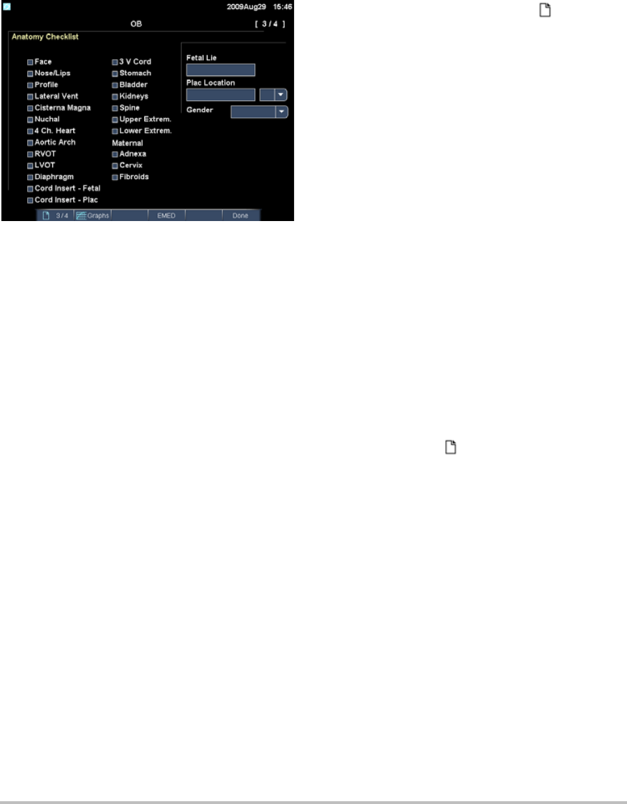
70 Patient report
Figure 3 OB Anatomy Checklist Page
To fill out the OB anatomy checklist
Youcandocumentreviewedanatomy.
OntheAnatomy ChecklistpageintheOB
patientreport,selectthecheckboxes.
PresstheTABkeytomovebetweenfieldsand
theSPACEBARtoselectanddeselectitemsin
thechecklist.
To complete the OB biophysical profile
Onpage2oftheOBpatientreport,select
valuesunderBPP.
Thetotaliscalculatedwhenvaluesare
selected.NST(non‐stresstest)isoptional.
To display OB graphs
YoucandisplayOBgraphsiftheLMPorEstab.
DDfieldsarecompleteinthepatientinformation
form.
1OntheOBpatientreport,selectGraphs
on‐screen.
2IntheGraphslist,selectthedesired
measurement/author.
Thegraphfortheselectedmeasurement
appears.Youcanselectanother
measurement/authororselect 1/x
on‐screen.
Fortwins,bothmeasurementsetsareplotted
onthesamegraph.
3(Optional)PresstheSAVEkeytosavethe
currentgraphpage.
4Selectoneofthefollowingon‐screen:
•Reporttoreturntothepreviouspatient
reportpage
•Donetoreturntoliveimaging.
EMED worksheets
EMEDworksheetscontainresultsfromEMED
calculationsandcheckliststhatyoucancomplete.
To display an EMED worksheet
Thisfeatureisoptional.
1Afterorduringtheexam,presstheREPORT
key.
2SelectEMEDon‐screen.
3SelecttheworksheetfromtheWorksheetlist
orbyselectingx/xon‐screen.

Chapter 5: Troubleshooting and Maintenance 71
Troubleshooting
Chapter 5: Troubleshooting and Maintenance
Thischaptercontainsinformationtohelpcorrect
problemswithsystemoperation,toentera
softwarelicense,andtotakepropercareofthe
system,transducer,andaccessories.
Troubleshooting
Ifyouencounterdifficultywiththesystem,use
thefollowinglisttohelptroubleshootthe
problem.Iftheproblempersists,contactSonoSite
TechnicalSupport.(See“SonoSiteTechnical
Support”onpage vii.)
System does not turn on.Checkallpower
connections.
RemovetheDCinputconnectorandbattery,wait
10seconds,andthenreinstallthem.
Ensurethatthebatteryischarged.
System image quality is poor.Adjustthedisplay
toimproveviewingangle.
Adjustthebrightness.
Adjustthegain.
No CPD image.Adjustthegain.
No Color image.AdjustthegainorthePRFscale.
NoOBmeasurementselections.
SelecttheOBexamtype.
Print does not work.Selecttheprinteronthe
Connectivitysetuppage.See“Toconfigurethe
systemforaprinter”onpage 19.
Checktheprinterconnections.
Ensurethattheprinteristurnedonandsetup
properly.Seetheprintermanufacturer’s
instructions,ifnecessary.
DVD recorder does not record.ChecktheDVD
recorderconnections.
EnsurethattheDVDrecorderisturnedonand
setupproperly.SeetheapplicableSonoSite
accessoryuserguideandthemanufacturers’
instructions.
Externalmonitordoesnotwork.
Checkthemonitorconnections.
Checkthemonitortoensurethatitisturnedon
andsetupproperly.Seethemonitor
manufacturers’instructions,ifnecessary.
System does not recognize the transducer.
Disconnectandreconnectthetransducer.
A maintenance icon appears on the system
screen.Systemmaintenancemayberequired.
RecordthenumberinparenthesesontheC:line
andcontactSonoSiteoryourSonoSite
representative.
Software licensing
SonoSitesoftwareiscontrolledbyalicensekey.
Afteryouinstallnewsoftware,thesystem
promptsyouforalicensekey.Youmustobtain
onekeyforeachsystemortransducerthatuses
thesoftware.
Thesoftwarewilloperateforashorttime(the
graceperiod)withoutalicensekey.Duringthe
graceperiod,allsystemfunctionsareavailable.
Afterthegraceperiod,thesystemisnotusable
untilyouenteravalidlicensekey.Graceperiod
timeisnotusedwhilethesystemisofforasleep.
Graceperiodtimeremainingappearsonthe
licenseupdatescreen.
Caution: After the grace period expires, all
system functions except licensing
are unavailable until a valid license
key is entered.

72 Maintenance
Toobtainalicensekeyforyoursoftware,contact
SonoSiteTechnicalSupport.(See“SonoSite
TechnicalSupport”onpage vii.)Youneedto
providethefollowinginformation.(See“System
Informationsetup”onpage 23.)
Afteryouobtainalicensekey,youmustenterit
intothesystem.
To enter a license key
1Turnonthesystem.
Thelicenseupdatescreenappears.
2EnterthelicensekeyintheEnter license
numberfield.
3SelectDoneon‐screen.
Ifyouenteredavalidlicensekeybutthe
licenseupdatescreenappears,verifythatyou
enteredthelicensekeycorrectly.Ifthelicense
updatescreenstillappears,contactSonoSite
TechnicalSupport.(See“SonoSiteTechnical
Support”onpage vii.)
Maintenance
Usetherecommendationsinthissectionwhen
cleaningordisinfectingyourultrasoundsystem,
transducer,andaccessories.Usethecleaning
recommendationsintheperipheral
manufacturer’sinstructionswhencleaningor
disinfectingyourperipherals.
Noperiodicorpreventivemaintenanceis
requiredforthesystem,transducer,or
accessoriesotherthancleaninganddisinfecting
thetransduceraftereveryuse.(See“Cleaning
anddisinfectingtransducers”onpage 74.)There
arenointernalcomponentsthatrequireperiodic
testingorcalibration.Allmaintenance
requirementsaredescribedinthischapterandin
theultrasoundsystemservicemanual.
Performingmaintenanceproceduresnot
describedintheuserguideorservicemanual
mayvoidtheproductwarranty.
ContactSonoSiteTechnicalSupportforany
maintenancequestions.(See“SonoSiteTechnical
Support”onpage vii.)
System Software Transducer Software
Name of person
installing the
upgrade
Name of person installing
the upgrade
Serial number (on
bottom of system)
Transducer serial number
ARM version Transducer part number
(REF)
or model number (for
example, C60x)
PCBA serial
number
Transducer bundle version
WARNING: Disinfectants and cleaning methods
listed are recommended by
SonoSite for compatibility with
product materials, not for biological
effectiveness. Refer to the
disinfectant label instructions for
guidance on disinfection efficacy
and appropriate clinical uses.
The level of disinfection required for
a device is dictated by the type of
tissue it contacts during use. To
avoid infection, ensure that the
disinfectant type and the solution
strength and duration are
appropriate for the equipment. For
information, see the disinfectant
label instructions and the
recommendations of the
Association for Professionals in
Infection Control and Epidemiology
(APIC) and the FDA.

Chapter 5: Troubleshooting and Maintenance 73
Troubleshooting
Cleaning and disinfecting the
ultrasound system
Theexteriorsurfaceoftheultrasoundsystemand
theaccessoriescanbecleanedanddisinfected
usingarecommendedcleanerordisinfectant.See
“Recommendeddisinfectants”onpage 77. To clean the LCD screen
Dampenaclean,non‐abrasive,cottoncloth
withanethanolic‐basedcleaner,andwipethe
screenclean.
Applythecleanertotheclothratherthanthe
surfaceofthescreen.
To clean and disinfect system surfaces
1Turnoffthesystem.
2Disconnectthesystemfromthepowersupply,
orremoveitfromthemini‐dockordocking
system.
3Cleantheexteriorsurfacesusingasoftcloth
lightlydampenedinamildsoapordetergent
cleaningsolutiontoremoveanyparticulate
matterorbodyfluids.
Applythesolutiontotheclothratherthanthe
surface.
4Mixthedisinfectantsolutioncompatiblewith
thesystem,followingdisinfectantlabel
WARNING: To prevent contamination, the use
of sterile transducer sheaths and
sterile coupling gel is
recommended for clinical
applications of an invasive or
surgical nature. Do not apply the
transducer sheath and gel until you
are ready to perform the procedure.
Caution: Some transducer sheaths contain
natural rubber latex and talc, which
can cause allergic reactions in some
individuals. Refer to 21 CFR 801.437,
User labeling for devices that
contain natural rubber.
WARNING: To avoid electrical shock, before
cleaning, disconnect the system
from the power supply or remove
from the mini-dock or docking
system.
To avoid infection always use
protective eyewear and gloves
when performing cleaning and
disinfecting procedures.
To avoid infection, ensure that the
solution expiration date has not
passed.
Caution: Do not spray cleaners or
disinfectant directly on the system
surfaces. Doing so may cause
solution to leak into the system,
damaging the system and voiding
the warranty.
Do not use strong solvents such as
thinner or benzene, or abrasive
cleansers, since these will damage
the exterior surfaces.
Use only recommended cleaners or
disinfectants on system surfaces.
Immersion-type disinfectants are
not approved for use on system
surfaces.
When you clean the system, ensure
that the solution does not get
inside the system controls or the
battery compartment.
Do not scratch the LCD screen.

74 Maintenance
instructionsforsolutionstrengthsand
disinfectantcontactduration.
5Wipesurfaceswiththedisinfectantsolution.
6Airdryortoweldrywithacleancloth.
Cleaning and disinfecting transducers
Todisinfectthetransduceranditscable,usethe
immersionmethodorthewipemethod.
Immersibletransducerscanbedisinfectedonlyif
theproductlabelingindicatestheycanbeused
withanimmersionmethod.
SeeTable 1,“DisinfectantCompatibilitywith
SystemandTransducers”onpage 77.
To clean and disinfect a transducer (wipe
method)
1Disconnectthetransducerfromthesystem.
2Removeanytransducersheath.
3Cleanthesurfaceusingasoftclothlightly
dampenedinamildsoapordetergent
cleaningsolutiontoremoveanyparticulate
matterorbodyfluids.
Applythesolutiontotheclothratherthanthe
surface.
4Rinsewithwaterorwipewith
water‐dampenedcloth;thenwipewithadry
cloth.
5Mixthedisinfectantsolutioncompatiblewith
thetransducer,followingdisinfectantlabel
instructionsforsolutionstrengthsand
disinfectantcontactduration.
6Wipesurfaceswiththedisinfectantsolution.
WARNING: To avoid electrical shock, before
cleaning, disconnect the transducer
from the system.
To avoid injury, always use
protective eyewear and gloves
when performing cleaning and
disinfecting procedures.
To avoid infection, ensure that the
solution expiration date has not
passed.
Caution: Transducers must be cleaned after
every use. Cleaning transducers is
necessary prior to effective
disinfection. Ensure that you follow
the manufacturer's instructions
when using disinfectants.
Do not use a surgeon's brush when
cleaning transducers. Even the use
of soft brushes can damage a
transducer. Use a soft cloth.
Using a non-recommended
cleaning or disinfection solution,
incorrect solution strength, or
immersing a transducer deeper or
for a longer period of time than
recommended can damage or
discolor the transducer and void the
transducer warranty.
Do not allow cleaning solution or
disinfectant into the transducer
connector.
Do not allow disinfectant to contact
metal surfaces. Use a soft cloth
lightly dampened in a mild soap or
compatible cleaning solution to
remove any disinfectant that
remains on metal surfaces.
Attempting to disinfect a
transducer or transducer cable
using a method other than the one
included here can damage the
transducer and void the warranty.

Chapter 5: Troubleshooting and Maintenance 75
Troubleshooting
7Airdry.
8Examinethetransducerandcablefordamage
suchascracks,splitting,orfluidleaks.
Ifdamageisevident,discontinueuseofthe
transducer,andcontactSonoSiteoryourlocal
representative.
To clean and disinfect a transducer
(immersion method)
1Disconnectthetransducerfromthesystem.
2Removeanytransducersheath.
3Cleanthesurfaceusingasoftclothlightly
dampenedinamildsoaporcompatible
cleaningsolutiontoremoveanyparticulate
matterorbodyfluids.
Applythesolutiontotheclothratherthanthe
surface.
4Rinsewithwaterorwipewith
water‐dampenedcloth,andthenwipewitha
drycloth.
5Mixthedisinfectantsolutioncompatiblewith
thetransducer,followingdisinfectantlabel
instructionsforsolutionstrengthsand
disinfectantcontactduration.
6Immersethetransducerintothedisinfection
solutionnotmorethan12‐18 inches
(31‐46 cm)fromthepointwherethecable
enterstheconnector.
Followtheinstructionsonthedisinfectant
labelforthedurationofthetransducer
immersion.
7Usingtheinstructionsonthedisinfectant
label,rinsetothepointoftheprevious
immersion,andthenairdryortoweldrywith
acleancloth.
8Examinethetransducerandcablefordamage
suchascracks,splitting,orfluidleaks.
Ifdamageisevident,discontinueuseofthe
transducer,andcontactSonoSiteoryourlocal
representative.
Cleaning and disinfecting the battery
To clean and disinfect a battery (wipe
method)
1Removethebatteryfromthesystem.
2Cleanthesurfaceusingasoftclothlightly
dampenedinamildsoapordetergent
cleaningsolution.
Applythesolutiontotheclothratherthanthe
surface.
3Wipethesurfaceswiththedisinfection
solution.Sani‐ClothHB,Sani‐ClothWipes,or
70%isopropylalcoholisrecommended.
4Airdr.
Cleaning the footswitch
To clean the footswitch
1Dampenanon‐abrasiveclothwithoneofthe
followingproducts:
•Isopropylalcohol
•Soapandwater
•Cidex
•SodiumHypochlorite5.25%(Bleach)
diluted10:1
2Wringoutclothuntilslightlywetandthen
gentlyrubsoiledareauntilclean.
Caution: To avoid damaging the battery, do
not allow cleaning solution or
disinfectant to come in contact
with the battery terminals.
Caution: To avoid damaging the footswitch,
do not sterilize. It is not intended for
use in a sterile environment.

76 Maintenance
Cleaning and disinfecting ECG cables
To clean and disinfect the ECG cable (wipe
method)
1Removethecablefromthesystem.
2Cleanthesurfaceusingasoftclothlightly
dampenedinamildsoapordetergent
cleaningsolution.
Applythesolutiontotheclothratherthanthe
surface.
3Wipethesurfaceswithanyofthefollowing
products:
• Bleach(sodiumhypochlorite)
•Cidexdisinfectants
•Greensoap
4Airdryortoweldrywithacleancloth.
Caution: To avoid damaging the ECG cable,
do not sterilize.

Chapter 5: Troubleshooting and Maintenance 77
Troubleshooting
Recommended disinfectants
Seewww.sonosite.comforupdatedcleaninganddisinfectantinformation.
Table 1 does not have the following regulatory information for disinfectants:
•EPA Registration
• FDA 510(k) clearance (liquid sterilant, high level disinfectant)
• CE approval
Before using a disinfectant, confirm that its regulatory status is appropriate for your jurisdiction and use. Verify
expiration dates on chemicals.
When disposing of chemicals, follow manufacturer recommendations and EPA regulations.
Table 1: Disinfectant Compatibility with System and Transducers
Disinfection and
Cleaning Solutions
Country
of Origin Type Active Ingredient
C60x
ICTx
L38x
P10x
P21x
SLAx
D2x HFL38x C11x/
L25x
System
Surfaces
AbcoCide 14 USA Liquid Gluteraldehyde AAAU
Accel Plus CAN Wipe Hydrogen Peroxide NNNU
Accel TB CAN Wipe Hydrogen Peroxide NNNU
Accel Wipes CAN Wipe Hydrogen Peroxide AAAU
Aidal Plus AUS Liquid Gluteraldehyde AAAU
Alkacide FRA Liquid Gluteraldehyde AAAU
Alkazyme FRA Liquid Quat. Ammonia AAAU
Anioxyde 1000 FRA Liquid Peracetic Acid NNNU
Aquatabs (1000) IRL Tablet Sodium
Dichloroisocyanurate
ANAU

78
Aquatabs (2000) IRL Tablet Sodium
Dichloroisocyanurate
AUNAU
Aquatabs (5000) IRL Tablet Sodium
Dichloroisocyanurate
NUNNU
Ascend USA Liquid Quat Ammonia AUAAU
Asepti-HB USA Liquid Quat Ammonia AUAAU
Asepti-Steryl USA Spray Ethanol AUAAU
Asepti-Wipes USA Wipe Propanol (Isopropyl
Alcohol
AUAAA
Bacillocid rasant DEU Liquid Glut./Quat. Ammonia AUAAU
Bacoban DEU Liquid Ethanol Isopropanol AAUUU
Bacoban WB DEU Liquid Benzalkoniumchloride
Diethylenglycol
AAUUU
Banicide USA Liquid Gluteraldehyde AUUAU
Betadine USA Liquid Providone-Iodine NUNAU
Bleach USA Liquid NaCl Hypochlorite AUAAU
Cavicide USA Liquid Isopropyl AUAAU
Caviwipes USA Wipes Isopropanol AUANA
Chlor-Clean GBR Liquid Sodium
Dichloroisocyanurate
AUNAU
Table 1: Disinfectant Compatibility with System and Transducers (continued)
Disinfection and
Cleaning Solutions
Country
of Origin Type Active Ingredient
C60x
ICTx
L38x
P10x
P21x
SLAx
D2x HFL38x C11x/
L25x
System
Surfaces

Chapter 5: Troubleshooting and Maintenance 79
Troubleshooting
Cidalkan FRA Liquid Alkylamine, isopropanol UNUUU
Cidalkan Lingettes FRA Wipes Ethyl Alcohol UNUUU
Cidex USA Liquid Gluteraldehyde AUAAA
Cidex OPA USA Liquid Ortho-phthaldehyde AAAAU
Cidex Plus USA Liquid Gluteraldehyde AUAAA
Cleanisept DEU Wipes Quat. Ammonia AAAAA
Clorox Wipes USA Wipes Isopropanol AUAAU
Control III USA Liquid Quat. Ammonia AUANU
Coverage Spray USA Spray Quat. Ammonia AUANN
Denatured Alcohol USA Liquid Ethanol NUNNU
DentaSept FRA Liquid Quat. Ammonia NUNNU
DisCide Ultra
Disinfecting
Towelettes
USA Wipes Isopropyl Alcohol UUUUN
DisCide Wipes USA Wipes Isopropyl Alcohol AUAAN
DisOPA JPN Liquid Ortho-phthaldehyde AAAAA
Dispatch USA Spray NaCl Hypochlorite AAAAU
Dynacide PA FRA Liquid Peracetic Acid UAUUU
Table 1: Disinfectant Compatibility with System and Transducers (continued)
Disinfection and
Cleaning Solutions
Country
of Origin Type Active Ingredient
C60x
ICTx
L38x
P10x
P21x
SLAx
D2x HFL38x C11x/
L25x
System
Surfaces

80
End-Bac II USA Liquid Quat. Ammonia AUAAA
Endozime AW Plus FRA Liquid Propanol AUAAU
Envirocide USA Liquid Isopropyl AUUNU
Enzol USA Cleaner Ethylene Glycol AUAAU
Expose USA Liquid Isopropyl AUAAU
Gigasept AF DEU Liquid Quat. Ammonia AUAAU
Gigasept FF DEU Liquid Bersteinsaure NUNNU
Gluteraldehyde SDS USA Liquid Gluteraldehyde AUUAU
Hexanios FRA Liquid Polyhexanide/Quat.
Ammonia
AUAAU
Hi Tor Plus USA Liquid Chloride AUANU
Hibiclens USA Cleaner Chlorhexidine AUAAU
Hydrogen Peroxide USA Liquid Hydrogen Peroxide AAAAA
Isopropanol Alcohol ALL Liquid Alcohol NUNNU
Kodan Tücher DEU Liquid Propanol AUAAN
Kohrsolin ff DEU Liquid Gluteraldehyde AUUAU
Korsolex basic DEU Liquid Gluteraldehyde NUNNU
Lem-O-Quat USA Liquid Alkyl/Chloride UAUUU
Table 1: Disinfectant Compatibility with System and Transducers (continued)
Disinfection and
Cleaning Solutions
Country
of Origin Type Active Ingredient
C60x
ICTx
L38x
P10x
P21x
SLAx
D2x HFL38x C11x/
L25x
System
Surfaces

Chapter 5: Troubleshooting and Maintenance 81
Troubleshooting
LpHse USA Liquid O-phenylphenol AUAAU
Lysol USA Spray Ethanol NUNNU
Lysol IC USA Liquid O-phenylphenol AUNAU
Madacide 1 USA Liquid Isopropanol ANANN
Matar USA Liquid O-phenylphenol AUUAU
MetriCide 14 USA Liquid Gluteraldehyde AUAAU
MetriCide 28 USA Liquid Gluteraldehyde AUAAU
MetriZyme USA Cleaner Propylene Glycol AUAAU
Mikrobak forte DEU Liquid Ammonium Chloride AUAAU
Mikrozid Wipes DEU Wipe Ethanol/Propanol AUAAN
Nuclean FRA Spray Alcohol/Biguanide AUAAU
Precise USA Spray O-phenylphenol NUNNU
Ruthless USA Spray Quat. Ammonia AUANU
Sagrosept Wipe DEU Wipe Propanol AUAAU
Salvanios pH 7 FRA Liquid Quat. Ammonia AUAAU
Sani-Cloth HB USA Wipe Quat. Ammonia AUANA
Sani-Cloth Plus USA Wipe Quat. Ammonia AUAAA
Sekusept DEU Liquid Gluteraldehyde UAUUU
Table 1: Disinfectant Compatibility with System and Transducers (continued)
Disinfection and
Cleaning Solutions
Country
of Origin Type Active Ingredient
C60x
ICTx
L38x
P10x
P21x
SLAx
D2x HFL38x C11x/
L25x
System
Surfaces

82
Sklar USA Liquid Isopropanol AUANU
Sporicidin USA Liquid Phenol ANAAU
Sporicidin Wipes USA Wipe Phenol AUAAN
Staphene USA Spray Ethanol AUNAN
Steranios FRA Liquid Gluteraldehyde AUAAU
Super Sani-Cloth USA Wipe Isopropyl Alcohol NUNNN
T-Spray USA Spray Quat. Ammonia AUANN
T-Spray II USA Spray Alkyl/Chloride AUAAU
TASK 105 USA Spray Quat. Ammonia AUAAU
TBQ USA Liquid Alkyl AUAAU
Theracide Plus
Wipes
USA Wipe Quat. Ammonia AUAAA
Tor USA Liquid Quat. Ammonia AUANU
Transeptic USA Cleaner Alcohol NUNNU
Tristel GBR Liquid Chlorine Dioxide AAAAU
Tristel Duo GBR UUUUU
Tristel Solo GBR Foam Hexamethylenebiguanide UAUUU
Tristel Wipes GBR Wipe Chlorine Dioxide NANNA
Table 1: Disinfectant Compatibility with System and Transducers (continued)
Disinfection and
Cleaning Solutions
Country
of Origin Type Active Ingredient
C60x
ICTx
L38x
P10x
P21x
SLAx
D2x HFL38x C11x/
L25x
System
Surfaces

Chapter 5: Troubleshooting and Maintenance 83
Troubleshooting
Vesphene II USA Liquid Sodium/
o-Phenylphenate
AUAAU
Virex II 256 USA Liquid Ammonium Chloride AUAAU
Virex TB USA Liquid Quat. Ammonia AUANN
Virox 5 CAN Wipe Hydrogen Peroxide AAAAA
Virufen FRA Liquid Alkyl Ammonium Chloride UAUUU
Wavicide -01 USA Liquid Gluteraldehyde NUNNU
Wavicide -06 USA Liquid Gluteraldehyde AUAAU
Wet Wipe
Disinfection
DNK Wipe Guanidinium-chloride UAUUU
Wex-Cide USA Liquid O-phenylphenol AUAAU
A = Acceptable
N = No (Do not use)
U = Untested (Do not use)
Table 1: Disinfectant Compatibility with System and Transducers (continued)
Disinfection and
Cleaning Solutions
Country
of Origin Type Active Ingredient
C60x
ICTx
L38x
P10x
P21x
SLAx
D2x HFL38x C11x/
L25x
System
Surfaces

84

Chapter 6: Safety 85
Safety
Chapter 6: Safety
Thischaptercontainsinformationrequiredbyregulatoryagencies,includinginformation
abouttheALARA(aslowasreasonablyachievable)principle,theoutputdisplaystandard,
acousticpowerandintensitytables,andothersafetyinformation.Theinformationappliesto
theultrasoundsystem,transducer,accessories,andperipherals.
Ergonomic safety
Thesehealthyscanningguidelinesareintendedtoassistyouinthecomfortandeffectiveuse
ofyourultrasoundsystem.
WARNING: To prevent musculoskeletal disorders, follow the guidelines in this section.
Use of an ultrasound system may be linked to musculoskeletal disorders (MSDs)a,b,c.
Use of an ultrasound system is defined as the physical interaction between the
operator, the ultrasound system, and the transducer.
When using an ultrasound system, as with many similar physical activities, you may
experience occasional discomfort in your hands, fingers, arms, shoulders, eyes, back,
or other parts of your body. However, if you experience symptoms such as constant
or recurring discomfort, pain, throbbing, aching, tingling, numbness, burning
sensation, or stiffness, do not ignore these warning signs. Promptly see a qualified
health professional. Symptoms such as these can be linked with MSDs. MSDs can be
painful and may result in potentially disabling injuries to the nerves, muscles,
tendons, or other parts of the body. Examples of MSDs include carpal tunnel
syndrome and tendonitis.
While researchers are not able to definitively answer many questions about MSDs,
there is a general agreement that certain factors are associated with their
occurrence including preexisting medical and physical conditions, overall health,
equipment and body position while doing work, frequency of work, duration of
work, and other physical activities that may facilitate the onset of MSDsd. This
chapter provides guidelines that may help you work more comfortably and may
reduce your risk of MSDse,f.
a.Magnavita, N., L. Bevilacqua, P. Mirk, A. Fileni, and N. Castellino. “Work-related Musculoskeletal Complaints
in Sonologists.” Occupational Environmental Medicine. 41:11 (1999), 981-988.
b.Craig, M. “Sonography: An Occupational Hazard?” Journal of Diagnostic Medical Sonography. 3 (1985),
121-125.
c.Smith, C.S., G.W. Wolf, G. Y. Xie, and M. D. Smith. “Musculoskeletal Pain in Cardiac Ultrasonographers:
Results of a Random Survey.” Journal of American Society of Echocardiography. (May1997), 357-362.
d.Wihlidal, L.M. and S. Kumar. “An Injury Profile of Practicing Diagnostic Medical Sonographers in Alberta.”
International Journal of Industrial Ergonomics. 19 (1997), 205-216.

86
Position the system
Promote comfortable shoulder, arm, and hand postures
•Useastandtosupporttheweightoftheultrasoundsystem.
Minimize eye and neck strain
•Ifpossible,positionthesystemwithinreach.
•Adjusttheangleofthesystemanddisplaytominimizeglare.
•Ifusingastand,adjustitsheightsothatthedisplayisatorslightlybeloweyelevel.
Position yourself
Support your back during an exam
•Useachairthatsupportsyourlowerback,thatadjuststoyourworksurfaceheight,that
promotesanaturalbodyposture,andthatallowsquickheightadjustments.
•Alwayssitorstandupright.Avoidbendingorstooping.
Minimize reaching and twisting
•Useabedthatisheightadjustable.
•Positionthepatientasclosetoyouaspossible.
•Faceforward.Avoidtwistingyourheadorbody.
•Moveyourentirebodyfronttoback,andpositionyourscanningarmnexttoorslightlyin
frontofyou.
•Standfordifficultexamstominimizereaching.
•Positiontheultrasoundsystemordisplaydirectlyinfrontofyou.
•Provideanauxiliarymonitorforpatientviewing.
Promote comfortable shoulder and arm postures
•Keepyourelbowclosetoyourside.
•Relaxyourshouldersinalevelposition.
• Supportyourarmusingasupportcushionorpillow,orrestitonthebed.
e.Habes, D.J. and S. Baron. “Health Hazard Report 99-0093-2749.” University of Medicine and Dentistry of New
Jersey. (1999).
f.Vanderpool, H.E., E.A. Friis, B.S. Smith, and K.L. Harms. “Prevalence of Carpal Tunnel Syndrome and Other
Work-related Musculoskeletal Problems in Cardiac Sonographers.” Journal of Medicine. 35:6 (1993), 605-610.

Chapter 6: Safety 87
Safety
Promote comfortable hand, wrist, and finger postures
•Holdthetransducerlightlyinyourfingers.
• Minimizethepressureappliedonthepatient.
•Keepyourwristinastraightposition.
Take breaks, exercise, and vary activities
• Minimizingscanningtimeandtakingbreakscaneffectivelyallowyourbodytorecoverfrom
physicalactivityandhelpyouavoidMSDs.Someultrasoundtasksmayrequirelongeror
morefrequentbreaks.However,simplychangingtaskscanhelpsomemusclegroupsrelax
whileothersremainorbecomeactive.
•Workefficientlybyusingthesoftwareandhardwarefeaturescorrectly.
•Keepmoving.Avoidsustainingthesameposturebyvaryingyourhead,neck,body,arm,
andlegpositions.
•Dotargetedexercises.Targetedexercisescanstrengthenmusclegroups,whichmayhelpyou
avoidMSDs.Contactaqualifiedhealthprofessionaltodeterminestretchesandexercises
thatarerightforyou.
Electrical safety classification
Class I equipment Ultrasound system powered from power supply or part
of the Mobile Docking System
Internally powered equipment Ultrasound system not connected to the power supply
(battery only)
Type BF applied parts Ultrasound transducers
Type CF applied parts ECG module/ECG leads
IPX-7 (watertight equipment) Ultrasound transducers
IPX-8 (watertight equipment) Footswitch
Non AP/APG Ultrasound system power supply, docking system, and
peripherals. Equipment is not suitable for use in the
presence of flammable anaesthetics.

88
Electrical safety
ThissystemmeetsEN60601‐1,ClassI/internally‐poweredequipmentrequirementsandType
BFisolatedpatient‐appliedpartssafetyrequirements.
Thissystemcomplieswiththeapplicablemedicalequipmentrequirementspublishedinthe
CanadianStandardsAssociation(CSA),EuropeanNormHarmonizedStandards,and
UnderwritersLaboratories(UL)safetystandards.SeeChapter 8,“Specifications.”
Formaximumsafetyobservethefollowingwarningsandcautions.
WARNING: To avoid discomfort or minor risk of patient injury, keep hot surfaces away from the
patient.
Under certain circumstances, the transducer connector and back of the display
enclosure can reach temperatures that exceed EN60601-1 limits for patient contact,
therefore only the operator shall handle the system. This does not include the
transducer face.
To avoid discomfort or minor risk of operator injury when handling the transducer
connector, the system should not be operated for more than 60 minutes
continuously in a live-scan mode (as opposed to freeze or sleep modes).
To avoid the risk of electrical shock or injury, do not open the system enclosures. All
internal adjustments and replacements, except battery replacement, must be made
by a qualified technician.
To avoid the risk of injury, do not operate the system in the presence of flammable
gasses or anesthetics. Explosion can result.
To avoid the risk of electrical shock, use only properly grounded equipment. Shock
hazards exist if the power supply is not properly grounded. Grounding reliability can
only be achieved when equipment is connected to a receptacle marked “Hospital
Only” or “Hospital Grade” or the equivalent. The grounding wire must not be
removed or defeated.
To avoid the risk of electrical shock, when using the system in an environment where
the integrity of the protective earth conductor arrangement is in doubt, operate the
system on battery power only without using the power supply.
To avoid the risk of electrical shock, do not connect the system’s power supply or a
docking system to an MPSO or extension cord.
To avoid the risk of electrical shock, before using the transducer, inspect the
transducer face, housing, and cable. Do not use the transducer if the transducer or
cable is damaged.
To avoid the risk of electrical shock, always disconnect the power supply from the
system before cleaning the system.

Chapter 6: Safety 89
Safety
WARNING: To avoid the risk of electrical shock, do not use any transducer that has been
immersed beyond the specified cleaning or disinfection level. See Chapter 5,
“Troubleshooting and Maintenance.”
To avoid the risk of electrical shock to the patient, do not simultaneously touch the
patient and the ungrounded signal input/output connectors on the back of the
ultrasound system.
To avoid the risk of electrical shock and fire hazard, inspect the power supply, AC
power cords, cables, and plugs on a regular basis. Ensure that they are not damaged.
To avoid the risk of electrical shock and fire hazard, the power cord set that connects
the power supply of the ultrasound system or MDS to mains power must only be
used with the power supply or docking system, and cannot be used to connect
other devices to mains power.
To avoid the risk of electrical shock, use only accessories and peripherals
recommended by SonoSite, including the power supply. Connection of accessories
and peripherals not recommended by SonoSite could result in electrical shock.
Contact SonoSite or your local representative for a list of accessories and peripherals
available from or recommend by SonoSite.
To avoid the risk of electrical shock, use commercial grade peripherals
recommended by SonoSite on battery power only. Do not connect these products
to AC mains power when using the system to scan or diagnose a patient/subject.
Contact SonoSite or your local representative for a list of the commercial grade
peripherals available from or recommended by SonoSite.
To avoid the risk of electrical shock to the patient/subject, do not touch the system
battery contacts while simultaneously touching a patient/subject.
To prevent injury to the operator/bystander, the transducer must be removed from
patient contact before the application of a high-voltage defibrillation pulse.
To avoid possible electrical shock or electromagnetic interference, verify proper
operation and compliance with relevant safety standards for all equipment before
clinical use. Connecting additional equipment to the ultrasound system constitutes
configuring a medical system. SonoSite recommends verifying that the system, all
combinations of equipment, and accessories connected to the ultrasound system
comply with JACHO installation requirements and/or safety standards such as
AAMI-ES1, NFPA 99 OR IEC Standard 60601-1-1 and electromagnetic compatibility
standard IEC 60601-1-2 (Electromagnetic compatibility), and are certified according
to IEC Standard 60950 (Information Technology Equipment (ITE)).
Caution: Do not use the system if an error message appears on the image display: note the
error code; call SonoSite or your local representative; turn off the system by pressing
and holding the power key until the system powers down.
To avoid increasing the system and transducer connector temperature, do not block
the airflow to the ventilation holes on the side of the system.

90
Equipment safety
Toprotectyourultrasoundsystem,transducer,andaccessories,followtheseprecautions.
Battery safety
Topreventthebatteryfrombursting,igniting,oremittingfumesandcausingpersonalinjury
orequipmentdamage,observethefollowingprecautions.
Caution: Excessive bending or twisting of cables can cause a failure or intermittent operation.
Improper cleaning or disinfecting of any part of the system can cause permanent
damage. For cleaning and disinfecting instructions, see Chapter 5, “Troubleshooting
and Maintenance.”
Do not submerge the transducer connector in solution. The cable is not liquid-tight
beyond the transducer connector/cable interface.
Do not use solvents such as thinner or benzene, or abrasive cleaners on any part of
the system.
Remove the battery from the system if the system is not likely to be used for some
time.
Do not spill liquid on the system.
WARNING: The battery has a safety device. Do not disassemble or alter the battery.
Charge the batteries only when the ambient temperature is between 0° and 40°C
(32° and 104°F).
Do not short-circuit the battery by directly connecting the positive and negative
terminals with metal objects.
Do not touch battery contacts.
Do not heat the battery or discard it in a fire.
Do not expose the battery to temperatures over 60°C (140°F). Keep it away from fire
and other heat sources.
Do not charge the battery near a heat source, such as a fire or heater.
Do not leave the battery in direct sunlight.
Do not pierce the battery with a sharp object, hit it, or step on it.
Do not use a damaged battery.
Do not solder a battery.
The polarity of the battery terminals are fixed and cannot be switched or reversed.
Do not force the battery into the system.

Chapter 6: Safety 91
Safety
Do not connect the battery to an electrical power outlet.
WARNING: Do not continue recharging the battery if it does not recharge after two successive
six hour charging cycles.
If the battery leaks or emits an odor, remove it from all possible flammable sources.
Caution: To avoid the battery bursting, igniting, or emitting fumes from the battery and
causing equipment damage, observe the following precautions:
Do not immerse the battery in water or allow it to get wet.
Do not put the battery into a microwave oven or pressurized container.
If the battery emits an odor or heat, is deformed or discolored, or in any way appears
abnormal during use, recharging or storage, immediately remove it and stop using
it. If you have any questions about the battery, consult SonoSite or your local
representative.
Store the battery between -20°C (-4°F) and 60°C (140°F).
Use only SonoSite batteries.
Do not use or charge the battery with non-SonoSite equipment. Only charge the
battery with the system.

92
Clinical safety
WARNING: Non-medical (commercial) grade peripheral monitors have not been verified or
validated by SonoSite as being suitable for diagnosis.
To avoid the risk of a burn hazard, do not use the transducer with high frequency
surgical equipment. Such a hazard may occur in the event of a defect in the high
frequency surgical neutral electrode connection.
Do not use the system if it exhibits erratic or inconsistent behavior. Discontinuities in
the scanning sequence are indicative of a hardware failure that must be corrected
before use.
Some transducer sheaths contain natural rubber latex and talc, which can cause
allergic reactions in some individuals. Refer to 21 CFR 801.437, User labeling for
devices that contain natural rubber.
Perform ultrasound procedures prudently. Use the ALARA (as low as reasonably
achievable) principle and follow the prudent use information concerning MI and TI.
SonoSite does not currently recommend a specific brand of acoustic standoff. If an
acoustic standoff is used, it must have a minimum attentuation of .3dB/cm/MHz.
Some SonoSite transducers are approved for intraoperative applications if a
market-cleared sheath is used.
To avoid injury or reduce the risk of infection to the patient, observe the following:
• • Follow Universal Precautions when inserting and maintaining a medical device
for interventional and intraoperative procedures.
• Appropriate training in interventional and intraoperative procedures as dictated
by current relevant medical practices as well as in proper operation of the
ultrasound system and transducer is required. During vascular access, the
potential exists for serious complications including without limitation the
following: pneumothorax, arterial puncture, guidewire misplacement, and risks
normally associated with local or general anesthesia, surgery, and post-operative
recovery.
To avoid device damage or patient injury, do not use the P10x, P17x, or P21x needle
guide bracket on patients with pacemakers or medical electronic implants. The
needle guide bracket for the P10x, P17x, and P21x transducers contains a magnet
that is used to ensure the bracket is correctly oriented on the transducer. The
magnetic field in direct proximity to the pacemaker or medical electronic implant
may have an adverse effect.

Chapter 6: Safety 93
Safety
Hazardous materials
Electromagnetic compatibility
Theultrasoundsystemhasbeentestedandfoundtocomplywiththeelectromagnetic
compatibility(EMC)limitsformedicaldevicestoIEC60601‐1‐2:2001.Theselimitsaredesigned
toprovidereasonableprotectionagainstharmfulinterferenceinatypicalmedicalinstallation.
WARNING: The liquid crystal display (LCD) contains mercury. Dispose of the LCD properly in
accordance with local regulations.
Caution: Medical electrical equipment requires special precautions regarding EMC and must
be installed and operated according to these instructions. It is possible that high
levels of radiated or conducted radio-frequency electromagnetic interference (EMI)
from portable and mobile RF communications equipment or other strong or nearby
radio-frequency sources, could result in performance disruption of the ultrasound
system. Evidence of disruption may include image degradation or distortion, erratic
readings, equipment ceasing to operate, or other incorrect functioning. If this occurs,
survey the site to determine the source of disruption, and take the following actions
to eliminate the source(s).
•Turn equipment in the vicinity off and on to isolate disruptive equipment.
•Relocate or re-orient interfering equipment.
•Increase distance between interfering equipment and your ultrasound system.
•Manage use of frequencies close to ultrasound system frequencies.
•Remove devices that are highly susceptible to EMI.
•Lower power from internal sources within facility control (such as paging
systems).
•Label devices susceptible to EMI.
•Educate clinical staff to recognize potential EMI-related problems.
•Eliminate or reduce EMI with technical solutions (such as shielding).
•Restrict use of personal communicators (cell phones, computers) in areas with
devices susceptible to EMI.
•Share relevant EMI information with others, particularly when evaluating new
equipment purchases which may generate EMI.
•Purchase medical devices that comply with IEC 60601-1-2 EMC Standards.

94
Manufacturer’s declaration
Table 1andTable 2documenttheintendeduseenvironmentandEMCcompliancelevelsofthe
system.Formaximumperformance,ensurethatthesystemisusedintheenvironments
describedinthistable.
Thesystemisintendedforuseintheelectromagneticenvironmentspecifiedbelow.
Caution: To avoid the risk of increased electromagnetic emissions or decreased immunity, use
only accessories and peripherals recommended by SonoSite. Connection of
accessories and peripherals not recommended by SonoSite could result in
malfunctioning of your ultrasound system or other medical electrical devices in the
area. Contact SonoSite or your local representative for a list of accessories and
peripherals available from or recommended by SonoSite. See the SonoSite
accessories user guide.
Electrostatic discharge (ESD), or static shock, is a naturally occurring phenomenon.
ESD is common in conditions of low humidity, which can be caused by heating or air
conditioning. Static shock is a discharge of the electrical energy from a charged
body to a lesser or non-charged body. The degree of discharge can be significant
enough to cause damage to a transducer or an ultrasound system. The following
precautions can help reduce ESD: anti-static spray on carpets, anti-static spray on
linoleum, and anti-static mats.
Table 1: Manufacturer’s Declaration - Electromagnetic Emissions
Emissions Test Compliance Electromagnetic Environment
RF emissions
ClSPR 11
Group 1 The SonoSite ultrasound system uses RF energy only
for its internal function. Therefore, its RF emissions
are very low and are not likely to cause any
interference in nearby electronic equipment.
RF emissions
ClSPR 11
Class A The SonoSite ultrasound system is suitable for use in
all establishments other than domestic and those
directly connected to the public low-voltage power
supply network which supplies buildings used for
domestic purposes.
Harmonic emissions
IEC 61000-3-2
Class A
Voltage fluctuations/
flicker emissions
IEC 61000-3-3
Complies

Chapter 6: Safety 95
Safety
Thesystemisintendedforuseintheelectromagneticenvironmentspecifiedbelow.
Table 2: Manufacturer’s Declaration - Electromagnetic Immunity
Immunity Test IEC 60601 Test Level Compliance Level Electromagnetic
Environment
Electrostatic
Discharge (ESD)
IEC 61000-4-2
2.0KV, 4.0KV, 6.0KV
contact
2.0KV, 4.0KV, 8.0KV air
2.0KV, 4.0KV, 6.0KV
contact
2.0KV, 4.0KV, 8.0KV
air
Floors should be wood,
concrete or ceramic tile. If
floors are covered with
synthetic material, the relative
humidity should be at least
30%.
Electrical fast
Transient burst
IEC 61000-4-4
2KV on the mains
1KV on signal lines
2KV on the mains
1KV on signal lines
Mains power quality should
be that of a typical
commercial or hospital
environment.
Surge
IEC 61000-4-5
0.5KV, 1.0KV, 2.0KV on
AC power lines to
ground
0.5KV, 1.0KV on AC
power lines to lines
0.5KV, 1.0KV, 2.0KV
on AC power lines
to ground
0.5KV, 1.0KV on AC
power lines to
lines
Mains power quality should
be that of a typical
commercial or hospital
environment.
Voltage dips,
short
interruptions
and voltage
variations on
power supply
input lines
IEC 61000-4-11
>5% UT
(>95% dip in UT) for
0.5 cycle
40% UT
(60% dip in UT) for 5
cycles
70% UT
(30% dip in UT) for 25
cycles
>5% UT
(>95% dip in UT) for 5s
>5% UT
(>95% dip in UT)
for 0.5 cycle
40% UT
(60% dip in UT) for
5cycles
70% UT
(30% dip in UT) for
25 cycles
>5% UT
(>95% dip in UT)
for 5s
Mains power quality should
be that of a typical
commercial or hospital
environment. If the user of the
SonoSite ultrasound system
requires continued operation
during power mains
interruptions, it is
recommended that the
SonoSite ultrasound system
be powered from an
uninterruptible power supply
or a battery.

96
Power
Frequency
Magnetic Field
IEC 61000-4-8
3 A/m 3 A/m If image distortion occurs, it
may be necessary to position
the SonoSite ultrasound
system further from sources of
power frequency magnetic
fields or to install magnetic
shielding. The power
frequency magnetic field
should be measured in the
Intended installation location
to assure that it is sufficiently
low.
Conducted RF
IEC 61000-4-6
3Vrms
150 kHz to 80 MHz
3 Vrms Portable and mobile RF
communications equipment
should be used no closer to
any part of the SonoSite
ultrasound system including
cables, than the
recommended separation
distance calculated from the
equation applicable to the
frequency of the transmitter.
Recommended Separation
Distance
d = 1.2
Radiated RF
IEC 61000-4-3
3Vim
80 MHz to 2.5 GHz
3 V/m d = 1.2
80 MHz to 800 MHz
d = 2.3
800MHz to 2,5GHz
Where P is the maximum
output power rating of the
transmitter in watts (W)
according to the transmitter
manufacturer and d is the
recommended separation
distance in meters (m).
Table 2: Manufacturer’s Declaration - Electromagnetic Immunity (Continued)
Immunity Test IEC 60601 Test Level Compliance Level Electromagnetic
Environment
P
P
P

Chapter 6: Safety 97
Safety
ALARA principle
ALARAistheguidingprinciplefortheuseofdiagnosticultrasound.Sonographersandother
qualifiedultrasoundusers,usinggoodjudgmentandinsight,determinetheexposurethatis
“aslowasreasonablyachievable.”Therearenosetrulestodeterminethecorrectexposurefor
everysituation.Thequalifiedultrasounduserdeterminesthemostappropriatewaytokeep
exposurelowandbioeffectstoaminimum,whileobtainingadiagnosticexamination.
Athoroughknowledgeoftheimagingmodes,transducercapability,systemsetupand
scanningtechniqueisnecessary.Theimagingmodedeterminesthenatureoftheultrasound
beam.Astationarybeamresultsinamoreconcentratedexposurethanascannedbeam,which
spreadsthatexposureoverthatarea.Thetransducercapabilitydependsuponthefrequency,
Radiated RF
IEC 61000-4-3
(continued)
Field strengths from fixed RF
transmitters, as determined by
an electromagnetic Site
surveya, should be less than
the compliance level in each
frequency rangeb.
Interference may occur in the
vicinity of equipment marked
with the following symbol:
(IEC 60417 No. 417-IEC-5140:
“Source of non-ionizing
radiation”)
Note: UT is the AC mains voltage prior to application of the test level.
At 80 MHz and 800 MHz, the higher frequency range applies.
These guidelines may not apply in all situations. Electromagnetic propagation is affected by absorption and
reflection from structures, objects and people.
a.Field strengths from fixed transmitters such as base stations for radio (cellular/cordless) telephones and
land mobile radios, amateur radio, AM and FM radio broadcast and TV broadcast cannot be predicted
theoretically with accuracy. To assess the electromagnetic environment due to fixed RF transmitters, an
electromagnetic site survey should be considered. If the measured field strength in the location in which
the SonoSite ultrasound system is used exceeds the applicable RF compliance level above, the SonoSite
ultrasound system should be observed to verify normal operation. If abnormal performance is observed,
additional measures may be necessary, such as re-orienting or relocating the SonoSite ultrasound system.
b.Over the frequency range 150 kHz to 80 MHz, field strengths should be less than 3 V/m.
Table 2: Manufacturer’s Declaration - Electromagnetic Immunity (Continued)
Immunity Test IEC 60601 Test Level Compliance Level Electromagnetic
Environment

98
penetration,resolution,andfieldofview.Thedefaultsystempresetsareresetatthestartof
eachnewpatient.Itisthescanningtechniqueofthequalifiedultrasounduseralongwith
patientvariabilitythatdeterminesthesystemsettingsthroughouttheexam.
ThevariableswhichaffectthewaythequalifiedultrasounduserimplementstheALARA
principleinclude:patientbodysize,locationofthebonerelativetothefocalpoint,attenuation
inthebody,andultrasoundexposuretime.Exposuretimeisanespeciallyusefulvariable,
becausethequalifiedultrasoundusercancontrolit.Theabilitytolimittheexposureovertime
supportstheALARAprinciple.
Applying ALARA
Thesystemimagingmodeselectedbythequalifiedultrasounduserisdeterminedbythe
diagnosticinformationrequired.2Dimagingprovidesanatomicalinformation;CPDimaging
providesinformationabouttheenergyoramplitudestrengthoftheDopplersignalovertime
atagivenanatomicallocationandisusedfordetectingthepresenceofbloodflow;Color
imagingprovidesinformationabouttheenergyoramplitudestrengthoftheDopplersignal
overtimeatagivenanatomicallocationandisusedfordetectingthepresence,velocity,and
directionofbloodflow;TissueHarmonicImaginguseshigherreceivedfrequenciestoreduce
clutter,artifact,andimproveresolutiononthe2Dimage.Understandingthenatureofthe
imagingmodeusedallowsthequalifiedultrasoundusertoapplytheALARAprinciple.
Prudentuseofultrasoundrequiresthatpatientexposuretoultrasoundbelimitedtothelowest
ultrasoundoutputfortheshortesttimenecessarytoachieveacceptablediagnosticresults.
Decisionsthatsupportprudentusearebasedonthetypeofpatient,examtype,patienthistory,
easeordifficultyofobtainingdiagnosticallyusefulinformation,andpotentiallocalized
heatingofthepatientduetotransducersurfacetemperature.
Thesystemhasbeendesignedtoensurethattemperatureatthefaceofthetransducerwillnot
exceedthelimitsestablishedinSection42ofEN60601‐2‐37:Particularrequirementforthe
safetyofultrasoundmedicaldiagnosticandmonitoringequipment.See“Transducersurface
temperaturerise”onpage 104.Intheeventofadevicemalfunction,thereareredundant
controlsthatlimittransducerpower.Thisisaccomplishedbyanelectricaldesignthatlimits
bothpowersupplycurrentandvoltagetothetransducer.
Thesonographerusesthesystemcontrolstoadjustimagequalityandlimitultrasoundoutput.
Thesystemcontrolsaredividedintothreecategoriesrelativetooutput:controlsthatdirectly
affectoutput,controlsthatindirectlyaffectoutput,andreceivercontrols.
Direct controls
Thesystemdoesnotexceedaspatialpeaktemporalaverageintensity(ISPTA)of720 mW/cm2
forallimagingmodes.(ForeithertheOphthalmicorOrbitalexam,theacousticoutputis
limitedtothefollowingvalues:ISPTAdoesnotexceed50 mW/cm2;TIdoesnotexceed1.0,and
MIdoesnotexceed0.23.)Themechanicalindex(MI)andthermalindex(TI)mayexceedvalues
greaterthan1.0onsometransducersinsomeimagingmodes.OnemaymonitortheMIandTI
valuesandadjustthecontrolstoreducethesevalues.See“GuidelinesforreducingMIandTI”

Chapter 6: Safety 99
Safety
onpage 99.Additionally,onemeansformeetingtheALARAprincipleistosettheMIorTI
valuestoalowindexvalueandthenmodifyingthisleveluntilasatisfactoryimageorDoppler
modeisobtained.FormoreinformationonMIandTI,seeBSEN60601‐2‐37:2001:AnnexHH.
Indirect controls
Thecontrolsthatindirectlyaffectoutputarecontrolsaffectingimagingmode,freeze,and
depth.Theimagingmodedeterminesthenatureoftheultrasoundbeam.Tissueattenuationis
directlyrelatedtotransducerfrequency.ThehigherthePRF(pulserepetitionfrequency),the
moreoutputpulsesoccuroveraperiodoftime.
Receiver controls
Thereceivercontrolsarethegaincontrols.Receivercontrolsdonotaffectoutput.Theyshould
beused,ifpossible,toimproveimagequalitybeforeusingcontrolsthatdirectlyorindirectly
affectoutput.
Acoustic artifacts
Anacousticartifactisinformation,presentorabsentinanimage,thatdoesnotproperly
indicatethestructureorflowbeingimaged.Therearehelpfulartifactsthataidindiagnosisand
thosethathinderproperinterpretation.Examplesofartifactsinclude:
• Shadowing
• Throughtransmission
• Aliasing
• Reverberations
•Comettails
Formoreinformationondetectingandinterpretingacousticartifacts,seethefollowing
reference:
Kremkau,FrederickW.DiagnosticUltrasound:PrinciplesandInstruments.7thed.,W.B.
SaundersCompany,(Oct.17,2005).
Guidelines for reducing MI and TI
ThefollowingaregeneralguidelinesforreducingMIorTI.Ifmultipleparametersaregiven,
thebestresultsmaybeachievedbyminimizingtheseparameterssimultaneously.Insome
modeschangingtheseparametersdoesnotaffectMIorTI.Changestootherparametersmay
alsoresultinMIandTIreductions.PleasenotetheMIandTIvaluesontherightsideofthe
screen.

100
Table 3: MI
Transducer Depth
C11x ↑
C60x ↑
HFL38x ↑
ICTx ↑
L25x ↑
L38x ↑
P10x ↑
P21x ↑
SLAx ↑
TEEx ↑
↓Decrease or lower setting of parameter to reduce MI.
↑Increase or raise setting of parameter to reduce MI.
Table 4: TI (TIS, TIC, TIB)
Transducer
Color Power Doppler Settings
PW Settings
Box
Width
Box
Height
Box
Depth PRF Depth Optimize
C11x ↑↓↑ ↓ (Depth)
C60x ↓ ↑↓↑ ↓ (PRF)
HFL38x ↑↑↑ ↓ (Depth)
ICTx ↑↑↓ Exam Gyn ↓ (PRF)
L25x ↓↑↓ (PRF)
L38x ↓↓ (Depth)
P10x —— ↑↓
—— ↓ (PRF)
P21x ↓↓↑ ↓ (PRF)

Chapter 6: Safety 101
Safety
SLAx —— ↑↓↑ —↓ (PRF)
TEEx ——— ↓↓ —↓ (PRF)
↓Decrease or lower setting of parameter to reduce MI.
↑Increase or raise setting of parameter to reduce MI.
Table 4: TI (TIS, TIC, TIB)
Transducer
Color Power Doppler Settings
PW Settings
Box
Width
Box
Height
Box
Depth PRF Depth Optimize

102
Output display
ThesystemmeetstheAIUMoutputdisplaystandardforMIandTI(seelastreferencein
“Relatedguidancedocuments”below).Table 5indicatesforeachtransducerandoperating
modewheneithertheTIorMIisgreaterthanorequaltoavalueof1.0,thusrequiringdisplay.
Note: TheD2xtransducerhasastaticcontinuouswave(CW)output.Thisoutputisfixed.Therefore,
TIandMIvaluescannotbechangedbyanysystemcontrolsavailabletotheuser.
Table 5: TI or MI ≥ 1.0
Transducer Model Index 2D/
MMode
CPD/
Color
PW
Doppler
CW
Doppler
C11x/8-5 MI No No No —
TIC,TIB, or TIS No Yes Yes —
C60x/5-2 MI Yes No No —
TIC, TIB, or TIS No No Yes —
D2x/2 MI ———No
TIC,TIB, or TIS — — — Yes
HFL38x/13-6 MI No Yes Yes —
TIC, TIB, or TIS No Yes Yes —
ICTx/8-5 MI No No No —
TIC, TIB, or TIS No No Yes —
L25x/13-6 MI No Yes No —
TIC,TIB, or TIS No No Yes —
L38x/10-5 MI No Yes Yes —
TIC, TIB, or TIS No Yes Yes —
P10x/8-4 MI No Yes Yes No
TIC, TIB, or TIS Yes Yes Yes Yes
P21x/5-1 MI Yes Yes Yes No
TIC, TIB, or TIS Yes Yes Yes Yes
SLAx/13-6 MI No No No —
TIC, TIB, or TIS No No Yes —

Chapter 6: Safety 103
Safety
EvenwhenMIislessthan1.0,thesystemprovidesacontinuousreal‐timedisplayofMIinall
imagingmodes,inincrementsof0.1.
ThesystemmeetstheoutputdisplaystandardforTIandprovidesacontinuousreal‐time
displayofTIinallimagingmodes,inincrementsof0.1.
TheTIconsistsofthreeuser‐selectableindices,andonlyoneoftheseisdisplayedatanyone
time.InordertodisplayTIproperlyandmeettheALARAprinciple,theuserselectsan
appropriateTIbasedonthespecificexambeingperformed.SonoSiteprovidesacopyofAIUM
MedicalUltrasoundSafety,whichcontainsguidanceondeterminingwhichTIisappropriate(See
“Relatedguidancedocuments”onpage 104).
MI and TI output display accuracy
TheaccuracyresultfortheMIisstatedstatistically.With95%confidence,95%ofthemeasured
MIvalueswillbewithin+18%to‐25%ofthedisplayedMIvalue,or+0.2ofthedisplayedvalue,
whichevervalueislarger.
TheaccuracyresultfortheTIisstatedstatistically.With95%confidence,95%ofthemeasured
TIvalueswillbewithin+21%to‐40%ofthedisplayedTIvalue,or+0.2ofthedisplayedvalue,
whichevervalueislarger.Thevaluesequateto+1dBto‐3dB.
Adisplayedvalueof0.0forMIorTImeansthatthecalculatedestimatefortheindexislessthan
0.05.
Factors that contribute to display uncertainty
Thenetuncertaintyofthedisplayedindicesisderivedbycombiningthequantifieduncertainty
fromthreesources:measurementuncertainty,systemandtransducervariability,and
engineeringassumptionsandapproximationsmadewhencalculatingthedisplayvalues.
Measurementerrorsoftheacousticparameterswhentakingthereferencedataarethemajor
sourceoferrorthatcontributestothedisplayuncertainty.Themeasurementerrorisdescribed
in“A c o u s t i c measurementprecisionanduncertainty”onpage 133.
ThedisplayedMIandTIvaluesarebasedoncalculationsthatuseasetofacousticoutput
measurementsthatweremadeusingasinglereferenceultrasoundsystemwithasingle
referencetransducerthatisrepresentativeofthepopulationoftransducersofthattype.The
referencesystemandtransducerarechosenfromasamplepopulationofsystemsand
transducerstakenfromearlyproductionunits,andtheyareselectedbasedonhavingan
acousticoutputthatisrepresentativeofthenominalexpectedacousticoutputforall
transducer/systemcombinationsthatmightoccur.Ofcourseeverytransducer/system
TEEx/8-3 MI No No No No
TIC, TIB, or TIS No No Yes Yes
Table 5: TI or MI ≥ 1.0 (Continued)
Transducer Model Index 2D/
MMode
CPD/
Color
PW
Doppler
CW
Doppler

104
combinationhasitsownuniquecharacteristicacousticoutput,andwillnotmatchthenominal
outputonwhichthedisplayestimatesarebased.Thisvariabilitybetweensystemsand
transducersintroducesanerrorintodisplayedvalue.Bydoingacousticoutputsampling
testingduringproduction,theamountoferrorintroducedbythevariabilityisbounded.The
samplingtestingensuresthattheacousticoutputoftransducersandsystemsbeing
manufacturedstayswithinaspecifiedrangeofthenominalacousticoutput.
Anothersourceoferrorarisesfromtheassumptionsandapproximationsthataremadewhen
derivingtheestimatesforthedisplayindices.Chiefamongtheseassumptionsisthatthe
acousticoutput,andthusthederiveddisplayindices,arelinearlycorrelatedwiththetransmit
drivevoltageofthetransducer.Generally,thisassumptionisverygood,butitisnotexact,and
thussomeerrorinthedisplaycanbeattributedtotheassumptionofvoltagelinearity.
Related guidance documents
InformationforManufacturersSeekingMarketingClearanceofDiagnosticUltrasound
SystemsandTransducers,FDA,1997.
MedicalUltrasoundSafety,AmericanInstituteofUltrasoundinMedicine(AIUM),1994.(A
copyisincludedwitheachsystem.)
AcousticOutputMeasurementStandardforDiagnosticUltrasoundEquipment,NEMA
UD2‐2004.
AcousticOutputMeasurementandLabelingStandardforDiagnosticUltrasoundEquipment,
AmericanInstituteofUltrasoundinMedicine,1993.
StandardforReal‐TimeDisplayofThermalandMechanicalAcousticOutputIndiceson
DiagnosticUltrasoundEquipment,NEMAUD3‐2004.
GuidanceontheinterpretationofTIandMItobeusedtoinformtheoperator,AnnexHH,BS
EN60601‐2‐37reprintedatP05699.
Transducer surface temperature rise
Table 6andTable 7listthemeasuredsurfacetemperaturerisefromambient(23°C±3°C)of
transducersusedontheultrasoundsystem.Thetemperaturesweremeasuredinaccordance
withEN60601‐2‐37section42withcontrolsandsettingspositionedtogivemaximum
temperatures
Table 6: Transducer Surface Temperature Rise, External Use (°C)
Test C11x C60x D2 HFL38x L25x L38x P10x P21x
Still air 17.6 16.2 8.3 15.5 16.1 16.3 15.6 16.8
Simulated
Use 9.1 8.8 1.9 7.9 8.5 9.6 9.8 9.0

Chapter 6: Safety 105
Safety
Acoustic output measurement
Sincetheinitialuseofdiagnosticultrasound,thepossiblehumanbiologicaleffects(bioeffects)
fromultrasoundexposurehavebeenstudiedbyvariousscientificandmedicalinstitutions.In
October1987,theAmericanInstituteofUltrasoundinMedicine(AIUM)ratifiedareportfrom
itsBioeffectsCommittee(BioeffectsConsiderationsfortheSafetyofDiagnosticUltrasound,J
UltrasoundMed.,Sept.1988:Vol.7,No.9Supplement).Thereport,sometimesreferredtoas
theStoweReport,reviewedavailabledataonpossibleeffectsofultrasoundexposure.Another
report,“BioeffectsandSafetyofDiagnosticUltrasound,”datedJanuary28,1993,provides
morecurrentinformation.
Theacousticoutputforthisultrasoundsystemhasbeenmeasuredandcalculatedin
accordancewith“A c o u s t i c OutputMeasurementStandardforDiagnosticUltrasound
Equipment”(NEMAUD2‐2004),and“StandardforReal‐TimeDisplayofThermaland
MechanicalAcousticOutputIndicesonDiagnosticUltrasoundEquipment”(NEMA
UDe3‐2004).
In Situ, derated, and water value intensities
Allintensityparametersaremeasuredinwater.Sincewaterdoesnotabsorbacousticenergy,
thesewatermeasurementsrepresentaworstcasevalue.Biologicaltissuedoesabsorbacoustic
energy.Thetruevalueoftheintensityatanypointdependsontheamount,typeoftissue,and
thefrequencyoftheultrasoundpassingthroughthetissue.Theintensityvalueinthetissue,
In Situ,hasbeenestimatedbyusingthefollowingformula:
In Situ=Water[e‐(0.23alf)]
where:
In Situ=In Situintensityvalue
Water=Waterintensityvalue
e=2.7183
a=attenuationfactor(dB/cm MHz)
Table 7: Transducer Surface Temperature Rise, Internal Use (°C )
Test ICTx SLAx TEEx
Still air 9.2 9.5 9.3
Simulated
Use 5.2 4.8 5.8

106
Attenuationfactor(a)forvarioustissuetypesaregivenbelow:
brain=0.53
heart=0.66
kidney=0.79
liver=0.43
muscle=0.55
l=skinlinetomeasurementdepthincm
f=centerfrequencyofthetransducer/system/modecombinationinMHz
Sincetheultrasonicpathduringtheexamislikelytopassthroughvaryinglengthsandtypes
oftissue,itisdifficulttoestimatethetrueIn Situintensity.Anattenuationfactorof0.3isused
forgeneralreportingpurposes;therefore,theIn Situvaluecommonlyreportedusesthe
formula:
In Situ(derated)=Water[e‐(0.069lf)]
SincethisvalueisnotthetrueIn Situintensity,theterm“derated”isusedtoqualify it.
Themaximumderatedandthemaximumwatervaluesdonotalwaysoccuratthesame
operatingconditions;therefore,thereportedmaximumwaterandderatedvaluesmaynotbe
relatedbytheIn Situ(derated)formula.Forexample:amulti‐zonearraytransducerthathas
maximumwatervalueintensitiesinitsdeepestzone,butalsohasthesmallestderatingfactor
inthatzone.Thesametransducermayhaveitslargestderatedintensityinoneofitsshallowest
focalzones.
Tissue models and equipment survey
TissuemodelsarenecessarytoestimateattenuationandacousticexposurelevelsIn Situfrom
measurementsofacousticoutputmadeinwater.Currently,availablemodelsmaybelimitedin
theiraccuracybecauseofvaryingtissuepathsduringdiagnosticultrasoundexposuresand
uncertaintiesintheacousticpropertiesofsofttissues.Nosingletissuemodelisadequatefor
predictingexposuresinallsituationsfrommeasurementsmadeinwater,andcontinued
improvementandverificationofthesemodelsisnecessaryformakingexposureassessments
forspecificexamtypes.
Ahomogeneoustissuemodelwithattenuationcoefficientof0.3 dB/cm MHzthroughoutthe
beampathiscommonlyusedwhenestimatingexposurelevels.Themodelisconservativein
thatitoverestimatestheIn Situacousticexposurewhenthepathbetweenthetransducerand
siteofinterestiscomposedentirelyofsofttissue.Whenthepathcontainssignificantamounts
offluid,asinmanyfirstandsecond‐trimesterpregnanciesscannedtransabdominally,this
modelmayunderestimatetheIn Situacousticexposure.Theamountofunderestimation
dependsuponeachspecificsituation.

Chapter 6: Safety 107
Safety
Fixed‐pathtissuemodels,inwhichsofttissuethicknessisheldconstant,sometimesareusedto
estimateIn Situacousticexposureswhenthebeampathislongerthan3cmandconsistslargely
offluid.Whenthismodelisusedtoestimatemaximumexposuretothefetusduring
transabdominalscans,avalueof1dB/cmMHzmaybeusedduringalltrimesters.
Existingtissuemodelsthatarebasedonlinearpropagationmayunderestimateacoustic
exposureswhensignificantsaturationduetonon‐lineardistortionofbeamsinwaterispresent
duringtheoutputmeasurement.
Themaximumacousticoutputlevelsofdiagnosticultrasounddevicesextendoverabroad
rangeofvalues:
•Asurveyof1990‐equipmentmodelsyieldedMIvaluesbetween0.1 and1.0attheirhighest
outputsettings.MaximumMIvaluesofapproximately2.0areknowntooccurforcurrently
availableequipment.MaximumMIvaluesaresimilarforreal‐time2DandMModeimaging.
•Computedestimatesofupperlimitstotemperatureelevationsduringtransabdominalscans
wereobtainedinasurveyof1988and1990pulsedDopplerequipment.Thevastmajorityof
modelsyieldedupperlimitslessthan1°and4°C(1.8°and7.2°F)forexposuresof
first‐trimesterfetaltissueandsecond‐trimesterfetalbone,respectively.Thelargestvalues
obtainedwereapproximately1.5°C(2.7°F)forfirst‐trimesterfetaltissueand7°C(12.6°F)for
second‐trimesterfetalbone.Estimatedmaximumtemperatureelevationsgivenherearefor
a“fixedpath”tissuemodelandarefordeviceshavingISPTAvaluesgreaterthan500 mW/
cm2.Thetemperatureelevationsforfetalboneandtissuewerecomputedbasedon
calculationproceduresgiveninSections4.3.2.1‐4.3.2.6in“BioeffectsandSafetyofDiagnostic
Ultrasound”(AIUM,1993).
Acoustic output tables
Table 8throughTable 31indicatetheacousticoutputforthesystemandtransducer
combinationswithaTIorMIequaltoorgreaterthanone.Thesetablesareorganizedby
transducermodelandimagingmode.Foradefinitionoftermsusedinthetables,see“Terms
usedintheacousticoutputtables”onpage 132.

108
(a) This index is not required for this operating mode; value is <1.
(b) This transducer is not intended for transcranial or neonatal cephalic uses.
#No data are reported for this operating condition since the global maximum index value is not reported for
the reason listed. (Reference Global Maximum Index Value line.)
— Data are not applicable for this transducer/mode.
Table 8: Transducer Model: C11x/8-5 Operating Mode: CPD/Color
Index Label M.I.
TIS TIB
TIC
Scan
Non-scan
Non-scan
Aaprt≤1A
aprt>1
Global Maximum Index Value (a) (a) — — — 1.2
Associated Acoustic
Parameter
pr.3 (MPa) #
W0(mW) #— —40.50
min of [W.3(z1),ITA.3(z1)] (mW) —
z1(cm) —
zbp (cm) —
zsp (cm) #—
deq(zsp)(cm) —
fc(MHz) ## — — — 4.38
Dim of Aaprt X(cm) # — — — 0.36
Y(cm) #—— —0.5
Other Information
PD (μsec) #
PRF (Hz) #
pr@PIImax (MPa) #
deq@Pllmax (cm) —
Focal Length FLx (cm) #—— 1.56
FLy (cm) #—— 2.5
IPA.3@MImax (W/cm2)#
Operating
Control
Conditions
Control 1: Mode CPD
Control 2: Exam Type Vas
Control 3: PRF 2841
Control 4: Optimization/Depth Med/2.0
Control 5: Color Box
Position/ Size
Top/
Short

Chapter 6: Safety 109
Safety
(a) This index is not required for this operating mode; value is <1.
(b) This transducer is not intended for transcranial or neonatal cephalic uses.
#No data are reported for this operating condition since the global maximum index value is not reported for
the reason listed. (Reference Global Maximum Index Value line.)
— Data are not applicable for this transducer/mode.
Table 9: Transducer Model: C11x/8-5 Operating Mode: PW Doppler
Index Label M.I.
TIS TIB
TIC
Scan
Non-scan
Non-scan
Aaprt≤1A
aprt>1
Global Maximum Index Value (a) — (a) — 1.8 1.7
Associated Acoustic
Parameter
pr.3 (MPa) #
W0(mW) —# 26.29 24.65
min of [W.3(z1),ITA.3(z1)] (mW) —
z1(cm) —
zbp (cm) —
zsp (cm) #1.1
deq(zsp)(cm) 0.236
fc(MHz) # — # — 4.36 4.36
Dim of Aaprt X(cm) — # — 0.28 0.2
Y(cm) —# — 0.50.5
Other Information
PD (μsec) #
PRF (Hz) #
pr@PIImax (MPa) #
deq@Pllmax (cm) 0.226
Focal Length FLx (cm) —# — 0.77
FLy (cm) —# — 2.5
IPA.3@MImax (W/cm2)#
Operating
Control
Conditions
Control 1: Exam Type Any Any
Control 2: Sample Volume 2 mm 3 mm
Control 3: PRF 3906 ≥3906
Control 4: Sample Volume Position Zone 1 Zone 0
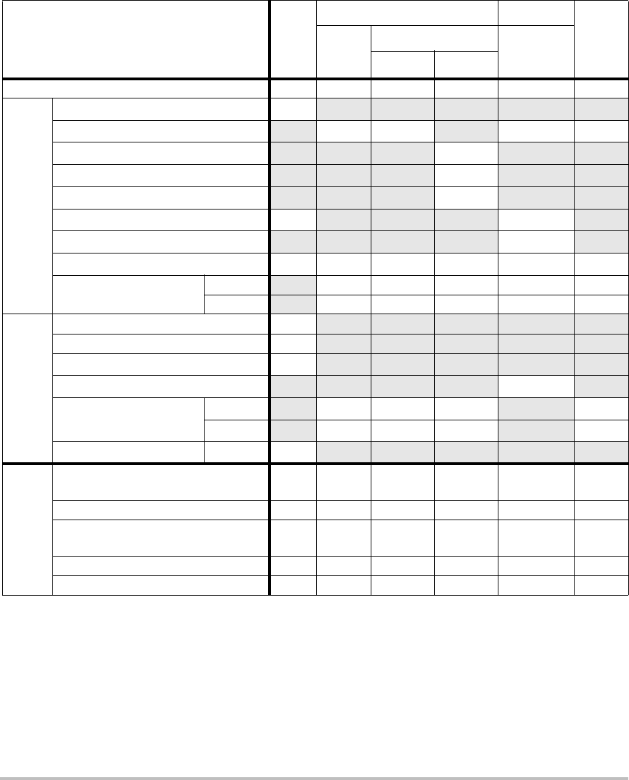
110
(a) This index is not required for this operating mode; value is <1.
(b) This transducer is not intended for transcranial or neonatal cephalic uses.
#No data are reported for this operating condition since the global maximum index value is not reported for
the reason listed. (Reference Global Maximum Index Value line.)
— Data are not applicable for this transducer/mode.
Table 10: Transducer Model: C60x/5-2 Operating Mode: 2D
Index Label M.I.
TIS TIB
TIC
Scan
Non-scan
Non-scan
Aaprt≤1A
aprt>1
Global Maximum Index Value 1.0 (a) — — — (b)
Associated Acoustic
Parameter
pr.3 (MPa) 1.69
W0(mW) #— —#
min of [W.3(z1),ITA.3(z1)] (mW) —
z1(cm) —
zbp (cm) —
zsp (cm) 4.7 —
deq(zsp)(cm) —
fc(MHz) 2.84 # — — — #
Dim of Aaprt X(cm) #—— — #
Y(cm) #—— — #
Other Information
PD (μsec) 0.579
PRF (Hz) 5440
pr@PIImax (MPa) 2.679
deq@Pllmax (cm) —
Focal Length FLx (cm) #—— #
FLy (cm) #—— #
IPA.3@MImax (W/cm2)197.7
Operating
Control
Conditions
Control 1: Exam Type Abd/
OB
Control 2: Optimization Any
Control 3: Depth 11/
13 cm
Control 4: THI On
Control 5: MB (Multi Beam) On

Chapter 6: Safety 111
Safety
(a) This index is not required for this operating mode; value is <1.
(b) This transducer is not intended for transcranial or neonatal cephalic uses.
#No data are reported for this operating condition since the global maximum index value is not reported for
the reason listed. (Reference Global Maximum Index Value line.)
— Data are not applicable for this transducer/mode.
Table 11: Transducer Model: C60x/5-2 Operating Mode: MMode
Index Label M.I.
TIS TIB
TIC
Scan
Non-scan
Non-scan
Aaprt≤1A
aprt>1
Global Maximum Index Value 1.0 — (a) — (a) (b)
Associated Acoustic
Parameter
pr.3 (MPa) 1.62
W0(mW) —# ##
min of [W.3(z1),ITA.3(z1)] (mW) —
z1(cm) —
zbp (cm) —
zsp (cm) 4.7 #
deq(zsp)(cm) #
fc(MHz) 2.85 — # — # #
Dim of Aaprt X(cm) —# — # #
Y(cm) —# — # #
Other Information
PD (μsec) 0.577
PRF (Hz) 800
pr@PIImax (MPa) 2.576
deq@Pllmax (cm) #
Focal Length FLx (cm) —# — #
FLy (cm) —# — #
IPA.3@MImax (W/cm2)184.3
Operating
Control
Conditions
Control 1: Exam Type Any
Control 2: Optimization Pen
Control 3: Depth 7.8 cm
Control 4: MB (Multi Beam) Off or
On

112
(a) This index is not required for this operating mode; value is <1.
(b) This transducer is not intended for transcranial or neonatal cephalic uses.
#No data are reported for this operating condition since the global maximum index value is not reported for
the reason listed. (Reference Global Maximum Index Value line.)
— Data are not applicable for this transducer/mode.
Table 12: Transducer Model: C60x/5-2 Operating Mode: PW Doppler
Index Label M.I.
TIS TIB
TIC
Scan
Non-scan
Non-scan
Aaprt≤1A
aprt>1
Global Maximum Index Value (a) — (a) — 3.1 (b)
Associated Acoustic
Parameter
pr.3 (MPa) #
W0(mW) —# 85.64 #
min of [W.3(z1),ITA.3(z1)] (mW) —
z1(cm) —
zbp (cm) —
zsp (cm) #1.255
deq(zsp)(cm) 0.51
fc(MHz) #— # — 2.233#
Dim of Aaprt X(cm) —# —0.6552#
Y(cm) —# — 1.3 #
Other Information
PD (μsec) #
PRF (Hz) #
pr@PIImax (MPa) #
deq@Pllmax (cm) 0.415
Focal Length FLx (cm) —# — #
FLy (cm) —# — #
IPA.3@MImax (W/cm2)#
Operating
Control
Conditions
Control 1: Exam Type Abd
Control 2: PRF Any
Control 3: Sample Volume 12 mm
Control 4: Sample Volume Position Zone 1

Chapter 6: Safety 113
Safety
(a) This index is not required for this operating mode; value is <1.
(b) This transducer is not intended for transcranial or neonatal cephalic uses.
#No data are reported for this operating condition since the global maximum index value is not reported for
the reason listed. (Reference Global Maximum Index Value line.)
— Data are not applicable for this transducer/mode.
Table 13: Transducer Model: D2x/2 Operating Mode: CW Doppler
Index Label M.I.
TIS TIB
TIC
Scan
Non-scan
Non-scan
Aaprt≤1A
aprt>1
Global Maximum Index Value (a) — (a) — 2.6 (b)
Associated Acoustic
Parameter
pr.3 (MPa) #
W0(mW) —# 90.52 #
min of [W.3(z1),ITA.3(z1)] (mW) —
z1(cm) —
zbp (cm) —
zsp (cm) #1.1
deq(zsp)(cm) 0.66
fc(MHz) #— # — 2.00 #
Dim of Aaprt X(cm) —# — 0.8 #
Y(cm) —# — 0.4 #
Other Information
PD (μsec) #
PRF (Hz) #
pr@PIImax (MPa) #
deq@Pllmax (cm) 0.54
Focal Length FLx (cm) —# — #
FLy (cm) —# — #
IPA.3@MImax (W/cm2)#
Operating
Control
Conditions
Control 1: Exam Type Crd
Control 2: Depth Fixed
Control 3: Zone Fixed
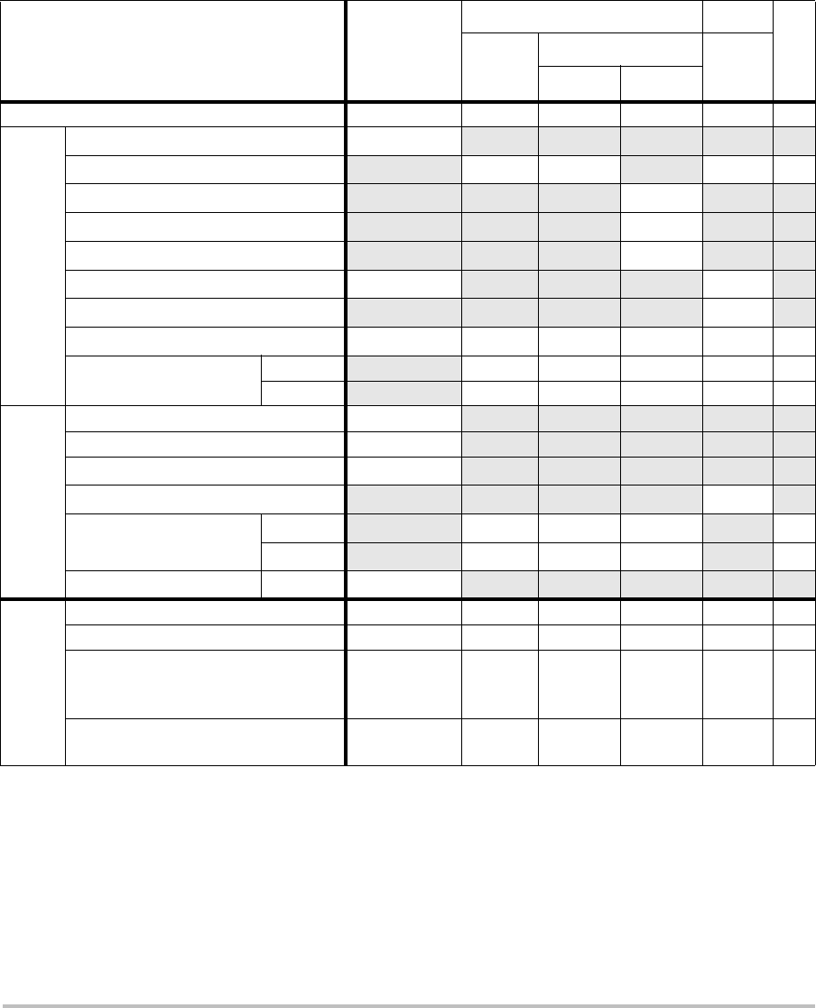
114
(a) This index is not required for this operating mode; value is <1.
(b) This transducer is not intended for transcranial or neonatal cephalic uses.
#No data are reported for this operating condition since the global maximum index value is not reported for
the reason listed. (Reference Global Maximum Index Value line.)
— Data are not applicable for this transducer/mode.
Table 14: Transducer Model: HFL38x/13-6 Operating Mode: CPD/Color
Index Label M.I.
TIS TIB
TIC
Scan
Non-scan Non-
scan
Aaprt≤1A
aprt>1
Global Maximum Index Value 1.1 1.0 — — — (b)
Associated Acoustic
Parameter
pr.3 (MPa) 2.556
W0(mW) 53.49 — —#
min of [W.3(z1),ITA.3(z1)] (mW) —
z1(cm) —
zbp (cm) —
zsp (cm) 1.2 —
deq(zsp)(cm) —
fc(MHz) 5.328 5.324 — — — #
Dim of Aaprt X(cm) 0.44 — — — #
Y(cm) 0.4 — — — #
Other Information
PD (μsec) 0.525
PRF (Hz) 2597
pr@PIImax (MPa) 3.187
deq@Pllmax (cm) —
Focal Length FLx (cm) 1.32 — — #
FLy (cm) 2.5 — — #
IPA.3@MImax (W/cm2)325.5
Operating
Control
Conditions
Control 1: Mode Color Color
Control 2: Exam Type Any Any
Control 3: Optimization/Depth/PRF Low/3.3 cm/
393
Med/
2.7 cm/
1938
Control 4: Color Box Position/Size Any Top/
Short

Chapter 6: Safety 115
Safety
(a) This index is not required for this operating mode; value is <1.
(b) This transducer is not intended for transcranial or neonatal cephalic uses.
#No data are reported for this operating condition since the global maximum index value is not reported for
the reason listed. (Reference Global Maximum Index Value line.)
— Data are not applicable for this transducer/mode.
Table 15: Transducer Model: HFL38x/13-6 Operating Mode: PW Doppler
Index Label M.I.
TIS TIB
TIC
Scan
Non-scan
Non-scan
Aaprt≤1A
aprt>1
Global Maximum Index Value 1.0 — 1.2 — 2.2 (b)
Associated Acoustic
Parameter
pr.3 (MPa) 2.37
W0(mW) — 46.55 46.55 #
min of [W.3(z1),ITA.3(z1)] (mW) —
z1(cm) —
zbp (cm) —
zsp (cm) 0.9 1.1
deq(zsp)(cm) 0.33
fc(MHz) 5.32 — 5.33 — 5.33 #
Dim of Aaprt X(cm) —1.04 — 1.04 #
Y(cm) — 0.4 — 0.4 #
Other Information
PD (μsec) 1.29
PRF (Hz) 1008
pr@PIImax (MPa) 2.404
deq@Pllmax (cm) 0.46
Focal Length FLx (cm) —3.72 — #
FLy (cm) —2.5 — #
IPA.3@MImax (W/cm2)323.35
Operating
Control
Conditions
Control 1: Exam Type Bre/Vas
SmP/IMT
Vas/Ven/
IMT
Vas/Ven/
IMT
Control 2: Sample Volume 1 mm 12 mm 12 mm
Control 3: PRF 1008 10417 10417
Control 4: Sample Volume Position Zone 2 Zone 7 Zone 7
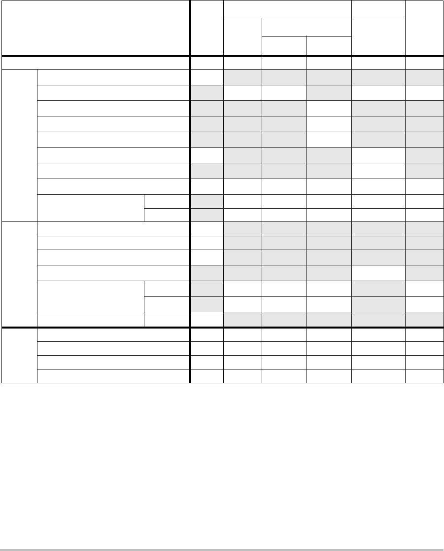
116
(a) This index is not required for this operating mode; value is <1.
(b) This transducer is not intended for transcranial or neonatal cephalic uses.
#No data are reported for this operating condition since the global maximum index value is not reported for
the reason listed. (Reference Global Maximum Index Value line.)
— Data are not applicable for this transducer/mode.
Table 16: Transducer Model: ICTx/8-5 Operating Mode: PW Doppler
Index Label M.I.
TIS TIB
TIC
Scan
Non-scan
Non-scan
Aaprt≤1A
aprt>1
Global Maximum Index Value (a) — (a) — 1.2 (a)
Associated Acoustic
Parameter
pr.3 (MPa) #
W0(mW) —# 16.348 #
min of [W.3(z1),ITA.3(z1)] (mW) —
z1(cm) —
zbp (cm) —
zsp (cm) #1.6
deq(zsp)(cm) 0.192
fc(MHz) # — # — 4.36 #
Dim of Aaprt X(cm) —# — 0.6 #
Y(cm) —# — 0.5 #
Other Information
PD (μsec) #
PRF (Hz) #
pr@PIImax (MPa) #
deq@Pllmax (cm) 0.187
Focal Length FLx (cm) —# — #
FLy (cm) —# — #
IPA.3@MImax (W/cm2)#
Operating
Control
Conditions
Control 1: Exam Type Any
Control 2: Sample Volume 3 mm
Control 3: PRF Any
Control 4: Sample Volume Position Zone 1
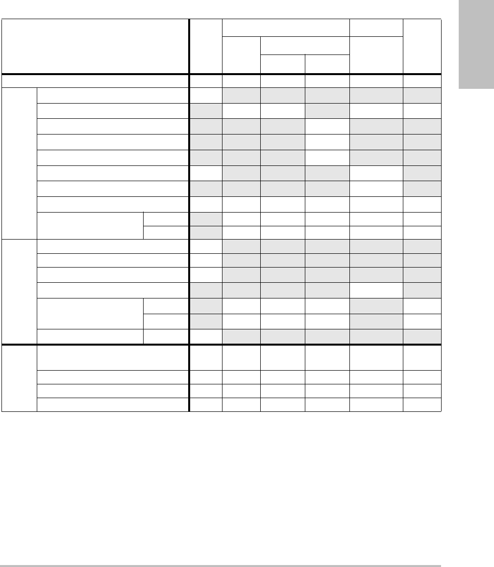
Chapter 6: Safety 117
Safety
(a) This index is not required for this operating mode; value is <1.
(b) This transducer is not intended for transcranial or neonatal cephalic uses.
#No data are reported for this operating condition since the global maximum index value is not reported for
the reason listed. (Reference Global Maximum Index Value line.)
— Data are not applicable for this transducer/mode.
Table 17: Transducer Model L25x/13-6 Operating Mode: PW Doppler
Index Label M.I.
TIS TIB
TIC
Scan
Non-scan
Non-scan
Aaprt≤1A
aprt>1
Global Maximum Index Value (a) — (a) — 1.6 (b)
Associated Acoustic
Parameter
pr.3 (MPa) #
W0(mW) —# 14.02 #
min of [W.3(z1),ITA.3(z1)] (mW) —
z1(cm) —
zbp (cm) —
zsp (cm) #0.6
deq(zsp)(cm) 0.155
fc(MHz) #— # — 6.00 #
Dim of Aaprt X(cm) —# — 0.16#
Y(cm) —# — 0.3 #
Other Information
PD (μsec) #
PRF (Hz) #
pr@PIImax (MPa) #
deq@Pllmax (cm) 0.1549
Focal Length FLx (cm) —# — #
FLy (cm) —# — #
IPA.3@MImax (W/cm2)#
Operating
Control
Conditions
Control 1: Exam Type Vas/Nrv/
Ven
Control 2: Sample Volume 12 mm
Control 3: PRF 20833
Control 4: Sample Volume Position Zone 0
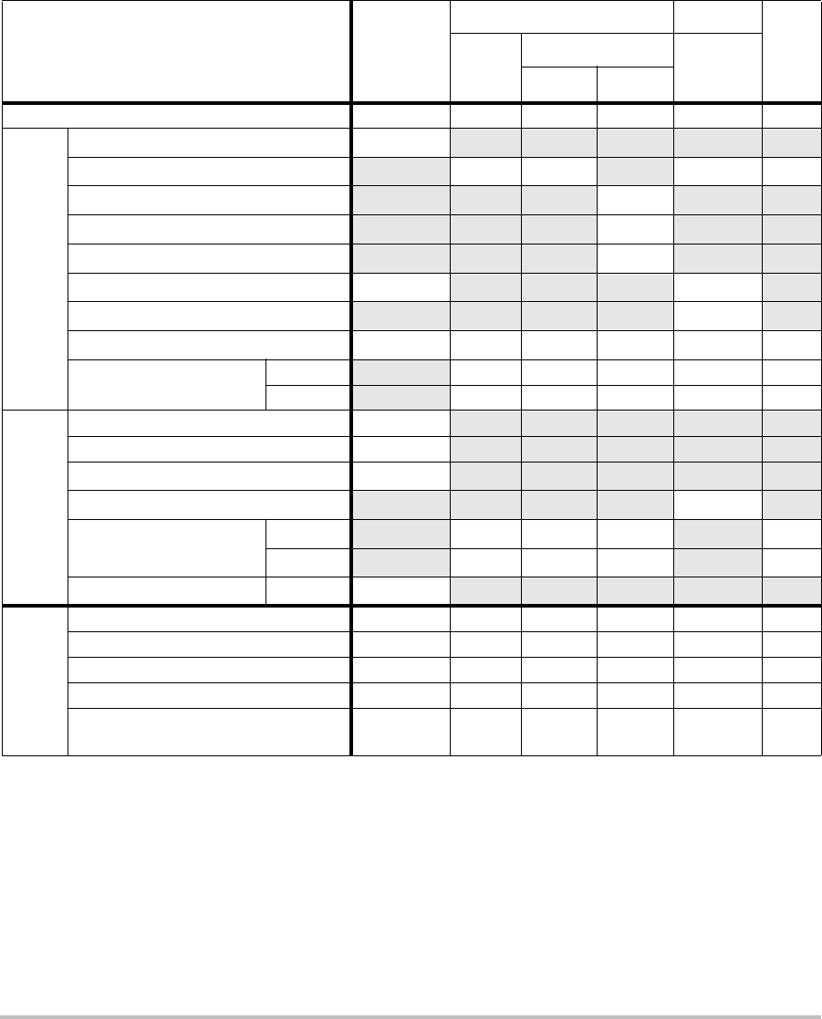
118
(a) This index is not required for this operating mode; value is <1.
(b) This transducer is not intended for transcranial or neonatal cephalic uses.
#No data are reported for this operating condition since the global maximum index value is not reported for
the reason listed. (Reference Global Maximum Index Value line.)
— Data are not applicable for this transducer/mode.
Table 18: Transducer Model: L38x/10-5 Operating Mode: CPD/Color
Index Label M.I.
TIS TIB
TIC
Scan
Non-scan
Non-scan
Aaprt≤1A
aprt>1
Global Maximum Index Value 1.3 1.0 — — — (b)
Associated Acoustic
Parameter
pr.3 (MPa) 2.89
W0(mW) 64.88 — —#
min of [W.3(z1),ITA.3(z1)] (mW) —
z1(cm) —
zbp (cm) —
zsp (cm) 1.1 —
deq(zsp)(cm) —
fc(MHz) 4.91 4.91 — — — #
Dim of Aaprt X(cm) 0.54 — — — #
Y(cm) 0.4 — — — #
Other Information
PD (μsec) 0.529
PRF (Hz) 9547
pr@PIImax (MPa) 3.48
deq@Pllmax (cm) —
Focal Length FLx (cm) 1.5 — — #
FLy (cm) 2.5 — — #
IPA.3@MImax (W/cm2)439.3
Operating
Control
Conditions
Control 1: Mode Color CPD
Control 2: Exam Type Any Bre
Control 3: PRF 331 2137
Control 4: Optimization/Depth Any/3.1 Med/3.1
Control 5: Color Box Position/Size Any Def/
Def/Def

Chapter 6: Safety 119
Safety
(a) This index is not required for this operating mode; value is <1.
(b) This transducer is not intended for transcranial or neonatal cephalic uses.
#No data are reported for this operating condition since the global maximum index value is not reported for
the reason listed. (Reference Global Maximum Index Value line.)
— Data are not applicable for this transducer/mode.
Table 19: Transducer Model: L38x/10-5 Operating Mode: PW Doppler
Index Label M.I.
TIS TIB
TIC
Scan
Non-scan
Non-scan
Aaprt≤1A
aprt>1
Global Maximum Index Value 1.04 — 2.0 — 2.6 (b)
Associated Acoustic
Parameter
pr.3 (MPa) 2.345
W0(mW) —84.94 84.94 #
min of [W.3(z1),ITA.3(z1)] (mW) —
z1(cm) —
zbp (cm) —
zsp (cm) 0.8 1.3
deq(zsp)(cm) 0.4685
fc(MHz) 5.01 — 5.05 — 5.05 #
Dim of Aaprt X(cm) — 1.80 — 1.80 #
Y(cm) — 0.4 — 0.4 #
Other Information
PD (μsec) 1.29
PRF (Hz) 1008
pr@PIImax (MPa) 2.693
deq@Pllmax (cm) 0.2533
Focal Length FLx (cm) —5.54 — #
FLy (cm) —2.5 — #
IPA.3@MImax (W/cm2)284.5
Operating
Control
Conditions
Control 1: Exam Type Any Vas Vas
Control 2: Sample Volume 1 mm 12 mm 12 mm
Control 3: PRF 1008 Any Any
Control 4: Sample Volume Position Zone 0
(top) Zone 7 Zone 7

120
(a) This index is not required for this operating mode; value is <1.
(b) This transducer is not intended for transcranial or neonatal cephalic uses.
#No data are reported for this operating condition since the global maximum index value is not reported for
the reason listed. (Reference Global Maximum Index Value line.)
— Data are not applicable for this transducer/mode.
Table 20: Transducer Model: P10x/8-4 Operating Mode: 2D Mode
Index Label M.I.
TIS TIB
TIC
Scan
Non-scan
Non-scan
Aaprt≤1A
aprt>1
Global Maximum Index Value (a) (a) — — — 1.0
Associated Acoustic
Parameter
pr.3 (MPa) #
W0(mW) #— —35.24
min of [W.3(z1),ITA.3(z1)] (mW) —
z1(cm) —
zbp (cm) —
zsp (cm) #—
deq(zsp)(cm) —
fc(MHz) ## — — — 4.84
Dim of Aaprt X(cm) # — — — 0.416
Y(cm) #—— —0.7
Other Information
PD (μsec) #
PRF (Hz) #
pr@PIImax (MPa) #
deq@Pllmax (cm) —
Focal Length FLx (cm) #—— 1.67
FLy (cm) #—— 5.0
IPA.3@MImax (W/cm2)#
Operating
Control
Conditions
Control 1: Exam Type Neo
Control 2: Optimization Gen
Control 3: Depth 2.0
Control 4: MB/SonoHD Off/Off

Chapter 6: Safety 121
Safety
(a) This index is not required for this operating mode; value is <1.
(b) This transducer is not intended for transcranial or neonatal cephalic uses.
#No data are reported for this operating condition since the global maximum index value is not reported for
the reason listed. (Reference Global Maximum Index Value line.)
— Data are not applicable for this transducer/mode.
Table 21: Transducer Model: P10x/8-4 Operating Mode: Color
Index Label M.I.
TIS TIB
TIC
Scan
Non-scan
Non-scan
Aaprt≤1A
aprt>1
Global Maximum Index Value 1.0 (a) — — — 1.3
Associated Acoustic
Parameter
pr.3 (MPa) 2.02
W0(mW) #— — 41.38
min of [W.3(z1),ITA.3(z1)] (mW) —
z1(cm) —
zbp (cm) —
zsp (cm) 2.4 —
deq(zsp)(cm) —
fc(MHz) 3.90 # — — — 3.91
Dim of Aaprt X(cm) #— — —0.608
Y(cm) #— — —0.7
Other Information
PD (μsec) 0.70
PRF (Hz) 2772
pr@PIImax (MPa) 2.80
deq@Pllmax (cm) —
Focal Length FLx (cm) #— — 2.48
FLy (cm) #— — 5.0
IPA.3@MImax (W/cm2)252
Operating
Control
Conditions
Control 1: Mode Color Color
Control 2: Exam Type Neo Abd
Control 3: Optimization/Depth/PRF Low/
3.7/
772
Med/
2.0/
2315
Control 4: Color Box Pos/Size Any/
Tall
Short/
Narrow
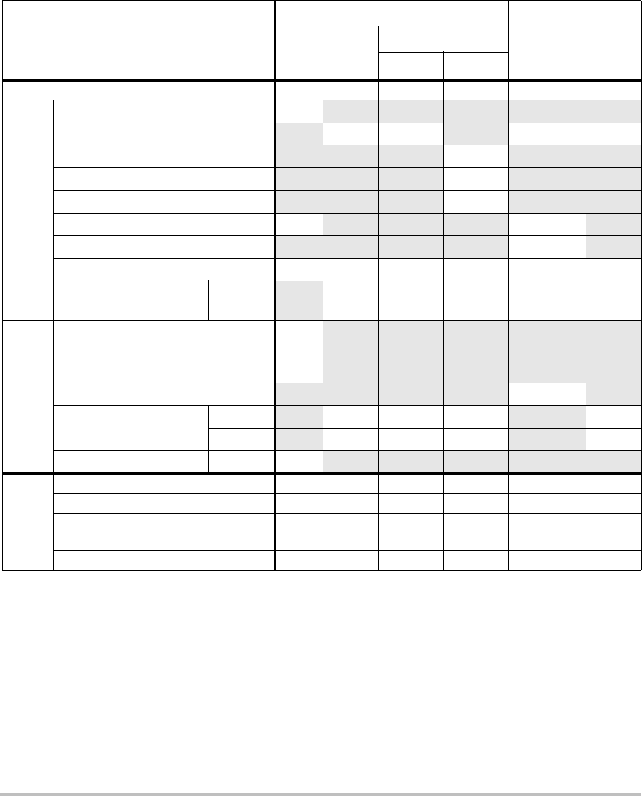
122
(a) This index is not required for this operating mode; value is <1.
(b) This transducer is not intended for transcranial or neonatal cephalic uses.
#No data are reported for this operating condition since the global maximum index value is not reported for
the reason listed. (Reference Global Maximum Index Value line.)
— Data are not applicable for this transducer/mode.
Table 22: Transducer Model: P10x/8-4 Operating Mode: PW Doppler
Index Label M.I.
TIS TIB
TIC
Scan
Non-scan
Non-scan
Aaprt≤1A
aprt>1
Global Maximum Index Value 1.0 — 1.2 — 2.0 1.8
Associated Acoustic
Parameter
pr.3 (MPa) 2.03
W0(mW) — 36.25 34.4 31.5
min of [W.3(z1),ITA.3(z1)] (mW) —
z1(cm) —
zbp (cm) —
zsp (cm) 2.1 0.8
deq(zsp)(cm) 0.32
fc(MHz) 3.87 — 6.86 — 3.84 3.86
Dim of Aaprt X(cm) — 0.992 — 0.416 .224
Y(cm) — 0.7 — 0.7 0.7
Other Information
PD (μsec) 1.28
PRF (Hz) 1563
pr@PIImax (MPa) 2.70
deq@Pllmax (cm) 0.25
Focal Length FLx (cm) —6.74 — 0.92
FLy (cm) —5.0 — 5.0
IPA.3@MImax (W/cm2)233
Operating
Control
Conditions
Control 1: Exam Type Crd Crd Neo Crd
Control 2: Sample Volume 1 mm 7 mm 12 mm 1 mm
Control 3: PRF/TDI 1563/
Off
Any/
On
15625/
Off
5208/
Off
Control 4: Sample Volume Position Zone 3 Zone 6 Zone 2 Zone 1
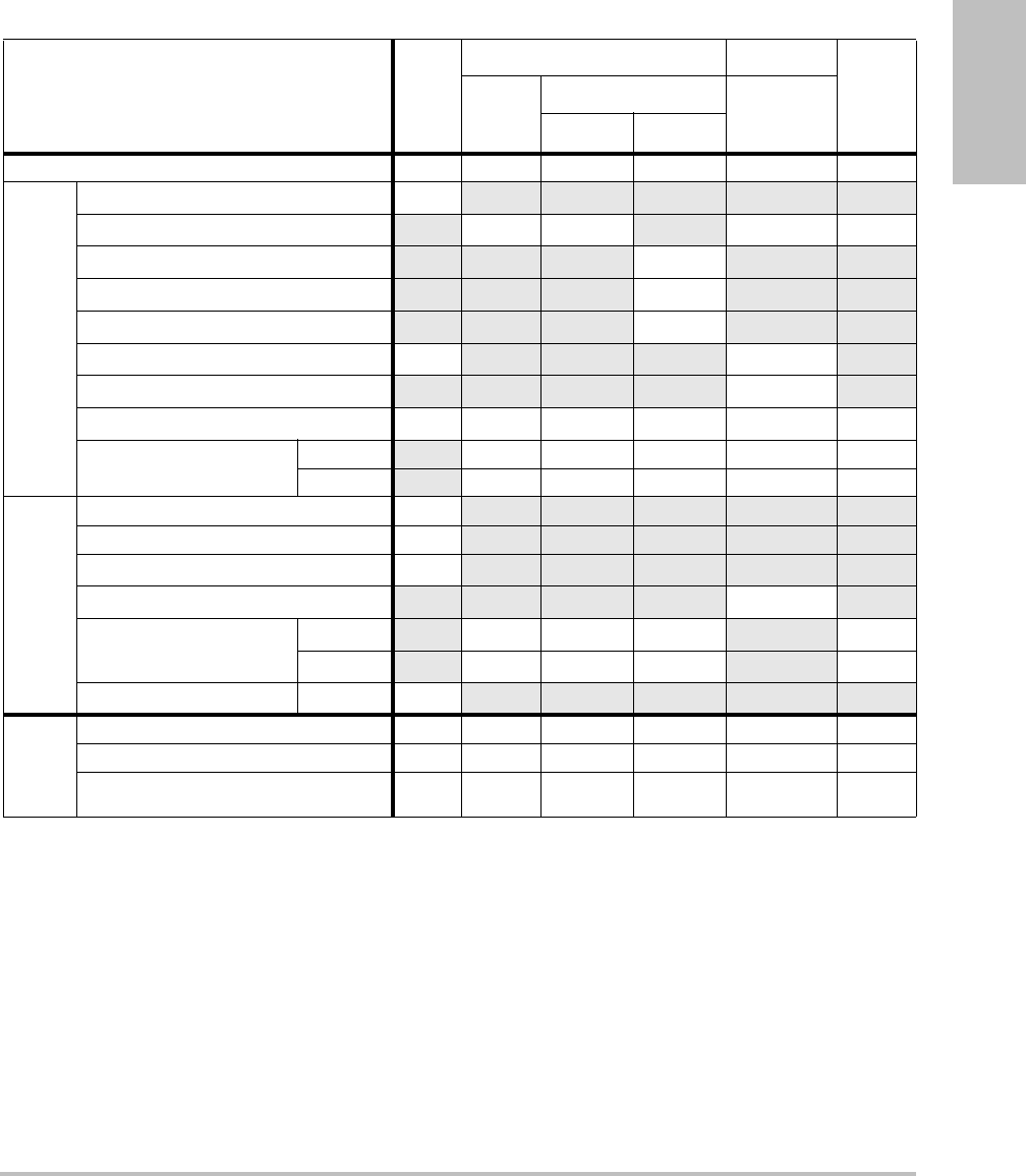
Chapter 6: Safety 123
Safety
(a) This index is not required for this operating mode; value is <1.
(b) This transducer is not intended for transcranial or neonatal cephalic uses.
#No data are reported for this operating condition since the global maximum index value is not reported for
the reason listed. (Reference Global Maximum Index Value line.)
— Data are not applicable for this transducer/mode.
Table 23: Transducer Model: P10x/8-4 Operating Mode: CW Doppler
Index Label M.I.
TIS TIB
TIC
Scan
Non-scan
Non-scan
Aaprt≤1A
aprt>1
Global Maximum Index Value (a) — (a) — 2.1 2.0
Associated Acoustic
Parameter
pr.3 (MPa) #
W0(mW) —# 40.72 30.00
min of [W.3(z1),ITA.3(z1)] (mW) —
z1(cm) —
zbp (cm) —
zsp (cm) #0.7
deq(zsp)(cm) 0.36
fc(MHz) # — # — 4.00 4.00
Dim of Aaprt X(cm) — # — 0.320 0.16
Y(cm) —# — 0.70.7
Other Information
PD (μsec) #
PRF (Hz) #
pr@PIImax (MPa) #
deq@Pllmax (cm) 0.27
Focal Length FLx (cm) —# — 0.92
FLy (cm) —# — 5.0
IPA.3@MImax (W/cm2)#
Operating
Control
Conditions
Control 1: Exam Type Card Card
Control 2: Depth Any Any
Control 3: Zone Zone 3 Zone 0
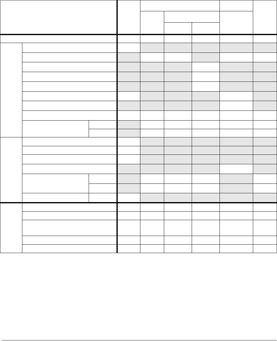
124
(a) This index is not required for this operating mode; value is <1.
(b) This transducer is not intended for transcranial or neonatal cephalic uses.
#No data are reported for this operating condition since the global maximum index value is not reported for
the reason listed. (Reference Global Maximum Index Value line.)
— Data are not applicable for this transducer/mode.
Table 24: Transducer Model: P21x/5-1 Operating Mode: 2D
Index Label M.I.
TIS TIB
TIC
Scan
Non-scan
Non-scan
Aaprt≤1A
aprt>1
Global Maximum Index Value 1.4 (a) — — — 2.3
Associated Acoustic
Parameter
pr.3 (MPa) 1.92
W0(mW) #— —171.53
min of [W.3(z1),ITA.3(z1)] (mW) —
z1(cm) —
zbp (cm) —
zsp (cm) 5.1 —
deq(zsp)(cm) —
fc(MHz) 1.93 # — — — 1.94
Dim of Aaprt X(cm) #—— —1.9
Y(cm) #—— —1.3
Other Information
PD (μsec) 0.842
PRF (Hz) 4000
pr@PIImax (MPa) 2.53
deq@Pllmax (cm) —
Focal Length FLx (cm) #—— 18.46
FLy (cm) #—— 5.5
IPA.3@MImax (W/cm2)355.1
Operating
Control
Conditions
Control 1: Exam Type Card Card
Control 2: Optimization Res Pen
Control 3: Depth 4.7/7.5
cm 27 cm
Control 4: THI On Off
Control 5: Sector Width Narrow Narrow
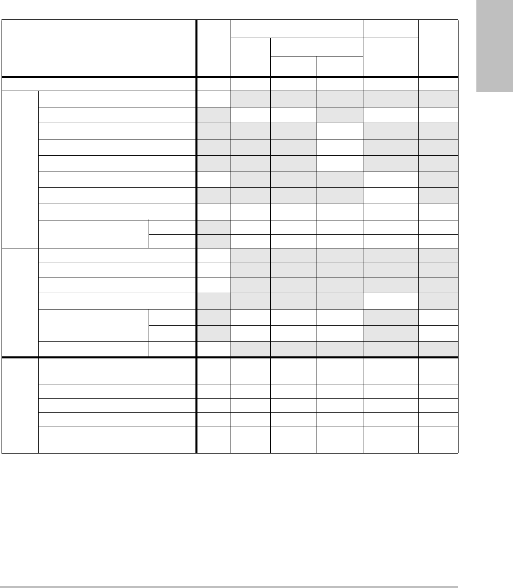
Chapter 6: Safety 125
Safety
(a) This index is not required for this operating mode; value is <1.
(b) This transducer is not intended for transcranial or neonatal cephalic uses.
#No data are reported for this operating condition since the global maximum index value is not reported for
the reason listed. (Reference Global Maximum Index Value line.)
— Data are not applicable for this transducer/mode.
Table 25: Transducer Model: P21x/5-1 Operating Mode: MMode
Index Label M.I.
TIS TIB
TIC
Scan
Non-scan
Non-scan
Aaprt≤1A
aprt>1
Global Maximum Index Value 1.5 — (a) — 1.4 1.1
Associated Acoustic
Parameter
pr.3 (MPa) 2.10
W0(mW) —# 40.08 29.71
min of [W.3(z1),ITA.3(z1)] (mW) —
z1(cm) —
zbp (cm) —
zsp (cm) 3.645 4.9
deq(zsp)(cm) 0.343
fc(MHz) 1.93 — # — 1.93 1.94
Dim of Aaprt X(cm) — # — 1.835 1.9
Y(cm) —# — 1.31.3
Other Information
PD (μsec) 0.904
PRF (Hz) 800
pr@PIImax (MPa) 2.679
deq@Pllmax (cm) 0.341
Focal Length FLx (cm) —# — 18.46
FLy (cm) —# — 5.5
IPA.3@MImax (W/cm2)237.4
Operating
Control
Conditions
Control 1: Exam Type Abd/
OB Abd/OB Abd/OB
/Card
Control 2: Optimization Any Gen/Res Pen
Control 3: Depth 7.5 cm 10/13 cm 27 cm
Control 4: THI On On Off
Control 5: MB
(Multibeam) On On or Off On or
Off
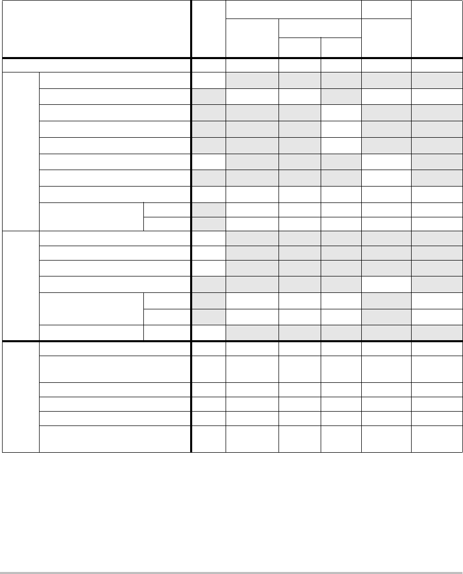
126
(a) This index is not required for this operating mode; value is <1.
(b) This transducer is not intended for transcranial or neonatal cephalic uses.
#No data are reported for this operating condition since the global maximum index value is not reported for
the reason listed. (Reference Global Maximum Index Value line.)
— Data are not applicable for this transducer/mode.
Table 26: Transducer Model: P21x/5-1 Operating Mode: CPD/Color
Index Label M.I.
TIS TIB
TIC
Scan
Non-scan
Non-scan
Aaprt≤1A
aprt>1
Global Maximum Index Value 1.5 1.3 — — — 2.4
Associated Acoustic
Parameter
pr.3 (MPa) 2.19
W0(mW) 136.91 — — 137.5
min of [W.3(z1),ITA.3(z1)] (mW) —
z1(cm) —
zbp (cm) —
zsp (cm) 4.5 —
deq(zsp)(cm) —
fc(MHz) 2.15 2.16 — — — 2.16
Dim of Aaprt X(cm) 0.918 — — — 0.918
Y(cm) 1.3 — — — 1.3
Other Information
PD (μsec) 1.20
PRF (Hz) 1063
pr@PIImax (MPa) 2.574
deq@Pllmax (cm) —
Focal Length FLx (cm) 3.68 — — 3.68
FLy (cm) 5.5 — — 5.5
IPA.3@MImax (W/cm2)330.4
Operating
Control
Conditions
Control 1: Mode Color CPD Color
Control 2: Exam Type Abd/
OB OB Abd
Control 3: PRF/Depth 300/10 850/7.5 751/7.5
Control 4: Color Optimization Any Med Med
Control 5: THI On Off Off
Control 6: Color Box Size Any Short and
Narrow
Short and
Narrow
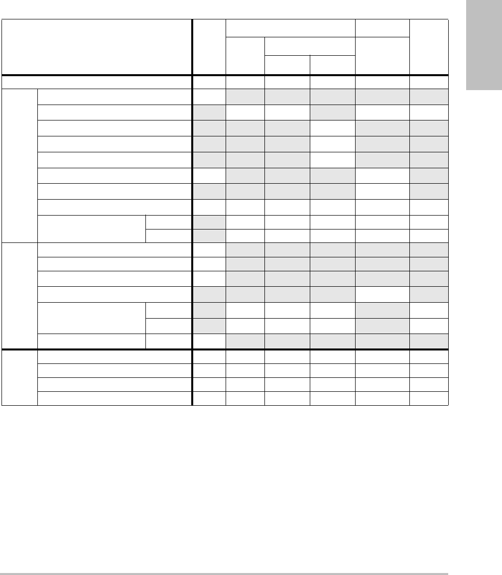
Chapter 6: Safety 127
Safety
(a) This index is not required for this operating mode; value is <1.
(b) This transducer is not intended for transcranial or neonatal cephalic uses.
#No data are reported for this operating condition since the global maximum index value is not reported for
the reason listed. (Reference Global Maximum Index Value line.)
— Data are not applicable for this transducer/mode.
Table 27: Transducer Model: P21x/5-1 Operating Mode: PW Doppler
Index Label M.I.
TIS TIB
TIC
Scan
Non-scan
Non-scan
Aaprt≤1A
aprt>1
Global Maximum Index Value 1.2 — — 1.3 4.0 2.7
Associated Acoustic
Parameter
pr.3 (MPa) 1.844
W0(mW) —— 95.55 95.55
min of [W.3(z1),ITA.3(z1)] (mW) 120.13
z1(cm) 3.1
zbp (cm) 2.66
zsp (cm) 3.718 0.6
deq(zsp)(cm) 0.49
fc(MHz) 2.16 — — 2.22 2.23 2.23
Dim of Aaprt X(cm) — — 1.9 0.459 0.459
Y(cm) — — 1.3 1.3 1.3
Other Information
PD (μsec) 1.21
PRF (Hz) 1562.5
pr@PIImax (MPa) 2.432
deq@Pllmax (cm) 0.49
Focal Length FLx (cm) ——13.84 1.55
FLy (cm) —— 5.5 5.5
IPA.3@MImax (W/cm2)187.5
Operating
Control
Conditions
Control 1: Exam Type Card Card TCD TCD
Control 2: Sample Volume 1mm 3mm 14mm 14mm
Control 3: PRF 1563 3906 12500 12500
Control 4: Sample Volume Position Zone 1 Zone 4 Zone 0 Zone 0
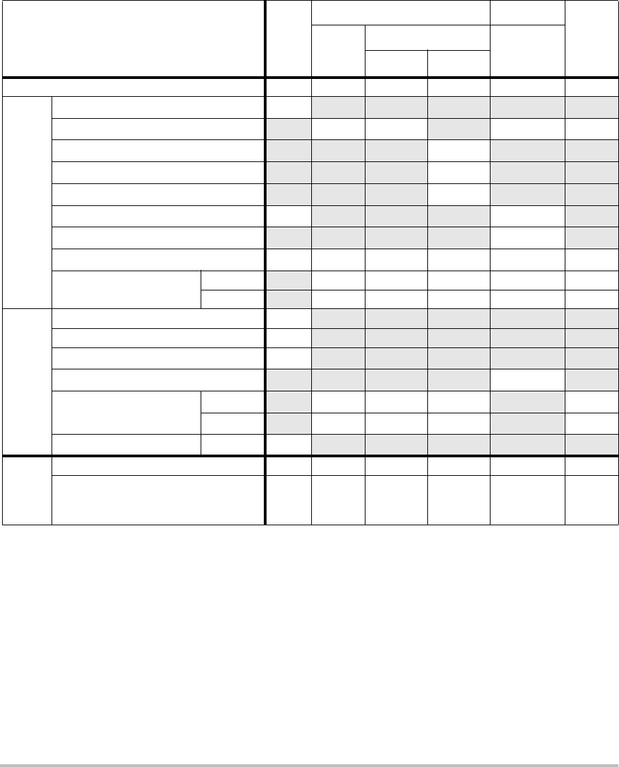
128
(a) This index is not required for this operating mode; value is <1.
(b) This transducer is not intended for transcranial or neonatal cephalic uses.
#No data are reported for this operating condition since the global maximum index value is not reported for
the reason listed. (Reference Global Maximum Index Value line.)
— Data are not applicable for this transducer/mode.
Table 28: Transducer Model: P21x/5-1 Operating Mode: CW Doppler
Index Label M.I.
TIS TIB
TIC
Scan
Non-scan
Non-scan
Aaprt≤1A
aprt>1
Global Maximum Index Value (a) — — 1.0 3.4 2.9
Associated Acoustic
Parameter
pr.3 (MPa) #
W0(mW) —— 88.30 101.73
min of [W.3(z1),ITA.3(z1)] (mW) 102.54
z1(cm) 1.386
zbp (cm) 1.71
zsp (cm) #1.255
deq(zsp)(cm) 0.49
fc(MHz) # — — 2.00 2.00 2.00
Dim of Aaprt X(cm) — — 0.786 0.655 0.459
Y(cm) —— 1.3 1.3 1.3
Other Information
PD (μsec) #
PRF (Hz) #
pr@PIImax (MPa) #
deq@Pllmax (cm) 0.45
Focal Length FLx (cm) ——13.84 1.55
FLy (cm) —— 5.5 5.5
IPA.3@MImax (W/cm2)#
Operating
Control
Conditions
Control 1: Exam Type Card Card Card
Control 2: Zone
Zone 4 Zone 1 Zone 0
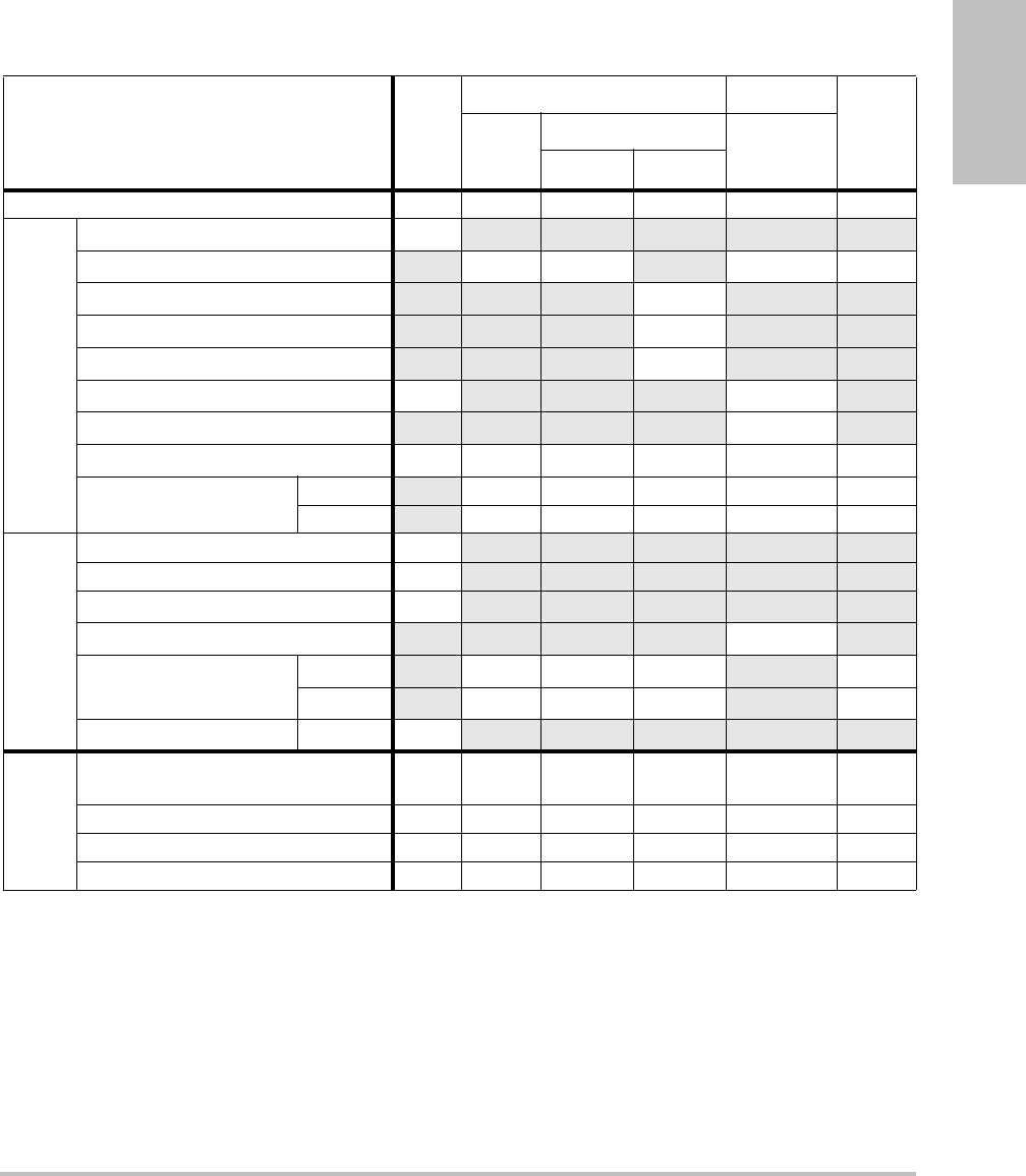
Chapter 6: Safety 129
Safety
(a) This index is not required for this operating mode; value is <1.
(b) This transducer is not intended for transcranial or neonatal cephalic uses.
#No data are reported for this operating condition since the global maximum index value is not reported for
the reason listed. (Reference Global Maximum Index Value line.)
— Data are not applicable for this transducer/mode.
Table 29: Transducer Model: SLAx/13-6 Operating Mode: PW Doppler
Index Label M.I.
TIS TIB
TIC
Scan
Non-scan
Non-scan
Aaprt≤1A
aprt>1
Global Maximum Index Value (a) — (a) — 1.2 (b)
Associated Acoustic
Parameter
pr.3 (MPa) #
W0(mW) —# 8.75 #
min of [W.3(z1),ITA.3(z1)] (mW) —
z1(cm) —
zbp (cm) —
zsp (cm) #0.65
deq(zsp)(cm) 0.13
fc(MHz) #— # — 6.00 #
Dim of Aaprt X(cm) —# — 0.24#
Y(cm) —# — 0.3 #
Other Information
PD (μsec) #
PRF (Hz) #
pr@PIImax (MPa) #
deq@Pllmax (cm) 0.13
Focal Length FLx (cm) —# — #
FLy (cm) —# — #
IPA.3@MImax (W/cm2)#
Operating
Control
Conditions
Control 1: Exam Type Vas, Nrv,
Ven
Control 2: Sample Volume 5 mm
Control 3: PRF 20833
Control 4: Sample Vol. Position Zone 2
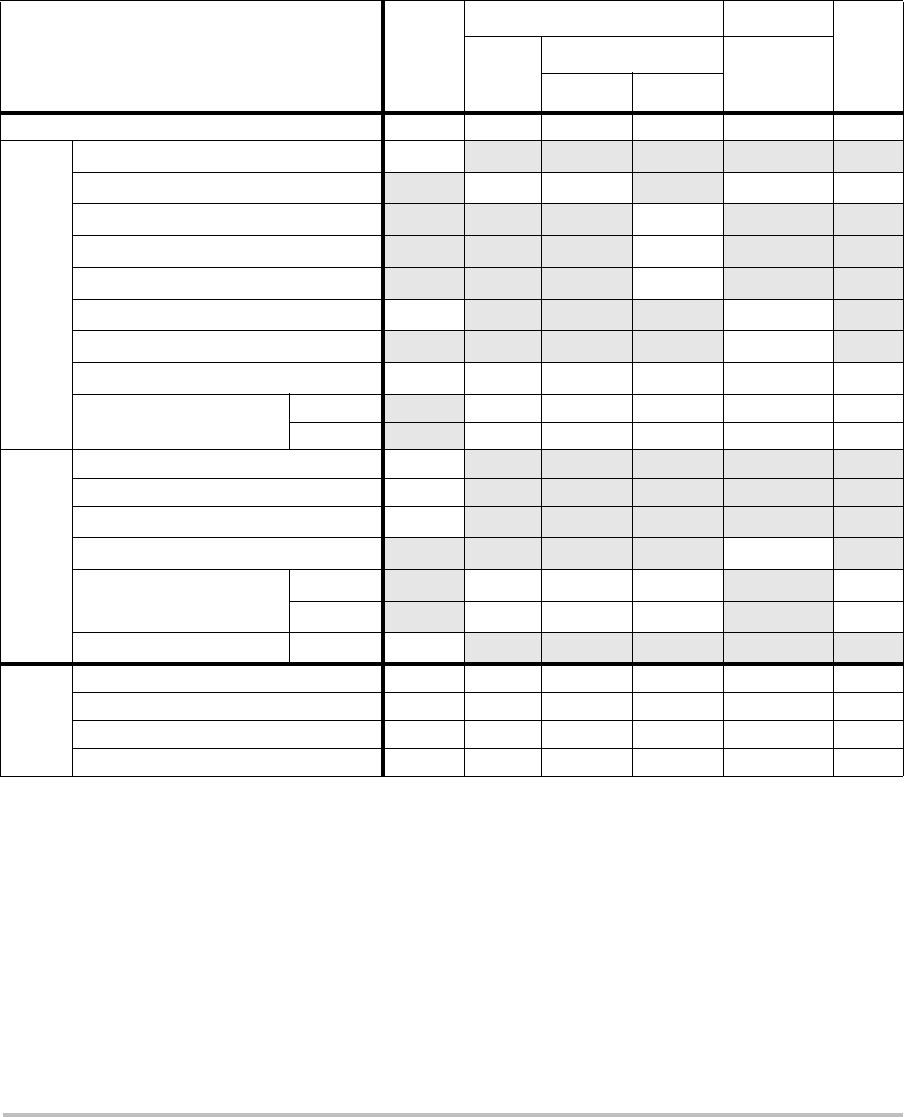
130
(a) This index is not required for this operating mode; value is <1.
(b) This transducer is not intended for transcranial or neonatal cephalic uses.
#No data are reported for this operating condition since the global maximum index value is not reported for
the reason listed. (Reference Global Maximum Index Value line.)
— Data are not applicable for this transducer/mode.
Table 30: Transducer Model: TEEx/8-3 Operating Mode: PW Doppler
Index Label M.I.
TIS TIB
TIC
Scan
Non-scan
Non-scan
Aaprt≤1A
aprt>1
Global Maximum Index Value (a) — (a) — 1.7 (b)
Associated Acoustic
Parameter
pr.3 (MPa) #
W0(mW) —# 29.29 #
min of [W.3(z1),ITA.3(z1)] (mW) —
z1(cm) —
zbp (cm) —
zsp (cm) #0.6
deq(zsp)(cm) 0.34
fc(MHz) #— # — 3.84 #
Dim of Aaprt X(cm) —# —0.261#
Y(cm) —# — 0.9 #
Other Information
PD (μsec) #
PRF (Hz) #
pr@PIImax (MPa) #
deq@Pllmax (cm) 0.34
Focal Length FLx (cm) —# — #
FLy (cm) —# — #
IPA.3@MImax (W/cm2)#
Operating
Control
Conditions
Control 1: Exam Type Crd
Control 2: Sample Volume 1 mm
Control 3: PRF ≥ 2604
Control 4: Sample Volume Position Zone 1

Chapter 6: Safety 131
Safety
(a) This index is not required for this operating mode; value is <1.
(b) This transducer is not intended for transcranial or neonatal cephalic uses.
#No data are reported for this operating condition since the global maximum index value is not reported for
the reason listed. (Reference Global Maximum Index Value line.)
— Data are not applicable for this transducer/mode.
Table 31: Transducer Model: TEEx/8-3 Operating Mode: CW Doppler
Index Label M.I.
TIS TIB
TIC
Scan
Non-scan
Non-scan
Aaprt≤1A
aprt>1
Global Maximum Index Value (a) — (a) — 1.2 (b)
Associated Acoustic
Parameter
pr.3 (MPa) #
W0(mW) —# 27.23 #
min of [W.3(z1),ITA.3(z1)] (mW) —
z1(cm) —
zbp (cm) —
zsp (cm) #1.1
deq(zsp)(cm) 0.39
fc(MHz) #— # — 4.00 #
Dim of Aaprt X(cm) —# —0.435#
Y(cm) —# — 0.9 #
Other Information
PD (μsec) #
PRF (Hz) #
pr@PIImax (MPa) #
deq@Pllmax (cm) 0.34
Focal Length FLx (cm) —# — #
FLy (cm) —# — #
IPA.3@MImax (W/cm2)#
Operating
Control
Conditions
Control 1: Exam Type Crd
Control 2: Depth Any
Control 3: Zone Zone 3

132
Terms used in the acoustic output tables
Table 32: Acoustic Output Terms and Definitions
Term Definition
ISPTA.3 Derated spatial peak, temporal average intensity in units of milliwatts/cm2.
TI type Applicable thermal index for the transducer, imaging mode, and exam type.
TI value Thermal index value for the transducer, imaging mode, and exam type.
MI Mechanical index.
Ipa.3@MImax Derated pulse average intensity at the maximum MI in units of W/cm2.
TIS (Soft tissue thermal index) is a thermal index related to soft tissues. TIS scan is
the soft tissue thermal index in an auto-scanning mode. TIS non-scan is the
soft tissue thermal index in the non-autoscanning mode.
TIB (Bone thermal index) is a thermal index for applications in which the
ultrasound beam passes through soft tissue and a focal region is in the
immediate vicinity of bone. TIB non-scan is the bone thermal index in the
non-autoscanning mode.
TIC (Cranial bone thermal index) is the thermal index for applications in which
the ultrasound beam passes through bone near the beam entrance into the
body.
Aaprt Area of the active aperture measured in cm2.
Pr.3 Derated peak rarefactional pressure associated with the transmit pattern
giving rise to the value reported under MI (Megapascals).
Wo Ultrasonic power, except for TISscan, in which case it is the ultrasonic power
passing through a one centimeter window in units of milliwatts.
W.3(z1)Derated ultrasonic power at axial distance z1 in units of milliwatts.
ISPTA.3(z1)Derated spatial-peak temporal-average intensity at axial distance z1
(milliwatts per square centimeter).
z1Axial distance corresponding to the location of maximum [min(W.3(z), ITA.3(z)
x 1 cm2)], where z > zbp in centimeters.
zbp 1.69 in centimeters.
zsp For MI, the axial distance at which pr.3 is measured. For TIB, the axial distance
at which TIB is a global maximum (for example, zsp = zb.3) in centimeters.
Aaprt()

Chapter 6: Safety 133
Safety
Acoustic measurement precision and uncertainty
Alltableentrieshavebeenobtainedatthesameoperatingconditionsthatgiverisetothe
maximumindexvalueinthefirstcolumnofthetable.Measurementprecisionanduncertainty
forpower,pressure,intensity,andotherquantitiesthatareusedtoderivethevaluesinthe
acousticoutputtableareshowninthetablebelow.InaccordancewithSection 6.4oftheOutput
DisplayStandard,thefollowingmeasurementprecisionanduncertaintyvaluesare
determinedbymakingrepeatmeasurementsandstatingthestandarddeviationasa
percentage.
deq(z) Equivalent beam diameter as a function of axial distance z, and is equal to
, where ITA(z) is the temporal-average intensity as a
function of z in centimeters.
fc Center frequency in MHz.
Dim. of Aaprt Active aperture dimensions for the azimuthal (x) and elevational (y) planes in
centimeters.
PD Pulse duration (microseconds) associated with the transmit pattern giving
rise to the reported value of MI.
PRF Pulse repetition frequency associated with the transmit pattern giving rise to
the reported value of MI in Hertz.
pr@PIImax Peak rarefactional pressure at the point where the free-field, spatial-peak
pulse intensity integral is a maximum in Megapascals.
deq@PIImax Equivalent beam diameter at the point where the free-field, spatial-peak
pulse intensity integral is a maximum in centimeters.
FL Focal length, or azimuthal (x) and elevational (y) lengths, if different
measured in centimeters.
Table 32: Acoustic Output Terms and Definitions (Continued)
Term Definition
4π()⁄()Wo()ITA z()()⁄()
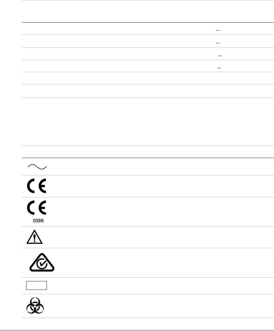
134
Labeling symbols
Thefollowingsymbolsareusedontheproducts,packaging,andcontainers.
Table 33: Acoustic Measurement Precision and Uncertainty
Quantity Precision
(% of standard deviation)
Uncertainty
(95% confidence)
Pr 1.9% +11.2%
Pr.3 1.9% +12.2%
Wo 3.4% +10%
fc 0.1% +4.7%
PII 3.2% +12.5 to -16.8%
PII.3 3.2% +13.47 to -17.5%
Table 34: Labeling Symbols
Symbol Definition
Alternating Current (AC)
Class 1 device indicating manufacturer’s declaration of conformance with
Annex VII of 93/42/EEC
Class 1 device requiring verification by the Notified Body of sterilization or
measurement features, or to a Class IIa, IIb, or III device requiring verification or
auditing by the Notified Body to applicable Annex(es) of 93/42/EEC
Attention, see the user guide
Device complies with relevant Australian regulations for electronic devices.
Batch code, date code, or lot code type of control number
Biological risk
LOT
Chapter 6: Safety 135
Safety
Device complies with relevant Brazilian regulations for electro-medical devices.
Canadian Standards Association. The “C” and “US” indicators next to this mark
signify that the product has been evaluated to the applicable CSA and ANSI/UL
Standards, for use in Canada and the US, respectively.
Catalog number
Collect separately from other household waste (see European Commission
Directive 93/86/EEC). Refer to local regulations for disposal.
Contents sterilized using ethylene oxide process.
Corrugated recycle
Dangerous voltage
Date of manufacture
Direct Current (DC)
Do not get wet.
Do not stack over 2 high.
Do not stack over 5 high.
Table 34: Labeling Symbols (Continued)
Symbol Definition
REF
STERILE EO
136
Do not stack over 10 high.
Electrostatic sensitive devices
Device complies with relevant FCC regulations for electronic devices.
Fragile
Gel sterilized by radiation.
Hot
Indoor use only
Device emits a static (DC) magnetic field.
Non-ionizing radiation
Paper recycle
Serial number type of control number
Storage temperature conditions
Submersible. Protected against the effects of temporary immersion.
Water-Tight Equipment. Protected against the effects of extended immersion.
Table 34: Labeling Symbols (Continued)
Symbol Definition
STERILE RGEL
SN
Chapter 6: Safety 137
Safety
Handle transducer with care.
Follow manufacturer’s instructions for disinfecting time.
Disinfect transducer.
Type BF patient applied part
(B = body, F = floating applied part)
Defibrillator proof type CF patient applied part
Underwriter’s Laboratories labeling
Pollution Control Logo. (Applies to all parts/products listed in the China RoHS
disclosure table. May not appear on the exterior of some parts/products
because of space limitations.)
China Compulsory Certificate mark (“CCC Mark”). A compulsory safety mark for
compliance to Chinese national standards for many products sold in the
People’s Republic of China.
Contains mercury. (Applies to the LCD and may apply to other components in
the ultrasound system.)
WARNING:
Connect Only
Accessories and
Peripherals
Recommended by
SonoSite
WARNING: Connect Only
Accessories and Peripherals
Recommended by SonoSite
Table 34: Labeling Symbols (Continued)
Symbol Definition

138

Chapter 7: References 139
References
Chapter 7: References
Measurement accuracy
Themeasurementsprovidedbythesystemdo
notdefineaspecificphysiologicaloranatomical
parameter.Rather,themeasurementsareofa
physicalpropertysuchasdistanceforevaluation
bytheclinician.Theaccuracyvaluesrequirethat
youcanplacethecalipersoveronepixel.The
valuesdonotincludeacousticanomaliesofthe
body.
The2Dlineardistancemeasurementresultsare
displayedincentimeterswithoneplacepastthe
decimalpoint,ifthemeasurementistenor
greater;twoplacespastthedecimalpoint,ifthe
measurementislessthanten.
Thelineardistancemeasurementcomponents
havetheaccuracyandrangeshowninthe
followingtables.
Table 1: 2D Measurement Accuracy and Range
2D Measure
Accuracy
and Range
System
Tolerancea
Accuracy
By
Test Methodb
Range (cm)
Axial
Distance
< ±2% plus
1% of full
scale
Acquisition Phantom 0-26 cm
Lateral
Distance
< ±2% plus
1% of full
scale
Acquisition Phantom 0-35 cm
Diagonal
Distance
< ±2% plus
1% of full
scale
Acquisition Phantom 0-44 cm
Areac< ±4% plus
(2% of full
scale/smallest
dimension) *
100 plus 0.5%
Acquisition Phantom 0.01-720
cm2
Circumfer-
enced
< ±3% plus
(1.4% of full
scale/
smallest
dimension) *
100 plus 0.5%
Acquisition Phantom 0.01-96
cm
a. Full scale for distance implies the maximum depth of the
image.
b. An RMI 413a model phantom with 0.7 dB/cm MHz attenuation
was used.
c. The area accuracy is defined using the following equation:
% tolerance = ((1 + lateral error) * (1 + axial error) – 1) * 100 +
0.5%.
d. The circumference accuracy is defined as the greater of the
lateral or axial accuracy and by the following equation:
% tolerance = ( (maximum of 2 errors) * 100) + 0.5%.
2

140 Sources of measurement errors
Sources of measurement
errors
Ingeneral,twotypesoferrorscanbeintroduced
intothemeasurement:
Acquisition Error Includeserrorsintroducedby
theultrasoundsystemelectronicsrelatingto
signalacquisition,signalconversion,andsignal
processingfordisplay.Additionally,
computationalanddisplayerrorsareintroduced
bythegenerationofthepixelscalefactor,
applicationofthatfactortothecaliperpositions
onthescreen,andthemeasurementdisplay.
Algorithmic Error Theerrorintroducedby
measurements,whichareinputtohigherorder
calculations.Thiserrorisassociatedwith
Table 2: M Mode Measurement and
Calculation Accuracy and Range
M Mode Measurement
Accuracy and Range
System Tolerance
Accuracy By
Test Method
Range
Distance < +/-
2%
plus
1% of
full
scalea
Acquisition Phantomb 0-26 cm
Time < +/-
2%
plus
1% of
full
scalec
Acquisition Phantomd 0.01-10
sec
Heart Rate < +/-
2%
plus
(Full
Scalec *
Heart
Rate/1
00) %
Acquisition Phantomd5-923
bpm
a. Full scale for distance implies the maximum depth of the
image.
b. An RMI 413a model phantom with 0.7 dB/cm MHz
attenuation was used.
c. Full scale for time implies the total time displayed on the
scrolling graphic image.
d. SonoSite special test equipment was used.
Table 3: PW Doppler Mode Measurement and
Calculation Accuracy and Range
Doppler Mode
Measurement
Accuracy and Range
System
Tolerance
Accuracy By
Test
Methoda
Range
Velocity
cursor
< +/- 2%
plus 1% of
full scaleb
Acquisition Phantom 0.01
cm/sec-
550 cm/s
ec
Frequency
cursor
< +/- 2%
plus 1% of
full scaleb
Acquisition Phantom 0.01kHz-
20.8 kHz
Time < +/- 2%
plus 1% of
full scalec
Acquisition Phantom 0.01-10
sec
a. SonoSite special test equipment was used.
b. Full scale for frequency or velocity implies the total frequency
or velocity magnitude, displayed on the scrolling graphic
image.
c. Full scale for time implies the total time displayed on the
scrolling graphic image.

Chapter 7: References 141
References
floating‐pointversusinteger‐typemath,whichis
subjecttoerrorsintroducedbyroundingversus
truncatingresultsfordisplayofagivenlevelof
significantdigitinthecalculation.
Measurement publications
and terminology
Thefollowingsectionslistthepublicationsand
terminologyusedforeachcalculationresult.
Terminologyandmeasurementscomplywith
AIUMpublishedstandards.
Cardiac references
Acceleration (ACC) in cm/s2
Zwiebel,W.J.IntroductiontoVascular
Ultrasonography.4thed.,W.B.Saunders
Company,(2000),52.
ACC=abs(deltavelocity/deltatime)
Acceleration Time (AT) in msec
Oh,J.K.,J.B.Seward,A.J.Tajik.TheEchoManual.
2nded.,Lippincott,Williams,andWilkins,
(1999),219.
Aortic Valve Area (AVA) by Continuity
Equation in cm2
Reynolds,Terry.TheEchocardiographer’sPocket
Reference.2nded.,SchoolofCardiacUltrasound,
ArizonaHeartInstitute,(2000),393,442.
A2=A1*V1/V2
where: A2=Aovalvearea
A1=LVOTarea;V1=LVOTvelocity;
V2=Aovalvevelocity
LVOT=LeftVentricularOutflow
Tract
AVA(PVLVOT/PVAO)*CSALVOT
AVA(VTILVOT/VTIAO)*CSALVOT
Body Surface Area (BSA) in m2
Grossman,W.CardiacCatheterizationand
Angiography.Philadelphia:LeaandFebiger,
(1980),90.
BSA=0.007184*Weight0.425*Height0.725
Weight=kilograms
Height=centimeters
Cardiac Index (CI) in l/min/m2
Oh,J.K.,J.B.Seward,A.J.Tajik.TheEchoManual.
2ndEdition,Boston:Little,BrownandCompany,
(1999),59.
CI=CO/BSA
where: CO=CardiacOutput
BSA=BodySurfaceArea
Cardiac Output (CO) in l/min
Oh,J.K.,J.B.Seward,A.J.TajikTheEchoManual.
2nded.,Lippincott,Williams,andWilkins,
(1999),59.
CO=(SV*HR)/1000
where: CO=CardiacOutput
SV=StrokeVolume
HR=HeartRate
Cross Sectional Area (CSA) in cm2
Reynolds,Terry.TheEchocardiographer’sPocket
Reference.2nded.,SchoolofCardiacUltrasound,
ArizonaHeartInstitute,(2000),383.
CSA=0.785*D2
where: D=diameteroftheanatomyof
interest
Deceleration Time in msec
Reynolds,Terry.TheEchocardiographer’sPocket
Reference.2nded.,SchoolofCardiacUltrasound,
ArizonaHeartInstitute,(2000),453.
|timea‐timeb|

142 Measurement publications and terminology
Delta Pressure: Delta Time (dP:dT) in
mmHg/s
Otto,C.M.TextbookofClinicalEchocardiography.
2nded.,W.B.SaundersCompany,(2000),117,
118.
32 mmHg/timeintervalinseconds
E:A Ratio in cm/sec
E:A=velocityE/velocityA
E/Ea Ratio
Reynolds,Terry.TheEchocardiographer’sPocket
Reference.2nded.,SchoolofCardiacUltrasound,
ArizonaHeartInstitute,(2000),225.
EVelocity/Eavelocity
where: Evelocity=MitralValveEvelocity
Ea=annularEvelocity,alsoknown
as:Eprime
Effective Regurgitant Orifice (ERO) in mm2
Reynolds,Terry.TheEchocardiographer’sPocket
Reference.2nded.,SchoolofCardiacUltrasound,
ArizonaHeartInstitute,(2000),455.
ERO=6.28(r2)*Va/MRVel
where: r=radius
Va=aliasingvelocity
Ejection Fraction (EF), percent
Oh,J.K.,J.B.Seward,A.J.Tajik.TheEchoManual.
2nded.,Lippincott,Williams,andWilkins,
(1999),40.
EF=((LVEDV–LVESV)/LVEDV)*100%
where: EF=EjectionFraction
LVEDV=LeftVentricularEnd
DiastolicVolume
LVESV=LeftVentricularEnd
SystolicVolume
Elapsed Time (ET) in msec
ET=timebetweenvelocitycursorsin
milliseconds
Heart Rate (HR) in bpm
HR=3digitvalueinputbyuserormeasuredon
MModeandDopplerimageinoneheartcycle
Interventricular Septum (IVS) Fractional
Thickening, percent
Laurenceau,J.L.,M.C.Malergue.TheEssentialsof
Echocardiography.LeHague:MartinusNijhoff,
(1981),71.
IVSFT=((IVSS–IVSD)/IVSD)*100%
where:IVSS=InterventricularSeptal
ThicknessatSystole
IVSD=InterventricularSeptal
ThicknessatDiastole
Isovolumic Relaxation Time (IVRT) in msec
Reynolds,Terry.TheEchocardiographer’sPocket
Reference.SchoolofCardiacUltrasound,Arizona
HeartInstitute,(1993),146.
|timea‐timeb|
Left Atrium/Aorta (LA/Ao)
Feigenbaum,H.Echocardiography.Philadelphia:
LeaandFebiger,(1994),206,Figure4‐49.
Left Ventricular End Volumes (Teichholz) in
ml
Teichholz,L.E.,T.Kreulen,M.V.Herman,et.al.
“Problemsinechocardiographicvolume
determinations:echocardiographic‐angiographic
correlationsinthepresenceorabsenceof
asynergy.”AmericanJournalofCardiology,(1976),
37:7.
LVESV=(7.0*LVDS3)/(2.4+LVDS)
where: LVESV=LeftVentricularEnd
SystolicVolume

Chapter 7: References 143
References
LVDS=LeftVentricularDimension
atSystole
LVEDV=(7.0*LVDD3)/(2.4+LVDD)
where: LVEDV=LeftVentricularEnd
DiastolicVolume
LVDD=LeftVentricularDimension
atDiastole
Left Ventricular Mass in gm
Oh,J.K.,J.B.Seward,A.J.Tajik.TheEchoManual.
2ndEdition,Boston:Little,BrownandCompany,
(1999),39.
LVMass=1.04[(LVID+PWT+IVST)3–LVID3]*
0.8+0.6
where: LVID=InternalDimension
PWT=PosteriorWallThickness
IVST=InterventricularSeptal
Thickness
1.04=Specificgravityofthe
myocardium
0.8=Correctionfactor
Left Ventricular Volume: Biplane Method in
ml
Schiller,N.B.,P. M . Shah,M.Crawford,et.al.
“RecommendationsforQuantitationoftheLeft
VentriclebyTwo‐Dimensional
Echocardiography.”JournalofAmericanSocietyof
Echocardiography.September‐October1989,2:362.
where: V=Volumeinml
a=Diameter
b=Diameter
n=Numberofsegments(n=20)
L=Length
i=Segment
Left Ventricular Volume: Single Plane
Method in ml
Schiller,N.B.,P. M . Shah,M.Crawford,et.al.
“RecommendationsforQuantitationoftheLeft
VentriclebyTwo‐Dimensional
Echocardiography.”JournalofAmericanSocietyof
Echocardiography.September‐October1989,2:362.
where: V=Volume
a=Diameter
n=Numberofsegments(n=20)
L=Length
i=Segment
Left Ventricular Dimension (LVD) Fractional
Shortening, percent
Oh,J.K.,J.B.Seward,A.J.Tajik.TheEchoManual.
Boston:Little,BrownandCompany,(1994),
43‐44.
LVDFS=((LVDD–LVDS)/LVDD)*100%
where: LVDD=LeftVentricleDimensionat
Diastole
LVDS=LeftVentricleDimensionat
Systole
Left Ventricular Posterior Wall Fractional
Thickening (LVPWFT), percent
Laurenceau,J.L.,M.C.Malergue.TheEssentialsof
Echocardiography.LeHague:MartinusNijhoff,
(1981),71.
LVPWFT=((LVPWS–LVPWD)/LVPWD)*100%
where: LVPWS=LeftVentricularPosterior
WallThicknessatSystole
LVPWD=LeftVentricularPosterior
WallThicknessatDiastole
Mean Velocity (Vmean) in cm/s
Vmean=meanvelocity
Vπ
4
---
⎝⎠
⎛⎞ aibiL
n
---
⎝⎠
⎛⎞
i1=
n
∑
=
Vπ
4
---
⎝⎠
⎛⎞ ai2L
n
---
⎝⎠
⎛⎞
i1=
n
∑
=

144 Measurement publications and terminology
Mitral Valve Area (MVA) in cm2
Reynolds,Terry.TheEchocardiographer’sPocket
Reference.2nded.,SchoolofCardiacUltrasound,
ArizonaHeartInstitute,(2000),391,452.
MVA=220/PHT
where: PHT=pressurehalftime
Note: 220isanempiricalderivedconstantandmay
notaccuratelypredictmitralvalveareainmitral
prostheticheartvalves.Themitralvalvearea
continuityequationmaybeutilizedinmitral
prostheticheartvalvestopredicteffectiveorificearea.
MV Flow Rate in cc/sec
Reynolds,Terry.TheEchocardiographer’sPocket
Reference.2nded.,SchoolofCardiacUltrasound,
ArizonaHeartInstitute,(2000),396.
Flow=6.28(r2)*Va
where: r=radius
Va=aliasingVelocity
Pressure Gradient (PGr) in mmHG
Oh,J.K.,J.B.Seward,A.J.Tajik.TheEchoManual.
2nded.,Lippincott,Williams,andWilkins,
(1999),64.
PGr=4*(Velocity)2
PeakEPressureGradient(E PG)
EPG=4*PE2
PeakAPressureGradient(A PG)
APG=4*PA2
PeakPressureGradient(PGmax)
PGmax=4*PV2
MeanPressureGradient(PGmean)
PGmean=Averageofpressure
gradients/Durationofflow
Pressure Half Time (PHT) in msec
Reynolds,Terry.TheEchocardiographer’sPocket
Reference.2nded.,SchoolofCardiacUltrasound,
ArizonaHeartInstitute,(2000),391.
PHT=DT*0.29
where: DT=decelerationtime
Proximal Isovelocity Surface Area (PISA) in
cm2
Oh,J.K.,J.B.Seward,A.J.Tajik.TheEchoManual.
2nded.,Boston:Little,BrownandCompany,
(1999),125.
PISA=2r
2
where: 2 =6.28
r=aliasingradius
Qp/Qs
Reynolds,Terry.TheEchocardiographer’sPocket
Reference.2nded.,SchoolofCardiacUltrasound,
ArizonaHeartInstitute,(2000),400.
Qp/Qs=SVQpsite/SVQssite
SVsiteswillvarydependinguponthelocationof
theshunt.
Regurgitant Fraction (RF) in percent
Oh,J.K.,J.B.Seward,A.J.Tajik.TheEchoManual.
Boston:Little,BrownandCompany,(1999),125.
RF=RV/MVSV
where: RV=RegurgitantVolume
MVSV=MitralStrokeVolume
Regurgitant Volume (RV) in cc
Reynolds,Terry.TheEchocardiographer’sPocket
Reference.SchoolofCardiacUltrasound,Arizona
HeartInstitute,(2000),396,455.
RV=ERO*MRVTI
π
π

Chapter 7: References 145
References
Right Ventricular Systolic Pressure (RVSP) in
mmHg
Reynolds,Terry.TheEchocardiographer’sPocket
Reference.SchoolofCardiacUltrasound,Arizona
HeartInstitute,(1993),152.
RVSP=4*(VmaxTR)2+RAP
where: RAP=RightAtrialPressure
S/D
Reynolds,Terry.TheEchocardiographer’sPocket
Reference.2nded.,SchoolofCardiacUltrasound,
ArizonaHeartInstitute,(2000),217.
Svelocity/Dvelocity
where: Svelocity=PulmonaryveinSwave
Dvelocity=PulmonaryveinDwave
Stroke Index (SI) in cc/m2
Mosby’sMedical,Nursing,&AlliedHealth
Dictionary,4thed.,(1994),1492.
SI=SV/BSA
where: SV=StrokeVolume
BSA=BodySurfaceArea
Stroke Volume (SV) Doppler in ml
Oh,J.K.,J.B.Seward,A.J.Tajik.TheEchoManual.
2nded.,Lippincott,Williams,andWilkins,
(1999),40,59,62.
SV=(CSA*VTI)
where CSA=CrossSectionalAreaofthe
orifice(LVOTarea)
VTI=VelocityTimeIntegralofthe
aorticvalve
Tricuspid Valve Area (TVA)
Reynolds,Terry.TheEchocardiographer’sPocket
Reference.2nded.,SchoolofCardiacUltrasound,
ArizonaHeartInstitute,(2000),55,391,452.
TVA=220/PHT
Stroke Volume (SV) 2D and M Mode in ml
Oh,J.K.,J.B.Seward,A.J.Tajik.TheEchoManual.
2nded.,Boston:Little,BrownandCompany,
(1994),44.
SV=(LVEDV–LVESV)
where: SV=StrokeVolume
LVEDV=EndDiastolicVolume
LVEDSV=EndSystolicVolume
Velocity Time Integral (VTI) in cm
Reynolds,Terry.TheEchocardiographer’sPocket
Reference.2nded.,SchoolofCardiacUltrasound,
ArizonaHeartInstitute,(2000),383.
VTI=sumofabs(velocities[n])
where:AutoTrace–distance(cm)blood
travelswitheachejectionperiod.
Velocitiesareabsolutevalues.
Obstetrical references
Amniotic Fluid Index (AFI)
Jeng,C.J.,etal.“A m n i o t i c FluidIndex
MeasurementwiththeFourQuadrantTechnique
DuringPregnancy.”TheJournalofReproductive
Medicine,35:7(July1990),674‐677.
Average Ultrasound Age (AUA)
ThesystemprovidesanAUAderivedfromthe
componentmeasurementsfromthe
measurementtables.
Estimated Date of Delivery (EDD) by Average
Ultrasound Age (AUA)
Resultsaredisplayedasmonth/day/year.
EDD=systemdate+(280days–AUAindays)
Estimated Date of Delivery (EDD) by Last
Menstrual Period (LMP)
Thedateenteredintothepatientinformationfor
LMPmustprecedethecurrentdate.
Resultsaredisplayedasmonth/day/year.

146 Measurement publications and terminology
EDD=LMPdate+280days
Estimated Fetal Weight (EFW)
Hadlock,F.,etal.“EstimationofFetalWeight
withtheUseofHead,Body,andFemur
Measurements,AProspectiveStudy.”American
JournalofObstetricsandGynecology,151:3
(February1,1985),333‐337.
Hansmann,M.,etal.UltrasoundDiagnosisin
ObstetricsandGynecology.NewYork:
Springer‐Verlag,(1986),154.
OsakaUniversity.UltrasoundinObstetricsand
Gynecology.(July 20,1990),103‐105.
ShepardM.J.,V. A.Richards,R.L.Berkowitz,et
al.“A n EvaluationofTwoEquationsfor
PredictingFetalWeightbyUltrasound.”
AmericanJournalofObstetricsandGynecology,142:1
(January1,1982),47‐54.
UniversityofTokyo,Shinozuka,N.FJSUM,etal.
“StandardValuesofUltrasonographicFetal
Biometry.”JapaneseJournalofMedicalUltrasonics,
23:12(1996),880,Equation1.
Gestational Age (GA) by Last Menstrual
Period (LMP)
ThegestationalagederivedfromtheLMPdate
enteredonthepatientinformationform.
Resultsaredisplayedinweeksanddays,andis
calculatedasfollows:
GA(LMP)=Systemdate–LMPdate
Gestational Age (GA) by Last Menstrual
Period (LMPd) Derived from Established Due
Date (Estab. DD)
SameasGAbyEstab. DD.
Thegestationalagederivedfromthesystem
derivedLMPusingtheEstablishedDueDate
enteredonthepatientinformationform.
Resultsaredisplayedinweeksanddays,andis
calculatedasfollows:
GA(LMPd)=SystemDate–LMPd
Last Menstrual Period Derived (LMPd) by
Established Due Date (Estab. DD)
Resultsaredisplayedasmonth/day/year.
LMPd(Estab. DD)=Estab. DD–280days
Gestational age tables
Abdominal Circumference (AC)
Hadlock,F.,etal.“EstimatingFetalAge:
Computer‐AssistedAnalysisofMultipleFetal
GrowthParameters.”Radiology,152:(1984),
497‐501.
Hansmann,M.,etal.UltrasoundDiagnosisin
ObstetricsandGynecology.NewYork:
Springer‐Verlag,(1986),431.
UniversityofTokyo,Shinozuka,N.FJSUM,etal.
“StandardValuesofUltrasonographicFetal
Biometry.”JapaneseJournalofMedicalUltrasonics,
23:12(1996),885.
Anteroposterior Trunk Diameter (APTD)
UniversityofTokyo,Shinozuka,N.FJSUM,etal.
“StandardValuesofUltrasonographicFetal
Biometry.”JapaneseJournalofMedicalUltrasonics,
23:12(1996),885.
WARNING: The gestational age calculated by
your SonoSite system does not
match the age in the
aforementioned reference at the
20.0 cm and 30.0 cm abdominal
circumference (AC) measurements.
The implemented algorithm
extrapolates the gestational age
from the slope of the curve of all
table measurements, rather than
decreasing the gestational age for a
larger AC measurement indicated in
the referenced table. This results in
the gestational age always
increasing with an increase in AC.

Chapter 7: References 147
References
Biparietal Diameter (BPD)
Chitty,L.S.andD.G.Altman.“Newchartsfor
ultrasounddatingofpregnancy.”Ultrasoundin
ObstetricsandGynecology10:(1997),174‐179,
Table3.
Hadlock,F.,etal.“EstimatingFetalAge:
Computer‐AssistedAnalysisofMultipleFetal
GrowthParameters.”Radiology,152:(1984),
497‐501.
Hansmann,M.,etal.UltrasoundDiagnosisin
ObstetricsandGynecology.NewYork:
Springer‐Verlag,(1986),440.
OsakaUniversity.UltrasoundinObstetricsand
Gynecology.(July 20,1990),98.
UniversityofTokyo,Shinozuka,N.FJSUM,etal.
“StandardValuesofUltrasonographicFetal
Biometry.”JapaneseJournalofMedicalUltrasonics,
23:12(1996),885.
Crown Rump Length (CRL)
Hadlock,F.,etal.“FetalCrown‐RumpLength:
Re‐evaluationofRelationtoMenstrualAge(5‐18
weeks)withHigh‐Resolution,Real‐Time
Ultrasound.”Radiology,182:(February1992),
501‐505.
Hansmann,M.,etal.UltrasoundDiagnosisin
ObstetricsandGynecology.NewYork:
Springer‐Verlag,(1986),439.
OsakaUniversity.UltrasoundinObstetricsand
Gynecology.(July20,1990),20and96.
TokyoUniversity.“GestationalWeeksand
ComputationMethods.”UltrasoundImaging
Diagnostics,12:1(1982‐1),24‐25,Table3.
Femur Length (FL)
Chitty,L.S.andD.G.Altman.“Newchartsfor
ultrasounddatingofpregnancy.”Ultrasoundin
ObstetricsandGynecology10:(1997),174‐179,
Table8,186.
Hadlock,F.,etal.“EstimatingFetalAge:
Computer‐AssistedAnalysisofMultipleFetal
GrowthParameters.”Radiology,152:(1984),
497‐501.
Hansmann,M.,etal.UltrasoundDiagnosisin
ObstetricsandGynecology.NewYork:
Springer‐Verlag,(1986),431.
OsakaUniversity.UltrasoundinObstetricsand
Gynecology.(July 20,1990),101‐102.
UniversityofTokyo,Shinozuka,N.FJSUM,etal.
“StandardValuesofUltrasonographicFetal
Biometry.”JapaneseJournalofMedicalUltrasonics,
23:12(1996),886.
Fetal Trunk Cross-Sectional Area (FTA)
OsakaUniversity.UltrasoundinObstetricsand
Gynecology.(July 20,1990),99‐100.
Gestational Sac (GS)
Hansmann,M.,etal.UltrasoundDiagnosisin
ObstetricsandGynecology.NewYork:
Springer‐Verlag,(1986).
Nyberg,D.A.,etal.“TransvaginalUltrasound.”
MosbyYearbook,(1992),76.
Gestationalsacmeasurementsprovideafetal
agebasedonthemeanofone,two,orthree
distancemeasurements;however,Nyberg’s
gestationalageequationrequiresallthree
distancemeasurementsforanaccurate
estimate.
TokyoUniversity.“GestationalWeeksand
ComputationMethods.”UltrasoundImaging
Diagnostics,12:1(1982‐1).
Head Circumference (HC)
Chitty,L.S.andD.G.Altman.“Newchartsfor
ultrasounddatingofpregnancy.”Ultrasoundin
ObstetricsandGynecology10:(1997),174‐191,
Table5,182.

148 Measurement publications and terminology
Hadlock,F.,etal.“EstimatingFetalAge:
Computer‐AssistedAnalysisofMultipleFetal
GrowthParameters.”Radiology,152:(1984),
497‐501.
Hansmann,M.,etal.UltrasoundDiagnosisin
ObstetricsandGynecology.NewYork:
Springer‐Verlag,(1986),431.
Occipito-Frontal Diameter (OFD)
Hansmann,M.,etal.UltrasoundDiagnosisin
ObstetricsandGynecology.NewYork:
Springer‐Verlag,(1986),431.
Transverse Trunk Diameter (TTD)
Hansmann,M.,etal.UltrasoundDiagnosisin
ObstetricsandGynecology.NewYork:
Springer‐Verlag,(1986),431.
UniversityofTokyo,Shinozuka,N.FJSUM,etal.
“StandardValuesofUltrasonographicFetal
Biometry.”JapaneseJournalofMedicalUltrasonics,
23:12(1996),885.
Growth analysis tables
Abdominal Circumference (AC)
Chitty,LynS.etal.“ChartsofFetalSize:3.
AbdominalMeasurements.”BritishJournalof
ObstetricsandGynaecology101:(February1994),
131,Appendix:AC‐Derived.
Hadlock,F.,etal.“EstimatingFetalAge:
Computer‐AssistedAnalysisofMultipleFetal
GrowthParameters.”Radiology,152:(1984),
497‐501.
JeantyP. , E.Cousaert,andF.Cantraine.“Normal
GrowthoftheAbdominalPerimeter.”American
JournalofPerinatology,1:(January1984),129‐135.
(AlsopublishedinHansmann,Hackeloer,
Staudach,Wittman.UltrasoundDiagnosisin
ObstetricsandGynecology.Springer‐Verlag,
NewYork,(1986),179,Table7.13.)
Biparietal Diameter (BPD)
Chitty,LynS.etal.“ChartsofFetalSize:2.Head
Measurements.”BritishJournalofObstetricsand
Gynaecology101:(January1994),43,Appendix:
BPD‐Outer‐Inner.
Hadlock,F.,etal.“EstimatingFetalAge:
Computer‐AssistedAnalysisofMultipleFetal
GrowthParameters.”Radiology,152:(1984),
497‐501.
JeantyP.,E.Cousaert,andF.Cantraine.“A
LongitudinalStudyofFetalLimbGrowth.”
AmericanJournalofPerinatology,1:(January1984),
136‐144,Table5.
(AlsopublishedinHansmann,Hackeloer,
Staudach,Wittman.UltrasoundDiagnosisin
ObstetricsandGynecology.Springer‐Verlag,
NewYork,(1986),176,Table7.8.)
Estimated Fetal Weight (EFW)
HadlockF.,etal.“InUteroAnalysisofFetal
Growth:ASonographicWeightStandard.”
Radiology,181:(1991),129‐133.
Jeanty,Philippe,F.Cantraine,R.Romero,E.
Cousaert,andJ.Hobbins.“A LongitudinalStudy
ofFetalWeightGrowth.”JournalofUltrasoundin
Medicine,3:(July1984),321‐328,Table1.
(AlsopublishedinHansmann,Hackeloer,
Staudach,andWittman.UltrasoundDiagnosis
inObstetricsandGynecology.Springer‐Verlag,
NewYork,(1986),186,Table7.20.)
Femur Length (FL)
Chitty,LynS.etal.“ChartsofFetalSize:4.Femur
Length.”BritishJournalofObstetricsand
Gynaecology101:(February1994),135.
Hadlock,F.,etal.“EstimatingFetalAge:
Computer‐AssistedAnalysisofMultipleFetal
GrowthParameters.”Radiology,152:(1984),
497‐501.

Chapter 7: References 149
References
JeantyP, E.Cousaert,andF.Cantraine.“A
LongitudinalStudyofFetalLimbGrowth.”
AmericanJournalofPerinatology,1:(January1984),
136‐144,Table5.
(AlsopublishedinHansmann,Hackeloer,
Staudach,Wittman.UltrasoundDiagnosisin
ObstetricsandGynecology.Springer‐Verlag,
NewYork,(1986),182,Table7.17.)
Head Circumference (HC)
Chitty,LynS.,etal.“ChartsofFetalSize:2.Head
Measurements.”BritishJournalofObstetricsand
Gynaecology101:(January1994),43,Appendix:
HC‐Derived.
Hadlock,F.,etal.“EstimatingFetalAge:
Computer‐AssistedAnalysisofMultipleFetal
GrowthParameters.”Radiology,152:(1984),
497‐501.
JeantyP, E.Cousaert,andF.Cantraine.“A
longitudinalstudyofFetalHeadBiometry.”
AmericanJofPerinatology,1:(January1984),
118‐128,Table3.
(AlsopublishedinHansmann,Hackeloer,
Staudach,Wittman.UltrasoundDiagnosisin
ObstetricsandGynecology.Springer‐Verlag,
NewYork,(1986),176,Table7.8.)
Head Circumference (HC)/Abdominal
Circumference (AC)
CampbellS.,ThomsAlison.“Ultrasound
MeasurementsoftheFetalHeadtoAbdomen
CircumferenceRatiointheAssessmentof
GrowthRetardation,”BritishJournalofObstetrics
andGynaecology,84:(March1977),165‐174.
Ratio calculations
FL/AC Ratio
HadlockF.P.,R.L.Deter,R.B.Harrist,E.Roecker,
andS.K.Park.“A DateIndependentPredictorof
IntrauterineGrowthRetardation:Femur
Length/AbdominalCircumferenceRatio,”
AmericanJournalofRoentgenology,141:(November
1983),979‐984.
FL/BPD Ratio
Hohler,C.W.,andT.A.Quetel.“Comparisonof
UltrasoundFemurLengthandBiparietal
DiameterinLatePregnancy,”AmericanJournalof
ObstetricsandGynecology,141:7(Dec.11981),
759‐762.
FL/HC Ratio
HadlockF.P.,R.B.Harrist,Y.Shah,andS.K.Park.
“TheFemurLength/HeadCircumference
RelationinObstetricSonography.”Journalof
UltrasoundinMedicine,3:(October1984),439‐442.
HC/AC Ratio
CampbellS.,ThomsAlison.“Ultrasound
MeasurementsoftheFetalHeadtoAbdomen
CircumferenceRatiointheAssessmentof
GrowthRetardation,”BritishJournalofObstetrics
andGynaecology,84:(March1977),165‐174.
General references
+/x or S/D Ratio
+/x=abs(VelocityA/VelocityB)
where A=velocitycursor+
B=velocitycursorx
Acceleration Index (ACC)
Zwiebel,W.J.IntroductiontoVascular
Ultrasonography,4thed.,W.B.Saunders
Company,(2000),52.
ACC=abs(deltavelocity/deltatime)
Elapsed Time (ET)
ET=timebetweenvelocitycursorsin
milliseconds

150 Measurement publications and terminology
Hip Angle/d:D Ratio
Graf,R.“FundamentalsofSonographic
DiagnosisofInfantHipDysplasia.”Journalof
PediatricOrthopedics,Vol.4,No.6:735‐740,1984.
Morin,C.,Harcke,H.,MacEwen,G.“TheInfant
Hip:Real‐TimeUSAssessmentofAcetabular
Development.”Radiology177:673‐677,December
1985.
Intima Media Thickness (IMT)
HowardG,SharrettAR,HeissG,EvansGW,
ChamblessLE,RileyWA,etal.“CarotidArtery
Intima‐MedialThicknessDistributioninGeneral
PopulationsAsEvaluatedbyB‐Mode
Ultrasound.”ARICInvestigators.
AtherosclerosisRiskinCommunities.Stroke.
(1993),24:1297‐1304.
O’Leary,DanielH.,MDandPolak,Joseph,F.,
MD,etal.“UseofSonographytoEvaluate
CarotidAtherosclerosisintheElderly.The
CardiovascularHealthStudy.”Stroke.(September
1991),22,1155‐1163.
Redberg,RitaF.,MDandVogel,RobertA.,MD,
etal.“Taskforce#3—WhatistheSpectrumof
CurrentandEmergingTechniquesforthe
NoninvasiveMeasurementofAtherosclerosis?”
JournaloftheAmericanCollegeofCardiology.(June
4,2003),41:11,1886‐1898.
Percent Area Reduction
TaylorK.J.W.,P. N . Burns,P. Breslau.Clinical
ApplicationsofDopplerUltrasound,RavenPress,
N.Y.,(1988),130‐136.
ZwiebelW.J.,J.A.Zagzebski,A.B.Crummy,etal.
“CorrelationofpeakDopplerfrequencywith
lumennarrowingincarotidstenosis.”Stroke,3:
(1982),386‐391.
%AreaReduction=(1‐A2(cm2)/A1(cm2))*100
where: A1=originalareaofthevesselin
squarecm
A2=reducedareaofthevesselin
squarecm
Percent Diameter Reduction
Handa,Nobuoetal.,“Echo‐DopplerVelocimeter
intheDiagnosisofHypertensivePatients:The
RenalArteryDopplerTechnique,”Ultrasoundin
MedicineandBiology,12:12(1986),945‐952.
%DiameterReduction=(1‐D2(cm)/D1(cm))*
100
where: D1=originaldiameterofthevessel
incm
D2=reduceddiameterofthevessel
incm
Pressure Gradient (PGr) in mmHG
Oh,J.K.,J.B.Seward,A.J.Tajik.TheEchoManual.
2nded.,Lippincott,Williams,andWilkins,
(1999),64.
4*(Velocity)2
PeakEPressureGradient(E PG)
EPG=4*PE2
PeakAPressureGradient(A PG)
APG=4*PA2
PeakPressureGradient(PGmax)
PGmax=4*PV2
MeanPressureGradient(PGmean)
PGmean=4*Vmax2
Pulsatility Index (PI)
Kurtz,A.B.,W.D.Middleton.Ultrasound‐the
Requisites.MosbyYearBook,Inc.,(1996),469.
PI=(PSV–EDV)/V
where PSV=peaksystolicvelocity
EDV=enddiastolicvelocity
V=meanflowvelocitythroughout
theentirecardiaccycle
Resistive Index (RI)
Kurtz,A.B.,W.D.Middleton.Ultrasound‐the
Requisites.MosbyYearBook,Inc.,(1996),467.

Chapter 7: References 151
References
RI=abs((VelocityA–VelocityB)/VelocityA)in
measurements
where A=velocitycursor+
B=velocitycursorx
Time Averaged Mean (TAM) in cm/s
TAM=mean(meanTrace)
Volume (Vol)
Beyer,W.H.StandardMathematicalTables,28thed.,
CRCPress,BocaRaton,FL,(1987),131.
Volume Flow (VF) in l/m
Allan,PaulL.etal.ClinicalDopplerUltrasound,
4thed.,HarcourtPublishersLimited.(2000),
36‐38.
VF=CSA*TAM*.06

152 Measurement publications and terminology

Chapter 8: Specifications 153
Specifications
Chapter 8: Specifications
Thischaptercontainssystemandaccessory
specificationsandstandards.Thespecifications
forrecommendedperipheralsareinthe
manufacturers’instructions.
Dimensions
System
Length:11.8in.(29.97cm)
Width:10.8in.(27.43cm)
Height:3.1in.(7.87cm)
Weight:8.5lbs.(3.9kg)withtheC60xtransducer
andbatteryinstalled
Display
Length:8.4in.(21.34cm)
Height:6.3in.(16cm)
Diagonal:10.4in.(26.4cm)
Supported transducers
• C11x/8‐5MHz(6ft/1.8m)
• C60x/5‐2MHz(5.5ft/1.7m)
•D2x/2MHz(5.5ft/1.7m)
• HFL38x/13‐6MHz(5.6ft/1.7m)
•ICTx/8‐5MHz(5.5ft/1.7m)
• L25x/13‐6MHz(7.5ft/2.3m)
• L38x/10‐5MHz(5.5ft/1.7m)
•P10x/8‐4MHz(6ft/1.8m)
•P21x/5‐1MHz(6ft/1.8m)
•SLAx/13‐6MHz(7.5ft/2.3m)
•TEEx/8‐3MHz(7.2ft./2.2m)
Imaging modes
•2D(256grayshades)
• ColorpowerDoppler(CPD)(256colors)
• ColorDoppler(Color)(256colors)
•MMode
•Pulsedwave(PW)Doppler
• Continuouswave(CW)Doppler
•TissueDopplerImaging(TDI)
•TissueHarmonicImaging(THI)
Image and clip storage
Internalstorage:Thenumberofimagesandclips
youcansavedependsonimagingmodeandfile
format.
Accessories
Thefollowingitemsareeitherincludedwithor
availableforuseontheultrasoundsystem:
•Battery
•BiopsyGuide
• Carrycase
•ECGcable(6ft/1.8m)
• Educationkeys
•Externaldisplay
•Footswitch
•Mini‐Dock
•MobileDockingSystemMSeries(MDSm)
•MobileDockingSystemLiteII(MDSLiteII)
• NeedleGuide

154 Temperature and humidity limits
•Powersupply
•SiteLinkImageManager
• SonoCalcIMT
•SystemACpowercord(10ft/3.1m)
•TripleTransducerConnect
Peripherals
Seethemanufacturer’sspecificationsforthe
followingperipherals.
Medical grade
•Barcodescanner,serial
•Barcodescanner,USB
•Black‐and‐whiteprinter
Recommendedsourcesforprinterpaper:
ContactSonyat800‐686‐7669or
www.sony.com/professionaltoordersupplies
ortofindthelocaldistributor.
• Colorprinter
•DVDrecorder
Non-medical grade
•Kensingtonsecuritycable
•USBstoragedevice
Temperature and humidity
limits
Note: Thetemperature,pressure,andhumiditylimits
applyonlytotheultrasoundsystem,transducers,and
battery.
Operating
System, battery, and transducer
10–40°C(50–104°F),15–95%R.H.
700to1060hPa(0.7to1.05ATM)
Shipping and storage
System and transducer
‐35–65°C(‐31–149°F),15–95%R.H.
500to1060hPa(0.5to1.05ATM)
Battery
‐20–60°C(‐4–140°F),15–95%R.H.(Forstorage
longerthan30days,storeatorbelowroom
temperature.)
500to1060hPa(0.5to1.05ATM)
Electrical
PowerSupplyInput:100‐240VAC,50/60Hz,2.0
AMax@100VAC
PowerSupplyOutput#1:15VDC,5.0AMax
PowerSupplyOutput#2:12VDC,2.3AMax
Battery
Thebatterycomprisessixlithium‐ioncellsplus
electronics,atemperaturesensor,andbattery
contacts.
Runtimeisuptotwo hours,dependingon
imagingmodeanddisplaybrightness.
Electromechanical safety
standards
EN60601‐1:1997,EuropeanNorm,Medical
ElectricalEquipment–Part 1.General
RequirementsforSafety.
EN60601‐1‐1:2001,EuropeanNorm,Medical
ElectricalEquipment–Part1.General
RequirementsforSafety–Section1‐1.Collateral
Standard.SafetyRequirementsforMedical
ElectricalSystems.

Chapter 8: Specifications 155
Specifications
EN60601‐2‐37:2001+AmendmentA1:2005,
EuropeanNorm,Particularrequirementsforthe
safetyofultrasonicmedicaldiagnosticand
monitoringequipment.
CAN/CSAC22.2,No.601.1‐M90,Canadian
StandardsAssociation,MedicalElectrical
Equipment–Part1.GeneralRequirementsfor
Safety(includingCSA601.1Supplement1:1994
andCSA601.1Amendment2:1998).
CEI/IEC61157:1992,International
ElectrotechnicalCommission,Requirementsfor
theDeclarationoftheAcousticOutputof
MedicalDiagnosticUltrasonicEquipment.
UL60601‐1(1stEdition),Underwriters
Laboratories,MedicalElectrical
Equipment‐Part 1:GeneralRequirementsfor
Safety.
EMC standards classification
EN60601‐1‐2:2007,EuropeanNorm,Medical
ElectricalEquipment.GeneralRequirementsfor
Safety‐CollateralStandard.Electromagnetic
Compatibility.RequirementsandTests.
CISPR11:2004,InternationalElectrotechnical
Commission,InternationalSpecialCommitteeon
RadioInterference.Industrial,Scientific,and
Medical(ISM)Radio‐FrequencyEquipment
ElectromagneticDisturbance
Characteristics‐LimitsandMethodsof
Measurement.
TheClassificationfortheultrasoundsystem,
dockingsystem,accessories,andperipherals
whenconfiguredtogetheris:Group1,ClassA.
Airborne equipment
standards
RTCA/DO‐160E:2004,RadioTechnical
CommissionforAeronautics,Environmental
ConditionsandTestProceduresforAirborne
Equipment,Section 21.0EmissionofRadio
FrequencyEnergy,Category B.
DICOM standard
NEMAPS 3.15:2000,DigitalImagingand
CommunicationsinMedicine(DICOM)‐Part15:
SecurityProfiles.
HIPAA standard
TheHealthInsuranceandPortabilityand
AccountabilityAct,Pub.L.No.104‐191(1996).
45CFR160,GeneralAdministrative
Requirements.
45CFR164,SecurityandPrivacy.

156 HIPAA standard

Glossary 157
Glossary
Glossary
Terms
Forultrasoundtermsnotincludedinthisglossary,refertoRecommendedUltrasound
Terminology,SecondEdition,publishedin1997bytheAmericanInstituteofUltrasoundin
Medicine(AIUM).
as low as reasonably
achievable (ALARA)
The guiding principle of ultrasound use, which states that you should
keep patient exposure to ultrasound energy as low as reasonably
achievable for diagnostic results.
curved array
transducer
Identified by the letter C (curved or curvilinear) and a number (60). The
number corresponds to the radius of curvature of the array expressed
in millimeters. The transducer elements are electrically configured to
control the characteristics and direction of the acoustic beam. For
example, C15, C60e.
depth Refers to the depth of the display. A constant speed of sound of
1538.5 meters/second is assumed in the calculation of echo position in
the image.
in situ In the natural or original position.
LCD liquid crystal display
linear array
transducer
Identified by the letter L (linear) and a number (38). The number
corresponds to the radius of width of the array expressed in
millimeters. The transducer elements are electrically configured to
control the characteristics and direction of the acoustic beam. For
example, L38.
mechanical index
(MI)
An indication of the likelihood of mechanical bioeffects occurring: the
higher the MI, the greater the likelihood of mechanical bioeffects. See
Chapter 6, “Safety,” for a more complete description of MI.
MI/TI See mechanical index (MI) and thermal index (TI).
NTSC National Television Standards Committee. A video format setting. See
also PAL.
PAL Phase Alternating Line. A video format setting. See also NTSC.
phased array A transducer designed primarily for cardiac scanning. Forms a sector
image by electronically steering the beam direction and focus.

158
skinline A depth on the display that corresponds to the skin/transducer
interface.
SonoHD A subset of the 2D imaging mode in which the 2D image is enhanced
by reducing speckle noise artifact at tissue margins and improving
contrast resolution by reducing artifacts and improving visualization of
texture patterns within the image.
SonoMB A subset of the 2D imaging mode in which the 2D image is enhanced
by looking at a target from multiple angles and then merging or
averaging the scanned data together to improve overall image quality
and, in parallel, reducing noise and artifacts.
Tissue Doppler
Imaging (TDI)
A pulsed wave Doppler technique used to detect myocardial motion.
thermal index (TI) The ratio of total acoustic power to the acoustic power required to raise
tissue temperature by 1°C under defined assumptions. See Chapter 6,
“Safety,” for a more complete description of TI.
TIB (bone thermal
index)
A thermal index for applications in which the ultrasound beam passes
through soft tissue and a focal region is in the immediate vicinity of
bone.
TIC (cranial bone
thermal index)
A thermal index for applications in which the ultrasound beam passes
through bone near the beam entrance into the body.
TIS (soft tissue
thermal index)
A thermal index related to soft tissues.
Tissue Harmonic
Imaging
Transmits at one frequency and receives at a higher harmonic
frequency to reduce noise and clutter and improve resolution.
transducer A device that transforms one form of energy into another form of
energy. Ultrasound transducers contain piezoelectric elements, which
when excited electrically, emit acoustic energy. When the acoustic
energy is transmitted into the body, it travels until it encounters an
interface, or change in tissue properties. At the interface, an echo is
formed that returns to the transducer, where this acoustic energy is
transformed into electrical energy, processed, and displayed as
anatomical information.
variance Displays a variation in Color Doppler flow imaging within a given
sample. Variance is mapped to the color green and is used to detect
turbulence.

Glossary 159
Glossary
Abbreviations
Abbreviations in User Interface
Abbreviation Definition
+/× “+” Caliper/”×” Caliper Ratio
A“A” Wave Peak Velocity
A PG “A” Wave Peak Pressure Gradient
A2Cd Apical 2 Chamber diastolic
A2Cs Apical 2 Chamber systolic
A4Cd Apical 4 Chamber diastolic
A4Cs Apical 4 Chamber systolic
AAA Abdominal Aortic Aneurysm
AAo Ascending Aorta
Abd Abdomen
abs Absolute value
AC Abdominal Circumference
ACA Anterior Cerebral Artery
ACC Acceleration Index
ACoA Anterior Communicating Artery
ACS Aortic Valve Cusp Separation
Adur “A” wave duration
AFI Amniotic Fluid Index
AI Aortic Insufficiency
AI PHT Aortic Insufficiency Pressure Half Time
AL Atlas Loop
Ann D Annulus Diameter
ANT F Anterior Far
ANT N Anterior Near

160
Ao Aorta
AoD Aortic Root Diameter
Apical Apical View
APTD Anteroposterior Trunk Diameter
AT Acceleration (Deceleration) Time
AUA Average Ultrasound Age
Calculated by averaging the individual ultrasound ages for the fetal
biometry measurements performed during the exam. The
measurements used to determine the AUA are based on the selected
OB calculation authors.
AV Aortic Valve
AV Area Aortic Valve Area
AVA Aortic Valve Area
BA Basilar Artery
Bifur Bifurcation
BP Blood Pressure
BPD Biparietal Diameter
BPM Beats per Minute
Bre Breast
BSA Body Surface Area
CCA Common Carotid Artery
CI Cardiac Index
CO Cardiac Output
CPD Color Power Doppler
Crd Cardiac
CRL Crown Rump Length
CW Continuous Wave Doppler
Abbreviations in User Interface (Continued)
Abbreviation Definition

Glossary 161
Glossary
Cx L Cervix Length
DDiameter
D Apical Distance Apical
DCCA Distal Common Carotid Artery
DECA Distal External Carotid Artery
DICA Distal Internal Carotid Artery
Dist Distal
dP:dT Delta Pressure: Delta Time
E“E” Wave Peak Velocity
E PG “E” Wave Peak Pressure Gradient
E:A E:A Ratio
E/e’ E velocity = Mitral Valve E velocity divided by the annular e’ velocity
ECA External Carotid Artery
ECG Electrocardiogram
ECICA Extracranial Internal Carotid Artery
ECVA Extracranial Vertebral Artery
EDD Estimated Date of Delivery
EDD by AUA Estimated Date of Delivery by Average Ultrasound Age
The estimated date of delivery calculated from the measurements
performed during the exam.
EDD by LMP Estimated Date of Delivery by Last Menstrual Period
The due date calculated from the user-entered LMP.
EDV End Diastolic Velocity
EF Ejection Fraction
EF:SLOPE E-F Slope
Abbreviations in User Interface (Continued)
Abbreviation Definition

162
EFW Estimated Fetal Weight
Calculated from the measurements performed during the exam. The
measurements used to determine EFW are defined by the currently
selected EFW calculation author.
Endo Endocardial
Epi Epicardial
EPSS “E” Point Septal Separation
Estab. DD Established Due Date
A user-entered due date based on previous exam data or other
available information. The LMP is derived from the Established Due
Date and is listed in the patient report as LMPd.
ET Elapsed Time
FH Femoral Head
FHR Fetal Heart Rate
FL Femur Length
FM (Right and Left) Foramen Magnum (same as SO)
FTA Fetal Trunk Area
GA Gestational Age
GA by LMP Gestational Age by Last Menstrual Period
The fetal age calculated using the date of the Last Menstrual Period
(LMP).
GA by LMPd Gestational Age by derived Last Menstrual Period
The fetal age calculated using the Last Menstrual Period (LMPd)
derived from the Estab. DD.
Gate Depth of Doppler Gate
GS Gestational Sac
Gyn Gynecology
HC Head Circumference
HR Heart Rate
Abbreviations in User Interface (Continued)
Abbreviation Definition

Glossary 163
Glossary
ICA Internal Carotid Artery
IMT Intima Media Thickness
IVRT Iso Volumic Relaxation Time
IVS Interventricular Septum
IVSd Interventricular Septum Diastolic
IVSFT Interventricular Septum Fractional Thickening
IVSs Interventricular Septum Systolic
LA Left Atrium
LA/Ao Left Atrium/Aorta Ratio
LAT F Lateral Far
LAT N Lateral Near
LMP Last Menstrual Period
LMP Last Menstrual Period
The first day of the last menstrual period. Used to calculate gestational
age and EDD.
LMPd derived Last Menstrual Period
Calculated from the user-entered Estab. DD.
LV Left Ventricular
LV Area Left Ventricular Area
LV mass Left Ventricular mass
LV Volume Left Ventricular Volume
LVd Left Ventricular diastolic
LVD Left Ventricular Dimension
LVDd Left Ventricular Dimension Diastolic
LVDFS Left Ventricular Dimension Fractional Shortening
LVDs Left Ventricular Dimension Systolic
Abbreviations in User Interface (Continued)
Abbreviation Definition

164
LVEDV Left Ventricular End Diastolic Volume
LVESV Left Ventricular End Systolic Volume
LVET Left Ventricular Ejection Time
LVO Left Ventricular Opacification
LVOT Left Ventricular Outflow Tract
LVOT Area Left Ventricular Outflow Tract Area
LVOT D Left Ventricular Outflow Tract Diameter
LVOT VTI Left Ventricular Outflow Tract Velocity Time Integral
LVPW Left Ventricular Posterior Wall
LVPWd Left Ventricular Posterior Wall Diastolic
LVPWFT Left Ventricular Posterior Wall Fractional Thickening
LVPWs Left Ventricular Posterior Wall Systolic
LVs Left Ventricular systolic
MB SonoMB
MCA Middle Cerebral Artery
MCCA Mid Common Carotid Artery
MECA Mid External Carotid Artery
MI Mechanical Index
MICA Mid Internal Carotid Artery
Mid Middle
MM M Mode
MR PISA Mitral Regurgitation Proximal Iso Velocity Surface Area
MR/VTI Mitral Regurgitation/Velocity Time Integral
Msk Muscle
MV Mitral Valve
Abbreviations in User Interface (Continued)
Abbreviation Definition

Glossary 165
Glossary
MV Area Mitral Valve Area
MV Regurgitant
Fraction
Mitral Valve Regurgitant Fraction
MV Regurgitant Volume Mitral Valve Regurgitant Volume
MV/VTI Mitral Valve/Velocity Time Integral
MVA Mitral Valve Area
MV ERO Mitral Valve Effective Regurgitant Orifice
MV PISA Area Mitral Valve Proximal Iso Velocity Surface Area
MV Rate Mitral Valve Rate
Neo Neonatal
Nrv Nerve
NST Non-stress test
NTSC National Television Standards Committee
OA Ophthalmic Artery
OB Obstetrical
OFD Occipital Frontal Diameter
Oph Ophthalmic
Orb Orbital
PAL Phase Alternating Line
PCAp Posterior Cerebral Artery Peak
PCCA Proximal Common Carotid Artery
PCoA Posterior Communicating Artery
PECA Proximal External Carotid Artery
PGmax Maximum Pressure Gradient
PGmean Mean Pressure Gradient
PGr Pressure Gradient
Abbreviations in User Interface (Continued)
Abbreviation Definition

166
PHT Pressure Half Time
PI Pulsatility Index
PICA Proximal Internal Carotid Artery
PISA Proximal Isovelocity Surface Area
Plaq Plaque
POST F Posterior Far
POST N Posterior Near
PRF Pulse Repetition Frequency
Prox Proximal
PSV Peak Systolic Velocity
PV Pulmonic Valve
P. Vein Pulmonary Vein
PW Pulsed Wave Doppler
Qp/Qs Pulmonary blood flow divided by systemic blood flow
RA Right Atrial (pressure)
RI Resistive Index
RVD Right Ventricular Dimension
RVDd Right Ventricular Dimension Diastolic
RVDs Right Ventricular Dimension Systolic
RVOT D Right Ventricular Outflow Tract Diameter
RVOT VTI Right Ventricular Outflow Tract Velocity Time Integral
RVSP Right Ventricular Systolic Pressure
RVW Right Ventricular Free Wall
RVWd Right Ventricular Free Wall Diastolic
RVWs Right Ventricular Free Wall Systolic
Abbreviations in User Interface (Continued)
Abbreviation Definition

Glossary 167
Glossary
S SonoHD
S/D Systolic/Diastolic Ratio
SI Stroke Index
Siphon Siphon (internal carotid artery)
SM Submandibular
SmP Small Parts
SO Suboccipital
Sup Superficial
SV Stroke Volume
TAM Time Average Mean
TAP Time Average Peak
TCD Transcranial Doppler
TDI Tissue Doppler Imaging
THI Tissue Harmonic Imaging
TI Thermal Index
TICA Terminal Internal Carotid Artery
TO Transorbital
TRmax Tricuspid Regurgitation (peak velocity)
TT Transtemporal
TTD Transverse Trunk Diameter
TV Tricuspid Valve
TVA Tricuspid Valve Area
UA Ultrasound Age
Calculated on the mean measurements taken for a particular fetal
biometry.
Umb A Umbilical Artery
Abbreviations in User Interface (Continued)
Abbreviation Definition

168
VA Vertebral Artery
VArty Vertebral Artery
Vas Vascular
Ven Venous
VF Volume Flow
Vmax Peak Velocity
Vmean Mean Velocity
Vol Volume
VTI Velocity Time Integral
YS Yolk Sac
Abbreviations in User Interface (Continued)
Abbreviation Definition

Index 169
Index
Index
Symbols
+/x measurement 44
Numerics
2D imaging 25
2D options 25
A
A & B shortcut keys 15
abbreviations 159
abdominal, intended uses 12
AC power indicator 6
acceleration (ACC) index 44
accessories list 153
acoustic measurement precision 133
acoustic output
measurement 105
tables 107, 132
acquisition error 140
add new user 16
Administrator 16
age, gestational 62
airborne equipment standards 155
ALARA principle 97, 98, 157
alphanumeric keys 5
angle correction 28, 29
annotations
keys 5
place 32
predefine label groups 18
setup 18
aorta (Ao) 53
aortic valve area (AVA) 56
arrow graphic 33
ascending aorta (AAo) 53
audio 19
B
bar code scanner 19
baseline 29
battery
clean 75
safety 90
setup 19
specifications 154
beeps 19
biological safety 92
biopsy 26
bodymarker. See pictographs
brightness 26
C
cables
clean and disinfect ECG 76
connect power 3
calculations
cardiac. See cardiac calculations
delete measurement 46
general 45
gynecology (Gyn) 58
IMT 59
menu 7, 45
OB 61
percent area 47
percent diameter 47
percent reduction 46
perform measurement 45
performing 45
repeat measurement 46
save 45
small parts 64
specialized 50
vascular 67
view measurement 46
volume 48
volume flow 48, 49
calipers 41
cardiac calculations
AAo 53
Ao 53
AVA 56
CI 57
CO 57
dP:dT 56
HR 57
IVRT 52
LA 53
LV volume (Simpson’s Rule) 53

170 Index
LVd 53
LVOT D 53
LVs 53
MV/AV area 54
overview 50
PHT 55
PISA 51
RVSP 55
setup 19
SV 57
TDI 58
VTI 54
cardiac index (CI) 57
cardiac output (CO) 57
cardiac references 141
cardiac, intended uses 12
cautions, definition vii
cine buffer 5, 30
clean
battery 75
ECG cable 76
footswitch 75
LCD screen 73
system 73
transducers 74
clip acquisition delay 39
clips
See also images and clips
options 26, 35
color Doppler (Color) imaging 27
color power Doppler (CPD) imaging 27
color scheme, background 23
color suppress 27
Color. See color Doppler (Color) imaging
connectivity setup, wireless certificates 19
continuous wave (CW) Doppler imaging 28, 29
controls
direct 98
indirect 99
receiver 99
CPD. See color power Doppler (CPD) imaging
customer assistance vii
CW Doppler. See continuous wave (CW) Doppler
imaging
D
date 20
default settings 15
delta pressure:delta time (dP:dT) 56
depth
adjust 30
definition 157
keys 5
marker 7
DICOM standard 155
disinfect
battery 75
ECG cable 76
system 73
transducers 74
disinfectants, compatibility 77
display setup 20
distance measurements
2D 42
Mmode43
D-line 28
Doppler
Doppler gate depth 29
measurements 43
scale setup 22
dual images 25
duplex 22
DVD recorder 19, 71
Dynamic Range 22
E
ECG
Monitoring 26, 38
elapsed time (ET) measurement 44
electrical
safety 88
specifications 154
electromagnetic compatibility 93
electromechanical safety standards 154
EMC classification standards 155
EMED worksheets 70
equipment safety 90
error message 89
errors
acquisition 140
algorithmic 140
measurement 140
estimated date of delivery (EDD) 145
estimated fetal weight (EFW) 146
Event log 17
exam
change type 31
end 34

Index 171
Index
type and transducer 31
export and import
OB calculation tables 21
predefined label groups 18
user accounts 17
F
far 5
fetal heart rate (FHR) 63
flow sensitivity 27
focal zones, optimize 25
footswitch setup 15
forms 6
freeze 30
G
gain
adjust 30
ECG 39
knob 5
gate size 29
gestational age
setup 21
tables, references 146
gestational growth, measure 63
grace period 71
grayscale 25
growth analysis
setup 21
tables, references 148
guidance documents, related 104
guideline 26
gynecology, intended uses 12
H
heart rate 34
heart rate (HR) 43, 57, 63
HIPAA standard 155
home position 33
humidity limits 154
I
image quality, poor 71
images and clips
archive 38
delete 38
export to USB 38
review 37
imaging modes
list of 153
transducer 31
import. See export and import
IMT. See Intima Media Thickness (IMT)
in situ, definition 157
infertility, intended uses 12
intended uses 11–13
intensity
derated 105
in situ 105
water-value 105
interventional, intended uses 12
Intima Media Thickness (IMT)
calculations 20, 59
sketch 61
trace 61
intraoperative, intended uses 12
invert
Color 28
spectral trace 29
iso volumic relaxation time (IVRT) 52
K
keys 5
knobs 5
L
labeling symbols 134
language 23
layout 22
LCD screen
clean 73
output 103
left atrium (LA) 53
left ventricular diastolic (LVd) 53
left ventricular outflow tract diameter (LVOT D) 53
left ventricular systolic (LVs) 53
left ventricular volume (LV volume) 53
license key 71
live trace 22, 30
login
Administrator 16
user 16
LVO (Left Ventricular Opacification) 26

172 Index
M
M Mode imaging 26
maintenance 72
measurements
+/x Ratio, Doppler 44
See also calculations
2D 42
about 41
Acceleration, Doppler 44
accuracy 41, 139
area, 2D 42
automatic trace, Doppler 44
circumference, 2D 42
delete 41
distance, 2D 42
distance, M Mode 43
Doppler 43
edit 41
Elapsed Time, Doppler 44
errors 140
fetal heart rate 63
heart rate 43, 63
M Mode 43
manual trace 42, 44
Pressure Gradient, Doppler 43
publications 141
Resistive Index, Doppler 44
save to calculation and report 41
terminology 141
vascular 67
Velocities, Doppler 44
mechanical index (MI) 103, 157
mitral valve/aortic valve (MV/AV) 54
M-line 26
mode data 7, 20
modes, keys 6
N
near 5
network 20
NTSC
definition 157
option 19
O
OB
calculations 20, 61
custom measurements setup 21
custom tables setup 22
graphs 70
intended uses 12
references 145
tables setup 22
on-screen controls 6
optimize 25
orientation
marker 7
option 26
output display 103
P
PAL
definition 157
option 19
password 16, 17, 18
patient header 7, 20
patient information form 33, 36, 37
patient list 36
patient report
about 68
cardiac 69
general 68
OB 69
save measurement to 41
vascular 69
PC 19
pediatric, intended uses 12
percent reduction calculation 46
peripherals 154
pictographs
PICTO key 7
placing 33
power delay 19
power key 5
precision, acoustic measurement 133
preferences 22
presets 22
pressure half time (PHT) 55
pressure limits 154
PRF 28, 29
print 37
printer
problem 71
setup 19
probe. See transducer
proximal isovelocity surface area (PISA) 51
pulsed wave (PW) Doppler imaging 28

Index 173
Index
PW Doppler. See pulsed wave (PW) Doppler imaging
R
recording problem 71
references
cardiac 141
general 149
gestational age tables 146
growth analysis tables 148
obstetrical 145
ratio calculations 149
report, patient 68
resistive index (RI) measurement 44
right ventricular systolic pressure (RVSP) 55
S
safety
battery 90
biological 92
electrical 88
electromagnetic compatibility 93
equipment 90
save
calculations 45
image 6
measurements 41
SAVE key 22
scale 29
scanhead. See transducer
screen layout 7
security 15, 16
serial port 19
setup pages 15
shipping specifications 154
shortcut keys 15
Simpson’s Rule 53
skin line, definition 158
sleep delay 19
small parts calculations 64
software license 71
SonoHD 158
SonoMB 26, 158
specifications 153
spectral trace 28
standards
airborne equipment 155
DICOM 155
electromechanical 154
EMC classification 155
HIPAA 155
steering
CPD 28
Doppler 29
storage specifications
equipment 154
images 153
stroke volume (SV) 57
superficial, intended uses 12
sweep speed
Doppler 29
ECG 39
M Mode 27
symbols, labeling 134
system
clean and disinfect 73
controls 5
software 1
status 7, 20
wake up 3
T
Technical Support vii
temperature limits 154
text 32
text description 7
thermal index (TI) 22, 103, 158
THI 26
time setup 20
tissue Doppler imaging (TDI) 29, 58
tissue models 106
touchpad 6, 8
transcranial, intended uses 13
transducer
clean and disinfect 74
curved array 157
definition 158
disinfect 74
exam type 31
general use 10
imaging modes 31
invasive or surgical use 10
linear array 157
preparation 10
problems 71
specifications 153
troubleshoot 71

174 Index
U
ultrasound terminology 157
unfreeze text 18
USB storage device, export to 38
user account 17
user guide, conventions used vii
user setup 16
uses, intended 11–13
V
variance 28
vascular
calculations 67
intended uses 13
velocity measurement 44
velocity time integral (VTI) 54
volume
calculation 48
Doppler, adjust 29
volume flow 48
W
wall filter 28, 29
warnings, definition vii
worksheets, EMED 70
Z
zoom 30

P07662-02
*P07662-02*