J Three Holding BU2073J Bluetooth Adaptor User Manual
J-Three International Holding Co., Ltd Bluetooth Adaptor Users Manual
Contents
- 1. Users Manual
- 2. User Guide Supplement
- 3. User Manual M Turbo
- 4. User Manual S Series
- 5. Setup Instructions
User Manual S Series
SSeries
Ultrasound System
User Guide
S Series
Ultrasound System
User Guide

ii
SonoSite,Inc.
2191930thDriveSE
Bothell,WA98021
USA
T:1‐888‐482‐9449or1‐425‐951‐1200
F:1‐425‐951‐1201
SonoSiteLtd
AlexanderHouse
40AWilburyWay
Hitchin
HertsSG40AP
UK
T:+44‐1462‐444800
F:+44‐1462‐444801
S-Cath, S-FAST, S-ICU, S-Nerve, SiteLink, SonoHD, SonoMB, and SonoSite are registered trademarks or trademarks of SonoSite, Inc.
Non-SonoSite product names may be trademarks or registered trademarks of their respective owners.
Protected by U.S. patents: 5722412, 5817024, 5893363, 6135961, 6364839, 6371918, 6383139, 6416475, 6471651, 6569101, 6648826,
6962566, 7169108. Patents pending
P07525‐01 11/2007
Copyright2007bySonoSite,Inc.
Allrightsreserved.
Caution: Federal (United States) law restricts this device to sale by or on the order of a
physician.

iii
Contents
Introduction
Conventions .................................................................................................................. vii
Customer comments .................................................................................................. vii
Chapter 1: Getting Started
About the system .......................................................................................................... 1
Preparing the system ................................................................................................... 1
Compartments and connectors ...................................................................... 1
Installing or removing the battery ................................................................. 3
Using AC power and charging the battery ................................................. 3
Turning the system on or off ............................................................................ 4
Connecting transducers .................................................................................... 5
Inserting and removing USB storage devices ............................................ 6
System controls .............................................................................................................. 7
Screen layout ..................................................................................................................8
General interaction ....................................................................................................... 9
Touchpad ................................................................................................................ 9
Control keys ............................................................................................................ 9
Entering text .......................................................................................................... 9
Preparing transducers ...............................................................................................10
Intended uses ...............................................................................................................11
Chapter 2: System Setup
Displaying the setup pages .....................................................................................13
Restoring default settings ........................................................................................13
Administration setup .................................................................................................14
Security settings .................................................................................................14
User setup .............................................................................................................15
Exporting or importing user accounts .......................................................16
Exporting and clearing the Event log .........................................................16
Logging in as user ..............................................................................................17
Choosing a secure password .........................................................................17
Audio, Battery setup ...................................................................................................18
Connectivity setup ......................................................................................................18
Date and Time setup ..................................................................................................19
Display Information setup ........................................................................................19
Presets setup .................................................................................................................19
System Information setup ........................................................................................20
USB Devices setup .......................................................................................................20

iv
Chapter 3: Imaging
Imaging modes ............................................................................................................21
2D imaging ........................................................................................................... 21
CPD and color Doppler imaging ...................................................................22
Adjusting depth and gain ........................................................................................ 23
Freezing, viewing frames, and zooming ............................................................. 23
Turning guidelines on and off ................................................................................24
Imaging modes and exams available by transducer ...................................... 24
Patient information form ..........................................................................................27
Images and clips ..........................................................................................................28
Saving images and clips .................................................................................. 28
Reviewing images and clips ........................................................................... 28
Printing, exporting, and deleting images and clips ............................... 30
Chapter 4: Measurements
Working with calipers ................................................................................................ 33
Distance measurements ...........................................................................................34
Area and circumference measurements .............................................................35
Measurement accuracy .............................................................................................35
Sources of measurement errors .............................................................................36
Chapter 5: Troubleshooting and Maintenance
Troubleshooting .......................................................................................................... 37
Software licensing ....................................................................................................... 38
Maintenance .................................................................................................................39
Cleaning and disinfecting the ultrasound system ................................. 40
Cleaning and disinfecting transducers ......................................................41
Cleaning and disinfecting the battery .......................................................43
Chapter 6: Safety
Ergonomic safety .........................................................................................................51
Position the system ........................................................................................... 52
Position yourself ................................................................................................. 52
Take breaks, exercise, and vary activities ...................................................53
Electrical safety classification .................................................................................. 53
Electrical safety ............................................................................................................ 53
Equipment safety ........................................................................................................ 56
Battery safety ................................................................................................................ 56
Clinical safety ................................................................................................................57
Electromagnetic compatibility ...............................................................................58
Manufacturer’s declaration ............................................................................. 59
ALARA principle ...........................................................................................................62
Applying ALARA ................................................................................................. 63

v
Direct controls .....................................................................................................63
Indirect controls ..................................................................................................64
Receiver controls ................................................................................................64
Acoustic artifacts .........................................................................................................64
Guidelines for reducing MI and TI .........................................................................64
Output display ..............................................................................................................66
Mechanical and thermal indices output display accuracy ..................67
Factors that contribute to display uncertainty ........................................67
Related guidance documents ........................................................................67
Transducer surface temperature rise ...................................................................68
Acoustic output measurement ...............................................................................69
In Situ, derated, and water value intensities .............................................69
Tissue models and equipment survey ........................................................70
Acoustic output tables ..............................................................................................71
Terms used in the acoustic output tables .................................................78
Acoustic measurement precision and uncertainty ................................79
Labeling symbols .........................................................................................................80
Chapter 7: Specifications
Supported transducers .............................................................................................85
Imaging modes ............................................................................................................85
Images and clips storage ..........................................................................................85
Accessories .....................................................................................................................85
Peripherals .....................................................................................................................86
Temperature and humidity limits ..........................................................................86
Electrical ..........................................................................................................................87
Battery .............................................................................................................................87
Electromechanical safety standards .....................................................................87
EMC standards classification ...................................................................................87
Airborne equipment standards ..............................................................................88
HIPAA standard ............................................................................................................88
Glossary
Terms ................................................................................................................................89
Abbreviations ................................................................................................................91
Index ..............................................................................................................................93

vi

Introduction vii
Introduction
Introduction
ThisSSeriesUltrasoundSystemUserGuideprovidesinformationonpreparingandusingthe
SSeriesultrasoundsystemandoncleaninganddisinfectingthesystemandtransducers.Italso
providessystemspecifications,andsafetyandacousticoutputinformation.
Theuserguideisforareaderfamiliarwithultrasoundtechniques.Itdoesnotprovidetraining
insonographyorclinicalpractices.Beforeusingthesystem,youmusthaveultrasound
training.
SeetheapplicableSonoSiteaccessoryuserguideforinformationonusingaccessoriesand
peripherals.Seethemanufacturer’sinstructionsforspecificinformationaboutperipherals.
Conventions
Theuserguidefollowstheseconventions:
•AWARNINGdescribesprecautionsnecessarytopreventinjuryorlossoflife.
•ACautiondescribesprecautionsnecessarytoprotecttheproducts.
•Numberedstepsmustbeperformedinaspecificorder.
•Bulletedlistspresentinformationinlistformatbutdonotimplyasequence.
SymbolsandtermsusedonthesystemandtransducerareexplainedinChapter 1,Chapter 6,
andGlossary.
Customer comments
Questionsandcommentsareencouraged.SonoSiteisinterestedinyourfeedbackregardingthe
systemandtheuserguide.PleasecallSonoSiteat888‐482‐9449intheUS.OutsidetheUS,call
thenearestSonoSiterepresentative.Youcanalsoe‐mailSonoSiteat comments@sonosite.com.

viii
Fortechnicalsupport,pleasecontactSonoSiteasfollows:
SonoSite Technical Support
Phone (US or Canada): 877-657-8118
Phone (Outside US
and Canada):
425-951-1330
Or call your local representative.
Fax: 425-951-6700
E-mail: service@sonosite.com
Web site: www.sonosite.com. Click Support & Service.
Europe Service Center: +44-(0)1462-444-800
e-mail: uk.service@sonosite.com

Chapter 1: Getting Started 1
Getting Started
Chapter 1: Getting Started
About the system
TheSonoSiteSSeriesultrasoundsystemisaportable,software‐controlleddeviceusing
all‐digitalarchitecture.TheSSeriesincludestheS‐Cath™ultrasoundsystem,S‐FAST™
ultrasoundsystem,S‐ICU™ultrasoundsystem,andtheS‐Nerve™ultrasoundsystem.
Thesystemhasmultipleconfigurationsandfeaturesetsusedtoacquireanddisplay
high‐resolution,real‐timeultrasoundimages.Featuresavailableonyoursystemdependon
systemconfiguration,transducer,andexamtype.
Alicensekeyisrequiredtoactivatethesoftware.See“Softwarelicensing”onpage 38.On
occasion,asoftwareupgrademayberequired.SonoSiteprovidesaUSBdevicecontainingthe
software.OneUSBdevicecanupgrademultiplesystems.
To use the ultrasound system
1Turnthesystemon.(Forpowerswitchlocation,see“Systemcontrols”onpage 7.)
2Attachatransducer.
3PressPatient,andcompletethepatientinformationform.
4Pressanimaging‐modecontrolkey:2DorColor.
Preparing the system
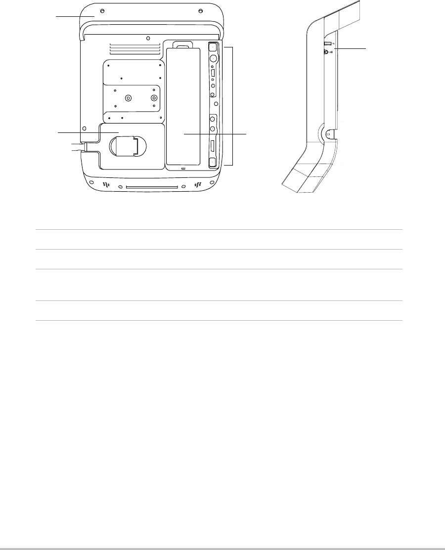
Compartments and connectors
Thebackofthesystemhascompartmentsforthebatteryandtransduceraswellasconnectors
forUSBdevices,powercords,cables,andmore.Thesidehasadditionalconnectors.
2
Figure 1.1 System Back (Left) and Side (Right):
1Handle
2Transducer
3 Connectors
(See the table “Connectivity Symbols on Back and Side of System”)
4 Battery compartment
4
3
2
1
3
Chapter 1: Getting Started 3
Getting Started
Each connector on the back and side of the system has a symbol that describes its use.
Installing or removing the battery
To install the battery
1Disconnectthepowersupplyfromtheultrasoundsystem.
2Slidethetwoprongsatthebottomofthebatteryintothebatterycompartmentontheback
ofthesystem.
3Lowerthebatteryintothecompartment.
4Pushdownonthelockingleveratthetopofthebatterytosecurethebattery.
To remove the battery
1Disconnectthepowersupplyfromtheultrasoundsystem.
2Pushdownonthelockingleveratthetopofthebattery,andliftthebatteryup.
Using AC power and charging the battery
ThebatterychargeswhenthesystemisconnectedtotheACpowersupply.Afullydischarged
batteryrechargesinlessthanfivehours.
ThesystemcanrunonACpowerandchargethebatteryifACpowerisconnectedtothe
system.
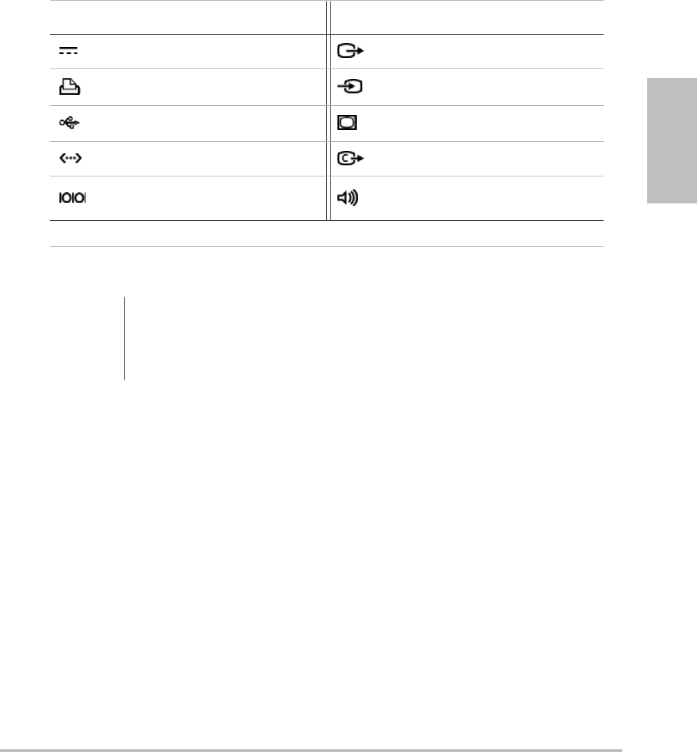
Connectivity Symbols on Back and Side of System
Symbol Definition Symbol Definition
DC input S-video out
Print control S-video in
USB DVI video out
Ethernet* Composite video out
RS-232 (DVD recorder
or bar code scanner) Audio out
* Not currently supported
WARNING: To avoid injury to the operator and to prevent damage to the ultrasound system,
inspect the battery for leaks prior to installing.
To avoid data loss and to conduct a safe system shutdown, always keep a battery in
the system.

4
Thesystemcanrunonbatterypowerforuptotwohours,dependingontheimagingmodeand
thedisplaybrightness.
To operate the system using AC power
1ConnecttheDCpowercablefromthepowersupplytotheconnectoronthesystem.See
Figure 1.1onpage 2.
2ConnecttheACpowercordtothepowersupplyandtoahospital‐gradeelectricaloutlet.
Turning the system on or off
To turn the system on or off
Pressthepowerswitch.(See“Systemcontrols”onpage 7.)
To wake up the system
Toconservebatterylifewhilethesystemison,thesystemgoesintosleepmodeifuntouched
forapresettime.Toadjustthetimeforsleepdelay,see“A u d i o , Batterysetup”onpage 18.
Pressakey,ortouchthetouchpad.
WARNING: The equipment shall be connected to a center-tapped single phase supply circuit
when users in the United States connect the equipment to a 240V supply system.
Caution: Verify that the hospital supply voltage corresponds to the power supply voltage
range. See “Electrical” on page 87.
Caution: Do not use the system if an error message appears on the display. Note the error
code and turn off the system. Call SonoSite or your local representative.
Chapter 1: Getting Started 5
Getting Started
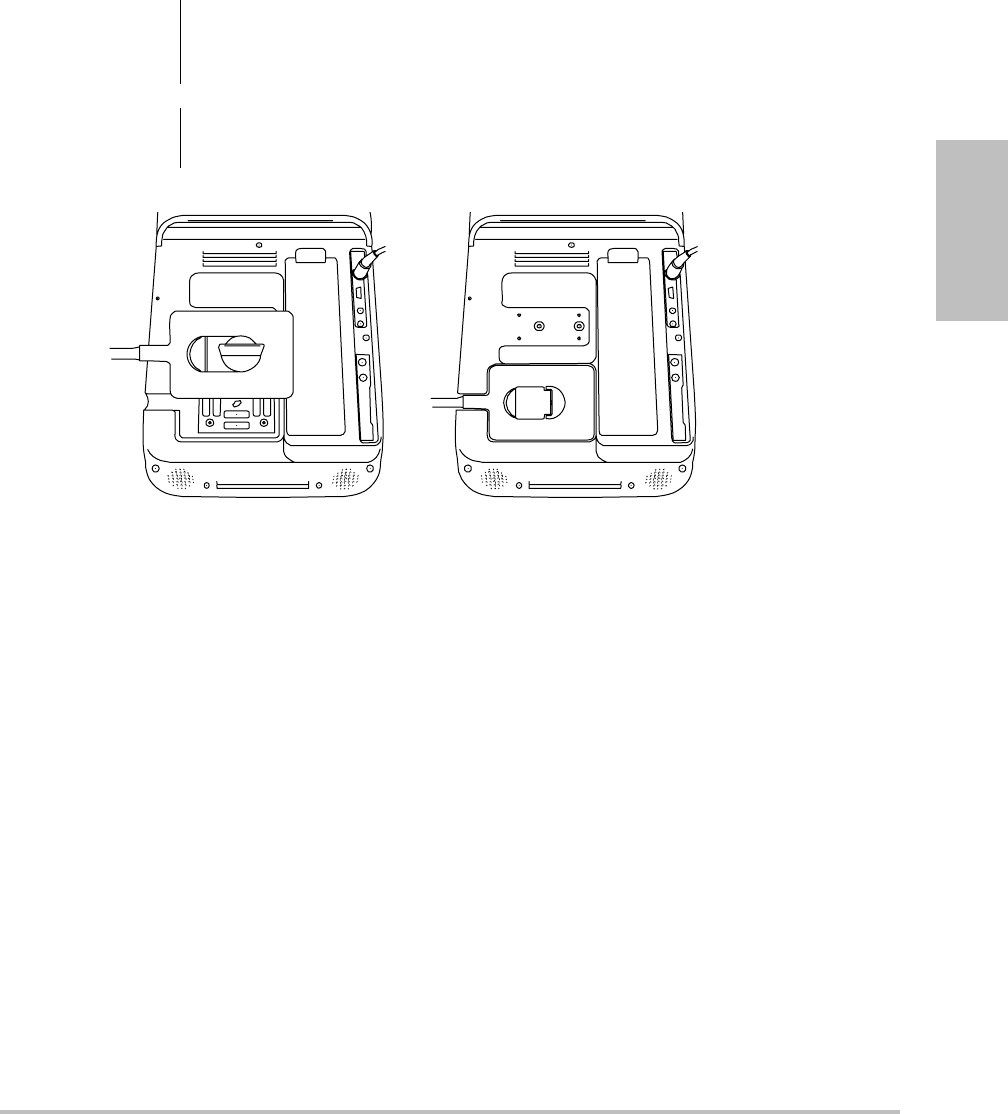
Connecting transducers
Figure 1.2 Connect the Transducer
To connect a transducer
1Pullthetransducerlatchup,androtateitclockwise.
2Alignthetransducerconnectorwiththeconnectoronthebackofthesystem.
3Insertthetransducerconnectorintothesystemconnector.
4Turnthelatchcounterclockwise.
5Pressthelatchdown,securingthetransducerconnectortothesystem.
To remove a transducer
1Pullthetransducerlatchup,androtateitclockwise.
2Pullthetransducerconnectorawayfromthesystem.
WARNING: To avoid injury to the patient, do not place the connector on the patient. Operate
the ultrasound system in the S Stand or on a convenient surface to allow air flow
past the connector.
Caution: To avoid damaging the transducer connector, do not allow foreign material in the
connector.

6
Inserting and removing USB storage devices
Imagesandclipsaresavedtointernalstorageandareorganizedinasortablepatientlist.You
canarchivetheimagesandclipsfromtheultrasoundsystemtoaPCusingaUSBstorage
device.AlthoughtheimagesandclipscannotbeviewedfromaUSBstoragedeviceonthe
ultrasoundsystem,youcanremovethedeviceandviewthemonyourPC.
YoucanalsoimportandexportuseraccountsandtheeventlogusingaUSBstoragedevice.
TherearethreeUSBportsonthesystem:twoontheback,andoneontheside.Foradditional
USBports,youcanconnectaUSBhubintoanyUSBport.
To insert a USB storage device
InserttheUSBstoragedeviceintoaUSBportonthesystem.SeeFigure 1.1onpage 2.
TheUSBstoragedeviceisreadywhentheUSBiconappears.
Toviewinformationaboutthedevice,see“USBDevicessetup”onpage 20.
To remove a USB storage device
RemovingtheUSBstoragedevicewhilethesystemisexportingmaycausetheexportedfiles
tobecorruptedorincomplete.
1WaitfivesecondsaftertheUSBanimationstops.
2RemovetheUSBstoragedevicefromtheport.
WARNING: To avoid damaging the USB storage device and losing patient data from it, observe
the following:
• Do not remove the USB storage device or turn off the ultrasound system while the
system is exporting.
• Do not bump or otherwise apply pressure to the USB storage device while it is in a
USB port on the ultrasound system. The connector could break.
Caution: If the USB icon does not appear in the system status area on-screen, the USB storage
device may be defective or password-protected. Turn the system off and replace the
device.
Chapter 1: Getting Started 7
Getting Started
System controls
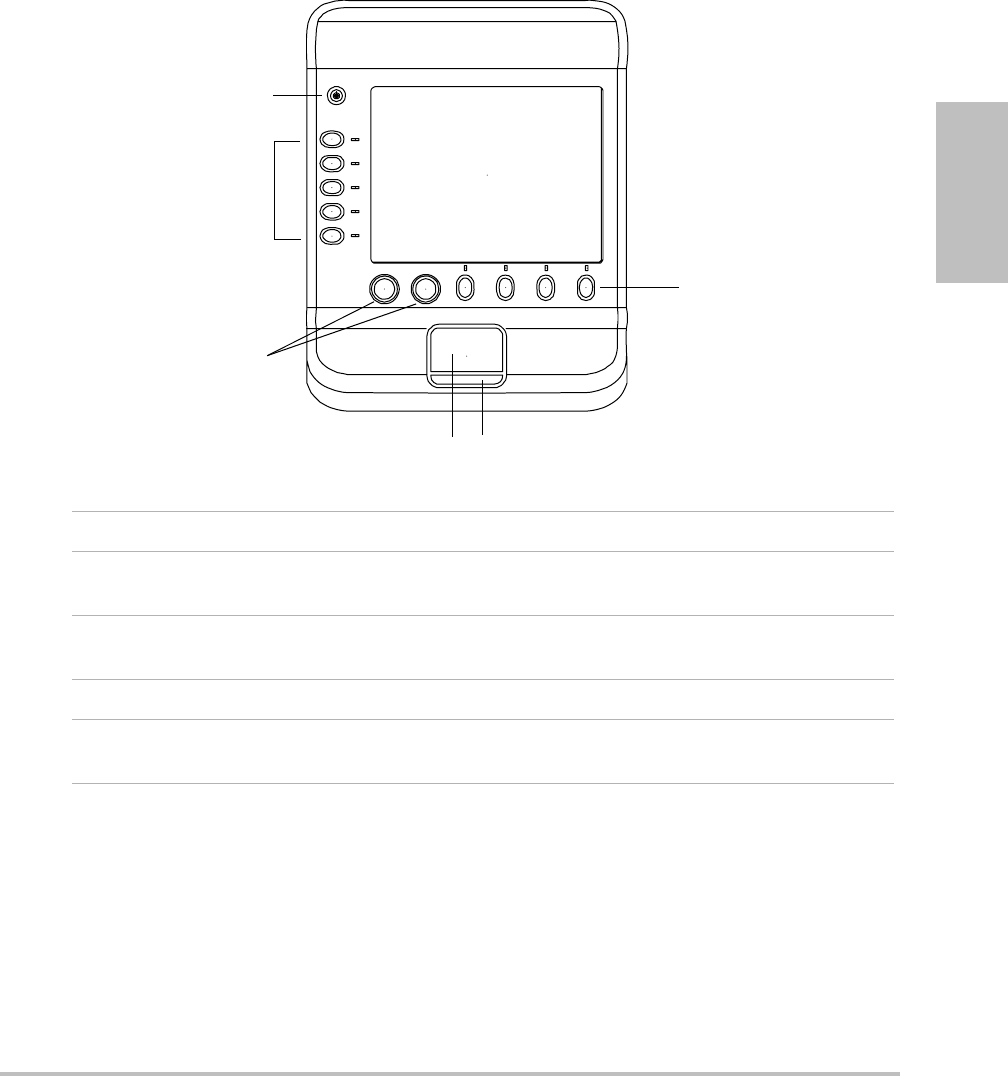
Figure 1.3 System Controls:
2
3
2
45
1
1 Power switch Turns the system on and off.
2 Control keys Perform an action or make a selection based on context.
Current names appear on-screen adjacent to the keys.
3 Control knobs Adjust gain, depth, cine buffer, ROI box, and brightness.
Sometimes perform an action. Are turned or pressed.
4 Touchpad Moves the pointer and other items.
5Touchpad key Works in conjunction with the touchpad. Is pressed to
activate an item on-screen.
8
Screen layout
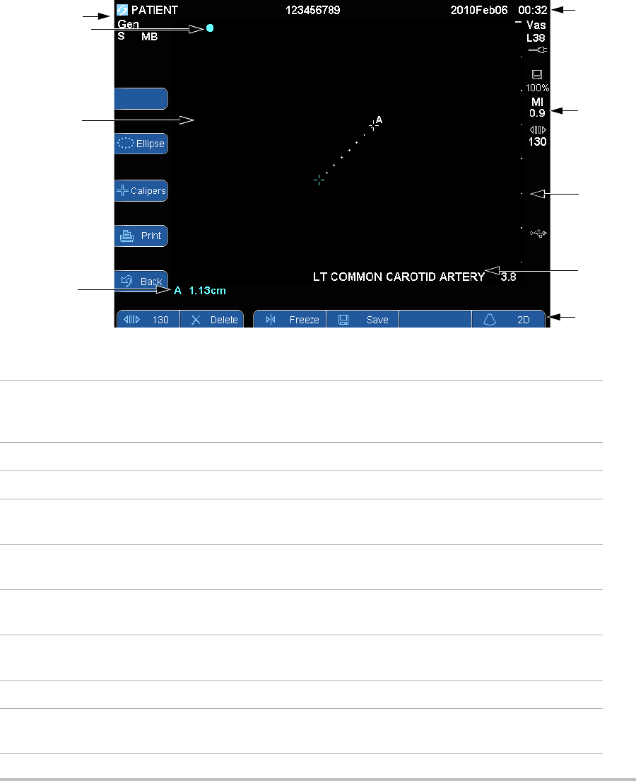
Figure 1.4 Screen Layout
3
7
6
5
4
1
8
2
9
1 Mode Data Area Current imaging mode information (for example, Gen, S, THI). S
and THI are on when available on the transducer and are not
user-controlled. For definitions, see “Glossary.”
2 Orientation Marker Provides indication for image orientation.
3 Image Ultrasound image.
4Measurement Data
Area
Current data on measurements.
5 Patient Header Includes current patient name, patient ID number, institution,
user, and date/time.
6 System Status Information on system status (for example, exam type,
transducer, AC connected, battery charging, and USB).
7 Depth Marker Marks in .5 cm, 1 cm, and 5 cm increments depending on depth.
To specify style, see “Presets setup” on page 19.
8 Exam label Preset exam label from patient information form.
9 Control keys Controls available in the current context. (See also “Control keys”
on page 9.)
Chapter 1: Getting Started 9
Getting Started
General interaction
Touchpad
Informsandthesetuppages,thetouchpadissimilartoamouseonportablePCs.Usingthe
touchpad,youmovethepointertoanitemandthenclick(pressthekeybelowthetouchpad)
toactivatethatitem.
Inothercontexts,thetouchpadadjustsandmovesitemson‐screen:calipers,regionofinterest
(ROI)box,andmore.
Control keys
Thecontrolkeysdisplayforms,adjustsettings,andperformactionssuchasfreezingand
zooming.Thefunctionalitydependsoncontext.Thecurrentnameappearson‐screennexttothe
key.Controlkeysareusuallypressed,butinformsyoucanalsoclickthem.ThePage x/x
controlkeydisplaysadditionalcontrolkeys.
Acontrolkeyfunctionsinoneofthefollowingways:
Cycle Movesthroughalistofsettings.
On-Off Turnsafeatureonoroff.
Action Performsanactionsuchassavingaclip.
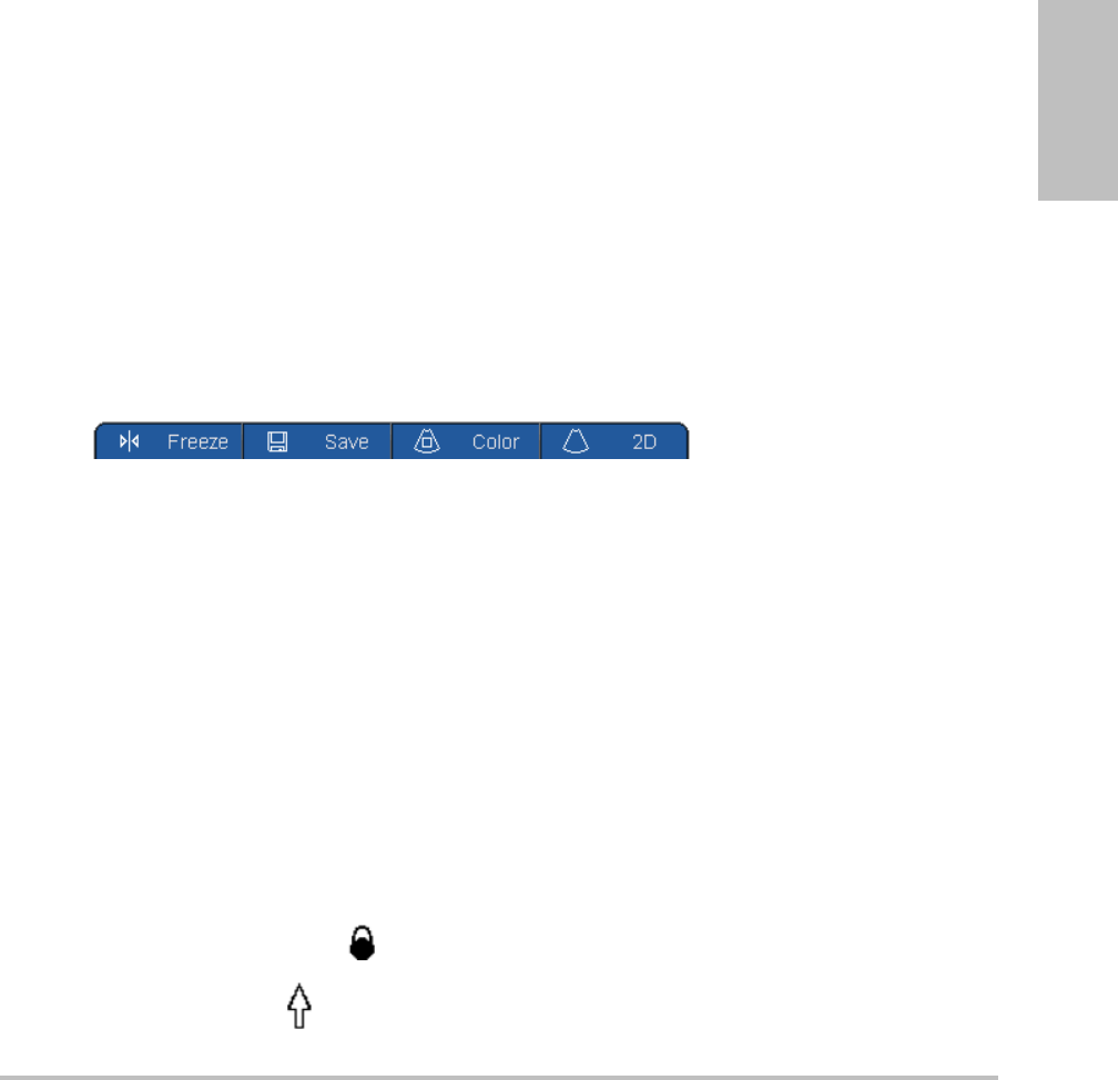
Figure 1.5 Control key names, lower screen (Color imaging shown)
Entering text
Informs,youcanentertextintextfieldsusingeithertheon‐screenkeyboardoranexternalUSB
keyboardconnectedtoaUSBportonthesystem.
To enter text in text fields
1Clickatextfield.
Theon‐screenkeyboardappearswiththetextfieldatthetop.
2Clickeachcharacteryouwanttoenter.Ifanexternalkeyboardisconnected,youcanenter
charactersbytyping.
•TheÄñkeydisplaysandhidesinternationalcharacters.
•TheSYMBOLSkeydisplayssymbolsandpunctuation.
•TheCAPSLOCKkeyturnscapitallettersonandoff.
•TheSHIFTkeyturnscapitallettersonoroffforthenextletterentered.

10
•TheDELETEkeydeletesthecharacterrightofthepointer.
3(Optional)Navigateamongtextfields:
•ClickNexttoadvancetothenextfield.
•ClickPrevtoreturntothepreviousfield.
4Toexitthekeyboard,clickoneofthefollowing:
•OKtosavechanges.
•2Dtosavechangesanddisplay2Dimaging.
Preparing transducers
Acousticcouplinggelmustbeusedduringexams.Althoughmostgelsprovidesuitable
acousticcoupling,somegelsareincompatiblewithsometransducermaterials.SonoSite
recommendsAquasonic®gelandprovidesasamplewiththesystem.
Forgeneraluse,applyaliberalamountofgelbetweenthetransducerandthebody.For
invasiveorsurgicaluse,installatransducersheath.
WARNING: Some transducer sheaths contain natural rubber latex and talc, which can cause
allergic reactions in some individuals. Refer to 21 CFR 801.437, User labeling for
devices that contain natural rubber.
Some gels and sterilants can cause an allergic reaction on some individuals.
Caution: To avoid damage to the transducer, use only gels recommended by SonoSite.
Using gels other than the one recommended by SonoSite can damage the
transducer and void the warranty. If you have questions about gel compatibility,
contact SonoSite or your local representative.
SonoSite recommends that you clean transducers after each use. See “Cleaning
and disinfecting transducers” on page 41.
WARNING: To prevent contamination, the use of sterile transducer sheaths and sterile
coupling gel is recommended for clinical applications of an invasive or surgical
nature. Do not apply the transducer sheath and gel until you are ready to
perform the procedure.

Chapter 1: Getting Started 11
Getting Started
To install a transducer sheath
SonoSiterecommendstheuseofmarket‐cleared,transducersheathsforintracavitaryor
surgicalapplications.Tolessentheriskofcontamination,installthesheathonlywhenyouare
readytoperformtheprocedure.
1Placegelinsidethesheath.
2Insertthetransducerintothesheath.
3Pullthesheathoverthetransducerandcableuntilthesheathisfullyextended.
4Securethesheathusingthebandssuppliedwiththesheath.
5Checkforandeliminatebubblesbetweenthefaceofthetransducerandthesheath.
Bubblesbetweenthefaceofthetransducerandthesheathmayaffecttheultrasoundimage.
6Inspectthesheathtoensurethattherearenoholesortears.
Intended uses
Theintendedusesforeachexamtypeareasfollows.Fortheintendedtransducerforeachexam
type,see“Imagingmodesandexamsavailablebytransducer”onpage 24.
Abdominal Imaging Applications Thissystemtransmitsultrasoundenergyintotheabdomen
ofpatientsusing2D,SonoMB™technology,colorDoppler(Color),colorpowerDoppler
(CPD),andTissueHarmonicImaging(THI)toobtainultrasoundimages.Theliver,kidneys,
pancreas,spleen,gallbladder,bileducts,transplantedorgans,abdominalvessels,and
surroundinganatomicalstructurescanbeassessedforthepresenceorabsenceofpathology
transabdominally.
Cardiac Imaging Applications Thissystemtransmitsultrasoundenergyintothethoraxof
patientsusing2D,SonoMBtechnology,colorDoppler(Color),andTissueHarmonicImaging
(THI),toobtainultrasoundimages.Theheart,cardiacvalves,greatvessels,surrounding
anatomicalstructures,overallcardiacperformance,andheartsizecanbeassessedforthe
presenceorabsenceofpathology.
Gynecology and Infertility Imaging Applications Thissystemtransmitsultrasoundenergyin
thepelvisandlowerabdomenusing2D,SonoMBtechnology,colorpowerDoppler(CPD),and
colorDoppler(Color)toobtainultrasoundimages.Theuterus,ovaries,adnexa,and
surroundinganatomicalstructurescanbeassessedforthepresenceorabsenceofpathology
transabdominallyortransvaginally.
Interventional Imaging Applications Thissystemtransmitsultrasoundenergyintothevarious
partsofthebodyusing2D,SonoMBtechnology,colorDoppler(Color),colorpowerDoppler
(CPD),andTissueHarmonicImaging(THI)toobtainultrasoundimagesthatprovideguidance
duringinterventionalprocedures.Thissystemcanbeusedtoprovideultrasoundguidancefor
biopsyanddrainageprocedures,vascularlineplacement,peripheralnerveblocks,spinalnerve
blocksandtaps,amniocentesisandotherobstetricalprocedures,andprovideassistanceduring
abdominal,breast,andneurologicalsurgery.

12
Obstetrical Imaging Applications Thissystemtransmitsultrasoundenergyintothepelvisof
pregnantwomenusing2D,SonoMBtechnology,colorDoppler(Color),andcolorpower
Doppler(CPD)toobtainultrasoundimages.Thefetalanatomy,amnioticfluid,and
surroundinganatomicalstructurescanbeassessedforthepresenceorabsenceofpathology
transvaginally.CPDandcolorDoppler(Color)imagingisintendedforhigh‐riskpregnant
women.
Pediatric Imaging Applications Thissystemtransmitsultrasoundenergyintothepediatric
patientsusing2D,SonoMBmulti‐beamtechnology,colorDoppler(Color),andcolorpower
Doppler(CPD)toobtainultrasoundimages.Thepediatricabdominalandpelvicanatomy,
pediatrichips,andsurroundinganatomicalstructurescanbeassessedforthepresenceor
absenceofpathology.
Superficial Imaging Applications Thissystemtransmitsultrasoundenergyintovariousparts
ofthebodyusing2D,SonoMBmulti‐beamtechnology,colorDoppler(Color),andcolorpower
Doppler(CPD)toobtainultrasoundimages.Thebreast,thyroid,testicle,lymphnodes,hernias,
musculoskeletalstructures,softtissuestructures,andsurroundinganatomicalstructurescan
beassessedforthepresenceorabsenceofpathology.Thissystemcanbeusedtoprovide
ultrasoundguidanceforbiopsyanddrainageprocedures,vascularlineplacement,peripheral
nerveblocks,andspinalnerveblocksandtaps.
Vascular Imaging Applications Thissystemtransmitsultrasoundenergyintothevariousparts
ofthebodyusing2D,SonoMB,colorDoppler(Color),andcolorpowerDoppler(CPD)to
obtainultrasoundimages.Thecarotidarteries,deepveins,andarteriesinthearmsandlegs,
superficialveinsinthearmsandlegs,greatvesselsintheabdomen,andvarioussmallvessels
feedingorganscanbeassessedforthepresenceorabsenceofpathology.
WARNING: To prevent injury or misdiagnosis do not use this system for Percutaneous Umbilical
Blood Sampling (PUBS) or in vitro Fertilization (IVF) The system has not been
validated to be proven effective for these two uses.
CPD or Color images can be used as an adjunctive method, not as a screening tool,
for the detection of structural anomalies of the fetal heart and as an adjunctive
method, not as a screening tool for the diagnosis of Intrauterine Growth Retardation
(IUGR).

Chapter 2: System Setup 13
System Setup
Chapter 2: System Setup
Thesetuppagesletyoucustomizethesystemandsetpreferences.
Displaying the setup pages
To display a setup page
1In2Dimagingmode,dooneofthefollowing:
•PressPatient,andthenpressSetuponthehorizontalrowofcontrolkeys.
•PressSetupontheverticalrowofcontrolkeys.
2ClickthesetuppageunderSetup Pages.
Toreturntoimagingfromasetuppage,pressDone.
Restoring default settings
To restore default settings for a setup page
Onthesetuppage,press Reset.
To restore all default settings
1Turnthesystemoff.
2ConnectthesystemtoACpower.(See“TooperatethesystemusingACpower”on
page 4.)
3Simultaneouslypressthepowerkeyandthecontrolkeybelowit(theupper‐leftcontrol
key).
Thesystembeepsseveraltimes.

14
Administration setup
OntheAdministrationsetuppage,youcanconfigurethesystemtorequireuserstologin
andenterpasswords.Requiredloginhelpsprotectpatientdata.Youcanalsoaddand
deleteusers,changepasswords,importandexportuseraccounts,andviewtheeventlog.
Security settings
Securitysettingsonthesystemallowyoutomeettheapplicablesecurityrequirements
listedintheHIPAAstandard.Usersareultimatelyresponsibleforensuringthesecurity
andprotectionofallelectronicprotectedhealthinformationcollected,stored,reviewed,
andtransmittedonthesystem.
To log in as Administrator
1OntheAdministrationsetuppage,typeAdministratorintheNamebox.(See“Entering
text”onpage 9.)
2TypetheadministratorpasswordinthePasswordbox.
Ifyoudon’thavetheadministratorpassword,contactSonoSite.(See“SonoSiteTechnical
Support”onpage viii.)
3ClickLogin.
To log out as Administrator
Turnofforrestartthesystem.
To require user login
YoucansetthesystemtodisplaytheUserLoginscreenatstartup.
1LoginasAdministrator.
2IntheUser Loginlist,clickOn.
•Onrequiresausernameandpasswordatstartup.
•Offallowsaccesstothesystemwithoutausernameandpassword.
WARNING: Health care providers who maintain or transmit health information are required
by the Health Insurance Portability and Accountability Act (HIPAA) of 1996 and
the European Union Data Protection Directive (95/46/EC) to implement
appropriate procedures: to ensure the integrity and confidentiality of
information; to protect against any reasonably anticipated threats or hazards to
the security or integrity of the information or unauthorized uses or disclosures
of the information.

Chapter 2: System Setup 15
System Setup
To change the administrator password or let users change passwords
1LoginasAdministrator.
2UnderUser List,clickAdministrator.
3Doanyofthefollowing:
• Changetheadministratorpassword:UnderUser Information,typethenew
passwordinthePasswordboxandConfirmbox.(See“Choosingasecurepassword”
onpage 17.)
•Letuserschangetheirpasswords:SelectthePassword changescheckbox.
4ClickSave.
User setup
To add a new user
1LoginasAdministrator.
2ClickNew.
3UnderUser Information,fillintheName,Password,andConfirmboxes.(See“Choosing
asecurepassword”onpage 17.)
4(Optional)IntheUser box,typetheuser’sinitialstodisplaytheminthepatientheader
andtheUserboxinthepatientinformationform.
5(Optional)SelecttheAdministration Accesscheckboxtoallowaccesstoall
administrationprivileges.
6ClickSave.
To modify user information
1LoginasAdministrator.
2UnderUser List,clicktheuser.
3UnderUser Information,makechangesasdesired.
4ClickSave.
Anychangetotheusernamereplacesthepreviousname.
To delete a user
1LoginasAdministrator.
2UnderUser List,clicktheuser.
3ClickDelete.
4Click Yes.

16
To change a user password
1LoginasAdministrator.
2IntheUser List,clicktheuser.
3TypethenewpasswordinthePasswordboxandConfirmbox.
4ClickSave.
Exporting or importing user accounts
Theexportandimportcommandsletyouconfiguremultiplesystemsandbackupuser
accountinformation.
To export user accounts
1InsertaUSBstoragedevice.
2LoginasAdministrator.
3PressExport.AlistofUSBdevicesappears.
4ClicktheUSBstoragedevice,andclickExport.
AllusernamesandpasswordsarecopiedtotheUSBstoragedevice.
To import user accounts
1InserttheUSBstoragedevicethatcontainstheaccounts.
2LoginasAdministrator.
3PressImport.
4ClicktheUSBstoragedevice,andclickImport.
5ClickDoneinthedialogboxthatappears.
Thesystemrestarts.Allusernamesandpasswordsonthesystemarereplacedwiththe
importeddata.
Exporting and clearing the Event log
TheEventlogcollectserrorsandeventsandcanbeexportedtoaUSBstoragedeviceand
readonaPC.
To view the Event log
1LoginasAdministrator.
2PressLog.
TheEventlogappears.
Toreturntothepreviousscreen,pressBack.

Chapter 2: System Setup 17
System Setup
To export the Event log
TheEventloghasthefilename(log.txt).ExportingtheEventlogtoaUSBstoragedevice
overwritesanyexistinglog.txtfile.
1InsertaUSBstoragedevice.
2PressLogandthenpressExport.
AlistofUSBdevicesappears.
3ClicktheUSBstoragedevice,andclickExport.
TheEventlogisatextfilethatyoucanopeninatext‐editingapplication(forexample,
MicrosoftWordorNotepad).
To clear the Event log
1ViewtheEventlog.
2PressClear.
3ClickYes.
Logging in as user
Ifuserloginisrequired,theUserLoginscreenappearswhenyouturnonthesystem.(See
“Torequireuserlogin”onpage 14.)
To log in as user
1Turnonthesystem.
2IntheUser Loginscreen,typeyournameandpassword,andclickOK.
To log in as guest
Guestscanscanbutcan’taccesssystemsetupandpatientinformation.
1Turnonthesystem.
2IntheUser Loginscreen,clickGuest.
To change your password
1Turnonthesystem.
2IntheUser Loginscreen,clickPassword.
3Typeyouroldandnewpasswords,confirmthenewpassword,andthenclickOK.
Choosing a secure password
Toensuresecurity,chooseapasswordthatcontainsuppercasecharacters(A‐Z),lowercase
characters(a‐z),andnumbers(0‐9).Passwordsarecase‐sensitive.

18
Audio, Battery setup
OntheAudio,Batterysetuppage,youcanselectoptionsfromthefollowinglists:
Key click:ClickOnorOffforkeystomakeaclickingsoundwhenpressed.
Beep alert: ClickOnorOffforthesystemtobeepwhensaving,warning,starting,or
shuttingdown.
Sleep delay:ClickOff,or5or10minutestospecifytheperiodofinactivitybeforethe
systemgoesintosleepmode.
Power delay:ClickOff,or15or30minutestospecifytheperiodofinactivitybeforethe
systemautomaticallyturnsoff.
Connectivity setup
OntheConnectivitysetuppage,youselectoptionsforusingdevicesandforalertswhen
internalstorageisfull.
To configure the system for a printer
1Setuptheprinterhardware.(SeeinstructionsincludedwiththeprinterorSSeries
stand.)
2OntheConnectivitysetuppage,clicktheprinterinthePrinterlist.
To configure the system for a DVD recorder or bar code scanner
1OntheConnectivitysetuppage,dothefollowing:
•(DVDrecorder)IntheVideo Modelist,clickthevideostandard:NTSCorPAL.
•IntheSerial Portlist,clicktheperipheral.
2ClickYestorestartthesystem.
3Attachaserialcable(RS‐232)fromtheserialportonthebackofthesystemtothe
peripheral.
To receive storage alerts
OntheConnectivitysetuppage,selectInternal Storage Capacity Alert.
Thesystemdisplaysamessageifinternalstorageisnearcapacitywhenyouendan
exam.

Chapter 2: System Setup 19
System Setup
Date and Time setup
To set the date and time
OntheDateandTimesetuppage,dothefollowing:
•IntheDate box,typethecurrentdate.(See“Enteringtext”onpage 9.)
•IntheTime box,typethecurrenttimein24 hourformat(hoursandminutes).
Display Information setup
OntheDisplayInformationsetuppage,youcanspecifywhichdetailsappearon‐screen
duringimaging.Youcanselectcheckboxesinthefollowingsections:
Patient Header: Informationfromthepatientinformationform.(See“Patient
informationform”onpage 27.)
Mode Data:Imaginginformation.
System Status:Power,battery,printer,andsimilarinformation.
Presets setup
ThePresetssetuppagehassettingsforgeneralpreferences.Youcanselectfromthe
followinglists:
Depth Markers:Type 1displaysunnumberedmarkers,withthemaximumdepth
numberinthelowerrightscreen.Type 2displaysmarkerswithnumbers.
Thermal Index:YoucanselectTIS,TIB,orTIC.Thedefaultsettingisbasedonexamtype:
OBisTIB,TCDisTIC,andallothersareTIS.
Clip Length: Cliplengthinseconds.
Language:Thesystemlanguage.Changingthelanguagerequiresrestartingthesystem.
Display Brightness:Highdisplaysbrighterkeynamesandiconsandissuitablefora
brightenvironment,suchasdaylight.Lowdisplaysdimmerkeynamesandiconsandis
suitableforadarkenvironment.
Auto save Pat. Form:Automaticallysavesthepatientinformationformasanimagein
thepatient’sfile.

20
System Information setup
TheSystemInformationsetuppagedisplayssystemhardwareandsoftwareversions,and
licenseinformation.
Seealso“Toenteralicensekey”onpage 38.
USB Devices setup
OntheUSBDevicessetuppage,youcanviewinformationaboutconnectedUSBdevices,
includingspaceavailability.Youcanalsospecifyafileformatforimagesyouexporttoa
USBstoragedevice.
To specify a file format for exported images
Theimageformatyouspecifyaffectsonlystillimages.ClipsexportinH.264videosaved
asMP4files.Toviewthem,SonoSiterecommendsQuickTime7.0orlater.
1OntheUSBDevicessetuppage,clickExport.
2UnderSiteLink,selectanimageformat.ForJPEGimageformat,alsoselectaJPEG
compression.
Ahighcompressionhasasmallerfilesizebutlessdetail.
3ClickasortorderunderSort By.
Thesortorderspecifieshowexportedfilesareorganized.
Toreturntothepreviousscreen,clickDevices.

Chapter 3: Imaging 21
Imaging
Chapter 3: Imaging
Imaging modes
Thesystemhasahigh‐performanceLCDandadvancedimage‐optimizationtechnologythat
greatlysimplifiesusercontrols.Imagingmodesavailabledependonthetransducerandexam
type.See“Imagingmodesandexamsavailablebytransducer”onpage 24.
2D imaging
2Disthesystemʹsdefaultimagingmode.Thesystemdisplaysechoesintwodimensionsby
assigningabrightnesslevelbasedontheechosignalamplitude.Toachievethebestpossible
imagequality,properlyadjustthedisplaybrightness,gain,depthsettings,viewingangle,and
examtype.Also,useanoptimizationsettingthatbestmatchesyourneeds.
To display the 2D image
1Doanyofthefollowing:
•Turnonthesystem.
•Press2D.
2Adjustsettings.See“2Dsettings.”
2D settings
In2Dimaging,thefollowingcontrolkeysadjustsettings.Seealso“A d j u s t i n g depthandgain”
onpage 23.
2D settings
Control key Icon Description
Auto Gain The gain adjusts each time you press the key. To adjust gain
manually, see “Adjusting depth and gain” on page 23.
Brightness Adjusts the display brightness. Press Bright and then turn the
left-hand knob. Settings range from 1 to 10. (You can also adjust
the brightness of only the key names and icons. See “Presets
setup” on page 19.)
The display brightness affects battery life. To conserve battery life,
adjust brightness to a lower setting.
22
CPD and color Doppler imaging
ColorpowerDoppler(CPD)andcolorDoppler(Color)areoptionalfeatures.
CPDisusedtovisualizethepresenceofdetectablebloodflow.Colorisusedtovisualizethe
presence,velocity,anddirectionofbloodflowinawiderangeofflowstates.
To display the CPD or Color image
1PressColor.
AROIboxappearsinthecenterofthe2Dimage.
2PressCPDorColorontheleft.
InColorimaging,theColorindicatorbarontheupperleft‐handscreendisplaysvelocityin
cm/s.
3Usingthetouchpad,positiontheROIboxasneeded.
Agreenoutlineshowsthechange.
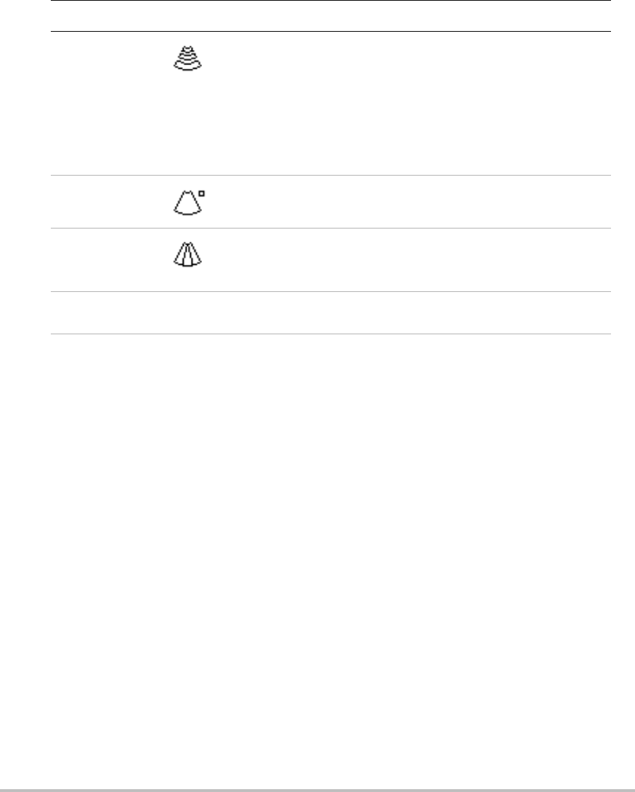
Optimize Settings are as follows:
•Res provides the best possible resolution.
•Gen provides a balance between resolution and penetration.
•Pen provides the best possible penetration.
Some of the parameters optimized to provide the best image
include focal zones, aperture size, frequency (center and
bandwidth), and waveform. They cannot be adjusted by the user.
Orientation Select from four image orientations: U/R (Up/Right), U/L (Up/Left),
D/L (Down/Left), D/R (Down/Right).
SonoMB (MB) MB On and MB Off turn SonoMB technology on and off. When
SonoMB is on, MB appears in the upper left-hand screen.
SonoMB depends on transducer and exam type.
Page x/x Indicates which page of options is displayed. Press to display the
next page.
2D settings (Continued)
Control key Icon Description

Chapter 3: Imaging 23
Imaging
Adjusting depth and gain
To adjust depth
Youcanadjustthedepthinallimagingmodes.Theverticaldepthscaleismarkedin0.5 cm,
1cm,and5cmincrements,dependingonthedepth.Tochangethestyleofdepthmarkers,see
“Presetssetup”onpage 19.
TurntheDepthknob:
•Rightincreasesthedisplayeddepth.
•Leftdecreasesthedisplayeddepth.
To adjust gain manually
Toadjustgainautomaticallyin2D,see“2Dsettings”onpage 21.
1Presstheleft‐handknobtoselectasetting:
•Nearadjuststhegainappliedtothenearfieldoftheimage.
•Faradjuststhegainappliedtothefarfieldoftheimage.
•Gain adjuststheoverallgainappliedtotheentireimage.
InCPDorColorimaging,theOverallsettingaffectsthecolorgainappliedtotheregionof
interest(ROI)box.TheNearandFarsettingsaffectonlythe2Dimage.(Nearandfar
correspondtothetimegaincompensation[TGC]controlsonotherultrasoundsystems.)
2Turntheknob.
Freezing, viewing frames, and zooming
To freeze or unfreeze an image
PressFreeze.
Onafrozenimage,thecineiconandframenumberappearinthesystemstatusarea.
To move forward or backward in the cine buffer
Onafrozenimage,turnthecineknob.
Thetotalnumberofframesappearsnexttothecineicon.Thenumberchangestothecurrent
framenumberasyoumoveforwardorbackward.

24
To zoom in on an image
Youcanfreezeorunfreezetheimageorchangetheimagingmodeatanytimewhilezooming.
1PressZoom.AROIboxappears.
2Usingthetouchpad,positiontheROIboxasdesired.
3PressZoomagain.
TheimageintheROIboxismagnifiedby100%.
4(Optional)Iftheimageisfrozen,usethetouchpadtopantheimageup,down,left,andright.
Toexitzoom,pressZoomagain.
Turning guidelines on and off
Guidelinesareforneedleguidanceandareanoptionalfeature.
To turn guidelines on or off
Ona2Dimage,pressoneofthefollowingcontrolkeys:
•Biopsy: Thisfeaturedependsontransducertype.Formoreinformation,seeSonoSite
BiopsyUserGuide.
•Guide: Thisfeaturedependsontransducerandexamtype.Formoreinformation,see
SonoSiteBracketandNeedleGuideUserGuide.
Imaging modes and exams available by transducer
Thetransduceryouusedetermineswhichexamtypesareavailable.Inaddition,theexamtype
youselectdetermineswhichimagingmodesareavailable.
To change the exam type
Dooneofthefollowing:
•In2Dimaging,pressExam,andthenclicktheexamtypeinthemenu.
•Onthepatientinformationform,clicktheexamtypeintheExamlist.(See“Patient
informationform”onpage 27.)
WARNING: To prevent misdiagnosis or harm to the patient, understand your system’s
capabilities prior to use. The diagnostic capability differs for each transducer,
exam type, and imaging mode. In addition, transducers have been developed to
specific criteria depending on their physical application. These criteria include
biocompatability requirements.

Chapter 3: Imaging 25
Imaging
Imaging modes and exams available by transducer
Imaging Mode
Transducer Exam
Type1
S Series
System 2D2CPD Color
C11x Nrv S-Nerve X X X
Vas S-Nerve X X X
C60x Abd S-Cath
S-FAST
S-ICU
XXX
Nrv S-Nerve X X X
HFL38x Bre S-Cath X X X
Nrv S-Nerve X X X
SmP S-Cath
S-FAST
S-ICU
XXX
Vas S-Cath
S-FAST
S-ICU
S-Nerve
XXX
Ven S-Cath
S-FAST
S-ICU
XXX
ICTx Gyn S-FAST X X X
OB S-FAST X X X

26
L25x Nrv S-Nerve X X X
Sup S-Cath X X X
Vas S-Cath
S-ICU
S-Nerve
XXX
Ven S-Cath
S-ICU
XXX
L38x Bre S-Cath X X X
Nrv S-Nerve X X X
SmP S-Cath
S-FAST
S-ICU
XXX
Vas S-Cath
S-FAST
S-ICU
S-Nerve
XXX
Ven S-Cath
S-FAST
S-ICU
XXX
P21x Abd S-Cath
S-FAST
S-ICU
XXX
Crd S-FAST
S-ICU
X—X
1. Exam type abbreviations are as follows: Abd = Abdomen, Bre = Breast,
Crd = Cardiac, Nrv = Nerve, OB = Obstetrical, SmP = Small Parts, Sup =
Superficial, Vas = Vascular, Ven = Venous.
2. The optimization settings for 2D are Res, Gen, and Pen.
Imaging modes and exams available by transducer (Continued)
Imaging Mode
Transducer Exam
Type1
S Series
System 2D2CPD Color

Chapter 3: Imaging 27
Imaging
Patient information form
Thepatientinformationformletsyouenterpatientidentification,exam,andclinical
informationforthepatientexam.
Whenyoucreateanewpatientinformationform,allimagesandotherdatayousaveduring
theexamarelinkedtothatpatient.(See“Savingimagesandclips”onpage 28.)
To create a new patient information form
1In2D,pressPatient.
2PressNew.
3Fillintheformfields.See“Patientinformationformfields”onpage 28and“Enteringtext”
onpage 9.
4PressDone.
To edit a patient information form
Youcaneditpatientinformationduringtheexam.However,ifyouchangethepatientnameor
IDaftersavinganimage,anewpatientinformationformiscreated.
1In2D,pressPatient.
2IfyouneedtochangethepatientnameorID,saveanydatayouwanttokeep.
3Makechangesasdesired.
4Pressoneofthefollowing:
•Canceltoundochangesandreturntoimaging.
•Donetosavechangesandreturntoimaging.
To end the exam
1Makesurethatyouhavesavedimagesandotherdatayouwanttokeep.(See“Imagesand
clips”onpage 28.)
2In2D,pressPatient.
3Dooneofthefollowing:
•PressEnd Exam.
•Press Newtobeginanewpatientinformationform.(See“Tocreateanewpatient
informationform”onpage 27.)

28
Patient information form fields
Images and clips
Saving images and clips
Whenyousaveanimageorclip,itsavestointernalstorage.ThesystembeepsafterwardifBeep
Alertison,andthepercentageiconflashes.(See“A u d i o , Batterysetup”onpage 18.)
Thepercentageiconshowsthepercentageofspaceusedininternalstorage.Toreceivealerts
whenstorageisnearcapacity,see“Toreceivestoragealerts”onpage 18.
Toaccesssavedimagesandclips,openthepatientlist.See“Reviewingimagesandclips.”
To save an image
PressSave.
To save a clip
PressClip.
Tospecifycliplength,see“Presetssetup”onpage 19.
Reviewing images and clips
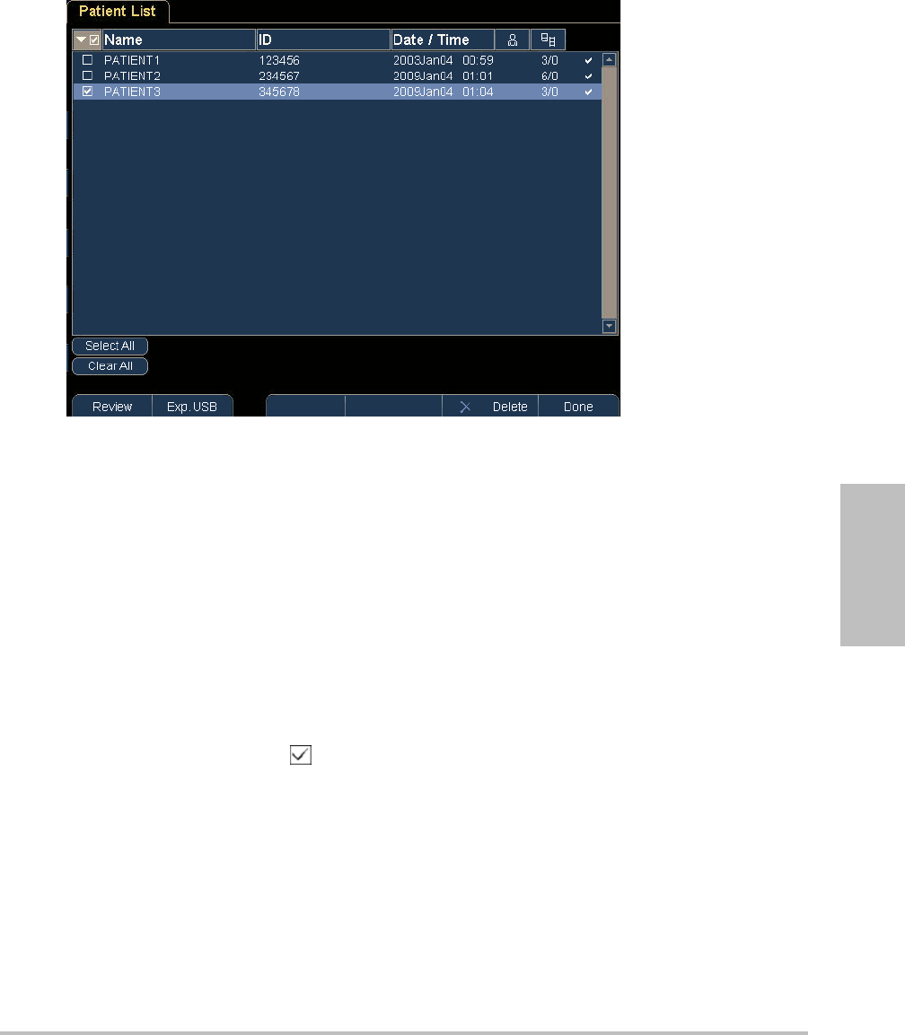
Thepatientlistletsyouorganizesavedimagesandclipsfromacentrallocation.
Field Description
Last
First
Patient name
ID Patient identification number
Exam Exam type
Exam label Exam-specific label that appears in the lower-right screen
User User initials, up to 3 characters. Appears in the patient list and
image header.
Institution Institution name. Appears in the image header.
Caution: If the internal storage icon does not appear in the system status area, internal
storage may be defective. Contact SonoSite Technical Support. (See “SonoSite
Technical Support” on page viii.)
Chapter 3: Imaging 29
Imaging
Figure 3.1 Patient List
To open the patient list
1In2D,pressPatient.
2PressReview
3Ifthereisacurrentpatient,pressList.
To sort the patient list
Afterthesystemstarts,thepatientlistisarrangedbydateandtime,withthemostrecent
patientfilefirst.Youcanre‐sortthepatientlistasneeded.
Clickthecolumnheadingthatyouwanttosortby.Clickitagainifsorting
inreverseorder.
Note: Theselectioncolumnissortable.
To select patients in the patient list
Selectthecheckboxforoneormorepatients.
Clicking Select Allselectsallpatients.
Todeselectpatients,clearcheckedboxesorclickClear All.

30
To review images and clips
Youcanreviewonlyonepatient’simagesandclipsatatime.
1Inthepatientlist,clickthepatientwhoseimagesandclipsyouwanttoreview.
Thepatientrowishighlighted.
2PresstheReviewknob.
Theiconontheknobchangestotwonumbers:thefiledisplayedandthetotalfilessaved.
3Turntheknobtocycletotheimageorclipyouwanttoreview
4(ClipOnly)PressthePlaykey.
Theclipplaysautomaticallyafterloading.Theloadtimedependsoncliplength.
YoucanpressthePausekeytofreezetheclipandcanturntheright‐handknob fora
playbackspeed.
5Turntheleft‐handknobx/xtocycletothenextimageorclipyouwanttoview.
Toreturntothepatientlist,pressList.Toreturntoimaging,pressDone.
Printing, exporting, and deleting images and clips
To print an image
1Verifythataprinterisselected.See“Toconfigurethesystemforaprinter”onpage 18.
2Dooneofthefollowing:
•Inthepatientlist,reviewthepatient’simages.PressPrintwhentheimageappears.
• Freezetheimage,andpressPrint.
To print multiple images
1Verifythataprinterisselected.See“Toconfigurethesystemforaprinter”onpage 18.
2Dooneofthefollowing:
•Printallimagesformultiplepatients:Selectoneormorepatientsinthepatientlist.Then
press Print.
•Printallimagesforonepatient:Highlightthepatientinthepatientlist,andpressPrint.
Eachimageappearsbrieflyon‐screenwhileprinting.
WARNING: To avoid damaging the USB storage device and losing patient data from it,
observe the following:
• Do not remove the USB storage device or turn off the ultrasound system while
the system is exporting.
• Do not bump or otherwise apply pressure to the USB storage device while it is
in a USB port on the ultrasound system. The connector could break.

Chapter 3: Imaging 31
Imaging
To export images and clips to a USB storage device
AUSBstoragedeviceisfortemporarystorageofimagesandclips.Patientexamsshouldbe
archivedregularly.Tospecifyfileformat,see“USBDevicessetup”onpage 20.Apatientexam
mustbeendedbeforeyoucanexportitsimagesandclips.See“Toendtheexam.”
1InserttheUSBstoragedevice.(See“InsertingandremovingUSBstoragedevices”on
page 6.)
2Inthepatientlist,selectthepatientswhoseimagesandclipsyouwanttoexport.
3SelectExp. USB on‐screen.AlistofUSBdevicesappears.
4SelecttheUSBstoragedevice,andselectExport.
OnlyavailableUSBdevices(forexample,notpassword‐protected)areselectable.
ThefilesarefinishedexportingapproximatelyfivesecondsaftertheUSBanimationstops.
RemovingtheUSBstoragedeviceorturningoffthesystemwhileexportingmaycause
exportedfilestobecorruptedorincomplete.Tostopin‐progressexporting,select
Cancel Export.
To delete images and clips
1Selectoneormorepatientsinthepatientlist.
2SelectDeletetodeletetheselectedpatients.Aconfirmationscreenappears.

32
Chapter 4: Measurements 33
Measurements
Chapter 4: Measurements
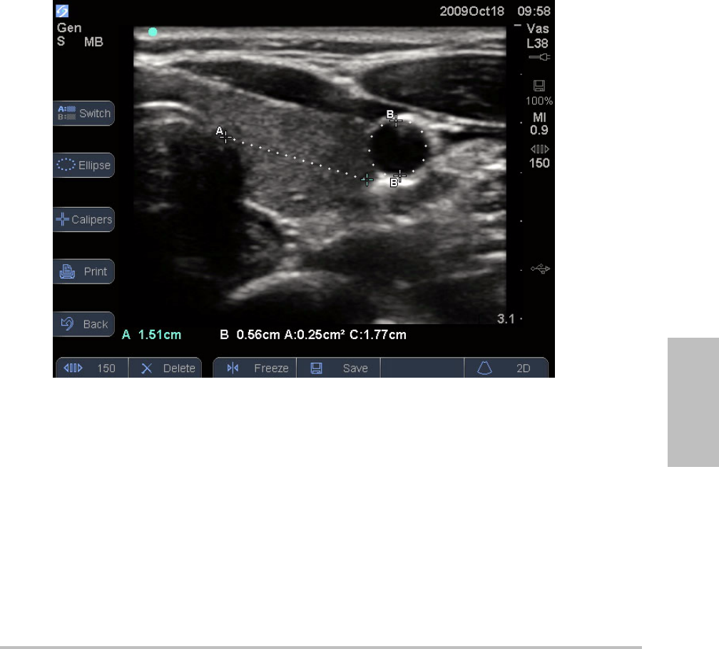
Youcanperformdistance,area,andcircumferencemeasurementsinanyimagingmode.
Measurementsareperformedonfrozenimages.
Youcanperformmultiplemeasurementsatonetime:uptoeightdistancemeasurementsor
fourarea/circumferencemeasurementsoracombination;forexample,sixdistance
measurementsandonearea/circumferencemeasurement.
Figure 4.1 2D image with one distance and one circumference measurement
Working with calipers
Whenmeasuring,youworkwithcalipers.Resultsbasedonthecalipers’positionappearatthe
bottomofthescreen.Theresultsupdateasyourepositionthecalipersbyusingthetouchpad.
YoucanaddcalipersbypressingtheCaliperskey.Youcanhavemultiplesetsofcalipersand
canswitchfromonesettoanother,repositioningthemasneeded.Eachsetshowsthe
measurementresult.Theactivecalipersandmeasurementresultarehighlightedgreen.A
measurementiscompletewhenyoufinishmovingitscalipers.
Foranaccuratemeasurement,accurateplacementofcalipersisessential.

34
To switch the active calipers
Dooneofthefollowing:
•Toswitchtheactivecaliperwithinaset,click.
•Toswitchtheactiveset,pressSwitch.
To delete or edit a measurement
Withthemeasurementactive(highlighted),dooneofthefollowing:
•Todelete,presstheDeleteknob.
•Toedit,usethetouchpadtomovethecalipers.
To improve precision of caliper placement
Doanyofthefollowing:
•Adjustthedisplayformaximumsharpness.
•Useleadingedges(closesttothetransducer)orbordersforstartingandstoppingpoints.
• Maintainaconsistenttransducerorientationforeachtypeofmeasurement.
•Makesurethattheareaofinterestfillsasmuchofthescreenaspossible.
• Minimizethedepth,orzoom.
Distance measurements
Distanceismeasuredincm.
To measure distance
1Onafrozenimage,pressCalipers.
Apairofcalipersappears,connectedbyadottedline.
2Usingthetouchpad,positionthefirstcaliper,andthenclick.
Theothercaliperbecomesactive.
3Usingthetouchpad,positiontheothercaliper.
Ifyoumovethecalipersclosetogether,theyshrinkandthedottedlinedisappears.
Tosavetheimagewiththemeasurementsdisplayed,see“Tosaveanimage”onpage 28.

Chapter 4: Measurements 35
Measurements
Area and circumference measurements
Areaandcircumferencemeasurementsuseanellipsewithcalipers.Youcanmeasurethe
following:
•Areaincm2
• Circumferenceincm
To measure area or circumference
1Onafrozenimage,pressCalipers.
2PressEllipse.
Note: Ifyouexceedtheallowednumberofmeasurements,Ellipseisnotavailable.
3Usethetouchpadtoadjustthesizeandpositionoftheellipse.Clickingtogglesbetween
positionandsize.
Tosavetheimagewiththemeasurementsdisplayed,see“Tosaveanimage”onpage 28.
Measurement accuracy
Themeasurementsprovidedbythesystemdonotdefineaspecificphysiologicaloranatomical
parameter.Rather,themeasurementsareofaphysicalpropertysuchasdistanceforevaluation
bytheclinician.Theaccuracyvaluesrequirethatyoucanplacethecalipersoveronepixel.The
valuesdonotincludeacousticanomaliesofthebody.
The2Dlineardistancemeasurementresultsaredisplayedincentimeterswithoneplacepast
thedecimalpoint,ifthemeasurementistenorgreater;twoplacespastthedecimalpoint,ifthe
measurementislessthanten.
Thelineardistancemeasurementcomponentshavetheaccuracyandrangeshowninthe
followingtables.

36
Sources of measurement errors
Ingeneral,twotypesoferrorscanbeintroducedintothemeasurement:
Acquisition Error Includeserrorsintroducedbytheultrasoundsystemelectronicsrelatingto
signalacquisition,signalconversion,andsignalprocessingfordisplay.Additionally,
computationalanddisplayerrorsareintroducedbythegenerationofthepixelscalefactor,
applicationofthatfactortothecaliperpositionsonthescreen,andthemeasurementdisplay.
Algorithmic Error Theerrorintroducedbymeasurements,whichareinputtohigherorder
calculations.Thiserrorisassociatedwithfloating‐pointversusinteger‐typemath,whichis
subjecttoerrorsintroducedbyroundingversustruncatingresultsfordisplayofagivenlevel
ofsignificantdigitinthecalculation.
Table 1: 2D Measurement Accuracy and Range
2D Measure Accuracy
and Range
System
Tolerancea
Accuracy
By
Tes t
MethodbRange (cm)
Axial Distance < ±2% plus 1% of
full scale
Acquisition Phantom 0-26 cm
Lateral Distance < ±2% plus 1% of
full scale
Acquisition Phantom 0-35 cm
Diagonal Distance < ±2% plus 1% of
full scale
Acquisition Phantom 0-44 cm
Areac< ±4% plus (2% of
full scale/smallest
dimension) * 100
plus 0.5%
Acquisition Phantom 0.01-720 cm2
Circumferenced< ±3% plus (1.4%
of full scale/
smallest
dimension) * 100
plus 0.5%
Acquisition Phantom 0.01-96 cm
a.Full scale for distance implies the maximum depth of the image.
b.An RMI 413a model phantom with 0.7 dB/cm MHz attenuation was used.
c.The area accuracy is defined using the following equation:
% tolerance = ((1 + lateral error) * (1 + axial error) – 1) * 100 + 0.5%.
d.The circumference accuracy is defined as the greater of the lateral or axial accuracy and by the following
equation:
% tolerance = ( (maximum of 2 errors) * 100) + 0.5%.
2

Chapter 5: Troubleshooting and Maintenance 37
Troubleshooting
Chapter 5: Troubleshooting and Maintenance
Thischaptercontainsinformationtohelpcorrectproblemswithsystemoperation,toentera
softwarelicense,andtotakepropercareofthesystem,transducer,andaccessories.
Troubleshooting
Ifyouencounterdifficultywiththesystem,usethefollowingtabletohelptroubleshootthe
problem.Iftheproblempersists,contactSonoSiteTechnicalSupport.(See“SonoSiteTechnical
Support”onpage viii.)
Troubleshooting
Symptom Solution
System does not turn on. Check all power connections.
Remove the DC input connector and battery, wait 10 seconds,
and then reinstall them.
Ensure that the battery is charged.
System image quality is poor. Adjust the LCD screen to improve viewing angle.
Adjust the brightness.
Adjust the gain.
No CPD image. Adjust the gain.
No Color image. Adjust the gain or the scale.
Print does not work. Select the printer on the Connectivity setup page. See “To
configure the system for a printer” on page 18.
Check the printer connections.
Ensure that the printer is turned on and set up properly. See
the printer manufacturer’s instructions, if necessary.
DVD recorder does not record. Check the DVD recorder connections.
Ensure that the DVD recorder is turned on and set up properly.
See the applicable SonoSite accessory user guide and the
manufacturers’ instructions.
System does not recognize the
transducer.
Disconnect and reconnect the transducer.
A maintenance icon
appears on the system screen.
System maintenance may be required. Record the number in
parentheses on the C: line and contact SonoSite or your
SonoSite representative.

38
Software licensing
SonoSitesoftwareiscontrolledbyalicensekey.Afteryouinstallnewsoftware,thesystem
promptsyouforalicensekey.Youmustobtainonekeyforeachsystemortransducerthatuses
thesoftware.
Thesoftwarewilloperateforashorttime(the“graceperiod”)withoutalicensekey.Duringthe
graceperiod,allsystemfunctionsareavailable.Afterthegraceperiod,thesystemisnotusable
untilyouenteravalidlicensekey.Graceperiodtimeisnotusedwhilethesystemisoffor
asleep.Graceperiodtimeremainingappearsonthelicenseupdatescreen.
Toobtainalicensekeyforyoursoftware,contactSonoSiteTechnicalSupport.(See“SonoSite
TechnicalSupport”onpage viii.)Youneedtoprovidethefollowinginformation.(See“System
Informationsetup”onpage 20.)
Afteryouobtainalicensekey,youmustenteritintothesystem.
To enter a license key
1Turnonthesystem.
Thelicenseupdatescreenappears.
2EnterthelicensekeyintheEnter license numberfield.
3SelectDoneon‐screen.
Ifyouenteredavalidlicensekeybutthelicenseupdatescreenappears,verifythatyou
enteredthelicensekeycorrectly.Ifthelicenseupdatescreenstillappears,contactSonoSite
TechnicalSupport.(See“SonoSiteTechnicalSupport”onpage viii.)
Caution: After the grace period expires, all system functions except licensing are unavailable
until a valid license key is entered.
Software License Key Information
System Software Transducer Software
Name of institution installing the upgrade Name of institution installing the upgrade
Serial number (on bottom of system) Transducer serial number
ARM version Transducer part number (REF)
or model number (for example, C60x)
PCBA serial number Transducer bundle version

Chapter 5: Troubleshooting and Maintenance 39
Troubleshooting
Maintenance
Usetherecommendationsinthissectionwhencleaningordisinfectingyourultrasound
system,transducer,andaccessories.Usethecleaningrecommendationsintheperipheral
manufacturer’sinstructionswhencleaningordisinfectingyourperipherals.
Noperiodicorpreventivemaintenanceisrequiredforthesystem,transducer,oraccessories
otherthancleaninganddisinfectingthetransduceraftereveryuse.(See“Cleaningand
disinfectingtransducers”onpage 41.)Therearenointernalcomponentsthatrequireperiodic
testingorcalibration.Allmaintenancerequirementsaredescribedinthischapterandinthe
ultrasoundsystemservicemanual.Performingmaintenanceproceduresnotdescribedinthe
userguideorservicemanualmayvoidtheproductwarranty.
ContactSonoSiteTechnicalSupportforanymaintenancequestions.(See“SonoSiteTechnical
Support”onpage viii.)
WARNING: Disinfectants and cleaning methods listed are recommended by SonoSite for
compatibility with product materials, not for biological effectiveness. Refer to the
disinfectant label instructions for guidance on disinfection efficacy and appropriate
clinical uses.
The level of disinfection required for a device is dictated by the type of tissue it will
contact during use. To avoid infection, ensure that the disinfectant type is
appropriate for the equipment. For information, see the disinfectant label
instructions and the recommendations of the Association for Professionals in
Infection Control and Epidemiology (APIC) and the U.S. Food and Drug
Administration (FDA).
To prevent contamination, the use of sterile transducer sheaths and sterile coupling
gel is recommended for clinical applications of an invasive or surgical nature. Do not
apply the transducer sheath and gel until you are ready to perform the procedure.
Caution: Some transducer sheaths contain natural rubber latex and talc, which can cause
allergic reactions in some individuals. Refer to 21 CFR 801.437, User labeling for
devices that contain natural rubber.

40
Cleaning and disinfecting the ultrasound system
Theexteriorsurfaceoftheultrasoundsystemandtheaccessoriescanbecleanedand
disinfectedusingarecommendedcleanerordisinfectant.SeeTable 1,“Disinfectants
CompatiblewithSystemandTransducers”onpage 44.
To clean the LCD screen
Dampenaclean,non‐abrasive,cottonclothwithanethanolic‐basedliquidcleaner,andwipe
thescreenclean.
Applythecleanertotheclothratherthanthesurfaceofthescreen.
To clean and disinfect system surfaces
1Turnoffthesystem.
2Disconnectthesystemfromthepowersupply,orremoveitfromthestand.
3Cleantheexteriorsurfacesusingasoftclothlightlydampenedinamildsoapordetergent
cleaningsolutiontoremoveanyparticulatematterorbodyfluids.
Applythesolutiontotheclothratherthanthesurface.
WARNING: To avoid electrical shock, before cleaning, disconnect the system from the power
supply or remove it from the stand.
To avoid infection always use protective eyewear and gloves when performing
cleaning and disinfecting procedures.
To avoid infection, ensure that the solution expiration date has not passed.
To avoid infection, the level of disinfection required for a product is dictated by the
type of tissue it contacts during use. Ensure that the solution strength and duration
of contact are appropriate for the equipment. For information, see the disinfectant
label instructions and the recommendations of the Association for Professionals in
Infection Control and Epidemiology (APIC) and FDA.
Caution: Do not spray cleaners or disinfectant directly on the system surfaces. Doing so may
cause solution to leak into the system, damaging the system and voiding the
warranty.
Do not use strong solvents such as thinner or benzene, or abrasive cleansers, since
these will damage the exterior surfaces.
Use only recommended cleaners or disinfectants on system surfaces.
Immersion-type disinfectants are not approved for use on system surfaces.
When you clean the system, ensure that the solution does not get inside the system
controls or the battery compartment.
Do not scratch the LCD screen.

Chapter 5: Troubleshooting and Maintenance 41
Troubleshooting
4Mixthedisinfectantsolutioncompatiblewiththesystem,followingdisinfectantlabel
instructionsforsolutionstrengthsanddisinfectantcontactduration.
5Wipesurfaceswiththedisinfectantsolution.
6Airdryortoweldrywithacleancloth.
Cleaning and disinfecting transducers
Todisinfectthetransduceranditscable,usetheimmersionmethodorthewipemethod.
Immersibletransducerscanbedisinfectedonlyiftheproductlabelingindicatestheycanbe
usedwithanimmersionmethod.
SeeTable 1,“DisinfectantsCompatiblewithSystemandTransducers”onpage 44.
WARNING: To avoid electrical shock, before cleaning, disconnect the transducer from the
system.
To avoid injury, always use protective eyewear and gloves when performing
cleaning and disinfecting procedures.
To avoid infection, ensure that the solution expiration date has not passed.
To avoid infection, the level of disinfection required for a transducer is dictated by
the type of tissue it contacts during use. Ensure that the solution strength and
duration of contact are appropriate for the equipment. SonoSite tests products for
compatibility of materials only. SonoSite does not test for biological effectiveness.
For information, see the disinfectant label instructions and the recommendations of
the Association for Professionals in Infection Control and Epidemiology (APIC) and
FDA.
Caution: Transducers must be cleaned after every use. Cleaning transducers is necessary prior
to effective disinfection. Ensure that you follow the manufacturer's instructions
when using disinfectants.
Do not use a surgeon's brush when cleaning transducers. Even the use of soft
brushes can damage a transducer. Use a soft cloth.
Using a non-recommended cleaning or disinfection solution, incorrect solution
strength, or immersing a transducer deeper or for a longer period of time than
recommended can damage or discolor the transducer and void the transducer
warranty.
Do not allow cleaning solution or disinfectant into the transducer connector.
Do not allow disinfectant to contact metal surfaces. Use a soft cloth lightly
dampened in a mild soap or compatible cleaning solution to remove any
disinfectant that remains on metal surfaces.
Attempting to disinfect a transducer or transducer cable using a method other than
the one included here can damage the transducer and void the warranty.

42
To clean and disinfect a transducer (wipe method)
1Disconnectthetransducerfromthesystem.
2Removeanytransducersheath.
3Cleanthesurfaceusingasoftclothlightlydampenedinamildsoapordetergentcleaning
solutiontoremoveanyparticulatematterorbodyfluids.
Applythesolutiontotheclothratherthanthesurface.
4Rinsewithwaterorwipewithwater‐dampenedcloth,thenwipewithadrycloth.
5Mixthedisinfectantsolutioncompatiblewiththetransducer,followingdisinfectantlabel
instructionsforsolutionstrengthsanddisinfectantcontactduration.
6Wipesurfaceswiththedisinfectantsolution.
7Airdryortoweldrywithacleancloth.
8Examinethetransducerandcablefordamagesuchascracks,splitting,orfluidleaks.
Ifdamageisevident,discontinueuseofthetransducer,andcontactSonoSiteoryourlocal
representative.
To clean and disinfect a transducer (immersion method)
1Disconnectthetransducerfromthesystem.
2Removeanytransducersheath.
3Cleanthesurfaceusingasoftclothlightlydampenedinamildsoaporcompatiblecleaning
solutiontoremoveanyparticulatematterorbodyfluids.
Applythesolutiontotheclothratherthanthesurface.
4Rinsewithwaterorawipewithwater‐dampenedcloth,andthenwipewithadrycloth.
5Mixthedisinfectantsolutioncompatiblewiththetransducer,followingdisinfectantlabel
instructionsforsolutionstrengthsanddisinfectantcontactduration.
6Immersethetransducerintothedisinfectionsolutionnotmorethan12‐18 inches(31‐46 cm)
fromthepointwherethecableenterstheconnector.
Followtheinstructionsonthedisinfectantlabelforthedurationofthetransducer
immersion.
7Usingtheinstructionsonthedisinfectantlabel,rinsetothepointofthepreviousimmersion,
andthenairdryortoweldrywithacleancloth.
8Examinethetransducerandcablefordamagesuchascracks,splitting,orfluidleaks.
Ifdamageisevident,discontinueuseofthetransducer,andcontactSonoSiteoryourlocal
representative.

Chapter 5: Troubleshooting and Maintenance 43
Troubleshooting
Cleaning and disinfecting the battery
To clean and disinfect a battery (wipe method)
1Removethebatteryfromthesystem.
2Cleanthesurfaceusingasoftclothlightlydampenedinamildsoapordetergentcleaning
solution.
Applythesolutiontotheclothratherthanthesurface.
3Wipethesurfaceswiththedisinfectionsolution.Theracidedisinfectantisrecommended.
4Airdryortoweldrywithacleancloth.
Caution: To avoid damaging the battery, do not allow cleaning solution or disinfectant to
come in contact with the battery terminals.

44
Seewww.sonosite.comforupdatedcleaninganddisinfectantinformation.ClickQuick Link,andthenclick
Documentation.
Table 1 does not have the following regulatory information for disinfectants:
•EPA Registration
• FDA 510(k) clearance (liquid sterilant, high level disinfectant)
• CE approval
Prior to use, confirm that the regulatory status of the disinfectant is appropriate for
your jurisdiction and use.
Table 1: Disinfectants Compatible with System and Transducers
Disinfection and
Cleaning Solutions
Country
of Origin Type Active Ingredient C60x/ICTx/
L38x/P21x HFL38x C11x/
L25x
System
Surfaces
AbcoCide 14 USA Liquid Gluteraldehyde A A A U
Accel Wipes CAN Wipe Hydrogen Peroxide A A A U
Accel Plus CAN Wipe Hydrogen Peroxide N N N U
Accel TB CAN Wipe Hydrogen Peroxide N N N U
Aidal Plus AUS Liquid Gluteraldehyde A A A U
Alkacide FRA Liquid Gluteraldehyde A A A U
Alkazyme FRA Liquid Quat. Ammonia A A A U
Anioxy-Twin FRA Liquid Peracetic Acid N N N U
Aquatabs (1000) IRL Tablet Sodium
Dichloroisocyanurate
ANAU
Aquatabs (2000) IRL Tablet Sodium
Dichloroisocyanurate
ANAU

Chapter 5: Troubleshooting and Maintenance 45
Troubleshooting
Aquatabs (5000) IRL Tablet Sodium
Dichloroisocyanurate
NNNU
Anioxyde 1000 FRA Liquid Peracetic Acid N N N U
Ascend USA Liquid Quat Ammonia A A A U
Asepti-HB USA Liquid Quat Ammonia A A A U
Asepti-Steryl USA Spray Ethanol A A A N
Asepti-Wipes USA Wipe Propanol (Isopropyl
Alcohol
AAAA
Bacillocid rasant DEU Liquid Glut./Quat. Ammonia A A A U
Banicide USA Liquid Gluteraldehyde A U A U
Bleach USA Liquid NaCl Hypochlorite A A A U
Cavicide USA Liquid Isopropyl A A A U
Caviwipes USA Wipes Isopropanol A A N U
Chlor-Clean GBR Liquid Sodium
Dichloroisocyanurate
ANAU
Cidalkan Lingettes FRA Wipes Ethyl Alcohol A A U U
Cidex USA Liquid Gluteraldehyde A A A A
Cidex OPA USA Liquid Ortho-phthaldehyde A A A U
Cidex Plus USA Liquid Gluteraldehyde A A A A
Cleanisept DEU Wipes Quat Ammonia A A A A
Clorox Wipes USA Wipes Isopropanol A A A U
Table 1: Disinfectants Compatible with System and Transducers (Continued)
Disinfection and
Cleaning Solutions
Country
of Origin Type Active Ingredient C60x/ICTx/
L38x/P21x HFL38x C11x/
L25x
System
Surfaces

46
Control III USA Liquid Quat. Ammonia A A N U
Coverage Spray USA Spray Quat. Ammonia A A N N
DentaSept FRA Liquid Quat. Ammonia N N N U
Denatured Alcohol USA Liquid Ethanol N N N U
DisCide Wipes USA Wipes Isopropyl Alcohol A A A U
DisOPA JPN Liquid Ortho-phthaldehyde A A A U
Dispatch USA Spray NaCl Hypochlorite A A A U
Dynacide PA FRA Liquid Peracetic Acid A A A U
End-Bac II USA Liquid Quat. Ammonia A A A N
Endozime AW Plus FRA Liquid Propanol A A A U
Envirocide USA Liquid Isopropyl A U N U
Enzol USA Cleaner Ethylene Glycol A A A U
Expose USA Liquid Isopropyl A A A U
Gigasept AF DEU Liquid Quat. Ammonia A A A U
Gigasept FF DEU Liquid Bersteinsaure N N N U
Gluteraldehyde SDS USA Liquid Gluteraldehyde A U A U
Hexanios FRA Liquid Polyhexanide/Quat.
Ammonia
AAAU
Hi Tor Plus USA Liquid Chloride A A N U
Hibiclens USA Cleaner Chlorhexidine A A A U
Table 1: Disinfectants Compatible with System and Transducers (Continued)
Disinfection and
Cleaning Solutions
Country
of Origin Type Active Ingredient C60x/ICTx/
L38x/P21x HFL38x C11x/
L25x
System
Surfaces

Chapter 5: Troubleshooting and Maintenance 47
Troubleshooting
Hydrogen Peroxide USA Liquid Hydrogen Peroxide A A A U
Isopropanol Alcohol ALL Liquid Alcohol N N N U
Kodan Tücher DEU Liquid Propanol A A A U
Kohrsolin ff DEU Liquid Gluteraldehyde A U A U
Korsolex basic DEU Liquid Gluteraldehyde N N N U
Korsolex extra DEU Liquid Ethanol/Propanol A A A U
Lem-O-Quat USA Liquid Alkyl/Chloride N N N U
LpHse USA Liquid O-phenylphenol A A A U
Lysol USA Spray Ethanol N N N N
Lysol IC USA Liquid O-phenylphenol A N A U
Madacide 1 USA Liquid Isopropanol A A N A
Matar USA Liquid O-phenylphenol A U A U
MetriCide 14 USA Liquid Gluteraldehyde A A A U
MetriCide 28 USA Liquid Gluteraldehyde A A A U
MetriZyme USA Cleaner Propylene Glycol A A A U
Mikrobak forte DEU Liquid Ammonium Chloride A A A U
Mikrozid Wipes DEU Wipe Ethanol/Propanol A A A U
Nuclean FRA Spray Alcohol/Biguanide A A A U
Precise USA Spray O-phenylphenol N N N U
Prevention CAN Liquid Hydrogen Peroxide N N N U
Table 1: Disinfectants Compatible with System and Transducers (Continued)
Disinfection and
Cleaning Solutions
Country
of Origin Type Active Ingredient C60x/ICTx/
L38x/P21x HFL38x C11x/
L25x
System
Surfaces

48
Ruthless USA Spray Quat. Ammonia A A N U
Sagrosept Wipe DEU Wipe Propanol A A A U
Salvanios pH 7 FRA Liquid Quat. Ammonia A A A U
Sani-Cloth HB USA Wipe Quat. Ammonia A A N A
Sani-Cloth Plus USA Wipe Quat. Ammonia A A A A
Sekusept DEU Liquid Gluteraldehyde A A A U
Sklar USA Liquid Isopropanol A A N U
Sporicidin USA Liquid Phenol A A A N
Sporicidin Wipes USA Wipe Phenol A A A A
Staphene USA Spray Ethanol A N A U
Steranios FRA Liquid Gluteraldehyde A A A U
Super Sani-Cloth USA Wipe Isopropyl Alcohol N N N N
T-Spray USA Spray Quat. Ammonia A A N N
T-Spray II USA Spray Alkyl/Chloride A A A U
TASK 105 USA Spray Quat. Ammonia A A A U
TBQ USA Liquid Quat. Ammonia A A A U
Theracide Plus USA Liquid Quat. Ammonia A A A U
Theracide Plus
Wipes
USA Wipe Quat. Ammonia A A A A
Tor USA Liquid Quat. Ammonia A A N U
Table 1: Disinfectants Compatible with System and Transducers (Continued)
Disinfection and
Cleaning Solutions
Country
of Origin Type Active Ingredient C60x/ICTx/
L38x/P21x HFL38x C11x/
L25x
System
Surfaces

Chapter 5: Troubleshooting and Maintenance 49
Troubleshooting
Transeptic USA Cleaner Alcohol N N N U
Tristel GBR Liquid Chlorine Dioxide A A A U
Tristel Wipes GBR Wipe Chlorine Dioxide N N N N
Vesphene II USA Liquid Sodium/
o-Phenylphenate
AAAU
Virex II 256 USA Liquid Ammonium Chloride A A A U
Virex TB USA Liquid Quat. Ammonia A A N N
Virox 5 CAN Wipe Hydrogen Peroxide A A A U
Virufen FRA Liquid Alkyl Ammonium
Chloride
AAAU
Wavicide -01 USA Liquid Gluteraldehyde N N N U
Wavicide -06 USA Liquid Gluteraldehyde A A A U
Wex-Cide USA Liquid O-phenylphenol A A A U
A = Acceptable
N = Not acceptable (Do not use)
U = Untested (Do not use)
Table 1: Disinfectants Compatible with System and Transducers (Continued)
Disinfection and
Cleaning Solutions
Country
of Origin Type Active Ingredient C60x/ICTx/
L38x/P21x HFL38x C11x/
L25x
System
Surfaces

50

Chapter 6: Safety 51
Safety
Chapter 6: Safety
Thischaptercontainsinformationrequiredbyregulatoryagencies,includinginformation
abouttheALARA(aslowasreasonablyachievable)principle,theoutputdisplaystandard,
acousticpowerandintensitytables,andothersafetyinformation.Theinformationappliesto
theultrasoundsystem,transducer,accessories,andperipherals.
Ergonomic safety
Thesehealthyscanningguidelinesareintendedtoassistyouinthecomfortandeffectiveuse
ofyourultrasoundsystem.
WARNING: To prevent musculoskeletal disorders, follow the guidelines in this section.
Use of an ultrasound system may be linked to musculoskeletal disordersa,b,c.
Use of an ultrasound system is defined as the physical interaction among the
operator, the ultrasound system, and the transducer.
When using an ultrasound system, as with many similar physical activities, you may
experience occasional discomfort in your hands, fingers, arms, shoulders, eyes, back,
or other parts of your body. However, if you experience symptoms such as constant
or recurring discomfort, pain, throbbing, aching, tingling, numbness, burning
sensation, or stiffness, do not ignore these warning signs. Promptly see a qualified
health professional. Symptoms such as these can be linked with musculoskeletal
disorders (MSDs). MSDs can be painful and may result in potentially disabling
injuries to the nerves, muscles, tendons, or other parts of the body. Examples of
MSDs include carpal tunnel syndrome and tendonitis.
While researchers are not able to definitively answer many questions about MSDs,
there is a general agreement that certain factors are associated with their
occurrence including: preexisting medical and physical conditions, overall health,
equipment and body position while doing work, frequency of work, duration of
work, and other physical activities that may facilitate the onset of MSDsd. This
chapter provides guidelines that may help you work more comfortably and may
reduce your risk of MSDse,f.
a.Magnavita, N., L. Bevilacqua, P. Mirk, A. Fileni, and N. Castellino. “Work-related Musculoskeletal Complaints
in Sonologists.” Occupational Environmental Medicine. 41:11 (1999), 981-988.
b.Craig, M. “Sonography: An Occupational Hazard?” Journal of Diagnostic Medical Sonography. 3 (1985),
121-125.
c.Smith, C.S., G.W. Wolf, G. Y. Xie, and M. D. Smith. “Musculoskeletal Pain in Cardiac Ultrasonographers:
Results of a Random Survey.” Journal of American Society of Echocardiography. (May1997), 357-362.
d.Wihlidal, L.M. and S. Kumar. “An Injury Profile of Practicing Diagnostic Medical Sonographers in Alberta.”
International Journal of Industrial Ergonomics. 19 (1997), 205-216.

52
Position the system
Promote comfortable shoulder, arm, and hand postures
Useastandtosupporttheweightoftheultrasoundsystem.
Minimize eye and neck strain
•Whentheexamorprocedureallows,positionthesystemwithinreach.
•Adjusttheangleofthesystemanddisplaytominimizeglarefromoverheadoroutside
lighting.
•Ifusingastand,adjustitsheightsothatthedisplayisatorslightlybeloweyelevel.
Position yourself
Support your back during an exam
•Useachairthathassupportforyourlowerback,thatadjuststoyourworksurfaceheight,
thatpromotesanaturalbodyposture,andthatallowsforquickheightadjustments.
•Alwayssitorstandinanuprightmanner.Avoidbendingorstooping.
Minimize reaching and twisting
•Useabedthatisheightadjustable.
•Positionthepatientasclosetoyouaspossible.
•Faceforward.Avoidtwistingyourheadorbody.
•Moveyourentirebodyfronttoback,andpositionyourscanningarmnexttoorslightlyin
frontofyou.
•Standfordifficultexamstominimizereaching.
Promote comfortable shoulder and arm postures
•Keepyourelbowclosetoyourside.
•Relaxyourshouldersinalevelposition.
• Supportyourarmusingasupportcushionorpillow,orrestitonthebed.
Minimize neck bending and twisting
Positiontheultrasoundsystemdirectlyinfrontofyou.
e.Habes, D.J. and S. Baron. “Health Hazard Report 99-0093-2749.” University of Medicine and Dentistry of New
Jersey. (1999).
f.Vanderpool, H.E., E.A. Friis, B.S. Smith, and K.L. Harms. “Prevalence of Carpal Tunnel Syndrome and Other
Work-related Musculoskeletal Problems in Cardiac Sonographers.” Journal of Medicine. 35:6 (1993), 605-610.

Chapter 6: Safety 53
Safety
Promote comfortable hand, wrist, and finger postures
•Holdthetransducerlightlyinyourfingers.
• Minimizethepressureappliedonthepatient.
•Keepyourwristinastraightposition.
Take breaks, exercise, and vary activities
• Minimizingscanningtimeandtakingbreakscaneffectivelyallowyourbodytorecoverfrom
physicalactivityandhelpyouavoidMSDs.Someultrasoundtasksmayrequirelongeror
morefrequentbreaks.Onewayoftakingabreakistostopandrelax.However,simply
changingtaskscanhelpsomemusclegroupsrelaxwhileothersremainorbecomeactive.
•Workefficientlybyusingthesoftwareandhardwarefeaturescorrectly.
•Keepmoving.Avoidsustainingthesameposturebyvaryingyourhead,neck,body,arm,
andlegpositions.
•Targetedexercisescanstrengthenmusclegroups,whichmayhelpyouavoidMSDs.Contact
aqualifiedhealthprofessionaltodeterminestretchesandexercisesthatarerightforyou.
Electrical safety classification
Electrical safety
ThissystemmeetsEN60601‐1,ClassI/internally‐poweredequipmentrequirementsandType
BFisolatedpatient‐appliedpartssafetyrequirements.
Thissystemcomplieswiththeapplicablemedicalequipmentrequirementspublishedinthe
CanadianStandardsAssociation(CSA),EuropeanNormHarmonizedStandards,and
UnderwritersLaboratories(UL)safetystandards.SeeChapter 7,“Specifications.”
Class I equipment Ultrasound system powered from power supply or part
of the S Series stand.
Internally powered equipment Ultrasound system not connected to the power supply
(battery only)
Type BF applied parts Ultrasound transducers
IPX-7 (watertight equipment) Ultrasound transducers
Non AP/APG Ultrasound system power supply, S Series stand, and
peripherals. Equipment is not suitable for use in the
presence of flammable anaesthetics.

54
Formaximumsafetyobservethefollowingwarningsandcautions.
WARNING: To avoid discomfort or minor risk of patient injury, keep hot surfaces away from the
patient.
Under certain circumstances, the transducer connector and back of the display
enclosure can reach temperatures that exceed EN60601-1 limits for patient contact,
therefore only the operator shall handle the system. This does not include the
transducer face.
To avoid discomfort or minor risk of operator injury when handling the transducer
connector, the system should not be operated for more than 60 minutes
continuously in a live-scan mode (as opposed to freeze or sleep modes).
To avoid the risk of electrical shock or injury, do not open the system enclosures. All
internal adjustments and replacements, except battery replacement, must be made
by a qualified technician.
To avoid the risk of injury, do not operate the system in the presence of flammable
gasses or anesthetics. Explosion can result.
To avoid the risk of electrical shock, use only properly grounded equipment. Shock
hazards exist if the power supply is not properly grounded. Grounding reliability can
only be achieved when equipment is connected to a receptacle marked “Hospital
Only” or “Hospital Grade” or the equivalent. The grounding wire must not be
removed or defeated.
To avoid the risk of electrical shock, when using the system in an environment where
the integrity of the protective earth conductor arrangement is in doubt, operate the
system on battery power only without using the power supply.
To avoid the risk of electrical shock, do not connect the system’s power supply or the
S Stand’s auxiliary mains outlet receptacles to an MPSO or extension cord.
To avoid the risk of electrical shock, before using the transducer, inspect the
transducer face, housing, and cable. Do not use the transducer if the transducer or
cable is damaged.
To avoid the risk of electrical shock, always disconnect the power supply from the
system before cleaning the system.
To avoid the risk of electrical shock, do not use any transducer that has been
immersed beyond the specified cleaning or disinfection level. See Chapter 5,
“Troubleshooting and Maintenance.”
To avoid the risk of electrical shock and fire hazard, inspect the power supply, AC
power cord, and plug on a regular basis. Ensure they are not damaged.
To avoid the risk of electrical shock and fire hazard, the power cord set that connects
the power supply of the ultrasound system or S Series stand to mains power must
only be used with the power supply or S Series stand, and cannot be used to
connect other devices to mains power.

Chapter 6: Safety 55
Safety
WARNING: To avoid the risk of electrical shock, use only accessories and peripherals
recommended by SonoSite, including the power supply. Connection of accessories
and peripherals not recommended by SonoSite could result in electrical shock.
Contact SonoSite or your local representative for a list of accessories and peripherals
available from or recommend by SonoSite.
To avoid the risk of electrical shock, inspect cables and power cords used within the
system on a regular basis for damage.
To avoid the risk of electrical shock to the patient/subject, do not touch the system
battery contacts while simultaneously touching a patient/subject.
To prevent injury to the operator/bystander, the transducer must be removed from
patient contact before the application of a high-voltage defibrillation pulse.
To avoid possible electrical shock or electromagnetic interference, verify proper
operation and compliance with relevant safety standards for all equipment before
clinical use. Connecting additional equipment to the ultrasound system constitutes
configuring a medical system. SonoSite recommends verifying that the system, all
combinations of equipment, and accessories connected to the ultrasound system
comply with JACHO installation requirements and/or safety standards such as
AAMI-ES1, NFPA 99 OR IEC Standard 60601-1-1 and electromagnetic compatibility
standard IEC 60601-1-2 (Electromagnetic compatibility), and are certified according
to IEC Standard 60950 (Information Technology Equipment (ITE)).
Caution: Do not use the system if an error message appears on the image display: note the
error code; call SonoSite or your local representative; turn off the system by pressing
and holding the power key until the system powers down.
To avoid increasing the system and transducer connector temperature, do not block
the airflow to the ventilation holes on the back of the system.

56
Equipment safety
Toprotectyourultrasoundsystem,transducer,andaccessories,followtheseprecautions.
Battery safety
Topreventthebatteryfrombursting,igniting,oremittingfumesandcausingpersonalinjury
orequipmentdamage,observethefollowingprecautions.
Caution: Excessive bending or twisting of cables can cause a failure or intermittent operation.
Improper cleaning or disinfecting of any part of the system can cause permanent
damage. For cleaning and disinfecting instructions, see Chapter 5, “Troubleshooting
and Maintenance.”
Do not submerge the transducer connector in solution. The cable is not liquid-tight
beyond the transducer connector/cable interface.
Do not use solvents such as thinner or benzene, or abrasive cleaners on any part of
the system.
Remove the battery from the system if the system is not likely to be used for some
time.
Do not spill liquid on the system.
WARNING: The battery has a safety device. Do not disassemble or alter the battery.
Charge the batteries only when the ambient temperature is between 0° and 40°C
(32° and 104°F).
Do not short-circuit the battery by directly connecting the positive and negative
terminals with metal objects.
Do not heat the battery or discard it in a fire.
Do not expose the battery to temperatures over 60°C (140°F). Keep it away from fire
and other heat sources.
Do not charge the battery near a heat source, such as a fire or heater.
Do not leave the battery in direct sunlight.
Do not pierce the battery with a sharp object, hit it, or step on it.
Do not use a damaged battery.
Do not solder a battery.
The polarity of the battery terminals are fixed and cannot be switched or reversed.
Do not force the battery into the system.
Do not connect the battery to an electrical power outlet.

Chapter 6: Safety 57
Safety
Clinical safety
Observethefollowingprecautionsrelatedtoclinicalsafety.
WARNING: Do not continue recharging the battery if it does not recharge after two successive
six hour charging cycles.
If the battery leaks or emits an odor, remove it from all possible flammable sources.
Caution: To avoid the battery bursting, igniting, or emitting fumes from the battery and
causing equipment damage, observe the following precautions:
Do not immerse the battery in water or allow it to get wet.
Do not put the battery into a microwave oven or pressurized container.
If the battery emits an odor or heat, is deformed or discolored, or in any way appears
abnormal during use, recharging or storage, immediately remove it and stop using
it. If you have any questions about the battery, consult SonoSite or your local
representative.
Store the battery between -20°C (-4°F) and 60°C (140°F).
Use only SonoSite batteries.
Do not use or charge the battery with non-SonoSite equipment. Only charge the
battery with the system.
WARNING: Non-medical (commercial) grade peripheral monitors have not been verified or
validated by SonoSite as being suitable for diagnosis.
To avoid the risk of a burn hazard, do not use the transducer with high frequency
surgical equipment. Such a hazard may occur in the event of a defect in the high
frequency surgical neutral electrode connection.
Do not use the system if it exhibits erratic or inconsistent behavior. Discontinuities in
the scanning sequence are indicative of a hardware failure that must be corrected
before use.
Some transducer sheaths contain natural rubber latex and talc, which can cause
allergic reactions in some individuals. Refer to 21 CFR 801.437, User labeling for
devices that contain natural rubber.
Perform ultrasound procedures prudently. Use the ALARA (as low as reasonably
achievable) principle and follow the prudent use information concerning MI and TI.

58
Electromagnetic compatibility
Theultrasoundsystemhasbeentestedandfoundtocomplywiththeelectromagnetic
compatibility(EMC)limitsformedicaldevicestoIEC60601‐1‐2:2001.Theselimitsaredesigned
toprovidereasonableprotectionagainstharmfulinterferenceinatypicalmedicalinstallation.
WARNING: SonoSite does not currently recommend a specific brand of acoustic standoff. If an
acoustic standoff is used, it must have a minimum attentuation of .3dB/cm/MHz.
Some SonoSite transducers are approved for intraoperative applications if a
market-cleared sheath is used.
Caution: Medical electrical equipment requires special precautions regarding EMC and must
be installed and operated according to these instructions. It is possible that high
levels of radiated or conducted radio-frequency electromagnetic interference (EMI)
from portable and mobile RF communications equipment or other strong or nearby
radio-frequency sources, could result in performance disruption of the ultrasound
system. Evidence of disruption may include image degradation or distortion, erratic
readings, equipment ceasing to operate, or other incorrect functioning. If this occurs,
survey the site to determine the source of disruption, and take the following actions
to eliminate the source(s).
•Turn equipment in the vicinity off and on to isolate disruptive equipment.
•Relocate or re-orient interfering equipment.
•Increase distance between interfering equipment and your ultrasound system.
•Manage use of frequencies close to ultrasound system frequencies.
•Remove devices that are highly susceptible to EMI.
•Lower power from internal sources within facility control (such as paging
systems).
•Label devices susceptible to EMI.
•Educate clinical staff to recognize potential EMI-related problems.
•Eliminate or reduce EMI with technical solutions (such as shielding).
•Restrict use of personal communicators (cell phones, computers) in areas with
devices susceptible to EMI.
•Share relevant EMI information with others, particularly when evaluating new
equipment purchases which may generate EMI.
•Purchase medical devices that comply with IEC 60601-1-2 EMC Standards.

Chapter 6: Safety 59
Safety
Manufacturer’s declaration
Table 1andTable 2documenttheintendeduseenvironmentandEMCcompliancelevelsofthe
system.Formaximumperformance,ensurethatthesystemisusedintheenvironments
describedinthistable.
Thesystemisintendedforuseintheelectromagneticenvironmentspecifiedbelow.
Caution: To avoid the risk of increased electromagnetic emissions or decreased immunity, use
only accessories and peripherals recommended by SonoSite. Connection of
accessories and peripherals not recommended by SonoSite could result in
malfunctioning of your ultrasound system or other medical electrical devices in the
area. Contact SonoSite or your local representative for a list of accessories and
peripherals available from or recommended by SonoSite. See the SonoSite
accessories user guide.
Electrostatic discharge (ESD), or static shock, is a naturally occurring phenomenon.
ESD is common in conditions of low humidity, which can be caused by heating or air
conditioning. Static shock is a discharge of the electrical energy from a charged
body to a lesser or non-charged body. The degree of discharge can be significant
enough to cause damage to a transducer or an ultrasound system. The following
precautions can help reduce ESD: anti-static spray on carpets, anti-static spray on
linoleum, and anti-static mats.
Table 1: Manufacturer’s Declaration - Electromagnetic Emissions
Emissions Test Compliance Electromagnetic Environment
RF emissions
ClSPR 11
Group 1 The SonoSite ultrasound system uses RF energy only
for its internal function. Therefore, its RF emissions
are very low and are not likely to cause any
interference in nearby electronic equipment.
RF emissions
ClSPR 11
Class A The SonoSite ultrasound system is suitable for use in
all establishments other than domestic and those
directly connected to the public low-voltage power
supply network which supplies buildings used for
domestic purposes.
Harmonic emissions
IEC 61000-3-2
Class A
Voltage fluctuations/
flicker emissions
IEC 61000-3-3
Complies

60
Thesystemisintendedforuseintheelectromagneticenvironmentspecifiedbelow.
Table 2: Manufacturer’s Declaration - Electromagnetic Immunity
Immunity Test IEC 60601 Test Level Compliance Level Electromagnetic
Environment
Electrostatic
Discharge (ESD)
IEC 61000-4-2
2.0KV, 4.0KV, 6.0KV
contact
2.0KV, 4.0KV, 8.0KV air
2.0KV, 4.0KV, 6.0KV
contact
2.0KV, 4.0KV, 8.0KV
air
Floors should be wood,
concrete or ceramic tile. If
floors are covered with
synthetic material, the relative
humidity should be at least
30%.
Electrical fast
Transient burst
IEC 61000-4-4
2KV on the mains
1KV on signal lines
2KV on the mains
1KV on signal lines
Mains power quality should
be that of a typical
commercial or hospital
environment.
Surge
IEC 61000-4-5
0.5KV, 1.0KV, 2.0KV on
AC power lines to
ground
0.5KV, 1.0KV on AC
power lines to lines
0.5KV, 1.0KV, 2.0KV
on AC power lines
to ground
0.5KV, 1.0KV on AC
power lines to
lines
Mains power quality should
be that of a typical
commercial or hospital
environment.
Voltage dips,
short
interruptions
and voltage
variations on
power supply
input lines
IEC 61000-4-11
>5% UT
(>95% dip in UT) for
0.5 cycle
40% UT
(60% dip in UT) for 5
cycles
70% UT
(30% dip in UT) for 25
cycles
>5% UT
(>95% dip in UT) for 5s
>5% UT
(>95% dip in UT)
for 0.5 cycle
40% UT
(60% dip in UT) for
5cycles
70% UT
(30% dip in UT) for
25 cycles
>5% UT
(>95% dip in UT)
for 5s
Mains power quality should
be that of a typical
commercial or hospital
environment. If the user of the
SonoSite ultrasound system
requires continued operation
during power mains
interruptions, it is
recommended that the
SonoSite ultrasound system
be powered from an
uninterruptible power supply
or a battery.

Chapter 6: Safety 61
Safety
Power
Frequency
Magnetic Field
IEC 61000-4-8
3 A/m 3 A/m If image distortion occurs, it
may be necessary to position
the SonoSite ultrasound
system further from sources of
power frequency magnetic
fields or to install magnetic
shielding. The power
frequency magnetic field
should be measured in the
Intended installation location
to assure that it is sufficiently
low.
Conducted RF
IEC 61000-4-6
3Vrms
150 kHz to 80 MHz
3 Vrms Portable and mobile RF
communications equipment
should be used no closer to
any part of the SonoSite
ultrasound system including
cables, than the
recommended separation
distance calculated from the
equation applicable to the
frequency of the transmitter.
Recommended Separation
Distance
d = 1.2
Radiated RF
IEC 61000-4-3
3Vim
80 MHz to 2.5 GHz
3 V/m d = 1.2
80 MHz to 800 MHz
d = 2.3
800MHz to 2,5GHz
Where P is the maximum
output power rating of the
transmitter in watts (W)
according to the transmitter
manufacturer and d is the
recommended separation
distance in meters (m).
Table 2: Manufacturer’s Declaration - Electromagnetic Immunity (Continued)
Immunity Test IEC 60601 Test Level Compliance Level Electromagnetic
Environment
P
P
P

62
ALARA principle
ALARAistheguidingprinciplefortheuseofdiagnosticultrasound.Sonographersandother
qualifiedultrasoundusers,usinggoodjudgmentandinsight,determinetheexposurethatis
“aslowasreasonablyachievable.”Therearenosetrulestodeterminethecorrectexposurefor
everysituation.Thequalifiedultrasounduserdeterminesthemostappropriatewaytokeep
exposurelowandbioeffectstoaminimum,whileobtainingadiagnosticexamination.
Athoroughknowledgeoftheimagingmodes,transducercapability,systemsetupand
scanningtechniqueisnecessary.Theimagingmodedeterminesthenatureoftheultrasound
beam.Astationarybeamresultsinamoreconcentratedexposurethanascannedbeam,which
spreadsthatexposureoverthatarea.Thetransducercapabilitydependsuponthefrequency,
Radiated RF
IEC 61000-4-3
(continued)
Field strengths from fixed RF
transmitters, as determined by
an electromagnetic Site
surveya, should be less than
the compliance level in each
frequency rangeb.
Interference may occur in the
vicinity of equipment marked
with the following symbol:
(IEC 60417 No. 417-IEC-5140:
“Source of non-ionizing
radiation”)
Note: UT is the AC mains voltage prior to application of the test level.
At 80 MHz and 800 MHz, the higher frequency range applies.
These guidelines may not apply in all situations. Electromagnetic propagation is affected by absorption and
reflection from structures, objects and people.
a.Field strengths from fixed transmitters such as base stations for radio (cellular/cordless) telephones and
land mobile radios, amateur radio, AM and FM radio broadcast and TV broadcast cannot be predicted
theoretically with accuracy. To assess the electromagnetic environment due to fixed RF transmitters, an
electromagnetic site survey should be considered. If the measured field strength in the location in which
the SonoSite ultrasound system is used exceeds the applicable RF compliance level above, the SonoSite
ultrasound system should be observed to verify normal operation. If abnormal performance is observed,
additional measures may be necessary, such as re-orienting or relocating the SonoSite ultrasound system.
b.Over the frequency range 150 kHz to 80 MHz, field strengths should be less than 3 V/m.
Table 2: Manufacturer’s Declaration - Electromagnetic Immunity (Continued)
Immunity Test IEC 60601 Test Level Compliance Level Electromagnetic
Environment

Chapter 6: Safety 63
Safety
penetration,resolution,andfieldofview.Thedefaultsystempresetsareresetatthestartof
eachnewpatient.Itisthescanningtechniqueofthequalifiedultrasounduseralongwith
patientvariabilitythatdeterminesthesystemsettingsthroughouttheexam.
ThevariableswhichaffectthewaythequalifiedultrasounduserimplementstheALARA
principleinclude:patientbodysize,locationofthebonerelativetothefocalpoint,attenuation
inthebody,andultrasoundexposuretime.Exposuretimeisanespeciallyusefulvariable,
becausethequalifiedultrasoundusercancontrolit.Theabilitytolimittheexposureovertime
supportstheALARAprinciple.
Applying ALARA
Thesystemimagingmodeselectedbythequalifiedultrasounduserisdeterminedbythe
diagnosticinformationrequired.2Dimagingprovidesanatomicalinformation;CPDimaging
providesinformationabouttheenergyoramplitudestrengthoftheDopplersignalovertime
atagivenanatomicallocationandisusedfordetectingthepresenceofbloodflow;Color
imagingprovidesinformationabouttheenergyoramplitudestrengthoftheDopplersignal
overtimeatagivenanatomicallocationandisusedfordetectingthepresence,velocity,and
directionofbloodflow;TissueHarmonicImaginguseshigherreceivedfrequenciestoreduce
clutter,artifact,andimproveresolutiononthe2Dimage.Understandingthenatureofthe
imagingmodeusedallowsthequalifiedultrasoundusertoapplytheALARAprinciple.
Prudentuseofultrasoundrequiresthatpatientexposuretoultrasoundbelimitedtothelowest
ultrasoundoutputfortheshortesttimenecessarytoachieveacceptablediagnosticresults.
Decisionsthatsupportprudentusearebasedonthetypeofpatient,examtype,patienthistory,
easeordifficultyofobtainingdiagnosticallyusefulinformation,andpotentiallocalized
heatingofthepatientduetotransducersurfacetemperature.
Thesystemhasbeendesignedtoensurethattemperatureatthefaceofthetransducerwillnot
exceedthelimitsestablishedinSection42ofEN60601‐2‐37:Particularrequirementforthe
safetyofultrasoundmedicaldiagnosticandmonitoringequipment.See“Transducersurface
temperaturerise”onpage 68.Intheeventofadevicemalfunction,thereareredundantcontrols
thatlimittransducerpower.Thisisaccomplishedbyanelectricaldesignthatlimitsbothpower
supplycurrentandvoltagetothetransducer.
Thesonographerusesthesystemcontrolstoadjustimagequalityandlimitultrasoundoutput.
Thesystemcontrolsaredividedintothreecategoriesrelativetooutput:controlsthatdirectly
affectoutput,controlsthatindirectlyaffectoutput,andreceivercontrols.
Direct controls
Thesystemdoesnotexceedaspatialpeaktemporalaverageintensity(ISPTA)of720 mW/cm2
forallimagingmodes.Themechanicalindex(MI)andthermalindex(TI)mayexceedvalues
greaterthan1.0onsometransducersinsomeimagingmodes.OnemaymonitortheMIandTI
valuesandadjustthecontrolstoreducethesevalues.See“GuidelinesforreducingMIandTI”
onpage 64.Additionally,onemeansformeetingtheALARAprincipleistosettheMIorTI
valuestoalowindexvalueandthenmodifyingthisleveluntilasatisfactoryimageorDoppler
modeisobtained.FormoreinformationonMIandTI,seeBSEN60601‐2‐37:2001:AnnexHH.

64
Indirect controls
Thecontrolsthatindirectlyaffectoutputarecontrolsaffectingimagingmode,freeze,and
depth.Theimagingmodedeterminesthenatureoftheultrasoundbeam.Tissueattenuationis
directlyrelatedtotransducerfrequency.ThehigherthePRF(pulserepetitionfrequency),the
moreoutputpulsesoccuroveraperiodoftime.
Receiver controls
Thereceivercontrolsarethegaincontrols.Receivercontrolsdonotaffectoutput.Theyshould
beused,ifpossible,toimproveimagequalitybeforeusingcontrolsthatdirectlyorindirectly
affectoutput.
Acoustic artifacts
Anacousticartifactisinformation,presentorabsentinanimage,thatdoesnotproperly
indicatethestructureorflowbeingimaged.Therearehelpfulartifactsthataidindiagnosisand
thosethathinderproperinterpretation.Examplesofartifactsinclude:
• Shadowing
• Throughtransmission
• Aliasing
• Reverberations
•Comettails
Formoreinformationondetectingandinterpretingacousticartifacts,seethefollowing
reference:
Kremkau,FrederickW.DiagnosticUltrasound:PrinciplesandInstruments.7thed.,W.B.
SaundersCompany,(Oct.17,2005).
Guidelines for reducing MI and TI
ThefollowingaregeneralguidelinesforreducingMIorTI.Ifmultipleparametersaregiven,
thenthebestresultsmaybeachievedbyminimizingtheseparameterssimultaneously.Insome
modeschangingtheseparameterswillnotaffectMIorTI.Changestootherparametersmay
alsoresultinMIandTIreductions.Pleasenotethe‘MI’or‘TI’readoutontherightsideofthe
LCDscreen.

Chapter 6: Safety 65
Safety
“↓”meanstodecreaseorlowersettingofparametertoreduceMIorTI.
“↑”meanstoraiseorincreasesettingofparametertoreduceMIorTI
Table 3: MI
Transducer Depth
C11x ↑
C60x ↑
HFL38x ↑
ICTx ↑
L25x ↑
L38x ↑
P21x ↑
Table 4: TI (TIS, TIC, TIB)
Transducer
Color Power Doppler Settings
Box
Width
Box
Height
Box
Depth PRF Depth Optimize
C11x ↑↓↑
C60x ↓ ↑↓↑
HFL38x ↑↑↑
ICTx ↑↑↓ Exam
Gyn
L25x ↓↑
L38x ↓
P21x ↓↓↑

66
Output display
ThesystemmeetstheAIUMoutputdisplaystandardforMIandTI(seelastreferencelistedin
“Relatedguidancedocuments”below).Table 5indicatesforeachtransducerandoperating
modewheneithertheTIorMIisgreaterthanorequaltoavalueof1.0,thusrequiringdisplay.
EvenwhenMIislessthan1.0,thesystemprovidesacontinuousreal‐timedisplayofMI
wheneveratransducerisoperatedina2Dimagingmode.Theindexisdisplayedinincrements
of0.1.
ThesystemmeetstheoutputdisplaystandardforTI.Acontinuousreal‐timedisplayofTIis
providedfortheoperatorwheneveratransducerisoperatedinaCPDorColorimagingmode.
Theindexisdisplayedinincrementsof0.1.
Thethermalindexconsistsofthreeuserselectableindices,andonlyoneoftheseisdisplayed
atanyonetime.InordertodisplayproperlyandmeettheALARAprinciple,theuserselects
anappropriateTIbasedonthespecificexambeingperformed.SonoSiteprovidestheAIUM
MedicalUltrasoundSafetyreferencewhichcontainsguidanceonhowtodeterminewhichTI
isappropriate(seesecondreferencelistedin“Relatedguidancedocuments”onpage 67).
Table 5: Cases Where Either a Thermal or Mechanical Index is ≥ 1.0
Transducer Model Index 2D CPD/
Color
C11x/8-5 MI No No
TIC,TIB, or TIS No Yes
C60x/5-2 MI Yes No
TIC, TIB, or TIS No No
HFL38x/13-6 MI No Yes
TIC, TIB, or TIS No Yes
ICTx/8-5 MI No No
TIC, TIB, or TIS No No
L25x/13-6 MI No No
TIC,TIB, or TIS No No
L38x/10-5 MI No Yes
TIC, TIB, or TIS No Yes
P21x/5-1 MI Yes Yes
TIC, TIB, or TIS Yes Yes

Chapter 6: Safety 67
Safety
Mechanical and thermal indices output display accuracy
Theaccuracyresultforthemechanicalindex(MI)isstatedstatistically.With90%confidence,
90%ofthemeasuredMIvalueswillbewithin+16%to–31%ofthedisplayedMIvalue,or+0.2
ofthedisplayedvalue,whichevervalueislarger.
Theaccuracyresultforthethermalindex(TI)isstatedstatistically.With90%confidence,90%
ofthemeasuredTIvalueswillbewithin+26%to–50%ofthedisplayedTIvalue,or+0.2ofthe
displayedvalue,whichevervalueislarger.Thevaluesequateto+1dBto–3dB.
Adisplayedvalueof0.0forMIorTImeansthatthecalculatedestimatefortheindexislessthan
0.05.
Factors that contribute to display uncertainty
Thenetuncertaintyofthedisplayedindicesisderivedbycombiningthequantifieduncertainty
fromthreesources;measurementuncertainty,systemandtransducervariability,and
engineeringassumptionsandapproximationsmadewhencalculatingthedisplayvalues.
Measurementerrorsoftheacousticparameterswhentakingthereferencedataarethemajor
sourceoferrorthatcontributestothedisplayuncertainty.Themeasurementerrorisdescribed
in“A c o u s t i c measurementprecisionanduncertainty”onpage 79.
ThedisplayedMIandTIvaluesarebasedoncalculationsthatuseasetofacousticoutput
measurementsthatweremadeusingasinglereferenceultrasoundsystemwithasingle
referencetransducerthatisrepresentativeofthepopulationoftransducersofthattype.The
referencesystemandtransducerarechosenfromasamplepopulationofsystemsand
transducerstakenfromearlyproductionunits,andtheyareselectedbasedonhavingan
acousticoutputthatisrepresentativeofthenominalexpectedacousticoutputforall
transducer/systemcombinationsthatmightoccur.Ofcourseeverytransducer/system
combinationhasitsownuniquecharacteristicacousticoutput,andwillnotmatchthenominal
outputonwhichthedisplayestimatesarebased.Thisvariabilitybetweensystemsand
transducersintroducesanerrorintodisplayedvalue.Bydoingacousticoutputsampling
testingduringproduction,theamountoferrorintroducedbythevariabilityisbounded.The
samplingtestingensuresthattheacousticoutputoftransducersandsystemsbeing
manufacturedstayswithinaspecifiedrangeofthenominalacousticoutput.
Anothersourceoferrorarisesfromtheassumptionsandapproximationsthataremadewhen
derivingtheestimatesforthedisplayindices.Chiefamongtheseassumptionsisthatthe
acousticoutput,andthusthederiveddisplayindices,arelinearlycorrelatedwiththetransmit
drivevoltageofthetransducer.Generally,thisassumptionisverygood,butitisnotexact,and
thussomeerrorinthedisplaycanbeattributedtotheassumptionofvoltagelinearity.
Related guidance documents
• InformationforManufacturersSeekingMarketingClearanceofDiagnosticUltrasound
SystemsandTransducers,FDA,1997.
•MedicalUltrasoundSafety,AmericanInstituteofUltrasoundinMedicine(AIUM),1994.(A
copyisincludedwitheachsystem.)

68
•AcousticOutputMeasurementStandardforDiagnosticUltrasoundEquipment,NEMA
UD2‐2004.
•AcousticOutputMeasurementandLabelingStandardforDiagnosticUltrasound
Equipment,AmericanInstituteofUltrasoundinMedicine,1993.
• StandardforReal‐TimeDisplayofThermalandMechanicalAcousticOutputIndiceson
DiagnosticUltrasoundEquipment,NEMAUD3‐2004.
•GuidanceontheinterpretationofTIandMItobeusedtoinformtheoperator,AnnexHH,
BSEN60601‐2‐37reprintedatP05699.
Transducer surface temperature rise
Table 6andTable 7listthemeasuredsurfacetemperaturerisefromambient*oftransducers
usedontheultrasoundsystem.ThetemperaturesweremeasuredinaccordancewithEN
60601‐2‐37section42wherecontrolsandsettingswerepositionedtogivemaximum
temperatures
Test1:Thetransducersurfacetemperaturetestontissuemimickingmaterial(TMM)isbased
onthefollowingstandard:42.3(a)1,TestMethodB(IEC60601‐2‐37,Amendment1).Thelimit
isa10°Crisefromambient,asmeasuredontheTMM.
Test2:Thetransducersurfacetemperaturetestinairisbasedonthefollowingstandard:
42.3(a)2(IEC60601‐2‐37,Amendment1).Thelimitisa27°Crisefromambient.
Test3:ThetransducersurfacetemperaturetestonTMMisbasedonthefollowingstandard:
42.3(a)1,TestMethodB(IEC60601‐2‐37,Amendment1).Thelimitisa6°Crisefromambient,
asmeasuredontheTMM.
*Theambienttemperatureshallbe23°C±3°C.
Table 6: Transducer Surface Temperature Rise EN 60601-2-37 (External Use)
Test C11x C60x HFL38x L25x L38x P21x
1 9.2°C 9.0°C 9.5°C 9.5°C 9.6°C 9.0°C
2 19.0°C 18.0°C 19.0°C 18.2°C 20.0°C 20.0°C
Table 7: Transducer Surface Temperature Rise IEC 60601-2-37 (Internal Use)
Test ICTx
35.5°C
2 12.0°C

Chapter 6: Safety 69
Safety
Acoustic output measurement
Sincetheinitialuseofdiagnosticultrasound,thepossiblehumanbiologicaleffects(bioeffects)
fromultrasoundexposurehavebeenstudiedbyvariousscientificandmedicalinstitutions.In
October1987,theAmericanInstituteofUltrasoundinMedicine(AIUM)ratifiedareport
preparedbyitsBioeffectsCommittee(BioeffectsConsiderationsfortheSafetyofDiagnostic
Ultrasound,JUltrasoundMed.,Sept.1988:Vol.7,No.9Supplement),sometimesreferredtoas
theStoweReport,whichreviewedavailabledataonpossibleeffectsofultrasoundexposure.
Anotherreport“BioeffectsandSafetyofDiagnosticUltrasound,”datedJanuary28,1993
providesmorecurrentinformation.
Theacousticoutputforthisultrasoundsystemhasbeenmeasuredandcalculatedin
accordancewiththe“A c o u s t i c OutputMeasurementStandardforDiagnosticUltrasound
Equipment”(NEMAUD2‐2004),andthe“StandardforReal‐TimeDisplayofThermaland
MechanicalAcousticOutputIndicesonDiagnosticUltrasoundEquipment”(NEMA
UDe3‐2004).
In Situ, derated, and water value intensities
Allintensityparametersaremeasuredinwater.Sincewaterdoesnotabsorbacousticenergy,
thesewatermeasurementsrepresentaworstcasevalue.Biologicaltissuedoesabsorbacoustic
energy.Thetruevalueoftheintensityatanypointdependsontheamount,typeoftissue,and
thefrequencyoftheultrasoundpassingthroughthetissue.Theintensityvalueinthetissue,
In Situ,hasbeenestimatedbyusingthefollowingformula:
In Situ=Water[e‐(0.23alf)]
where:
In Situ=In Situintensityvalue
Water=Waterintensityvalue
e=2.7183
a=attenuationfactor(dB/cm MHz)
Attenuationfactor(a)forvarioustissuetypesaregivenbelow:
brain=0.53
heart=0.66
kidney=0.79
liver=0.43
muscle=0.55
l=skinlinetomeasurementdepthincm
f=centerfrequencyofthetransducer/system/modecombinationinMHz

70
Sincetheultrasonicpathduringtheexamislikelytopassthroughvaryinglengthsandtypes
oftissue,itisdifficulttoestimatethetrueIn Situintensity.Anattenuationfactorof0.3isused
forgeneralreportingpurposes;therefore,theIn Situvaluecommonlyreportedusesthe
formula:
In Situ(derated)=Water[e‐(0.069lf)]
SincethisvalueisnotthetrueIn Situintensity,theterm“derated”isusedtoqualify it.
Themaximumderatedandthemaximumwatervaluesdonotalwaysoccuratthesame
operatingconditions;therefore,thereportedmaximumwaterandderatedvaluesmaynotbe
relatedbytheIn Situ(derated)formula.Forexample:amulti‐zonearraytransducerthathas
maximumwatervalueintensitiesinitsdeepestzone,butalsohasthesmallestderatingfactor
inthatzone.Thesametransducermayhaveitslargestderatedintensityinoneofitsshallowest
focalzones.
Tissue models and equipment survey
TissuemodelsarenecessarytoestimateattenuationandacousticexposurelevelsIn Situfrom
measurementsofacousticoutputmadeinwater.Currently,availablemodelsmaybelimitedin
theiraccuracybecauseofvaryingtissuepathsduringdiagnosticultrasoundexposuresand
uncertaintiesintheacousticpropertiesofsofttissues.Nosingletissuemodelisadequatefor
predictingexposuresinallsituationsfrommeasurementsmadeinwater,andcontinued
improvementandverificationofthesemodelsisnecessaryformakingexposureassessments
forspecificexamtypes.
Ahomogeneoustissuemodelwithattenuationcoefficientof0.3 dB/cm MHzthroughoutthe
beampathiscommonlyusedwhenestimatingexposurelevels.Themodelisconservativein
thatitoverestimatestheIn Situacousticexposurewhenthepathbetweenthetransducerand
siteofinterestiscomposedentirelyofsofttissue.Whenthepathcontainssignificantamounts
offluid,asinmanyfirstandsecond‐trimesterpregnanciesscannedtransabdominally,this
modelmayunderestimatetheIn Situacousticexposure.Theamountofunderestimation
dependsuponeachspecificsituation.
Fixed‐pathtissuemodels,inwhichsofttissuethicknessisheldconstant,sometimesareusedto
estimateIn Situacousticexposureswhenthebeampathislongerthan3cmandconsistslargely
offluid.Whenthismodelisusedtoestimatemaximumexposuretothefetusduring
transabdominalscans,avalueof1dB/cmMHzmaybeusedduringalltrimesters.
Existingtissuemodelsthatarebasedonlinearpropagationmayunderestimateacoustic
exposureswhensignificantsaturationduetonon‐lineardistortionofbeamsinwaterispresent
duringtheoutputmeasurement.
Themaximumacousticoutputlevelsofdiagnosticultrasounddevicesextendoverabroad
rangeofvalues:
•Asurveyof1990‐equipmentmodelsyieldedMIvaluesbetween0.1 and1.0attheirhighest
outputsettings.MaximumMIvaluesofapproximately2.0areknowntooccurforcurrently
availableequipment.MaximumMIvaluesaresimilarforreal‐time2DandMModeimaging.

Chapter 6: Safety 71
Safety
•Computedestimatesofupperlimitstotemperatureelevationsduringtransabdominalscans
wereobtainedinasurveyof1988and1990pulsedDopplerequipment.Thevastmajorityof
modelsyieldedupperlimitslessthan1°and4°C(1.8°and7.2°F)forexposuresof
first‐trimesterfetaltissueandsecond‐trimesterfetalbone,respectively.Thelargestvalues
obtainedwereapproximately1.5°C(2.7°F)forfirst‐trimesterfetaltissueand7°C(12.6°F)for
second‐trimesterfetalbone.Estimatedmaximumtemperatureelevationsgivenherearefor
a“fixedpath”tissuemodelandarefordeviceshavingISPTAvaluesgreaterthan500 mW/
cm2.Thetemperatureelevationsforfetalboneandtissuewerecomputedbasedon
calculationproceduresgiveninSections4.3.2.1‐4.3.2.6in“BioeffectsandSafetyofDiagnostic
Ultrasound”(AIUM,1993).
Acoustic output tables
Table 8throughTable 13indicatetheacousticoutputforthesystemandtransducer
combinationswithathermalindexormechanicalindexequaltoorgreaterthanone.These
tablesareorganizedbytransducermodelandimagingmode.Foradefinitionoftermsusedin
thetables,see“Termsusedintheacousticoutputtables”onpage 78.
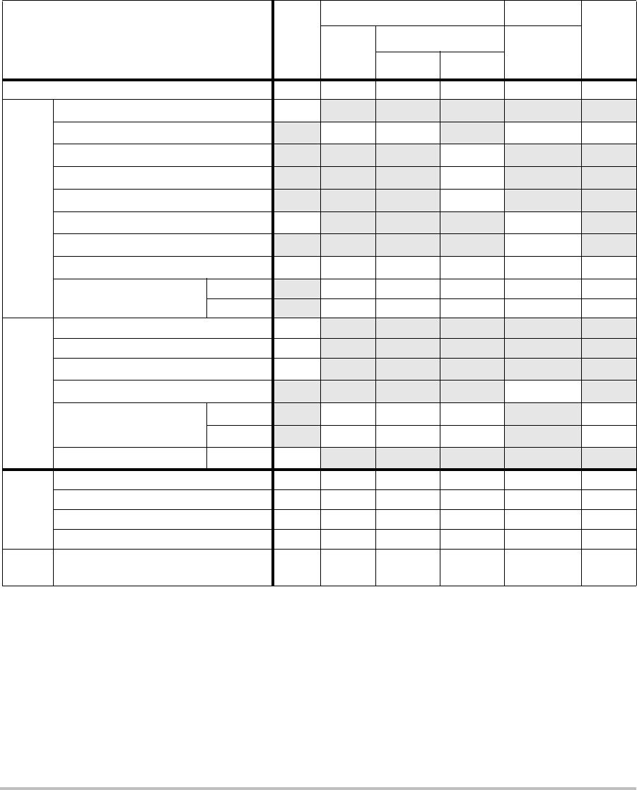
72
(a) This index is not required for this operating mode; value is <1.
(b) This transducer is not intended for transcranial or neonatal cephalic uses.
#No data are reported for this operating condition since the global maximum index value is not reported for
the reason listed. (Reference Global Maximum Index Value line.)
— Data are not applicable for this transducer/mode.
Table 8: Transducer Model: C11x/8-5 Operating Mode: CPD/Color
Index Label M.I.
TIS TIB
TIC
Scan
Non-scan
Non-scan
Aaprt≤1A
aprt>1
Global Maximum Index Value (a) (a) — — — 1.2
Associated Acoustic
Parameter
pr.3 (MPa) #
W0(mW) #— —40.50
min of [W.3(z1),ITA.3(z1)] (mW) —
z1(cm) —
zbp (cm) —
zsp (cm) #—
deq(zsp)(cm) —
fc(MHz) ## — — — 4.38
Dim of Aaprt X(cm) # — — — 0.36
Y(cm) #—— —0.5
Other Information
PD (μsec) #
PRF (Hz) #
pr@PIImax (MPa) #
deq@Pllmax (cm) —
Focal Length FLx (cm) #—— 1.56
FLy (cm) #—— 2.5
IPA.3@MImax (W/cm2)#
Operating
Control
Conditions
Control 1: Mode CPD
Control 2: Exam Type Vas
Control 3: PRF 2841
Control 4: Optimization/Depth Med/2.0
Control 5: Color Box
Position/ Size
Top/
Short
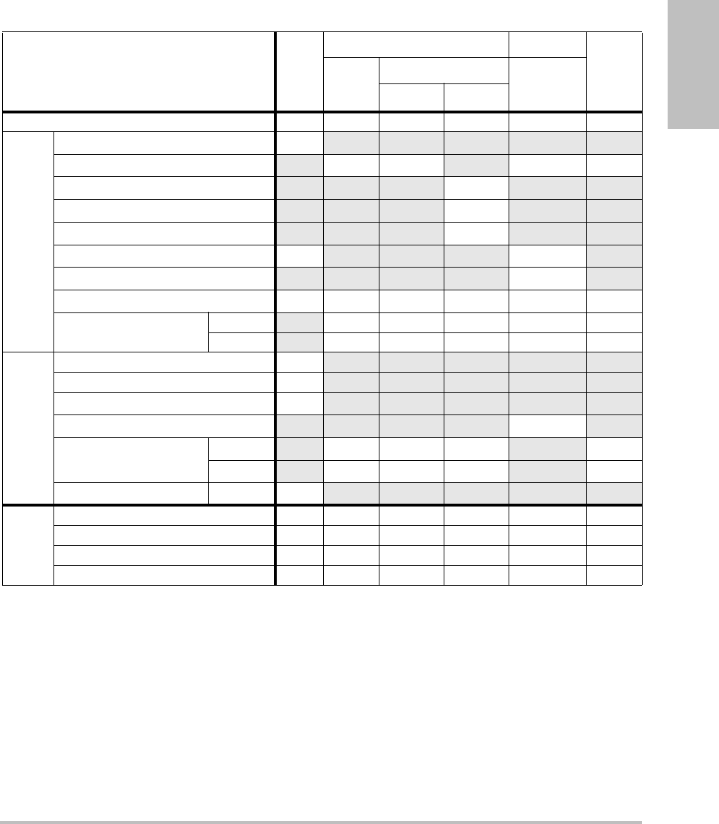
Chapter 6: Safety 73
Safety
(a) This index is not required for this operating mode; value is <1.
(b) This transducer is not intended for transcranial or neonatal cephalic uses.
#No data are reported for this operating condition since the global maximum index value is not reported for
the reason listed. (Reference Global Maximum Index Value line.)
— Data are not applicable for this transducer/mode.
Table 9: Transducer Model: C60x/5-2 Operating Mode: 2D
Index Label M.I.
TIS TIB
TIC
Scan
Non-scan
Non-scan
Aaprt≤1A
aprt>1
Global Maximum Index Value 1.0 (a) — — — (b)
Associated Acoustic
Parameter
pr.3 (MPa) 1.59
W0(mW) #— —#
min of [W.3(z1),ITA.3(z1)] (mW) —
z1(cm) —
zbp (cm) —
zsp (cm) 5.3 —
deq(zsp)(cm) —
fc(MHz) 2.86 # — — — #
Dim of Aaprt X(cm) #—— — #
Y(cm) #—— — #
Other Information
PD (μsec) 0.579
PRF (Hz) 7923
pr@PIImax (MPa) 2.679
deq@Pllmax (cm) —
Focal Length FLx (cm) #—— #
FLy (cm) #—— #
IPA.3@MImax (W/cm2)197.7
Operating
Control
Conditions
Control 1: Exam Type Any
Control 2: Optimization Pen
Control 3: Depth 6.6 cm
Control 4: THI On
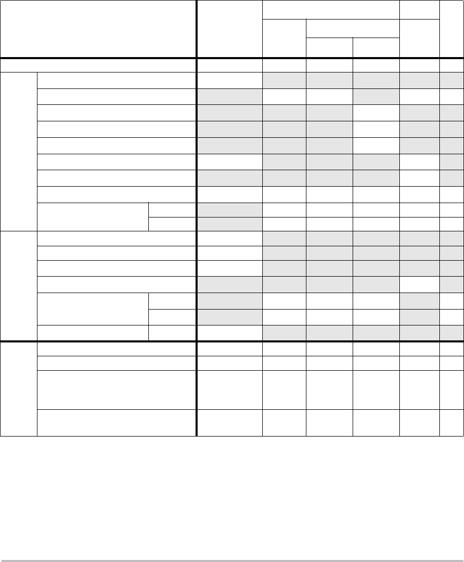
74
(a) This index is not required for this operating mode; value is <1.
(b) This transducer is not intended for transcranial or neonatal cephalic uses.
#No data are reported for this operating condition since the global maximum index value is not reported for
the reason listed. (Reference Global Maximum Index Value line.)
— Data are not applicable for this transducer/mode.
Table 10: Transducer Model: HFL38x/13-6 Operating Mode: CPD/Color
Index Label M.I.
TIS TIB
TIC
Scan
Non-scan Non-
scan
Aaprt≤1A
aprt>1
Global Maximum Index Value 1.1 1.0 — — — (b)
Associated Acoustic
Parameter
pr.3 (MPa) 2.556
W0(mW) 53.49 — —#
min of [W.3(z1),ITA.3(z1)] (mW) —
z1(cm) —
zbp (cm) —
zsp (cm) 1.2 —
deq(zsp)(cm) —
fc(MHz) 5.328 5.324 — — — #
Dim of Aaprt X(cm) 0.44 — — — #
Y(cm) 0.4 — — — #
Other Information
PD (μsec) 0.525
PRF (Hz) 2597
pr@PIImax (MPa) 3.187
deq@Pllmax (cm) —
Focal Length FLx (cm) 1.32 — — #
FLy (cm) 2.5 — — #
IPA.3@MImax (W/cm2)325.5
Operating
Control
Conditions
Control 1: Mode Color Color
Control 2: Exam Type Any Any
Control 3: Optimization/Depth/PRF Low/3.3 cm/
393
Med/
2.7 cm/
1938
Control 4: Color Box Position/Size Any Top/
Short

Chapter 6: Safety 75
Safety
(a) This index is not required for this operating mode; value is <1.
(b) This transducer is not intended for transcranial or neonatal cephalic uses.
#No data are reported for this operating condition since the global maximum index value is not reported for
the reason listed. (Reference Global Maximum Index Value line.)
— Data are not applicable for this transducer/mode.
Table 11: Transducer Model: L38x/10-5 Operating Mode: CPD/Color
Index Label M.I.
TIS TIB
TIC
Scan
Non-scan
Non-scan
Aaprt≤1A
aprt>1
Global Maximum Index Value 1.3 1.0 — — — (b)
Associated Acoustic
Parameter
pr.3 (MPa) 2.89
W0(mW) 64.88 — —#
min of [W.3(z1),ITA.3(z1)] (mW) —
z1(cm) —
zbp (cm) —
zsp (cm) 1.1 —
deq(zsp)(cm) —
fc(MHz) 4.91 4.91 — — — #
Dim of Aaprt X(cm) 0.54 — — — #
Y(cm) 0.4 — — — #
Other Information
PD (μsec) 0.529
PRF (Hz) 9547
pr@PIImax (MPa) 3.48
deq@Pllmax (cm) —
Focal Length FLx (cm) 1.5 — — #
FLy (cm) 2.5 — — #
IPA.3@MImax (W/cm2)439.3
Operating
Control
Conditions
Control 1: Mode Color CPD
Control 2: Exam Type Any Bre
Control 3: PRF 331 2137
Control 4: Optimization/Depth Any/3.1 Med/3.1
Control 5: Color Box Position/Size Any Def/
Def/Def
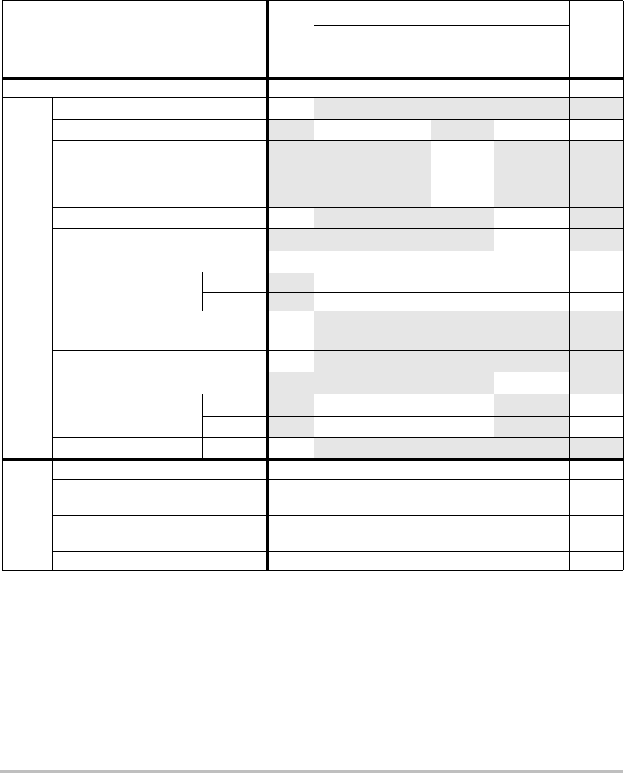
76
(a) This index is not required for this operating mode; value is <1.
(b) This transducer is not intended for transcranial or neonatal cephalic uses.
#No data are reported for this operating condition since the global maximum index value is not reported for
the reason listed. (Reference Global Maximum Index Value line.)
— Data are not applicable for this transducer/mode.
Table 12: Transducer Model: P21x/5-1 Operating Mode: 2D
Index Label M.I.
TIS TIB
TIC
Scan
Non-scan
Non-scan
Aaprt≤1A
aprt>1
Global Maximum Index Value 1.3 1.1 — — — (b)
Associated Acoustic
Parameter
pr.3 (MPa) 1.83
W0(mW) 122.87 — —#
min of [W.3(z1),ITA.3(z1)] (mW) —
z1(cm) —
zbp (cm) —
zsp (cm) 5.1 —
deq(zsp)(cm) —
fc(MHz) 1.84 1.88 — — — #
Dim of Aaprt X(cm) 0.590 — — — #
Y(cm) 1.3 — — — #
Other Information
PD (μsec) 0.963
PRF (Hz) 4421
pr@PIImax (MPa) 2.574
deq@Pllmax (cm) —
Focal Length FLx (cm) 1.55 — — #
FLy (cm) 5.5 — — #
IPA.3@MImax (W/cm2)209.0
Operating
Control
Conditions
Control 1: Exam Type Card Abd/OB
Control 2: Optimization Pen/
Gen Any
Control 3: Depth 4.7/7.6
cm 4.7
Control 4: THI On On
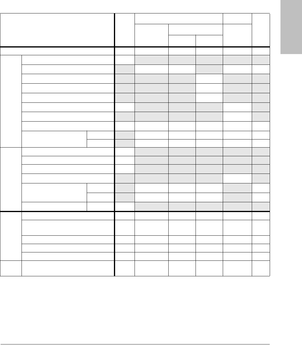
Chapter 6: Safety 77
Safety
(a) This index is not required for this operating mode; value is <1.
(b) This transducer is not intended for transcranial or neonatal cephalic uses.
#No data are reported for this operating condition since the global maximum index value is not reported for
the reason listed. (Reference Global Maximum Index Value line.)
— Data are not applicable for this transducer/mode.
Table 13: Transducer Model: P21x/5-1 Operating Mode: CPD/Color
Index Label M.I.
TIS TIB
TIC
Scan
Non-scan
Non-scan
Aaprt≤1A
aprt>1
Global Maximum Index Value 1.5 1.3 — — — (b)
Associated Acoustic
Parameter
pr.3 (MPa) 2.19
W0(mW) 136.91 — —#
min of [W.3(z1),ITA.3(z1)] (mW) —
z1(cm) —
zbp (cm) —
zsp (cm) 4.5 —
deq(zsp)(cm) —
fc(MHz) 2.15 2.16 — — — #
Dim of Aaprt X(cm) 0.918 — — — #
Y(cm) 1.3 — — — #
Other Information
PD (μsec) 1.20
PRF (Hz) 1063
pr@PIImax (MPa) 2.574
deq@Pllmax (cm) —
Focal Length FLx (cm) 3.68 — — #
FLy (cm) 5.5 — — #
IPA.3@MImax (W/cm2)330.4
Operating
Control
Conditions
Control 1: Mode Color CPD
Control 2: Exam Type Abd/
OB OB
Control 3: PRF/Depth 300/10 850/7.5
Control 4: Color Optimization Any Med
Control 5: THI On Off
Control 6: Color Box Size Any Short and
Narrow

78
Terms used in the acoustic output tables
Table 14: Acoustic Output Terms and Definitions
Term Definition
ISPTA.3 Derated spatial peak, temporal average intensity in units of milliwatts/cm2.
TI type Applicable thermal index for the transducer, imaging mode, and exam type.
TI value Thermal index value for the transducer, imaging mode, and exam type.
MI Mechanical index.
Ipa.3@MImax Derated pulse average intensity at the maximum MI in units of W/cm2.
TIS (Soft tissue thermal index) is a thermal index related to soft tissues. TIS scan is
the soft tissue thermal index in an auto-scanning mode. TIS non-scan is the
soft tissue thermal index in the non-autoscanning mode.
TIB (Bone thermal index) is a thermal index for applications in which the
ultrasound beam passes through soft tissue and a focal region is in the
immediate vicinity of bone. TIB non-scan is the bone thermal index in the
non-autoscanning mode.
TIC (Cranial bone thermal index) is the thermal index for applications in which
the ultrasound beam passes through bone near the beam entrance into the
body.
Aaprt Area of the active aperture measured in cm2.
Pr.3 Derated peak rarefactional pressure associated with the transmit pattern
giving rise to the value reported under MI (Megapascals).
Wo Ultrasonic power, except for TISscan, in which case it is the ultrasonic power
passing through a one centimeter window in units of milliwatts.
W.3(z1)Derated ultrasonic power at axial distance z1 in units of milliwatts.
ISPTA.3(z1)Derated spatial-peak temporal-average intensity at axial distance z1
(milliwatts per square centimeter).
z1Axial distance corresponding to the location of maximum [min(W.3(z), ITA.3(z)
x 1 cm2)], where z > zbp in centimeters.
zbp 1.69 in centimeters.
zsp For MI, the axial distance at which pr.3 is measured. For TIB, the axial distance
at which TIB is a global maximum (for example, zsp = zb.3) in centimeters.
Aaprt()

Chapter 6: Safety 79
Safety
Acoustic measurement precision and uncertainty
Alltableentrieshavebeenobtainedatthesameoperatingconditionsthatgiverisetothe
maximumindexvalueinthefirstcolumnofthetable.Measurementprecisionanduncertainty
forpower,pressure,intensity,andotherquantitiesthatareusedtoderivethevaluesinthe
acousticoutputtableareshowninthetablebelow.InaccordancewithSection 6.4oftheOutput
DisplayStandard,thefollowingmeasurementprecisionanduncertaintyvaluesare
determinedbymakingrepeatmeasurementsandstatingthestandarddeviationasa
percentage.
deq(z) Equivalent beam diameter as a function of axial distance z, and is equal to
, where ITA(z) is the temporal-average intensity as a
function of z in centimeters.
fc Center frequency in MHz.
Dim. of Aaprt Active aperture dimensions for the azimuthal (x) and elevational (y) planes in
centimeters.
PD Pulse duration (microseconds) associated with the transmit pattern giving
rise to the reported value of MI.
PRF Pulse repetition frequency associated with the transmit pattern giving rise to
the reported value of MI in Hertz.
pr@PIImax Peak rarefactional pressure at the point where the free-field, spatial-peak
pulse intensity integral is a maximum in Megapascals.
deq@PIImax Equivalent beam diameter at the point where the free-field, spatial-peak
pulse intensity integral is a maximum in centimeters.
FL Focal length, or azimuthal (x) and elevational (y) lengths, if different
measured in centimeters.
Table 14: Acoustic Output Terms and Definitions (Continued)
Term Definition
4π()⁄()Wo()ITA z()()⁄()
Table 15: Acoustic Measurement Precision and Uncertainty
Quantity Precision
(% of standard deviation)
Uncertainty
(95% confidence)
Pr 1.9% +11.2%
Pr.3 1.9% +12.2%
Wo 3.4% +10%
fc 0.1% +4.7%
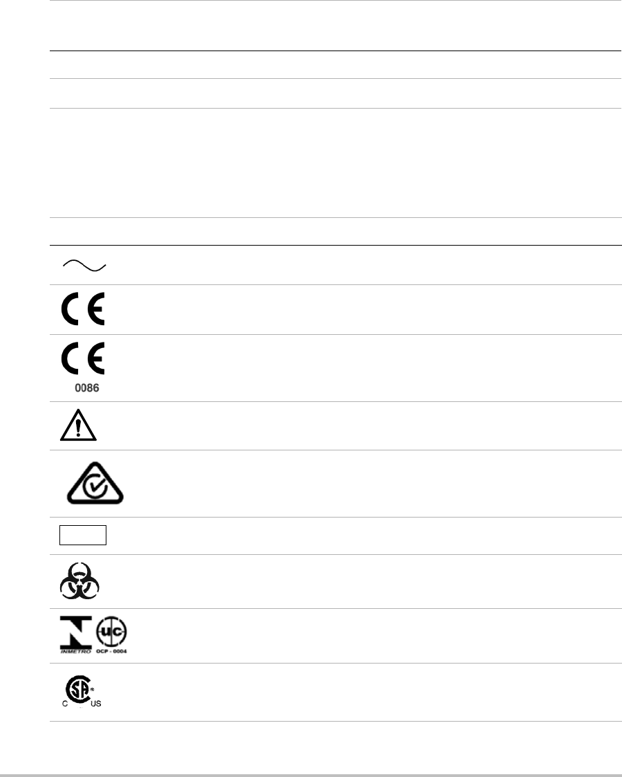
80
Labeling symbols
Thefollowingsymbolsareusedontheproducts,packaging,andcontainers.
PII 3.2% +12.5 to -16.8%
PII.3 3.2% +13.47 to -17.5%
Table 15: Acoustic Measurement Precision and Uncertainty (Continued)
Quantity Precision
(% of standard deviation)
Uncertainty
(95% confidence)
Table 16: Labeling Symbols
Symbol Definition
Alternating Current (AC)
Class 1 device indicating manufacturer’s declaration of conformance with
Annex VII of 93/42/EEC
Class 1 device requiring verification by the Notified Body of sterilization or
measurement features, or to a Class IIa, IIb, or III device requiring verification or
auditing by the Notified Body to applicable Annex(es) of 93/42/EEC
Attention, see the user guide
Device complies with relevant Australian regulations for electronic devices.
Batch code, date code, or lot code type of control number
Biological risk
Device complies with relevant Brazilian regulations for electro-medical devices.
Canadian Standards Association. The “C” and “US” indicators next to this mark
signify that the product has been evaluated to the applicable CSA and ANSI/UL
Standards, for use in Canada and the US, respectively.
LOT
Chapter 6: Safety 81
Safety
Catalog number
Collect separately from other household waste (see European Commission
Directive 93/86/EEC). Refer to local regulations for disposal.
Contents sterilized using ethylene oxide process.
Corrugated recycle
Dangerous voltage
Date of manufacture
Direct Current (DC)
Do not get wet.
Do not stack over 2 high.
Do not stack over 5 high.
Do not stack over 10 high.
Electrostatic sensitive devices
Device complies with relevant FCC regulations for electronic devices.
Table 16: Labeling Symbols (Continued)
Symbol Definition
REF
STERILE EO
82
Fragile
Gel sterilized by radiation.
Hot
Indoor use only
Device emits a static (DC) magnetic field.
Non-ionizing radiation
Paper recycle
Serial number type of control number
Storage temperature conditions
Submersible. Protected against the effects of temporary immersion.
Water-Tight Equipment. Protected against the effects of extended immersion.
Handle transducer with care.
Type BF patient applied part
(B = body, F = floating applied part)
Underwriter’s Laboratories labeling
Table 16: Labeling Symbols (Continued)
Symbol Definition
STERILE RGEL
SN
Chapter 6: Safety 83
Safety
Pollution Control Logo. (Applies to all parts/products listed in the China RoHS
disclosure table. May not appear on the exterior of some parts/products
because of space limitations.)
China Compulsory Certificate mark (“CCC Mark”). A compulsory safety mark for
compliance to Chinese national standards for many products sold in the
People’s Republic of China.
Contains mercury. (Applies to the LCD and may apply to other components in
the ultrasound system.)
WARNING:
Connect Only
Accessories and
Peripherals
Recommended by
SonoSite
WARNING: Connect Only
Accessories and Peripherals
Recommended by SonoSite
Table 16: Labeling Symbols (Continued)
Symbol Definition

84

Chapter 7: Specifications 85
Specifications
Chapter 7: Specifications
Thischaptercontainssystemandaccessoryspecificationsandstandards.The
specificationsforrecommendedperipheralsareinthemanufacturers’instructions.
Supported transducers
Imaging modes
Images and clips storage
Internalstorage:Thenumberofimagesandclipsyoucansavedependsonimagingmode
andfileformat.
Accessories
Thefollowingitemsareeitherincludedwithoravailableforuseontheultrasoundsystem.
•Battery
•BiopsyGuide
• NeedleGuide
•Powersupply
•SystemACpowercord(10ft/3.1m)
•SSeriesstand
• C11x/8‐5MHz(6ft/1.8m)
• C60x/5‐2MHz(5.5ft/1.7m)
• HFL38x/13‐6MHz(5.6ft/1.7m)
•ICTx/8‐5MHz(5.5ft/1.7m)/
• L25x/13‐6MHz(7.5ft/2.3m)
• L38x/10‐5MHz(5.5ft/1.7m)
•P21x/5‐1MHz(6ft/1.8m)
•2D(256grayshades)
• ColorpowerDoppler(CPD)(256
colors)
• ColorDoppler(Color)(256colors)

86
Peripherals
Peripheralsincludemedicalgrade(conformingtoEN60601‐1requirements)and
non‐medicalgrade(commercial)products.Manufacturer’sinstructionsaccompanyeach
peripheral.
Temperature and humidity limits
Note: Thetemperature,pressure,andhumiditylimitsapplyonlytotheultrasoundsystem,
transducers,andbattery.
Medical
grade
• Black-and-white printer
Recommended sources for printer paper: Contact Sony at 800-686-7669
or www.sony.com/professional to order supplies or to find the local
distributor.
•DVD recorder
Non-medical
grade
• Kensington Security Cable
• USB keyboard
Table 1: Operating Limits
System Battery Transducer
10–40°C (50–104°F),
15–95% R.H.
700 to 1060hPa (0.7 to
1.05 ATM)
10–40°C (50–104°F),
15–95% R.H.
700 to 1060hPa (0.7 to
1.05 ATM)
10–40°C (50–104°F),
15–95% R.H.
Table 2: Shipping and Storage Limits
System without
Battery Battery Transducer
-35–65°C (-31–149°F),
15–95% R.H.
500 to 1060hPa (0.5 to
1.05 ATM)
-20–60°C (-4–140°F),
15–95% R.H.*
500 to 1060hPa (0.5 to
1.05 ATM)
-35–65°C (-31–149°F),
15–95% R.H.
* For storage longer than 30 days, store at or below room temperature.

Chapter 7: Specifications 87
Specifications
Electrical
Battery
Thebatterycomprisessixlithium‐ioncellspluselectronics,atemperaturesensor,and
batterycontacts.
Runtimeisuptotwo hours,dependingonimagingmodeanddisplaybrightness.
Electromechanical safety standards
EN60601‐1:1997,EuropeanNorm,MedicalElectricalEquipment–Part 1.General
RequirementsforSafety.
EN60601‐1‐1:2001,EuropeanNorm,MedicalElectricalEquipment–Part1.General
RequirementsforSafety–Section1‐1.CollateralStandard.SafetyRequirementsforMedical
ElectricalSystems.
EN60601‐2‐37:2001+AmendmentA1:2005,EuropeanNorm,Particularrequirementsfor
thesafetyofultrasonicmedicaldiagnosticandmonitoringequipment.
CAN/CSAC22.2,No.601.1‐M90,CanadianStandardsAssociation,MedicalElectrical
Equipment–Part1.GeneralRequirementsforSafety(includingCSA601.1Supplement
1:1994andCSA601.1Amendment2:1998).
CEI/IEC61157:1992,InternationalElectrotechnicalCommission,Requirementsforthe
DeclarationoftheAcousticOutputofMedicalDiagnosticUltrasonicEquipment.
UL60601‐1(1stEdition),UnderwritersLaboratories,MedicalElectricalEquipment‐Part 1:
GeneralRequirementsforSafety.
EMC standards classification
EN60601‐1‐2:2001,EuropeanNorm,MedicalElectricalEquipment.GeneralRequirements
forSafety‐CollateralStandard.ElectromagneticCompatibility.RequirementsandTests.
CISPR11:2004,InternationalElectrotechnicalCommission,InternationalSpecial
CommitteeonRadioInterference.Industrial,Scientific,andMedical(ISM)
Radio‐FrequencyEquipmentElectromagneticDisturbanceCharacteristics‐Limitsand
MethodsofMeasurement.
PowerSupplyInput 100‐240VAC,50/60Hz,2.0AMax@100VAC
PowerSupplyOutput#1 15VDC,5.0AMax
PowerSupplyOutput#2 12VDC,2.3AMax

88
TheClassificationfortheultrasoundsystem,stand,accessories,andperipheralswhen
configuredtogetheris:Group1,ClassA.
Airborne equipment standards
RTCA/DO‐160E:2004,RadioTechnicalCommissionforAeronautics,Environmental
ConditionsandTestProceduresforAirborneEquipment,Section 21.0EmissionofRadio
FrequencyEnergy,Category B.
HIPAA standard
TheHealthInsuranceandPortabilityandAccountabilityAct,Pub.L.No.104‐191(1996).
45CFR160,GeneralAdministrativeRequirements.
45CFR164,SecurityandPrivacy.

Glossary 89
Glossary
Glossary
Terms
Forultrasoundtermsnotincludedinthisglossary,refertoRecommendedUltrasound
Terminology,SecondEdition,publishedin1997bytheAmericanInstituteofUltrasoundin
Medicine(AIUM).
as low as reasonably
achievable (ALARA)
The guiding principle of ultrasound use, which states that you should
keep patient exposure to ultrasound energy as low as reasonably
achievable for diagnostic results.
curved array
transducer
Identified by the letter C (curved or curvilinear) and a number (60). The
number corresponds to the radius of curvature of the array expressed
in millimeters. The transducer elements are electrically configured to
control the characteristics and direction of the acoustic beam. For
example, C15, C60e.
depth Refers to the depth of the display. A constant speed of sound of
1538.5 meters/second is assumed in the calculation of echo position in
the image.
in situ In the natural or original position.
LCD liquid crystal display
linear array
transducer
Identified by the letter L (linear) and a number (38). The number
corresponds to the radius of width of the array expressed in
millimeters. The transducer elements are electrically configured to
control the characteristics and direction of the acoustic beam. For
example, L38.
mechanical index
(MI)
An indication of the likelihood of mechanical bioeffects occurring: the
higher the MI, the greater the likelihood of mechanical bioeffects. See
Chapter 6, “Safety,” for a more complete description of MI.
MI/TI See mechanical index (MI) and thermal index (TI).
NTSC National Television Standards Committee. A video format setting. See
also PAL.
PAL Phase Alternating Line. A video format setting. See also NTSC.
phased array A transducer designed primarily for cardiac scanning. Forms a sector
image by electronically steering the beam direction and focus.

90
skinline A depth on the display that corresponds to the skin/transducer
interface.
SonoHD™ imaging
technology
A subset of the 2D imaging mode in which the 2D image is enhanced
by reducing speckle noise artifact at tissue margins and improving
contrast resolution by reducing artifacts and improving visualization of
texture patterns within the image.
SonoMB technology A subset of the 2D imaging mode in which the 2D image is enhanced
by looking at a target from three angles and then merging or averaging
the scanned data together to improve overall image quality and, in
parallel, reducing noise and artifacts.
thermal index (TI) The ratio of total acoustic power to the acoustic power required to raise
tissue temperature by 1°C under defined assumptions. See Chapter 6,
“Safety,” for a more complete description of TI.
TIB (bone thermal
index)
A thermal index for applications in which the ultrasound beam passes
through soft tissue and a focal region is in the immediate vicinity of
bone.
TIC (cranial bone
thermal index)
A thermal index for applications in which the ultrasound beam passes
through bone near the beam entrance into the body.
TIS (soft tissue
thermal index)
A thermal index related to soft tissues.
Tissue Harmonic
Imaging
Transmits at one frequency and receives at a higher harmonic
frequency to reduce noise and clutter and improve resolution.
transducer A device that transforms one form of energy into another form of
energy. Ultrasound transducers contain piezoelectric elements, which
when excited electrically, emit acoustic energy. When the acoustic
energy is transmitted into the body, it travels until it encounters an
interface, or change in tissue properties. At the interface, an echo is
formed that returns to the transducer, where this acoustic energy is
transformed into electrical energy, processed, and displayed as
anatomical information.

Glossary 91
Glossary
Abbreviations
Abbreviations in User Interface
Abbreviation Definition
Abd Abdomen
Bre Breast
CPD Color Power Doppler
Crd Cardiac
MB SonoMB
MI Mechanical Index
Msk Musculoskeletal
Nrv Nerve
NTSC National Television Standards Committee
OB Obstetrical
S SonoHD imaging technology
SmP Small Parts
THI Tissue Harmonic Imaging
TI Thermal Index
Vas Vascular
Ven Venous

92

Index 93
Index
Index
Numerics
2D imaging 21
A
abbreviations 91
abdominal, intended uses 11
accessories list 85
acoustic measurement precision 79
acoustic output
measurement 69
tables 71
terms in tables 78
acquisition error 36
add new user 15
Administrator 14
airborne equipment standards 88
ALARA principle 62, 63, 89
alphanumeric keys 7
audio 3, 18
B
battery
charge 3
clean 43
install or remove 3
safety 56
setup 18
specifications 87
biological safety 57
Biopsy 24
brightness 21
C
cables, connect power 4
calipers 33
cardiac, intended uses 11
cautions, definition vii
cine buffer 23
clean
battery 43
LCD screen 40
system 40
transducers 41
click 9
clips
length 19
See also images and clips
color Doppler (Color) imaging 22
color power Doppler (CPD) imaging 22
Color. See color Doppler (Color) imaging
connectivity
setup 18
symbols 3
control keys 8, 9
controls
direct 63
indirect 64
receiver 64
CPD. See color power Doppler (CPD) imaging
customer assistance vii
D
date 19
default settings 13
depth
adjust 23
definition 89
marker 8, 19
disinfect
battery 43
system 40
transducers 41
disinfectants, compatibility 44
display brightness 19
distance measurements 34
DVD recorder 18, 37
E
electrical
safety 53
specifications 87
electromagnetic compatibility 58
electromechanical safety standards 87
Ellipse 35
EMC classification standards 87
equipment safety 56
error message 55

94 Index
errors
acquisition 36
algorithmic 36
measurement 36
Event log 16
exam
end 27
type and transducer 25
type, change 24
export
Event log 16
images and clips 31
USB Devices setup 20
user accounts 16
F
focal zones, optimize 22
freeze 23
G
gain
adjust 23
Auto Gain 21
grace period 38
guidance documents, related 67
Guide 24
guidelines 24
gynecology, intended uses 11
H
HIPAA standard 88
humidity limits 86
I
image quality, poor 37
images and clips
delete 31
export to USB 31
review 30
save 28
imaging modes
list of 85
transducer 25
import user accounts 16
in situ, definition 89
infertility, intended uses 11
intended uses 11
intensity
derated 69
in situ 69
water-value 69
interventional, intended uses 11
K
keyboard, on-line 9
keys 7
knobs 7
L
labeling symbols 80
language 19
LCD screen
clean 40
output 67
license key 38
login
Administrator 14
user 14
M
maintenance 39
measurements
accuracy 33, 35
area, 2D 35
circumference, 2D 35
delete 34
distance 34
edit 34
errors 36
mechanical index (MI) 67, 89
mode data 8, 19
N
needle guide 24
NTSC
definition 89
option 18
O
OB, intended uses 12
optimize 22

Index 95
Index
orientation
marker 8
option 22
output display 67
P
PAL
definition 89
option 18
password 15, 16, 17
patient header 8, 19
patient information form 27
patient list 28
PC 18
pediatric, intended uses 12
peripherals 86
power delay 18
power key 7
precision, acoustic measurement 79
preferences 19
presets 19
pressure limits 86
print 30
print control 3
printer
problem 37
setup 18
probe. See transducer
R
recording problem 37
S
safety
battery 56
clinical 57
electrical 53
electromagnetic compatibility 58
equipment 56
save 28
scanhead. See transducer
screen layout 8
security 14
serial port 18
setup pages 13
shipping specifications 86
skin line, definition 90
sleep delay 18
software license 38
SonoHD 90
SonoMB 22, 90
specifications 85
standards
airborne equipment 88
electromechanical 87
EMC classification 87
HIPAA 88
storage specifications
equipment 86
images 85
superficial, intended uses 12
symbols
connectivity 3
labeling 80
system
clean and disinfect 40
controls 7
software 1
status 8
wake up 4
T
Technical Support viii
temperature limits 86
text, enter 9
thermal index (TI) 19, 67, 90
time setup 19
tissue models 70
touchpad 9
transducer
clean and disinfect 41
connect 5
curved array 89
definition 90
disinfect 41
exam type 25
general use 10
imaging modes 25
invasive or surgical use 10
linear array 89
preparation 10
problems 37
sheath 10
specifications 85
troubleshoot 37


P07525-01
*P07525-01*