J Three Holding BU2073J Bluetooth Adaptor User Manual
J-Three International Holding Co., Ltd Bluetooth Adaptor Users Manual
Contents
- 1. Users Manual
- 2. User Guide Supplement
- 3. User Manual M Turbo
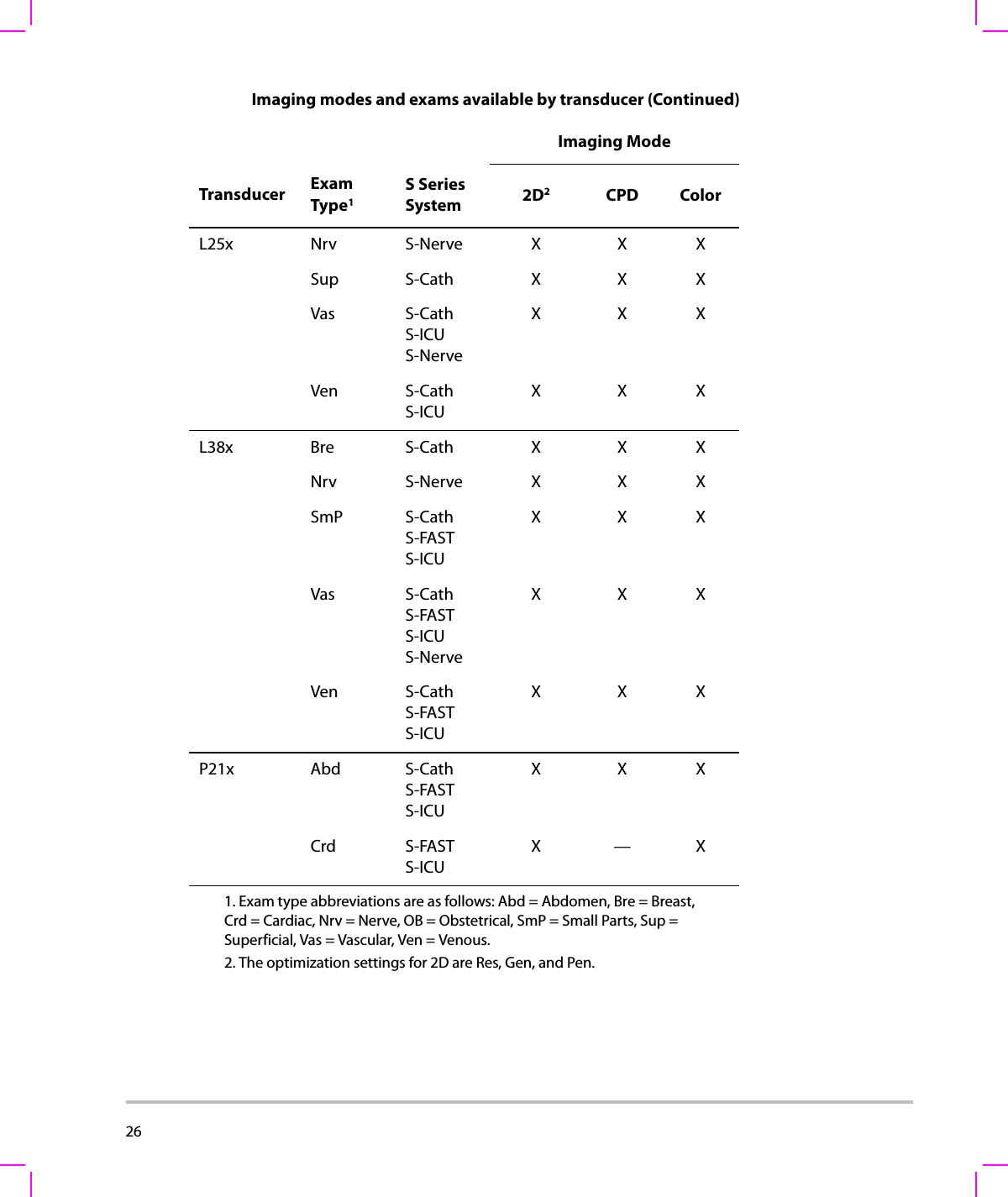
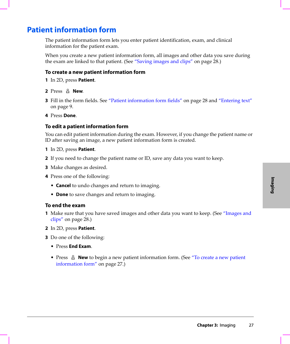
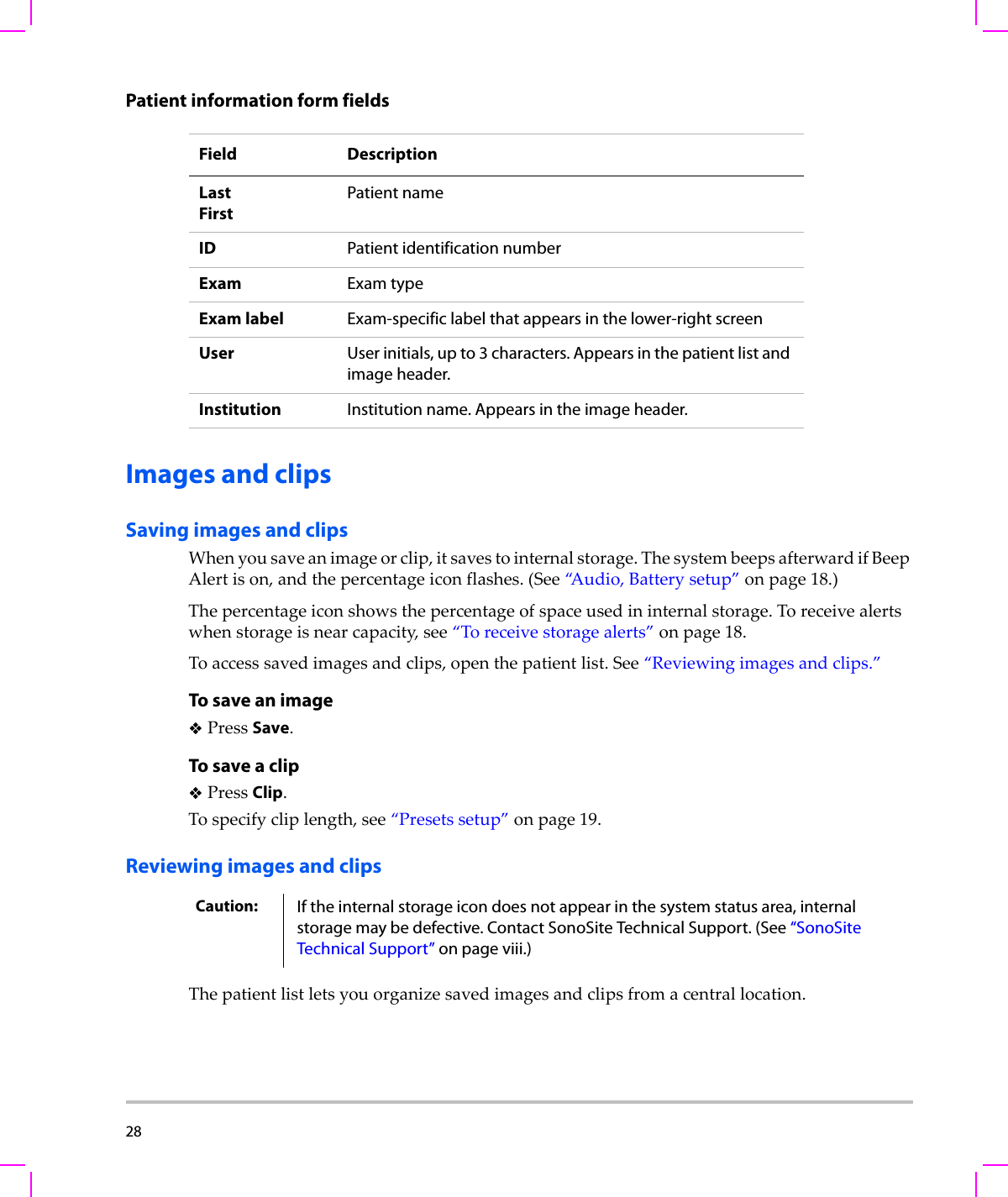
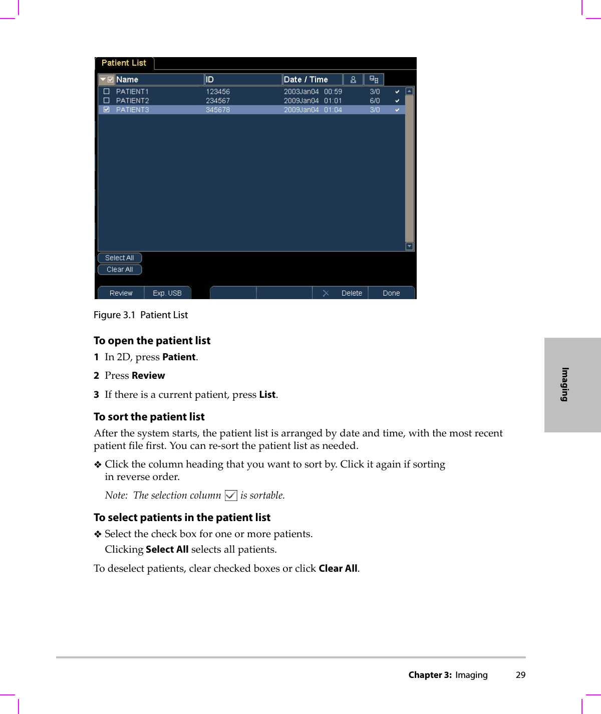
- 4. User Manual S Series
- 5. Setup Instructions
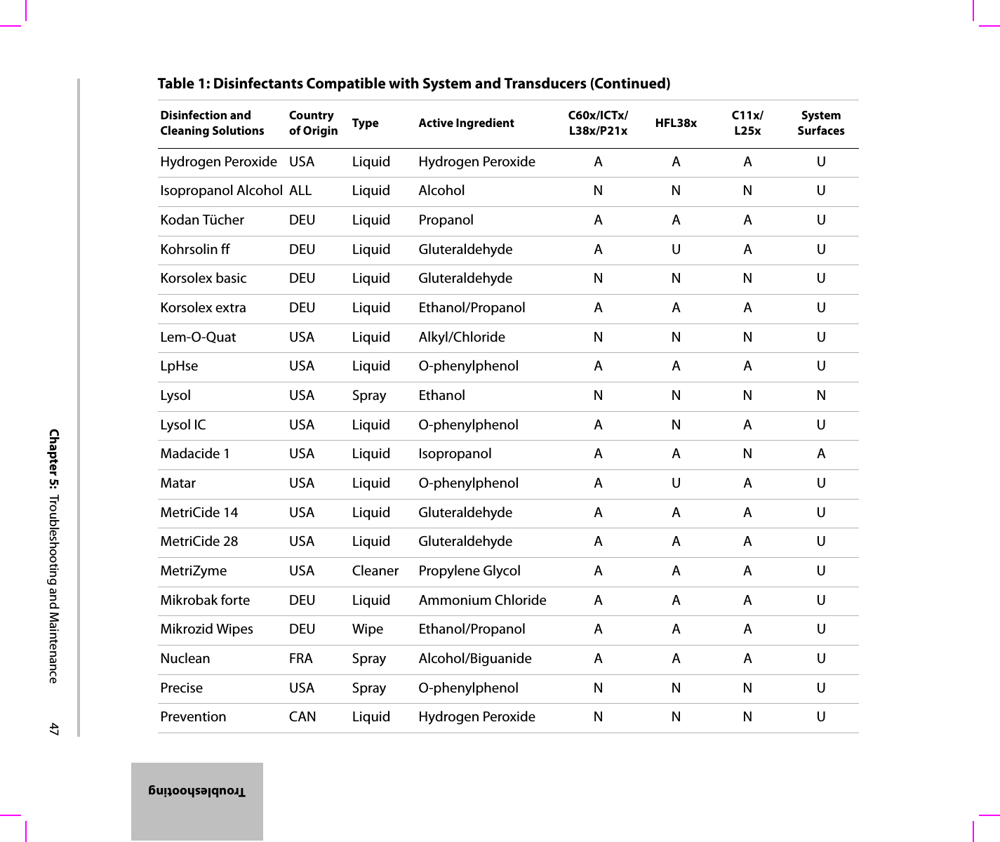
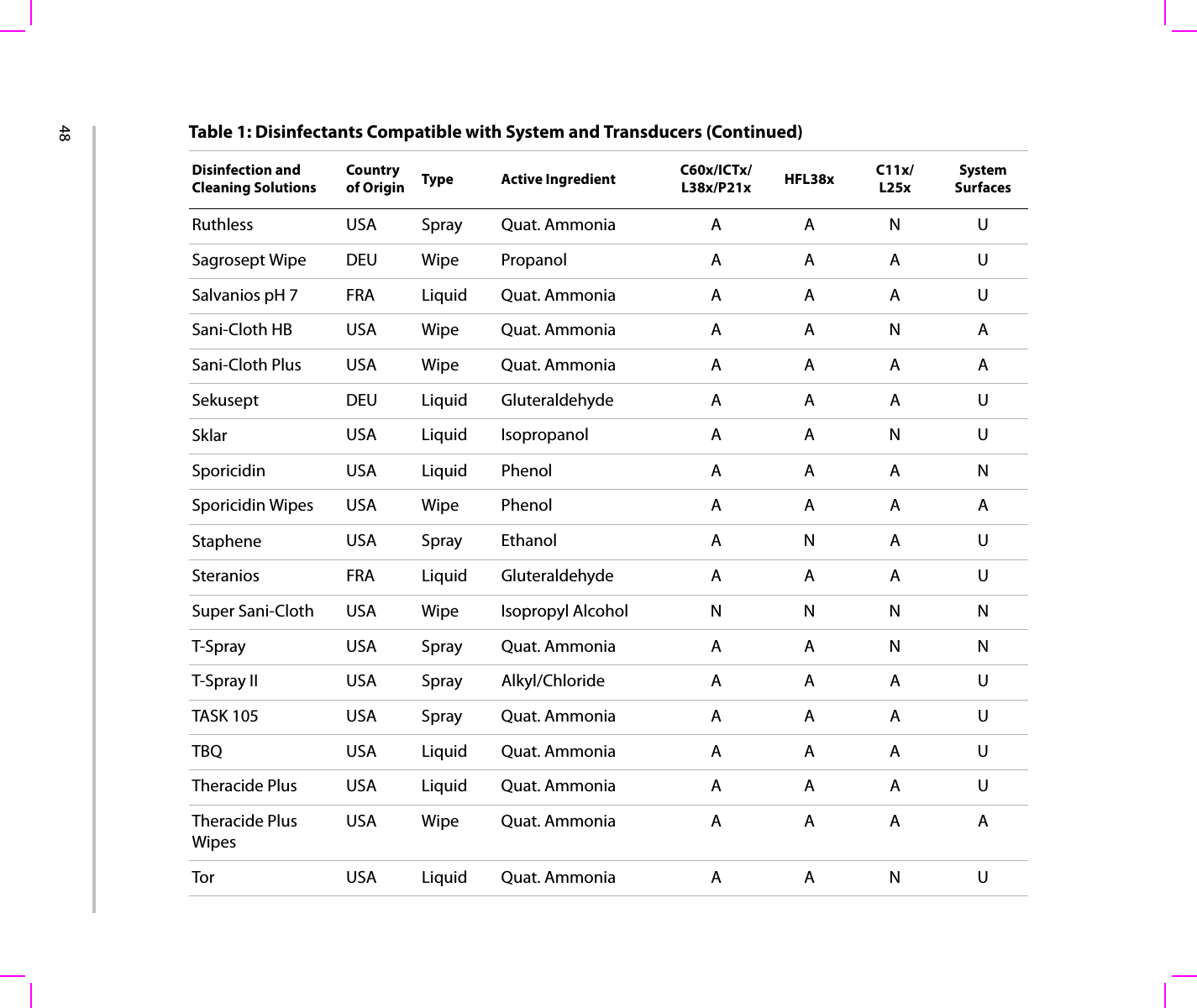
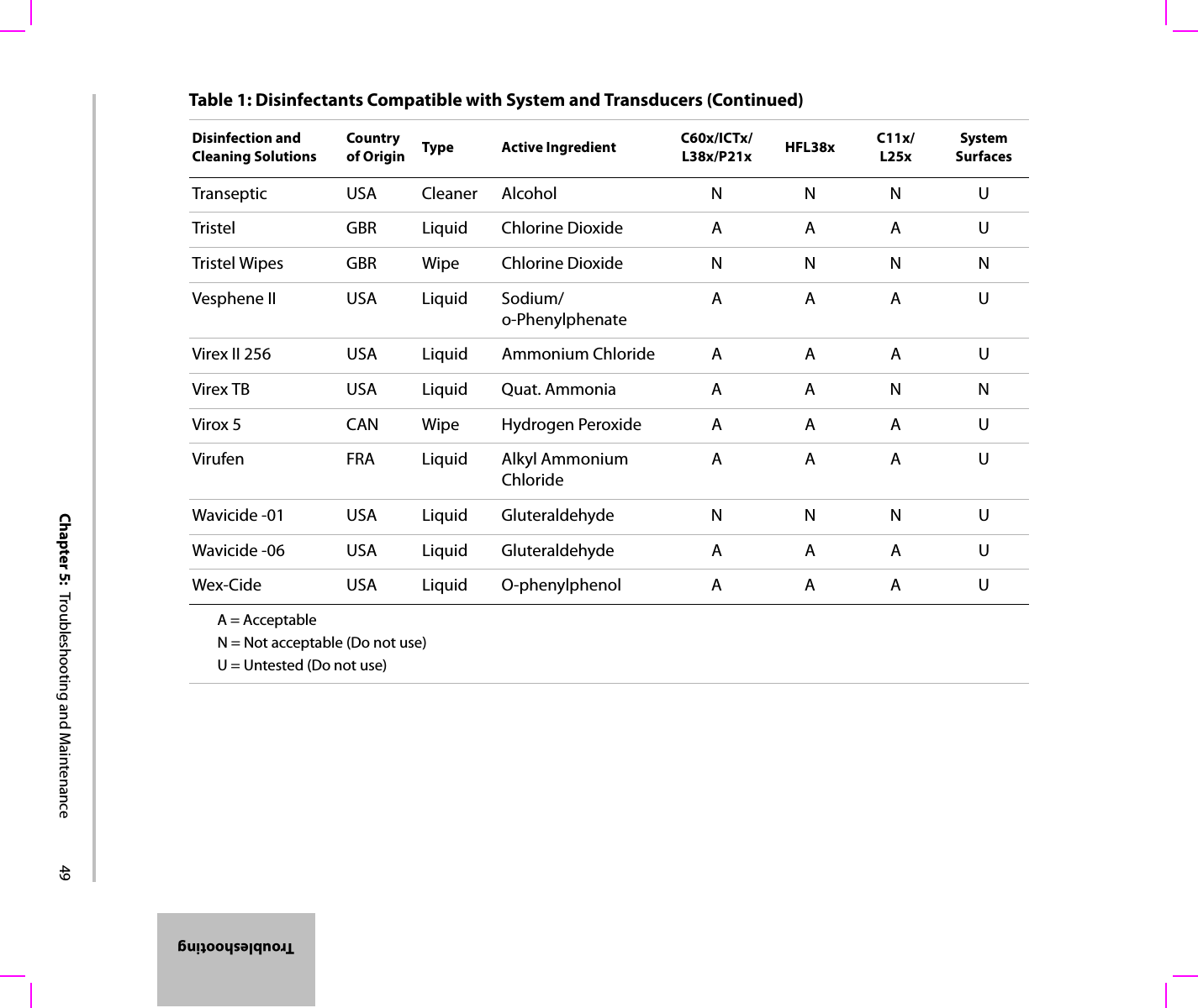
User Manual S Series
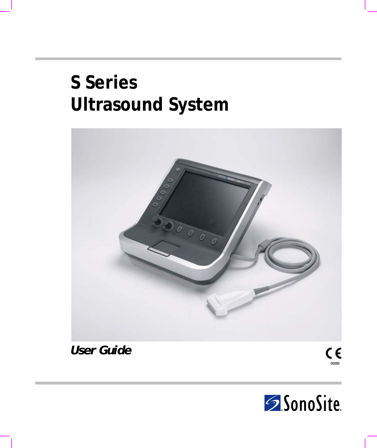
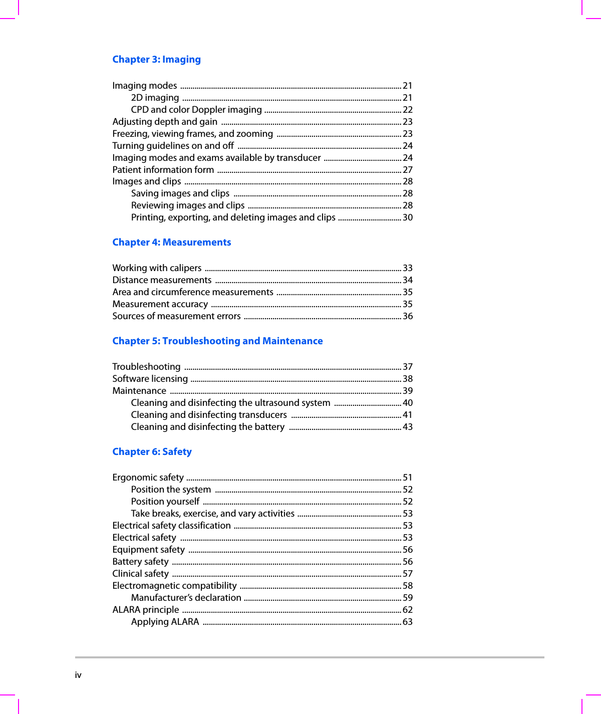

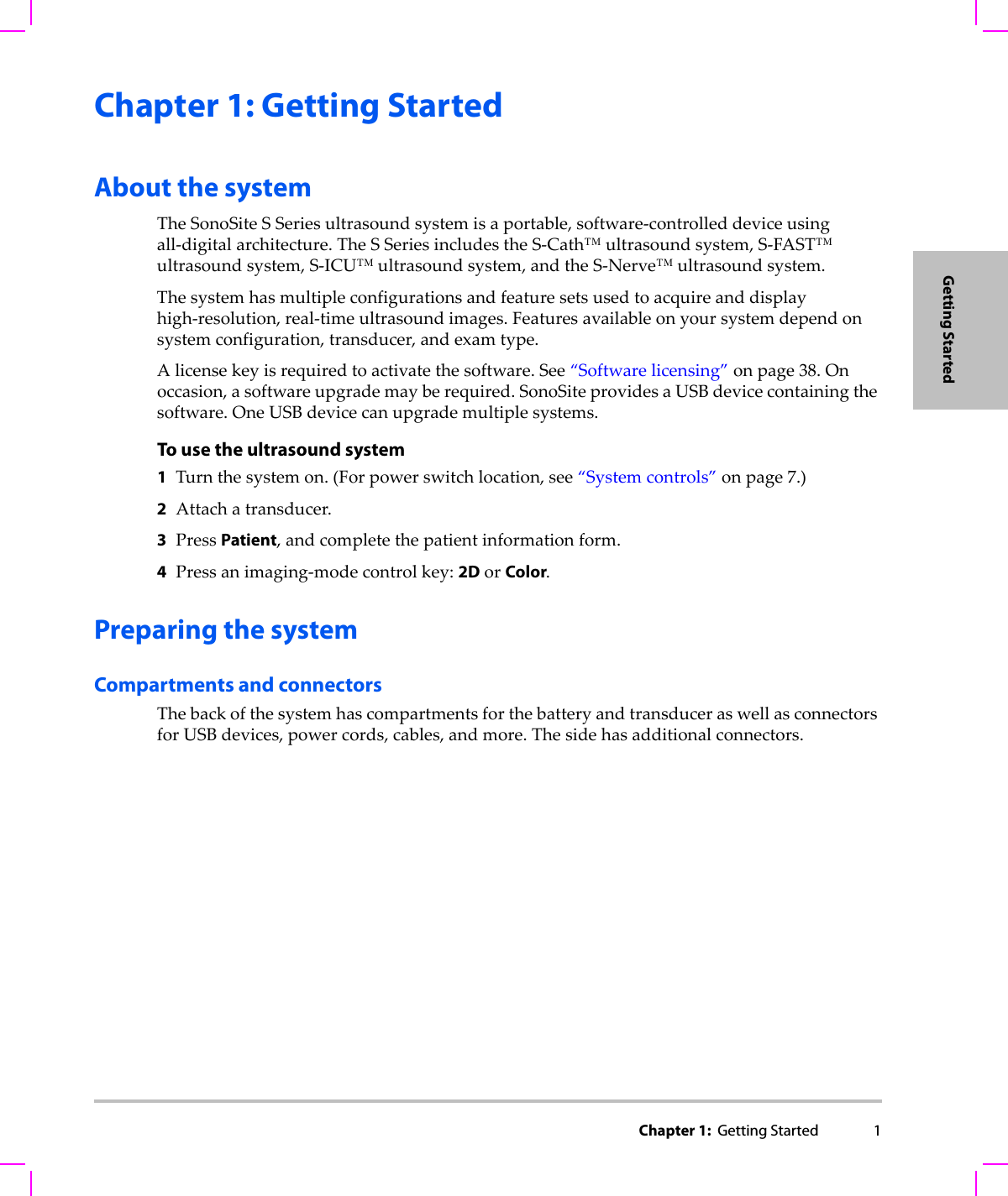
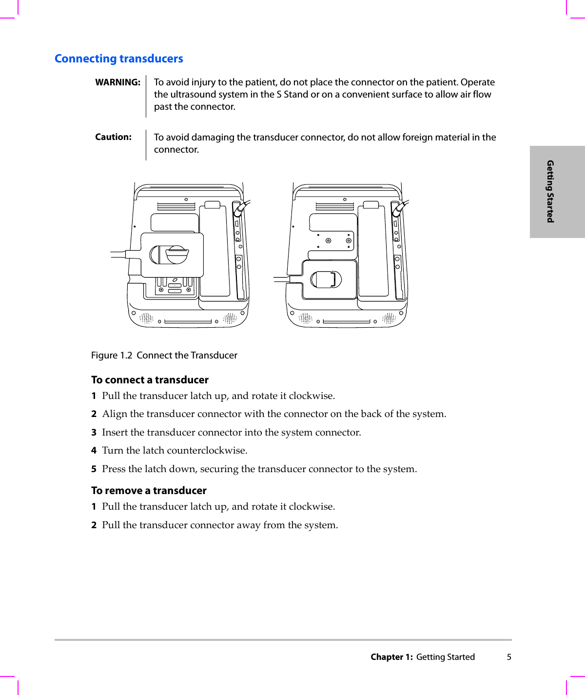
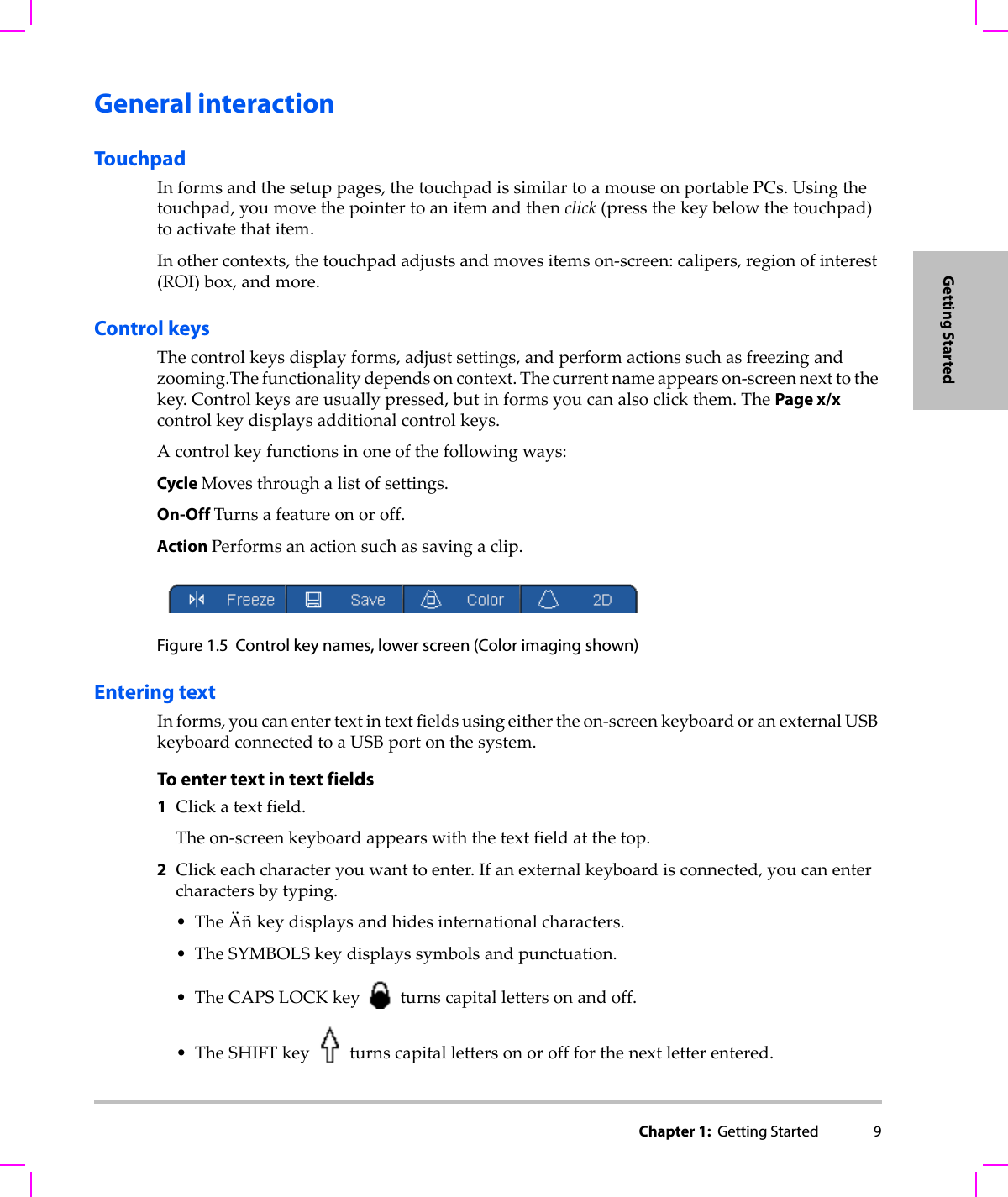
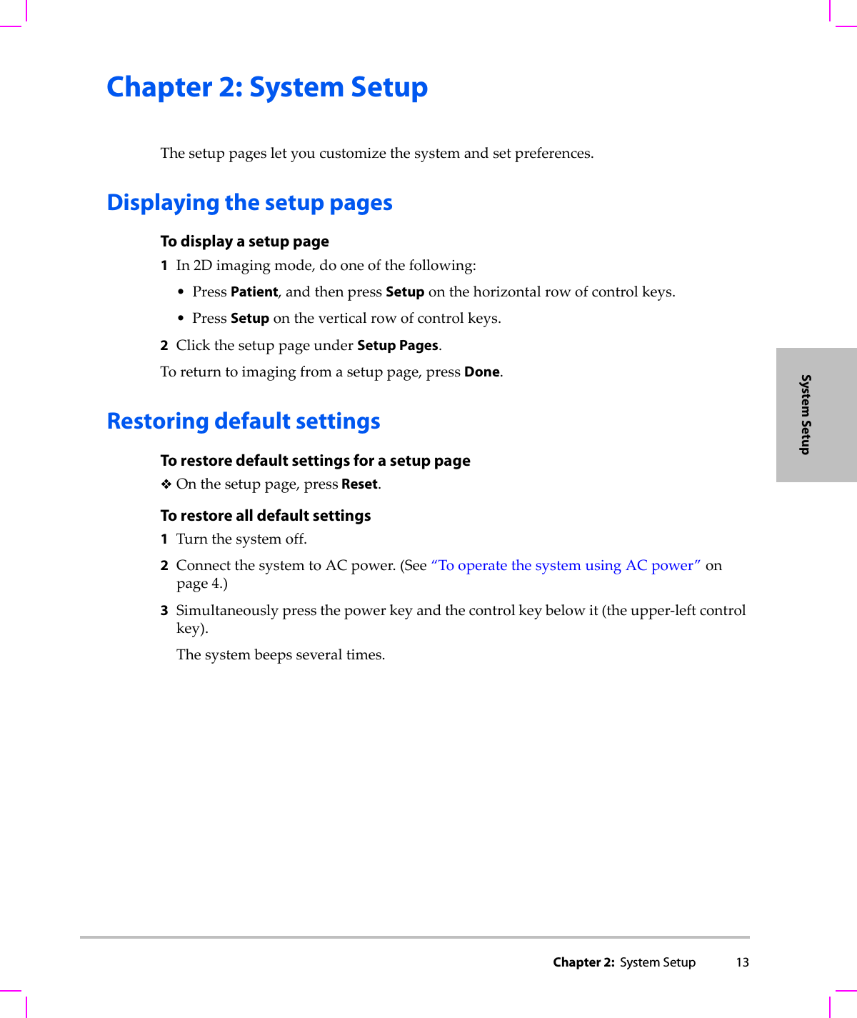
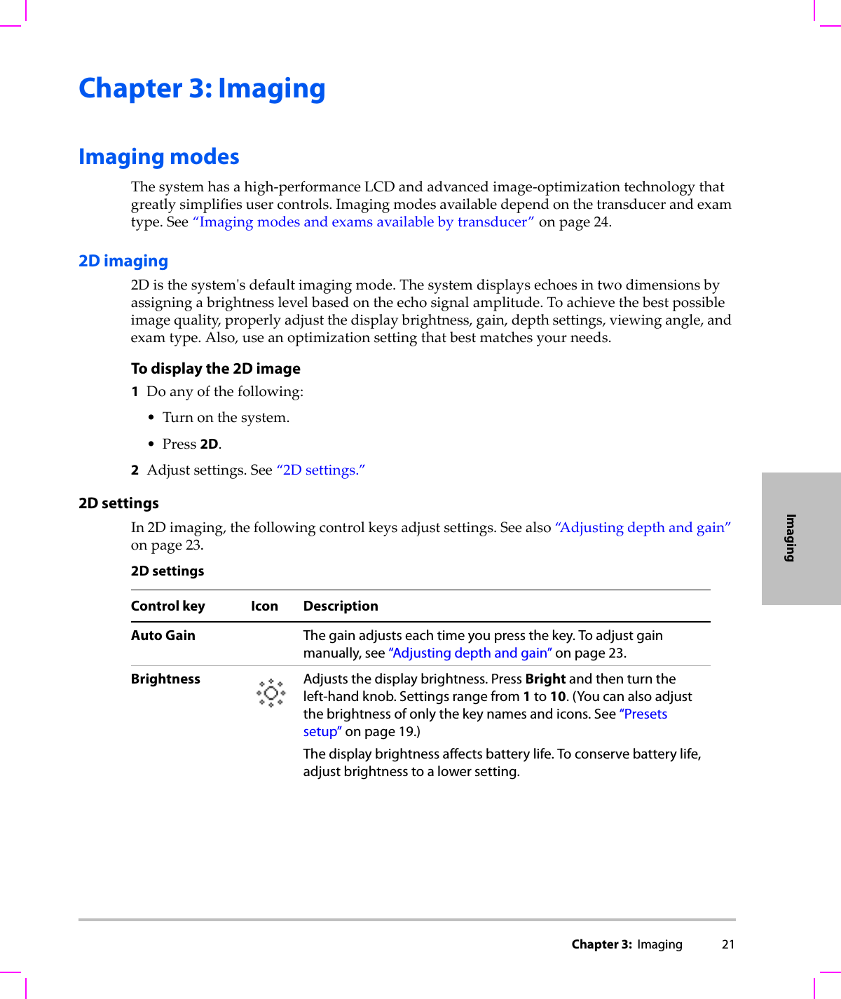
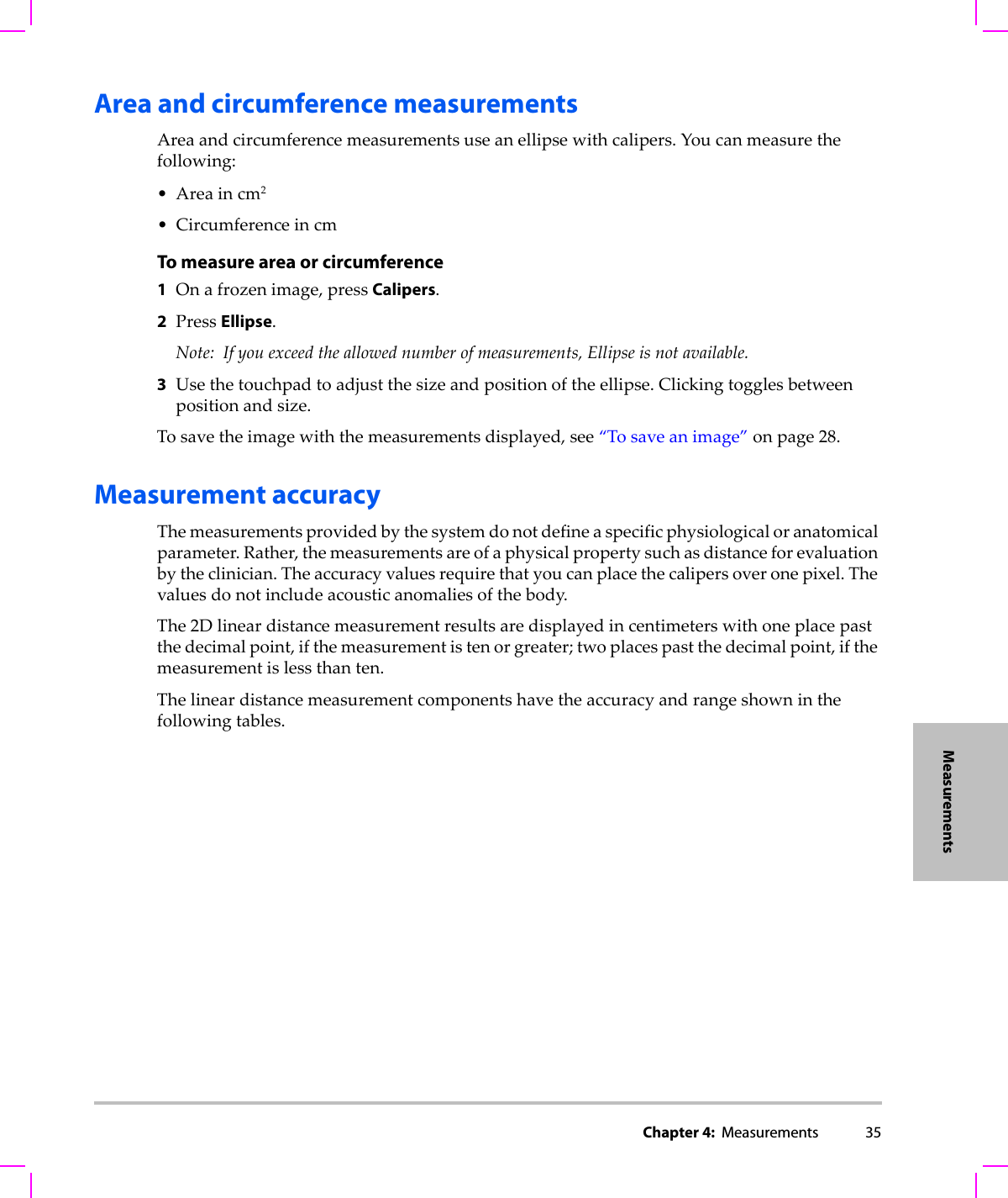
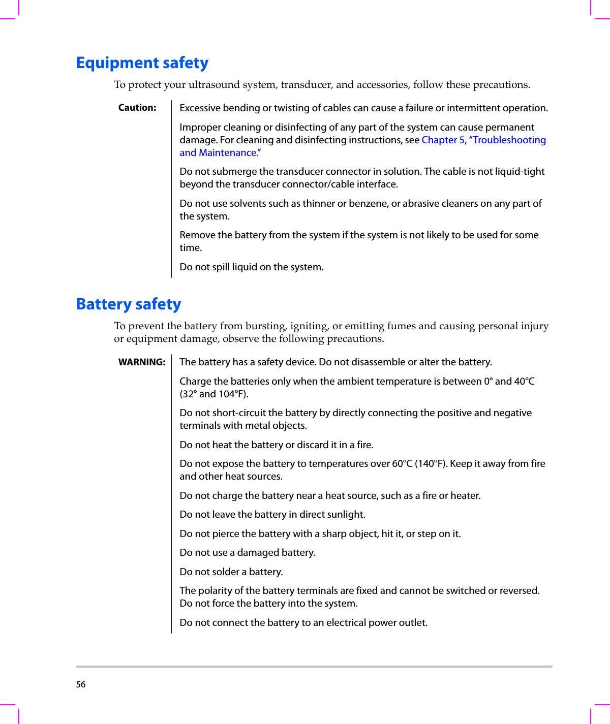
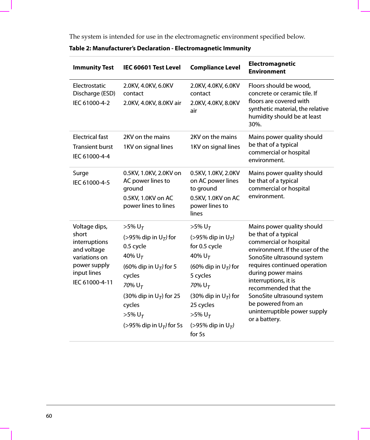
![Chapter 3: Imaging 23ImagingAdjusting depth and gainTo adjust depthYoucanadjustthedepthinallimagingmodes.Theverticaldepthscaleismarkedin0.5 cm,1cm,and5cmincrements,dependingonthedepth.Tochangethestyleofdepthmarkers,see“Presetssetup”onpage 19.TurntheDepthknob:•Rightincreasesthedisplayeddepth.•Leftdecreasesthedisplayeddepth.To adjust gain manuallyToadjustgainautomaticallyin2D,see“2Dsettings”onpage 21.1Presstheleft‐handknobtoselectasetting:•Nearadjuststhegainappliedtothenearfieldoftheimage.•Faradjuststhegainappliedtothefarfieldoftheimage.•Gain adjuststheoverallgainappliedtotheentireimage.InCPDorColorimaging,theOverallsettingaffectsthecolorgainappliedtotheregionofinterest(ROI)box.TheNearandFarsettingsaffectonlythe2Dimage.(Nearandfarcorrespondtothetimegaincompensation[TGC]controlsonotherultrasoundsystems.)2Turntheknob.Freezing, viewing frames, and zoomingTo freeze or unfreeze an imagePressFreeze.Onafrozenimage,thecineiconandframenumberappearinthesystemstatusarea.To move forward or backward in the cine bufferOnafrozenimage,turnthecineknob.Thetotalnumberofframesappearsnexttothecineicon.Thenumberchangestothecurrentframenumberasyoumoveforwardorbackward.](https://usermanual.wiki/J-Three-Holding/BU2073J.User-Manual-S-Series/User-Guide-1089451-Page-33.png)

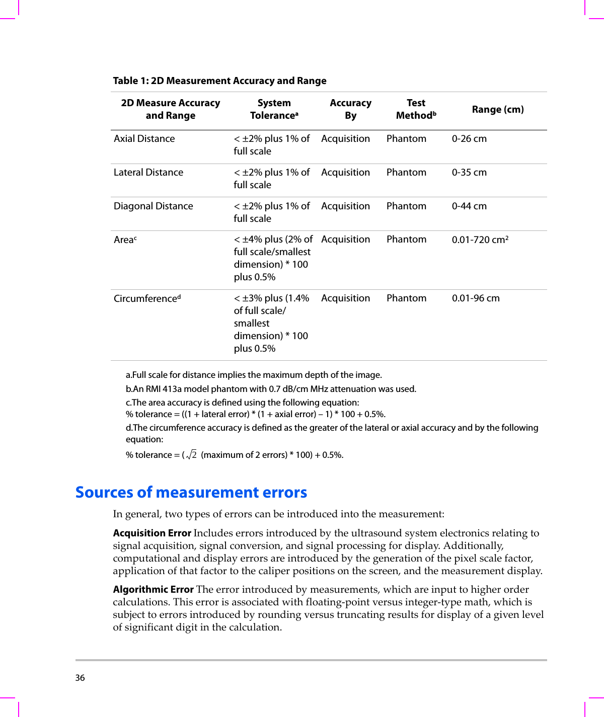

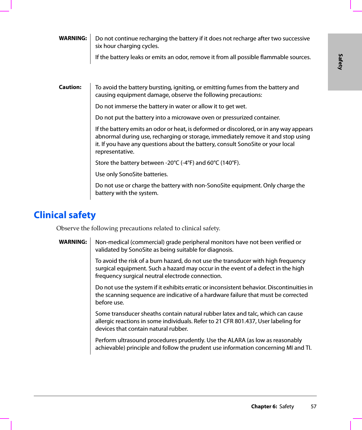
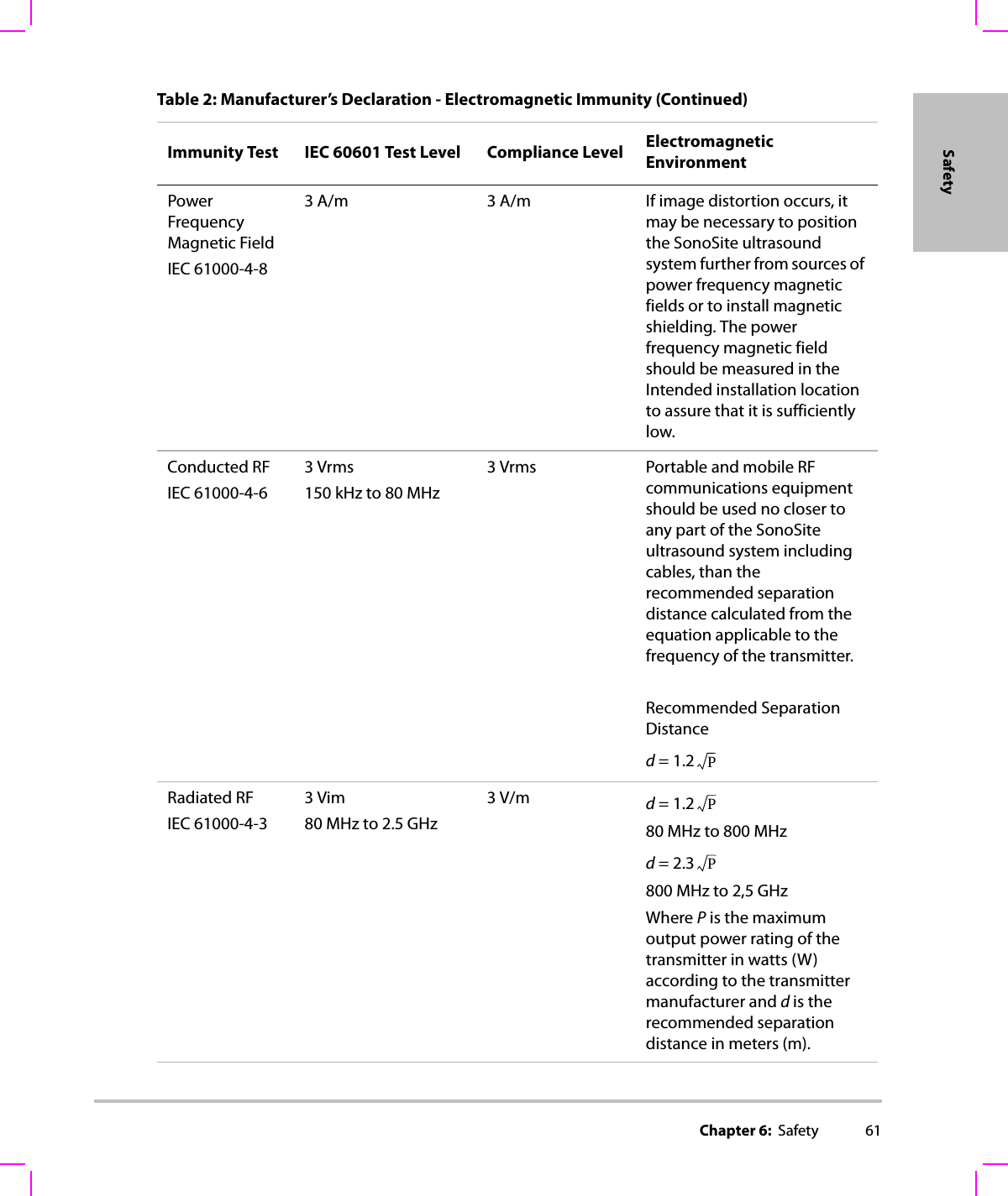
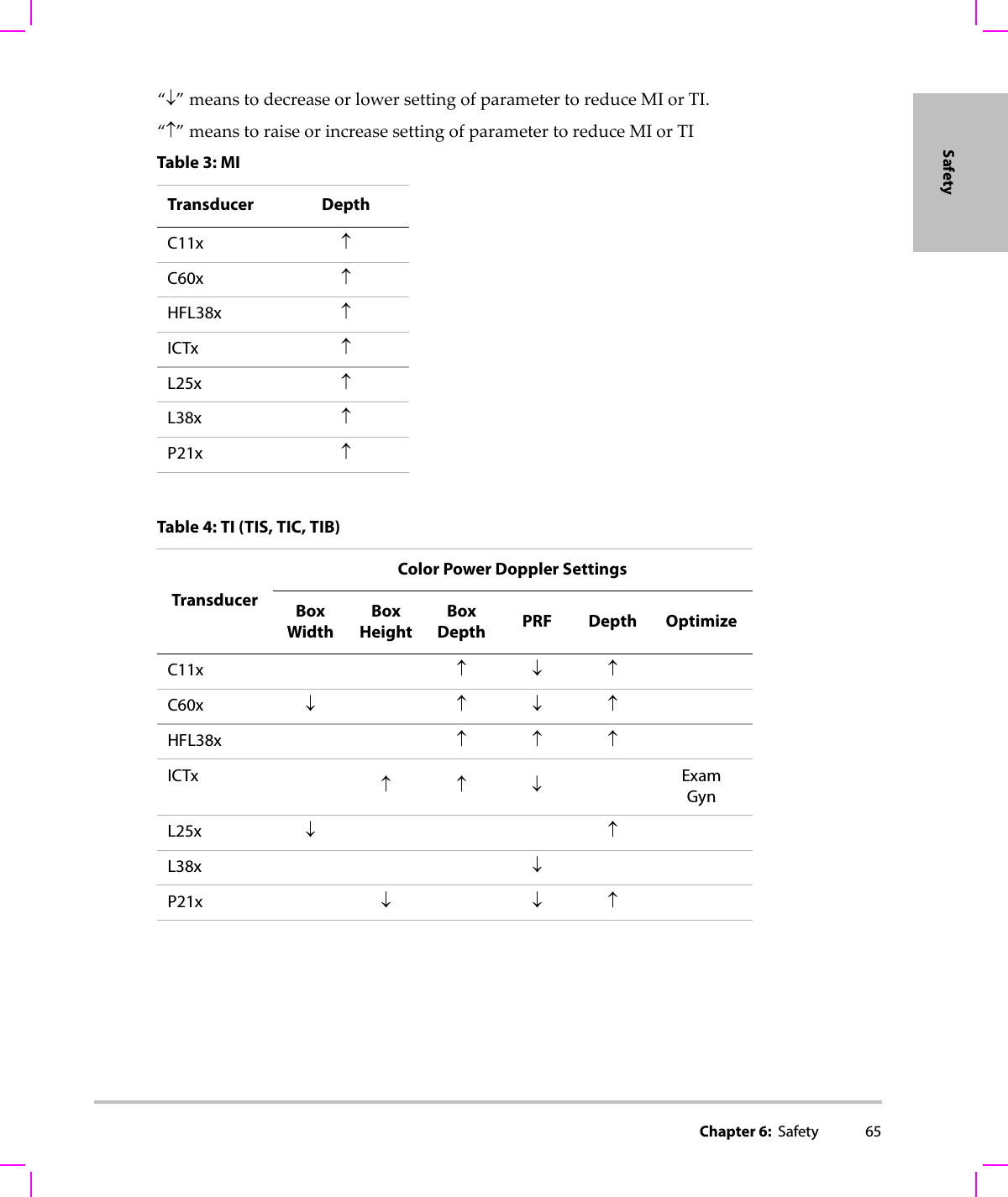
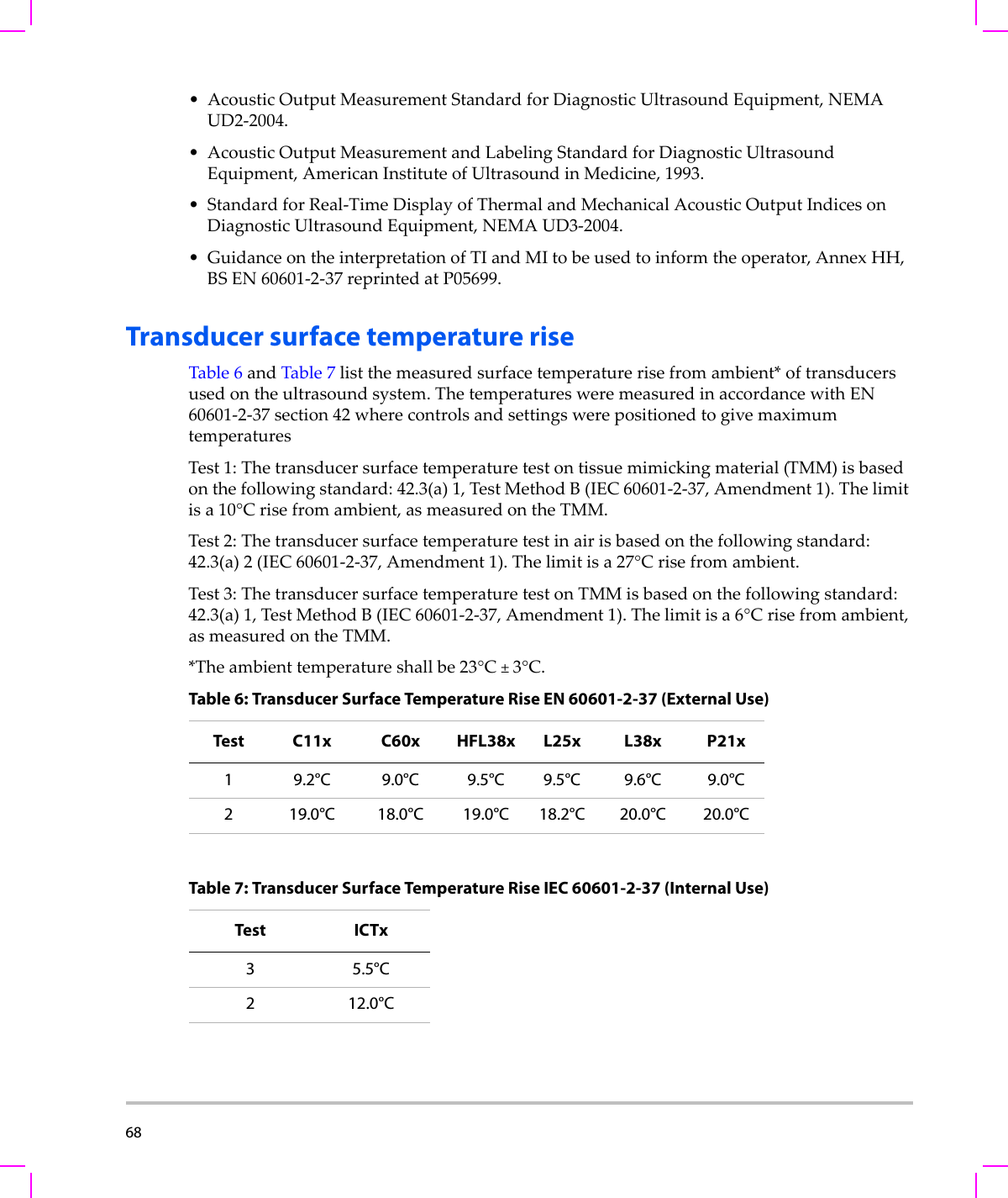
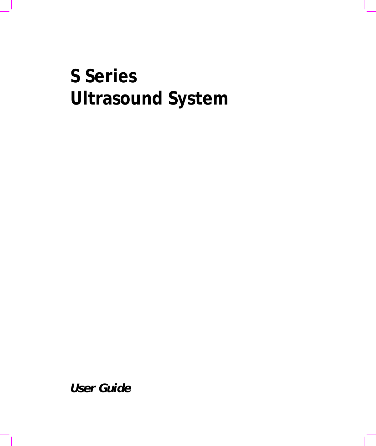
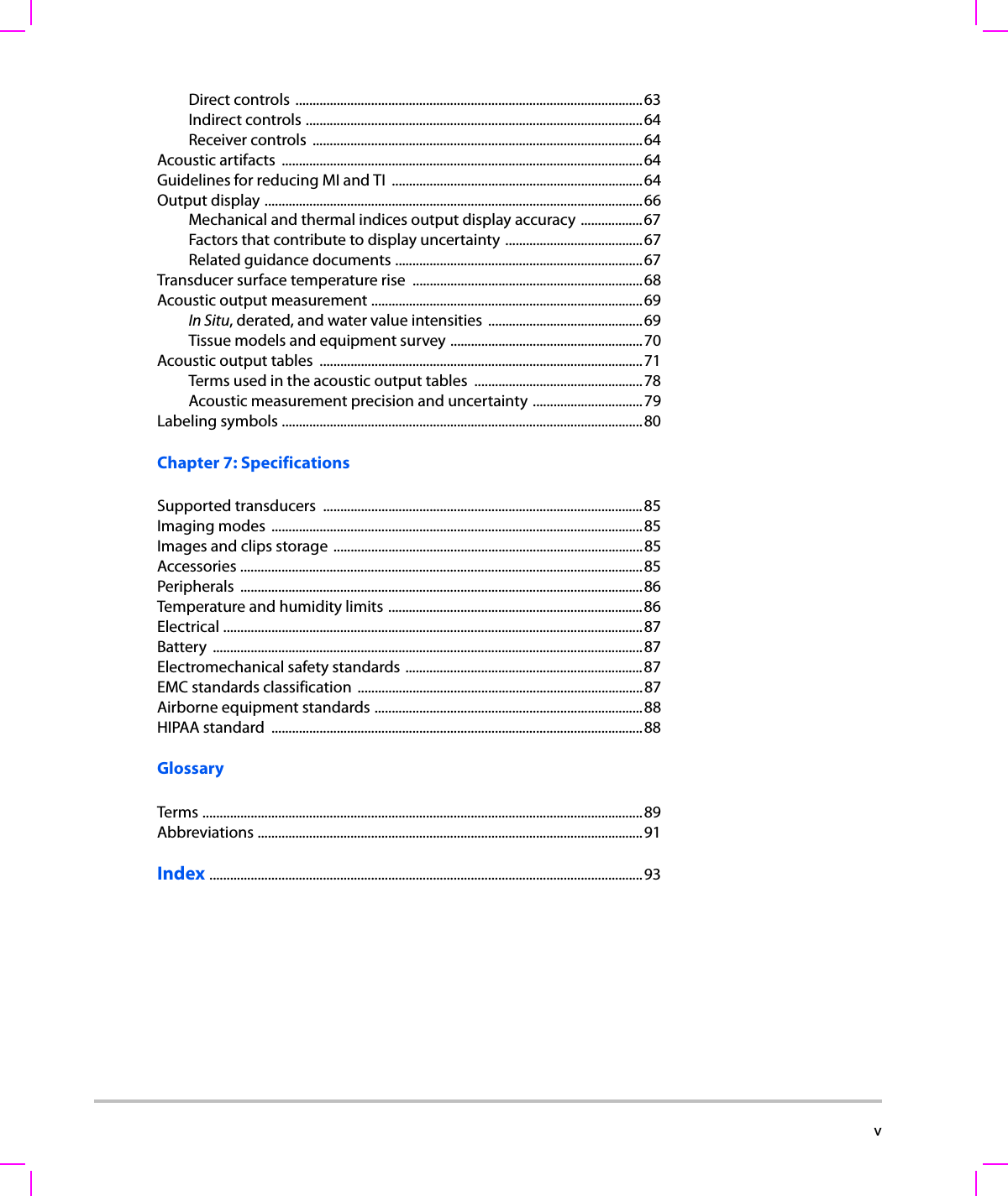
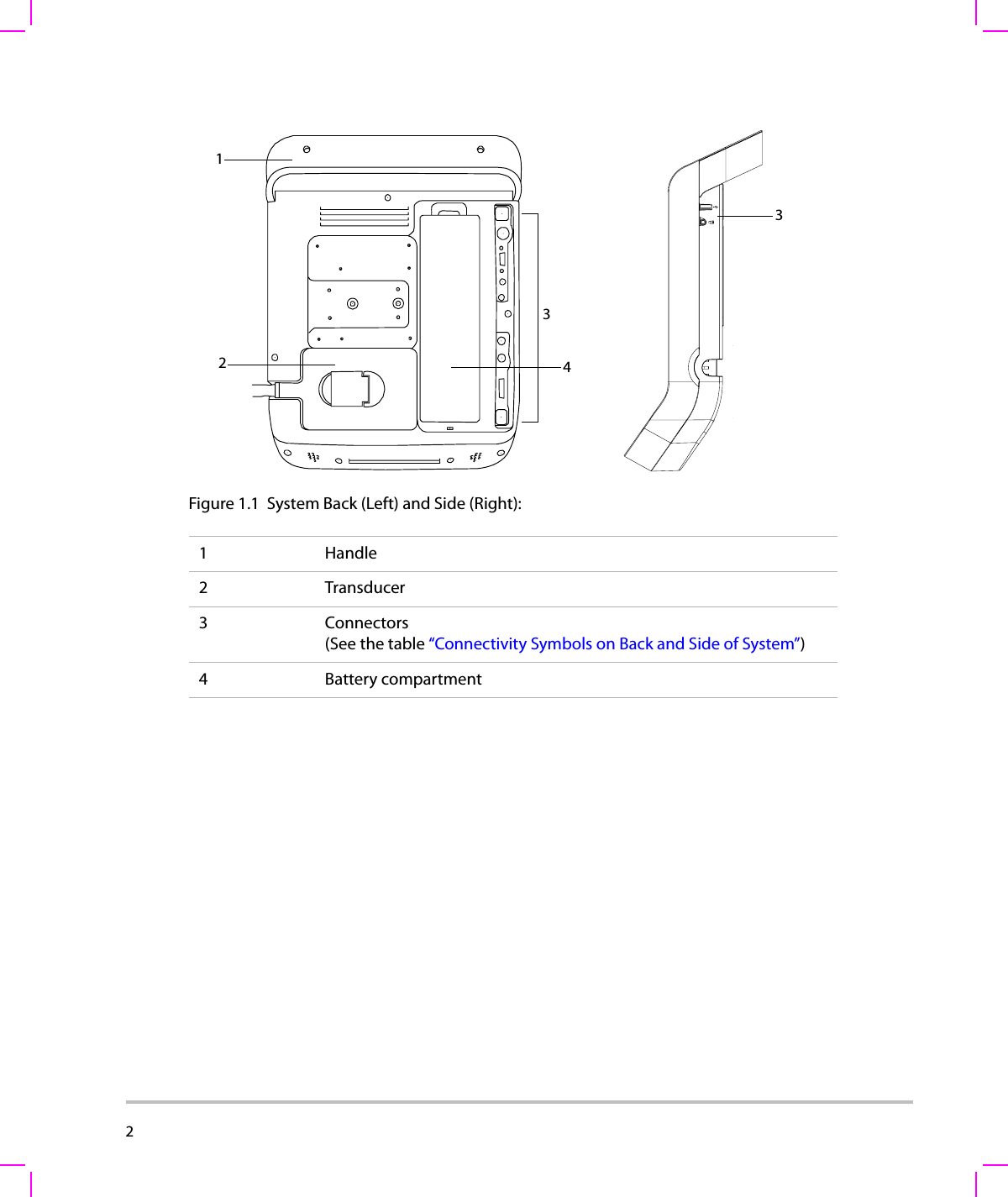
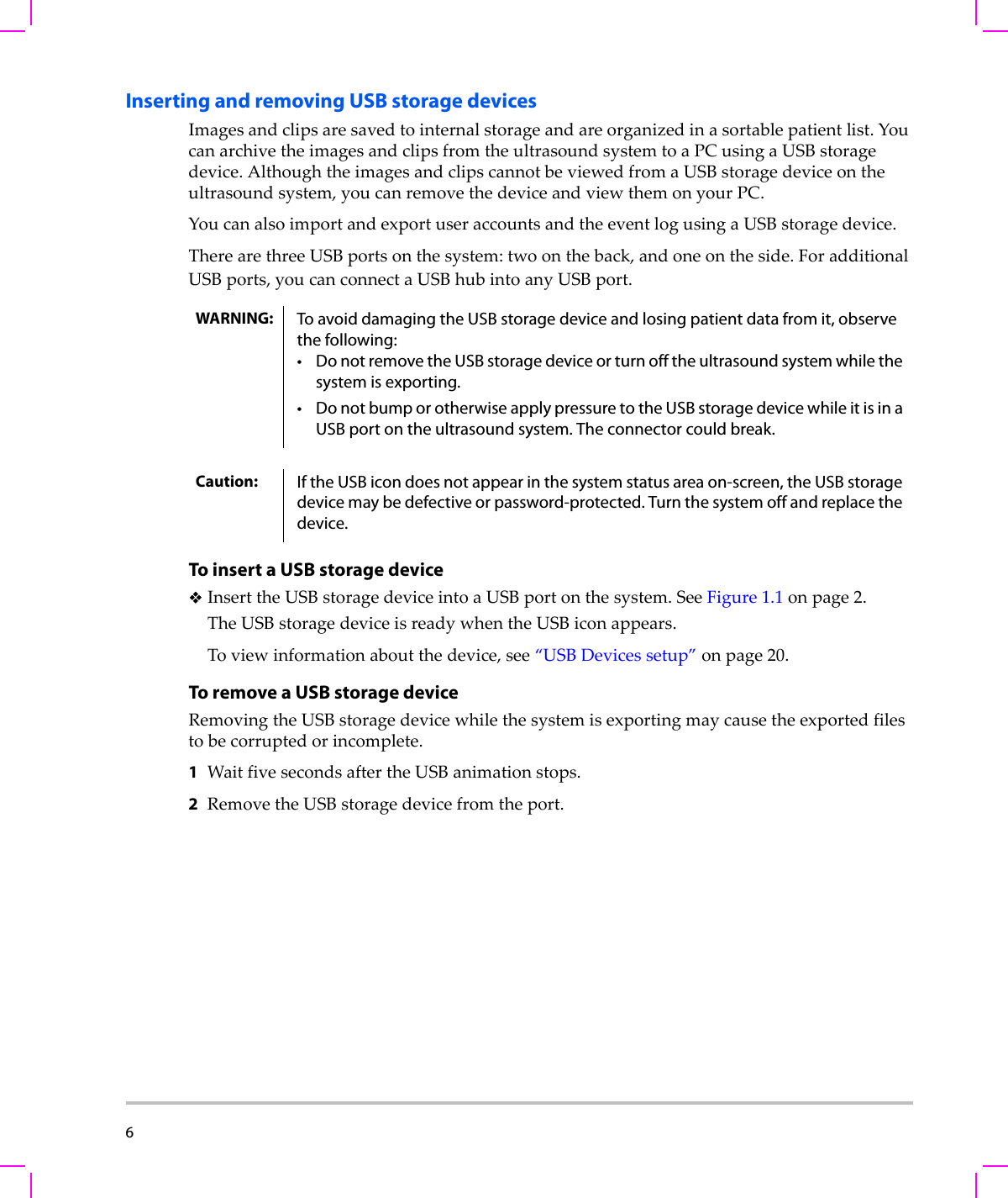
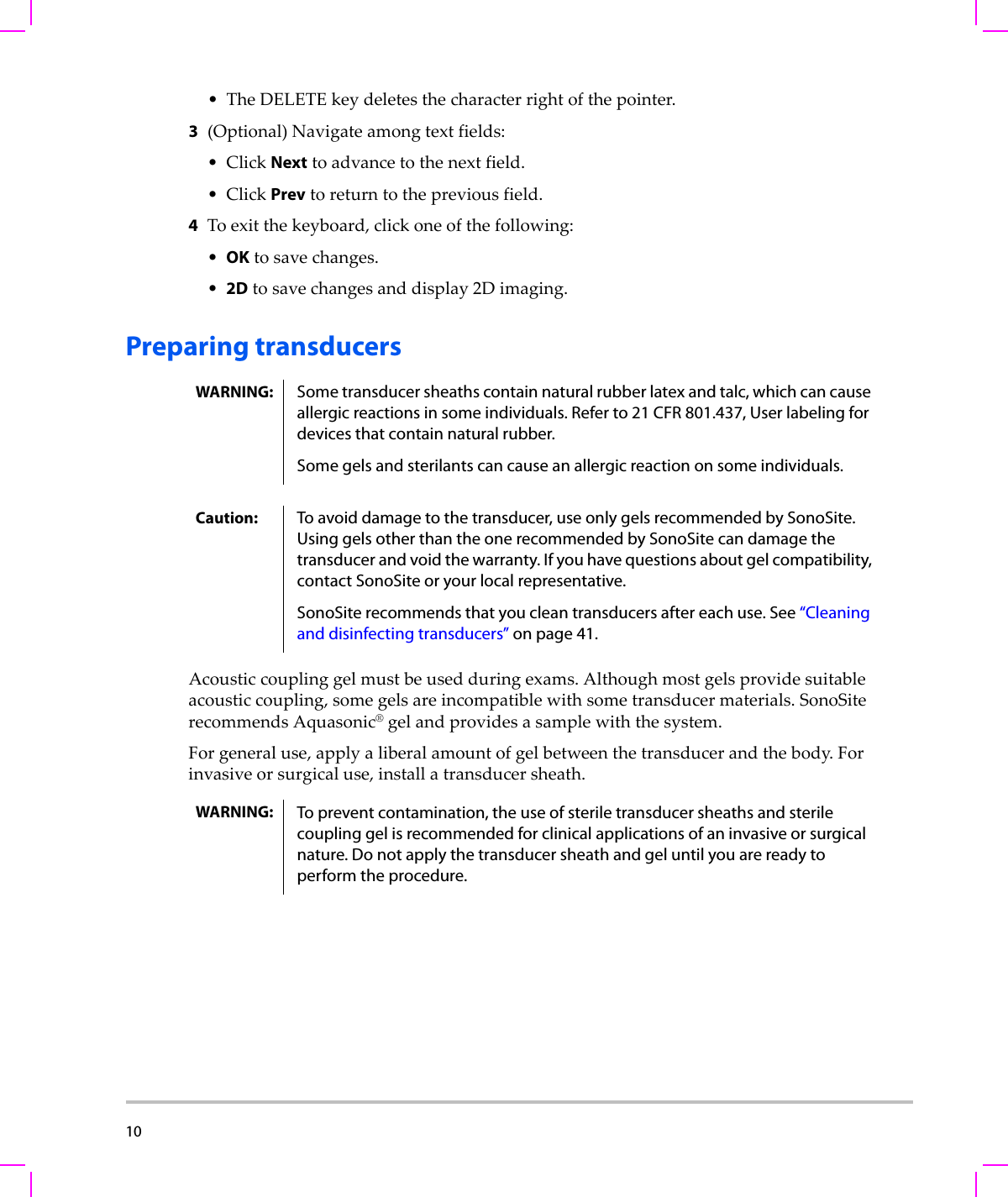
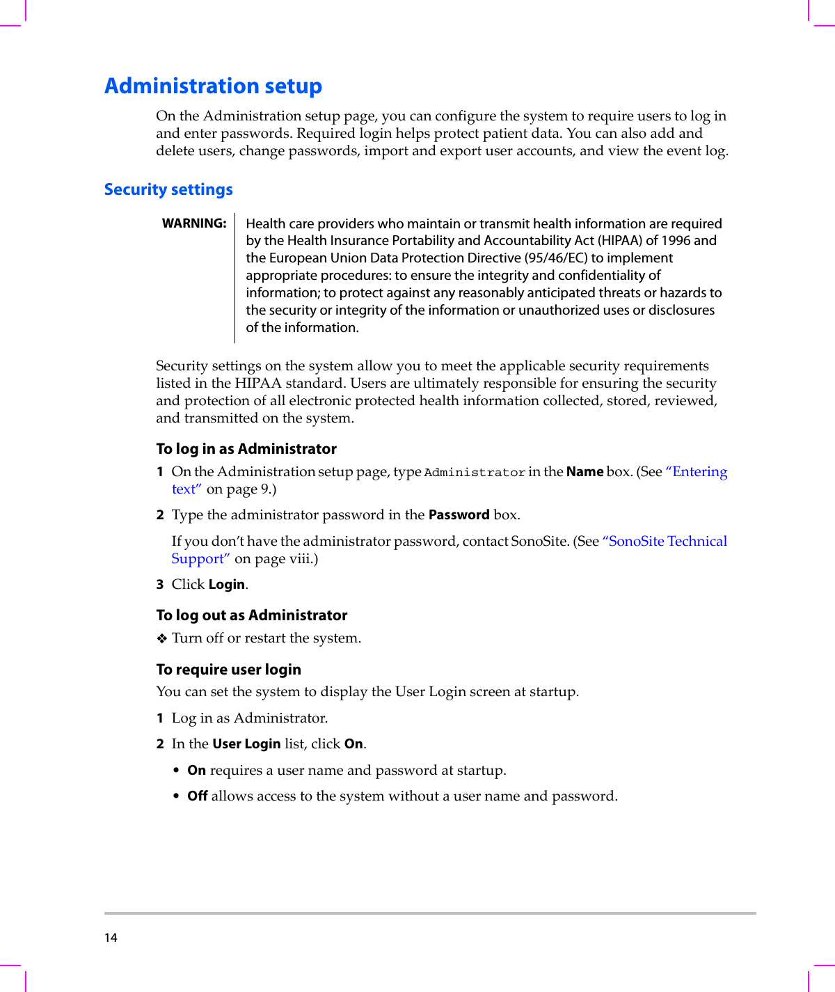
![Chapter 6: Safety 69SafetyAcoustic output measurementSincetheinitialuseofdiagnosticultrasound,thepossiblehumanbiologicaleffects(bioeffects)fromultrasoundexposurehavebeenstudiedbyvariousscientificandmedicalinstitutions.InOctober1987,theAmericanInstituteofUltrasoundinMedicine(AIUM)ratifiedareportpreparedbyitsBioeffectsCommittee(BioeffectsConsiderationsfortheSafetyofDiagnosticUltrasound,JUltrasoundMed.,Sept.1988:Vol.7,No.9Supplement),sometimesreferredtoastheStoweReport,whichreviewedavailabledataonpossibleeffectsofultrasoundexposure.Anotherreport“BioeffectsandSafetyofDiagnosticUltrasound,”datedJanuary28,1993providesmorecurrentinformation.Theacousticoutputforthisultrasoundsystemhasbeenmeasuredandcalculatedinaccordancewiththe“A c o u s t i c OutputMeasurementStandardforDiagnosticUltrasoundEquipment”(NEMAUD2‐2004),andthe“StandardforReal‐TimeDisplayofThermalandMechanicalAcousticOutputIndicesonDiagnosticUltrasoundEquipment”(NEMAUDe3‐2004).In Situ, derated, and water value intensitiesAllintensityparametersaremeasuredinwater.Sincewaterdoesnotabsorbacousticenergy,thesewatermeasurementsrepresentaworstcasevalue.Biologicaltissuedoesabsorbacousticenergy.Thetruevalueoftheintensityatanypointdependsontheamount,typeoftissue,andthefrequencyoftheultrasoundpassingthroughthetissue.Theintensityvalueinthetissue,In Situ,hasbeenestimatedbyusingthefollowingformula:In Situ=Water[e‐(0.23alf)]where:In Situ=In SituintensityvalueWater=Waterintensityvaluee=2.7183a=attenuationfactor(dB/cm MHz)Attenuationfactor(a)forvarioustissuetypesaregivenbelow:brain=0.53heart=0.66kidney=0.79liver=0.43muscle=0.55l=skinlinetomeasurementdepthincmf=centerfrequencyofthetransducer/system/modecombinationinMHz](https://usermanual.wiki/J-Three-Holding/BU2073J.User-Manual-S-Series/User-Guide-1089451-Page-79.png)
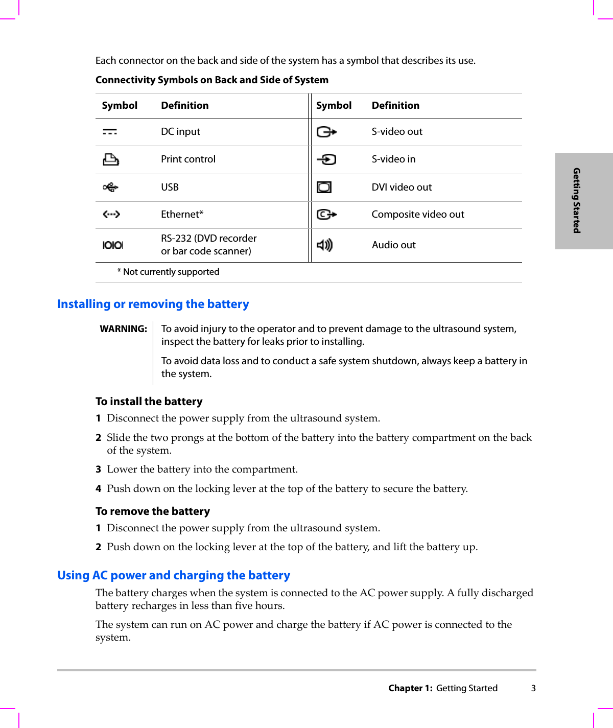
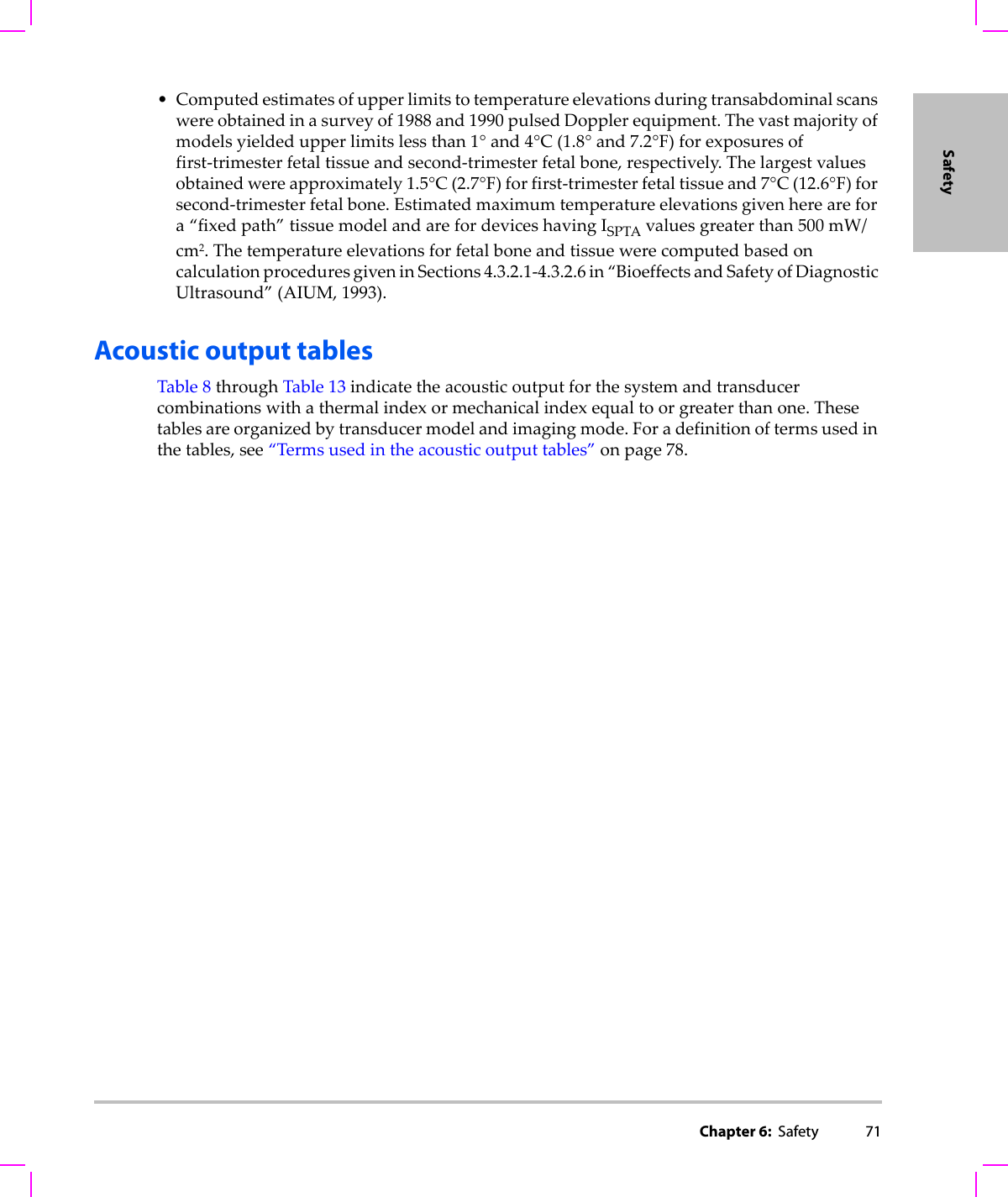
![70 Sincetheultrasonicpathduringtheexamislikelytopassthroughvaryinglengthsandtypesoftissue,itisdifficulttoestimatethetrueIn Situintensity.Anattenuationfactorof0.3isusedforgeneralreportingpurposes;therefore,theIn Situvaluecommonlyreportedusestheformula:In Situ(derated)=Water[e‐(0.069lf)]SincethisvalueisnotthetrueIn Situintensity,theterm“derated”isusedtoqualify it.Themaximumderatedandthemaximumwatervaluesdonotalwaysoccuratthesameoperatingconditions;therefore,thereportedmaximumwaterandderatedvaluesmaynotberelatedbytheIn Situ(derated)formula.Forexample:amulti‐zonearraytransducerthathasmaximumwatervalueintensitiesinitsdeepestzone,butalsohasthesmallestderatingfactorinthatzone.Thesametransducermayhaveitslargestderatedintensityinoneofitsshallowestfocalzones.Tissue models and equipment surveyTissuemodelsarenecessarytoestimateattenuationandacousticexposurelevelsIn Situfrommeasurementsofacousticoutputmadeinwater.Currently,availablemodelsmaybelimitedintheiraccuracybecauseofvaryingtissuepathsduringdiagnosticultrasoundexposuresanduncertaintiesintheacousticpropertiesofsofttissues.Nosingletissuemodelisadequateforpredictingexposuresinallsituationsfrommeasurementsmadeinwater,andcontinuedimprovementandverificationofthesemodelsisnecessaryformakingexposureassessmentsforspecificexamtypes.Ahomogeneoustissuemodelwithattenuationcoefficientof0.3 dB/cm MHzthroughoutthebeampathiscommonlyusedwhenestimatingexposurelevels.ThemodelisconservativeinthatitoverestimatestheIn Situacousticexposurewhenthepathbetweenthetransducerandsiteofinterestiscomposedentirelyofsofttissue.Whenthepathcontainssignificantamountsoffluid,asinmanyfirstandsecond‐trimesterpregnanciesscannedtransabdominally,thismodelmayunderestimatetheIn Situacousticexposure.Theamountofunderestimationdependsuponeachspecificsituation.Fixed‐pathtissuemodels,inwhichsofttissuethicknessisheldconstant,sometimesareusedtoestimateIn Situacousticexposureswhenthebeampathislongerthan3cmandconsistslargelyoffluid.Whenthismodelisusedtoestimatemaximumexposuretothefetusduringtransabdominalscans,avalueof1dB/cmMHzmaybeusedduringalltrimesters.Existingtissuemodelsthatarebasedonlinearpropagationmayunderestimateacousticexposureswhensignificantsaturationduetonon‐lineardistortionofbeamsinwaterispresentduringtheoutputmeasurement.Themaximumacousticoutputlevelsofdiagnosticultrasounddevicesextendoverabroadrangeofvalues:•Asurveyof1990‐equipmentmodelsyieldedMIvaluesbetween0.1 and1.0attheirhighestoutputsettings.MaximumMIvaluesofapproximately2.0areknowntooccurforcurrentlyavailableequipment.MaximumMIvaluesaresimilarforreal‐time2DandMModeimaging.](https://usermanual.wiki/J-Three-Holding/BU2073J.User-Manual-S-Series/User-Guide-1089451-Page-80.png)
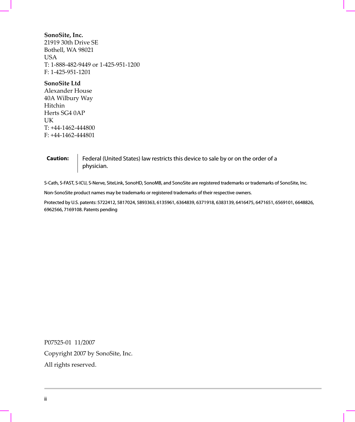
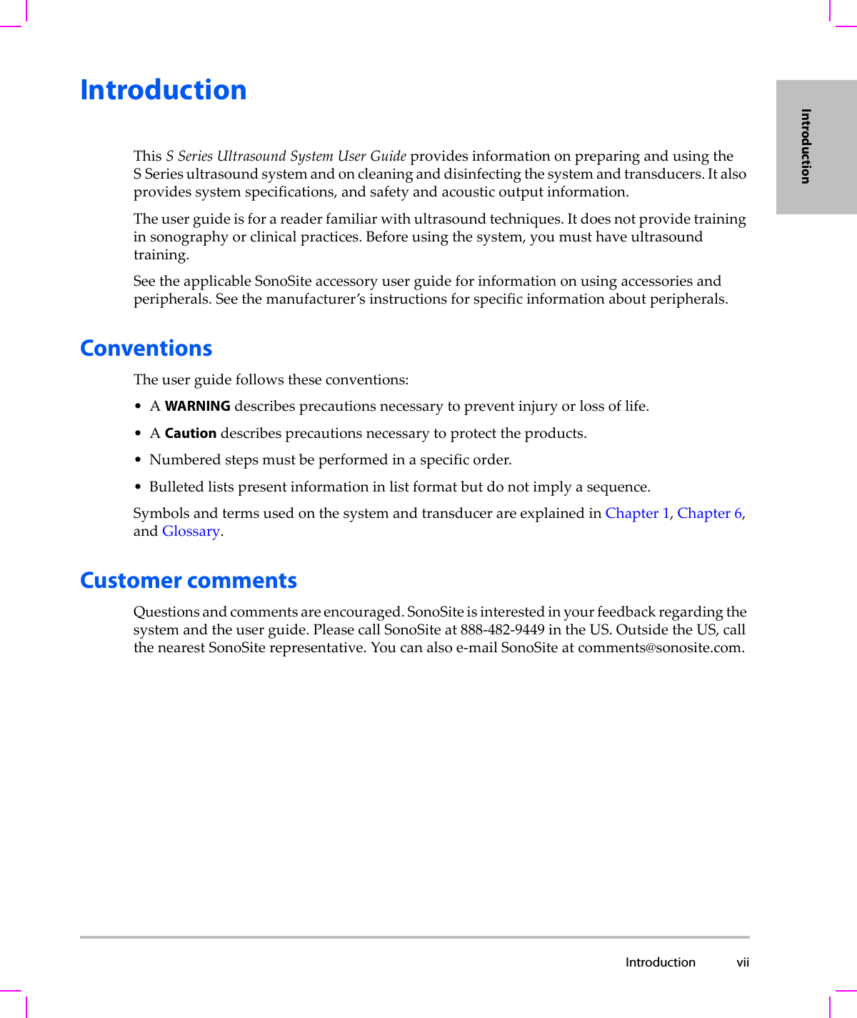
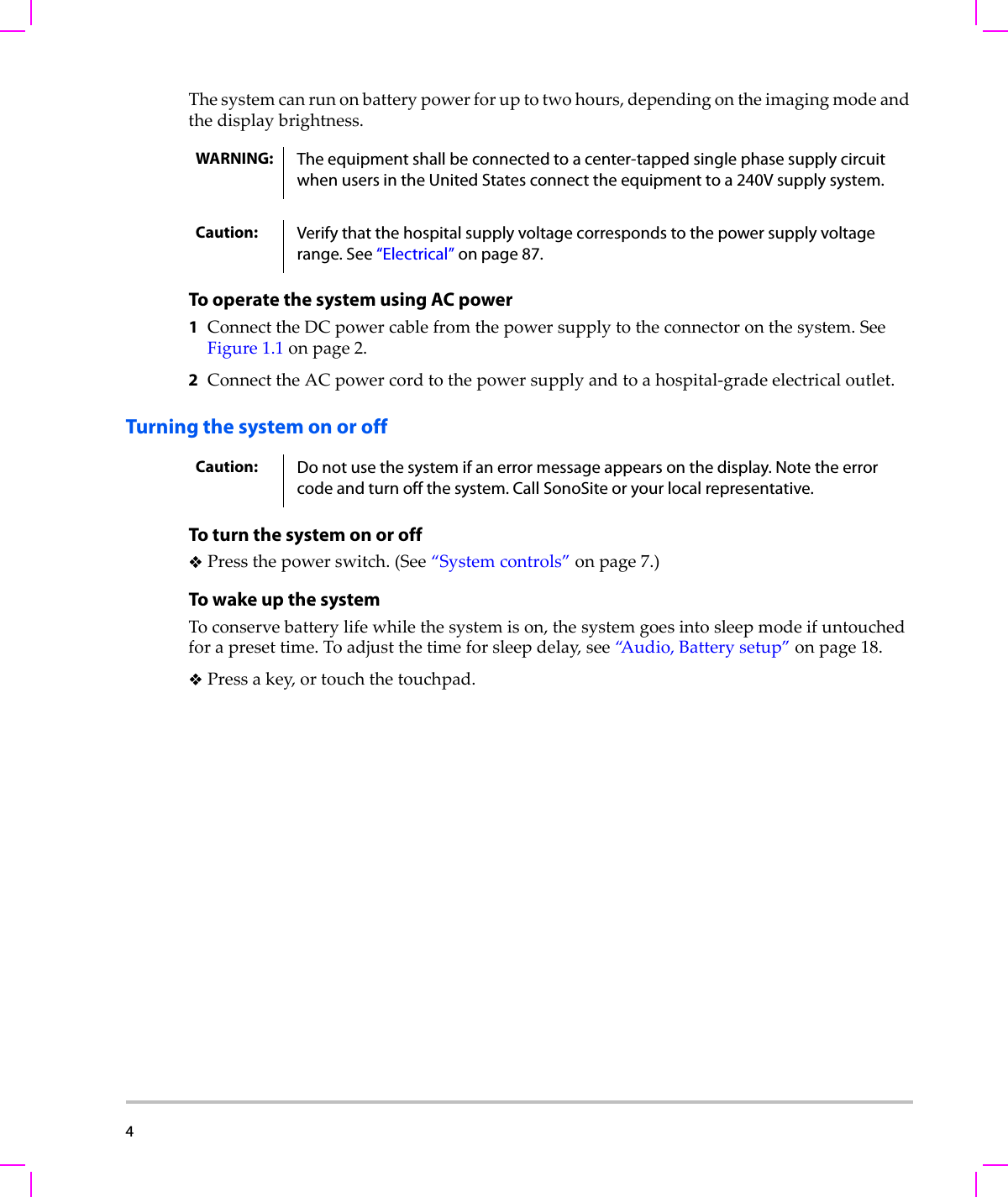
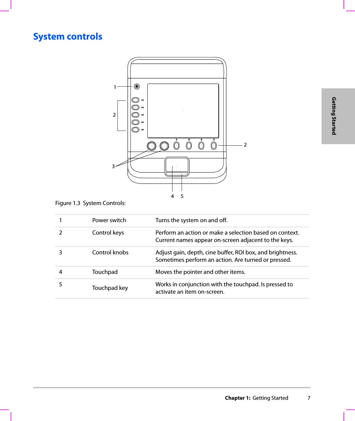
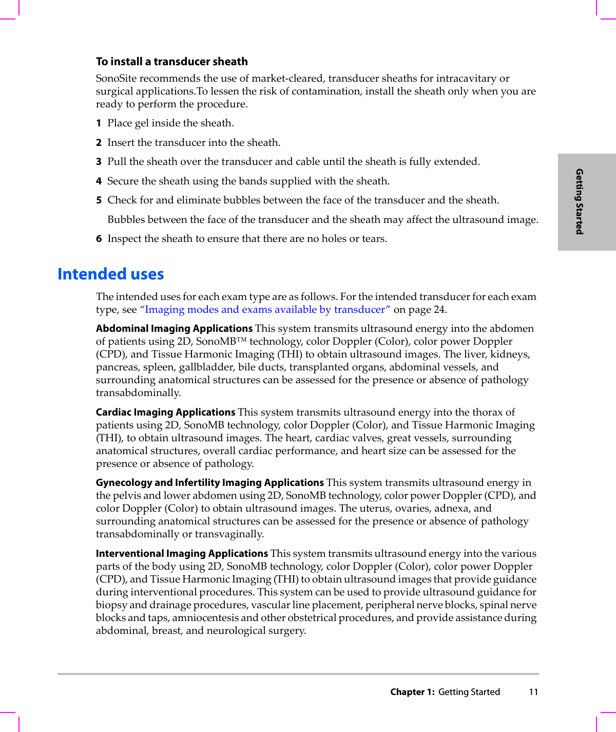
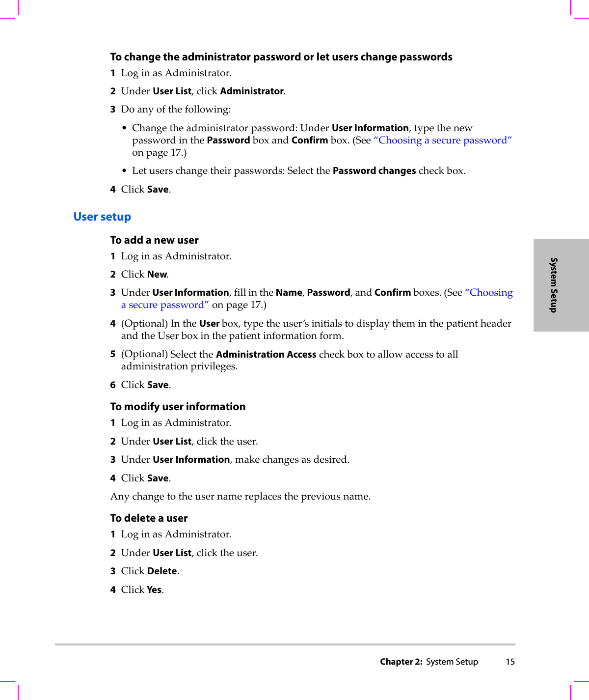
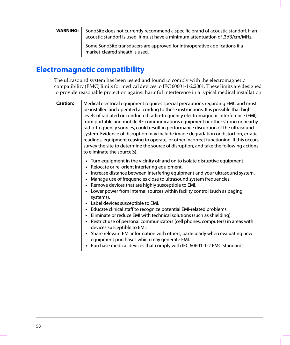
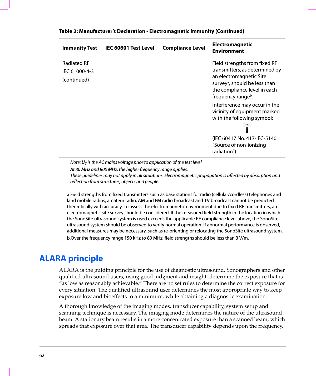
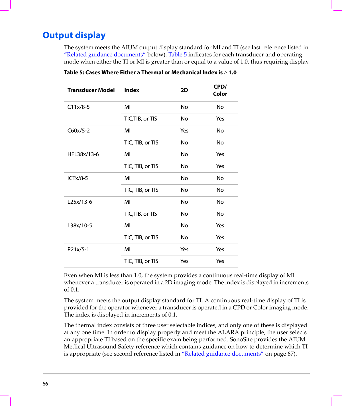
![72 (a) This index is not required for this operating mode; value is <1.(b) This transducer is not intended for transcranial or neonatal cephalic uses.#No data are reported for this operating condition since the global maximum index value is not reported for the reason listed. (Reference Global Maximum Index Value line.)— Data are not applicable for this transducer/mode.Table 8: Transducer Model: C11x/8-5 Operating Mode: CPD/ColorIndex Label M.I.TIS TIBTICScanNon-scanNon-scanAaprt≤1Aaprt>1Global Maximum Index Value (a) (a) — — — 1.2Associated AcousticParameterpr.3 (MPa) #W0(mW) #— —40.50min of [W.3(z1),ITA.3(z1)] (mW) —z1(cm) —zbp (cm) —zsp (cm) #—deq(zsp)(cm) —fc(MHz) ## — — — 4.38Dim of Aaprt X(cm) # — — — 0.36Y(cm) #—— —0.5Other InformationPD (μsec) #PRF (Hz) #pr@PIImax (MPa) #deq@Pllmax (cm) —Focal Length FLx (cm) #—— 1.56FLy (cm) #—— 2.5IPA.3@MImax (W/cm2)#OperatingControl ConditionsControl 1: Mode CPDControl 2: Exam Type VasControl 3: PRF 2841Control 4: Optimization/Depth Med/2.0Control 5: Color Box Position/ SizeTop/Short](https://usermanual.wiki/J-Three-Holding/BU2073J.User-Manual-S-Series/User-Guide-1089451-Page-82.png)
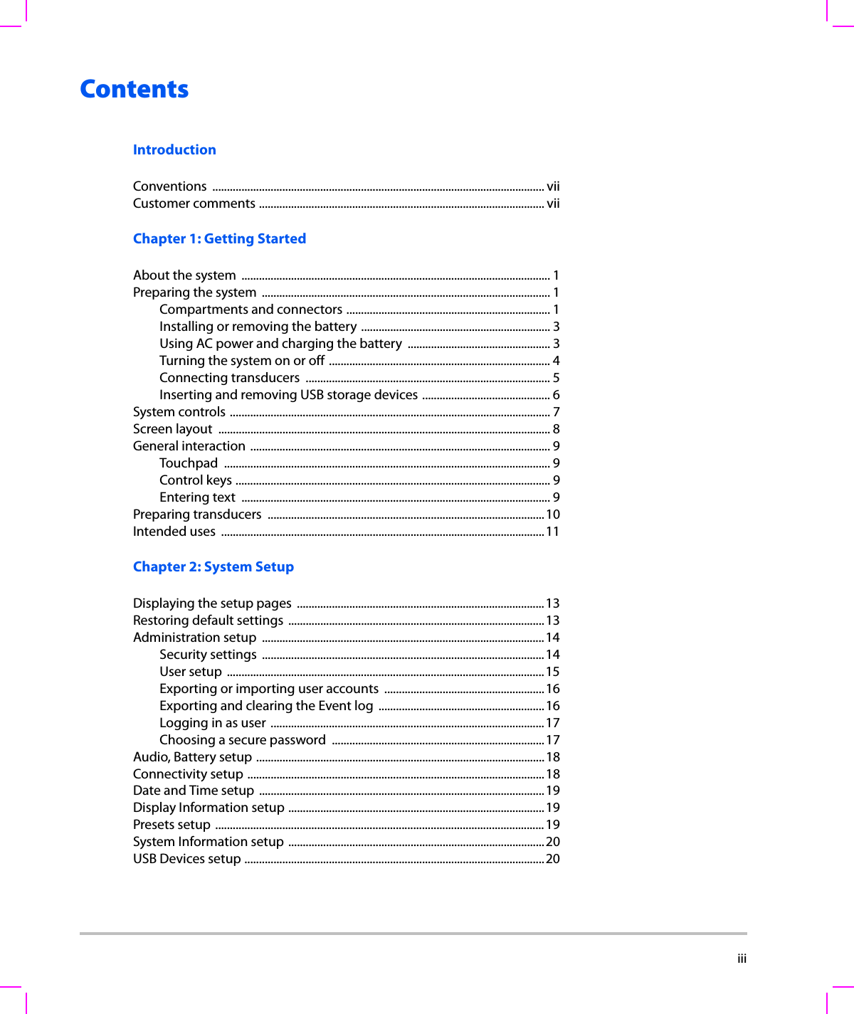
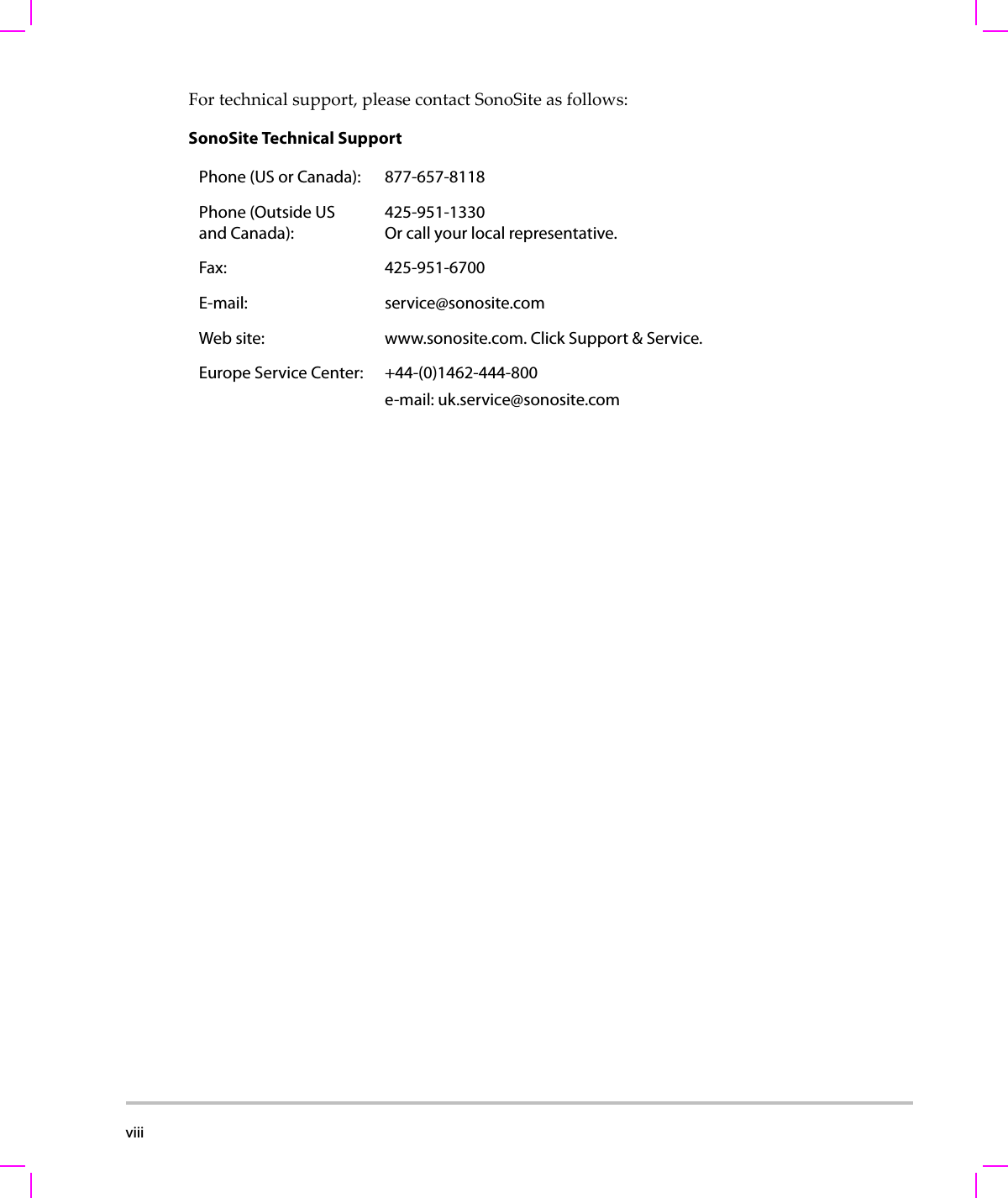
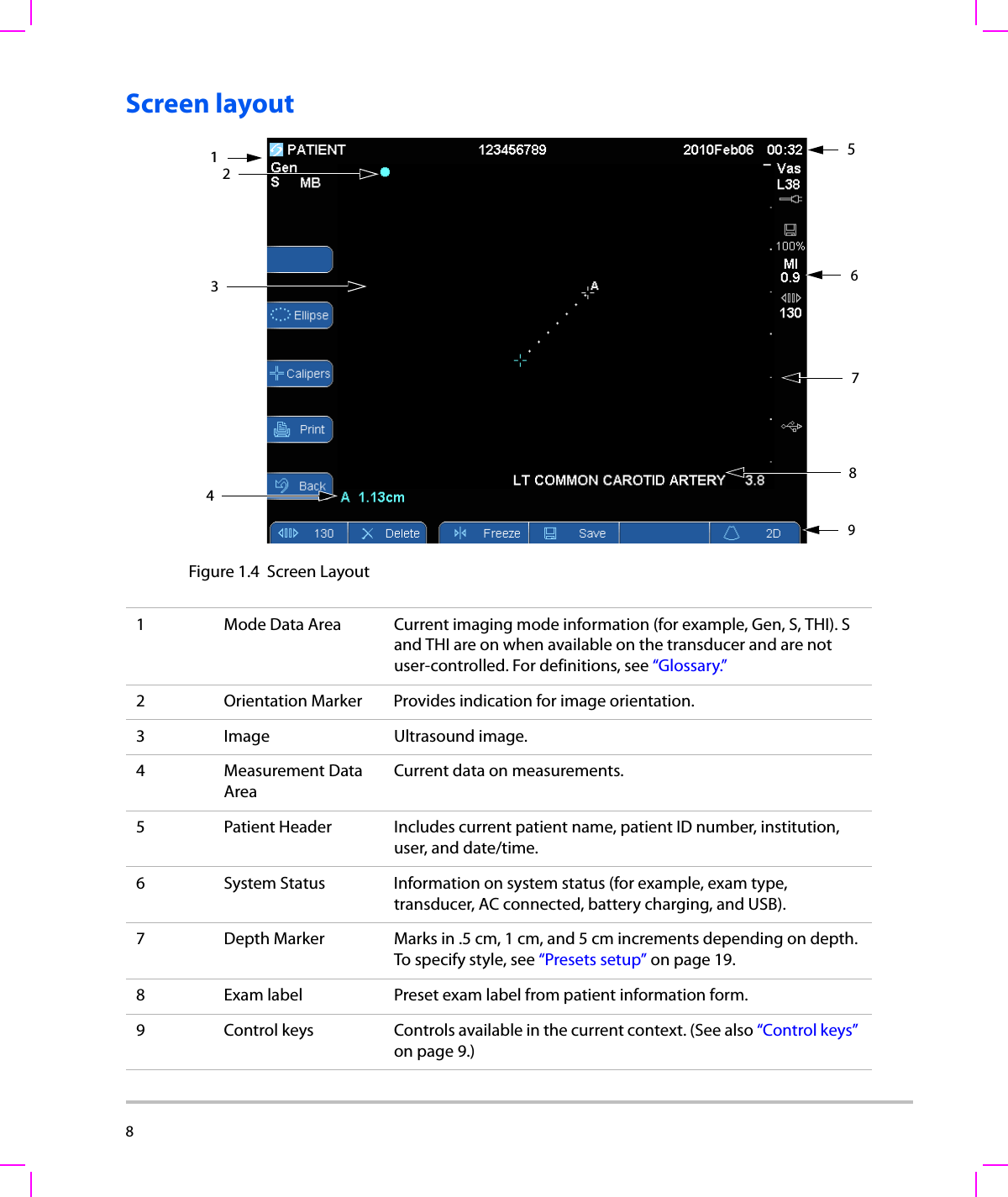
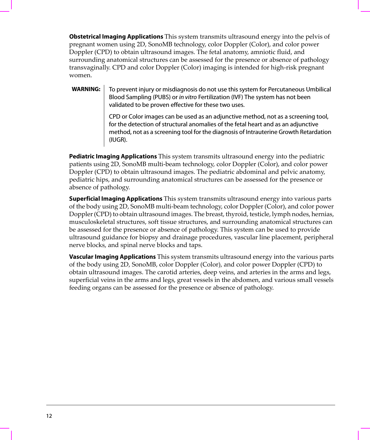
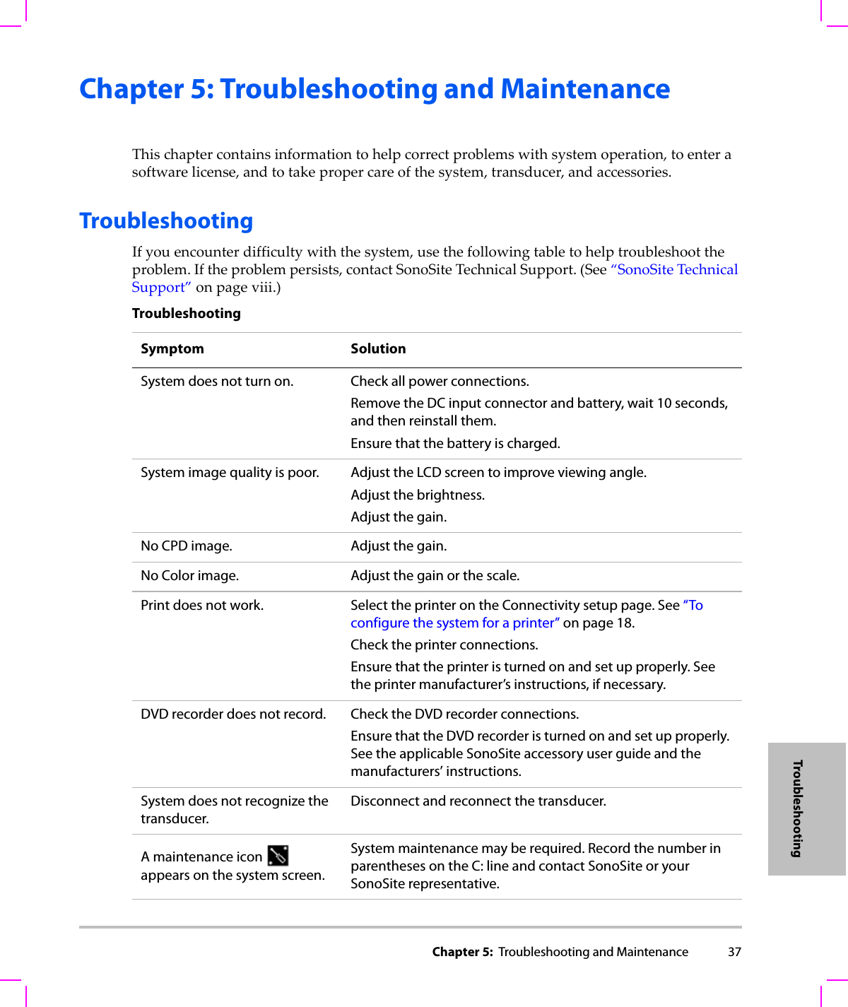
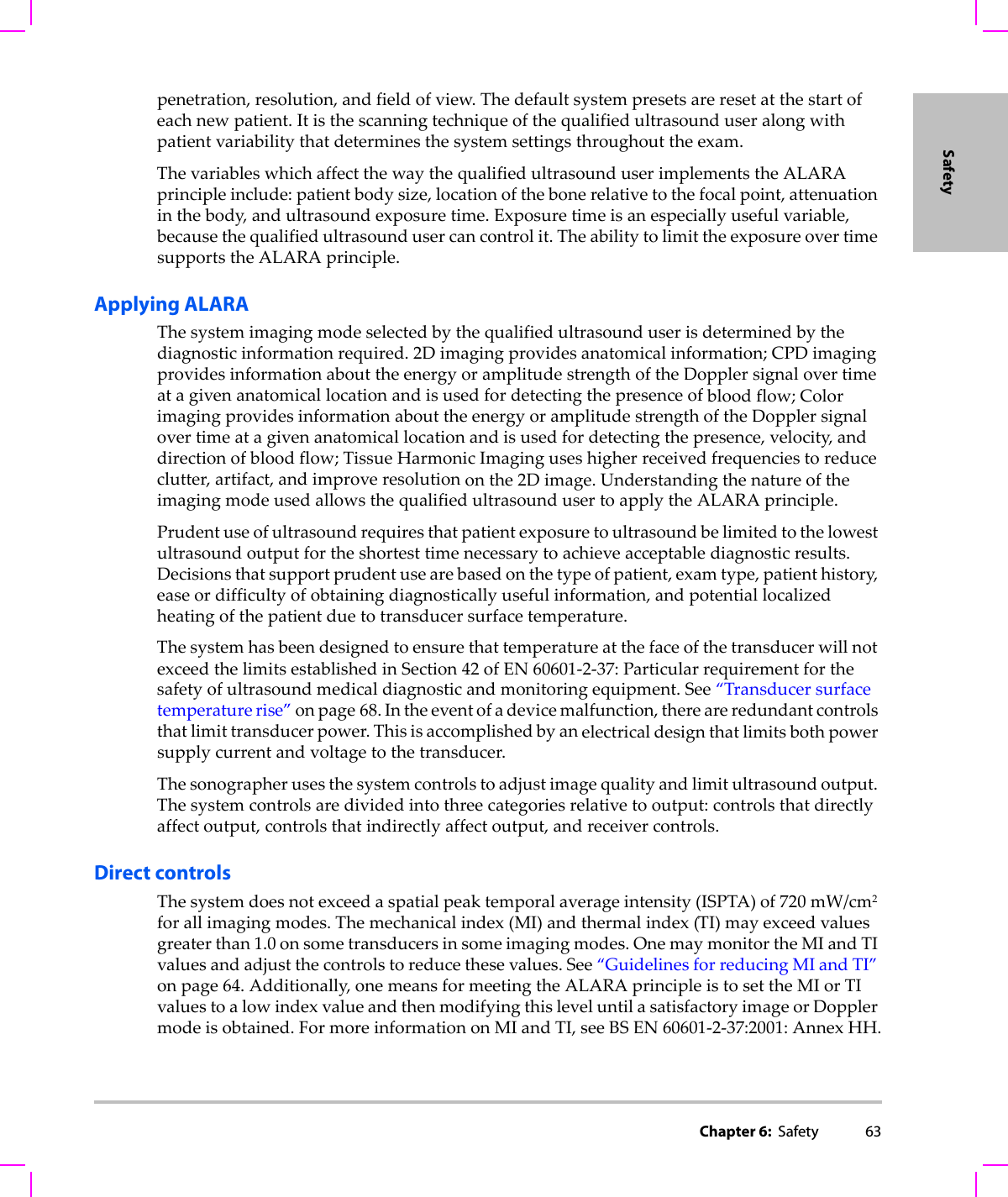
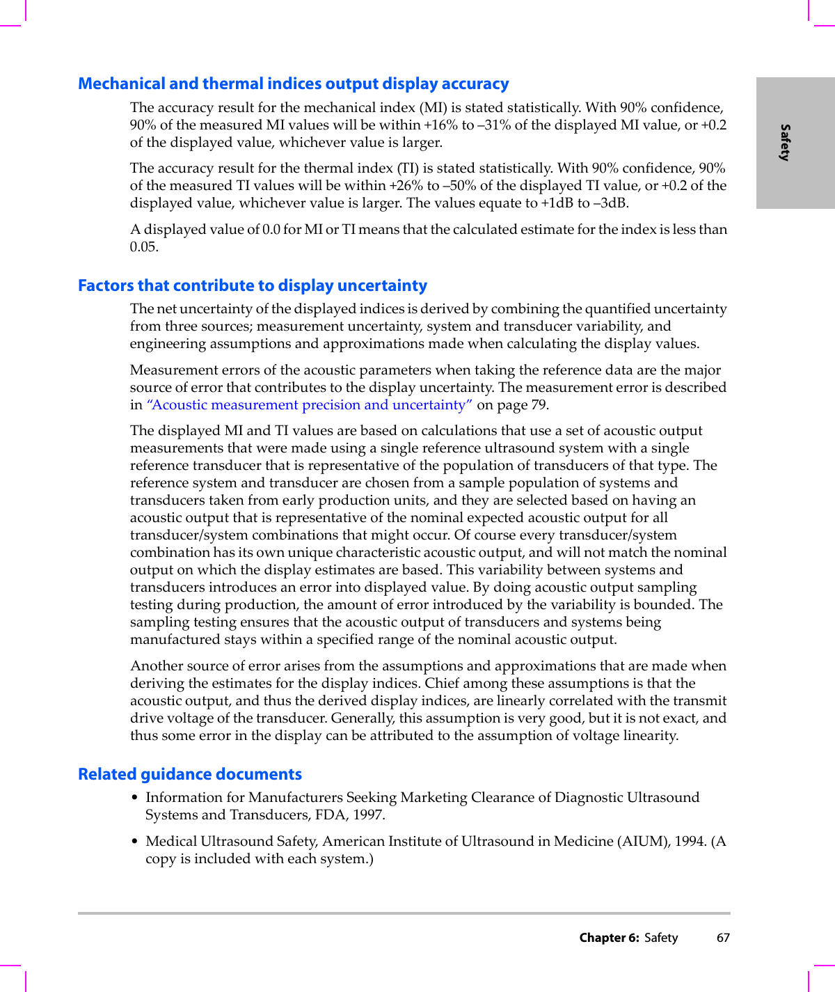
![Chapter 6: Safety 73Safety(a) This index is not required for this operating mode; value is <1.(b) This transducer is not intended for transcranial or neonatal cephalic uses.#No data are reported for this operating condition since the global maximum index value is not reported for the reason listed. (Reference Global Maximum Index Value line.)— Data are not applicable for this transducer/mode.Table 9: Transducer Model: C60x/5-2 Operating Mode: 2DIndex Label M.I.TIS TIBTICScanNon-scanNon-scanAaprt≤1Aaprt>1Global Maximum Index Value 1.0 (a) — — — (b)Associated AcousticParameterpr.3 (MPa) 1.59W0(mW) #— —#min of [W.3(z1),ITA.3(z1)] (mW) —z1(cm) —zbp (cm) —zsp (cm) 5.3 —deq(zsp)(cm) —fc(MHz) 2.86 # — — — #Dim of Aaprt X(cm) #—— — #Y(cm) #—— — #Other InformationPD (μsec) 0.579PRF (Hz) 7923pr@PIImax (MPa) 2.679deq@Pllmax (cm) —Focal Length FLx (cm) #—— #FLy (cm) #—— #IPA.3@MImax (W/cm2)197.7OperatingControl ConditionsControl 1: Exam Type AnyControl 2: Optimization PenControl 3: Depth 6.6 cmControl 4: THI On](https://usermanual.wiki/J-Three-Holding/BU2073J.User-Manual-S-Series/User-Guide-1089451-Page-83.png)
![74 (a) This index is not required for this operating mode; value is <1.(b) This transducer is not intended for transcranial or neonatal cephalic uses.#No data are reported for this operating condition since the global maximum index value is not reported for the reason listed. (Reference Global Maximum Index Value line.)— Data are not applicable for this transducer/mode.Table 10: Transducer Model: HFL38x/13-6 Operating Mode: CPD/Color Index Label M.I.TIS TIBTICScanNon-scan Non-scanAaprt≤1Aaprt>1Global Maximum Index Value 1.1 1.0 — — — (b)Associated AcousticParameterpr.3 (MPa) 2.556W0(mW) 53.49 — —#min of [W.3(z1),ITA.3(z1)] (mW) —z1(cm) —zbp (cm) —zsp (cm) 1.2 —deq(zsp)(cm) —fc(MHz) 5.328 5.324 — — — #Dim of Aaprt X(cm) 0.44 — — — #Y(cm) 0.4 — — — #Other InformationPD (μsec) 0.525PRF (Hz) 2597pr@PIImax (MPa) 3.187deq@Pllmax (cm) —Focal Length FLx (cm) 1.32 — — #FLy (cm) 2.5 — — #IPA.3@MImax (W/cm2)325.5OperatingControl ConditionsControl 1: Mode Color ColorControl 2: Exam Type Any AnyControl 3: Optimization/Depth/PRF Low/3.3 cm/393Med/2.7 cm/1938Control 4: Color Box Position/Size Any Top/Short](https://usermanual.wiki/J-Three-Holding/BU2073J.User-Manual-S-Series/User-Guide-1089451-Page-84.png)
![Chapter 6: Safety 75Safety(a) This index is not required for this operating mode; value is <1.(b) This transducer is not intended for transcranial or neonatal cephalic uses.#No data are reported for this operating condition since the global maximum index value is not reported for the reason listed. (Reference Global Maximum Index Value line.)— Data are not applicable for this transducer/mode.Table 11: Transducer Model: L38x/10-5 Operating Mode: CPD/Color Index Label M.I.TIS TIBTICScanNon-scanNon-scanAaprt≤1Aaprt>1Global Maximum Index Value 1.3 1.0 — — — (b)Associated AcousticParameterpr.3 (MPa) 2.89W0(mW) 64.88 — —#min of [W.3(z1),ITA.3(z1)] (mW) —z1(cm) —zbp (cm) —zsp (cm) 1.1 —deq(zsp)(cm) —fc(MHz) 4.91 4.91 — — — #Dim of Aaprt X(cm) 0.54 — — — #Y(cm) 0.4 — — — #Other InformationPD (μsec) 0.529PRF (Hz) 9547pr@PIImax (MPa) 3.48deq@Pllmax (cm) —Focal Length FLx (cm) 1.5 — — #FLy (cm) 2.5 — — #IPA.3@MImax (W/cm2)439.3OperatingControl ConditionsControl 1: Mode Color CPDControl 2: Exam Type Any BreControl 3: PRF 331 2137Control 4: Optimization/Depth Any/3.1 Med/3.1Control 5: Color Box Position/Size Any Def/Def/Def](https://usermanual.wiki/J-Three-Holding/BU2073J.User-Manual-S-Series/User-Guide-1089451-Page-85.png)
![76 (a) This index is not required for this operating mode; value is <1.(b) This transducer is not intended for transcranial or neonatal cephalic uses.#No data are reported for this operating condition since the global maximum index value is not reported for the reason listed. (Reference Global Maximum Index Value line.)— Data are not applicable for this transducer/mode.Table 12: Transducer Model: P21x/5-1 Operating Mode: 2DIndex Label M.I.TIS TIBTICScanNon-scanNon-scanAaprt≤1Aaprt>1Global Maximum Index Value 1.3 1.1 — — — (b)Associated AcousticParameterpr.3 (MPa) 1.83W0(mW) 122.87 — —#min of [W.3(z1),ITA.3(z1)] (mW) —z1(cm) —zbp (cm) —zsp (cm) 5.1 —deq(zsp)(cm) —fc(MHz) 1.84 1.88 — — — #Dim of Aaprt X(cm) 0.590 — — — #Y(cm) 1.3 — — — #Other InformationPD (μsec) 0.963PRF (Hz) 4421pr@PIImax (MPa) 2.574deq@Pllmax (cm) —Focal Length FLx (cm) 1.55 — — #FLy (cm) 5.5 — — #IPA.3@MImax (W/cm2)209.0OperatingControl ConditionsControl 1: Exam Type Card Abd/OBControl 2: Optimization Pen/Gen AnyControl 3: Depth 4.7/7.6 cm 4.7Control 4: THI On On](https://usermanual.wiki/J-Three-Holding/BU2073J.User-Manual-S-Series/User-Guide-1089451-Page-86.png)
![Chapter 6: Safety 77Safety(a) This index is not required for this operating mode; value is <1.(b) This transducer is not intended for transcranial or neonatal cephalic uses.#No data are reported for this operating condition since the global maximum index value is not reported for the reason listed. (Reference Global Maximum Index Value line.)— Data are not applicable for this transducer/mode.Table 13: Transducer Model: P21x/5-1 Operating Mode: CPD/ColorIndex Label M.I.TIS TIBTICScanNon-scanNon-scanAaprt≤1Aaprt>1Global Maximum Index Value 1.5 1.3 — — — (b)Associated AcousticParameterpr.3 (MPa) 2.19W0(mW) 136.91 — —#min of [W.3(z1),ITA.3(z1)] (mW) —z1(cm) —zbp (cm) —zsp (cm) 4.5 —deq(zsp)(cm) —fc(MHz) 2.15 2.16 — — — #Dim of Aaprt X(cm) 0.918 — — — #Y(cm) 1.3 — — — #Other InformationPD (μsec) 1.20PRF (Hz) 1063pr@PIImax (MPa) 2.574deq@Pllmax (cm) —Focal Length FLx (cm) 3.68 — — #FLy (cm) 5.5 — — #IPA.3@MImax (W/cm2)330.4OperatingControl ConditionsControl 1: Mode Color CPDControl 2: Exam Type Abd/OB OBControl 3: PRF/Depth 300/10 850/7.5Control 4: Color Optimization Any MedControl 5: THI On OffControl 6: Color Box Size Any Short and Narrow](https://usermanual.wiki/J-Three-Holding/BU2073J.User-Manual-S-Series/User-Guide-1089451-Page-87.png)
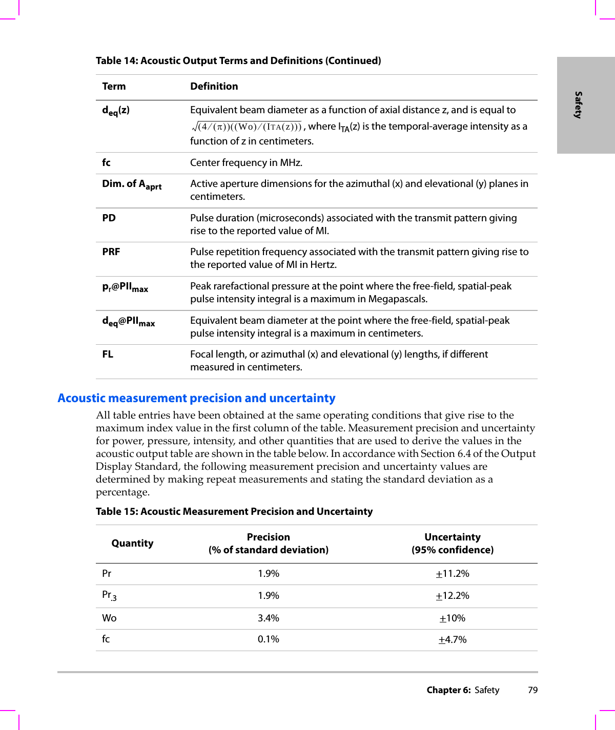
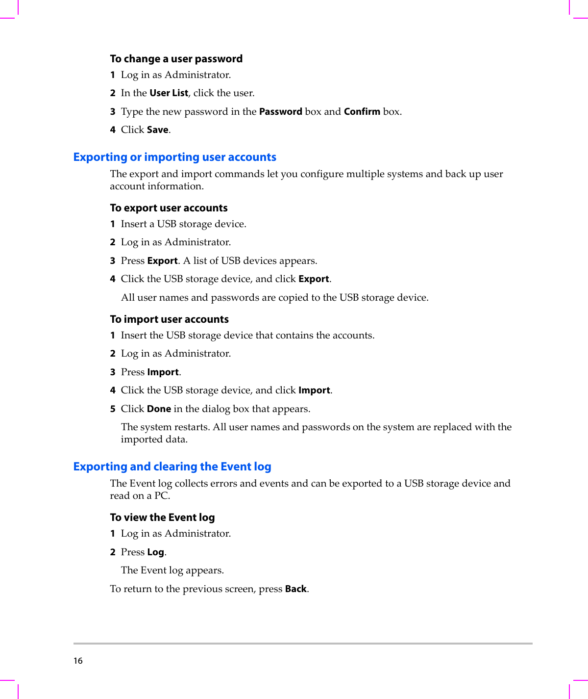
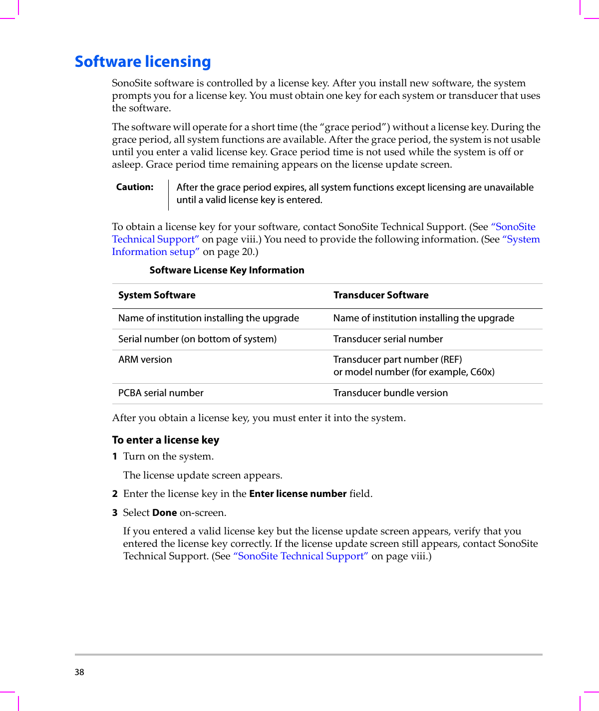
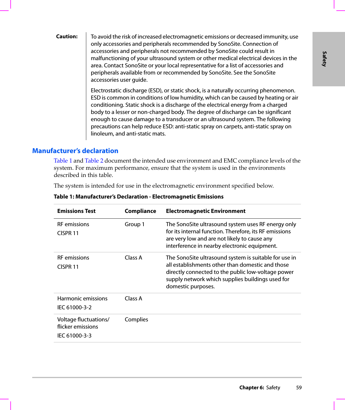
![78 Terms used in the acoustic output tablesTable 14: Acoustic Output Terms and DefinitionsTerm DefinitionISPTA.3 Derated spatial peak, temporal average intensity in units of milliwatts/cm2.TI type Applicable thermal index for the transducer, imaging mode, and exam type.TI value Thermal index value for the transducer, imaging mode, and exam type.MI Mechanical index.Ipa.3@MImax Derated pulse average intensity at the maximum MI in units of W/cm2.TIS (Soft tissue thermal index) is a thermal index related to soft tissues. TIS scan is the soft tissue thermal index in an auto-scanning mode. TIS non-scan is the soft tissue thermal index in the non-autoscanning mode.TIB (Bone thermal index) is a thermal index for applications in which the ultrasound beam passes through soft tissue and a focal region is in the immediate vicinity of bone. TIB non-scan is the bone thermal index in the non-autoscanning mode.TIC (Cranial bone thermal index) is the thermal index for applications in which the ultrasound beam passes through bone near the beam entrance into the body.Aaprt Area of the active aperture measured in cm2.Pr.3 Derated peak rarefactional pressure associated with the transmit pattern giving rise to the value reported under MI (Megapascals).Wo Ultrasonic power, except for TISscan, in which case it is the ultrasonic power passing through a one centimeter window in units of milliwatts.W.3(z1)Derated ultrasonic power at axial distance z1 in units of milliwatts.ISPTA.3(z1)Derated spatial-peak temporal-average intensity at axial distance z1 (milliwatts per square centimeter).z1Axial distance corresponding to the location of maximum [min(W.3(z), ITA.3(z) x 1 cm2)], where z > zbp in centimeters.zbp 1.69 in centimeters.zsp For MI, the axial distance at which pr.3 is measured. For TIB, the axial distance at which TIB is a global maximum (for example, zsp = zb.3) in centimeters.Aaprt()](https://usermanual.wiki/J-Three-Holding/BU2073J.User-Manual-S-Series/User-Guide-1089451-Page-88.png)