JADAK a business unit of Novanta NOVA001 RFID Interrogator User Manual Manual
SkyeTek, Inc RFID Interrogator Manual
UserManual.wiki
>
JADAK a business unit of Novanta
>
NOVA001 User Manual
Manual
Navigation menu
Upload a User Manual
Namespaces
Wiki Guide
HTML
PDF
Info
Views
User Manual
Discussion / Help
Navigation


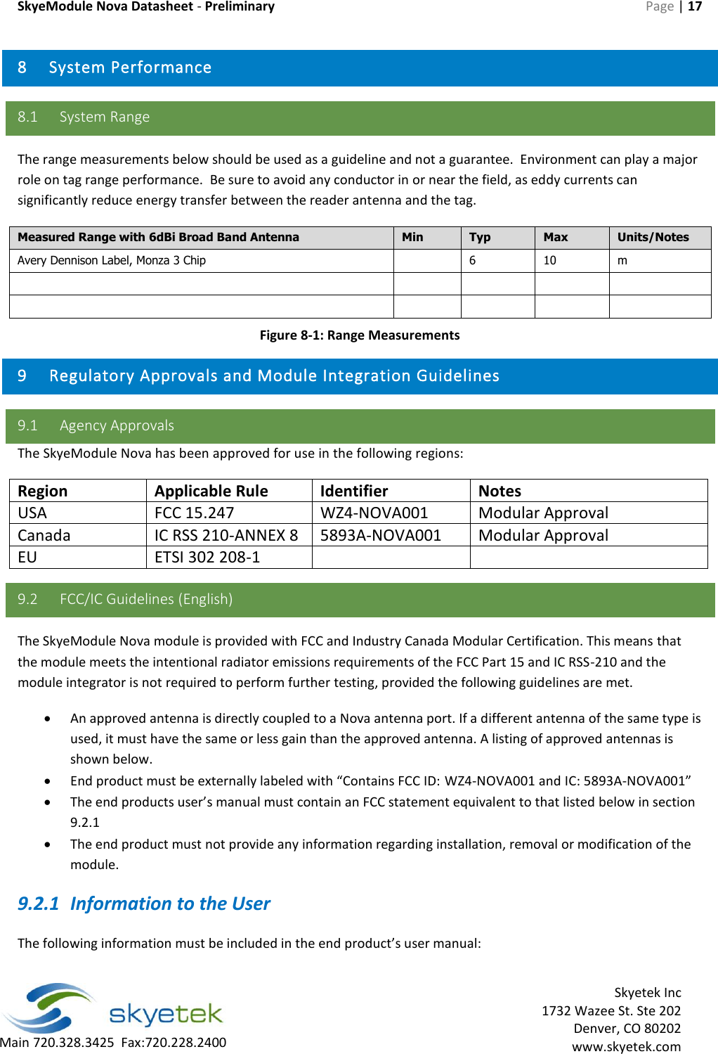


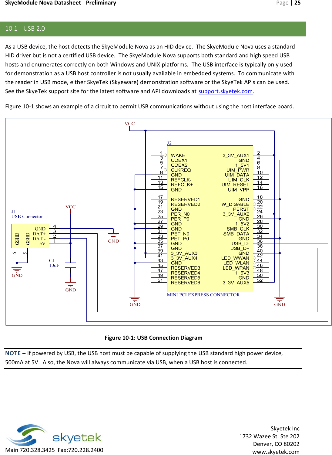
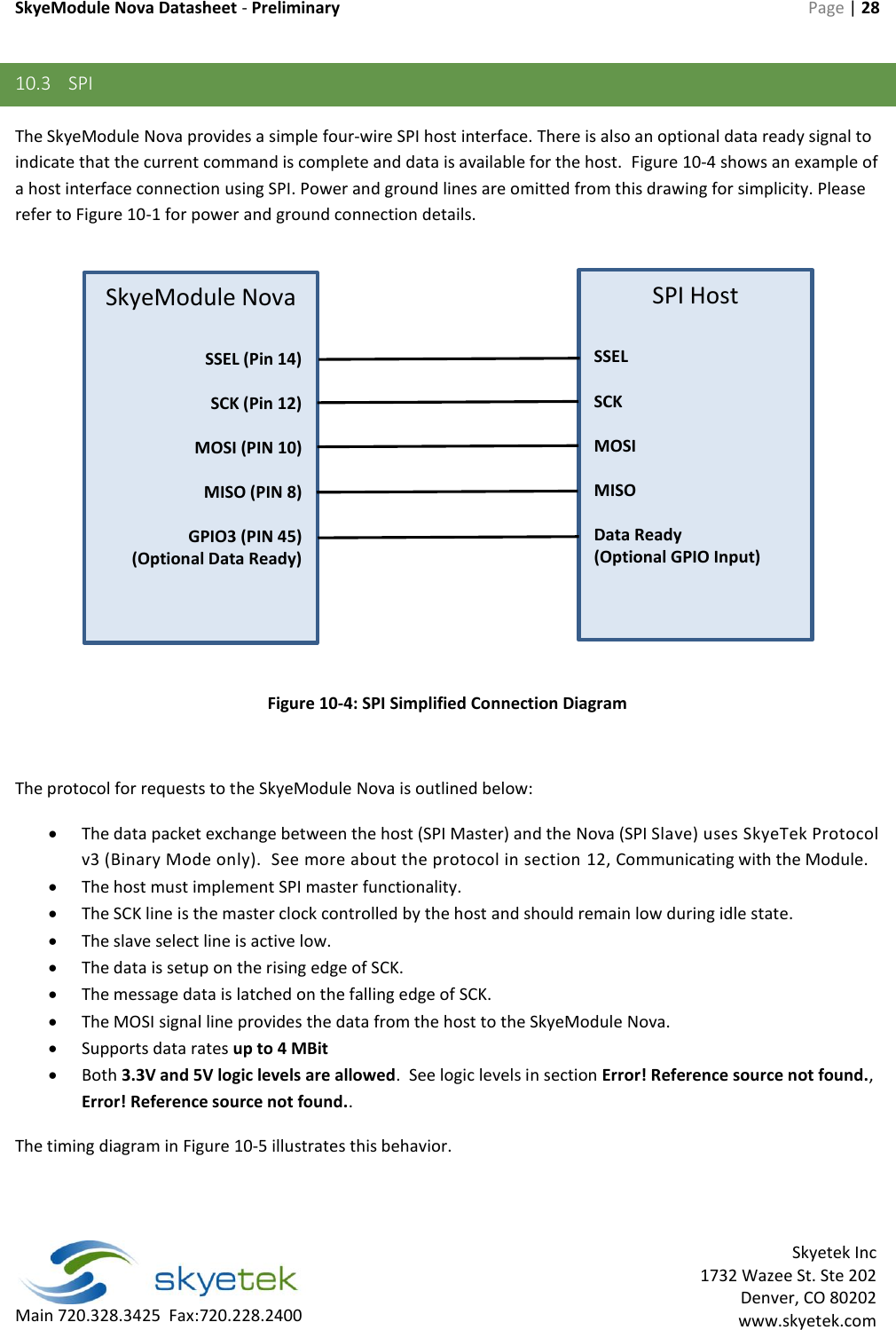
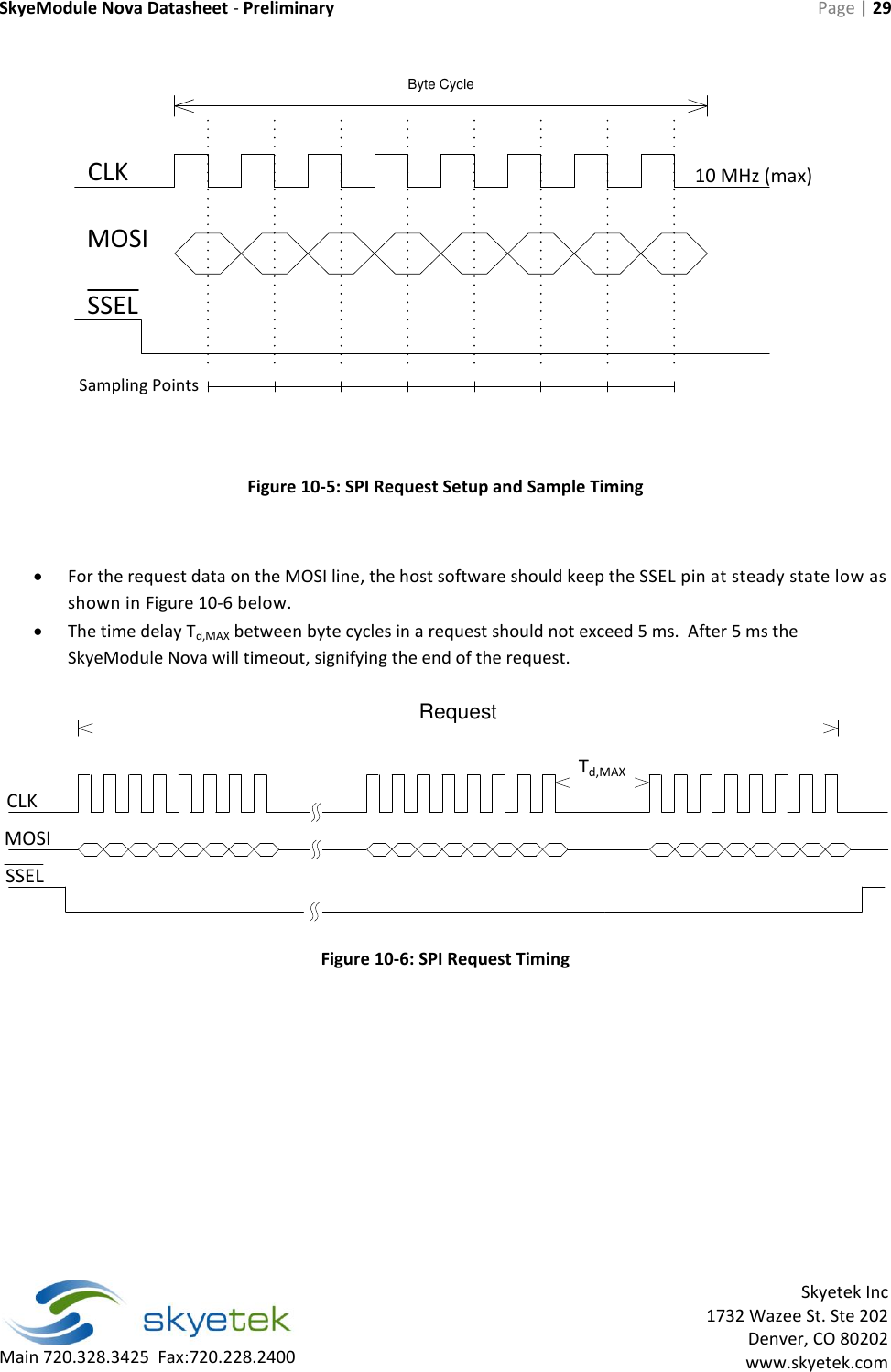
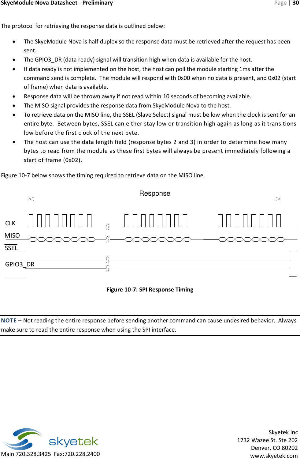
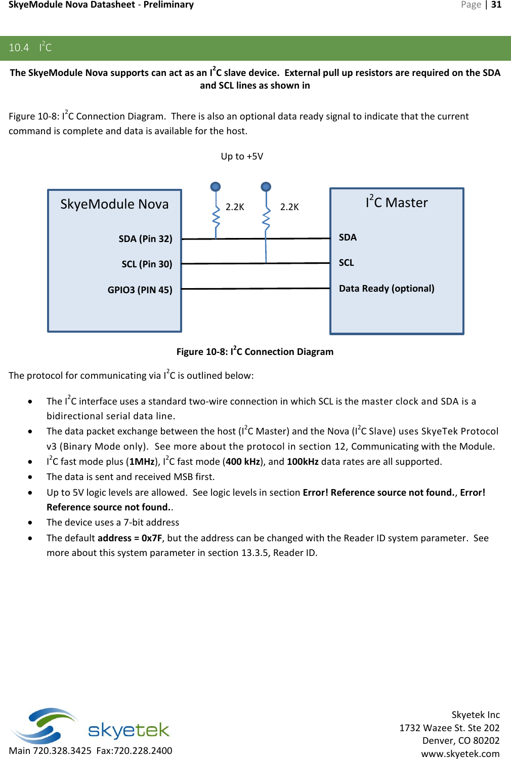
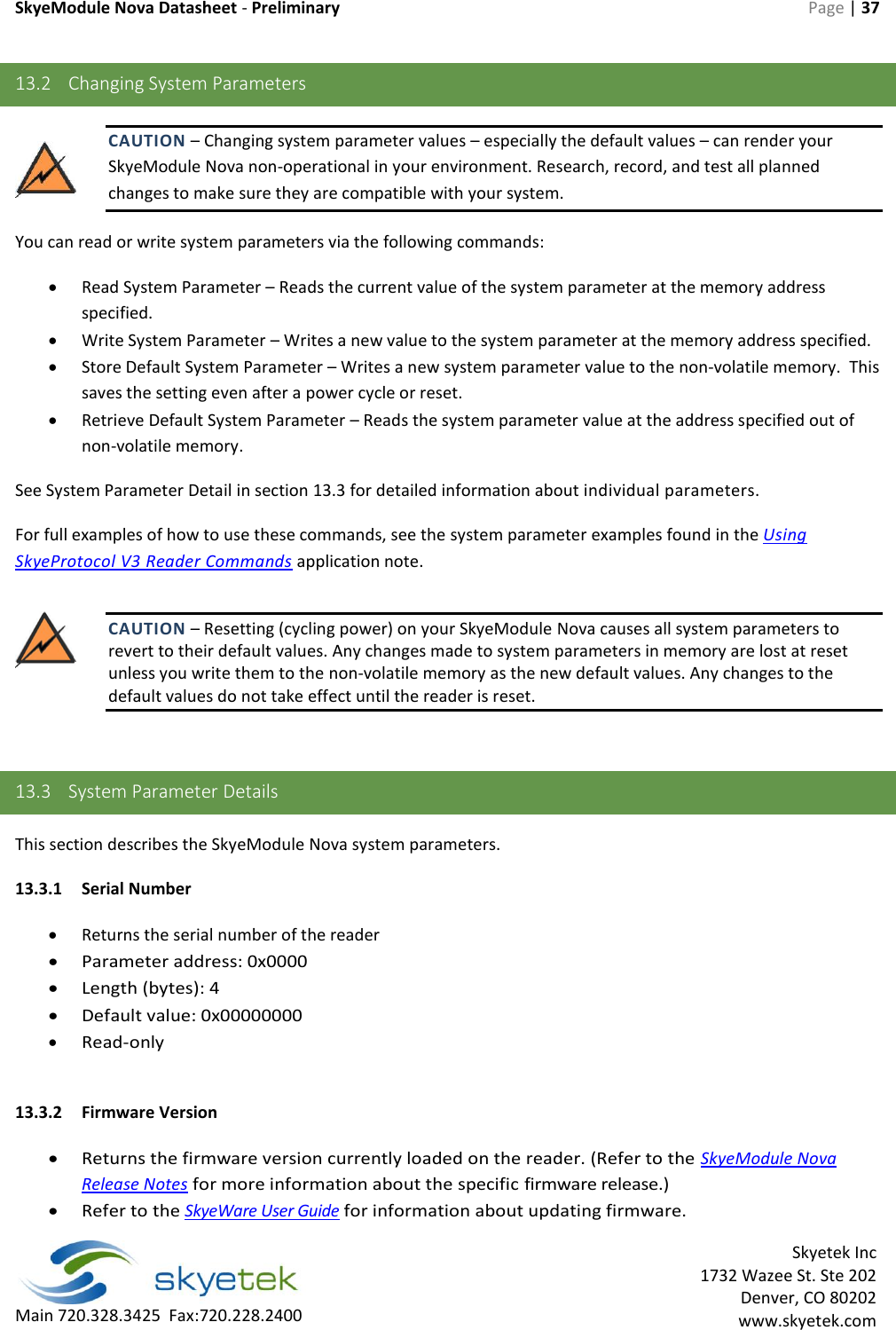
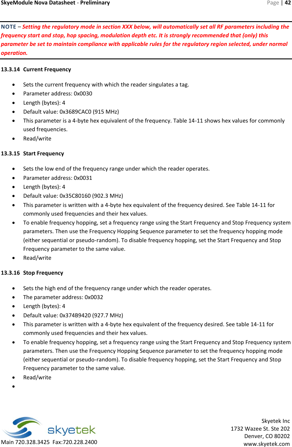
![SkyeModule Nova Datasheet - Preliminary Page | 26 Skyetek Inc 1732 Wazee St. Ste 202 Denver, CO 80202 www.skyetek.com Main 720.328.3425 Fax:720.228.2400 10.2 TTL Serial A two-wire serial connection (no handshaking) is provided on the TXD and RXD lines where TXD and RXD are from the module's point of view. Data exchange between the host and the SkyeModule Nova occurs according to SkyeTek Protocol v3 (ASCII or Binary mode). See more about the protocol in section 12, Communicating with the Module. Serial communication is the most common and robust host interface for this module in an embedded system. Because the interface is asynchronous, the module responds immediately upon command completion instead of waiting for a host clock as in SPI or I 2C. Figure 10-2 shows a sample circuit that lets you connect the SkyeModule Nova without the host interface board. This circuit uses an RS232 to TTL level converter to allow connection to a PC serial port. For direct connection to a micro serial interface (using TTL/CMOS levels), simply connect directly to pins 49 and 51 of the Mini PCI express connector. Figure 10-3 shows examples of typical communication on a signal level. [PICTURE] Figure 10-2: Serial Connection Diagram](https://usermanual.wiki/JADAK-a-business-unit-of-Novanta/NOVA001/User-Guide-2638552-Page-26.png)