JADAK a business unit of Novanta NOVA001 RFID Interrogator User Manual Manual
SkyeTek, Inc RFID Interrogator Manual
Manual
SKYEMODULE NOVA DATASHEET
V1.4

SkyeModule Nova Datasheet - Preliminary Page | 2
Skyetek Inc
1732 Wazee St. Ste 202
Denver, CO 80202
www.skyetek.com
Main 720.328.3425 Fax:720.228.2400
COPYRIGHT INFORMATION:
Copyright 2014 SkyeTek, Inc., 1732 Wazee St. Suite 202, Denver, Colorado 80202, U.S.A. All rights reserved.
Version 031014
This product or document is protected by copyright and distributed under licenses restricting its use, copying, distribution, and decompilation. No part of this
product or document may be reproduced in any form by any means without prior written authorizat ion of SkyeTek and its licensors, if any.
SkyeTek and SkyeWare are trademarks or registered trademarks of SkyeTek, Inc.
MIFARE and NXP is a registered trademark of Royal Philips Electronics.
MicroSoft and Windows are registered trademarks of Microsoft Corporation.
TECHNICAL SUPPORT AND CONTACT
INFORMATION
SkyeTek, Inc.
1732 Wazee St. Suite 202
Denver, CO 80202
http://www.skyetek.com
SALES:
sales@skyetek.com
TECHNICAL SUPPORT:
support@skyetek.com

SkyeModule Nova Datasheet - Preliminary Page | 3
Skyetek Inc
1732 Wazee St. Ste 202
Denver, CO 80202
www.skyetek.com
Main 720.328.3425 Fax:720.228.2400
TABLE OF CONTENTS
1 INTRODUCTION .............................................................................................................................................. 7
1.1 GETTING STARTED .............................................................................................................................................. 7
1.2 WHY A SKYETEK MODULE? .................................................................................................................................. 7
1.3 ADDITIONAL READING ......................................................................................................................................... 8
1.4 REVISION HISTORY .............................................................................................................................................. 8
2 DEFINITION OF TERMS ................................................................................................................................... 8
3 ORDERING INFORMATION ............................................................................................................................. 9
3.1 NOVA STANDARD PART NUMBERS ......................................................................................................................... 9
3.2 HOW TO BUY ..................................................................................................................................................... 9
4 SKYEMODULE NOVA OVERVIEW .................................................................................................................. 10
4.1
D
ESCRIPTION
.................................................................................................................................................. 10
4.2 BLOCK DIAGRAM .............................................................................................................................................. 10
4.3 FEATURES ........................................................................................................................................................ 11
4.4 APPLICATIONS .................................................................................................................................................. 11
4.5 AGENCY APPROVALS ......................................................................................................................................... 12
5 MECHANICAL SPECIFICATIONS ..................................................................................................................... 12
5.1 CONNECTOR DESCRIPTIONS ................................................................................................................................ 13
5.2 HOST INTERFACE CONNECTOR PIN MAPPING ......................................................................................................... 13
5.3 USING THE GPIO PINS ...................................................................................................................................... 14
6 ELECTRICAL SPECIFICATIONS ........................................................................................................................ 15
6.1 ELECTRICAL CHARACTERISTICS ............................................................................................................................. 15
6.2 ABSOLUTE MAXIMUM RATINGS ........................................................................................................................... 16
7 ENVIRONMENTAL SPECIFICATIONS .............................................................................................................. 16
7.1 ELECTROSTATIC PRECAUTIONS ............................................................................................................................. 16
7.2 GENERAL RATINGS AND OPERATING CONDITIONS ................................................................................................... 16
8 SYSTEM PERFORMANCE ............................................................................................................................... 17
8.1 SYSTEM RANGE ................................................................................................................................................ 17
9 REGULATORY APPROVALS AND MODULE INTEGRATION GUIDELINES .......................................................... 17
9.1 AGENCY APPROVALS ......................................................................................................................................... 17
9.2 FCC/IC GUIDELINES (ENGLISH) ........................................................................................................................... 17
9.3 FCC/IC GUIDELINES (FRANÇAIS) ......................................................................................................................... 20
9.4 EU GUIDELINES ................................................................................................................................................ 23
10 HOST INTERFACE SPECIFICATIONS ............................................................................................................ 23
10.1 USB 2.0 ......................................................................................................................................................... 25

SkyeModule Nova Datasheet - Preliminary Page | 4
Skyetek Inc
1732 Wazee St. Ste 202
Denver, CO 80202
www.skyetek.com
Main 720.328.3425 Fax:720.228.2400
10.2 TTL SERIAL ...................................................................................................................................................... 26
10.3 SPI ................................................................................................................................................................ 28
10.4 I2C ................................................................................................................................................................. 31
11 SKYEMODULE NOVA ANTENNA OPTIONS ................................................................................................. 33
12 COMMUNICATING WITH THE MODULE .................................................................................................... 34
12.1 HOST COMMUNICATION (SKYETEK PROTOCOL V3).................................................................................................. 34
12.2 REQUEST FORMATS ........................................................................................................................................... 34
12.3 RESPONSE FORMATS ......................................................................................................................................... 35
13 SYSTEM PARAMETERS .............................................................................................................................. 36
13.1
S
YSTEM
P
ARAMETER
S
UMMARY
.................................................................................................................. 36
13.2 CHANGING SYSTEM PARAMETERS ........................................................................................................................ 37
13.3 SYSTEM PARAMETER DETAILS.............................................................................................................................. 37
14
SPECIAL FEATURES
.................................................................................................................................. 46
14.1 SLEEP MODES .................................................................................................................................................. 46
14.2 FEATURE REQUESTS .......................................................................................................................................... 46

SkyeModule Nova Datasheet - Preliminary Page | 5
Skyetek Inc
1732 Wazee St. Ste 202
Denver, CO 80202
www.skyetek.com
Main 720.328.3425 Fax:720.228.2400
LIST OF FIGURES
Figure 3-1: SkyeTek Part Number Format ..................................................................................................................... 9
Figure 4-1: SM-GM-AC (with all connectors) ............................................................................................................... 10
Figure 4-2: SkyeModule Nova Block Diagram .............................................................................................................. 11
Figure 5-1: SM-GM Mechanical Drawing ..................................................................................................................... 12
Figure 6-1: Host Interface Connector Pin Numbering ................................................................................................. 14
Figure 9-2: Range Specifications .................................................................................................................................. 17
Figure 11-1: USB Connection Diagram ........................................................................................................................ 25
Figure 11-2: TTL Serial Connection Diagram ................................................................................................................ 26
Figure 11-3: TTL Serial Timing Diagram ....................................................................................................................... 27
Figure 11-4: SPI Connection Diagram .......................................................................................................................... 28
Figure 11-5: SPI Request Setup and Sample Timing .................................................................................................... 29
Figure 11-6: SPI Request Timing .................................................................................................................................. 29
Figure 11-7: SPI Response Timing ................................................................................................................................ 30
Figure 11-8: I2C Connection Diagram........................................................................................................................... 31
Figure 11-9: I2C Timing Diagram .................................................................................................................................. 33

SkyeModule Nova Datasheet - Preliminary Page | 6
Skyetek Inc
1732 Wazee St. Ste 202
Denver, CO 80202
www.skyetek.com
Main 720.328.3425 Fax:720.228.2400
LIST OF TABLES
Table 1-1: Revision History ............................................................................................................................................ 8
Table 3-1: Nova Standard Part Numbers ....................................................................................................................... 9
Table 3-2: Part Number Details ..................................................................................................................................... 9
Table 6-1: SkyeModule Nova Connector Specification ................................................................................................ 13
Table 6-2: SkyeModule Nova Pin Descriptions ............................................................... Error! Bookmark not defined.
Table 7-1: Environmental Ratings/Operating Conditions ............................................................................................ 16
Table 8-1: SkyeModule Nova Electrical Specifications ................................................... Error! Bookmark not defined.
Table 8-2: Absolute Maximum Ratings ........................................................................... Error! Bookmark not defined.
Table 13-1: Request Format (bytes), ASCII Mode ........................................................................................................ 34
Table 13-2: Request Format (bytes), Binary Mode ...................................................................................................... 34
Table 13-3: Response Format (bytes), Binary Mode ................................................................................................... 35
Table 14-1: SkyeModule Nova System Parameters ..................................................................................................... 36
Table 14-10: Common Power Values........................................................................................................................... 41
Table 14-11: Commonly Used Frequencies ................................................................................................................. 43
Table 14-12: Common Modulation Depth Values ....................................................................................................... 44
Table 14-13: Regulatory Mode Values......................................................................................................................... 44

SkyeModule Nova Datasheet - Preliminary Page | 7
Skyetek Inc
1732 Wazee St. Ste 202
Denver, CO 80202
www.skyetek.com
Main 720.328.3425 Fax:720.228.2400
1 Introduction
1.1 Getting Started
Operating your SkyeModule Nova begins with finding a method to connect to a host. The SkyeModule itself does
not operate without direction (commands) from a host. The host can be in the form of a PC or, more typically, an
embedded microcontroller. This document explains the physical and electrical characteristics of the module, so
you can understand how to integrate the Nova into a finished product.
For initial demonstration of the module, SkyeWare v4 software is available on the media that came with the
developer/evaluation kit or available for download at support.skyetek.com. Open this software on your windows
PC and it will be recognized when you connect through USB or RS232 (with developer kit interface board). The
software demonstrates features like selecting tags, reading and writing. It also has a powerful command builder
that lets you format, send and receive any command to and from the reader. More about SkyeWare can be found
in the SkyeWare User Guide. See the Additional Reading section below.
The next step after demonstrating the module’s functionality is developing your own communication with the
module. This can be achieved with simple code on a microcontroller or using the SkyeTek API on a PC. Once
connected to a host through one of the four host interfaces, the reader to host communication is formatted with a
full featured protocol called SkyeTek Protocol v3. In order to make learning commands and formatting easy, we
have developed a series of application notes with examples to get you started. The application notes start with
basic tag and reader commands and become very detailed for tags with special features. Read more about the
protocol and commands in section 12, Communicating with the Module and then move on to the Additional
Reading in section 1.3.
1.2 Why a SkyeTek Module?
Many customers may wonder, “What value does a module add over an RFID transceiver chip?”
RFID transceiver chips may seem simple, but they actually require significant engineering time and capital
investment to integrate. Transceiver chips contain up to 50 registers for configuration and functionality. In
addition, communicating over air protocols such as ISO18000-6C is complex, described in nearly 150 pages of
cryptic procedures. For example, just selecting a tag requires a minimum of 6 and up to 100 over air interactions
with multiple tags present. SkyeTek has also optimized the complex RF chain to give the best performance and
efficiency possible. SkyeTek modules mask the complexities of RFID from the user and pack functionality into
just a few commands.
SkyeTek’s core set of commands allow the user to read and write to tags with a single command, regardless of the
tag type. The module is also field upgradable, so you can use the latest security algorithms and tag features as they
are released. Power regulation and filtering for the radio are handled in the Nova, so you can supply voltage
directly from an unregulated source like a battery. Finally, the Nova will be modularly approved by the FCC and CE,
so you can bypass expensive radio testing at a certified test lab and avoid potential schedule delays due to failures.
Using a SkyeTek module will greatly reduce time to market and upfront development costs. Allow SkyeTek to
take the burden of developing an RF system so you can focus your energy on your core products.

SkyeModule Nova Datasheet - Preliminary Page | 8
Skyetek Inc
1732 Wazee St. Ste 202
Denver, CO 80202
www.skyetek.com
Main 720.328.3425 Fax:720.228.2400
1.3 Additional Reading
SkyeTek Protocol v3 Reader Commands – Application note with descriptions and examples of the reader
commands: read/write system, read/write default system, load defaults, and reset.
1.4 Revision History
Revision
Author
Change
031014
Josh Peifer
Initial draft.
Rev 1.0
Mark Matlin
Initial Release
Rev 1.1
Mark Matlin
Added Regulatory Section
Rev 1.2
Mark Matlin
Incorporated TCB changes
Rev 1.3
Mark Matlin
Updated recommended antennas for reverse polarity
Rev 1.4
Mark Matlin
Updated MPE distance to 23cm for IC
Table 1-1: Revision History
2 Definition of Terms
3DES
Triple Data Encryption Standard
AES
Advanced Encryption Standard
API
Application Programming Interface
DES
Data Encryption Standard
GPIO
General Purpose Input/Output
HID
Human Interface Device
I2C
Inter-integrated Circuit
LSB
Least Significant Bit
MSB
Most Significant Bit
NC
No Connect
RoHS
Reduction of Hazardous Substances
SPI
Serial Peripheral Interface
SSEL
Slave Select
STP V3
SkyeTek Protocol Version 3
TTL
Transistor-transistor Logic

SkyeModule Nova Datasheet - Preliminary Page | 9
Skyetek Inc
1732 Wazee St. Ste 202
Denver, CO 80202
www.skyetek.com
Main 720.328.3425 Fax:720.228.2400
3 Ordering Information
3.1 Nova Standard Part Numbers
Part Number
Host Interface
Baud Rate
Description
SM-NV-00
USB (HID)
12Mbps
Mini PCI express connector
Table 3-1: Nova Standard Part Numbers
The Nova part number is constructed according to the SkyeTek part number specification below:
PF-PT-BT-OPTS
Product Family
Product Type
Build Type
Options
Figure 3-1: SkyeTek Part Number Format
Code
Options
Description
Product Family
SM = SkyeModule
Highest level product family code.
Product Type
NV = NOVA
Specifies the specific part type.
Build Type
Specifies hardware form factor.
Options
Blank = Standard
This field is left for special customer part numbers or standard
variations such I2C for I2C as the default host interface. Consult the
SkyeTek sales team for custom orders.
Table 3-2: Part Number Details
3.2 How to Buy
SkyeTek products are available through a worldwide distribution network including Digikey, Mouser and Atlas
RFID. Products are also available directly from SkyeTek. For more information on how to purchase SkyeTek
products in your area, please visit the How To Buy page on the SkyeTek website at www.skyetek.com/howtobuy.
SkyeModule Nova Datasheet - Preliminary Page | 10
Skyetek Inc
1732 Wazee St. Ste 202
Denver, CO 80202
www.skyetek.com
Main 720.328.3425 Fax:720.228.2400
4 SkyeModule Nova Overview
4.1
Description
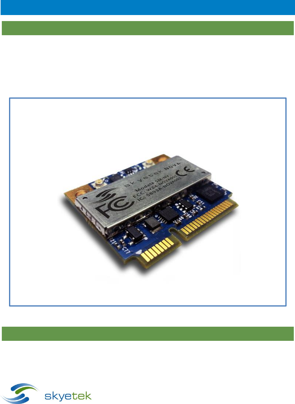
The SkyeModule™ Nova marks the next generation of SkyeTek UHF reader modules. The Nova is an ultra-
small, 2 port, 500mW EPC Class 1 Gen 2 reader/writer module. A cutting edge ARM Cortex microcontroller,
latest UHF transceiver technology and cutting edge adaptive antenna tuning coupled with the reader's
intelligent operating system make this module the most powerful and feature rich UHF reader module of its
size. Manufactured in accordance with ISO 9001 and ISO 13485, quality is a top priority for all SkyeTek
modules.
Figure 4-1: SM-NV
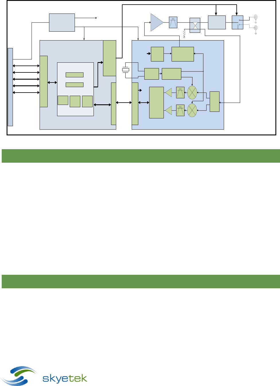
4.2 Block Diagram
SkyeModule Nova Datasheet - Preliminary Page | 11
Skyetek Inc
1732 Wazee St. Ste 202
Denver, CO 80202
www.skyetek.com
Main 720.328.3425 Fax:720.228.2400
Antenna
Tuner
Power
Regulation IN OUT
ISOL
CPLD
ARM CORTEX M0 MICRO
ANT A
PCIe Connector
USB
SPI_0
UART
12C
GPIO(4)
ANT B
RF
Synthesizer
LO I
LO Q
Power
Divider
RX
Detector
and
Framing
Logic
MCU Interface
Clock
Logic
TX
Framing
TX
Modulator
Baseband Filter
TX RF ANT SEL
RX RF
AS3993
Radio IC Drivers
Skye OS
Protocol Parser
Tag Commands
Crypto
Libraries
ISO
Protocol
Libraries
Tag
Feature
Libraries
RF PA
Interface Drivers
TX
TX
Radio Control
Drivers
Vin
RF RF BPF Coupler
Figure 4-2: SkyeModule Nova Block Diagram
4.3 Features
Selects, Reads and writes to transponders based on EPC Global Class 1 Gen 2v2 (ISO 18000-6C)
2 antenna ports, each capable of 500mW output power
Adaptive Antenna Tuning
Can operate from 500mA USB port
Modular certification for USA and Canada
CE Mark
Mini PCIe half card form factor
Wide and efficient power supply with input from 2.5 – 5.5V
Deep sleep mode current down to 10uA
Easy migration from the SkyeModules M7/M9/M10
Supported host interfaces include USB, TTL level RS232, SPI, I2C
Return Signal Strength Indicator (RSSI)
4.4 Applications
Mobile Computing
Inventory and Asset Management
o Retail Inventory
o In Transit Inventory
Access Control
SkyeModule Nova Datasheet - Preliminary Page | 12
Skyetek Inc
1732 Wazee St. Ste 202
Denver, CO 80202
www.skyetek.com
Main 720.328.3425 Fax:720.228.2400
4.5 Agency Approvals
RoHS 2
FCC Modular
IC Modular
CE Mark
UL
Manufactured according to ISO9001 and ISO13485
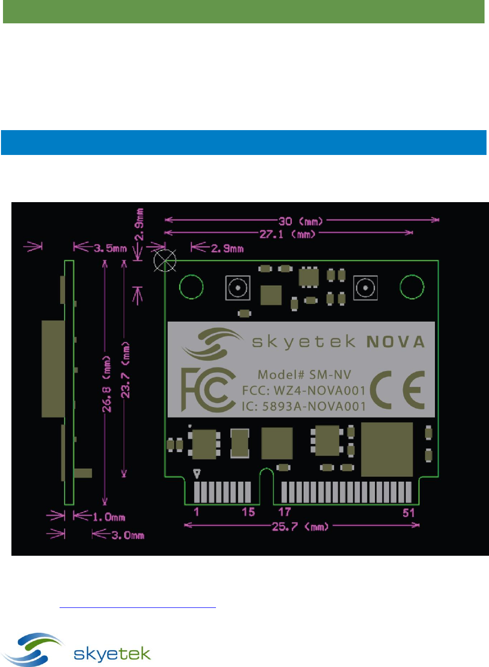
5 Mechanical Specifications
Dimensions: 26.8 mm x 30 mm = 804mm2
Height: 5.5 mm
Figure 5-1: SM-NV Mechanical Drawing
Note that the Nova complies with the PCI Express (PCIe) Mini form factor. Detailed information on this standard is
available at https://www.pcisig.com/specifications. Mating board edge connectors are available from numerous
vendors including JAE, Molex and TE connectivity (see table below). The pin numbering convention is shown in the

SkyeModule Nova Datasheet - Preliminary Page | 13
Skyetek Inc
1732 Wazee St. Ste 202
Denver, CO 80202
www.skyetek.com
Main 720.328.3425 Fax:720.228.2400
drawing above, with odd numbered pins on the top, and even numbered pins on the bottom of the board. Pin 2 is
directly below pin 1. Pinning Information
5.1 Connector Descriptions
The SM-NV-00 is the standard version of the Nova module and uses the 52 pin Mini PCIe connector In addition, the
Nova features two antenna ports that connect via U.FL connectors. A sampling of mating connectors is listed
below:
Nova Connector
Description
Ref Des
Man.
Mating Connector
Notes
52 pin Mini PCIe
Host interface
connector
J1
Molex
0679101002
JAE
MM60-52B1-G1-R850
TE Connectivity
1717831-1
U.FL Jack
Antenna Connector
(Port0, Port1)
J2, J3
Taoglas
CAB.011
U.FL to SMA
Digi International
JF1R6-CR3041
U.FL to SMA
Table 5-1: SkyeModule Nova Connector Recommendations
5.2 Host Interface Connector Pin Mapping
The SkyeModule Nova host connector is a 52-pin Mini PCI Express edge connector. The pin numbers are located as
illustrated in Figure 5-2 above. The pin mappings and descriptions are shown in Error! Reference source not
found.. Note that all unconnected pins should be left floating.

SkyeModule Nova Datasheet - Preliminary Page | 14
Skyetek Inc
1732 Wazee St. Ste 202
Denver, CO 80202
www.skyetek.com
Main 720.328.3425 Fax:720.228.2400
Figure 5-2: Host Interface Connector Pin Numbering
Pin
Name
Description
I/O
Pin
Name
Description
I/O
1
NC
Not Connected
N/A
2
VIN
Input Power Supply
Input
3
NC
Not Connected
N/A
4
GND
Ground
Input
5
NC
Not Connected
N/A
6
NC
Not Connected
N/A
7
NC
Not Connected
N/A
8
MISO
SPI Master In, Slave Out
Output
9
GND
Ground
Input
10
MOSI
SPI Master Out, Slave In
Input
11
NC
Not Connected
N/A
12
SCK
SPI Clock IN
Input
13
NC
Not Connected
N/A
14
SSEL
SPI Slave Select
Input
15
GND
Ground
Input
16
NC
Not Connected
N/A
17
NC
Not Connected
N/A
18
GND
Ground
Input
19
NC
Not Connected
N/A
20
Deep Sleep
Active Low Deep Sleep
Input
21
GND
Ground
Input
22
Reset
Active Low Reset
Input
23
NC
Not Connected
N/A
24
VIN
Input Power Supply
Input
25
NC
Not Connected
N/A
26
GND
Ground
Input
27
GND
Ground
Input
28
NC
Not Connected
N/A
29
GND
Ground
Input
30
SCL
I2C Clock
Input
31
NC
Not Connected
N/A
32
SDA
I2C Data
I/O
33
NC
Not Connected
N/A
34
GND
Ground
Input
35
GND
Ground
Input
36
D-
USB D minus
I/O
37
GND
Ground
Input
38
D +
USB D Plus
I/O
39
VIN
Input Power Supply
Input
40
GND
Ground
Input
41
VIN
Input Power Supply
Input
42
GPIO0
General Purpose I/O 0
I/O
43
GND
Ground
Input
44
GPIO1
General Purpose I/O 1
I/O
45
GPIO3
General Purpose I/O 3
I/O
46
GPIO2
General Purpose I/O 2
I/O
47
NC
Not Connected
N/A
48
NC
Not Connected
N/A
49
RXD
UART Receive
Input
50
GND
Ground
Input
51
TXD
UART Transmit
Output
52
VIN
Input Power Supply
Input
5.3 Using the GPIO Pins
You can use the User Port Direction and User Port Value system parameters to address the GPIO pins to set
the user port direction (input or output) and the user port value (high or low). For more information, see
the following:
“User Port Direction” in section 13.3.9
“User Port Value” in section 13.3.10
NOTE – GPIO3 is used as a data ready pin when in SPI or I2C mode. GPIO3 cannot be used as GPIO when using
these interfaces.

SkyeModule Nova Datasheet - Preliminary Page | 15
Skyetek Inc
1732 Wazee St. Ste 202
Denver, CO 80202
www.skyetek.com
Main 720.328.3425 Fax:720.228.2400
6 Electrical Specifications
This chapter discusses the electrical specifications of the SkyeModule Nova. Unless otherwise noted, the following
assumptions apply to these specifications:
Temperature is 25 degrees Celsius.
Frequency is 915 MHz.
Supply voltage (VCC) is 5 V.
6.1 Electrical Characteristics
Specification
Min
Typ
Max
Units/Notes
RF Characteristics
Frequency range (Direct output)
860-960
MHz
Transmit Parameters
RF Transmit Output Power (Peak)
500
mW (27dBm)
RF Transmit Output Power Adjustment Range
17
10dBm - 27dBm
Transmit Power Adjustment Accuracy
+/- 1
+/- 2.5
dBm
Optimum PA Load Impedance
50
Ohms
Antenna Tuning Range
1.5:1
VSWR
Receive Parameters
Receive Sensitivity
-85
dBm
Logic Inputs
High state input voltage
2.3
5.0
V
Low state input voltage
0
1
V
Input Current (IINH/IINL)
10
nA
Logic Outputs
Output High Voltage (VOH)
2.8
3.3
3.6
V (IOH=4Ma)
Output Low Voltage (VOL)
0
0.4
V (IOH=-4mA)
Output Current (IINH/IINL)
+/- 4
mA
Power Supplies
Voltage Supply
2.5
5.5
V
Idle Current @ 5V Supply
155
mA
Continuous Transmit Current @ 5V Supply
450
mA
Low Power Software Sleep Mode Current @ 5V Supply
10
mA
Deep Sleep Mode Current @ 5V Supply
5
uA
Table 6-1: SkyeModule Nova Electrical Specifications
SkyeModule Nova Datasheet - Preliminary Page | 16
Skyetek Inc
1732 Wazee St. Ste 202
Denver, CO 80202
www.skyetek.com
Main 720.328.3425 Fax:720.228.2400
6.2 Absolute Maximum Ratings
Specification
Rating
VSUPPLY to GND
7.0 V
Digital I/O voltage to GND
5.5 V
Table 6-2: Absolute Maximum Ratings
7 Environmental Specifications
7.1 Electrostatic Precautions
CAUTION – Failure to take proper electrostatic precautions may result in damage to or failure of your
SkyeModule Nova.
The SkyeModule Nova contains static-sensitive parts. Observe the following precautions to prevent damage to
these parts.
Wear a static grounding strap when handling electronic control components.
Keep all plastic, vinyl, and Styrofoam (except antistatic versions) away from printed circuit boards.
Do not touch the components or conductors on a printed circuit board with your hands or with
conductive devices.
7.2 General Ratings and Operating Conditions
Specification
Rating
Temperature range
Operating
-20 to +70 degrees C
Storage
-40 to +125 degrees C
Humidity
Operating, continuous storage
10-90 percent (non-condensing)
Transient storage (<24 hours)
5-95 percent maximum (non-condensing)
ESD protection
< 1kV (ESD HBM 15500 Ω, 100pF) —or—
100V (ESD MM 0.75uH, 200pF)
Table 7-1: Environmental Ratings/Operating Conditions

SkyeModule Nova Datasheet - Preliminary Page | 17
Skyetek Inc
1732 Wazee St. Ste 202
Denver, CO 80202
www.skyetek.com
Main 720.328.3425 Fax:720.228.2400
8 System Performance
8.1 System Range
The range measurements below should be used as a guideline and not a guarantee. Environment can play a major
role on tag range performance. Be sure to avoid any conductor in or near the field, as eddy currents can
significantly reduce energy transfer between the reader antenna and the tag.
Measured Range with 6dBi Broad Band Antenna
Min
Typ
Max
Units/Notes
Avery Dennison Label, Monza 3 Chip
6
10
m
Figure 8-1: Range Measurements
9 Regulatory Approvals and Module Integration Guidelines
9.1 Agency Approvals
The SkyeModule Nova has been approved for use in the following regions:
Region
Applicable Rule
Identifier
Notes
USA
FCC 15.247
WZ4-NOVA001
Modular Approval
Canada
IC RSS 210-ANNEX 8
5893A-NOVA001
Modular Approval
EU
ETSI 302 208-1
9.2 FCC/IC Guidelines (English)
The SkyeModule Nova module is provided with FCC and Industry Canada Modular Certification. This means that
the module meets the intentional radiator emissions requirements of the FCC Part 15 and IC RSS-210 and the
module integrator is not required to perform further testing, provided the following guidelines are met.
An approved antenna is directly coupled to a Nova antenna port. If a different antenna of the same type is
used, it must have the same or less gain than the approved antenna. A listing of approved antennas is
shown below.
End product must be externally labeled with “Contains FCC ID: WZ4-NOVA001 and IC: 5893A-NOVA001”
The end products user’s manual must contain an FCC statement equivalent to that listed below in section
9.2.1
The end product must not provide any information regarding installation, removal or modification of the
module.
9.2.1 Information to the User
The following information must be included in the end product’s user manual:

FCC / IC NOTICES
This product contains FCC ID: WZ4-NOVA001 / IC: 5893A-NOVA001. This device complies with
Part 15 of the FCC rules and Industry Canada license-exempt RSS standards. Operation of this
device is subject to the
following two conditions:
1. This device may not cause harmful interference, and
2. This device must accept any interference received, including interference that may
cause undesired operation.
This equipment has been tested and found to comply with the limits for a Class B digital device,
pursuant to Part 15 of the FCC Rules. These limits are designed to provide reasonable protection
against harmful interference in a residential installation. This equipment generates, uses and can
radiate radio frequency energy and, if not installed and used in accordance with the instructions,
may cause harmful interference to radio communications. However, there is no guarantee that
interference will not occur in a particular installation. If this equipment does cause harmful
interference to radio or television reception, which can be determined by turning the equipment
off and on, the user is encouraged to try to correct the interference by one or more of the
following measures:
• Reorient or relocate the receiving antenna.
• Increase the separation between the equipment and receiver.
• Connect the equipment into an outlet on a circuit different from that to which
the receiver is connected.
• Consult the dealer or an experienced radio/TV technician for help.
Any modifications could void the user’s authority to operate the equipment.

9.2.2 Product Labeling
The end product must be labeled to meet the FCC and IC product label requirements. It must have text containing
the following:
Contains FCC ID: WZ4-NOVA001 / IC: 5893A-NOVA001
The label must be permanently affixed to the product and readily visible to the user. ‘‘Permanently affixed’’ means
that the label is etched, engraved, stamped, silkscreened, indelibly printed, or otherwise permanently marked on a
permanently attached part of the equipment or on a nameplate of metal, plastic, or other material fastened to the
equipment by welding, riveting, or a permanent adhesive. The label must be designed to last the expected lifetime
of the equipment in the environment in which the equipment may be operated and must not be readily
detachable.
9.2.3 RF Exposure Statement
To comply with FCC’s RF radiation exposure requirements, this device and its antenna(s) must operate at a
distance of at least 20cm from all persons, and must not be co-located or operating in conjunction with any other
antenna or transmitter.
To comply with IC’s RF radiation exposure requirements, this device, when operated with the Linearly Polarized
Panel or Circularly Polarized Panel antenna listed below, or any similar high gain panel antenna, must maintain a
separation distance of at least 23cm from all persons, and must not be co-located or operating in conjunction with
any other antenna or transmitter. To comply with IC’s RF radiation exposure requirements, this device, when
operated with all antennas, must maintain a separation distance of at least 20cm from all persons, and must not
be co-located or operating in conjunction with any other antenna or transmitter.
9.2.4 Antenna Selection
IC Statement:
This radio transmitter (5893A-NOVA001) has been approved by Industry Canada to operate with the antenna types
listed below with the maximum permissible gain indicated. Antenna types not included in this list, having a gain
greater than the maximum gain indicated for that type, are strictly prohibited for use with this device.
As part of the Modular Certification, the SkyeModule Nova was tested and approved for use with the following
antennas. All of these antennas incorporate connectors that are “non-standard” per FCC 15.203.
Antenna Type
Peak Gain
Manufacturer
P/N
Connector
Linearly Polarized Panel
9dBi
Laird
PAV90209-HFRTN
RP-TNC
Circularly Polarized Panel
9dBi
Laird
PAL90209H-HFRTN
RP-TNC
Dipole
5.4dBi
Linx Technologies
ANT-916-MHW-RPS-S
RP-SMA
Planar Inverted F (PIFA)
2dBi
Proprietary
Proprietary
U.FL
Under FCC and Industry Canada regulations, the SkyeModule Nova may only operate using an antenna type and
maximum (or lesser) gain than that approved for these antennas by the FCC and Industry Canada.

SkyeModule Nova Datasheet - Preliminary Page | 20
Skyetek Inc
1732 Wazee St. Ste 202
Denver, CO 80202
www.skyetek.com
Main 720.328.3425 Fax:720.228.2400
Other antennas types may be used, however they will not be recognized under this Modular Certification and
additional regulatory testing will be necessary. In all cases, the maximum total gain (antenna + cable) permissible
for use with the SkyeModule Nova will be 9dBi, which achieves the maximum field strength permitted by the FCC
in the 902 – 928 MHz ISM band.
The Nova module is provided with a U.FL connector which has been determined to be “non-standard” complying
with FCC 15.203. Any antenna connection which is available to the end user must be “non-standard” so that user
may not easily connect a higher gain antenna than is permissible above.
9.2.5 Unintentional Radiator Testing
The SkyeModule Nova module was tested to and complies with the unintentional radiator requirements of FCC
sections 15.107 and 15.109 and Industry Canada license exempt RSS standards. When integrated within final
product, additional unintentional radiator testing may be required.
9.3 FCC/IC Guidelines (Français)
Le module SkyeModule Nova est fourni avec FCC et Industrie Canada modulaire certification. Cela signifie que le
module répond aux exigences d'émissions intentionnelles de radiateur de la FCC Part 15 et IC RSS-210 et le module
intégrateur ne est pas nécessaire d'effectuer des tests supplémentaires, à condition que les lignes directrices
suivantes sont remplies.
Une antenne approuvé est couplé directement à un port d'antenne Nova. Si une autre antenne du même
type est utilisé, il doit avoir le même ou moins de gain de l'antenne approuvé. Une liste des antennes
approuvés est indiqué ci-dessous.
Le produit final doit être étiqueté avec l'extérieur "Contient FCC ID: WZ4-NOVA001 et IC: 5893A-
NOVA001"
Le manuel de l'utilisateur des produits finis doivent contenir une déclaration de la FCC équivalent à celui
ci-dessous dans la section 9.3.1
e manuel de L'Utilisateur des Produits finis doivent contain Une déclaration de la FCC équivalent à celui ci-
dessous Dans la section 9.3.1
9.3.1 Informations utilisateur
Les renseignements suivants doivent être inclus dans le manuel d'utilisation de produit de fin :

AVIS FCC / IC
Ce produit contient FCC ID: WZ4-NOVA001 / IC: 5893A-NOVA001. Cet appareil
est conforme à la partie 15 des règles de la FCC et d'Industrie Canada RSS
normes exemptes de licence. Le fonctionnement de cet appareil est soumis à la
deux conditions suivantes:
1. Ce dispositif ne doit pas causer d'interférences nuisibles et
2. Cet appareil doit accepter toute interférence reçue, y compris les interférences
qui peuvent causer un mauvais fonctionnement.
Cet équipement a été testé et déclaré conforme aux limites d'un appareil
numérique de classe B, conformément à la partie 15 des règles de la FCC. Ces
limites sont conçues pour fournir une protection raisonnable contre les
interférences nuisibles dans une installation résidentielle. Cet équipement
génère, utilise et peut émettre de l'énergie radiofréquence et, se il ne est pas
installé et utilisé conformément aux instructions, peut causer des interférences
nuisibles aux communications radio. Cependant, il ne est pas garanti que des
interférences ne se produiront pas dans une installation particulière. Si cet
équipement provoque des interférences nuisibles à la réception radio ou de
télévision, ce qui peut être déterminé en mettant l'équipement hors et sous
tension, l'utilisateur est encouragé à essayer de corriger l'interférence par une
ou plusieurs des mesures suivantes:
• Réorienter ou déplacer l'antenne de réception.
• Augmentez la distance entre l'équipement et le récepteur.
• Branchez l'appareil dans une prise sur un circuit différent de celui sur lequel
le récepteur est branché.
• Consulter le revendeur ou un technicien radio / TV expérimenté.
Toute modification peut annuler le droit de l'utilisateur à utiliser l'équipement.

9.3.2 Étiquetage de produit
Le produit final doit être étiqueté pour répondre aux exigences de l'étiquette du produit FCC et IC. Il doit avoir le
texte contenant les éléments suivants:
Contains FCC ID: WZ4-NOVA001 / IC: 5893A-NOVA001
L'étiquette doit être apposée en permanence sur le produit et facilement visible pour l'utilisateur. '' Fixé en
permanence '' signifie que l'étiquette est gravé, gravé, estampé, sérigraphié, indélébile, ou autrement de façon
permanente sur une partie fixée de façon permanente de l'équipement ou sur une plaque de métal, de plastique,
ou autre matériau fixé à l'équipement par soudage, rivetage ou d'un adhésif permanent. L'étiquette doit être
conçu pour durer toute la durée de vie prévue de l'équipement dans l'environnement dans lequel l'équipement
peut être utilisé et ne doit pas être facilement détachable.
9.3.3 Déclaration d'exposition aux RF
Pour se conformer à l'exposition aux rayonnements RF aux exigences de la FCC, cet appareil et son antenne (s) doit
fonctionner à une distance d'au moins 20 cm de toutes les personnes, et ne doit pas être co-située ni fonctionner
en conjonction avec une autre antenne ou émetteur.
Pour se conformer à exposition aux radiations RF les exigences d'IC, cet appareil, en cas d'utilisation avec le
panneau polarisé linéairement ou antenne Panneau polarisée circulairement énumérés ci-dessous, ou de toute
antenne similaire panel de haut gain, doit maintenir une distance de séparation d'au moins 23cm de toutes les
personnes, et doit pas être co-située ni fonctionner en conjonction avec une autre antenne ou émetteur.
9.3.4 Antenne Sélection
Cet émetteur radio (5893A-NOVA001) a été approuvé par Industrie Canada pour fonctionner avec les types
d'antenne énumérés ci-dessous avec le gain maximal admissible indiquée. Types d'antennes ne figurant pas dans
cette liste, ayant un gain supérieur au gain maximum indiqué pour ce type, sont strictement interdits pour une
utilisation avec cet appareil.
Antenna Type
Peak Gain
Manufacturer
P/N
Connector
Linearly Polarized Panel
9dBi
Laird
PAV90209-HFRTN
RP-TNC
Circularly Polarized Panel
9dBi
Laird
PAL90209H-HFRTN
RP-TNC
Dipole
5.4dBi
Linx Technologies
ANT-916-MHW-RPS-S
RP-SMA
Planar Inverted F (PIFA)
2dBi
Proprietary
Proprietary
U.FL
En vertu des règlements de la FCC et d'Industrie Canada, la Nouvelle-SkyeModule ne peut fonctionner en utilisant
un type et maximum (ou moins) antenne à gain approuvé pour l'émetteur par la FCC et d'Industrie Canada.
Autres types d'antennes peuvent être utilisés, mais ils ne seront pas reconnus en vertu du présent certification
modulaire et essais réglementaires supplémentaires seront nécessaires. Dans tous les cas, le gain total maximum
(antenne + câble) autorisé pour une utilisation avec la Nouvelle-SkyeModule sera 9dBi, qui réalise l'intensité de
champ maximale permise par la FCC dans le 902 - 928 MHz bande ISM.

SkyeModule Nova Datasheet - Preliminary Page | 23
Skyetek Inc
1732 Wazee St. Ste 202
Denver, CO 80202
www.skyetek.com
Main 720.328.3425 Fax:720.228.2400
9.3.5 Test radiateur involontaire
Le module a été testé SkyeModule Nouvelle et qui se conforme aux exigences de radiateur involontaires de
sections FCC 15,107 et 15,109 et licences Industrie Canada RSS exemptés normes. Lorsqu'il est intégré au sein de
produit final, des tests supplémentaires de radiateur involontaire peut être nécessaire.
9.4 EU Guidelines
The SkyeModule Nova was tested to the standards defined by ETSI 302 208-1 (Electromagnetic compatibility
and Radio spectrum Matters; Radio Frequency Identification Equipment operating in the band 865 MHz to 868
MHz with power levels up to 2 W).
In order to market and sell product in the European markets, manufacturers need to demonstrate compliance
using a Declaration of Conformity. Unlike the United States, there is no certification process through a regulating
body. Instead, manufacturers have the sole responsibility of ensuring their products are compliant to the
applicable directives and standards.
Also, unlike the USA and Canada, there are no “Modular Approval” rules under the ETSI standards, and the
integrator must either declare conformity of the entire system based on the testing of the module, or perform
additional testing with the complete integrated system including antenna(s). Since conducted testing was
performed with the module, it is straightforward to show compliance with a particular antenna based on its
radiation characteristics. Upon request, Skyetek will provide ETSI test data and reports as necessary to aid in
showing compliance to the ETSI standards when the Nova is integrated within the final product. Skyetek can also
provide it’s Declaration of Conformity (DoC), if requested. In addition, Skyetek engineers are available to assist in
EU compliance matters.
10 Host Interface Specifications
The SkyeModule Nova supports the following microcontroller host interfaces for easy integration into existing
systems:
USB (Overrides other interfaces when connected)
TTL Serial
SPI
I2C
The SkyeModule Nova and the host interface board support TTL Serial and USB communications. The host
interface board provides a USB connector and a TTL to RS-232 level converter for the TTL Serial host interface. The
Host Interface system parameter determines which host interface is used for communication with the host.
Each interface is software selectable and only one host interface is active at a time, however, USB may
always be connected and overrides the current interface. The host interface is selected based on the

SkyeModule Nova Datasheet - Preliminary Page | 24
Skyetek Inc
1732 Wazee St. Ste 202
Denver, CO 80202
www.skyetek.com
Main 720.328.3425 Fax:720.228.2400
power-up default value and can be changed at run time. The SkyeModule Nova operates under host control
using SkyeTek Protocol v3 sent over one of the host interfaces described in this chapter.
The following sections describe the power and host communication connections for the SkyeModule Nova. The
SkyeTek Protocol and commands are described further in section 12, Communicating with the Module.
SkyeModule Nova Datasheet - Preliminary Page | 25
Skyetek Inc
1732 Wazee St. Ste 202
Denver, CO 80202
www.skyetek.com
Main 720.328.3425 Fax:720.228.2400
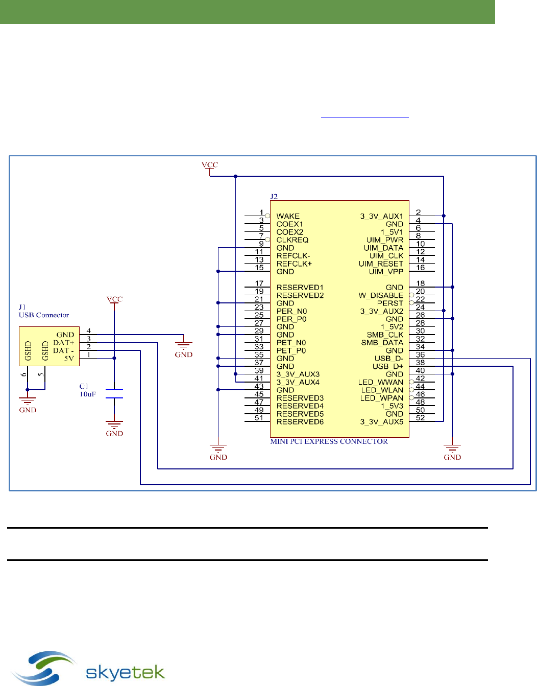
10.1 USB 2.0
As a USB device, the host detects the SkyeModule Nova as an HID device. The SkyeModule Nova uses a standard
HID driver but is not a certified USB device. The SkyeModule Nova supports both standard and high speed USB
hosts and enumerates correctly on both Windows and UNIX platforms. The USB interface is typically only used
for demonstration as a USB host controller is not usually available in embedded systems. To communicate with
the reader in USB mode, either SkyeTek (Skyeware) demonstration software or the SkyeTek APIs can be used.
See the SkyeTek support site for the latest software and API downloads at support.skyetek.com.
Figure 10-1 shows an example of a circuit to permit USB communications without using the host interface board.
Figure 10-1: USB Connection Diagram
NOTE – If powered by USB, the USB host must be capable of supplying the USB standard high power device,
500mA at 5V. Also, the Nova will always communicate via USB, when a USB host is connected.
SkyeModule Nova Datasheet - Preliminary Page | 26
Skyetek Inc
1732 Wazee St. Ste 202
Denver, CO 80202
www.skyetek.com
Main 720.328.3425 Fax:720.228.2400
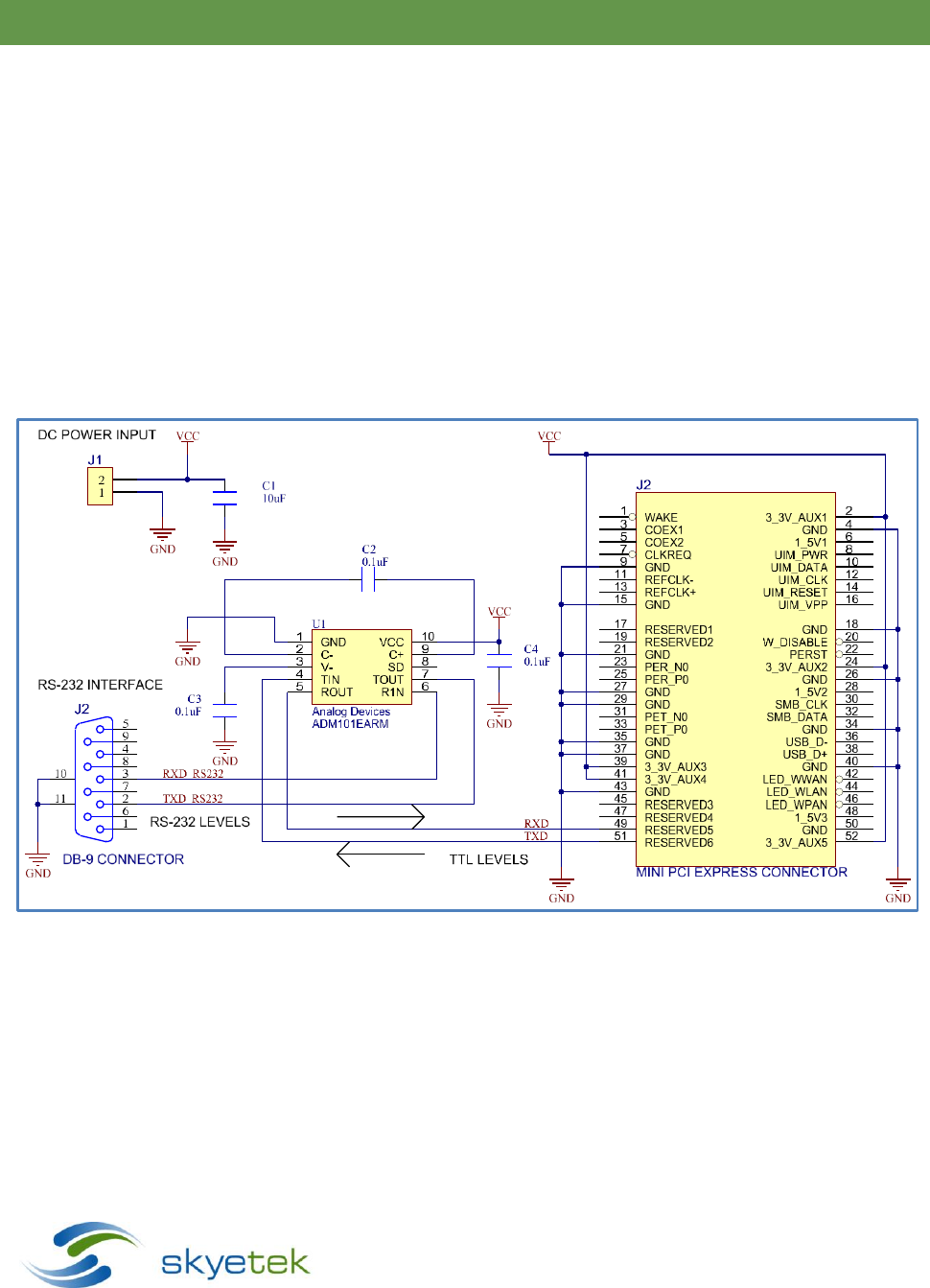
10.2 TTL Serial
A two-wire serial connection (no handshaking) is provided on the TXD and RXD lines where TXD and RXD are from
the module's point of view. Data exchange between the host and the SkyeModule Nova occurs according to
SkyeTek Protocol v3 (ASCII or Binary mode). See more about the protocol in section 12, Communicating with
the Module.
Serial communication is the most common and robust host interface for this module in an embedded
system. Because the interface is asynchronous, the module responds immediately upon command
completion instead of waiting for a host clock as in SPI or I 2C.
Figure 10-2 shows a sample circuit that lets you connect the SkyeModule Nova without the host interface board.
This circuit uses an RS232 to TTL level converter to allow connection to a PC serial port. For direct connection to a
micro serial interface (using TTL/CMOS levels), simply connect directly to pins 49 and 51 of the Mini PCI express
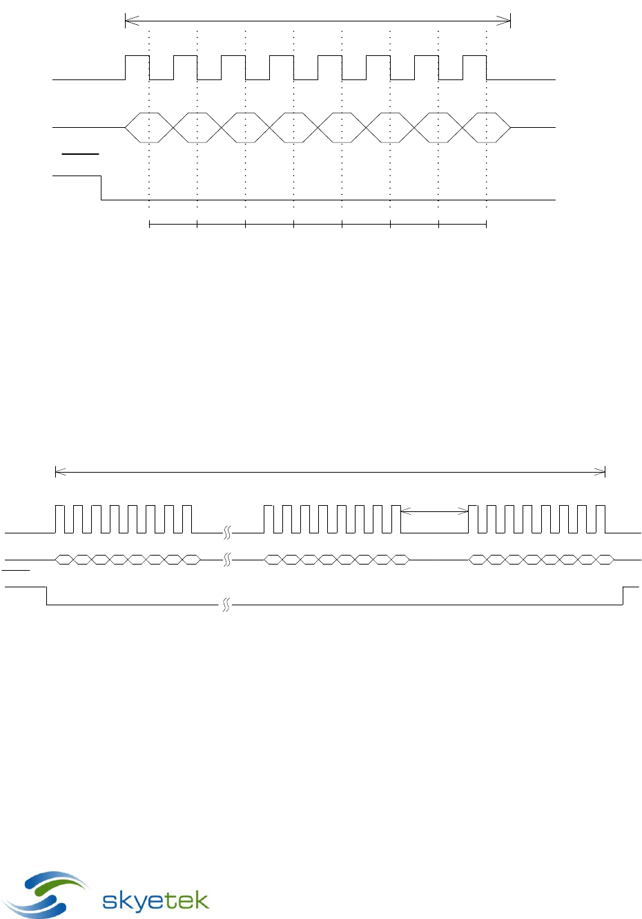
connector. Figure 10-3 shows examples of typical communication on a signal level.
[PICTURE]
Figure 10-2: Serial Connection Diagram

SkyeModule Nova Datasheet - Preliminary Page | 27
Skyetek Inc
1732 Wazee St. Ste 202
Denver, CO 80202
www.skyetek.com
Main 720.328.3425 Fax:720.228.2400
HIGH
LOW
Start LSB MSB Stop
Tbit = 1/BAUD RATE
8-bit Data
Figure 10-3: TTL Serial Timing Diagram
Notes:
Baud rate is selectable via the appropriate system parameter. Preprogrammed factory default baud rate
is 38,400 Baud.
Bytes are transmitted least-significant bit (LSB) first using the typical serial data format of Start Bit
followed by 8 data bits followed by a Stop Bit.
The TTL Serial connection supports bit rates from 9,600 to 115,200 Baud, 8 data bits, no parity, 1 stop bit.
Host to reader interface shall be TTL level (non-inverted). Both 3.3V and 5V logic levels are allowed. See
logic levels in section Error! Reference source not found., Error! Reference source not found..
SkyeModule Nova Datasheet - Preliminary Page | 28
Skyetek Inc
1732 Wazee St. Ste 202
Denver, CO 80202
www.skyetek.com
Main 720.328.3425 Fax:720.228.2400
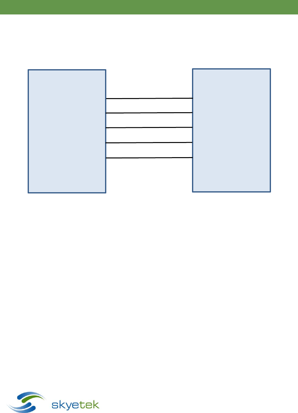
10.3 SPI
The SkyeModule Nova provides a simple four-wire SPI host interface. There is also an optional data ready signal to
indicate that the current command is complete and data is available for the host. Figure 10-4 shows an example of
a host interface connection using SPI. Power and ground lines are omitted from this drawing for simplicity. Please
refer to Figure 10-1 for power and ground connection details.
Figure 10-4: SPI Simplified Connection Diagram
The protocol for requests to the SkyeModule Nova is outlined below:
The data packet exchange between the host (SPI Master) and the Nova (SPI Slave) uses SkyeTek Protocol
v3 (Binary Mode only). See more about the protocol in section 12, Communicating with the Module.
The host must implement SPI master functionality.
The SCK line is the master clock controlled by the host and should remain low during idle state.
The slave select line is active low.
The data is setup on the rising edge of SCK.
The message data is latched on the falling edge of SCK.
The MOSI signal line provides the data from the host to the SkyeModule Nova.
Supports data rates up to 4 MBit
Both 3.3V and 5V logic levels are allowed. See logic levels in section Error! Reference source not found.,
Error! Reference source not found..
The timing diagram in Figure 10-5 illustrates this behavior.
SkyeModule Nova
SSEL (Pin 14)
SCK (Pin 12)
MOSI (PIN 10)
MISO (PIN 8)
GPIO3 (PIN 45)
(Optional Data Ready)
SPI Host
SSEL
SCK
MOSI
MISO
Data Ready
(Optional GPIO Input)
SkyeModule Nova Datasheet - Preliminary Page | 29
Skyetek Inc
1732 Wazee St. Ste 202
Denver, CO 80202
www.skyetek.com
Main 720.328.3425 Fax:720.228.2400
CLK
MOSI
SSEL
Sampling Points
Byte Cycle
10 MHz (max)
Figure 10-5: SPI Request Setup and Sample Timing
For the request data on the MOSI line, the host software should keep the SSEL pin at steady state low as
shown in Figure 10-6 below.
The time delay Td,MAX between byte cycles in a request should not exceed 5 ms. After 5 ms the
SkyeModule Nova will timeout, signifying the end of the request.
CLK
MOSI
SSEL
Td,MAX
Request
Figure 10-6: SPI Request Timing
SkyeModule Nova Datasheet - Preliminary Page | 30
Skyetek Inc
1732 Wazee St. Ste 202
Denver, CO 80202
www.skyetek.com
Main 720.328.3425 Fax:720.228.2400
The protocol for retrieving the response data is outlined below:
The SkyeModule Nova is half duplex so the response data must be retrieved after the request has been
sent.
The GPIO3_DR (data ready) signal will transition high when data is available for the host.
If data ready is not implemented on the host, the host can poll the module starting 1ms after the
command send is complete. The module will respond with 0x00 when no data is present, and 0x02 (start
of frame) when data is available.
Response data will be thrown away if not read within 10 seconds of becoming available.
The MISO signal provides the response data from SkyeModule Nova to the host.
To retrieve data on the MISO line, the SSEL (Slave Select) signal must be low when the clock is sent for an
entire byte. Between bytes, SSEL can either stay low or transition high again as long as it transitions
low before the first clock of the next byte.
The host can use the data length field (response bytes 2 and 3) in order to determine how many
bytes to read from the module as these first bytes will always be present immediately following a
start of frame (0x02).
Figure 10-7 below shows the timing required to retrieve data on the MISO line.
CLK
MISO
SSEL
Response
GPIO3_DR
Figure 10-7: SPI Response Timing
NOTE – Not reading the entire response before sending another command can cause undesired behavior. Always
make sure to read the entire response when using the SPI interface.
SkyeModule Nova Datasheet - Preliminary Page | 31
Skyetek Inc
1732 Wazee St. Ste 202
Denver, CO 80202
www.skyetek.com
Main 720.328.3425 Fax:720.228.2400
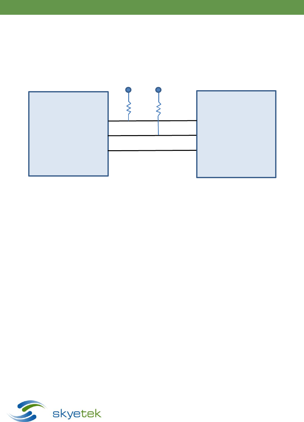
10.4 I2C
The SkyeModule Nova supports can act as an I
2
C slave device. External pull up resistors are required on the SDA
and SCL lines as shown in
Figure 10-8: I2C Connection Diagram. There is also an optional data ready signal to indicate that the current
command is complete and data is available for the host.
Up to +5V
2.2K 2.2K
Figure 10-8: I2C Connection Diagram
The protocol for communicating via I2C is outlined below:
The I2C interface uses a standard two-wire connection in which SCL is the master clock and SDA is a
bidirectional serial data line.
The data packet exchange between the host (I2C Master) and the Nova (I2C Slave) uses SkyeTek Protocol
v3 (Binary Mode only). See more about the protocol in section 12, Communicating with the Module.
I2C fast mode plus (1MHz), I
2
C fast mode (400 kHz), and 100kHz data rates are all supported.
The data is sent and received MSB first.
Up to 5V logic levels are allowed. See logic levels in section Error! Reference source not found., Error!
Reference source not found..
The device uses a 7-bit address
The default address = 0x7F, but the address can be changed with the Reader ID system parameter. See
more about this system parameter in section 13.3.5, Reader ID.
SkyeModule Nova
SDA (Pin 32)
SCL (Pin 30)
GPIO3 (PIN 45)
I2C Master
SDA
SCL
Data Ready (optional)

SkyeModule Nova Datasheet - Preliminary Page | 32
Skyetek Inc
1732 Wazee St. Ste 202
Denver, CO 80202
www.skyetek.com
Main 720.328.3425 Fax:720.228.2400
The communication scheme from host to module is as follows:
Initiate a start condition (SDA transitions low while SCL is high).
Send the nine bits of the initial start packet as follows:
o Send the 7-bit address.
o Send a write bit as the eighth bit (0 for writing from the host to the slave).
o Send the ninth bit as the “acknowledge” bit (ACK)
o If the reader recognizes the address, it pulls SDA low to acknowledge
Use the bus to clock each byte of the SkyeTek protocol request.
After sending the entire request, initiate a stop condition. (SCL transitions high, and then SDA transitions
high while SCL is high)
Wait for command to complete:
The GPIO3_DR (data ready) signal will transition high when data is available for the host to read.
If data ready is not implemented on the host, the host can poll the module after the request is sent. The
module will NAK to a read while it is busy executing a command.
Communication scheme from module to host is as follows:
Initiate a start condition. (SDA transitions low, and then SCL transitions low.)
Send the nine bits of the initial start packet as follows:
o Send the 7-bit address.
o Send a read bit as the eighth bit (1 for reading from the slave to the host).
o Send the ninth bit as the “acknowledge” bit (ACK)
o If the reader recognizes the address, it pulls SDA low to acknowledge
o If the address isn’t recognized or the module is busy the SDA bit will remain high during the ACK
bit.
Clock each byte of the SkyeTek protocol response from the module.
After receiving the response, is received, initiate a stop condition. (SDA transitions high while SCL is high.)
SDA must transition while the clock is low and remain stable while the clock is high.
Response data will be thrown away if not read within 10 seconds of becoming available.
Recommended response handler method #1 (polling):
Read a single byte continuously until the reader ACKs and a 0x02, start of frame is received
Read two bytes which contain the message length
Read the remaining message length
Recommended response handler method #2 (using data ready signal):
Poll on the data ready signal until it transitions high, indicating that data is present
Read three bytes, the last two contain the message length
Read the remaining message length

SkyeModule Nova Datasheet - Preliminary Page | 33
Skyetek Inc
1732 Wazee St. Ste 202
Denver, CO 80202
www.skyetek.com
Main 720.328.3425 Fax:720.228.2400
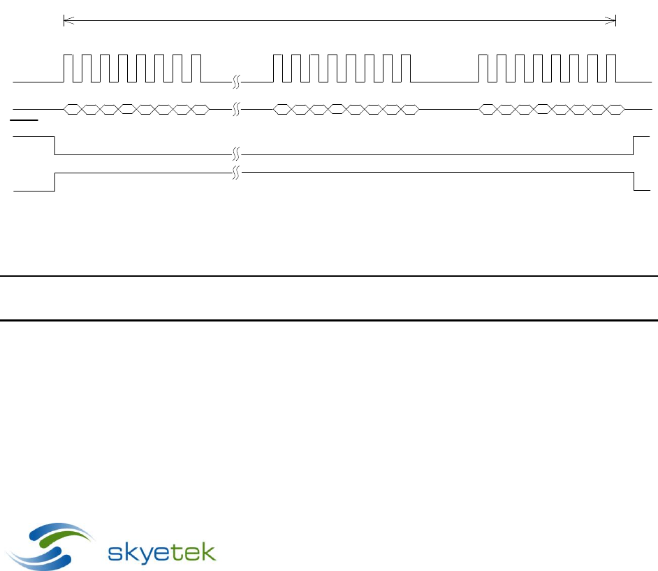
A timing diagram illustrating the I2C data transfer is shown in the figure below:
SCL
SDA
Start
7-bit Address R/W ACK 8-bit Data ACK 8-bit Data ACK/NACK
1 - 7 891 - 8 91 - 8 9
Stop
Figure 10-9: I2C Timing Diagram
NOTE – Not reading the entire response before sending another command can cause undesired behavior. Always
make sure to read the entire response when using the I2C interface.
11 SkyeModule Nova Antenna Options
The SkyeModule Nova has 2 antenna ports to connect external antennas. The ports use an Ultra Miniature
Connector (U.FL) to save space and cost. Any 50 ohm antenna in the appropriate frequency band (865-
868MHz for Europe, 920-928MHz for North America) can be used with the Nova, however to maintain
compliance with FCC/IC regulations, we recommend using those (or similar type) antennas specified in
section 9 of this document in the USA and Canada.
The SkyeModule Nova also uses an advanced Adaptive Antenna Tuning circuit to ensure a quality impedance
match with any antenna. The user can take advantage of this feature by first attaching the antenna to the
port they would like to use, then sending a SkyeTek Protocol command to the Nova for it to execute its tuning
sequence. The Nova will measure the reflected power caused by impedance mismatch and then will
automatically compensate, delivering the maximum power to the antenna while reducing noise in the
system.
NOTE – Read range depends on antenna choice and operating environment. Range can vary widely, depending on
your choice of tag inlay and antenna gain.
SkyeModule Nova Datasheet - Preliminary Page | 34
Skyetek Inc
1732 Wazee St. Ste 202
Denver, CO 80202
www.skyetek.com
Main 720.328.3425 Fax:720.228.2400
12 Communicating with the Module
12.1 Host Communication (SkyeTek Protocol v3)
The SkyeModule Nova operates under control of a host according to SkyeTek Protocol v3. The basic
command and response formats are illustrated for your reference in the following two sections 12.2 and
12.3. The best way to get started creating and understanding commands is to follow the application
notes below while using the Protocol Builder in SkyeWare v4:
Nova Basic Tag Commands
– Guides you through the select tag, read tag and write tag commands.
SkyeTek Protocol v3 Reader Commands
– Explains how to read and write system parameters.
For more feature specific commands, use the tag specific application notes listed in the
Additional
Reading
section 1.3.
For a quick reference on the protocol if you already know the command you want to use, see the
SkyeTek
Protocol v3 Reference Guide
. This provides detailed information on each command structure, error
codes, and tags types. Be warned that this document is very lengthy as it details every command
available for every SkyeTek module.
12.2 Request Formats
Flags
Cmd.
Tag
Type
TID
Len.
TID
Addr.
# of
Blks.
Data
Len.
Data
CRC
4
4
4
4
32
(max)
4
4
4
2K
4
Table 12-1: Request Format (bytes), ASCII Mode
Msg.
Len.
Flags
Cmd.
Tag
Type
TID
Len.
TID
Addr
.
# of
Blks.
Data
Len.
Data
CRC
2
2
2
2
1
32
(max)
2
2
2
1K
2
Table 12-2: Request Format (bytes), Binary Mode
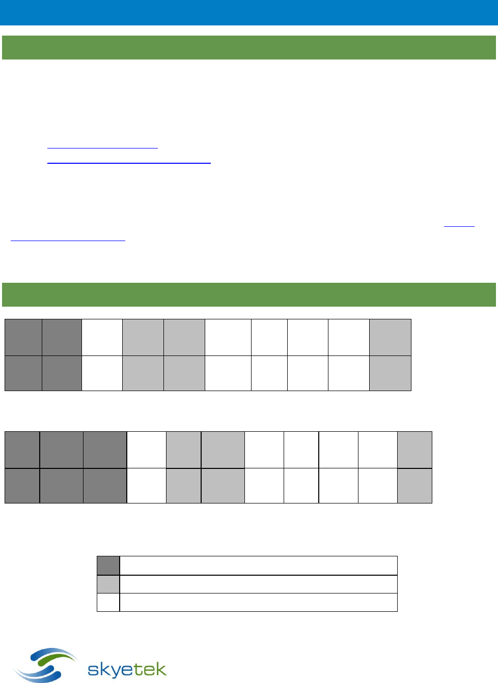
Required Fields (must be present at all times)
Optional fields (depending on the command and flags)
Required fields, depending on the command
SkyeModule Nova Datasheet - Preliminary Page | 35
Skyetek Inc
1732 Wazee St. Ste 202
Denver, CO 80202
www.skyetek.com
Main 720.328.3425 Fax:720.228.2400
12.3 Response Formats
Message
Length
Response Code
Tag Type
Data Length
Response
Data
CRC
2
2
2
2
1K
2
Table 12-3: Response Format (bytes), Binary Mode
Required Fields (must be present at all times)
Optional fields (depending on the command and flags)
Required fields, depending on the command

SkyeModule Nova Datasheet - Preliminary Page | 36
Skyetek Inc
1732 Wazee St. Ste 202
Denver, CO 80202
www.skyetek.com
Main 720.328.3425 Fax:720.228.2400
13 System Parameters
13.1
System Parameter Summary
System parameters let you configure reader settings to customize the reader for your environment. You
can temporarily alter parameters in memory or change the default values that are stored on the
SkyeModule Nova’s non-volatile memory. The following table summarizes the parameters. (
See System
Parameter Detail in section 13.3 for detailed information about each parameter
)
Parameter Name
Address
(hex)
Num.
Blocks
(hex)
Read/
Write
Default Value
Serial Number
0x0000
0x0004
R
0x00000000
Firmware Version
0x0001
0x0004
R
0xXXXXXXXX (depending on release)
Hardware Version
0x0002
0x0004
R
0xXXXXXXXX (depending on release)
Product Code
0x0003
0x0002
R
0x0010
Reader ID
0x0004
0x0004
R/W
0xFFFFFFFF
Reader Name
0x0005
0x0032
R/W
SkyeModule Nova (in ASCII Format)
Host Interface Type
0x0006
0x0001
R/W
0x01 (TTL)
Interface Baud Rate
0x0007
0x0001
R/W
0x02 (38400)
User Port Direction
0x0008
0x0001
R/W
0x00
User Port Value
0x0009
0x0001
R/W
0x0F
MUX Control
0x000A
0x0001
R/W
0x00
Operating Mode
0x000C
0x0001
W
N/A
Tag Command Retries
0x0011
0x0001
R/W
0x03
Power Level
0x0012
0x0001
R/W
0xDC (27 dBm)
Current Frequency
0x0004
0x0004
R/W
0x3689CAC0 (915 MHz)
Start Frequency
0x0031
0x0004
R/W
0x35C80160 (902.3 MHz)
Stop Frequency
0x0032
0x0004
R/W
0x374B9420 (927.7 MHz)
Hop Channel Spacing
0x0034
0x0004
R/W
0x00030D40 (200 KHz)
Frequency Hopping Sequence
0x0035
0x0001
R/W
0x01 (pseudo-random)
Modulation Depth
0x0036
0x0001
R/W
0x64 (100%)
Regulatory Mode
0x0037
0x0001
R/W
0x00
Table 13-1: SkyeModule Nova System Parameters

SkyeModule Nova Datasheet - Preliminary Page | 37
Skyetek Inc
1732 Wazee St. Ste 202
Denver, CO 80202
www.skyetek.com
Main 720.328.3425 Fax:720.228.2400
13.2 Changing System Parameters
CAUTION – Changing system parameter values – especially the default values – can render your
SkyeModule Nova non-operational in your environment. Research, record, and test all planned
changes to make sure they are compatible with your system.
You can read or write system parameters via the following commands:
Read System Parameter – Reads the current value of the system parameter at the memory address
specified.
Write System Parameter – Writes a new value to the system parameter at the memory address specified.
Store Default System Parameter – Writes a new system parameter value to the non-volatile memory. This
saves the setting even after a power cycle or reset.
Retrieve Default System Parameter – Reads the system parameter value at the address specified out of
non-volatile memory.
See System Parameter Detail in section 13.3 for detailed information about individual parameters.
For full examples of how to use these commands, see the system parameter examples found in the Using
SkyeProtocol V3 Reader Commands application note.
CAUTION – Resetting (cycling power) on your SkyeModule Nova causes all system parameters to
revert to their default values. Any changes made to system parameters in memory are lost at reset
unless you write them to the non-volatile memory as the new default values. Any changes to the
default values do not take effect until the reader is reset.
13.3 System Parameter Details
This section describes the SkyeModule Nova system parameters.
13.3.1 Serial Number
Returns the serial number of the reader
Parameter address: 0x0000
Length (bytes): 4
Default value: 0x00000000
Read-only
13.3.2 Firmware Version
Returns the firmware version currently loaded on the reader. (Refer to the
SkyeModule Nova
Release Notes
for more information about the specific firmware release.)
Refer to the
SkyeWare User Guide
for information about updating firmware.

SkyeModule Nova Datasheet - Preliminary Page | 38
Skyetek Inc
1732 Wazee St. Ste 202
Denver, CO 80202
www.skyetek.com
Main 720.328.3425 Fax:720.228.2400
Parameter address: 0x0001
Length (bytes): 4
Default value: 0xXXXXXXXX (depending on release)
The firmware version uses this format:
o
Major revision (1 Byte)
o
Minor revision (1 Byte)
o
Current build number (2 bytes)
Read-only
13.3.3 Hardware Version
Returns the current hardware version of the reader
Parameter address: 0x0002
Length (bytes): 4
Default value: 0xXXXXXXXX (depending on release)
The hardware version uses the following format:
o Major revision (1 Byte)
o Minor revision (1 Byte)
o Current build number (2 bytes)
Read-only
13.3.4 Product Code
Returns the SkyeTek product code identifier. (Each SkyeTek Product has a unique product code.)
Parameter address: 0x0003
Length (bytes): 2
Default value: 0x0010
Read-only
13.3.5 Reader ID
This was used for a deprecated SkyeTek protocol feature. It is now used as the I2C address of the reader
in I2C mode. The least significant 7 bits of the reader ID act as the 7-bit I2C address.
Example: A value of 0x0000001B would indicate an I2C address of 0x1B
Parameter address: 0x0004
Length (bytes): 4
Default value: 0xFFFFFFFF
Read/write
13.3.6 Reader Name
Identifies a reader with a 32-byte user-defined name.

SkyeModule Nova Datasheet - Preliminary Page | 39
Skyetek Inc
1732 Wazee St. Ste 202
Denver, CO 80202
www.skyetek.com
Main 720.328.3425 Fax:720.228.2400
Parameter address: 0x0005
Length (bytes): 32 (20 hex)
Default value is “SkyeModule Nova” (in hex)
Read/write
13.3.7 Host Interface Type
Identifier for the type of host interface being used.
Parameter address: 0x0006
Length (bytes): 1
Default value: 0x01 (TTL Serial)
Valid host interface values are:
o
0x01 – TTL Serial
o
0x03 – SPI
o
0x05 – I
2
C
o
0x06 – USB
o
Any other values are invalid and are ignored.
Read/write
13.3.8 Interface Baud Rate
Sets the baud rate of the host interface.
Works for the TTL Serial host interface only.
Parameter address: 0x0007
Length (bytes): 1
Default value: 0x02 (38,400)
Valid baud rate values are:
o
0x01 – 19200
o
0x02 – 38400
o
0x03 – 57600
o
0x04 – 115200
o
0x05 – 1 MBaud
o
Any other value – 9600
Read/write
13.3.9 User Port Direction
Sets the direction of the GPIO pins of the reader.
Parameter address: 0x0008
Length (bytes): 1
Default value: 0x00
Default value is 0x00 (GPIO pins are outputs).
A one in the bit position indicates that the corresponding GPIO pin is an input.

SkyeModule Nova Datasheet - Preliminary Page | 40
Skyetek Inc
1732 Wazee St. Ste 202
Denver, CO 80202
www.skyetek.com
Main 720.328.3425 Fax:720.228.2400
A zero in the bit position indicates that the corresponding GPIO pin is an output.
Bits correspond to the pins as follows:
o BIT0 – GPIO 0
o BIT1 – GPIO 1
o BIT2 – GPIO 2
o BIT3 – GPIO 3
o BIT4 - BIT7 – Reserved
Read/write
13.3.10 User Port Value
Sets or reads the value of the GPIO pins of the reader.
Parameter address: 0x0009
Length (bytes): 1
Default value is 0x0F (GPIO pins are logic high).
A one in the bit position indicates that the corresponding GPIO pin is logic high.
A zero in the bit position indicates that the corresponding GPIO pin is logic low.
Bits correspond to the pins as follows:
o BIT0 – GPIO 0
o BIT1 – GPIO 1
o BIT2 – GPIO 2
o BIT3 – GPIO 3
o BIT4 - BIT7 – Reserved
Read/write
13.3.11 Operating Mode
Can put the reader into sleep mode or into keyboard wedge mode.
Parameter address: 0x000C
Length (bytes): 1
Default value is 0x00 (active).
Writing a value 0x01 to this system parameter puts the reader in sleep mode.
Sending a single byte on the interface that put the reader to sleep wakes the reader from sleep mode.
NOTE: SOFTWARE SLEEP MODE DOES NOT FUNCTION IN USB COMMUNICATIONS. This is planned for
future firmware releases.
Write Only
13.3.12 Tag Command Retries
Sets the number of times a tag command will be retried internally.
Parameter address: 0x0011
Length (bytes): 1
Default value is 0x03

SkyeModule Nova Datasheet - Preliminary Page | 41
Skyetek Inc
1732 Wazee St. Ste 202
Denver, CO 80202
www.skyetek.com
Main 720.328.3425 Fax:720.228.2400
In very time dependent applications, it is recommended to set this parameter to 0 as this removes much
of the variability of response time.
In most situations, a retry number of 3 is sufficient.
Read/write
WARNING: Setting this parameter too high can cause very long response times when there is no tag or a
failing tag in the field.
13.3.13 Power Level
Configures the power level for the reader.
Parameter address: 0x0012
Length (bytes): 1
Default value: 0xDC (27 dBm)
RF output Power level may be set in steps of 0.1 dB from 10 dBm to 27 dBm.
Power levels are written in hex corresponding to a decimal value between 50 and 220 (see Table 14-10).
Use the following equation to calculate the value to be written for a desired power level:
(Desired power in dBm – 5)/0.1 = decimal value to write to system parameter
Table 13-2: Common Power Values
Power (dBm)
SkyeTek Decimal Value
Hex Equivalent
10
50
0x32
12
70
0x46
15
100
0x64
17
120
0x78
20
150
0x96
21
160
0xA0
24
190
0xBE
27
220
0xDC
Read/write
NOTE – SkyeModule Nova’s shipped with the SkyeTek Development Kit are preset to a power level of 27 dBm.

SkyeModule Nova Datasheet - Preliminary Page | 42
Skyetek Inc
1732 Wazee St. Ste 202
Denver, CO 80202
www.skyetek.com
Main 720.328.3425 Fax:720.228.2400
NOTE – Setting the regulatory mode in section XXX below, will automatically set all RF parameters including the
frequency start and stop, hop spacing, modulation depth etc. It is strongly recommended that (only) this
parameter be set to maintain compliance with applicable rules for the regulatory region selected, under normal
operation.
13.3.14 Current Frequency
Sets the current frequency with which the reader singulates a tag.
Parameter address: 0x0030
Length (bytes): 4
Default value: 0x3689CAC0 (915 MHz)
This parameter is a 4-byte hex equivalent of the frequency. Table 14-11 shows hex values for commonly
used frequencies.
Read/write
13.3.15 Start Frequency
Sets the low end of the frequency range under which the reader operates.
Parameter address: 0x0031
Length (bytes): 4
Default value: 0x35C80160 (902.3 MHz)
This parameter is written with a 4-byte hex equivalent of the frequency desired. See Table 14-11 for
commonly used frequencies and their hex values.
To enable frequency hopping, set a frequency range using the Start Frequency and Stop Frequency system
parameters. Then use the Frequency Hopping Sequence parameter to set the frequency hopping mode
(either sequential or pseudo-random). To disable frequency hopping, set the Start Frequency and Stop
Frequency parameter to the same value.
Read/write
13.3.16 Stop Frequency
Sets the high end of the frequency range under which the reader operates.
The parameter address: 0x0032
Length (bytes): 4
Default value: 0x374B9420 (927.7 MHz)
This parameter is written with a 4-byte hex equivalent of the frequency desired. See table 14-11 for
commonly used frequencies and their hex values.
To enable frequency hopping, set a frequency range using the Start Frequency and Stop Frequency system
parameters. Then use the Frequency Hopping Sequence parameter to set the frequency hopping mode
(either sequential or pseudo-random). To disable frequency hopping, set the Start Frequency and Stop
Frequency parameter to the same value.
Read/write

SkyeModule Nova Datasheet - Preliminary Page | 43
Skyetek Inc
1732 Wazee St. Ste 202
Denver, CO 80202
www.skyetek.com
Main 720.328.3425 Fax:720.228.2400
Table 13-3: Commonly Used Frequencies
Frequency (MHz)
Hex Equivalent
Description
865.7
0x339988A0
EU Start
866.7
0x33A8CAE0
EU Center
867.9
0x33BB1A60
EU Stop
902.5
0x35C80160
NA Start
915.0
0x3689CAC0
NA Center
927.5
0x374B9420
NA Stop
13.3.17 Hop Channel Spacing
Controls the hop channel spacing when frequency hopping is enabled.
Parameter address: 0x0034
Length (bytes): 4
Default value: 0x00030D40 (200 KHz)
To enable frequency hopping, set a frequency range using the Start Frequency and Stop Frequency system
parameters. Then use the Frequency Hopping Sequence parameter to set the frequency hopping mode
(either sequential or pseudo-random). To disable frequency hopping, set the Start Frequency and Stop
Frequency parameter to the same value.
Read/write
13.3.18 Frequency Hopping Sequence
Switches the hopping sequence between pseudo-random and sequential mode.
Parameter address: 0x0035
Length (bytes): 1
Default value: 0x01 (pseudo-random)
To set the reader to sequential hopping mode, write 0x00 to this parameter.
To reset the reader to pseudo-random hopping sequence, write 0x01 to this parameter.
To enable frequency hopping, set a frequency range using the Start Frequency and Stop Frequency system
parameters. Then use the Frequency Hopping Sequence parameter to set the frequency hopping mode
(either sequential or pseudo-random). To disable frequency hopping, set the Start Frequency and Stop
Frequency parameter to the same value.
Read/write
13.3.19 Modulation Depth
Sets the modulation depth of the reader-to-tag transmissions, as calculated by the equation: (Vmax –
Vmin)/Vmax
Parameter address: 0x0036

SkyeModule Nova Datasheet - Preliminary Page | 44
Skyetek Inc
1732 Wazee St. Ste 202
Denver, CO 80202
www.skyetek.com
Main 720.328.3425 Fax:720.228.2400
Length (bytes): 1
Default value: 100%
The values for the modulation depths are in steps of 10, ranging from 10% to 100%.
The values are the hex equivalent of the corresponding modulation depth.
Table 13-4: Common Modulation Depth Values
Modulation Depth (%)
Hex Equivalent
30
0x1E
80
0x50
90
0x5A
100
0x64
The modulation depth is calculated by the reader using the equation:
(VMAX – VMIN)/VMAX where VMAX is the RF voltage when transmit power is maximum and VMIN is the RF
voltage when the transmit power is minimum. (For 100% modulation depth, VMIN equals zero.)
See the manufacturer’s tag data sheet for the modulation depth supported for the tags in your
application.
Read/write
13.3.20 Regulatory Mode
Enables pulse shaping, listen before talk, and timing modifications for regions with special regulatory
requirements, such as Europe.
Parameter address: 0x0037
Length (bytes): 1
Default value 0x00 (no pulse shaping)
Read/write
Table 13-5: Regulatory Mode Values
Mode
Hex Value
No pulse shaping—Australia/New Zealand, Hong Kong, North America, Singapore,
Taiwan
0x00
ETSI/Europe
0x01
Not used
0x02
Not used
0x03
Korea
0x04

SkyeModule Nova Datasheet - Preliminary Page | 45
Skyetek Inc
1732 Wazee St. Ste 202
Denver, CO 80202
www.skyetek.com
Main 720.328.3425 Fax:720.228.2400

SkyeModule Nova Datasheet - Preliminary Page | 46
Skyetek Inc
1732 Wazee St. Ste 202
Denver, CO 80202
www.skyetek.com
Main 720.328.3425 Fax:720.228.2400
14
Special Features
14.1 Sleep Modes
The Nova has two low power sleep modes: deep sleep (hardware controlled) and software sleep mode. The deep
sleep mode has the lowest power consumption but a longer wake time. It can only be set using the N_DEEP_SLEEP
pin 20 of the host interface connector. There is an internal pull-up on this pin, so if it is unused it can be left
floating. To put the reader into deep sleep, set this pin low. Software sleep mode can be set using the Operating
Mode system parameter. See the System Parameters section 13 for details. Current consumption and wake times
for both modes can be found in the Error! Reference source not found. section Error! Reference source not
found. and Error! Reference source not found. section Error! Reference source not found., respectively.
NOTE: SOFTWARE SLEEP MODE DOES NOT WORK IN USB COMMUNICATIONS. This is planned for future
firmware releases.
14.2 Feature Requests
Request a feature for the Nova module on the SkyeTek support page at support.skyetek.com!