JCM Technologies RB-G-RX10 Transceiver for Automatic Door Safety Edges Relay Output User Manual
JCM Technologies, S.A. Transceiver for Automatic Door Safety Edges Relay Output
UserManual.wiki
>
JCM Technologies
>
RB G RX10 User Manual
User Manual
Navigation menu
Upload a User Manual
Namespaces
Wiki Guide
HTML
PDF
Info
Views
User Manual
Discussion / Help
Navigation
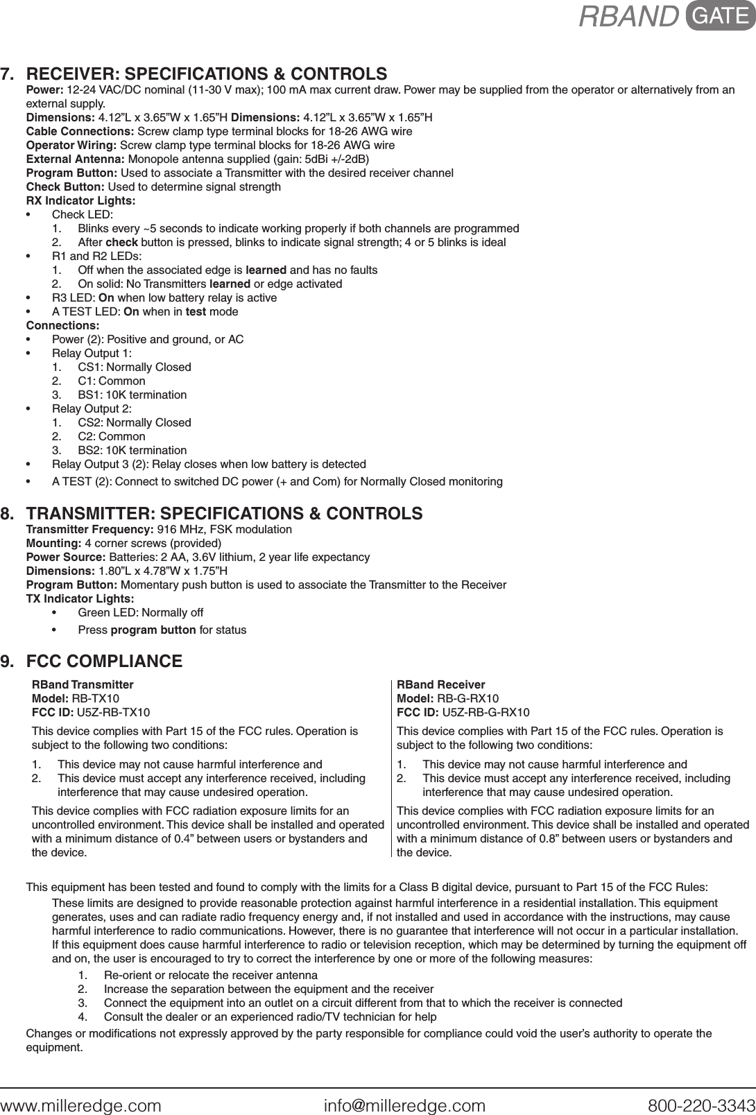
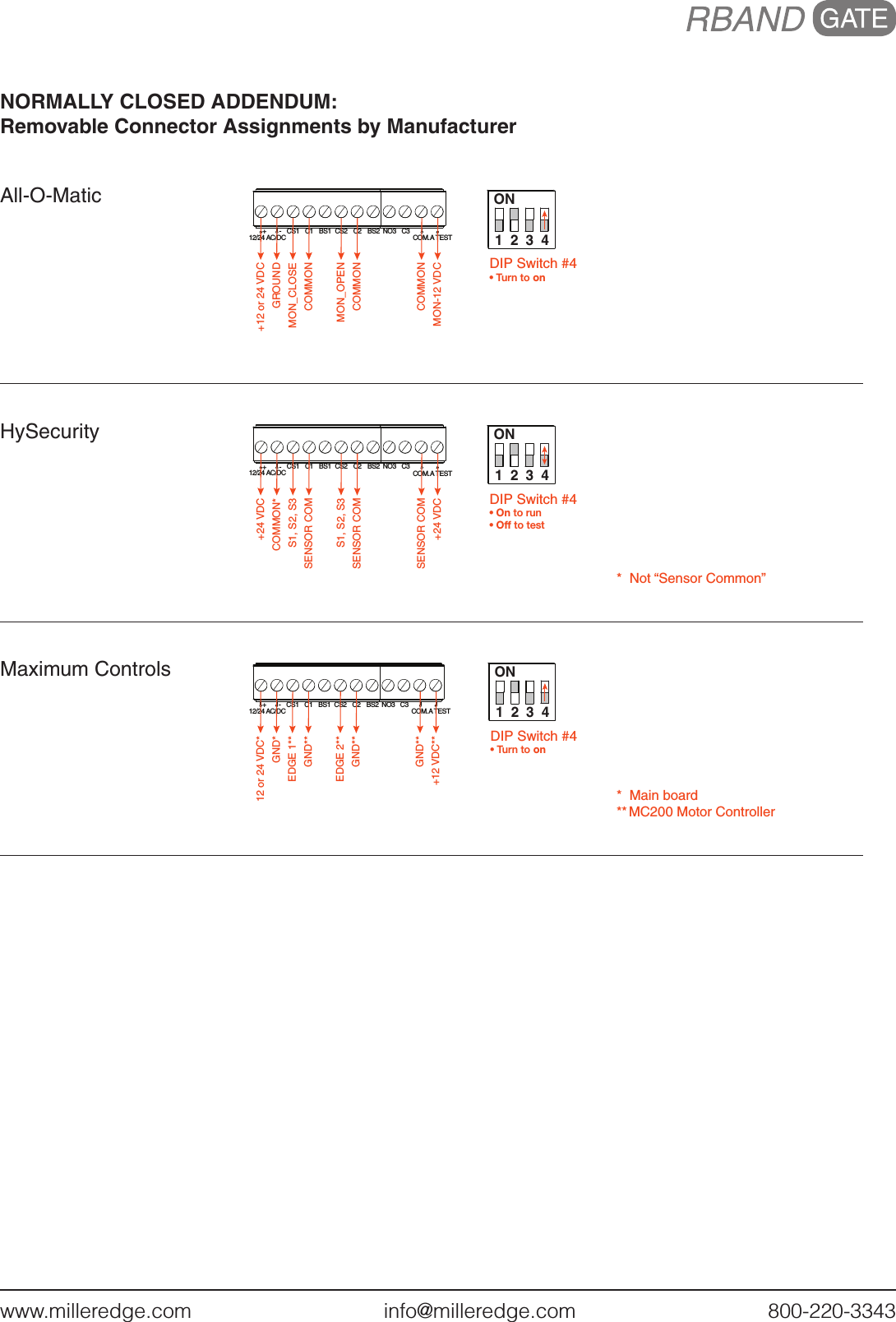
![www.milleredge.com info@milleredge.com 800-220-3343INSTALLATION INSTRUCTIONSModel: RB-G-K10 IMPORTANT: THIS DEVICE MUST BE PROFESSIONALLY INSTALLED. READ AND UNDERSTAND ALL INSTRUCTIONS BEFORE BEGINNING INSTALLATION.The Miller Edge RBand Monitored Gate Edge Transmitter/Receiver system is intended to provide a wireless connection between a monitored sensing edge and a motorized operator that controls the associated gate. RBand meets the 2016 UL 325 requirements for monitored devices and has been certified as a UL 325 Recognized Component. It is designed for use with operators that comply with 2016 UL 325 using a Miller Edge 10K Sensing Edge.1. PARTS LISTKit Contents:1. RBand Edge Transmitter (RB-TX10)2. RBand Gate Edge Receiver (RB-G-RX10)3. Receiver antenna4. (2) 3.6V AA lithium batteries*5. (4) #6 pan head transmitter mounting screws*Replacement 3.6V AA lithium batteries can be purchased at your local electronics store or via Miller Edge.Required:• 1/8” flat blade screwdriver• 1/4” flat blade screwdriver• Miller Edge 10K (T2/blue band) Sensing Edge • Coaxial cable for exterior mounted antenna • Coaxial bulkhead adapter, female/femaleRecommended:• Multi-meter capable of reading 10KΩ• Mounting screws for the Receiver2. RECEIVER: INSTALLATION2-1. Remove operator cover and turn off the power to the gate operator.2-2. Determine where to place the external mounted antenna so it is in line of sight with the Transmitter for the entire range of travel [IMAGE 1]. Prepare the antenna coax as necessary. 2-3. Remove Receiver cover and mount the base inside the operator, positioning it for optimum ease of wiring. 2-4. Connect power to the terminals marked 12/24 AC/DC (polarity sensitive) on the removable 8-pin connector [IMAGE 2]. 2-5. Determine which monitored interface your operator uses. Connect the COM (C1/C2) and the correct output connections (N.C. = CS1/CS2 or 10K = BS1/BS2) to your operator. There are 2 separate relays (channels): R1 and R2. The A Test terminals must be used for operators requiring N.C. inputs. Enable with DIP switch 4 [TABLE 1].2-6. Replace the Receiver cover and turn on power to the operator. Note: it takes ~5 seconds for the Receiver to initialize. Note: RBand 10K Gate Edge Receiver is compatible with up to 3 RBand Transmitters on 2 channels (6 total).RB-G-K10_Install_A4_20170706IMAGE 1. RBand Transmitter Installation with Gate EdgeRBAND RECEIVER MOUNTED INSIDE OPERATOR WITH EXTERNAL ANTENNAOPERATORANTENNAWIRINGRBAND TRANSMITTER MOUNTED NEAR SENSING EDGESENSING EDGE](https://usermanual.wiki/JCM-Technologies/RB-G-RX10/User-Guide-3462760-Page-1.png)
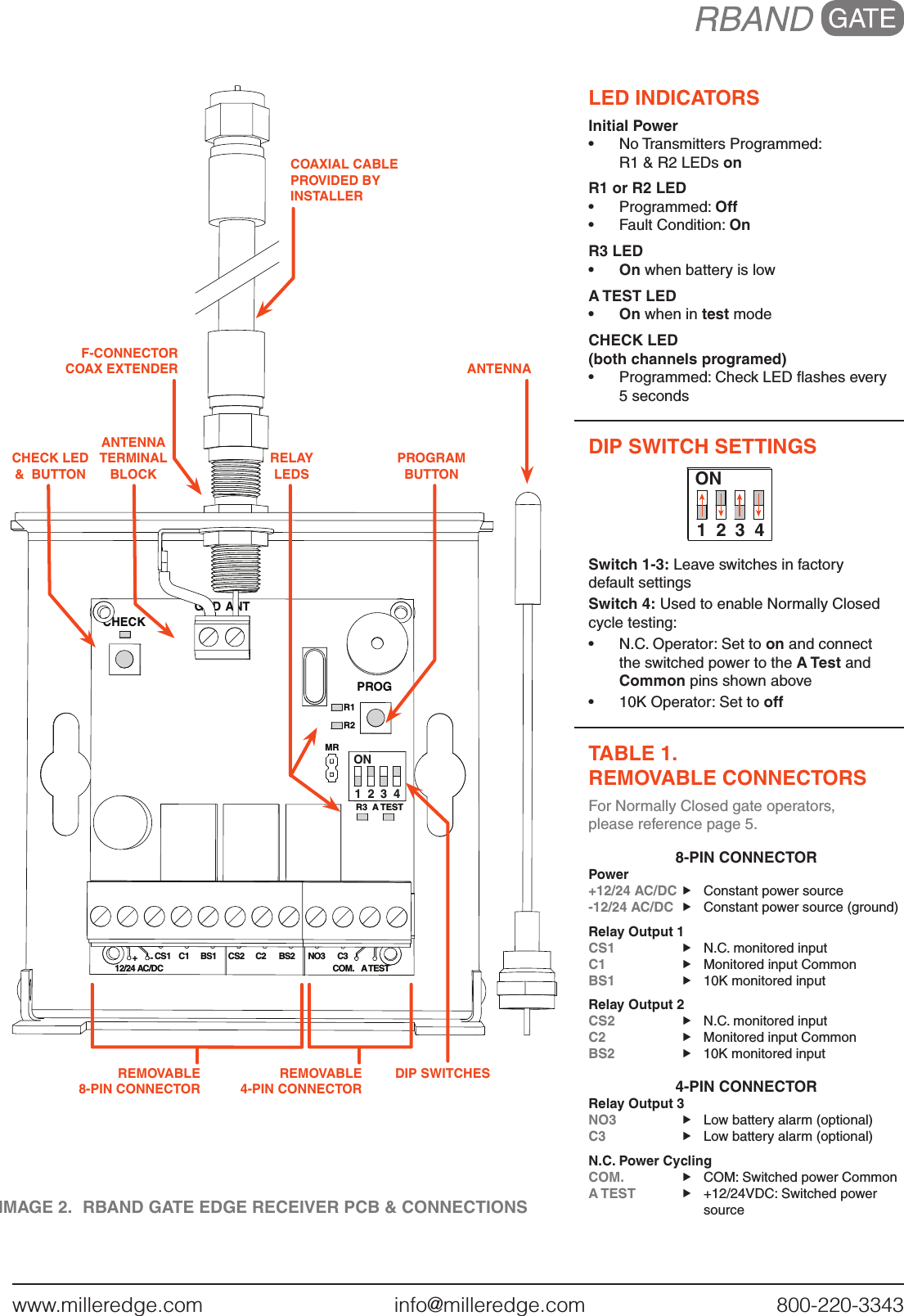
![www.milleredge.com info@milleredge.com 800-220-3343IMAGE 3. RBand Edge Transmitter PCB & Connections3. TRANSMITTER: PROGRAM MODE 3-1. Confirm the Receiver is powered up. Prior to mounting the Transmitter, remove the cover and insert the batteries, noting their polarity. The green LED on the Transmitter should blink to indicate that it has not been associated with the Receiver yet [IMAGE 3].3-2. To enter learn mode, press and hold the Receiver program button for ~2 seconds until the R1 LED turns on, then release the button [IMAGE 2].3-3. Press the Transmitter program button for ~2 seconds [IMAGE 3]. The Receiver should beep. Wait 10 seconds for an additional beep to indicate that programming is complete.3-4. To program a Transmitter to Channel 2, press and hold the Receiver program button until the second beep, then release the button. The R2 LED should be on [IMAGE 2]. Repeat 3-3.4. TRANSMITTER: INSTALL & TEST4-1. Strip back approximately 2 inches of outer covering of sensing edge cable, then feed through Transmitter strain relief fitting. Connect the two sensing edge wires to the removable terminal. Dress the wires with a small service loop and tighten the strain relief. Mount unit utilizing the mounting holes at the 4 corners of the Transmitter box. Affix lid to Transmitter, noting the alignment pin [IMAGE 3].4-2. Test the sensing edge for functionality.5. TROUBLESHOOTINGIf the Receiver does not react to the Transmitter, you can check the RF signal strength:5-1. Press the check button on the Receiver for ~2 seconds [IMAGE 2]; 4 beeps will be heard. You then will hear a beep every 1-1/2 seconds during the check process. Wait about 30 seconds; if no other beeps occur, your system is functioning. 3 quick beeps indicates a communication error. 5-2. Activate the sensing edge and observe the check LED; 3-5 flashes is ideal. Less than 3 flashes means there is a weak signal.5-3. To exit check function, press the check button, or system will time-out after 5 minutes. There will be a series of beeps heard upon exiting.6. ERASING THE RECEIVERIf you need to replace a Transmitter or you have any other programming issues, you may need to erase the Receiver.6-1. To erase any Transmitters programmed into the Receiver, use a screwdriver to short the two pins marked MR next to the DIP switches [IMAGE 2]. 6-2. While shorting the pins, press and hold the program button for several seconds; you will hear a series of 10 beeps followed by a rapid chirping sound. 6-3. When the chirping stops, release the program button. Wait ~10 seconds and you will hear 2 beeps. The Receiver is now ready to be reprogrammed. PROGRAM BUTTONREMOVABLESENSING EDGE TERMINAL BLOCK(4) CORNER MOUNTING HOLESGREEN LEDALIGNMENT PINSTRAIN RELIEF FITTINGALIGNMENT PIN(2) 3.6V AA LITHIUM BATTERIES](https://usermanual.wiki/JCM-Technologies/RB-G-RX10/User-Guide-3462760-Page-3.png)