JCM Technologies RB-G-RX10 Transceiver for Automatic Door Safety Edges Relay Output User Manual
JCM Technologies, S.A. Transceiver for Automatic Door Safety Edges Relay Output
User Manual
www.milleredge.com info@milleredge.com 800-220-3343
INSTALLATION INSTRUCTIONS
Model: RB-G-K10
IMPORTANT: THIS DEVICE MUST BE PROFESSIONALLY INSTALLED.
READ AND UNDERSTAND ALL INSTRUCTIONS BEFORE BEGINNING INSTALLATION.
The Miller Edge RBand Monitored Gate Edge Transmitter/Receiver system is intended to provide a wireless
connection between a monitored sensing edge and a motorized operator that controls the associated gate. RBand
meets the 2016 UL 325 requirements for monitored devices and has been certified as a UL 325 Recognized
Component. It is designed for use with operators that comply with 2016 UL 325 using a Miller Edge 10K Sensing
Edge.
1. PARTS LIST
Kit Contents:
1. RBand Edge Transmitter (RB-TX10)
2. RBand Gate Edge Receiver (RB-G-RX10)
3. Receiver antenna
4. (2) 3.6V AA lithium batteries*
5. (4) #6 pan head transmitter mounting screws
*Replacement 3.6V AA lithium batteries can be
purchased at your local electronics store or via
Miller Edge.
Required:
• 1/8” flat blade screwdriver
• 1/4” flat blade screwdriver
• Miller Edge 10K (T2/blue band) Sensing Edge
• Coaxial cable for exterior mounted antenna
• Coaxial bulkhead adapter, female/female
Recommended:
• Multi-meter capable of reading 10KΩ
• Mounting screws for the Receiver
2. RECEIVER: INSTALLATION
2-1. Remove operator cover and turn off the power to the gate operator.
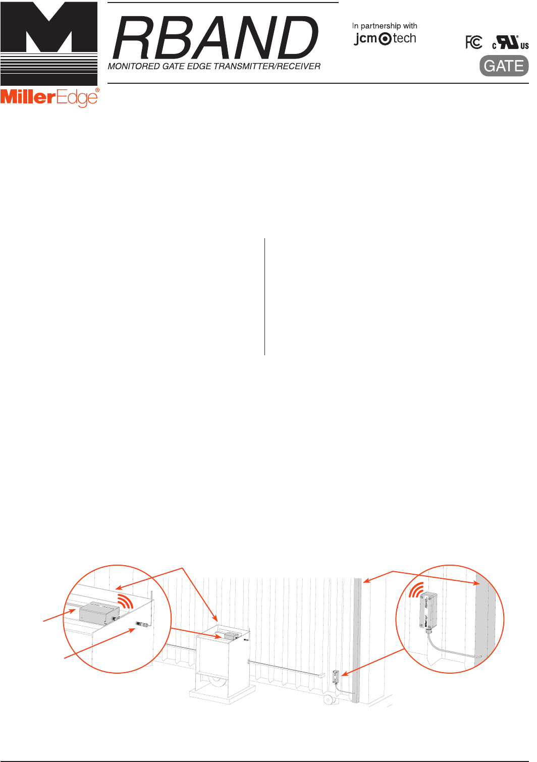
2-2. Determine where to place the external mounted antenna so it is in line of sight with the Transmitter for the
entire range of travel [IMAGE 1]. Prepare the antenna coax as necessary.
2-3. Remove Receiver cover and mount the base inside the operator, positioning it for optimum ease of wiring.
2-4. Connect power to the terminals marked 12/24 AC/DC (polarity sensitive) on the removable 8-pin
connector [IMAGE 2].
2-5. Determine which monitored interface your operator uses. Connect the COM (C1/C2) and the correct output
connections (N.C. = CS1/CS2 or 10K = BS1/BS2) to your operator. There are 2 separate relays (channels):
R1 and R2. The A Test terminals must be used for operators requiring N.C. inputs. Enable with DIP switch 4
[TABLE 1].
2-6. Replace the Receiver cover and turn on power to the operator. Note: it takes ~5 seconds for the Receiver to
initialize.
Note: RBand 10K Gate Edge Receiver is compatible with up to 3 RBand Transmitters on 2 channels (6 total).
RB-G-K10_Install_A4_20170706
IMAGE 1. RBand Transmitter Installation with Gate Edge
RBAND RECEIVER
MOUNTED INSIDE OPERATOR
WITH EXTERNAL ANTENNA
OPERATOR
ANTENNA
WIRING
RBAND TRANSMITTER
MOUNTED NEAR
SENSING EDGE
SENSING EDGE
www.milleredge.com info@milleredge.com 800-220-3343
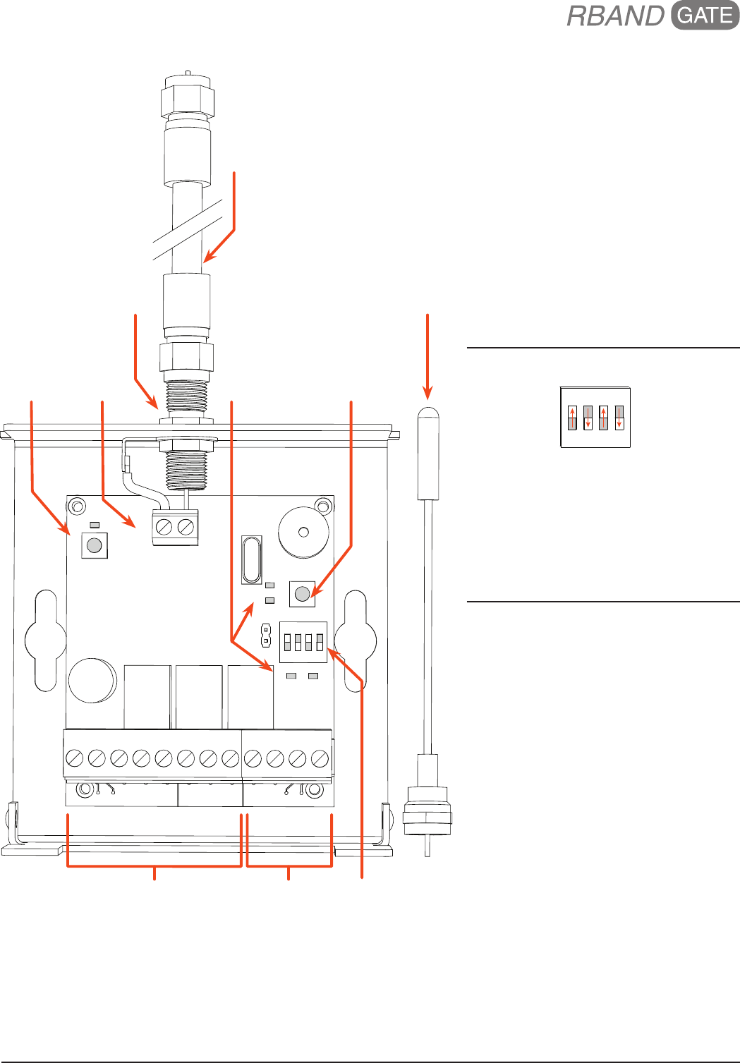
IMAGE 2. RBAND GATE EDGE RECEIVER PCB & CONNECTIONS
LED INDICATORS
Initial Power
• No Transmitters Programmed:
R1 & R2 LEDs on
R1 or R2 LED
• Programmed: Off
• Fault Condition: On
R3 LED
• On when battery is low
A TEST LED
• On when in test mode
CHECK LED
(both channels programed)
• Programmed: Check LED flashes every
5 seconds
DIP SWITCH SETTINGS
ON
1 2 3 4
Switch 1-3: Leave switches in factory
default settings
Switch 4: Used to enable Normally Closed
cycle testing:
• N.C. Operator: Set to on and connect
the switched power to the A Test and
Common pins shown above
• 10K Operator: Set to off
TABLE 1.
REMOVABLE CONNECTORS
For Normally Closed gate operators,
please reference page 5.
8-PIN CONNECTOR
Power
+12/24 AC/DC Constant power source
-12/24 AC/DC Constant power source (ground)
Relay Output 1
CS1 N.C. monitored input
C1 Monitored input Common
BS1 10K monitored input
Relay Output 2
CS2 N.C. monitored input
C2 Monitored input Common
BS2 10K monitored input
4-PIN CONNECTOR
Relay Output 3
NO3 Low battery alarm (optional)
C3 Low battery alarm (optional)
N.C. Power Cycling
COM. COM: Switched power Common
A TEST +12/24VDC: Switched power
source
GND ANT
R2
R1
R3 A TEST
CHECK
PROG
ON
1234
12/24 AC/DC
CS1 C1
+ - BS1 CS2 C2 BS2 NO3 C3
COM. A TEST
MR
PROGRAM
BUTTON
CHECK LED
& BUTTON
REMOVABLE
8-PIN CONNECTOR
DIP SWITCHES
RELAY
LEDS
ANTENNA
TERMINAL
BLOCK
REMOVABLE
4-PIN CONNECTOR
COAXIAL CABLE
PROVIDED BY
INSTALLER
ANTENNA
F-CONNECTOR
COAX EXTENDER
www.milleredge.com info@milleredge.com 800-220-3343
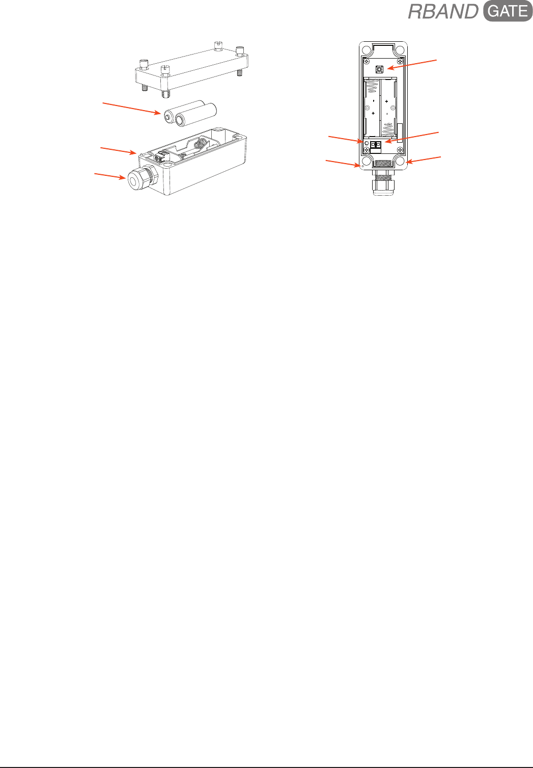
IMAGE 3. RBand Edge Transmitter PCB & Connections
3. TRANSMITTER: PROGRAM MODE
3-1. Confirm the Receiver is powered up. Prior to mounting the Transmitter, remove the cover and insert the
batteries, noting their polarity. The green LED on the Transmitter should blink to indicate that it has not been
associated with the Receiver yet [IMAGE 3].
3-2. To enter learn mode, press and hold the Receiver program button for ~2 seconds until the R1 LED turns
on, then release the button [IMAGE 2].
3-3. Press the Transmitter program button for ~2 seconds [IMAGE 3]. The Receiver should beep. Wait 10
seconds for an additional beep to indicate that programming is complete.
3-4. To program a Transmitter to Channel 2, press and hold the Receiver program button until the second beep,
then release the button. The R2 LED should be on [IMAGE 2]. Repeat 3-3.
4. TRANSMITTER: INSTALL & TEST
4-1. Strip back approximately 2 inches of outer covering of sensing edge cable, then feed through Transmitter
strain relief fitting. Connect the two sensing edge wires to the removable terminal. Dress the wires with a
small service loop and tighten the strain relief. Mount unit utilizing the mounting holes at the 4 corners of the
Transmitter box. Affix lid to Transmitter, noting the alignment pin [IMAGE 3].
4-2. Test the sensing edge for functionality.
5. TROUBLESHOOTING
If the Receiver does not react to the Transmitter, you can check the RF signal strength:
5-1. Press the check button on the Receiver for ~2 seconds [IMAGE 2]; 4 beeps will be heard. You then will hear
a beep every 1-1/2 seconds during the check process. Wait about 30 seconds; if no other beeps occur, your
system is functioning. 3 quick beeps indicates a communication error.
5-2. Activate the sensing edge and observe the check LED; 3-5 flashes is ideal. Less than 3 flashes means
there is a weak signal.
5-3. To exit check function, press the check button, or system will time-out after 5 minutes. There will be a
series of beeps heard upon exiting.
6. ERASING THE RECEIVER
If you need to replace a Transmitter or you have any other programming issues, you may need to erase the
Receiver.
6-1. To erase any Transmitters programmed into the Receiver, use a screwdriver to short the two pins marked
MR next to the DIP switches [IMAGE 2].
6-2. While shorting the pins, press and hold the program button for several seconds; you will hear a series of 10
beeps followed by a rapid chirping sound.
6-3. When the chirping stops, release the program button. Wait ~10 seconds and you will hear 2 beeps. The
Receiver is now ready to be reprogrammed.
PROGRAM BUTTON
REMOVABLE
SENSING EDGE
TERMINAL BLOCK
(4) CORNER
MOUNTING HOLES
GREEN LED
ALIGNMENT PIN
STRAIN RELIEF FITTING
ALIGNMENT PIN
(2) 3.6V AA LITHIUM
BATTERIES

www.milleredge.com info@milleredge.com 800-220-3343
7. RECEIVER: SPECIFICATIONS & CONTROLS
Power: 12-24 VAC/DC nominal (11-30 V max); 100 mA max current draw. Power may be supplied from the operator or alternatively from an
external supply.
Dimensions: 4.12”L x 3.65”W x 1.65”H Dimensions: 4.12”L x 3.65”W x 1.65”H
Cable Connections: Screw clamp type terminal blocks for 18-26 AWG wire
Operator Wiring: Screw clamp type terminal blocks for 18-26 AWG wire
External Antenna: Monopole antenna supplied (gain: 5dBi +/-2dB)
Program Button: Used to associate a Transmitter with the desired receiver channel
Check Button: Used to determine signal strength
RX Indicator Lights:
• Check LED:
1. Blinks every ~5 seconds to indicate working properly if both channels are programmed
2. After check button is pressed, blinks to indicate signal strength; 4 or 5 blinks is ideal
• R1 and R2 LEDs:
1. Off when the associated edge is learned and has no faults
2. On solid: No Transmitters learned or edge activated
• R3 LED: On when low battery relay is active
• A TEST LED: On when in test mode
Connections:
• Power (2): Positive and ground, or AC
• Relay Output 1:
1. CS1: Normally Closed
2. C1: Common
3. BS1: 10K termination
• Relay Output 2:
1. CS2: Normally Closed
2. C2: Common
3. BS2: 10K termination
• Relay Output 3 (2): Relay closes when low battery is detected
• A TEST (2): Connect to switched DC power (+ and Com) for Normally Closed monitoring
8. TRANSMITTER: SPECIFICATIONS & CONTROLS
Transmitter Frequency: 916 MHz, FSK modulation
Mounting: 4 corner screws (provided)
Power Source: Batteries: 2 AA, 3.6V lithium, 2 year life expectancy
Dimensions: 1.80”L x 4.78”W x 1.75”H
Program Button: Momentary push button is used to associate the Transmitter to the Receiver
TX Indicator Lights:
• Green LED: Normally off
• Press program button for status
9. FCC COMPLIANCE
RBand Transmitter
Model: RB-TX10
FCC ID: U5Z-RB-TX10
This device complies with Part 15 of the FCC rules. Operation is
subject to the following two conditions:
1. This device may not cause harmful interference and
2. This device must accept any interference received, including
interference that may cause undesired operation.
This device complies with FCC radiation exposure limits for an
uncontrolled environment. This device shall be installed and operated
with a minimum distance of 0.4” between users or bystanders and
the device.
RBand Receiver
Model: RB-G-RX10
FCC ID: U5Z-RB-G-RX10
This device complies with Part 15 of the FCC rules. Operation is
subject to the following two conditions:
1. This device may not cause harmful interference and
2. This device must accept any interference received, including
interference that may cause undesired operation.
This device complies with FCC radiation exposure limits for an
uncontrolled environment. This device shall be installed and operated
with a minimum distance of 0.8” between users or bystanders and
the device.
This equipment has been tested and found to comply with the limits for a Class B digital device, pursuant to Part 15 of the FCC Rules:
These limits are designed to provide reasonable protection against harmful interference in a residential installation. This equipment
generates, uses and can radiate radio frequency energy and, if not installed and used in accordance with the instructions, may cause
harmful interference to radio communications. However, there is no guarantee that interference will not occur in a particular installation.
If this equipment does cause harmful interference to radio or television reception, which may be determined by turning the equipment off
and on, the user is encouraged to try to correct the interference by one or more of the following measures:
1. Re-orient or relocate the receiver antenna
2. Increase the separation between the equipment and the receiver
3. Connect the equipment into an outlet on a circuit different from that to which the receiver is connected
4. Consult the dealer or an experienced radio/TV technician for help
Changes or modifications not expressly approved by the party responsible for compliance could void the user’s authority to operate the
equipment.
www.milleredge.com info@milleredge.com 800-220-3343
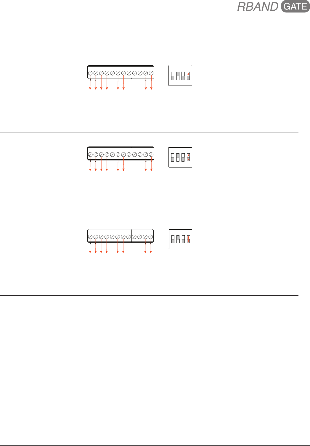
NORMALLY CLOSED ADDENDUM:
Removable Connector Assignments by Manufacturer
All-O-Matic
CS1 C1 BS1 CS2 C2 BS2 NO3 C3
COM.A TEST
12/24 AC/DC
+ -
+12 or 24 VDC
GROUND
MON_CLOSE
COMMON
MON_OPEN
COMMON
COMMON
MON-12 VDC
ON
1 2 3 4
DIP Switch #4
• Turn to on
HySecurity
CS1 C1 BS1 CS2 C2 BS2 NO3 C3
COM.A TEST
12/24 AC/DC
+ -
+24 VDC
COMMON*
S1, S2, S3
SENSOR COM
S1, S2, S3
SENSOR COM
SENSOR COM
+24 VDC
ON
1 2 3 4
DIP Switch #4
• On to run
• Off to test
* Not “Sensor Common”
Maximum Controls
CS1 C1 BS1 CS2 C2 BS2 NO3 C3
COM.A TEST
12/24 AC/DC
+ -
12 or 24 VDC*
GND*
EDGE 1**
GND**
EDGE 2**
GND**
GND**
+12 VDC**
ON
1 2 3 4
DIP Switch #4
• Turn to on
* Main board
** MC200 Motor Controller