JDTECK JD55-PR RF Repeater System User Manual manual
JDTECK INC RF Repeater System manual
UserManual.wiki
>
JDTECK
>
JD55 PR User Manual
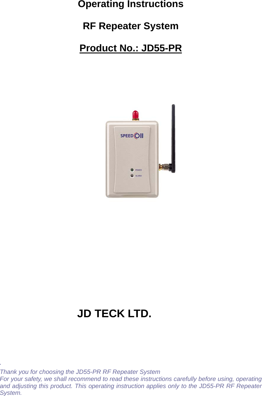
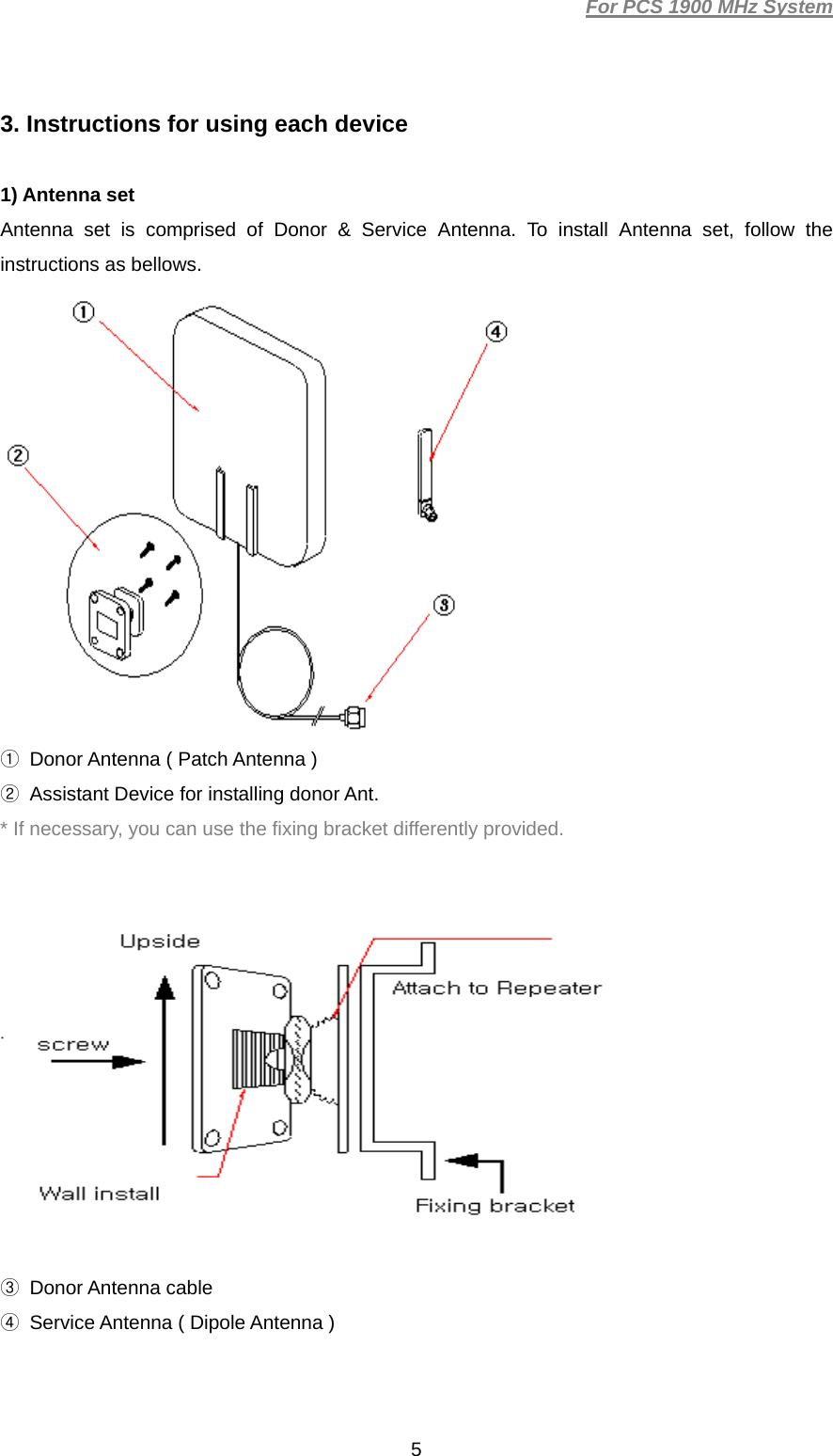
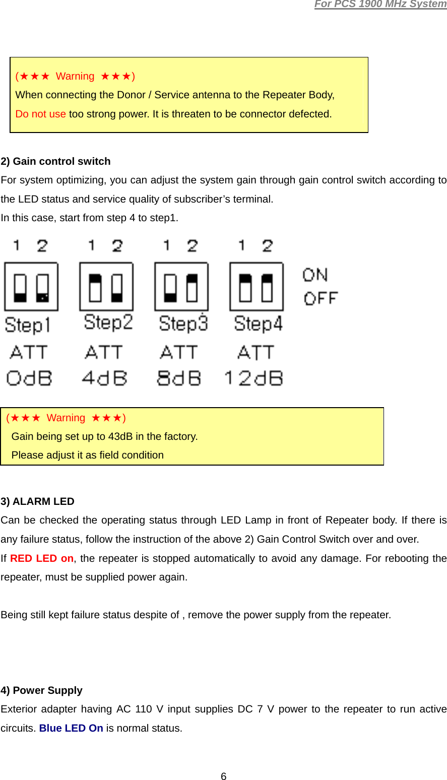
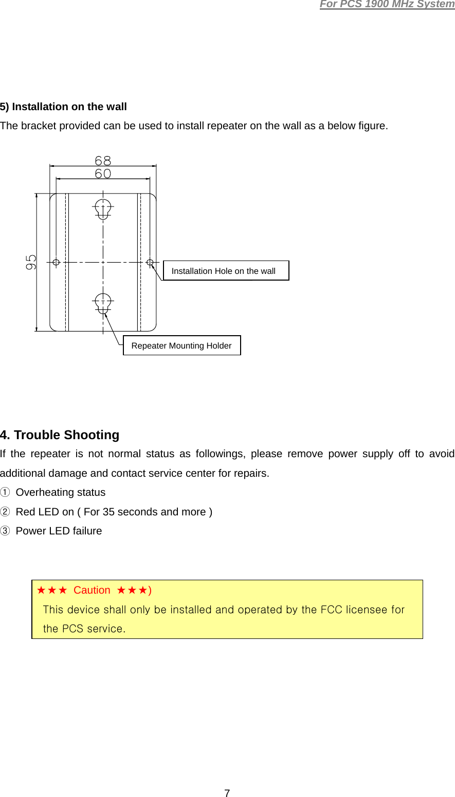
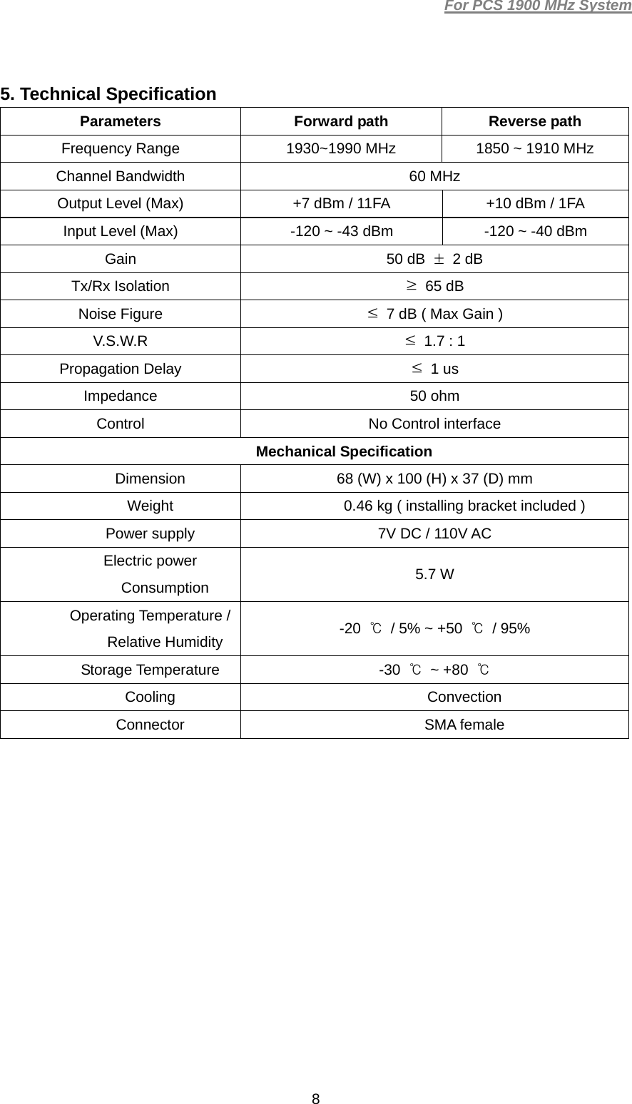
Users Manual
Navigation menu
Upload a User Manual
Namespaces
Wiki Guide
HTML
PDF
Info
Views
User Manual
Discussion / Help
Navigation