Users Manual
Thank you for choosing the JD55-PR RF Repeater System
For your safety, we shall recommend to read these instructions carefully before using, operating
and adjusting this product. This operating instruction applies only to the JD55-PR RF Repeater
System.
Operating Instructions
RF Repeater System
Product No.: JD55-PR
JD TECK LTD.
.
For PCS 1900 MHz System
2
The JD55-PR RF Repeater System is a bi-directional amplifier designed specially for in-
building RF Coverage extension ( about 100 ㎡ and more) for cellular services.
If you have a coverage problem in your home, office, small shop and restaurant, the JD55-PR
RF Repeater System will be a proper solution for your needs.
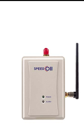
1. Basic Description of Each Part

For PCS 1900 MHz System
3
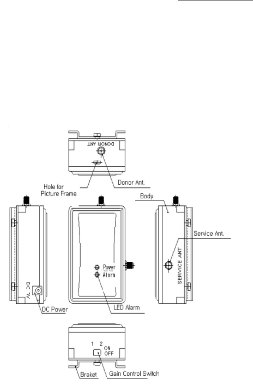
2. Function of Each part
1) DONOR ANT.
Port for connecting Donor antenna ( Patch Antenna )
2) SERVICE ANT.
Port for connecting Service antenna ( Dipole Antenna )
3) GAIN CONTROL SWITCH
Switch for controlling the system gain to optimize the service environment of Repeater.
For using this function, refer to the instructions of LED Alarm and Gain Control Switch as
following pages.
4) ALARM LED
There are two LED indicators on the unit. One is for displaying the Power Input Status, the other
is for operating status.
a. Power LED
The power indicator, marked “ Power “ acts as power alarm. It monitors the function of the
power supply.
Blue LED ON : Normal Status
LED Status Red LED ON : Power supply failure
b. Automatic Shutdown Function
If there are some abnormal output powers on the uplink or downlink path, the repeater will be
shutdown automatically to avoid any problem.
Blue LED ON : Normal Status
LED Status Red LED ON : Failure Status
If the red indicator lights up, it is designed that the related circuit operates to have the repeater
shutdown to protect repeater itself. Despite several corrections, the indicator is still kept red on,
it should be secured the isolation more between the donor antenna and service antenna.
For PCS 1900 MHz System
4
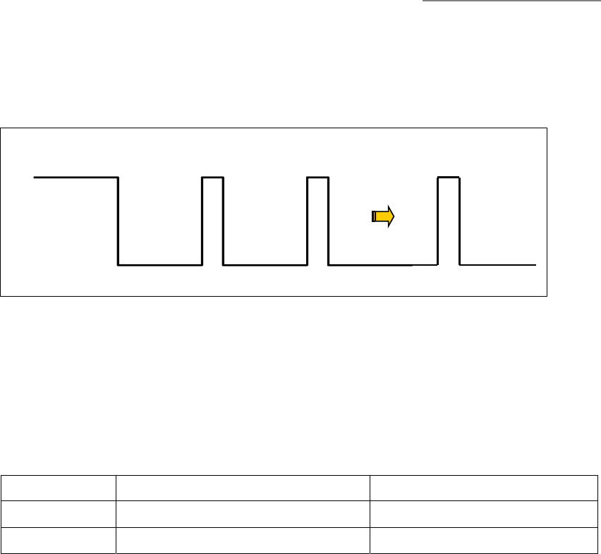
* Shutdown Algorithm
The embedded detector of repeater is designed to detect whether the RF output power of the
repeater exceeds a prescribe limit on the downlink or uplink. If it catches some overpowers
during 10 seconds and more, the repeater itself shutdown automatically.
Meanwhile, the repeater operates as the above algorithm during shutdown.
* Shutdown Level
Specifications Remarks
Downlink +15 ± 2 dBm / Total Red LED ON
Uplink +15 ± 2 dBm / 1FA Red LED ON
5) DC POWER SUPPLY
Port for connecting exterior power adapter that supplies DC7V power to the repeater..
6) HOLE for PICTURE FRAME
Hole for hanging the picture provided ( Optional ).
Detection
for 10 second
S/D for 10 seconds
Input
Detection
for 1 second
S/D for 10 seconds
Detection
for 1 second Detection
for 1 second
S/D for 30 minutes S/D completely
For PCS 1900 MHz System
5
3. Instructions for using each device
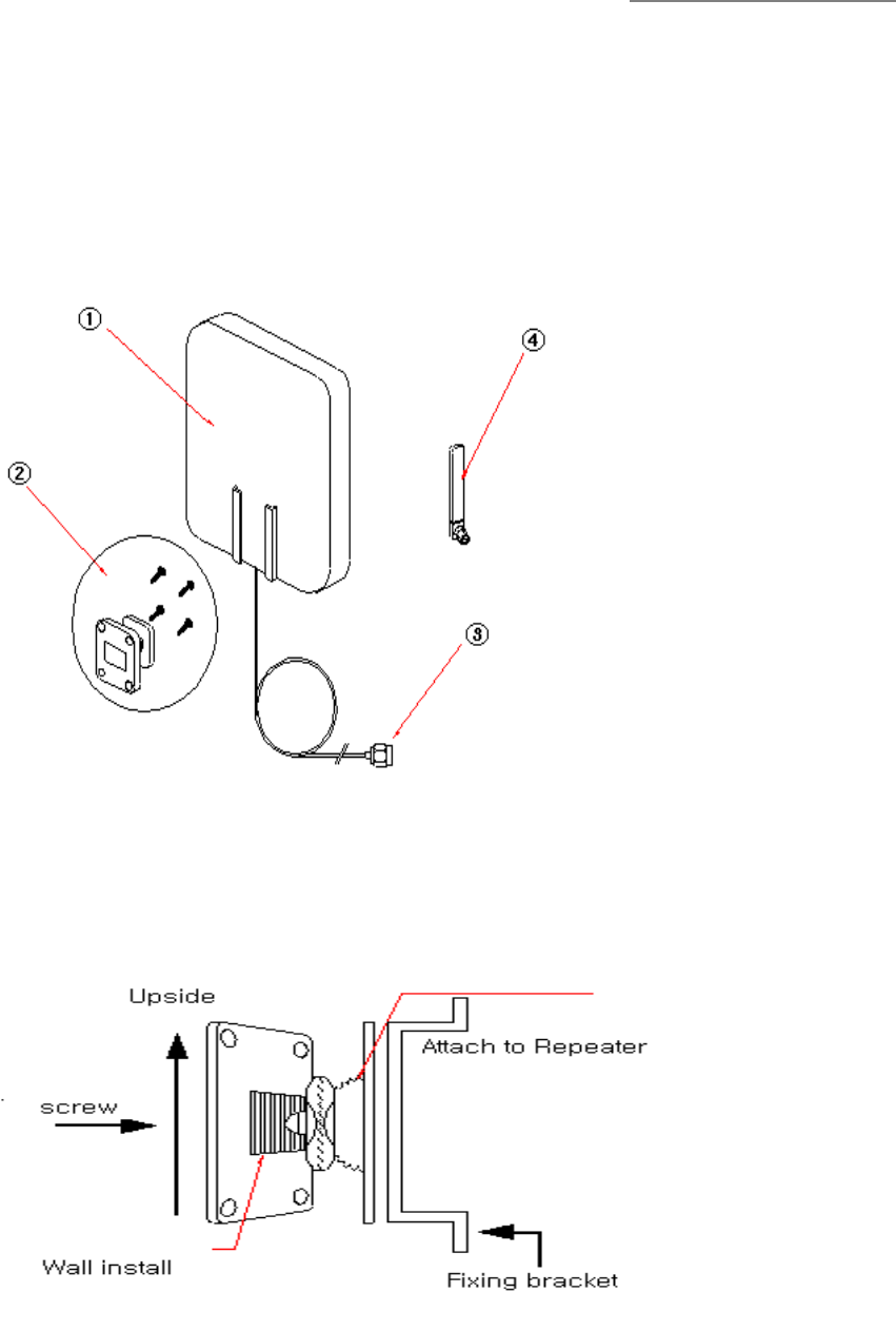
1) Antenna set
Antenna set is comprised of Donor & Service Antenna. To install Antenna set, follow the
instructions as bellows.
① Donor Antenna ( Patch Antenna )
② Assistant Device for installing donor Ant.
* If necessary, you can use the fixing bracket differently provided.
③ Donor Antenna cable
④ Service Antenna ( Dipole Antenna )
For PCS 1900 MHz System
6
(★★★ Warning ★★★)
When connecting the Donor / Service antenna to the Repeater Body,
Do not use too strong power. It is threaten to be connector defected.
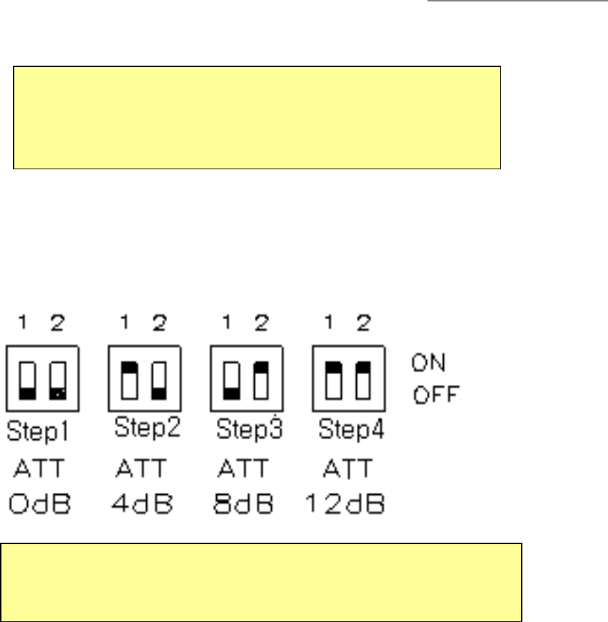
2) Gain control switch
For system optimizing, you can adjust the system gain through gain control switch according to
the LED status and service quality of subscriber’s terminal.
In this case, start from step 4 to step1.
3) ALARM LED
Can be checked the operating status through LED Lamp in front of Repeater body. If there is
any failure status, follow the instruction of the above 2) Gain Control Switch over and over.
If RED LED on, the repeater is stopped automatically to avoid any damage. For rebooting the
repeater, must be supplied power again.
Being still kept failure status despite of , remove the power supply from the repeater.
4) Power Supply
Exterior adapter having AC 110 V input supplies DC 7 V power to the repeater to run active
circuits. Blue LED On is normal status.
(★★★ Warning ★★★)
Gain being set up to 43dB in the factory.
Please adjust it as field condition
For PCS 1900 MHz System
7
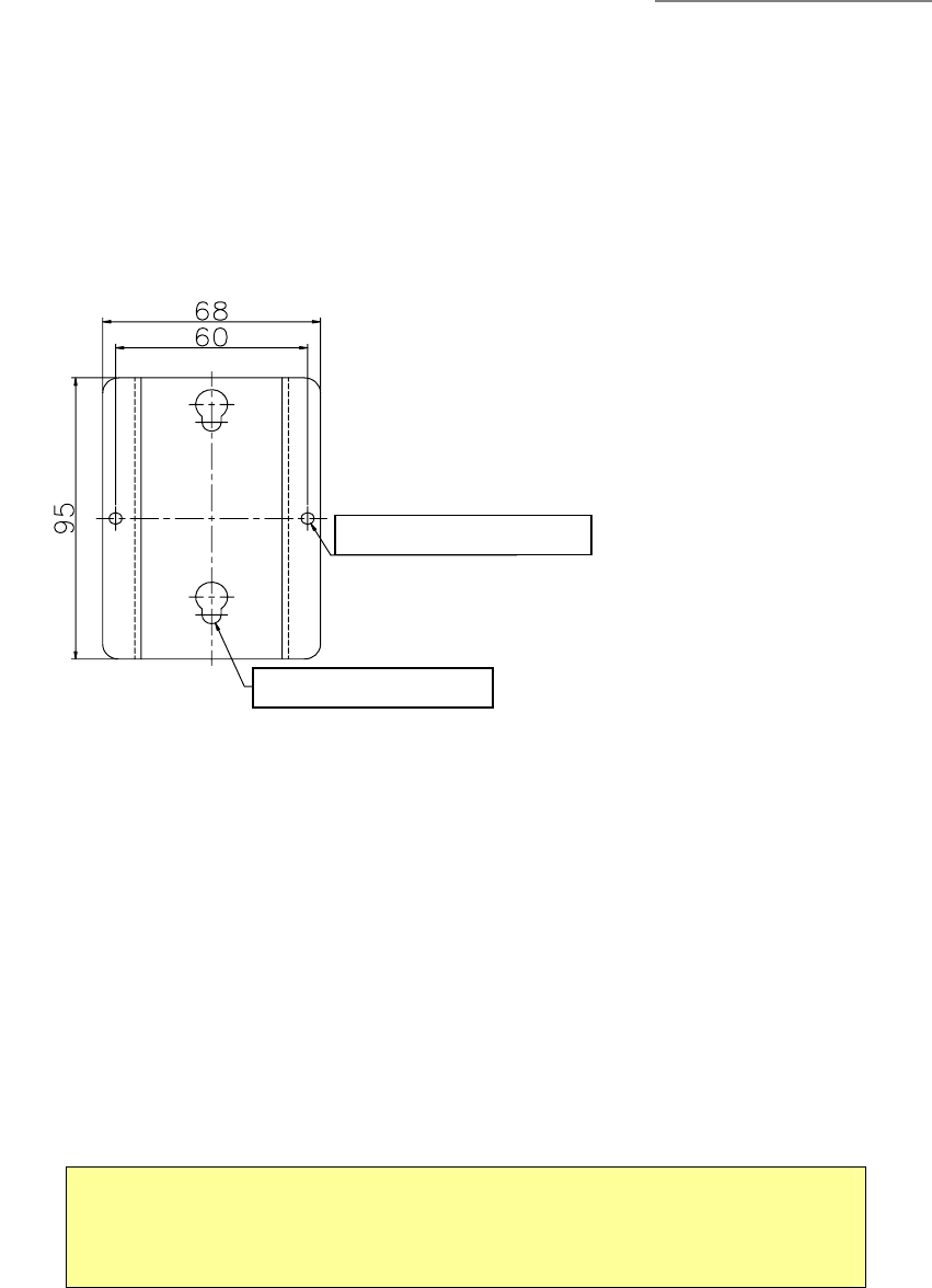
5) Installation on the wall
The bracket provided can be used to install repeater on the wall as a below figure.
4. Trouble Shooting
If the repeater is not normal status as followings, please remove power supply off to avoid
additional damage and contact service center for repairs.
① Overheating status
② Red LED on ( For 35 seconds and more )
③ Power LED failure
(★★★ Caution ★★★)
This device shall only be installed and operated by the FCC licensee for
the PCS service.
Installation Hole on the wall
Repeater Mounting Holder

For PCS 1900 MHz System
8
5. Technical Specification
Parameters Forward path Reverse path
Frequency Range 1930~1990 MHz 1850 ~ 1910 MHz
Channel Bandwidth 60 MHz
Output Level (Max) +7 dBm / 11FA +10 dBm / 1FA
Input Level (Max) -120 ~ -43 dBm -120 ~ -40 dBm
Gain 50 dB ± 2 dB
Tx/Rx Isolation ≥ 65 dB
Noise Figure ≤ 7 dB ( Max Gain )
V.S.W.R ≤ 1.7 : 1
Propagation Delay ≤ 1 us
Impedance 50 ohm
Control No Control interface
Mechanical Specification
Dimension 68 (W) x 100 (H) x 37 (D) mm
Weight 0.46 kg ( installing bracket included )
Power supply 7V DC / 110V AC
Electric power
Consumption 5.7 W
Operating Temperature /
Relative Humidity -20 ℃ / 5% ~ +50 ℃ / 95%
Storage Temperature -30 ℃ ~ +80 ℃
Cooling Convection
Connector SMA female

For PCS 1900 MHz System
9
6. Package Contains
No. Item Descriptions Q/ty Remarks
1 Repeater Speed Home Repeater 1
Patch antenna for outdoor 1 Donor Antenna
Dipole antenna for indoor 1 Service Antenna
Assistant device 1
2 Antenna
Screws 4
3 Power supply AC_DC Adapter 1
Assistants 1
Screws 2
4 Fixing device
Assistant fixing device 1
Picture 1 Optional
5 Frame Assistant for fixing frame 1 Optional,
Screws included