JL MARINE SYSTEMS EA041 MICRO SHALLOW WATER ANCHOR User Manual Instructions
JL MARINE SYSTEMS, INC. MICRO SHALLOW WATER ANCHOR Instructions
UserManual.wiki
>
JL MARINE SYSTEMS
>
EA041 User Manual
>
Instructions
Contents
1.
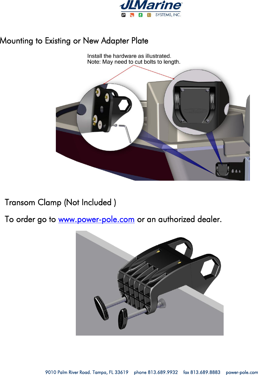
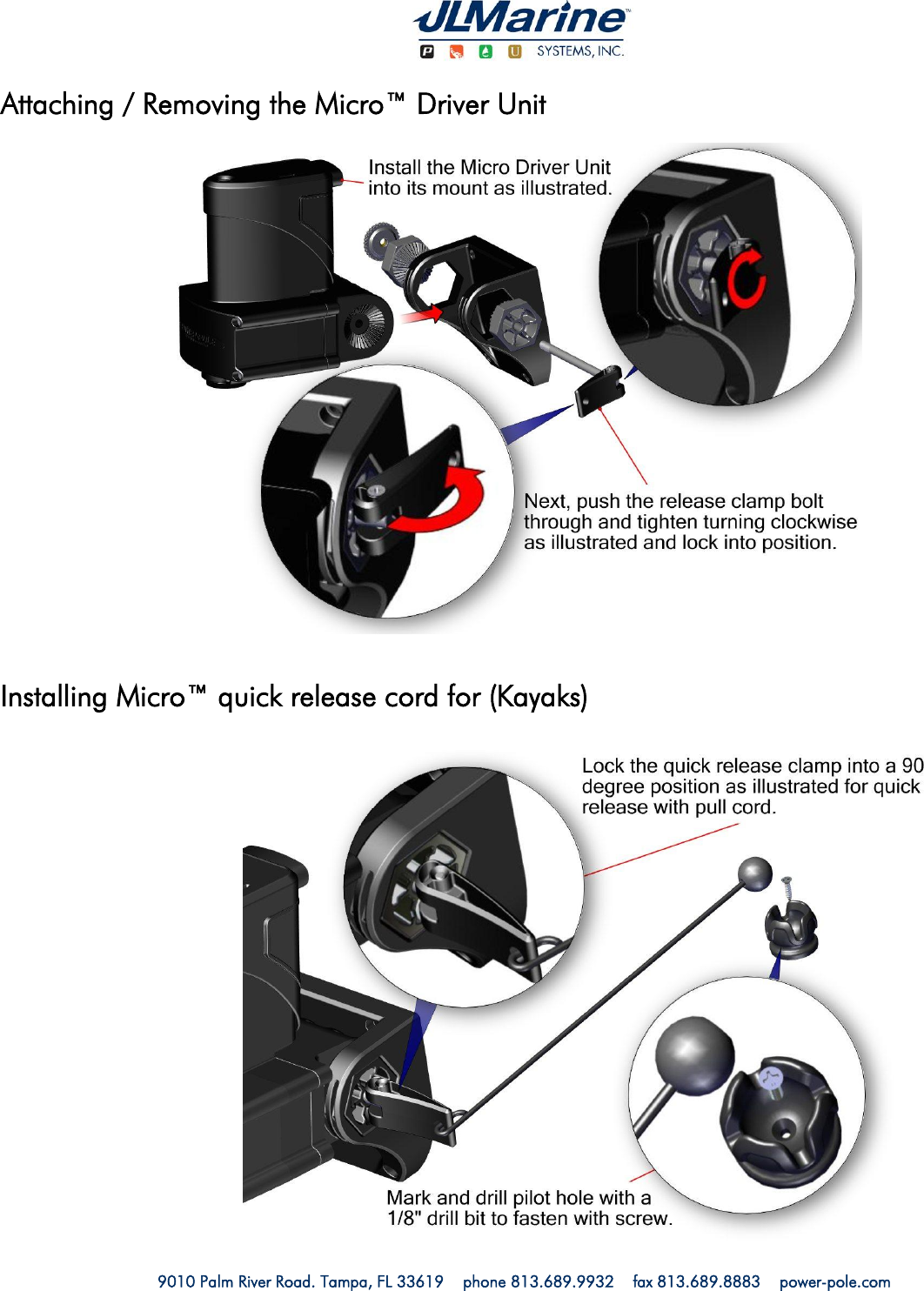
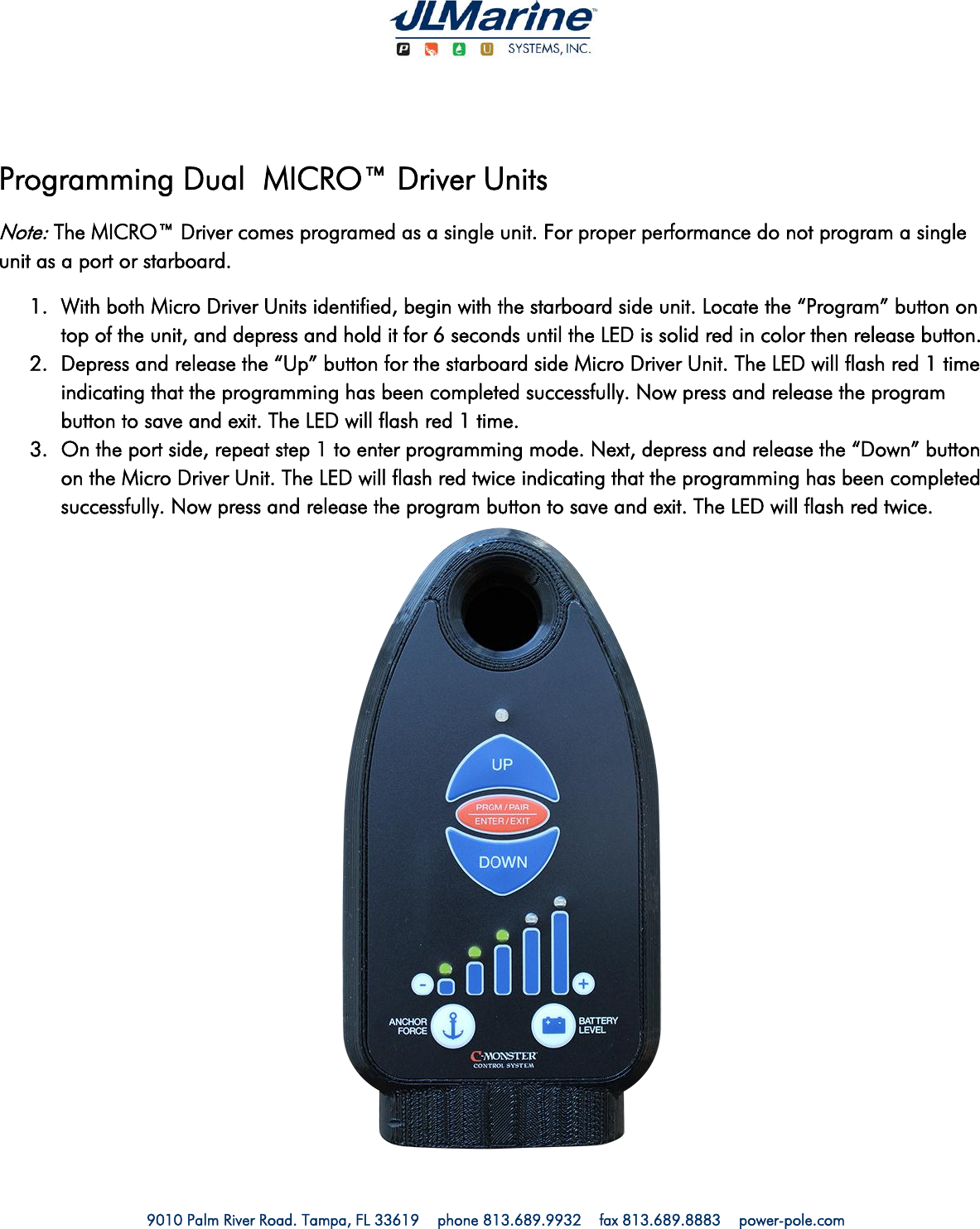
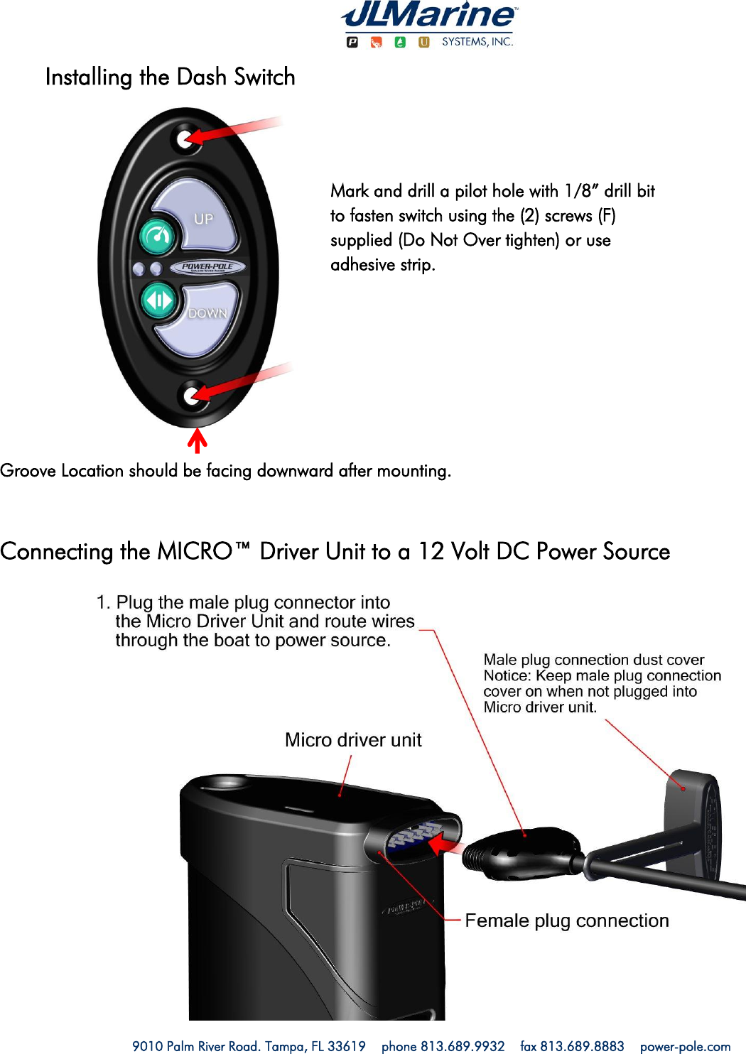
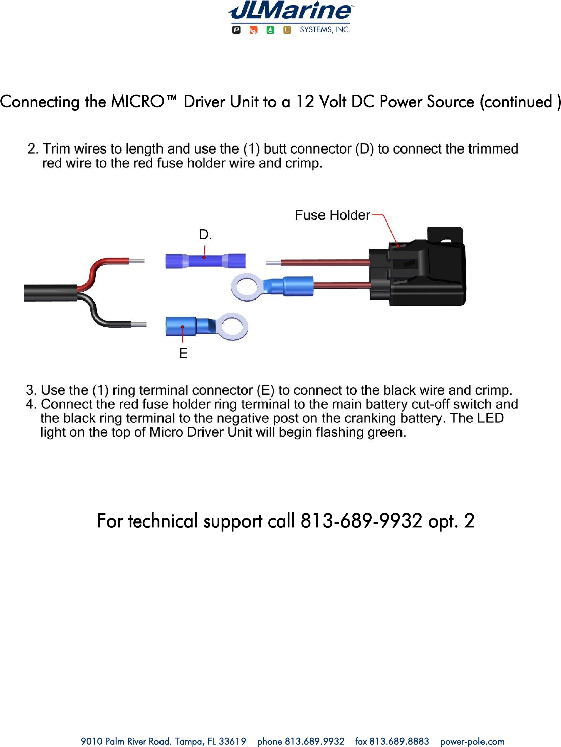
Instructions
2.
Bluetooth Module
Instructions
Navigation menu
Upload a User Manual
Namespaces
Wiki Guide
HTML
PDF
Info
Views
User Manual
Discussion / Help
Navigation