JL MARINE SYSTEMS EA041 MICRO SHALLOW WATER ANCHOR User Manual Instructions
JL MARINE SYSTEMS, INC. MICRO SHALLOW WATER ANCHOR Instructions
Contents
- 1. Instructions
- 2. Bluetooth Module
Instructions
9010 Palm River Road. Tampa, FL 33619 phone 813.689.9932 fax 813.689.8883 power-pole.com
Installation Manual
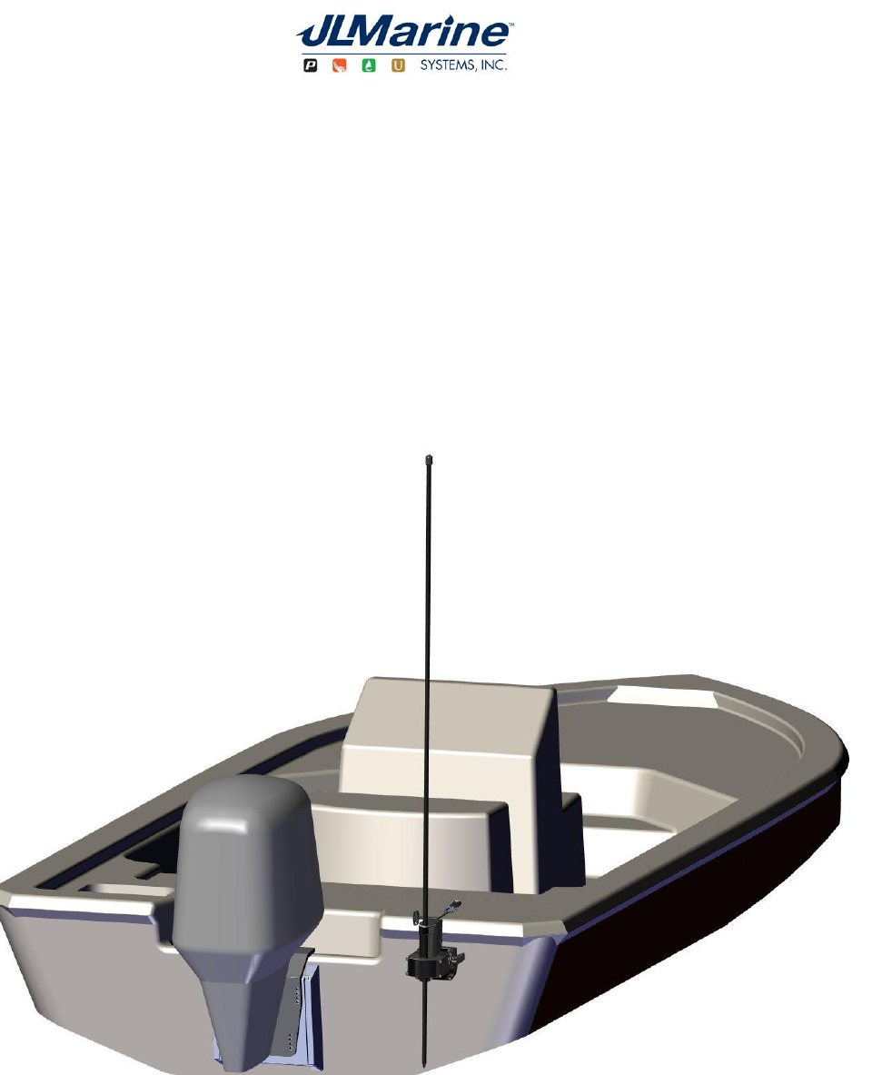
Power-Pole Micro™ Shallow Water Anchor
9010 Palm River Road. Tampa, FL 33619 phone 813.689.9932 fax 813.689.8883 power-pole.com
Congratulations on your purchase of a Power-Pole
Micro™ shallow water anchor featuring C-Monster
Control System. It has been designed, engineered,
and manufactured to provide the best possible
performance and dependability for years of enjoyment.
Please read all installation instructions carefully. The
information contained here describes the proper
procedures for safely installing your Power-Pole
shallow water anchor.
Caution:
Do not use the Power-Pole shallow water anchor as your
primary anchorage. Never leave your boat unattended
while anchored solely with the Power-Pole shallow water
anchor.

9010 Palm River Road. Tampa, FL 33619 phone 813.689.9932 fax 813.689.8883 power-pole.com
A. Qty. (4) 5/16” x 3.5 “ all thread transom mount bolts
B. Qty. (4) 5/16” fender washers
C. Qty. (4) 5/16” tall brass nuts
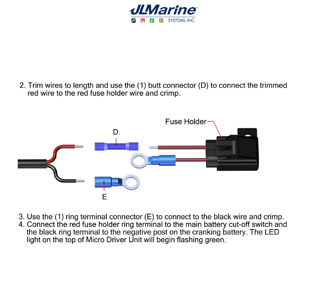
D. Qty. (1) butt connecter
E. Qty. (1) ring terminal
F. Qty. (3) #8 x ¾” flat head screws
G. Qty. (1) adhesive strip
H. Qty. (1) Micro™ pull cord (Kayaks)
I. Qty. (1) Micro™ cord holder
J. Qty. (1) Power cord plug
K. Qty. (1) Standard Key-Fob
Included Items:
Installation Tools
½” Wrench
½” Socket with ratchet
Electric or battery operated drill
5/16” & 1/8” drill bit
Heat gun
Marine grade sealant
Fine point marker
Wire cutters
Wire strippers
Wire terminal crimpers
¼” Allen wrench
Phillips screwdriver
9010 Palm River Road. Tampa, FL 33619 phone 813.689.9932 fax 813.689.8883 power-pole.com
Mounting Options-
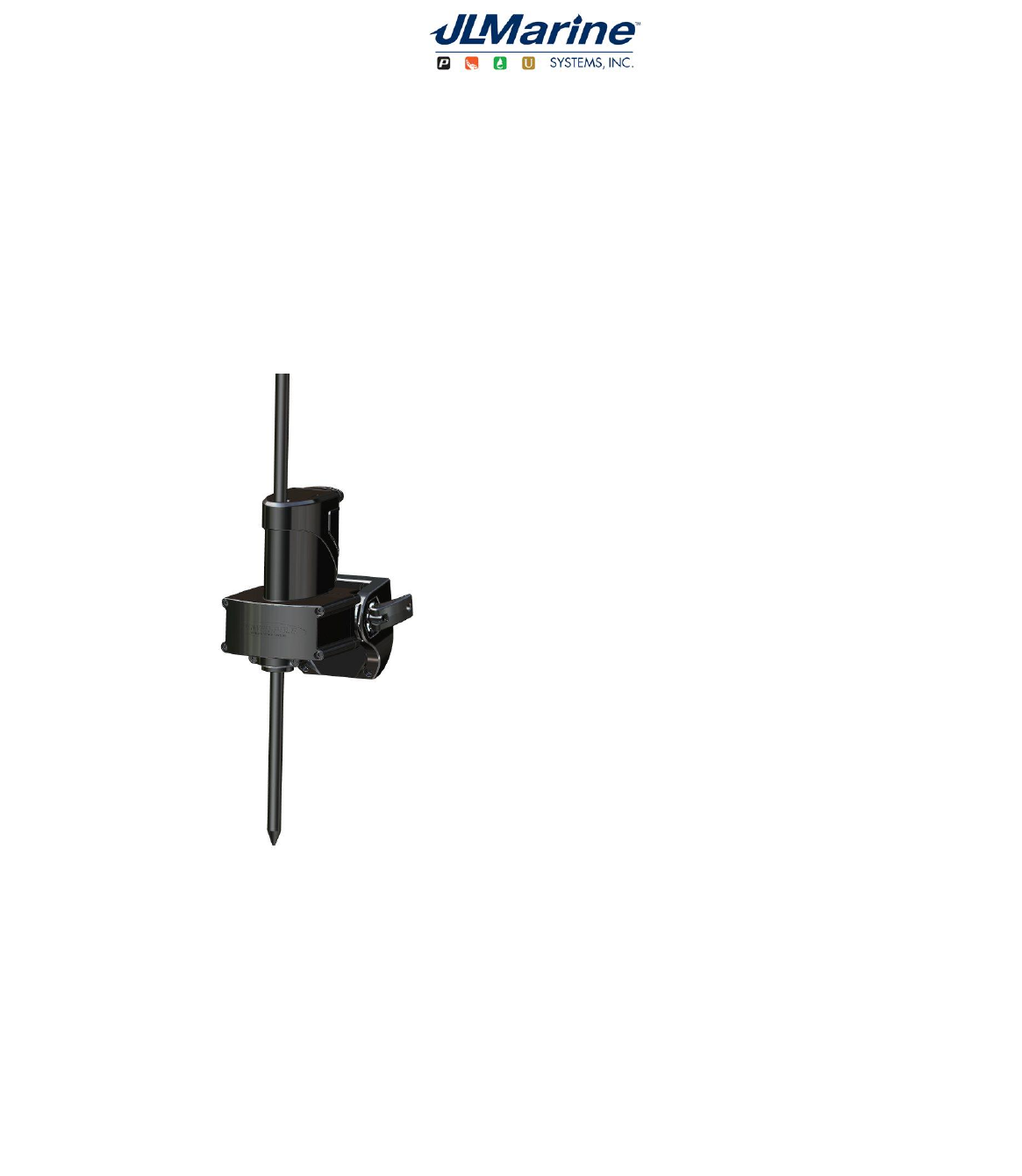
Important: In all options it is recommended that the bottom of the Micro™ driver unit be mounted above
the water line of the boat.
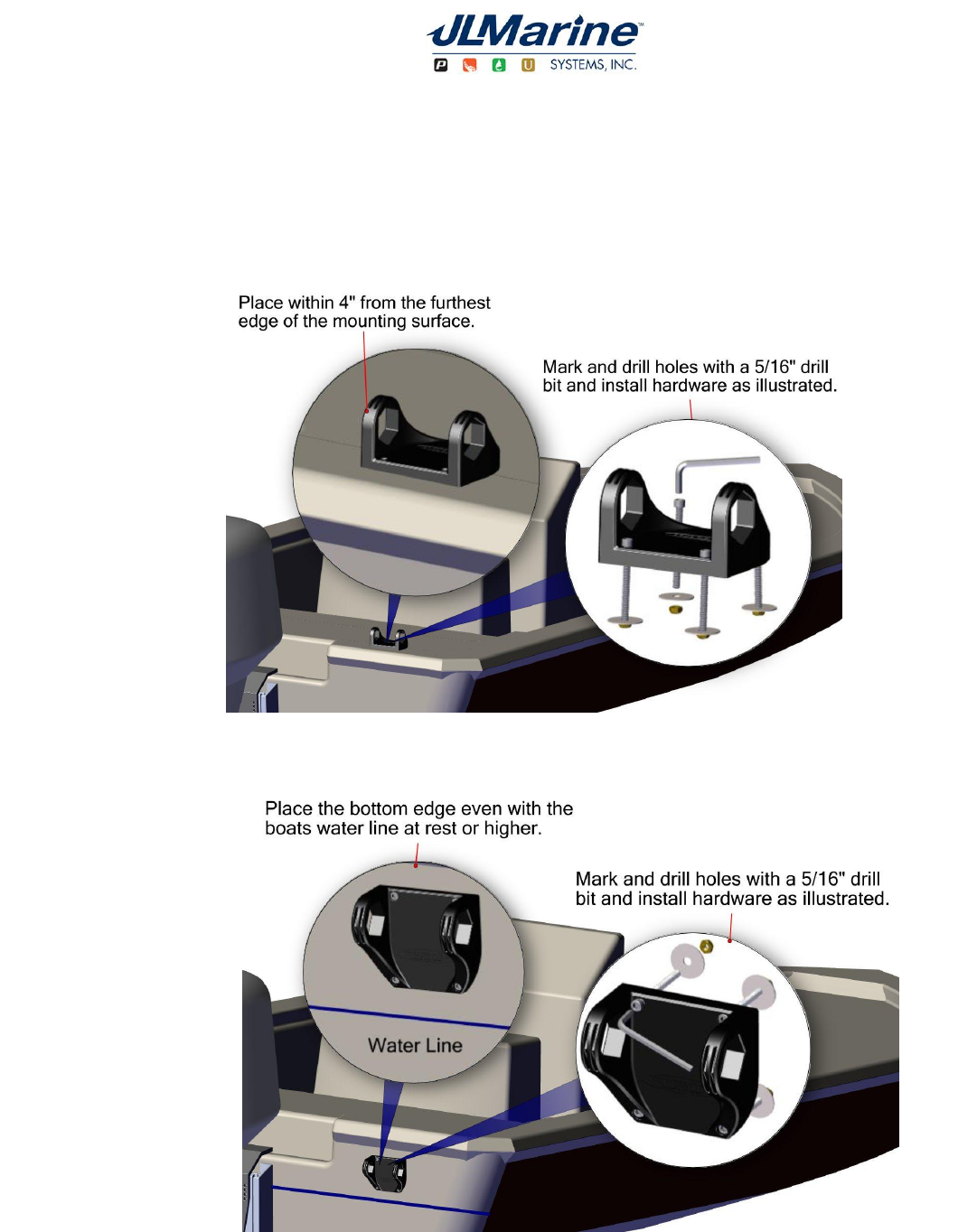
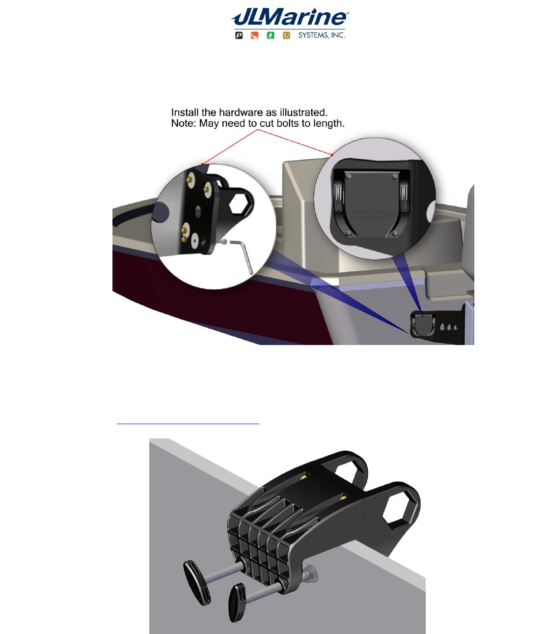
Deck Mount Installation
Transom Mount Installation
9010 Palm River Road. Tampa, FL 33619 phone 813.689.9932 fax 813.689.8883 power-pole.com
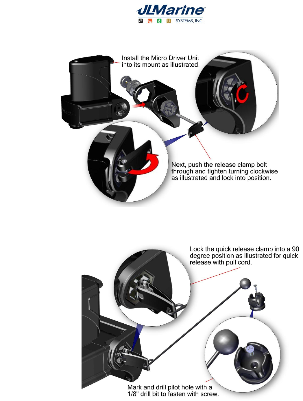
Attaching / Removing the Micro™ Driver Unit
Installing Micro™ quick release cord for (Kayaks)
9010 Palm River Road. Tampa, FL 33619 phone 813.689.9932 fax 813.689.8883 power-pole.com
Programming Dual MICRO™ Driver Units
Note:
The MICRO™ Driver comes programed as a single unit. For proper performance do not program a single
unit as a port or starboard.
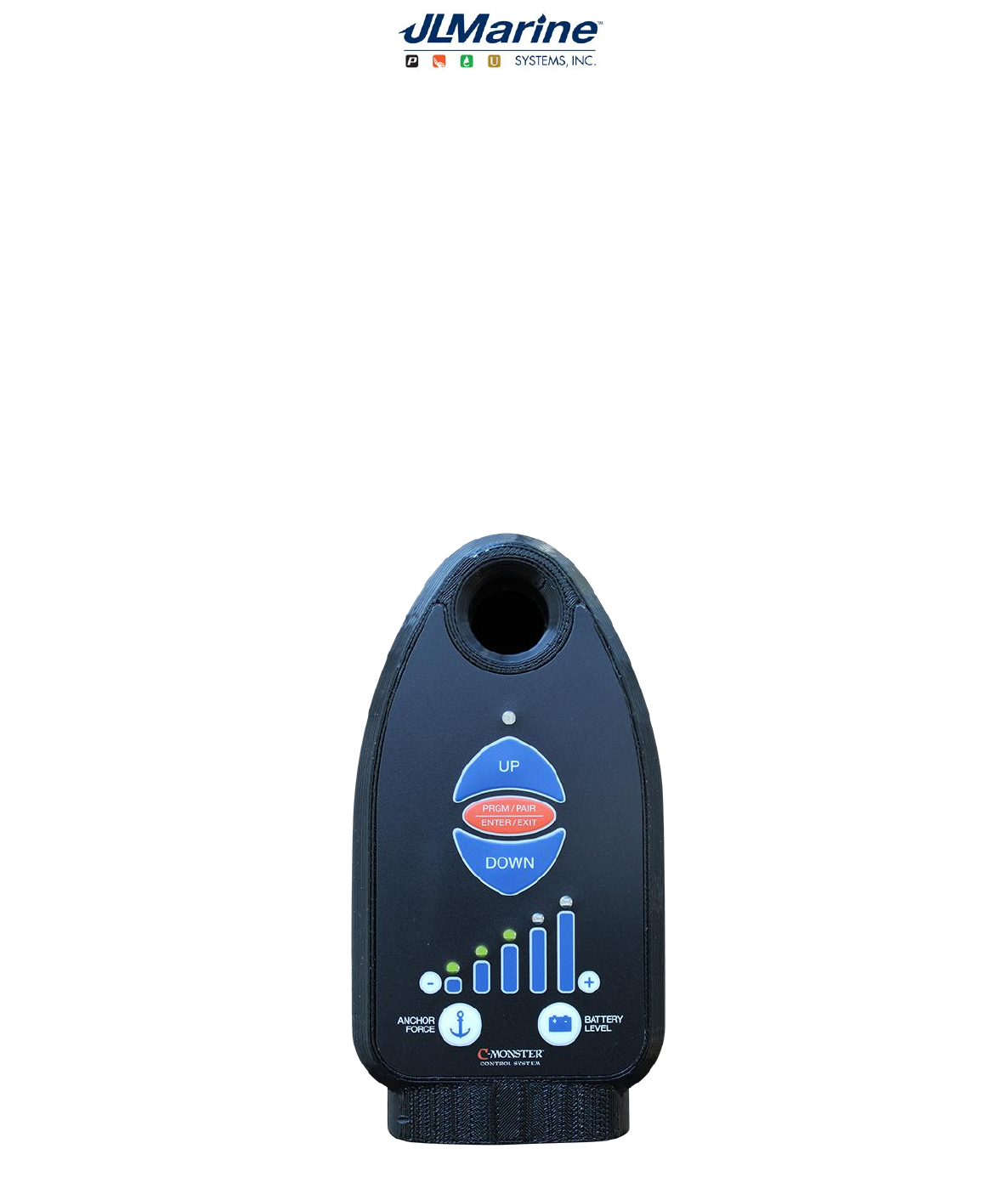
1. With both Micro Driver Units identified, begin with the starboard side unit. Locate the “Program” button on
top of the unit, and depress and hold it for 6 seconds until the LED is solid red in color then release button.
2. Depress and release the “Up” button for the starboard side Micro Driver Unit. The LED will flash red 1 time
indicating that the programming has been completed successfully. Now press and release the program
button to save and exit. The LED will flash red 1 time.
3. On the port side, repeat step 1 to enter programming mode. Next, depress and release the “Down” button
on the Micro Driver Unit. The LED will flash red twice indicating that the programming has been completed
successfully. Now press and release the program button to save and exit. The LED will flash red twice.
9010 Palm River Road. Tampa, FL 33619 phone 813.689.9932 fax 813.689.8883 power-pole.com
Mark and drill a pilot hole with 1/8” drill bit
to fasten switch using the (2) screws (F)
supplied (Do Not Over tighten) or use
adhesive strip.
Groove Location should be facing downward after mounting.
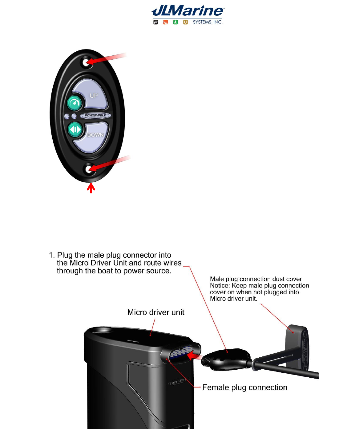
Installing the Dash Switch
Connecting the MICRO™ Driver Unit to a 12 Volt DC Power Source
9010 Palm River Road. Tampa, FL 33619 phone 813.689.9932 fax 813.689.8883 power-pole.com
Connecting the MICRO™ Driver Unit to a 12 Volt DC Power Source (continued )
For technical support call 813-689-9932 opt. 2

9010 Palm River Road. Tampa, FL 33619 phone 813.689.9932 fax 813.689.8883 power-pole.com
FCC Part 15.19 Warning Statement-
THIS DEVICE COMPLIES WITH PART 15 OF THE FCC RULES. OPERATION IS SUBJECT TO THE FOLLOWING TWO
CONDITIONS: (1) THIS DEVICE MAY NOT CAUSE HARMFUL INTERFERENCE, AND (2) THIS DEVICE MUST ACCEPT ANY
INTERFERENCE RECEIVED, INCLUDING INTERFERENCE THAT MAY CAUSE UNDESIRED OPERATION.
FCC Part 15.21 Warning Statement-
NOTE: THE GRANTEE IS NOT RESPONSIBLE FOR ANY CHANGES OR MODIFICATIONS NOT EXPRESSLY APPROVED BY
THE PARTY RESPONSIBLE FOR COMPLIANCE. SUCH MODIFICATIONS COULD VOID THE USER’S AUTHORITY TO
OPERATE THE EQUIPMENT.
FCC Part 15.105(b) Warning Statement-
NOTE: This equipment has been tested and found to comply with the limits for a Class B digital device, pursuant to
part 15 of the FCC Rules. These limits are designed to provide reasonable protection against harmful interference
in a residential installation. This equipment generates, uses and can radiate radio frequency energy and, if not
installed and used in accordance with the instructions, may cause harmful interference to radio
communications. However, there is no guarantee that interference will not occur in a particular installation. If this
equipment does cause harmful interference to radio or television reception, which can be determined by turning
the equipment off and on, the user is encouraged to try to correct the interference by one or more of the following
measures:
- Reorient or relocate the receiving antenna.
- Increase the separation between the equipment and receiver.
-Connect the equipment into an outlet on a circuit different from that to which the receiver is connected.
-Consult the dealer or an experienced radio/TV technician for help.
IC RSS-GEN, Sec 7.1.3 Warning Statement-
ENGLISH:
This device complies with Industry Canada license-exempt RSS standard(s). Operation is subject to the following
two conditions: (1) this device may not cause interference, and (2) this device must accept any interference,
including interference that may cause undesired operation of the device.
FRENCH:
Le présent appareil est conforme aux CNR d'Industrie Canada applicables aux appareils radio exempts de licence.
L'exploitation est autorisée aux deux conditions suivantes : (1) l'appareil ne doit pas produire de brouillage, et (2)
l'utilisateur de l'appareil doit accepter tout brouillage radioélectrique subi, même si le brouillage est susceptible
d'en compromettre le fonctionnement.
IC RSS-GEN, Sec 7.1.2 Warning Statement-
ENGLISH:
Under Industry Canada regulations, this radio transmitter may only operate using an antenna of a type and
maximum (or lesser) gain approved for the transmitter by Industry Canada. To reduce potential radio interference
to other users, the antenna type and its gain should be so chosen that the equivalent isotropically radiated power
(e.i.r.p.) is not more than that necessary for successful communication.
FRENCH:
Conformément à la réglementation d'Industrie Canada, le présent émetteur radio peut fonctionner avec une
antenne d'un type et d'un gain maximal (ou inférieur) approuvé pour l'émetteur par Industrie Canada. Dans le but
de réduire les risques de brouillage radioélectrique à l'intention des autres utilisateurs, il faut choisir le type
d'antenne et son gain de sorte que la puissance isotrope rayonnée quivalente (p.i.r.e.) ne dépassepas l'intensité
nécessaire à l'établissement d'une communication satisfaisante.