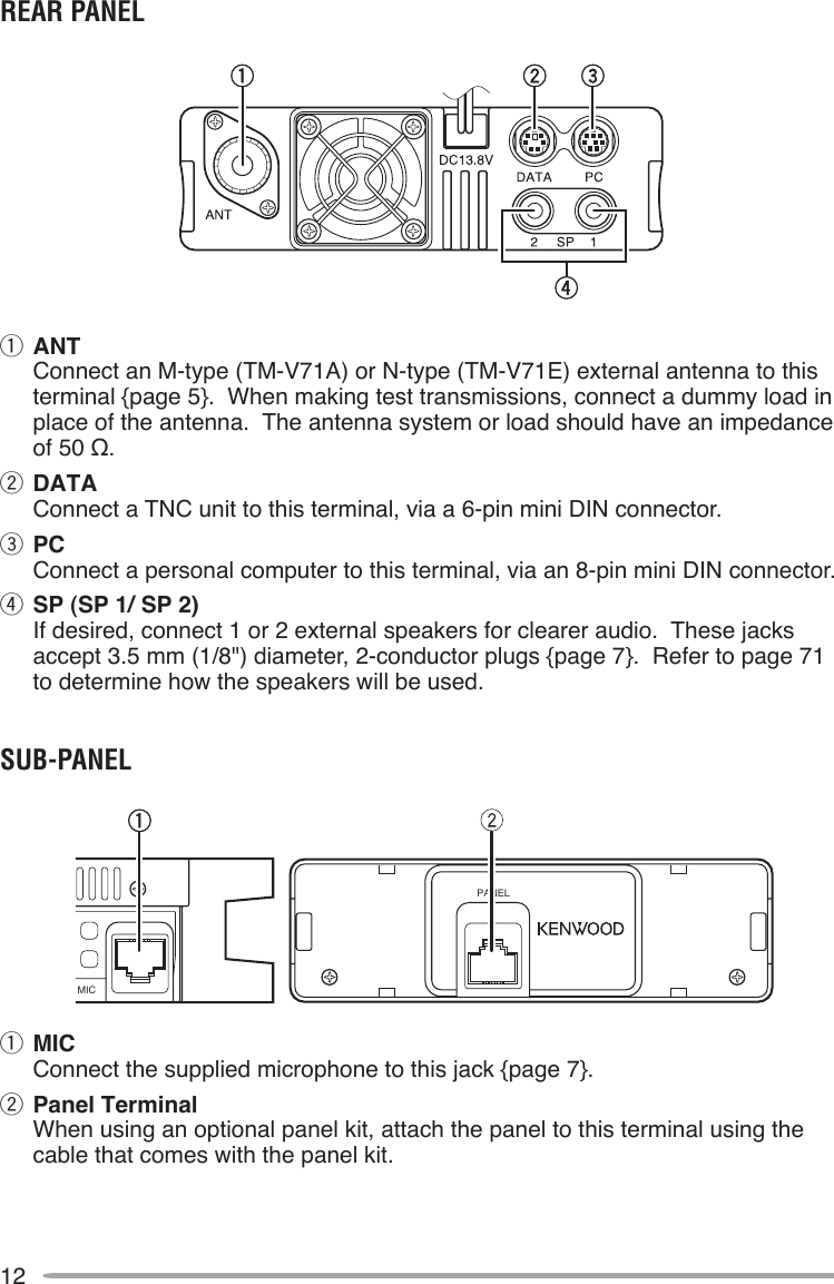
JVC KENWOOD 397700 Scanning Receiver User Manual Instruction Manual 1
JVC KENWOOD Corporation Scanning Receiver Instruction Manual 1
Contents
- 1. Instruction Manual 1
- 2. Instruction Manual 2
- 3. User Manual
- 4. User Instructions Guide
- 5. User Guide Instructions
Instruction Manual 1
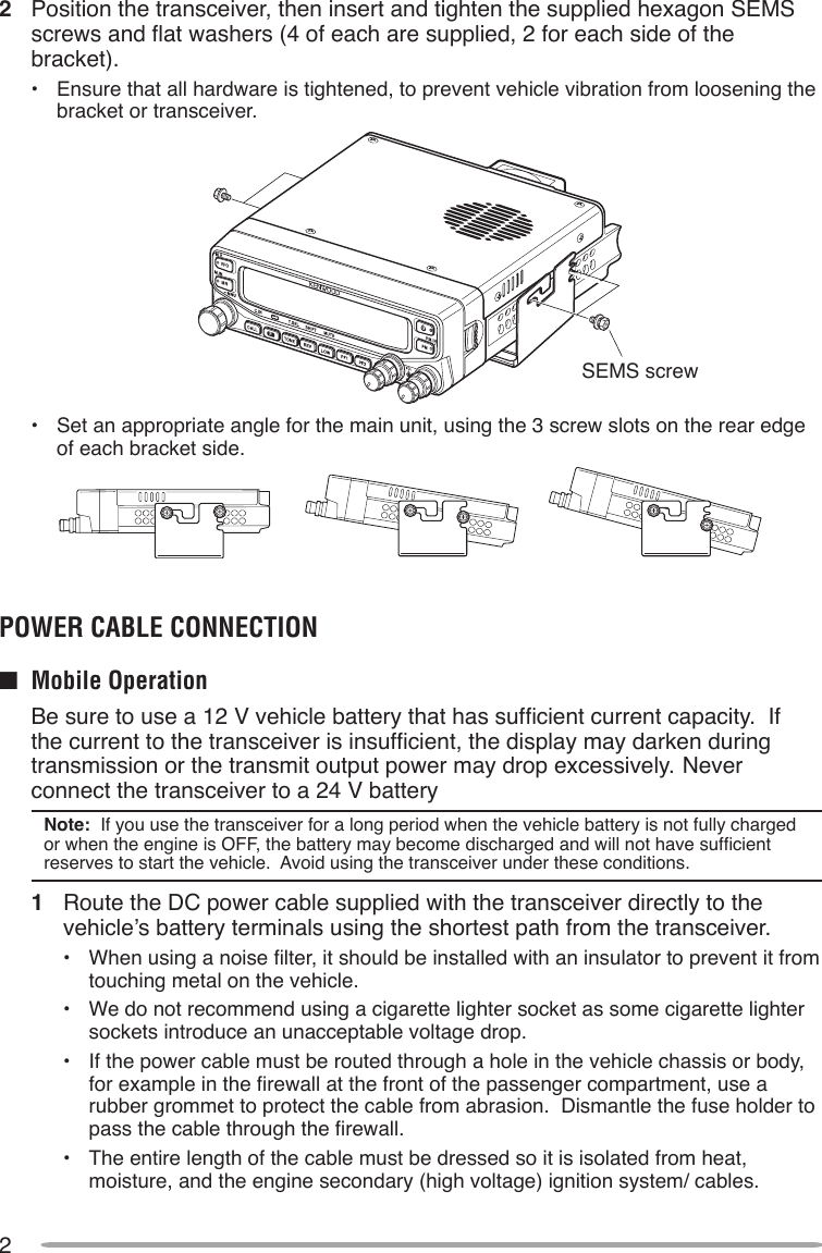
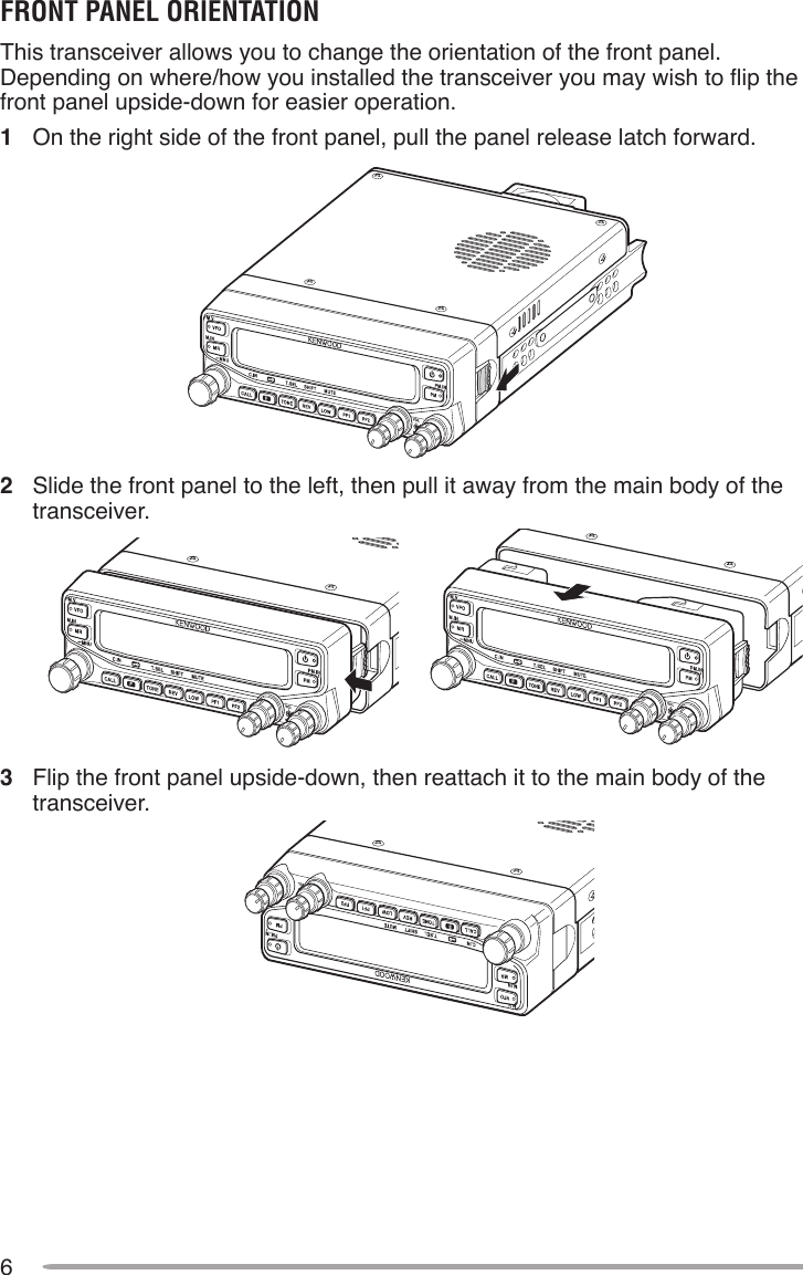
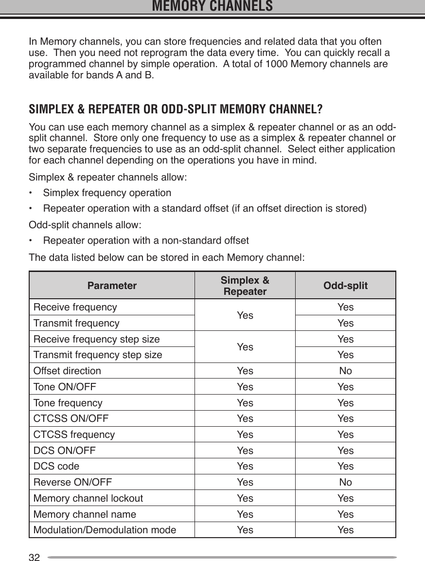
![Thank YouWe are grateful you decided to purchase this Kenwood FM transceiver. Kenwood always provides Amateur Radio products which surprise and excite serious hobbyists. This transceiver is no exception. Kenwood believes that this product will satisfy your requirements for both voice and data communications.FeaTuresThis transceiver has the following main features:• Enhanced Programmable Memory (PM) channels store virtually entire current operating environments for your quick recall.• Contains a total of 1000 Memory channels to program frequencies and other various data. Allows each Memory channel to be named using up to 8 alphanumeric characters.• Continuous Tone Coded Squelch System (CTCSS) or Digital Code Squelch (DCS) rejects unwanted calls from other stations.WriTing ConvenTions FolloWed in This ManualThe writing conventions described below have been followed to simplify instructions and avoid unnecessary repetition.Instruction ActionPress [KEY]. Momentarily press KEY.Press [KEY] (1s). Press and hold KEY for 1 second or longer.Press [KEY1], [KEY2]. Press KEY1 momentarily, release KEY1, then press KEY2.Press [F], [KEY]. Press the F key to enter Function mode, then press KEY to access its secondary function.Press [KEY] + Power ON. With the transceiver power OFF, press and hold KEY while turning the transceiver power ON.](https://usermanual.wiki/JVC-KENWOOD/397700.Instruction-Manual-1/User-Guide-768505-Page-2.png)
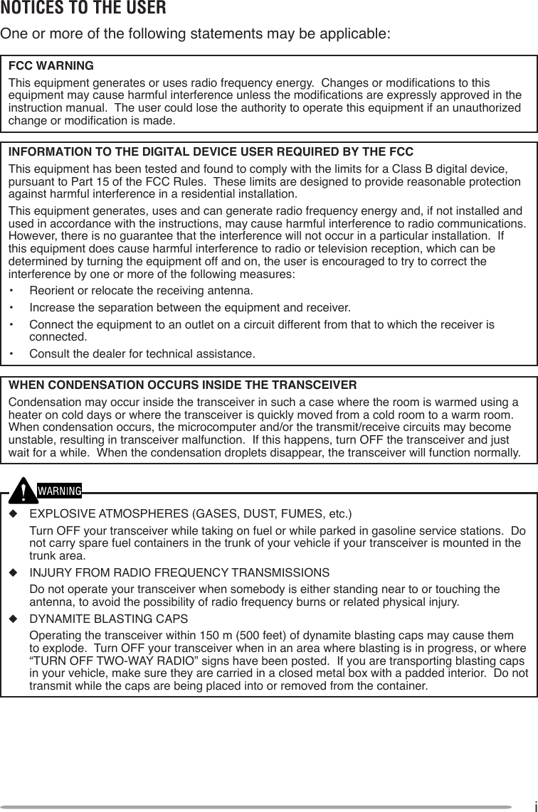
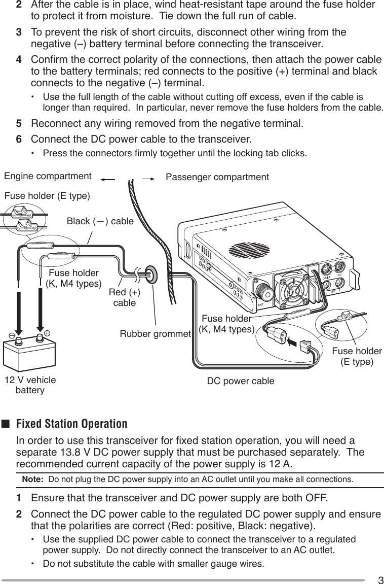
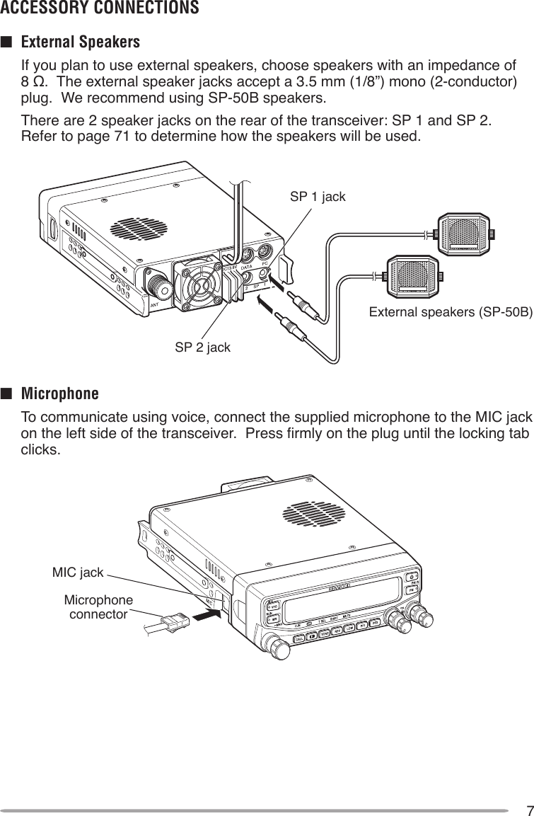
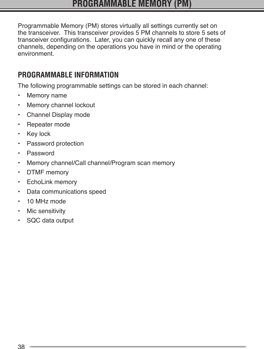
![8GETTING ACQUAINTEDFroNT PANElq VFO Press [VFO] to enter VFO mode {page 17}, then rotate the Tuning control to select an operating frequency. Press [VFO] (1s) to start VFO scan {page 43}. Press [F], [VFO] to copy the current Memory channel or Call channel to the VFO (memory shift) {page 36}.w MR Press [MR] to enter Memory Channel mode {page 18}, then rotate the Tuning control to select a Memory channel. Press [MR] (1s) to start Memory scan {page 44}. Select a Memory channel, then press [F], [MR] to store the current operating frequency in the Memory channel {page 33}.e Tuning Control Rotate to select an operating frequency or Memory channel, change the scan direction, select a tone frequency, etc. Press [F], then press the Tuning control to enter Menu mode {page 20}. Press [MHz] (1s) to start MHz scan {page 48} or Group scan {page 45}.r CALL Press [CALL] to select the Call channel. Press [CALL] (1s) to start Call scan {page 48}. Press [F], [CALL] to store the current operating frequency to the Call channel {page 33}.t F Press [F] to enter Function mode. Press [F] (1s) to turn the transceiver key lock function ON or OFF {page 63}.y TONE Press [TONE] to turn the Tone function ON. Continually press [TONE] to toggle the functions as follows: Tone ON >> CTCSS ON >> DCS ON >> OFF. While Tone, CTCSS, or DCS is ON, press [F], [TONE] to enter CTCSS or DCS setup mode.](https://usermanual.wiki/JVC-KENWOOD/397700.Instruction-Manual-1/User-Guide-768505-Page-16.png)
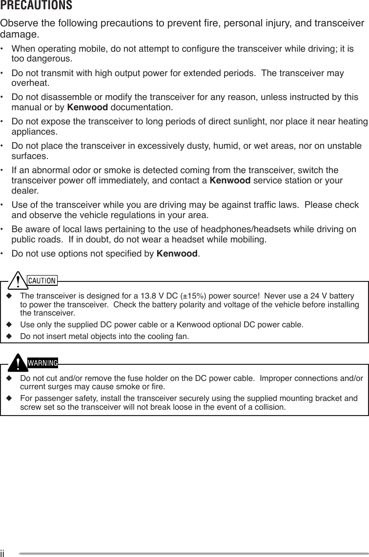
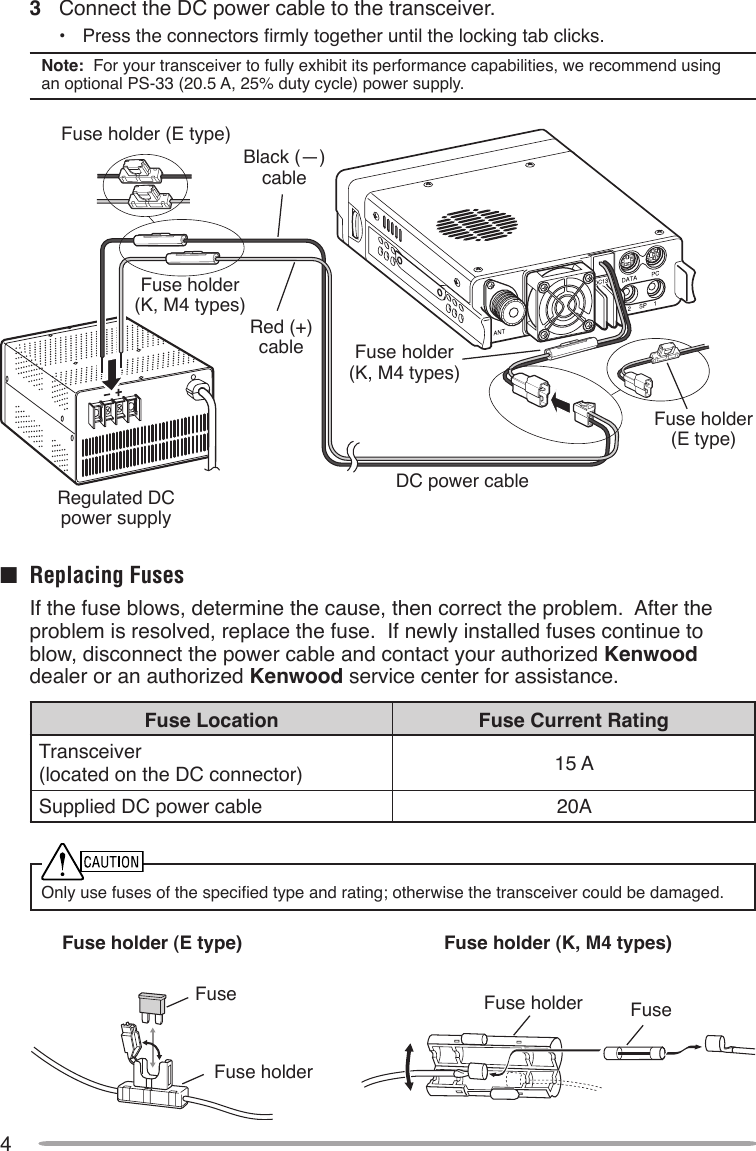
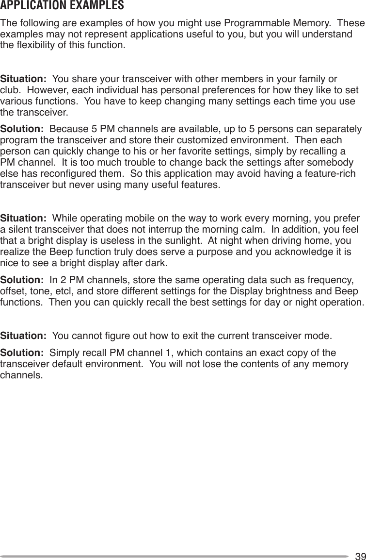
![9u REV Press [REV] to turn the Reverse function ON or OFF {page 30}. Press [REV] (1s) to turn the Automatic Simplex Checker ON {page 30}. Press [F], [REV] to enter Offset Direction selection mode. Each time you press [F], [REV], the offset direction toggles as follows: plus (+) direction –> minus (–) direction –> –7.6 MHz (E type only) –> OFF.i LOW Press [LOW] to toggle the transmit output power as follows: High Power (K, E types only) –> Middle Power –> Low Power {page 70}. Press [F], [LOW] to turn the Mute function ON or OFF {page 69},o PF1 Press [PF1] to activate its programmable function {page 66}. The default function is “Frequency Band Select”.!0 PF2 Press [PF2] to activate its programmable function {page 66}. The default function is “Operation Band Select”.!1 BAND SEL (VOL) Control Rotate the [BAND SEL] control to adjust the speaker volume {page 14}. Press the left [BAND SEL] to select the A band. Press the right [BAND SEL] to select the B band. Press [BAND SEL] (1s) to toggle between single and dual-band mode.!2 SQL Control Rotate the [SQL] control to adjust the squelch level. Clockwise opens the squelch and counterclockwise tightens the squelch {page 68}.!3 PM Press [PM] to enters the PM (Programmable Memory) channel selection mode {page 40}. Press [F], [PM] to enter PM Channel registration mode {page 40}.!4 Press to turn the transceiver power ON and OFF.](https://usermanual.wiki/JVC-KENWOOD/397700.Instruction-Manual-1/User-Guide-768505-Page-17.png)
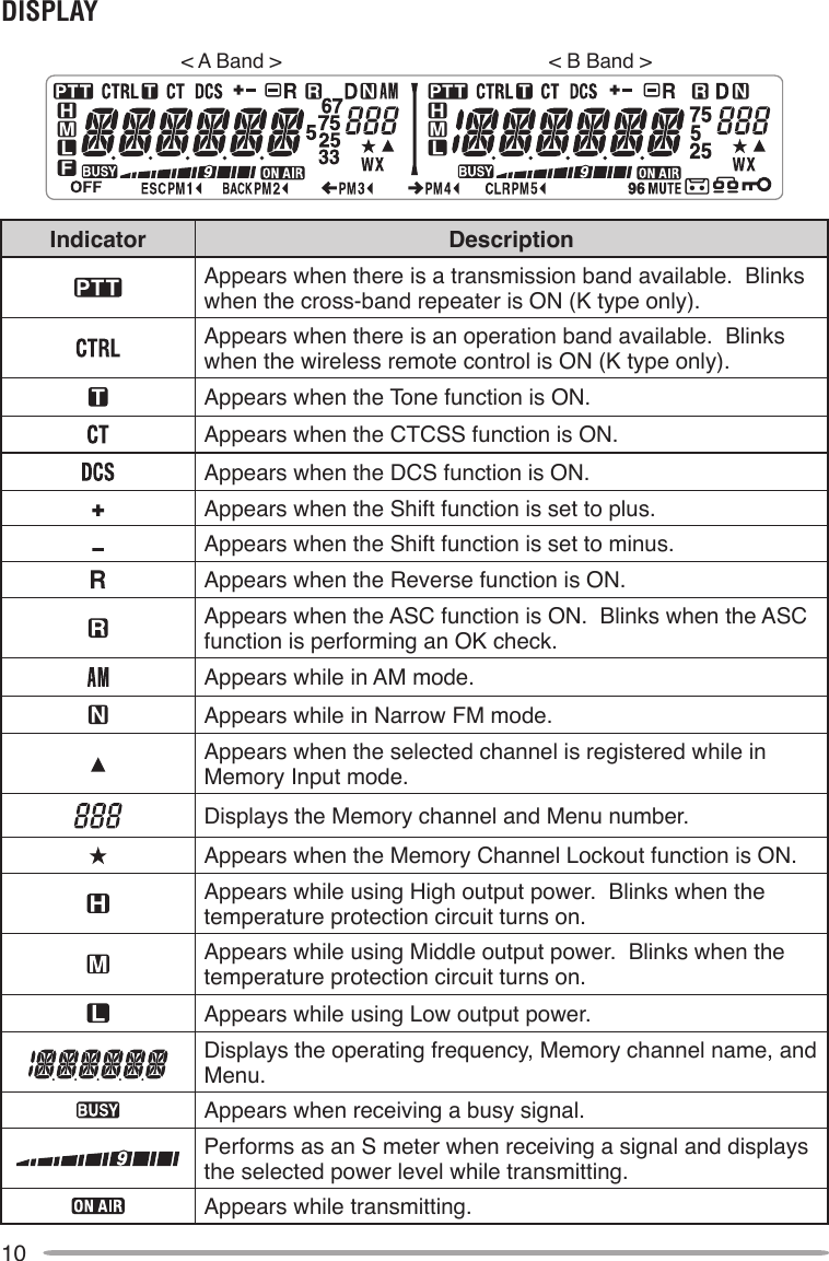
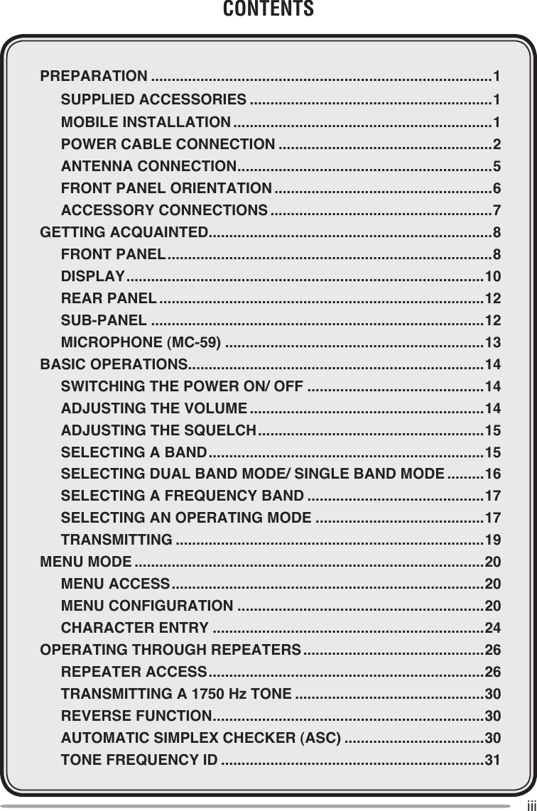
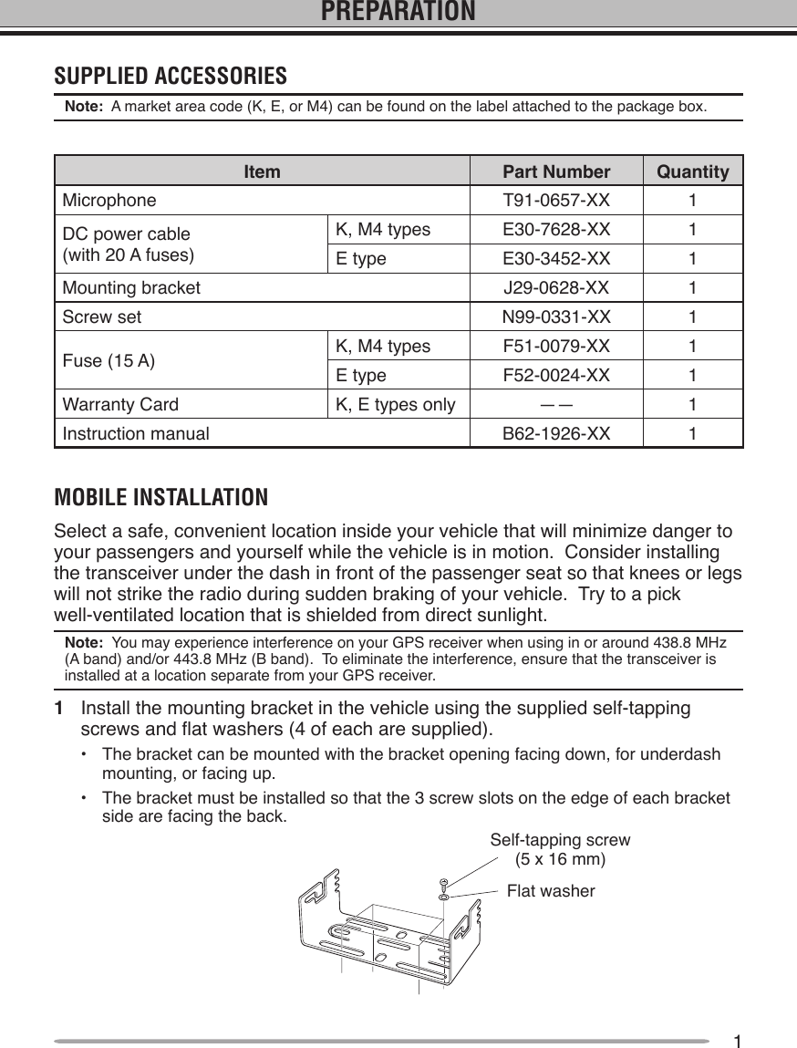
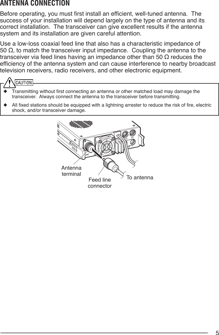
![13Keypad serial dataNo ConnectionMIC, 600 Ω impedanceGND (MIC)PTTGNDDC 8 V, 100 mA maxNo ConnectionMicrophone (Mc-59)q PTT switch Press and hold, then speak into the microphone to transmit.w DTMF keypad Press these keys to make DTMF calls, enter frequencies, or enter characters.e CALL/ A Functions the same as the transceiver front panel [CALL] key. This is also the PF4 key and can be reprogrammed with a programmable function {page 66}.r VFO/ B Functions the same as the transceiver front panel [VFO] key. This is also the PF3 key and can be reprogrammed with a programmable function {page 66}.t MR/ C Functions the same as the transceiver front panel [MR] key. This is also the PF2 key and can be reprogrammed with a programmable function {page 66}.y PF/ D Press to toggle between bands A and B. This is also the PF1 key and can be reprogrammed with a programmable function {page 66}.u UP/ DWN Functions the same as the transceiver Tuning control.Microphone Jack](https://usermanual.wiki/JVC-KENWOOD/397700.Instruction-Manual-1/User-Guide-768505-Page-21.png)
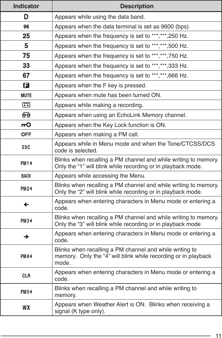
![14BASIC OPERATIONSSWITCHING THE POWER ON/ OFFPress the switch to switch the transceiver ON.• The power on message momentarily appears on the display.• Ifthetransceiverpasswordprotectionhasbeenactivated{page74},youmustrstenteryour password before you can operate the transceiver. Press the switch again to switch the transceiver OFF.ADJUSTING THE VOLUMERotate the [BAND SEL] (VOL) control of your selected band clockwise to increase the volume and counterclockwise to decrease the volume.Note: Some functions of this transceiver, such as the beep and voice announcements, have their own volume settings. Adjust those settings to your desired values.](https://usermanual.wiki/JVC-KENWOOD/397700.Instruction-Manual-1/User-Guide-768505-Page-22.png)
![15ADJUSTING THE SQUELCHSquelch is used to mute the speaker when no signals are present. With the squelch level set correctly, you will hear sound only while actually receiving a signal. The higher the squelch level selected, the stronger the signals must be in order to hear them.Rotate the [SQL] control of your selected band, when no signals are present, and select the squelch level at which the background noise is just eliminated.SELECTING A BANDPress the left [BAND SEL] control to select band A and the right [BAND SEL] control to select band B.• The icon appears at the top of the band on which you are operating and the icon appears at the top of the band on which you are currently set to transmit. Band A (left [BAND SEL] control): Band B (right [BAND SEL] control):](https://usermanual.wiki/JVC-KENWOOD/397700.Instruction-Manual-1/User-Guide-768505-Page-23.png)
![16Pressing [PF2] allows you to switch the operating band between bands A and B, while maintaining the original band as the transmit band. Band A is the transmit band and band B is the operating band: Band A is both the transmit and operating band:SELECTING DUAL BAND MODE/ SINGLE BAND MODEYou can switch the transceiver between dual band operation and single band operation by pressing [BAND SEL] (1s) of your selected band. Dual band mode: Single band mode (band A only):(In Single band mode, you can turn the center partion bar display off {page 72}.)](https://usermanual.wiki/JVC-KENWOOD/397700.Instruction-Manual-1/User-Guide-768505-Page-24.png)
![17SELECTING A FREQUENCY BANDYou can change the default frequency bands for bands A and B.1 Select band A or B by pressing the [BAND SEL] control or [PF2].2 Press [F], [BAND SEL] of your selected band.• Each time you press [F], [BAND SEL], you cycle to the next frequency band.• The default setting of the [PF1] key also allows you to cycle to the next frequency band.• When masking a band {page 71}, you are restricted to using only the selectable band.• When receiving 2 signals on the same band, the image interference, senstivity, etc., performance will decrease.• Band A: 118 >> 144 (default) >> 220 >> 300 >> 430/440 (MHz).• Band B: 144 >> 220 >> 430/440 (default) >> 12000 (MHz).Note:u M4 type models do not have the following frequency bands available: 118, 220, 300, or 12000 (MHz).u E and M4 type models use the 430 MHz band and K type models use the 440 MHz band. SELECTING AN OPERATING MODEThere are 3 operating modes available to choose from: VFO mode, Memory Channel mode, and Call Channel mode.■ VFO Mode VFO mode allows you to manually change the operating frequency.1 Press [VFO] to enter VFO mode.](https://usermanual.wiki/JVC-KENWOOD/397700.Instruction-Manual-1/User-Guide-768505-Page-25.png)
![182 Rotate the Tuning control to select your desired operating frequency.• You can also adjust the frequency by using the microphone [UP]/[DWN] keys.• The default step frequency for the Tuning control varies according to the type and operating band:Type 144 MHz 430/440 MHzK 5 kHz 25 kHzE 12.5 kHz 25 kHzM4 10 kHz 10 kHz• To adjust the frequency by a larger amount, you can press the Tuning control to enter MHz mode. While in MHz mode, rotate the Tuning control to adjust the frequency in steps of 1 MHz. Press the Tuning control again to exit MHz mode and adjust the frequency using the normal step frequency.■ Memory Channel Mode Memory Channel mode allows you to quickly select a frequently used frequency and related data which you have saved in the transceiver memory.1 Press [MR] to enter Memory Channel mode.2 Rotate the Tuning control to select your desired Memory channel.](https://usermanual.wiki/JVC-KENWOOD/397700.Instruction-Manual-1/User-Guide-768505-Page-26.png)
![19■ Call Channel Mode Call Channel mode allows you to quickly select a preset channel to allow immediate calls on that frequency. The Call channel can be conveniently used as an emergency channel within your group.1 Select your desired band (A or B).• The Call channel has a dedicated frequency for both bands A and B. The default frequency for band A is 144 MHz. The default frequency for band B is 430/440 MHz. 2 Press [CALL] to enter Call Channel mode.• The C icon appears on the display.3 Press [CALL] again to return to your previous operating frequency.TRANSMITTING1 Select your desired band and frequency/channel.2 Press and hold the microphone [PTT] switch and speak into the microphone to transmit.• The icon and the RF power meter appear on the display for the selected transmit band. The RF power meter shows the relative transmit output power.• The / / icon(s) appear on the display, depending on what output power you have selected {page 70}.• Speak into the microphone in your normal voice, while keeping the microphone approximately 5 cm from your mouth. Speaking too close to the microphone or too loudly may increase distortion and reduce intelligibility of your signal at the receiving station.3 Whenyounishspeaking,releasethe[PTT] switch.](https://usermanual.wiki/JVC-KENWOOD/397700.Instruction-Manual-1/User-Guide-768505-Page-27.png)
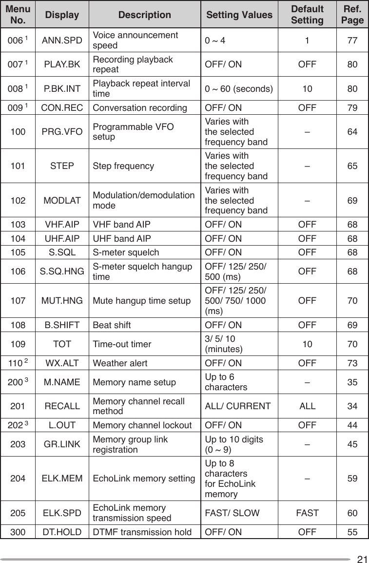
![20MENU MODEMany functions on this transceiver are selected or congured through the Menu instead of physical controls. Once you become familiar with the Menu system, you will appreciate the versatility it offers.MENU ACCESS1 Press [F], Tuning control to access the Menu.• The Menu name and number appears on the display.2 Rotate the Tuning control to select your desired Menu.3 Press the Tuning control to set up the current Menu.4 Rotate the Tuning control to select your desired value for the selected Menu.5 Press the Tuning control to set the selected value.6 Repeat steps 2 to 5 to set up additional Menus.• Press [CALL] (ESC) at any time to exit Menu mode.• Press [F] (BACK) at any time to cancel the Menu setup and return to the Menu selection.MENU CONFIGURATIONMenu No. Display Description Setting Values Default SettingRef. Page000 BEEP Beep sound OFF/ ON ON 64001 BP.VOL Beep volume level 1 ~ 7 5 64002 EXT.SP External speaker output modeMODE 1/ MODE 2 MODE 1 71003 1 ANN Voice announcement modeOFF/ AUTO/ MANUAL AUTO 75004 1 ANN.LNG Voice announcement language ENG/ JPN ENG 77005 1 ANN.VOL Voice announcement volume 1 ~ 7 5 77](https://usermanual.wiki/JVC-KENWOOD/397700.Instruction-Manual-1/User-Guide-768505-Page-28.png)
![24CHARACTER ENTRYCertain menus require you to enter characters, such as the power on message and memory names. When character entry is required, a cursor will appear on the display.1 Press the Tuning control.• The cursor will blink.2 Rotate the Tuning control to select your desired character.• You can enter characters as described below:- Power on message, memory name, DTMF memory name, and repeater ID (K type only): 0 ~ 9, A ~ Z, -, /, @, and space- EchoLink memory: 0 ~ 9, A ~ Z, and space- DTMF memory: 0 ~ 9, A ~ F, and space- Memory group link and wireless remote ID (K type only): 0 ~ 93 Press the Tuning control to set the selected character.• The cursor will move to the next digit.• You can move the cursor to the left or right by pressing [REV] ( ) or [LOW] ( ).• You can delete the selected character by pressing [PF1] (CLR). 4 Repeat steps 2 and 3 to enter the remaining characters.• Press [CALL] (ESC) at any time to exit Menu mode.• Press [TONE] (BACK) at any time to cancel the Menu setup and return to the Menu selection.](https://usermanual.wiki/JVC-KENWOOD/397700.Instruction-Manual-1/User-Guide-768505-Page-32.png)
![25n Microphone Keypad Character Entry The microphone keys can also be used to enter characters. Refer to the table below for characters corresponding to microphone keys.Key Character Display (with each press of the key)1 Q Z 12 A B C 23 D E F 34 G H I 45 J K L 56 M N O 67 P R S 78 T U V 89 W X Y 90 (space) 0Not used# – / @ The microphone [A] ~ [D] keys have special functions assigned to them: [A]: Functions the same as [PF1] (CLR) [B]: Functions the same as [REV] ( ) [C]: Functions the same as [LOW] ( ) [D]: Functions the same as the Tuning control](https://usermanual.wiki/JVC-KENWOOD/397700.Instruction-Manual-1/User-Guide-768505-Page-33.png)
![26OPERATING THROUGH REPEATERSRepeaters are often installed and maintained by radio clubs, sometimes with the cooperation of local businesses involved in the communications industry.Compared to simplex communication, you can usually transmit over much greater distances by using a repeater. Repeaters are typically located on mountain tops or other elevated locations. They generally operate at higher ERP (Effective Radiated Power) than a typical station. This combination of elevation and high ERP allows communications over considerable distances.REPEATER ACCESSMost repeaters use a receive and transmit frequency pair with a standard or non-standard offset (odd-split). In addition, some repeaters must receive a tone from the transceiver in order to gain access to the repeater. For details, consult your local repeater reference.n Selecting an Offset Direction The offset direction allows your transmit frequency to be higher (+) or lower (–) than the receive frequency.1 Select your desired band (A or B).2 Press [F], [REV] (1s) to select an offset direction.• Each time you press [F], [REV] (1s), the offset direction changes as follows: Simplex operation >> + >> – >> Simplex operationTX: 144.725 MHzTX tone: 88.5 HzRX: 145.325 MHz TX: 144.725 MHzTX tone: 88.5 HzRX: 145.325 MHz](https://usermanual.wiki/JVC-KENWOOD/397700.Instruction-Manual-1/User-Guide-768505-Page-34.png)
![27• If you are using an E-market transceiver, when operating on the 430 MHz band, the offset direction changes as follows: Simplex operation >> + >> – >> = (–7.6 MHz) >> Simplex operation If the offset transmit frequency falls outside the allowable range, transmitting is inhibited. Use one of the following methods to bring the transmit frequency within the band limits:• Move the receive frequency further inside the band.• Change the offset direction.Note: While using an odd-split memory channel or transmitting, you cannot change the offset direction.n Selecting an Offset Frequency The offset frequency is the value which the transmit frequency will be offset from the receive frequency. The default offset frequency on the 144 MHz band is 600 kHz for all market versions. The default on the 430/440 MHz band is 5 MHz.1 Select your desired band (A or B).2 Enter Menu mode and access Menu 400 (OFFSET) {page 20}.3 Set the appropriate offset frequency value.• The selectable range is from 00.00 MHz to 29.95 MHz, in steps of 50 kHz.Note: After changing the offset frequency, the new offset frequency will also be used by Automatic Repeater Offset {page 29}.n Activating the Tone Function To turn the Tone function on:1 Select your desired band (A or B).2 Press [TONE] to turn the Tone function ON.• Each time you press [TONE], the selection changes as follows: None >> T (Tone) >> CT (CTCSS) >> DCS (DCS) >> NoneNote: When accessing a repeater that requires a 1750 Hz tone, you do not need to activate the Tone function. Simply press the key assigned to the 1750 Hz tone {page 66} to transmit the tone.](https://usermanual.wiki/JVC-KENWOOD/397700.Instruction-Manual-1/User-Guide-768505-Page-35.png)
![28n Selecting a Tone Frequency To select the tone frequency required to access your desired repeater:1 Turn the Tone function ON.2 Press [F], [TONE].• The current tone frequency appears on the display. The default frequency is 88.5 Hz.3 Rotate the Tuning control to select your desired frequency.• To exit the tone frequency selection, press [F] (ESC).4 Press any key other than the Tuning control and [F] (ESC) to set the selected frequency.Note: If you have set up a Memory channel with a tone setting, simply recall the Memory channel instead of setting up the tone frequency every time.No. Frequency (Hz) No. Frequency (Hz) No. Frequency (Hz) No. Frequency (Hz)01 67.0 12 97.4 23 141.3 34 206.502 69.3 13 100.0 24 146.2 35 210.703 71.9 14 103.5 25 151.4 36 218.104 74.4 15 107.2 26 156.7 37 225.705 77.0 16 110.9 27 162.2 38 229.106 79.7 17 114.8 28 167.9 39 233.607 82.5 18 118.8 29 173.8 40 241.808 85.4 19 123.0 30 179.9 41 250.309 88.5 20 127.3 31 186.2 42 254.110 91.5 21 131.8 32 192.811 94.8 22 136.5 33 203.5](https://usermanual.wiki/JVC-KENWOOD/397700.Instruction-Manual-1/User-Guide-768505-Page-36.png)
![29n Automatic Repeater Offset (K and E Types Only) This function automatically selects an offset direction and activates the Tone function, according to the frequency that you have selected. To obtain an up-to-date band plan for repeater offset direction, contact your national Amateur Radio association.1 Enter Menu mode and access Menu 401 (ARO) {page 20}.2 Set the ARO to ON.3 Press [BAND SEL A] to select the A band.4 Press [VFO] to select VFO mode.5 Rotate the Tuning control to select your desired frequency.6 Press [PTT] to start a call.• You will be transmitting on an offset frequency value determined from your offset setting value {page 27} and an offset direction depending on your selected frequency. Refer to the settings below for offset directions: K Market: Under 145.100 MHz: No offset (Simplex operation) 145.100 ~ 145.499 MHz: Minus (–) offset 145.500 ~ 145.599 MHz: No offset (Simplex operation) 146.000 ~ 146.399 MHz: Plus (+) offset 146.400 ~ 146.599 MHz: No offset (Simplex operation) 146.600 ~ 146.999 MHz: Minus (–) offset 147.000 ~ 147.399 MHz: Plus (+) offset 147.400 ~ 147.599 MHz: No offset (Simplex operation) 147.600 ~ 147.999 MHz: Minus (–) offset 148.000 MHz and higher: No offset (Simplex operation) E Market: Under 145.000 MHz: No offset (Simplex operation) 145.600 ~ 145.799 MHz: Minus (–) offset 145.800 MHz and higher: No offset (Simplex operation)](https://usermanual.wiki/JVC-KENWOOD/397700.Instruction-Manual-1/User-Guide-768505-Page-37.png)
![30TRANSMITTING A 1750 Hz TONEMost repeaters in Europe require that a transceiver transmit a 1750 Hz tone. By turning the 1750 Hz tone menu item ON, the transceiver will automatically transmit the 1750 Hz tone for 2 seconds whenever you transmit.1 Enter Menu mode and access Menu 402 (1750HD) {page 20}.2 Set the tone to ON or OFF.• When set to ON, the 1750 Hz tone will transmit. When set to OFF, the tone will not be transmitted.REVERSE FUNCTIONAfter setting a separate receive and transmit frequency, you can exchange these frequencies using the Reverse function. This allows you to manually check the strength of signals you receive directly from other stations, while using a repeater. If the station’s signal is strong, move to a simplex frequency to continue the contact and free up the repeater.Press [REV] to turn the Reverse function ON or OFF.• When the Reverse function is ON, the icon will appear on the display.Note:u If the transmit frequency is outside the allowable transmit frequency range when using Reverse, pressing [PTT] will cause an error tone to sound and transmission will be inhibited.u If the receive frequency is outside the receive frequency range when using Reverse, an error tone will sound and Reverse will not operate.u The ARO (Automatic Repeater Offset) will not function when Reverse is ON.u You cannot switch Reverse ON or OFF while transmitting.AUTOMATIC SIMPLEX CHECKER (ASC)While using a repeater, ASC periodically monitors the strength of signals you receive directly from the other stations. If the station’s signal is strong enough to allow direct contact without a repeater, the icon blinks.Press [REV] (1s) to turn the ASC ON.](https://usermanual.wiki/JVC-KENWOOD/397700.Instruction-Manual-1/User-Guide-768505-Page-38.png)
![31• When the ASC is ON, the icon will appear on the display.• While direct contact is possible, without the use of a repeater, the icon will begin blinking.• To exit ASC, press [REV]. Note:u Pressing [PTT] will cause the icon to stop blinking.u ASC does not function if you are using simplex operation.u ASC does not function while scanning.u Activating ASC while using Reverse will switch the Reverse function OFF.u If you recall a Memory channel or the Call channel, and those channels are set up with the Reverse function switched ON, the ASC will switch OFF.u ASC causes received signals to be momentarily intermitted every 3 seconds.TONE FREQUENCY IDThis function scans through all tone frequencies to identify the incoming tone frequency on a received signal. You can use this function to nd which tone frequency is required by your local repeater.1 Press [TONE] to switch the Tone function ON.• The icon appears on the display.2 Press [F], [TONE] (1s) to run the Tone Frequency ID scan.• The icon blinks and SCAN appears on the display.• To reverse the scan direction, turn the Tuning control clockwise (upward scan) or counterclockwise (downward scan).• To quit the function, press [F] (ESC).• When the tone frequency is identied, the identied frequency appears on the display and blinks. Press any key other than the Tuning control while the identied frequency is blinking, to resume scanning.3 Press the Tuning control to program the identied frequency in place of the currently set tone frequency.• The Tone function will remain ON. You can press [TONE] to switch the Tone function OFF.• Press [F] (ESC) if you do not want to program the identied frequency.](https://usermanual.wiki/JVC-KENWOOD/397700.Instruction-Manual-1/User-Guide-768505-Page-39.png)
![33STORINg SIMPLEX AND STANDARD REPEATER FREquENCIES1 Press [VFO] to enter VFO mode.2 Rotate the Tuning control to select your desired frequency.• Additionally, you can press the microphone [UP]/[DWN] keys to select a frequency.3 Set up any additional data desired for the frequency.• Offset direction, Tone ON/OFF, Tone frequency, CTCSS ON/OFF, CTCSS frequency, DCS ON/OFF, DCS code, etc.4 Press [F].• A memory channel number appears.5 Rotate the Tuning control to select your desired channel number.• Additionally, you can press the microphone [UP]/[DWN] keys to select a channel.6 Press [MR] to store the data in the selected Memory channel.Note: If you store the data in a Memory channel that already has data stored in it, the old data will be cleared and the new data will be stored.n Call Channel Memory (Simplex) The Call channel can be used to store any frequency and related data that you will recall often. You may want to dedicate the Call channel as an emergency channel within your group. To store a simplex frequency and related data as the Call channel instead of in a Memory channel, after step 4 (above), press [CALL].Note: Storing new data in the Call channel will clear the old data. (The Call channel itself cannot be cleared, but data can be replaced with new data.)STORINg ODD-SPLIT REPEATER FREquENCIESSome repeaters use a receive and transmit frequency pair with a non-standard offset. To access those repeaters, store two separate frequencies in a memory channel. You can then operate on those repeaters without changing the offset frequency you stored in the menu.1 Set up a simplex channel by following steps 1 to 6 of “STORING SIMPLEX AND STANDARD REPEATER FREQUENCIES”, above.2 Press [VFO] to enter VFO mode.3 Rotate the Tuning control to select your desired transmit frequency.• Additionally, you can press the microphone [UP]/[DWN] keys to select a frequency.](https://usermanual.wiki/JVC-KENWOOD/397700.Instruction-Manual-1/User-Guide-768505-Page-41.png)
![344 Set up any additional data desired for the transmit frequency.• Tone ON/OFF, Tone frequency, CTCSS ON/OFF, CTCSS frequency, DCS ON/OFF, DCS code, etc.5 Press [F].• A memory channel number appears.6 Rotate the Tuning control to select your desired channel number.• Additionally, you can press the microphone [UP]/[DWN] keys to select a channel.7 Press [PTT], [MR] to store the data in the selected Memory channel.n Call Channel Memory (Odd-Split) The Call channel can be used to store any frequency and related data that you will recall often. You may want to dedicate the Call channel as an emergency channel within your group. To store an odd-split frequency and related data as the Call channel instead of in a Memory channel, after step 6 (above), press [PTT], [CALL].Note: You cannot store the transmit offset status and Reverse status in an odd-split Call channel.RECALLINg A MEMORY CHANNEL1 Press [MR] to enter Memory Recall mode.2 Rotate the Tuning control to select your desired Memory channel.• Additionally, you can press the microphone [UP]/[DWN] keys to select a channel, or you can enter a channel number using the microphone keypad.The transceiver Menu also provides you with the option to recall Memory channels with storedfrequencies in your current band, or all Memory channels:1 Enter Menu mode and access Menu 201 (RECALL) {page 20}.2 Set the recall method to CURENT (current band) or ALL (all bands).• CURENT allows you to recall only those memory channels that have stored frequencies within the current band. ALL allows you to recall all programmed memory channels (such as recalling a 144 MHz frequency channel when operating in the 430/440 MHz band).](https://usermanual.wiki/JVC-KENWOOD/397700.Instruction-Manual-1/User-Guide-768505-Page-42.png)
![35CLEARINg A MEMORY CHANNEL1 Press [MR] to enter Memory Recall mode.2 Rotate the Tuning control to select your desired Memory channel.• Additionally, you can press the microphone [UP]/[DWN] keys to select a channel, or you can enter a channel number using the microphone keypad.3 Turn the transceiver power OFF.4 Press [MR] + Power ON.• Aconrmationmessageappearsonthedisplay.5 Press the Tuning control to clear the Memory channel.• To exit without clearing the channel, press [F] (ESC).NAMINg A MEMORY CHANNELYou can name Memory channels using up to 6 alphanumeric characters. When you recall a named Memory channel, its name appears on the display instead of the stored frequency. Names can be call signs, repeater names, cities, people, etc.1 Press [MR] to enter Memory Recall mode.2 Rotate the Tuning control to select your desired Memory channel.3 Enter Menu mode and access Menu 200 (MNAME) {page 20}.4 Enter your desired name for the channel {page 24}.Note: You can overwrite a Memory channel name by performing the steps above. You can also clear a Memory channel name by clearing the Memory channel.](https://usermanual.wiki/JVC-KENWOOD/397700.Instruction-Manual-1/User-Guide-768505-Page-43.png)
![36SwITCHINg THE MEMORY NAME/ FREquENCY DISPLAYAfter storing memory names, you can switch the display between the memory nameandthestoredfrequency.Thiscanbeusefulifyouneedtoconrmthefrequency stored in named Memory channels.1 Press [MR] to enter Memory Recall mode.2 Press the Tuning control to toggle between the memory name and the stored frequency. <—> MEMORY-TO-VFO TRANSFERTransferring the contents of a Memory channel or the Call channel to the VFO can be useful if you want to search for other stations or a clear frequency, near the selected Memory channel or Call channel frequency.1 Press [MR] or [CALL] to enter Memory Recall mode or select the Call channel.2 Rotate the Tuning control to select your desired channel. (This step is not necessary when selecting the Call channel.)3 Press [F], [VFO].• The entire contents of the Memory channel or Call channel are copied to the VFO, and VFO mode is selected after the transfer is complete.• When copying a transmit frequency from an odd-split Memory or Call channel, you mustrstturntheReversefunctionONbeforepressing[F], [VFO].CHANNEL DISPLAY FuNCTIONWhen this function is switched ON, the transceiver displays only a Memory channel number instead of a frequency.1 Turn the transceiver power OFF.2 Press [LOW] + Power ON to turn the channel display ON or OFF. <—> Note:u If no Memory channels have saved data in them, channel display will not function.u If a channel has a stored name, the name will appear on the display in place of the channel number.u When using Channel Display, you cannot reset the transceiver.](https://usermanual.wiki/JVC-KENWOOD/397700.Instruction-Manual-1/User-Guide-768505-Page-44.png)
![37 While in Channel Display mode, the transceiver keys function as shown below:Key Name [KEY] [F], [KEY] [KEY] (1s) While Transmitting[KEY] + Power ONPower ON/OFFPower ON/OFFPower ON/OFFPower ON/OFFPower ON/OFFPM PM Recall PM In – – –VFO VFO mode Memory to VFO copy VFO Scan – –MR MR modeStore in Memory channelMemory Scan –Memory ClearCALL Call mode Store in Call channel Call Scan – –FFunction modeExit Function mode Key Lock – ResetTONETone/ CTCSS/ DCSTone/CTCSS/DCS freq./code selection– –Repeater/Cross/A-TX/B-TX/OFFREV Reverse ON/OFFShift ON/OFFASC ON/OFF – –LOW Change output power Mute – Change output powerChange channel displayPF1E/M4: Change frequency bandK: Select the Weather channel––––PF2 Change control band –––Turn EchoLink ON/OFFTuning controlChange between the freq. and CH nameMenu mode MHz Scan/ Group Scan – –BAND SEL AA band Change the freq. bandChange Single/Dual –Band Mask ABAND SEL BB band Change the freq. bandChange Single/Dual –Band Mask B](https://usermanual.wiki/JVC-KENWOOD/397700.Instruction-Manual-1/User-Guide-768505-Page-45.png)
![40stORInG DAtA In PM chAnnELs1 Conrm that the following conditions have been satised:• The transceiver is in receive mode.• Scan is not being used.• Microphone Control is OFF.2 Congure the transceiver with your desired settings.• For data that can be stored, refer to page 38.3 Press [F], [PM].• PM channel numbers 1 to 5 appear and blink at the bottom of the display.4 Enter a channel number ([1] to [5]) corresponding to your desired PM channel.• The settings are stored in the PM channel.REcALLInG PM chAnnELs1 Press [PM].• PM channel numbers 1 to 5 appear on the bottom of the display.2 Enter a channel number ([1] to [5]) corresponding to your desired PM channel.• The settings stored in the PM channel are recalled.• The selected channel number appears on the display.](https://usermanual.wiki/JVC-KENWOOD/397700.Instruction-Manual-1/User-Guide-768505-Page-48.png)
![41AutO PM chAnnEL stOREAfter you recall a PM channel, this function automatically overwrites the current PM channel with the present operating environment when:• You recall another PM channel.• You press [PM].• You switch the transceiver power OFF.Follow the steps below to activate the Auto PM storage function.1 Enter Menu mode and access Menu 521 (AUTOPM) {page 20}.2 Set AUTOPM to ON.PM chAnnEL REsEtTo reset the PM channels to their default settings:1 Turn the transceiver power OFF.2 Press [F] + Power ON.3 Release [F].4 Rotate the Tuning control and select PM.5 Press the Tuning control.• A conrmation message appears on the display.6 Press the Tuning control again to reset the PM channels.• Press [TONE] (BACK) to return to the previous display.• To exit without resetting the PM channels, press [F] (ESC).](https://usermanual.wiki/JVC-KENWOOD/397700.Instruction-Manual-1/User-Guide-768505-Page-49.png)
![42SCANScan is a useful feature for hands-off monitoring of your favorite frequencies. Becoming comfortable with all types of Scan will increase your operating efciency.This transceiver provides the following types of scans:Scan Type Scan RangeVFO Scan Scans all frequencies on the current band.Memory Scan Scans all frequencies stored in the Memory channels.Group Scan Scans the frequencies in the Memory channels which belong to the group you have specied.Program Scan Scans all frequencies within the programmed range, on the current band.MHz Scan Scans all frequencies within a 1 MHz range from the originating frequency.Call Scan Scans the Call channel as well as the currently selected VFO frequency or Memory channel.Note:u Adjust the squelch level before using Scan. Selecting a squelch level too low could cause Scan to stop immediately.u While using CTCSS or DCS, Scan stops for any signal received; however, you will hear audio only when the signal contains the same CTCSS tone or DCS code that you selected.u When using S-meter Squelch, Scan stops when the received signal strength matches or exceeds the S-meter setting. Scan resumes 2 seconds after the signal level drops below the S-meter setting.u Pressing and holding [PTT] causes Scan to temporarily stop if it is functioning on a non TX band.u Starting Scan switches the Automatic Simplex Checker OFF.](https://usermanual.wiki/JVC-KENWOOD/397700.Instruction-Manual-1/User-Guide-768505-Page-50.png)
![43SELECTING A SCAN RESUME METHODThe transceiver stops scanning at a frequency or Memory channel on which a signal is detected. It then continues scanning according to which resume mode you have selected. You can choose one of the following modes. The default is Time-operated mode.• Time-Operated mode The transceiver remains on a busy frequency or Memory channel for approximately 5 seconds, and then continues to scan even if the signal is still present.• Carrier-Operated mode The transceiver remains on a busy frequency or Memory channel until the signal drops out. There is a 2 second delay between signal drop-out and scan resumption.• Seek mode The transceiver remains on a busy frequency or Memory channel even after the signal drops out and does not automatically resume scanning.Note: To temporarily stop scanning and monitor weak signals, press the microphone PF key assigned to the Monitor function {page 66}. Press the PF key again to resume scanning.1 Enter Menu mode and access Menu 514 (SC.RESM) {page 20}.2 Set the Scan Resume mode to TO (Time-Operated), CO (Carrier-Operated) or SEEK.VFO SCANVFO Scan monitors all frequencies tunable on the band, using the current frequency step size.1 Select your desired band.2 Press [VFO] (1s).• Scan starts at the current frequency.• The 1 MHz decimal blinks while scanning is in progress.• To reverse the scan direction, turn the Tuning control clockwise (upward scan) or counterclockwise (downward scan). You can also press microphone [UP]/ [DWN].3 To quit VFO Scan, press [VFO] again.](https://usermanual.wiki/JVC-KENWOOD/397700.Instruction-Manual-1/User-Guide-768505-Page-51.png)
![44MEMORY SCANUse Memory Scan to monitor all Memory channels programmed with frequency data.1 Select your desired band.2 Press [MR] (1s).• Scan starts at the current frequency.• The 1 MHz decimal blinks while scanning is in progress.• To reverse the scan direction, turn the Tuning control clockwise (upward scan) or counterclockwise (downward scan). You can also press microphone [UP]/ [DWN].3 To quit Memory Scan, press [MR] again.Note:u At least 2 Memory channels must contain data and must not be locked out of scan.u The L0/U0 to L9/U9 Memory channels will not be scanned.u You can also start Memory Scan when in Channel Display mode. While Scan is paused on a channel, the channel number blinks.n Locking Out a Memory Channel You can select Memory channels that you prefer not to monitor while scanning.1 Press [MR], then rotate the Tuning control to select your desired channel.2 Enter Menu mode and access Menu 202 (L.OUT) {page 20}. 3 Set the lockout to ON to lock the channel out of the scanning sequence.• To cancel lockout, set the lockout to OFF.• The icon appears on the display for a channel that has been locked out.Note: The L0/U0 to L9/U9 Memory channels cannot be locked out.](https://usermanual.wiki/JVC-KENWOOD/397700.Instruction-Manual-1/User-Guide-768505-Page-52.png)
![45GROUP SCANFor the purpose of Group Scan, the 1000 Memory channels are divided into 10 groups, with each group containing 100 channels. Group Scan monitors only the 100 channels which belong to the specic group you are scanning. The channels are grouped as follows:Memory Group Channel Range Memory Group Channel Range0 0 ~ 99 5 500 ~ 5991 100 ~ 199 6 600 ~ 6992 200 ~ 299 7 700 ~ 7993 300 ~ 399 8 800 ~ 8994 400 ~ 499 9 900 ~ 9991 Press [MR], then rotate the Tuning control to select a channel in your desired group.2 Press [MHz] (1s).• Scan starts at the current channel.• The 1 MHz decimal blinks while scanning is in progress.• To reverse the scan direction, turn the Tuning control clockwise (upward scan) or counterclockwise (downward scan). You can also press microphone [UP]/ [DWN].3 To quit Group Scan, press [MHz] again. Note:u At least 2 Memory channels in the selected group must contain data and must not be locked out of scan.u You can also start Memory Scan when in Channel Display mode. While Scan is paused on a channel, the channel number blinks.n Memory Group Link Memory Group Link provides you with the ability to link 2 or more Memory channel groups together to act as a single group when scanning. You can link up to 6 separate groups together, or even add multiple instances of the same group to the group link, to ensure that one group is scanned more often than the other groups.1 Enter Menu mode and access Menu 203 (GR.LINK) {page 20}.2 Press the Tuning control.• The cursor will begin blinking.](https://usermanual.wiki/JVC-KENWOOD/397700.Instruction-Manual-1/User-Guide-768505-Page-53.png)
![463 Rotate the Tuning control to select a group to link.4 Press the Tuning control to set the group and move the cursor to the right.• Press [TONE] (<) to move the cursor back or [LOW] (>) to move the cursor to the right.5 Repeat steps 3 and 4 to link additional groups together.6 When you have entered your desired groups, press [LOW] (>) to move the cursor to the right, then press the Tuning control to complete the entry and exit Menu mode.• If you have entered the maximum of 6 groups, simply press the Tuning control to complete the entry and exit Menu mode.PROGRAM SCANProgram Scan is identical to VFO Scan except that you select a frequency range for the scan.n Setting Scan Limits You can store up to 10 scan ranges in Memory channels L0/U0 to L9/U9.1 Select your desired band.2 Press [VFO].3 Rotate the Tuning control to select your desired frequency for the lower limit.4 Press [F].• A memory channel number appears and blinks.5 Rotate the Tuning control to select a channel from L0 to L9.6 Press [MR] to set the channel number.• The lower limit is stored in the channel.7 Rotate the Tuning control to select your desired frequency for the lower limit.](https://usermanual.wiki/JVC-KENWOOD/397700.Instruction-Manual-1/User-Guide-768505-Page-54.png)
![478 Press [F].9 Rotate the Tuning control to select a matching channel number from U0 to U9.• For example, if you selecte channel L3 in step 5, select channel U3 here.10 Press [MR] to set the channel number.• The upper limit is stored in the channel.• To conrm the stored scan limits, press [MR], then select the L and U channels.Note:u The lower limit must be lower in frequency than the upper limit.u The lower and upper frequency step sizes must be equal.u The lower and upper limits must be selected on the same band.n Using Program Scan1 Select your desired band.2 Press [VFO].3 Rotate the Tuning control to select a frequency within your desired scan range.4 Press [VFO], (1s).• Scan starts at the current frequency.• The 1 MHz decimal blinks while scanning is in progress.• To reverse the scan direction, turn the Tuning control clockwise (upward scan) or counterclockwise (downward scan). You can also press microphone [UP]/ [DWN].5 To quit Program Scan, press [VFO] again.Note:u If the step size differs between the lower limit and upper limit, VFO scan will begin instead of Program Scan.u If the current VFO frequency is within more than one Program Scan range, the range stored in the smallest channel number is used.](https://usermanual.wiki/JVC-KENWOOD/397700.Instruction-Manual-1/User-Guide-768505-Page-55.png)
![48MHz SCANMHz Scan monitors a 1 MHz segment of the band, using the current frequency step size. The current 1 MHz digit determines the limits of the scan. For example, if the current frequency is 145.400 MHz, then the scan range would be from 145.000 MHz to 145.995 MHz (the exact upper limit depends on the current frequency step size).1 Select your desired band.2 Press [VFO].3 Rotate the Tuning control to select a frequency within your desired 1 MHz range.4 Press and hold the Tuning control for 1 second to start scanning.• Scan starts at the current frequency.• The 1 MHz decimal blinks while scanning is in progress.• To reverse the scan direction, turn the Tuning control clockwise (upward scan) or counterclockwise (downward scan). You can also press microphone [UP]/ [DWN].5 To quit MHz Scan, press the Tuning control again.CALL SCANUse Call Scan to monitor both the Call channel and either the currently selected VFO frequency or the currently selected Memory channel.1 Select your desired VFO frequency or Memory channel.2 Press [CALL] (1s) to start Call Scan.• The 1 MHz decimal blinks while scanning is in progress.• When scanning a Memory channel, the Call channel on the same band as the selected Memory channel is used for scan.3 To quit Call Scan, press [CALL] again.Note: The Memory channel selected is scanned even if it has been locked out of scan.](https://usermanual.wiki/JVC-KENWOOD/397700.Instruction-Manual-1/User-Guide-768505-Page-56.png)