JVC KENWOOD 397700 Scanning Receiver User Manual Instruction Manual 2
JVC KENWOOD Corporation Scanning Receiver Instruction Manual 2
Contents
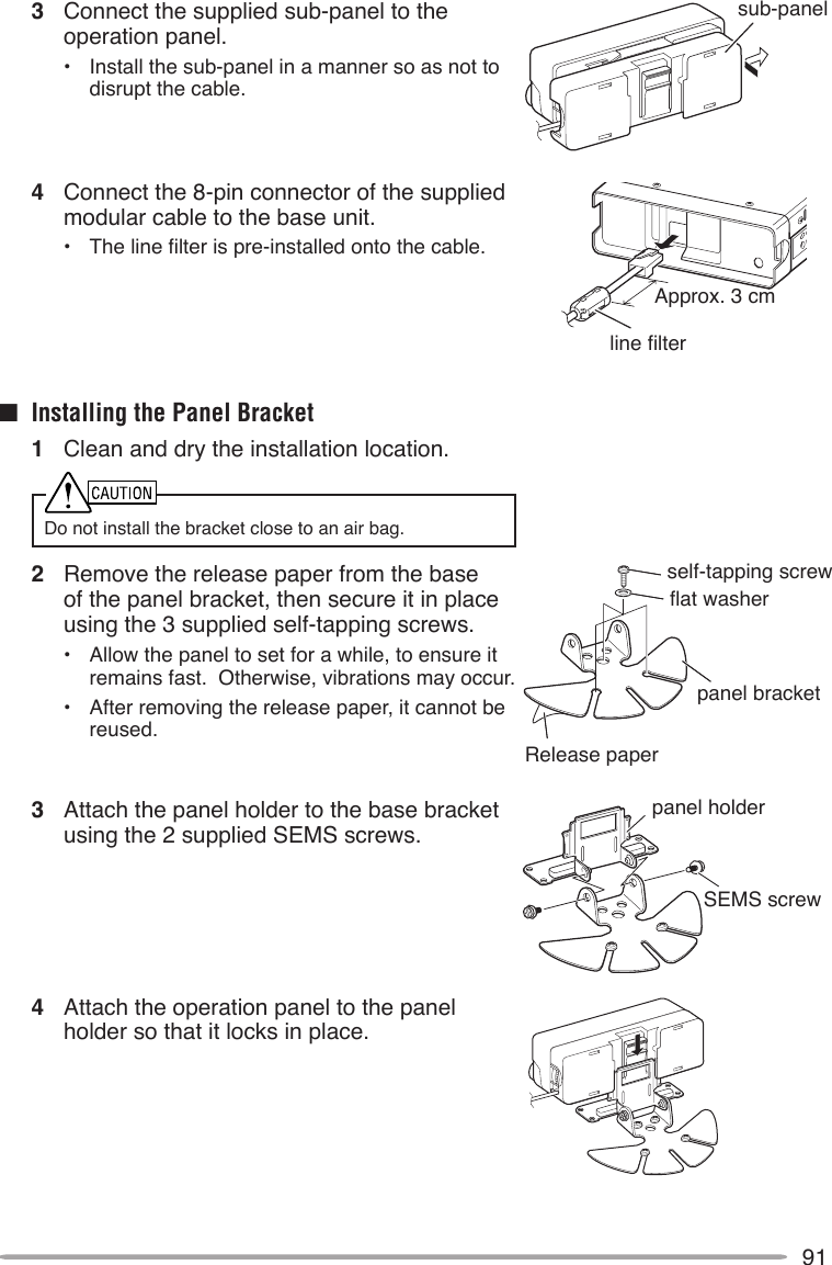
- 1. Instruction Manual 1
- 2. Instruction Manual 2
- 3. User Manual
- 4. User Instructions Guide
- 5. User Guide Instructions
Instruction Manual 2
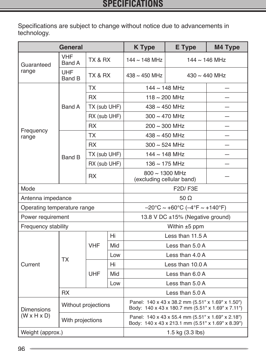
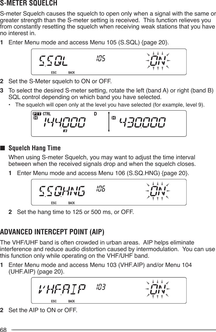
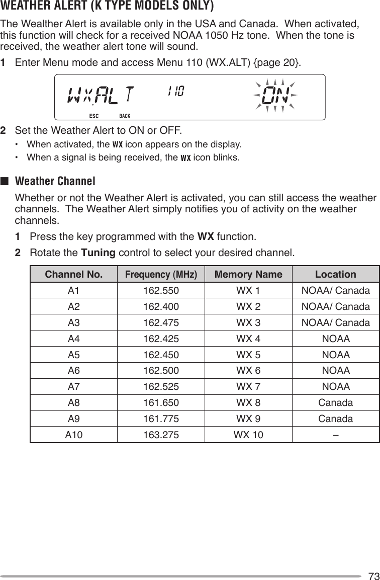
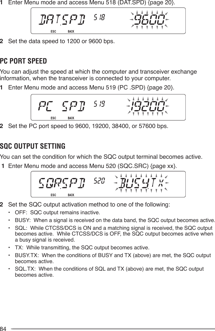
![49CONTINUOUS TONE CODED SQUELCH SYSTEM (CTCSS)You may sometimes want to hear calls only from specic persons. The Continuous Tone Coded Squelch System (CTCSS) allows you to ignore (not hear) unwanted calls from other persons who are using the same frequency. To do so, select the same CTCSS tone as selected by the other persons in your group. A CTCSS tone is subaudible and is selectable from among 42 standard tone frequencies.Note: CTCSS does not cause your conversation to be private. It only relieves you from listening to unwanted conversations.USING CTCSS1 Select your desired band.2 Press [TONE] 2 times to activate the CTCSS function.• The icon appears on the display when the CTCSS function is ON.• Each press of [TONE] changes the selection as follows: Tone (T) –> CTCSS (CT) –> DCS (DCS) –> Off (no display).3 Press [F], [TONE].• The current CTCSS frequency appears on the display and blinks.4 Rotate the Tuning control to select your desired CTCSS frequency.• Refer to the table below for the available frequencies.• To exit the CTCSS frequency selection, press [F] (ESC).5 Press any key other than the Tuning control and [F] (ESC) to complete the setting.6 When you are called: The transceiver squelch opens only when the selected CTCSS tone is received. When you make a call: Press and hold [PTT], then speak into the microphone.• To cancel CTCSS, press [TONE] until CT no longer appears on the display.](https://usermanual.wiki/JVC-KENWOOD/397700.Instruction-Manual-2/User-Guide-768506-Page-1.png)
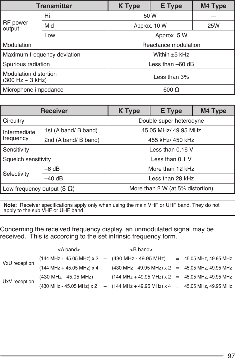
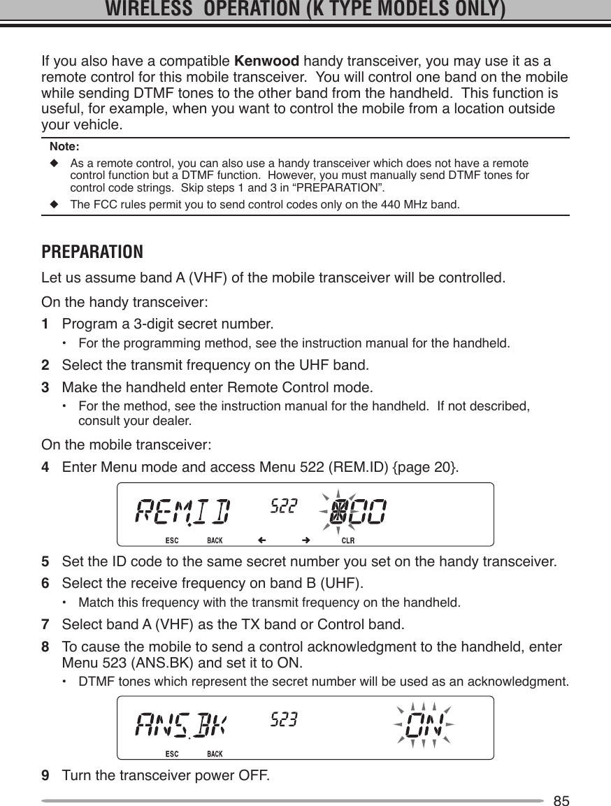
![50You can also select a CTCSS frequency by using the microphone:1 Select your desired band.2 Press [TONE] 2 times to activate the CTCSS function.• The icon appears on the display when the CTCSS function is ON.• Each press of [TONE] changes the selection as follows: Tone (T) –> CTCSS (CT) –> DCS (DCS) –> Off (no display).3 Press [F], [TONE].• The current CTCSS frequency appears on the display and blinks.4 Press the key programmed as [ENTER].5 Enter a frequency reference number (01 ~ 42) using the microphone keypad.• Refer to the table below for frequencies and their reference numbers.6 Press [ENTER] again to complete the setting.No. Frequency (Hz) No. Frequency (Hz) No. Frequency (Hz) No. Frequency (Hz)01 67.0 12 97.4 23 141.3 34 206.502 69.3 13 100.0 24 146.2 35 210.703 71.9 14 103.5 25 151.4 36 218.104 74.4 15 107.2 26 156.7 37 225.705 77.0 16 110.9 27 162.2 38 229.106 79.7 17 114.8 28 167.9 39 233.607 82.5 18 118.8 29 173.8 40 241.808 85.4 19 123.0 30 179.9 41 250.309 88.5 20 127.3 31 186.2 42 254.110 91.5 21 131.8 32 192.811 94.8 22 136.5 33 203.5](https://usermanual.wiki/JVC-KENWOOD/397700.Instruction-Manual-2/User-Guide-768506-Page-2.png)
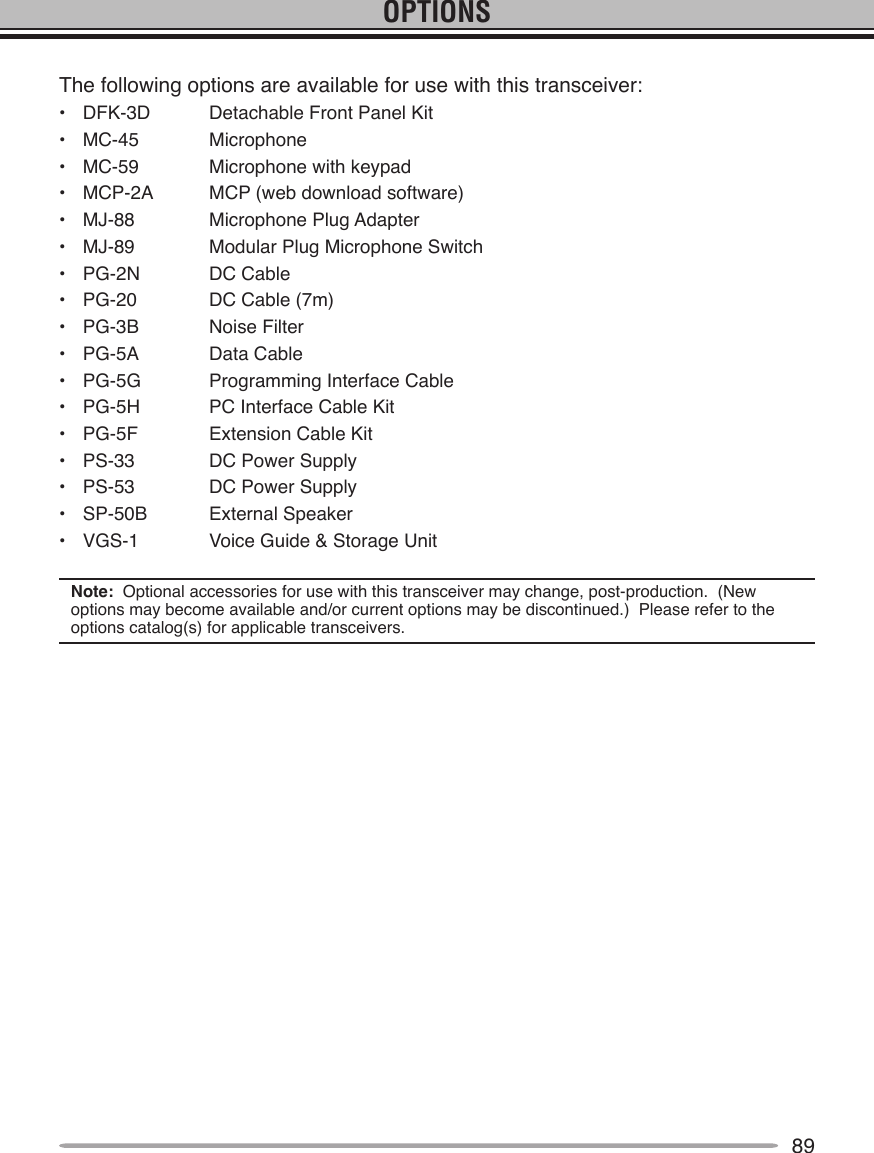
![51CTCSS FREQUENCY IDThis function scans through all CTCSS frequencies to identify the incoming CTCSS frequency on a received signal. You may nd this useful when you cannot recall the CTCSS frequency that the other persons in your group are using.1 Press [TONE] 2 times to activate the CTCSS function.• The icon appears on the display when the CTCSS function is ON.• Each press of [TONE] changes the selection as follows: Tone (T) –> CTCSS (CT) –> DCS (DCS) –> Off (no display).2 Press [F], [TONE] (1s).• The icon blinks and “SCAN” appears on the display.• Scan starts when a signal is received.• To reverse the scan direction, turn the Tuning control clockwise (upward scan) or counterclockwise (downward scan). You can also press microphone [UP]/ [DWN].• To quit the scan, press [F] (ESC).• When a CTCSS frequency is identied, the identied frequency appears on the display and blinks.3 Press the Tuning control to program the identied frequency in place of the currently set CTCSS frequency.• The CTCSS function will remain ON. To cancel CTCSS, press [TONE] until CT no longer appears on the display.• Press [F] (ESC) if you do not want to program the identied frequency. • Rotate the Tuning control while an identied frequency is blinking, to resume scanning.](https://usermanual.wiki/JVC-KENWOOD/397700.Instruction-Manual-2/User-Guide-768506-Page-3.png)
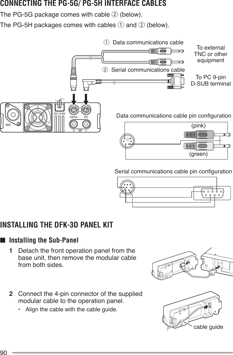
![52DIGITAL CODED SQUELCH (DCS)Digital Code Squelch (DCS) is another application which allows you to ignore (not hear) unwanted calls. It functions the same way as CTCSS. The only differences are the encode/ decode method and the number of selectable codes. For DCS, you can select from 104 different codes.USING DCS1 Select your desired band.2 Press [TONE] 3 times to activate the DCS function.• The icon appears on the display when the DCS function is ON.• Each press of [TONE] changes the selection as follows: Tone (T) –> CTCSS (CT) –> DCS (DCS) –> Off (no display).3 Press [F], [TONE].• The current DCS code appears on the display and blinks.4 Rotate the Tuning control to select your desired DCS code.• Refer to the table below for the available codes.• To exit the DCS code selection, press [F] (ESC).5 Press any key other than the Tuning control and [F] (ESC) to complete the setting.6 When you are called: The transceiver squelch opens only when the selected DCS code is received. When you make a call: Press and hold [PTT], then speak into the microphone.• To cancel DCS, press [TONE] until DCS no longer appears on the display.](https://usermanual.wiki/JVC-KENWOOD/397700.Instruction-Manual-2/User-Guide-768506-Page-4.png)
![53You can also select a DCS code by using the microphone:1 Select your desired band.2 Press [TONE] 3 times to activate the DCS function.• The icon appears on the display when the DCS function is ON.• Each press of [TONE] changes the selection as follows: Tone (T) –> CTCSS (CT) –> DCS (DCS) –> Off (no display).3 Press [F], [TONE].• The current DCS code appears on the display and blinks.4 Press the key programmed as [ENTER].5 Enter your desired DCS code using the microphone keypad.• Refer to the table below for DCS codes.6 Press [ENTER] again to complete the setting.DCS Code023 025 026 031 032 036 043 047051 053 054 065 071 072 073 074114 115 116 122 125 131 132 134143 145 152 155 156 162 165 172174 205 212 223 225 226 243 244245 246 251 252 255 261 263 265266 271 274 306 311 315 325 331332 343 346 351 356 364 365 371411 412 413 423 431 432 445 446452 454 455 462 624 465 466 503506 516 523 565 532 546 565 606612 624 627 631 632 654 662 664703 712 723 731 732 734 743 754](https://usermanual.wiki/JVC-KENWOOD/397700.Instruction-Manual-2/User-Guide-768506-Page-5.png)
![54DCS CODE IDThis function scans through all DCS codes to identify the incoming DCS code on a received signal. You may nd it useful when you cannot recall the DCS code that the other persons in your group are using.1 Press [TONE] 3 times to activate the DCS function.• The icon appears on the display when the DCS function is ON.• Each press of [TONE] changes the selection as follows: Tone (T) –> CTCSS (CT) –> DCS (DCS) –> Off (no display).2 Press [F], [TONE] (1s).• The icon blinks and “SCAN” appears on the display.• Scan starts when a signal is received.• To reverse the scan direction, turn the Tuning control clockwise (upward scan) or counterclockwise (downward scan). You can also press microphone [UP]/ [DWN].• To quit the scan, press [F] (ESC).• When a DCS code is identied, the identied code appears on the display and blinks.3 Press the Tuning control to program the identied code in place of the currently set DCS code.• The DCS function will remain ON. To cancel DCS, press [TONE] until DCS no longer appears on the display.• Press [F] (ESC) if you do not want to program the identied code. • Rotate the Tuning control while an identied code is blinking, to resume scanning.](https://usermanual.wiki/JVC-KENWOOD/397700.Instruction-Manual-2/User-Guide-768506-Page-6.png)
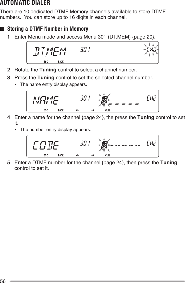
![55DUAL TONE MULTI-FREQUENCY (DTMF)The keys on the microphone keypad function as DTMF keys; the 12 keys found on a push-button telephone plus 4 additional keys (A, B, C, D). This transceiver provides 10 dedicated memory channels. You can store a DTMF number with up to 16 digits, along with a memory name of up to 8 digits in each of the channels to recall later for a quick call. Some repeaters in the U.S.A. and Canada offer a service called Autopatch. You can access the public telephone network via such a repeater by sending DTMF tones. For further information, consult your local repeater reference.MANUAL DIALINGManual Dialing requires only two steps to send DTMF tones.1 Press and hold the microphone [PTT].2 Press the keys in sequence on the keypad to send DTMF tones.• The corresponding DTMF tones are transmitted.• If the DTMF Hold function is activated, you need not hold down [PTT] while pressing keys. After transmitting the rst tone (by pressing [PTT] and the rst key), pressing additional keys will keep the transceiver in transmit mode for 2 seconds.Frequency (Hz)1209 1336 1447 1633697 [1] [2] [3] [A]770 [4] [5] [6] [B]852 [7] [8] [9] [C]941 [ ] [0] [#] [D]n DTMF Hold Activate this function to remain in transmit mode, after beginning to press keys when making a call.1 Enter Menu mode and access Menu 300 (DT.HOLD) {page 20}.2 Set DTMF Hold to ON to continue transmitting when pressing keys.• Set this menu to OFF to stop the 2 second continuous transmission.](https://usermanual.wiki/JVC-KENWOOD/397700.Instruction-Manual-2/User-Guide-768506-Page-7.png)
![57n Transmitting Stored DTMF Numbers1 Press and hold the microphone [PTT].2 While transmitting, press the Tuning control.• The last called DTMF Memory channel name and number appear on the display. If no name has been saved for the channel, the DTMF code appears.3 While still transmitting, rotate the Tuning control to select your desired DTMF Memory channel, then press the Tuning control to set the channel.• Additionally, you can press a DTMF key corresponding to your desired channel ([0] ~ [9]) to select the channel and begin transmission.• The stored DTMF number scrolls across the display and is transmitted.• The number will be transmitted even if you release [PTT] before the entire number has scrolled across the display.• If no DTMF number is stored in the selected channel, the frequency display is restored.n Selecting a Transmit Speed Some repeaters may not respond correctly if a DTMF number is transmitted at fast speed. If this happens, change the DTMF number transmission speed from FAST (default) to SLOW.1 Enter Menu mode and access Menu 302 (DT.SPD) {page 20}.2 Set the speed to FAST or SLOW.](https://usermanual.wiki/JVC-KENWOOD/397700.Instruction-Manual-2/User-Guide-768506-Page-9.png)
![59EchoLink MEMORYAUTOMATIC DIALERThere are 10 dedicated EchoLink Memory channels available. You can store up to 8 characters in each channel.n Storing EchoLink Memory1 Enter Menu mode and access Menu 204 (ELK.MEM) {page 20}.2 Rotate the Tuning control to select an EchoLink channel number from EL0 ~ EL9.3 Press the Tuning control to set the selected channel number.• The call sign entry display appears.4 Enter the call sign for the channel {page 24}, then press the Tuning control to set it.n Transmitting EchoLink Memory1 Select the band and frequency of the node to which you want to connect.2 Press and hold the microphone [PTT].3 While transmitting, press the Tuning control.• The last called Echolink/DTMF Memory channel name and number appears on the display.](https://usermanual.wiki/JVC-KENWOOD/397700.Instruction-Manual-2/User-Guide-768506-Page-11.png)
![604 While still transmitting, rotate the Tuning control to select your desired EchoLink Memory channel, then press the Tuning control to set the channel.• The stored code scrolls across the display and is transmitted.• The code will be transmitted even if you release [PTT] before the entire code has scrolled across the display.• The DTMF code of the changed Call Sign appears on the display. The Call Sign code is automatically preceeded with a “C” and ends with a “#”. DTMF values are listed in the following table:1234567890012345678901Q A D G J M P T W2Z B E H K N R U X3C F I L O S V Y So, for example, if the Call Sign being transmitted was JA1YKX, the display would read: C 51 21 10 93 52 92 #• If no data is stored in the selected channel, the frequency display is restored.](https://usermanual.wiki/JVC-KENWOOD/397700.Instruction-Manual-2/User-Guide-768506-Page-12.png)
![61n Selecting a Transmit Speed Some repeaters may not respond correctly if a code is transmitted at fast speed. If this happens, change the EchoLink transmission speed from FAST (default) to SLOW.1 Enter Menu mode and access Menu 205 (ELK.SPD) {page 20}.2 Set the speed to FAST or SLOW.SETTING UP EchoLink MODEWhen connected to a PC, you can set whether or not to use the RTS and CTS terminals for hard ow control, or the SQC and PKS terminals for EchoLink.1 Turn the transceiver power OFF.2 Press [PF2] + Power ON to turn EchoLink ON.• The icon appears on the display when EchoLink is ON.• To turn EchoLink OFF, press [PF2] + Power ON again.EchoLink Mode ON EchoLink Mode OFFTM-V71 PC TM-V71 PCTxD –> RxD TxD –> RxDRxD <– TxD RxD <– TxDSQC –> CTS RTS –> CTSPKS <– RTS CTS <– RTSGND <–> GND GND <–> GNDNote: When in EchoLink mode, you cannot change to Repeater mode or Remote Control mode.](https://usermanual.wiki/JVC-KENWOOD/397700.Instruction-Manual-2/User-Guide-768506-Page-13.png)
![62AUXILIARY FUNCTIONSPOWER-ON MESSAGEEach time you switch the transceiver ON, “HELLO” (default) appears on the display for approximately 2 seconds. You can program your favorite message in place of the default message.1 Enter Menu mode and access Menu 500 (P.ON.MSG) {page 20}.2 Enter your desired message {page 24}. • Press [PF1] (CLR) to clear the entire message, if necessary.DISPLAY BRIGHTNESSYou can manually change the display illumination to suit the lighting conditions where you are operating.1 Enter Menu mode and access Menu 501 (BRIGHT) {page 20}.2 Set your desired brightness level from 1 to 8, or OFF. • Press [PF1] (CLR) to clear the entire message, if necessary.n Auto Display Brightness When Auto Brightness is activated, the display will light up every time a key is pressed.1 Enter Menu mode and access Menu 502 (AUTO.BR) {page 20}.2 Set the Auto Brightness function to ON or OFF.](https://usermanual.wiki/JVC-KENWOOD/397700.Instruction-Manual-2/User-Guide-768506-Page-14.png)
![63n Backlight Color You can manually change the display illumination to suit the lighting conditions where you are operating.1 Enter Menu mode and access Menu 503 (COLOR) {page 20}.2 Set the backlight color to AMBER or GREEN. KEY LOCKThe Key Lock function ensures that your transceiver settings will remain unchanged if you accidentally press a key. When activated, the following functions can still be used:• [ ]• [PTT]• microphone [PF]To turn Key Lock ON or OFF, press [F] (1s).• When Key Lock is activated, the icon will appear on the display.n Microphone Key Lock The Microphone Key Lock function will lock the microphone PF (Progammable Function) keys.1 Enter Menu mode and access Menu 513 (MIC.LCK) {page 20}.2 Turn the Micrphone Key Lock function ON or OFF.](https://usermanual.wiki/JVC-KENWOOD/397700.Instruction-Manual-2/User-Guide-768506-Page-15.png)
![64KEY BEEPYou can turn the transceiver beep function ON or OFF as desired.1 Enter Menu mode and access Menu 000 (BEEP) {page 20}.2 Turn the beep function ON or OFF. • Even with the beep function turned OFF, the transceiver will emit a beep tone under the following conditions:1) When Auto Power Off is activated, the transceiver will beep 1 minute before the power turns off.2) After transmitting for the maximum time duration according to the Time-out Timer, the transceiver will beepn Beep Volume Each time you press a key, the beep tone will sound. If you have left the beep function turned ON, you may wish to adjust the volume level of the beep.1 Enter Menu mode and access Menu 001 (BP.VOL) {page 20}.2 Set the beep volume to a level from 1 to 7.• The default is level 5.PROGRAMMABLE VFOIf you always check frequencies within a certain range, you can set upper and lower limits for frequencies that are selectable. For example, if you select 144 MHz for the lower limit and 145 MHz for the upper limit, the tunable range will be from 145.000 MHz to 146.995 MHz.1 Press the left or right [BAND SEL] to set band A or B as the operating band, then press [VFO].2 Enter Menu mode and access Menu 100 (PRG.VFO) {page 20}. (Example: E type)](https://usermanual.wiki/JVC-KENWOOD/397700.Instruction-Manual-2/User-Guide-768506-Page-16.png)
![653 Press the Tuning control.• The lower frequency limit blinks.4 Rotate the Tuning control to select your desired lower frequency limit, then press the Tuning control to set the selected value.• The upper frequency limit blinks.• When setting the limit for the 1200 MHz band, the 1 MHz digit appears on the 7-segment display to the right of the main display.5 Rotate the Tuning control to select your desired upper frequency limit, then press the Tuning control to set the selected value.6 Press [CALL] (ESC) to exit Menu mode.Note: You cannot program the 100 kHz and subsequent digits. The exact 100 kHz and subsequent digits of the upper limit depend on the frequency step size you are using.CHANGING THE FREQUENCY STEP SIZEChoosing the correct frequency step size is essential in selecting your exact frequency. The default step size on the 144 MHz band is 5 kHz (K type) or 12.5 kHz (E, M4 types). The default on the 430/440 MHz band is 25 kHz. For K type models, the default on the 118, 220, or 300 MHz band is 12.5 kHz and the default on the 1200 MHz band is 25 kHz. 1 Press the left or right [BAND SEL] to select band A or B, then press [VFO].2 Enter Menu mode and access Menu 101 (STEP) {page 20}.3 Set the step size to 5.0*, 6.25*, or 8.33 kHz (118 MHz band only) or to 10.0, 12.5*, 15.0, 20.0, 25.0, 30.0, 50.0, or 100.0 kHz.* These step sizes are not available for the 1200 MHz band.Note: Changing between step sizes may correct the displayed frequency. For example, if 144.995 MHz is displayed with a 5 kHz step size selected, changing to a 12.5 kHz step size corrects the displayed frequency to 144.9875 MHz.](https://usermanual.wiki/JVC-KENWOOD/397700.Instruction-Manual-2/User-Guide-768506-Page-17.png)
![66PROGRAMMABLE FUNCTION KEYSn Transceiver Front Panel There are 2 PF (Programmable Function) keys on the transceiver front panel: PF1 and PF2. You can assign your own desired functions to these 2 keys.1 Enter Menu mode and access Menu 507 (PF1) and/or Menu 508 (PF2) {page 20}.2 Set your desired function for the key. Programmable functions available are: WX CH (Weather Channel)/ FR.BAND/ CTRL (Control)/ MONI (Monitor)/ VGS/ VOICE (Voice ON/OFF)/ GRP.UP/ MENU (Menu mode)/ MUTE (Speaker Mute)/ SHIFT (Shift)/ DUAL (Dual Mode)/ M>V (Memory to VFO Copy)/ 1750 (1750 Hz Tone).n Microphone Keys There are 4 microphone PF (Programmable Function) keys: [PF] (PF1), [MR] (PF2), [VF0] (PF3) and [CALL] (PF4). You can assign your own desired functions to these 4 keys.1 Enter Menu mode and access Menu 509 (MIC.PF1) and/or Menu 510 (MIC. PF2) and/or Menu 511 (MIC. PF2) and/or Menu 512 (MIC. PF2) {page 20}.2 Set your desired function for the key. Programmable functions available are: WX CH (Weather Channel)/ FR.BAND/ CTRL (Control)/ MONI (Monitor)/ VGS/ VOICE (Voice ON/OFF)/ GRP.UP/ MENU (Menu mode)/ MUTE (Speaker Mute)/ SHIFT (Shift)/ DUAL (Dual Mode)/ M>V (Memory to VFO Copy)/ VFO/ MR/ CALL/ MHz/ TONE/ REV (Reverse)/ LOW/ LOCK/ A/B (Band Select A/ Band Select B)/ ENTER/ 1750 (1750 Hz Tone).](https://usermanual.wiki/JVC-KENWOOD/397700.Instruction-Manual-2/User-Guide-768506-Page-18.png)
![67FREQUENCY DIRECT ENTRYIf the desired operating frequency is far from the current frequency, using the microphone keypad is the quickest way to change the frequency. One of the microphone PF keys must rst be programmed as ENTER {page 66},1 Press the left or right [BAND SEL] to select band A or B, then press [VFO] or [CALL].2 Press the key programmed as [ENTER].• The Direct Frequency Entry display appears.3 Press the microphone keys ([0] ~ [9]) to enter your desired frequency.4 To set the entered frequency, press [ENTER] or [VFO].• Pressing [ENTER] before entering all of the digits will set the remaining digits to 0.• Pressing [VFO] before entering all of the digits will leave the remaining digits at their previous values.• Entering all digits for a frequency will automatically set the frequency without pressing [ENTER] or [VFO].• If you need to only change the MHz digit, press the Tuning control, then enter the new value.AUTOMATIC POWER OFF (APO)Automatic Power Off is a background function that monitors whether or not any operations have been performed (keys pressed, Tuning control turned, etc.), and turns the transceiver power OFF if it has not been in use.1 Enter Menu mode and access Menu 516 (APO) {page 20}.2 Set the APO time limit to 30, 60, 90, 120, 180 minutes, or OFF.• After the time limit passes with no operations (default is 180 minutes), APO turns the transceiver power OFF. However, 1 minute before the power turns OFF, “APO” appears on the display and blinks, and a warning tone sounds.Note: If any settings are changed during while APO is ON, the timer resets. When you stop changing the settings, the timer begins counting again from 0.](https://usermanual.wiki/JVC-KENWOOD/397700.Instruction-Manual-2/User-Guide-768506-Page-19.png)
![69SWITCHING FM/AM MODEThis transceiver is also capable of receiving (not transmitting) in AM on band A. The default mode on the 118 MHz band is AM while the default on the 144, 220, 300, or 430/440 MHz band is FM.1 Enter Menu mode and access Menu 102 (MODLAT) {page 20}.2 Set the mode to AM, FM, or NFM.Note: You cannot switch between FM and AM to receive on band B.BEAT SHIFTSince the transceiver uses a microprocessor to control various transceiver functions, the CPU clock oscillator’s harmonics or image may appear on some spots of the reception frequencies. In this case, we recommend you turn the Beat Shift function ON.1 Enter Menu mode and access Menu 108 (B.SHIFT) {page 20}.2 Set the Beat Shift to ON or OFF.SPEAKER MUTEWhile receiving or transmitting on the TX band, you may not want to hear audio received on the other band. Use this function to mute the speaker allocated to that band (not the TX band).While receiving, press [LOW] to switch the mute function ON or OFF.• The icon appears on the display when the function is ON.](https://usermanual.wiki/JVC-KENWOOD/397700.Instruction-Manual-2/User-Guide-768506-Page-21.png)
![70n Mute Hang Time When using Speaker Mute, you may want to adjust the time interval between when you receive a signal and when the speaker is muted. 1 Enter Menu mode and access Menu 107 (MUT.HNG) {page 20}.2 Set the hang time to 125, 250, 500, 750, or 1000 ms.SELECTING AN OUTPUT POWERIt is a good idea to select lower transmit power if communications is still reliable. This lowers the risk of interfering with others on the band. When operating from battery power, you will enjoy more operating time before a recharge is necessary. Press [LOW] to select high (H) (K, E types only), medium (M), or low (L) power. The default is high.• You can program different power settings for bands A and B.Note: When the transceiver overheats because of ambient high temperature or continuous transmission, the protective circuit may function to lower transmit output power. TIME-OUT TIMER (TOT)It is sometimes necessary or desirable to restrict a single transmission to a specic maximum time. You may use this function to prevent repeater time-outs when accessing repeaters, or to conserve battery power.When TOT times out (default is 10 minutes), the transceiver generates beeps and automatically returns to receive mode. To resume transmitting, release and then press the microphone [PTT] again.1 Enter Menu mode and access Menu 109 (TOT) {page 20}.2 Set the timer to 3, 5, or 10 minutes.](https://usermanual.wiki/JVC-KENWOOD/397700.Instruction-Manual-2/User-Guide-768506-Page-22.png)
![71EXTERNAL SPEAKER CONFIGURATIONThis transceiver has two speaker jacks for external speakers, as well as an internal speaker. You can enjoy a variety of speaker congurations by using one or two external speakers. Received signals on bands A and B are output depending on how you want the internal and/or external speakers to function.1 Enter Menu mode and access Menu 002 (EXT.SP) {page 20}.2 Set the speaker mode to MODE 1 or MODE 2.• Refer to the table below for congurations based on the mode selected.Mode Speaker SetupBand OutputInternal Speaker External SP1 External SP2MODE 1None A, B – –SP1 only x A, B –SP2 only A – BSP1, SP2 x A BMODE 2None A, B – –SP1 only x A, B –SP2 only B – ASP1, SP2 x B AMASKING A BANDIf you have no plans to use band A or B, you can hide the frequency display on the unused band. This saves power consumption and makes it simpler to read the information you need.1 Turn the transceiver power OFF.2 Press the left or right [BAND SEL] + Power ON.• The band mask display appears.3 Rotate the Tuning control to select the band you want to hide (or return to normal).](https://usermanual.wiki/JVC-KENWOOD/397700.Instruction-Manual-2/User-Guide-768506-Page-23.png)
![724 Press the Tuning control to set the selected band.5 Rotate the Tuning control to set the band to select USE or MASK.• USE allows you to see and use the band as normal. MASK hides the band on the display.6 Press the Tuning control to set the selection.7 Press the [CALL] (ESC) to exit.Note: You cannot operate the masked band nor use it to receive or transmit.DISPLAY PARTITION BARThe partition bar that appears between bands A and B can be removed if desired.1 Enter Menu mode and access Menu 527 (DP.BAR) {page 20}.2 Set the partition bar display to ON or OFF.](https://usermanual.wiki/JVC-KENWOOD/397700.Instruction-Manual-2/User-Guide-768506-Page-24.png)
![74PASSWORD PROTECTIONIf password protection is activated, you cannot operate the transceiver without rst entering your password, after turning the transceiver power ON. Your password can be changed using the MCP control software.The password can contain up to 6 digits. When using the front panel keys, you can enter digits from 1 ~ 5. When using the microphone keypad, you can enter digits from 0 ~ 9 and A ~ F.1 Enter Menu mode and access Menu 998 (PROTEC) {page 20}.2 Set the password protection to ON or OFF.• When set to ON, “PASSWD” appears on the display.3 Enter your password using the microphone keypad or the transceiver front panel keys.• When using the transceiver front panel keys, they operate as follows: [CALL]: 1 [F]: 2 [TONE]: 3 [REV]: 4 [LOW]: 54 After entering up to 6 digits, press the Tuning control to set the password.](https://usermanual.wiki/JVC-KENWOOD/397700.Instruction-Manual-2/User-Guide-768506-Page-26.png)
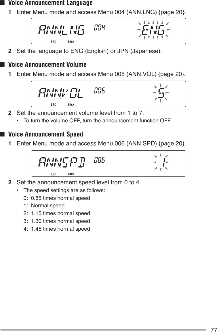
![75VGS-1 OPTIONAL VOICE GUIDE & STORAGE UNITWhen using the optional VGS-1 voice guide & storage unit, you gain access to the voice recorder and voice announcement functions. VOICE ANNOUNCEMENTSWhen changing modes, frequencies, settings, etc., an audio voice will announce the new information.1 Enter Menu mode and access Menu 003 (ANN) {page 20}.2 Set the announcement function to MANUAL, AUTO, or OFF.• Refer to the tables below for announcements based on settings.MANUAL: A microphone PF key must be programmed as [VOICE] to use MANUAL voice announcment.Operation AnnouncementWhile in VFO mode Press [VOICE]: Operating band frequencyWhile in MR modePress [VOICE]: “Channel” + Channel number + operating band frequencyWhile in Call mode Press [VOICE]: “Call channel” + operating band frequencyWhile in Menu modePress [VOICE]: Menu number or setting value (some selections have no voice announcement)While setting up Tone/CTCSS/DCSPress [VOICE]: Current frequency/code](https://usermanual.wiki/JVC-KENWOOD/397700.Instruction-Manual-2/User-Guide-768506-Page-27.png)
![76AUTO: Announcements are made automatically when changing a mode/frequency/setting.Operation AnnouncementPress [VFO] “VFO”Press [MR] “MR”Press [CALL] “Call”Press [MENU] “Menu” + menu numberPress [PM] “PM”Press [ENT] “Enter”Change the operating band/ turn the power ON“A”/“B” + “Channel” (for MR only) + “Call”/channel number + “Channel (for CALL only) + operating band frequency + output power levelChange the frequency band New receive frequencySetting up the PM Channel number/“Off”Frequency direct entry Entered key numberMemory Direct Entry mode Channel numberPress [F] in VFO mode “Memory in” + channel number + frequencyPress [F], [M.IN] in VFO mode “Memory in” + channel number + “Blank”Press [A/B] in VFO mode “A”/“B” + frequency + output power levelPress [F] and then the Tuning control in VFO mode “Menu” + menu numberPress the Tuning control in Menu mode Setting valuePerform a Full Reset “Full reset?”Perform a Partial Reset “Partial reset?”Perform a VFO Reset “VFO reset?”Perform a PM Reset “PM reset?”Press [LOCK] (to turn the Lock function ON) “Lock on”Press [LOCK] (to turn the Lock function OFF) “Lock off”Tone frequency setup “Tone frequency” + frequency valueCTCSS frequency setup “CTCSS frequency” + frequency valueDCS code setup “DCS” + code valueMHz step frequency setup “MHz Step” + frequency value10 MHz setup “10” + “MHz setup” + frequency valueOutput power setup “TX Power” + power level](https://usermanual.wiki/JVC-KENWOOD/397700.Instruction-Manual-2/User-Guide-768506-Page-28.png)
![78VOICE RECORDERThe voice recorder provides you with 3 VGS channels for recording voice memos, along with a single VGS channel for recording conversations. You can also prepare automated message responses to received calls.Each recording can last for up to 30 seconds.■ Voice Memos To record a voice memo, for later playback:1 Press the PF key programmed as [VGS].2 Press and hold the key for the VGS channel number you want to store the memo in: [F] (1), [TONE] (2), or [REV] (3).• A beep will sound and the transceiver will enter Recording mode.3 Press and hold the VGS channel number key again (the same key you pressed in the previous step), then speak into the microphone to record your memo.• Recording begins as soon as you press the VGS channel number key, and a timer appears on the display.• Pressing the microphone PTT switch at this time will transmit your message as well as record it. Do not press the microphone PTT switch if you do not want to transmit your message.4 Release the VGS channel number key to end the recording at any time and store it into the selected VGS channel.• If the memory becomes full, recording will stop automatically and store the voice memo to memory.• “WRITING” appears on the display while the recording is being stored to memory.](https://usermanual.wiki/JVC-KENWOOD/397700.Instruction-Manual-2/User-Guide-768506-Page-30.png)
![79■ Conversation Recorder To record a 30 second conversation:1 Enter Menu mode and access Menu 009 (CON.REC) {page 20}.2 Set the Conversation Recorder to ON (or OFF). • The icon appears on the display when this function is activated. The icon does not appear during playback, in Repeater mode, or in Remote Control mode. 3 Press the PF key programmed as [VGS].4 Press [LOW] (4) (1s) to store the conversation in VGS channel 4.](https://usermanual.wiki/JVC-KENWOOD/397700.Instruction-Manual-2/User-Guide-768506-Page-31.png)
![80■ Playback1 Press the PF key programmed as [VGS].2 Press the key for the VGS channel number you want to play back: [F] (1), [TONE] (2), [REV] (3), or [LOW] (4).• The recording saved in the channel you selected is played back.• To end playback at any time, press [PF1] (CLR).• To exit, press [VGS] again.• During playback, you can switch to any of recordings 1, 2, or 3 by pressing the appropriate key.• While playing a recording, you can transmit the recording by pressing the [PTT] switch. (Continue holding the [PTT] switch until the entire recording is transmitted.)■ Playback Repeat You can set messages to be repeatedly played back. 1 Enter Menu mode and access Menu 007 (PLAY.BK) {page 20}.2 Set the the Playback Repeat function to ON or OFF.■ Playback Repeat Interval If the Playback Repeat function is activated, you can set a time interval for how often the memo/message is played back. 1 Enter Menu mode and access Menu 008 (P.BK.INT) {page 20}.2 Set the interval from 0 to 60 seconds.](https://usermanual.wiki/JVC-KENWOOD/397700.Instruction-Manual-2/User-Guide-768506-Page-32.png)
![81CROSS-BAND/ LOCKED-BAND OPERATION (K TYPE MODELS ONLY)This transceiver is capable of receiving signals on one band and retransmitting signals on the other band. This function repeats signals originating from one band, using the other band. For example, a signal received on band A (VHF) is retransmitted on band B (UHF). Similarly, a signal received on band B (UHF) is retransmitted on band A (VHF).Locked-band Repeater: The transceiver uses the same band to receive or transmit a signal. You can set either the A band (A-TX) or B band (B-TX) as the transmit band.Cross-band Repeater: If receiving a signal on the TX band, the transceiver switches the current RX only band to the TX band. This is useful when joining in a group talk. Participants in a group talk need to set a receive and transmit frequency on different bands so as not to miss any conversation within the group.1 Enter Menu mode and access Menu 403 (RPT.MOD) {page 20}.2 Set the Repeater operation mode to CROSS (cross-band), A-TX (A band), or B-TX (B band).3 Turn the transceiver power OFF.4 Press [TONE] + Power ON.• The Repeater mode is ON and the and icons blink on the display.• You are unable to perform any transceiver functions while in Repeater mode.• To return to normal operation, turn the transceiver power OFF, then press [TONE] + Power ON.Note:u You cannot activate the Repeater function while in single band operating mode or Weather Channel mode. u Activating the Repeater function switches OFF the Automatic Simplex Checker (ASC).u The Time-Out Timer is locked at 3 minutes.u Resetting the transceiver {page 88} will not cancel the Repeater mode.](https://usermanual.wiki/JVC-KENWOOD/397700.Instruction-Manual-2/User-Guide-768506-Page-33.png)

![8610 Press [REV] + Power ON to enter Remote Control mode.• The and icons appear on the display.• To exit Remote Control operation, turn the transceiver power OFF, then press [REV] + Power ON again. CONTROL OPERATIONWhile in Remote Control mode, the DTMF keys of the handheld will function as shown in the table below. Each time you press the desired key, the handheld will automatically enter transmit mode and send the corresponding command to the mobile.Operation DTMF CommandAccess your mobile via the remote unit (where *** is your 3-digit secret number) A *** #End access of your mobile via the remote unit A #DCS ON 1Tone ON 2CTCSS ON 3DCS OFF (all signalling OFF) 4Tone OFF (all signalling OFF) 5CTCSS OFF (all signalling OFF) 6Call mode ON 7VFO mode ON 8Memory mode ON 9Transmit power (press to toggle between High, Medium, and Low) 0Frequency (in VFO mode) or Memory channel (in Memory mode) directy entry A XXXXXXXDCS code (when DCS is ON), Tone frequency (when Tone is ON), or CTCSS frequency (when CTCSS is ON) setup B XXXRepeater (Cross-band or Locked-band) ON CRepeater OFF DStep the frequency or Memory channel downStep the frequency or Memory channel up #](https://usermanual.wiki/JVC-KENWOOD/397700.Instruction-Manual-2/User-Guide-768506-Page-38.png)
![87TRANSCEIVER RESETThere are 4 types of transceiver reset available:VFO Reset Use to initialize the VFO and accompanying settings.PART (Partial) Reset Use to initialize all settings other than the Memory channels, the DTMF memory, and the PM channels.PM Reset Use to reset only the Programmable Memory channels to their default values.FULL Reset Use to initialize all transceiver settings that you have customized.There are 2 ways to perform a reset on the transceiver: by key operation and by accessing Menu mode.Key Operation:1 Turn the transceiver power OFF.2 Press [F] + Power ON.3 Rotate the Tuning control and select your desired reset type: VFO, PART, PM, or FULL. 4 Press the Tuning control to set the reset type.• Aconrmationmessageappearsonthedisplay.• Press [TONE] (BACK) to return to the previous display or [F] (ESC) to cancel the reset.5 Press the Tuning control again to perform the reset.Note: When in Remote Control or Repeater mode, you cannot reset the transceiver using the Key Operation method.](https://usermanual.wiki/JVC-KENWOOD/397700.Instruction-Manual-2/User-Guide-768506-Page-39.png)
![88Menu Mode:1 Enter Menu mode and access Menu 999 (RESET) {page 20}.2 Set the reset type to VFO, PART, PM, or FULL.3 Press the Tuning control to set the reset type.• Aconrmationmessageappearsonthedisplay.• Press [TONE] (BACK) to return to the previous display or [F] (ESC) to cancel the reset.4 Press the Tuning control again to perform the reset.Note: When the Channel Display function or Key Lock function is ON, the transceiver reset cannot be performed.](https://usermanual.wiki/JVC-KENWOOD/397700.Instruction-Manual-2/User-Guide-768506-Page-40.png)
![95TROUBLESHOOTINGThe problems described in this table are commonly encountered operational malfunctions and are usually not caused by circuit failure.Problem Probable Cause Corrective ActionThe transceiver will not power up after connecting a 13.8 V DC power supply and pressing [ ]. Nothing appears on the display.1 The power cable was connected backwards. 2 One or more of the power cable fuses are open.1 Connect the supplied DC power cable correctly (red to + terminal and black to – terminal).2 Look for the cause of the blown fuse(s). After inspecting and correcting any problems, install a new fuse(s) with the same ratings.The frequency cannot be selected by turning the Tuning control or by pressing microphone [UP]/[DWN].Memory Recall was selected.Press [VFO].Most keys and the Tuning control do not function.1 One of the Lock functions is ON.2 The transceiver is in Channel Display mode.1 Unlock all of the Lock functions.2 With the transceiver power OFF, press [REV] + Power ON to exit Channel Display mode.Memory channels cannot be selected by turning the Tuning control or by pressing microphone [UP]/[DWN].No data has been stored in any Memory channel.Store data in some Memory channels.You cannot transmit even though you are pressing [PTT].1 The microphone plug was not inserted completely into the transceiver.2 You selected a transmit offset that places the transmit frequency outside the allowable range.3 The external TNC is transmitting.1 Switch the power OFF, then insert the microphone plug until the locking tab clicks in place.2 Turn the offset shift function OFF. 3 Press [PTT] after the TNC has nished transmitting.](https://usermanual.wiki/JVC-KENWOOD/397700.Instruction-Manual-2/User-Guide-768506-Page-47.png)