JVC KENWOOD 397700 Scanning Receiver User Manual Instruction Manual 2
JVC KENWOOD Corporation Scanning Receiver Instruction Manual 2
Contents
- 1. Instruction Manual 1
- 2. Instruction Manual 2
- 3. User Manual
- 4. User Instructions Guide
- 5. User Guide Instructions
Instruction Manual 2
49
CONTINUOUS TONE CODED SQUELCH SYSTEM (CTCSS)
You may sometimes want to hear calls only from specic persons. The
Continuous Tone Coded Squelch System (CTCSS) allows you to ignore (not hear)
unwanted calls from other persons who are using the same frequency. To do
so, select the same CTCSS tone as selected by the other persons in your group.
A CTCSS tone is subaudible and is selectable from among 42 standard tone
frequencies.
Note: CTCSS does not cause your conversation to be private. It only relieves you from listening
to unwanted conversations.
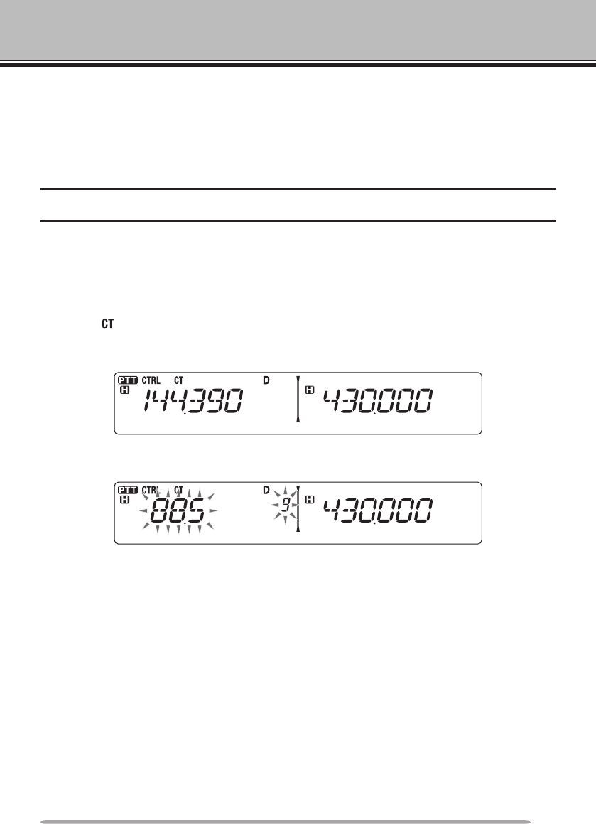
USING CTCSS
1 Select your desired band.
2 Press [TONE] 2 times to activate the CTCSS function.
• The icon appears on the display when the CTCSS function is ON.
• Each press of [TONE] changes the selection as follows:
Tone (T) –> CTCSS (CT) –> DCS (DCS) –> Off (no display).
3 Press [F], [TONE].
• The current CTCSS frequency appears on the display and blinks.
4 Rotate the Tuning control to select your desired CTCSS frequency.
• Refer to the table below for the available frequencies.
• To exit the CTCSS frequency selection, press [F] (ESC).
5 Press any key other than the Tuning control and [F] (ESC) to complete the
setting.
6 When you are called: The transceiver squelch opens only when the selected
CTCSS tone is received.
When you make a call: Press and hold [PTT], then speak into the microphone.
• To cancel CTCSS, press [TONE] until CT no longer appears on the display.
50
You can also select a CTCSS frequency by using the microphone:
1 Select your desired band.
2 Press [TONE] 2 times to activate the CTCSS function.
• The icon appears on the display when the CTCSS function is ON.
• Each press of [TONE] changes the selection as follows:
Tone (T) –> CTCSS (CT) –> DCS (DCS) –> Off (no display).
3 Press [F], [TONE].
• The current CTCSS frequency appears on the display and blinks.
4 Press the key programmed as [ENTER].
5 Enter a frequency reference number (01 ~ 42) using the microphone keypad.
• Refer to the table below for frequencies and their reference numbers.
6 Press [ENTER] again to complete the setting.
No. Frequency
(Hz) No. Frequency
(Hz) No. Frequency
(Hz) No. Frequency
(Hz)
01 67.0 12 97.4 23 141.3 34 206.5
02 69.3 13 100.0 24 146.2 35 210.7
03 71.9 14 103.5 25 151.4 36 218.1
04 74.4 15 107.2 26 156.7 37 225.7
05 77.0 16 110.9 27 162.2 38 229.1
06 79.7 17 114.8 28 167.9 39 233.6
07 82.5 18 118.8 29 173.8 40 241.8
08 85.4 19 123.0 30 179.9 41 250.3
09 88.5 20 127.3 31 186.2 42 254.1
10 91.5 21 131.8 32 192.8
11 94.8 22 136.5 33 203.5
51
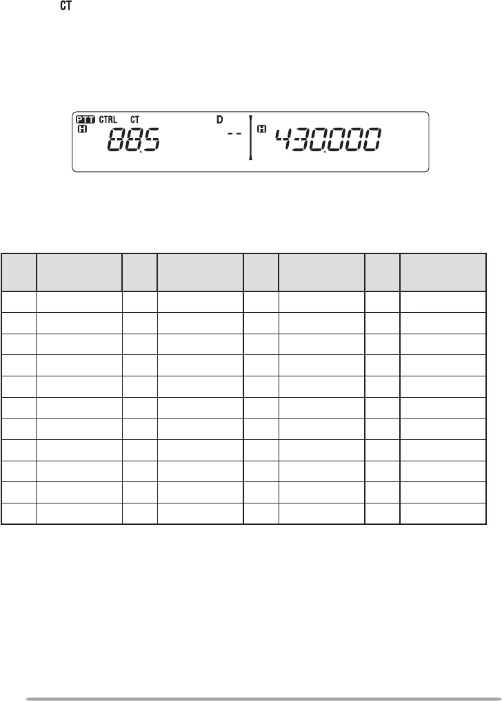
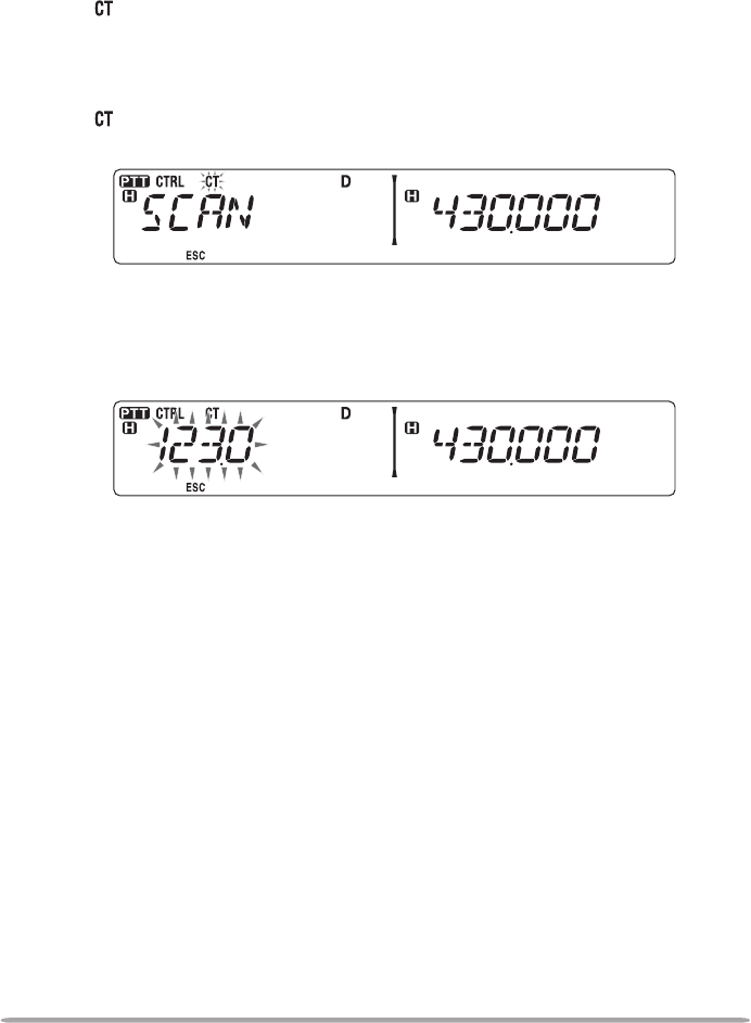
CTCSS FREQUENCY ID
This function scans through all CTCSS frequencies to identify the incoming
CTCSS frequency on a received signal. You may nd this useful when you
cannot recall the CTCSS frequency that the other persons in your group are
using.
1 Press [TONE] 2 times to activate the CTCSS function.
• The icon appears on the display when the CTCSS function is ON.
• Each press of [TONE] changes the selection as follows:
Tone (T) –> CTCSS (CT) –> DCS (DCS) –> Off (no display).
2 Press [F], [TONE] (1s).
• The icon blinks and “SCAN” appears on the display.
• Scan starts when a signal is received.
• To reverse the scan direction, turn the Tuning control clockwise (upward scan) or
counterclockwise (downward scan). You can also press microphone [UP]/ [DWN].
• To quit the scan, press [F] (ESC).
• When a CTCSS frequency is identied, the identied frequency appears on the
display and blinks.
3 Press the Tuning control to program the identied frequency in place of the
currently set CTCSS frequency.
• The CTCSS function will remain ON. To cancel CTCSS, press [TONE] until CT no
longer appears on the display.
• Press [F] (ESC) if you do not want to program the identied frequency.
• Rotate the Tuning control while an identied frequency is blinking, to resume
scanning.
52
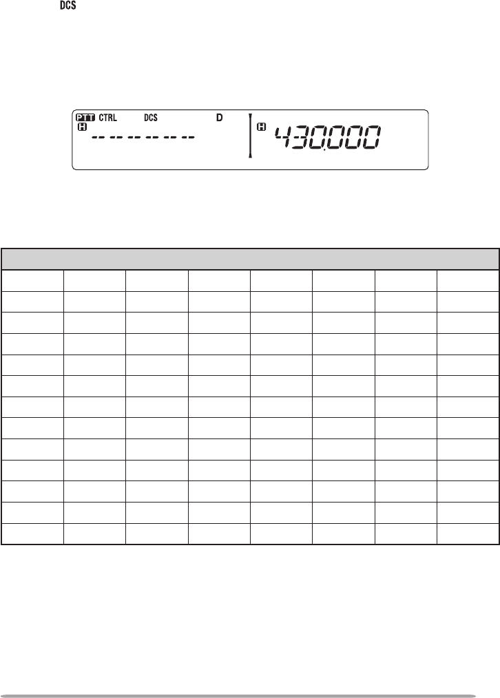
DIGITAL CODED SQUELCH (DCS)
Digital Code Squelch (DCS) is another application which allows you to ignore (not
hear) unwanted calls. It functions the same way as CTCSS. The only differences
are the encode/ decode method and the number of selectable codes. For DCS,
you can select from 104 different codes.
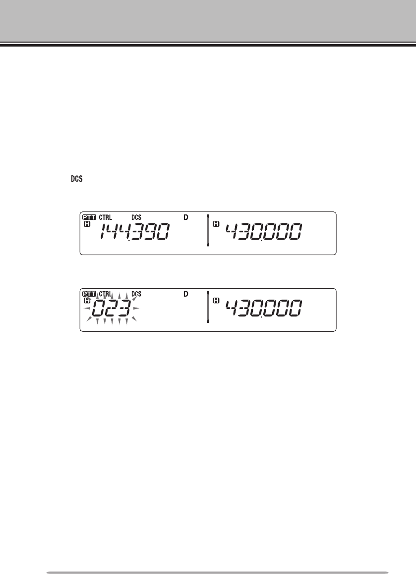
USING DCS
1 Select your desired band.
2 Press [TONE] 3 times to activate the DCS function.
• The icon appears on the display when the DCS function is ON.
• Each press of [TONE] changes the selection as follows:
Tone (T) –> CTCSS (CT) –> DCS (DCS) –> Off (no display).
3 Press [F], [TONE].
• The current DCS code appears on the display and blinks.
4 Rotate the Tuning control to select your desired DCS code.
• Refer to the table below for the available codes.
• To exit the DCS code selection, press [F] (ESC).
5 Press any key other than the Tuning control and [F] (ESC) to complete the
setting.
6 When you are called: The transceiver squelch opens only when the selected
DCS code is received.
When you make a call: Press and hold [PTT], then speak into the microphone.
• To cancel DCS, press [TONE] until DCS no longer appears on the display.
53
You can also select a DCS code by using the microphone:
1 Select your desired band.
2 Press [TONE] 3 times to activate the DCS function.
• The icon appears on the display when the DCS function is ON.
• Each press of [TONE] changes the selection as follows:
Tone (T) –> CTCSS (CT) –> DCS (DCS) –> Off (no display).
3 Press [F], [TONE].
• The current DCS code appears on the display and blinks.
4 Press the key programmed as [ENTER].
5 Enter your desired DCS code using the microphone keypad.
• Refer to the table below for DCS codes.
6 Press [ENTER] again to complete the setting.
DCS Code
023 025 026 031 032 036 043 047
051 053 054 065 071 072 073 074
114 115 116 122 125 131 132 134
143 145 152 155 156 162 165 172
174 205 212 223 225 226 243 244
245 246 251 252 255 261 263 265
266 271 274 306 311 315 325 331
332 343 346 351 356 364 365 371
411 412 413 423 431 432 445 446
452 454 455 462 624 465 466 503
506 516 523 565 532 546 565 606
612 624 627 631 632 654 662 664
703 712 723 731 732 734 743 754
54
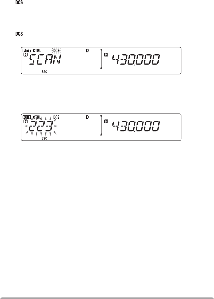
DCS CODE ID
This function scans through all DCS codes to identify the incoming DCS code on
a received signal. You may nd it useful when you cannot recall the DCS code
that the other persons in your group are using.
1 Press [TONE] 3 times to activate the DCS function.
• The icon appears on the display when the DCS function is ON.
• Each press of [TONE] changes the selection as follows:
Tone (T) –> CTCSS (CT) –> DCS (DCS) –> Off (no display).
2 Press [F], [TONE] (1s).
• The icon blinks and “SCAN” appears on the display.
• Scan starts when a signal is received.
• To reverse the scan direction, turn the Tuning control clockwise (upward scan) or
counterclockwise (downward scan). You can also press microphone [UP]/ [DWN].
• To quit the scan, press [F] (ESC).
• When a DCS code is identied, the identied code appears on the display and
blinks.
3 Press the Tuning control to program the identied code in place of the
currently set DCS code.
• The DCS function will remain ON. To cancel DCS, press [TONE] until DCS no
longer appears on the display.
• Press [F] (ESC) if you do not want to program the identied code.
• Rotate the Tuning control while an identied code is blinking, to resume scanning.
55
DUAL TONE MULTI-FREQUENCY (DTMF)
The keys on the microphone keypad function as DTMF keys; the 12 keys found
on a push-button telephone plus 4 additional keys (A, B, C, D). This transceiver
provides 10 dedicated memory channels. You can store a DTMF number with up
to 16 digits, along with a memory name of up to 8 digits in each of the channels to
recall later for a quick call.
Some repeaters in the U.S.A. and Canada offer a service called Autopatch. You
can access the public telephone network via such a repeater by sending DTMF
tones. For further information, consult your local repeater reference.
MANUAL DIALING
Manual Dialing requires only two steps to send DTMF tones.
1 Press and hold the microphone [PTT].
2 Press the keys in sequence on the keypad to send DTMF tones.
• The corresponding DTMF tones are transmitted.
• If the DTMF Hold function is activated, you need not hold down [PTT] while pressing
keys. After transmitting the rst tone (by pressing [PTT] and the rst key), pressing
additional keys will keep the transceiver in transmit mode for 2 seconds.
Frequency (Hz)
1209 1336 1447 1633
697 [1] [2] [3] [A]
770 [4] [5] [6] [B]
852 [7] [8] [9] [C]
941 [ ] [0] [#] [D]
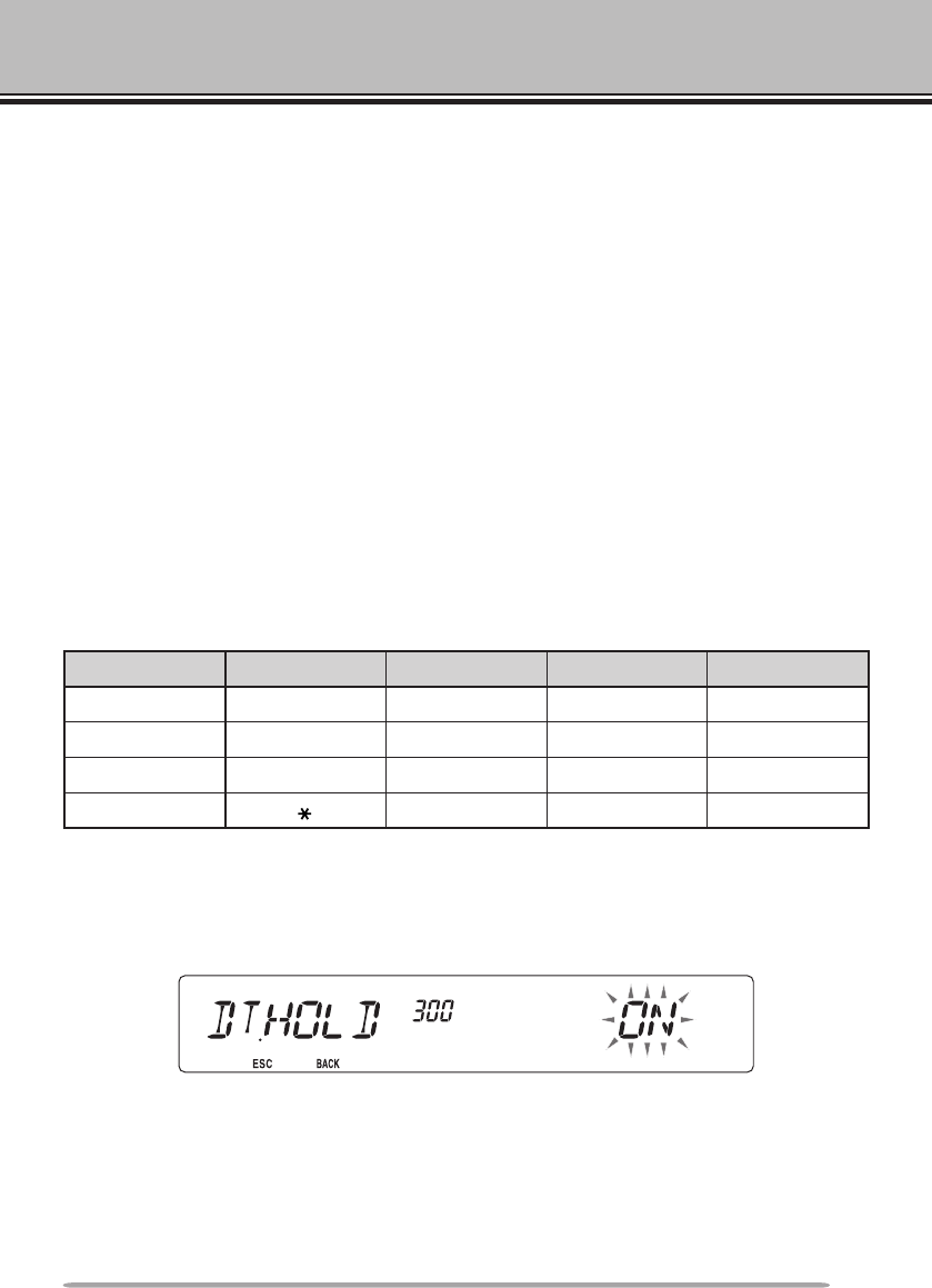
n DTMF Hold
Activate this function to remain in transmit mode, after beginning to press keys
when making a call.
1 Enter Menu mode and access Menu 300 (DT.HOLD) {page 20}.
2 Set DTMF Hold to ON to continue transmitting when pressing keys.
• Set this menu to OFF to stop the 2 second continuous transmission.
56
AUTOMATIC DIALER
There are 10 dedicated DTMF Memory channels available to store DTMF
numbers. You can store up to 16 digits in each channel.
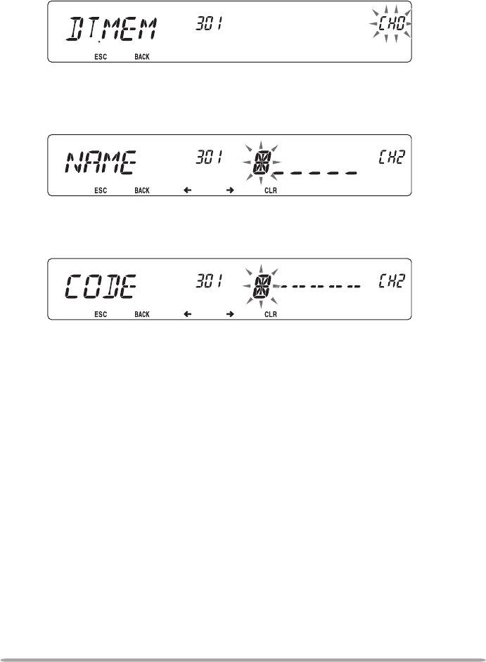
n Storing a DTMF Number in Memory
1 Enter Menu mode and access Menu 301 (DT.MEM) {page 20}.
2 Rotate the Tuning control to select a channel number.
3 Press the Tuning control to set the selected channel number.
• The name entry display appears.
4 Enter a name for the channel {page 24}, the press the Tuning control to set
it.
• The number entry display appears.
5 Enter a DTMF number for the channel {page 24}, then press the Tuning
control to set it.
57
n Transmitting Stored DTMF Numbers
1 Press and hold the microphone [PTT].
2 While transmitting, press the Tuning control.
• The last called DTMF Memory channel name and number appear on the display.
If no name has been saved for the channel, the DTMF code appears.
3 While still transmitting, rotate the Tuning control to select your desired
DTMF Memory channel, then press the Tuning control to set the channel.
• Additionally, you can press a DTMF key corresponding to your desired channel
([0] ~ [9]) to select the channel and begin transmission.
• The stored DTMF number scrolls across the display and is transmitted.
• The number will be transmitted even if you release [PTT] before the entire
number has scrolled across the display.
• If no DTMF number is stored in the selected channel, the frequency display is
restored.
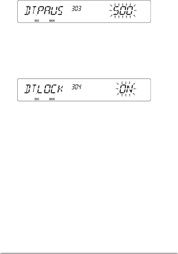
n Selecting a Transmit Speed
Some repeaters may not respond correctly if a DTMF number is transmitted
at fast speed. If this happens, change the DTMF number transmission speed
from FAST (default) to SLOW.
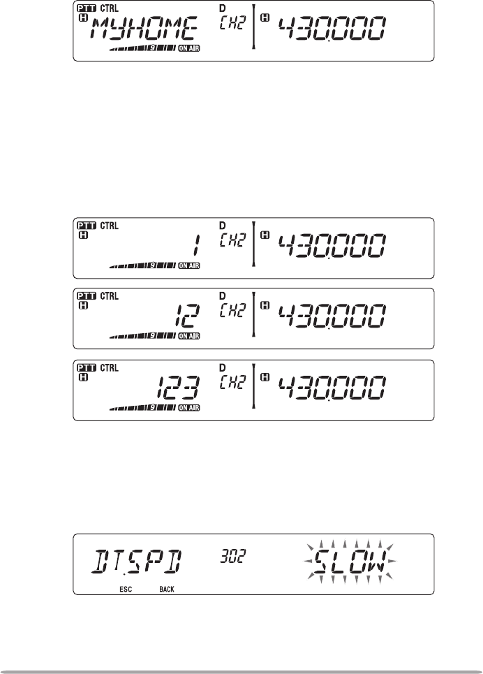
1 Enter Menu mode and access Menu 302 (DT.SPD) {page 20}.
2 Set the speed to FAST or SLOW.
58
n Selecting a Pause Duration
You can change the pause duration stored in DTMF Memory channels; the
default is 500 msec.
1 Enter Menu mode and access Menu 303 (DT.PAUS) {page 20}.
2 Select a speed (in msec) from the available list: 100/ 250/ 500/ 750/ 1000/
1500/ 2000.
DTMF KEY LOCK
This function will lock the DTMF transmission keys so that they will not transmit if
they are accidentally pressed. To lock the DTMF keys, turn this function ON.
1 Enter Menu mode and access Menu 304 (DT.LOCK) {page 20}.
2 Set the key lock to ON or OFF.
59
EchoLink MEMORY
AUTOMATIC DIALER
There are 10 dedicated EchoLink Memory channels available. You can store up
to 8 characters in each channel.
n Storing EchoLink Memory
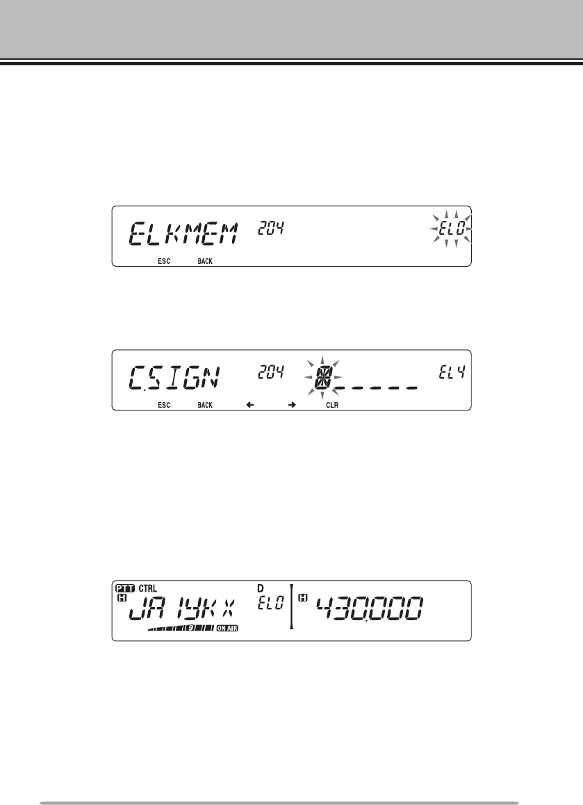
1 Enter Menu mode and access Menu 204 (ELK.MEM) {page 20}.
2 Rotate the Tuning control to select an EchoLink channel number from
EL0 ~ EL9.
3 Press the Tuning control to set the selected channel number.
• The call sign entry display appears.
4 Enter the call sign for the channel {page 24}, then press the Tuning control
to set it.
n Transmitting EchoLink Memory
1 Select the band and frequency of the node to which you want to connect.
2 Press and hold the microphone [PTT].
3 While transmitting, press the Tuning control.
• The last called Echolink/DTMF Memory channel name and number appears on
the display.
60
4 While still transmitting, rotate the Tuning control to select your desired
EchoLink Memory channel, then press the Tuning control to set the
channel.
• The stored code scrolls across the display and is transmitted.
• The code will be transmitted even if you release [PTT] before the entire code has
scrolled across the display.
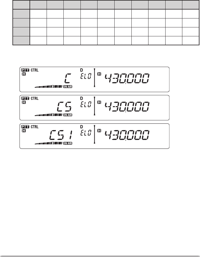
• The DTMF code of the changed Call Sign appears on the display. The Call Sign
code is automatically preceeded with a “C” and ends with a “#”. DTMF values
are listed in the following table:
1234567890
01234567890
1Q A D G J M P T W
2Z B E H K N R U X
3C F I L O S V Y
So, for example, if the Call Sign being transmitted was JA1YKX, the display
would read: C 51 21 10 93 52 92 #
• If no data is stored in the selected channel, the frequency display is restored.
61
n Selecting a Transmit Speed
Some repeaters may not respond correctly if a code is transmitted at fast
speed. If this happens, change the EchoLink transmission speed from FAST
(default) to SLOW.
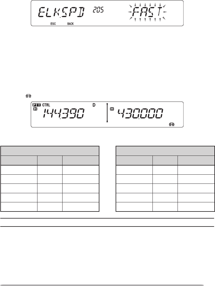
1 Enter Menu mode and access Menu 205 (ELK.SPD) {page 20}.
2 Set the speed to FAST or SLOW.
SETTING UP EchoLink MODE
When connected to a PC, you can set whether or not to use the RTS and CTS
terminals for hard ow control, or the SQC and PKS terminals for EchoLink.
1 Turn the transceiver power OFF.
2 Press [PF2] + Power ON to turn EchoLink ON.
• The icon appears on the display when EchoLink is ON.
• To turn EchoLink OFF, press [PF2] + Power ON again.
EchoLink Mode ON EchoLink Mode OFF
TM-V71 PC TM-V71 PC
TxD –> RxD TxD –> RxD
RxD <– TxD RxD <– TxD
SQC –> CTS RTS –> CTS
PKS <– RTS CTS <– RTS
GND <–> GND GND <–> GND
Note: When in EchoLink mode, you cannot change to Repeater mode or Remote Control mode.
62
AUXILIARY FUNCTIONS
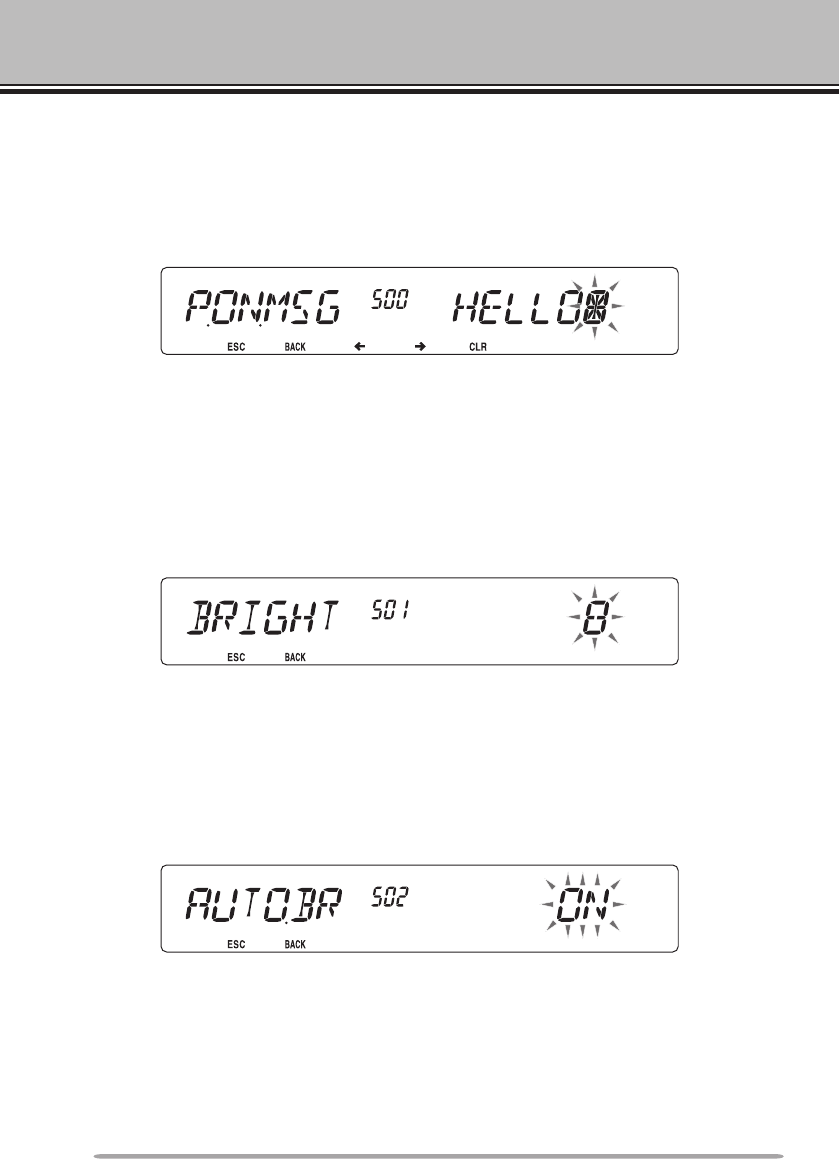
POWER-ON MESSAGE
Each time you switch the transceiver ON, “HELLO” (default) appears on the
display for approximately 2 seconds. You can program your favorite message in
place of the default message.
1 Enter Menu mode and access Menu 500 (P.ON.MSG) {page 20}.
2 Enter your desired message {page 24}.
• Press [PF1] (CLR) to clear the entire message, if necessary.
DISPLAY BRIGHTNESS
You can manually change the display illumination to suit the lighting conditions
where you are operating.
1 Enter Menu mode and access Menu 501 (BRIGHT) {page 20}.
2 Set your desired brightness level from 1 to 8, or OFF.
• Press [PF1] (CLR) to clear the entire message, if necessary.
n Auto Display Brightness
When Auto Brightness is activated, the display will light up every time a key is
pressed.
1 Enter Menu mode and access Menu 502 (AUTO.BR) {page 20}.
2 Set the Auto Brightness function to ON or OFF.
63
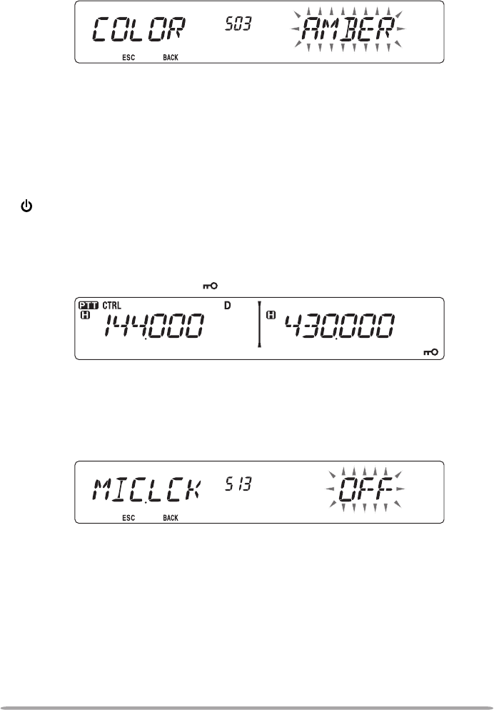
n Backlight Color
You can manually change the display illumination to suit the lighting conditions
where you are operating.
1 Enter Menu mode and access Menu 503 (COLOR) {page 20}.
2 Set the backlight color to AMBER or GREEN.
KEY LOCK
The Key Lock function ensures that your transceiver settings will remain
unchanged if you accidentally press a key. When activated, the following
functions can still be used:
• [ ]
• [PTT]
• microphone [PF]
To turn Key Lock ON or OFF, press [F] (1s).
• When Key Lock is activated, the icon will appear on the display.
n Microphone Key Lock
The Microphone Key Lock function will lock the microphone PF (Progammable
Function) keys.
1 Enter Menu mode and access Menu 513 (MIC.LCK) {page 20}.
2 Turn the Micrphone Key Lock function ON or OFF.
64
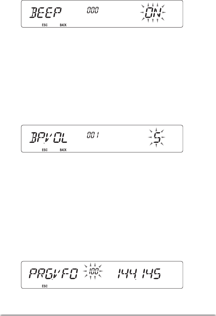
KEY BEEP
You can turn the transceiver beep function ON or OFF as desired.
1 Enter Menu mode and access Menu 000 (BEEP) {page 20}.
2 Turn the beep function ON or OFF.
• Even with the beep function turned OFF, the transceiver will emit a beep tone under
the following conditions:
1) When Auto Power Off is activated, the transceiver will beep 1 minute before the
power turns off.
2) After transmitting for the maximum time duration according to the Time-out Timer,
the transceiver will beep
n Beep Volume
Each time you press a key, the beep tone will sound. If you have left the beep
function turned ON, you may wish to adjust the volume level of the beep.
1 Enter Menu mode and access Menu 001 (BP.VOL) {page 20}.
2 Set the beep volume to a level from 1 to 7.
• The default is level 5.
PROGRAMMABLE VFO
If you always check frequencies within a certain range, you can set upper and
lower limits for frequencies that are selectable. For example, if you select 144
MHz for the lower limit and 145 MHz for the upper limit, the tunable range will be
from 145.000 MHz to 146.995 MHz.
1 Press the left or right [BAND SEL] to set band A or B as the operating band,
then press [VFO].
2 Enter Menu mode and access Menu 100 (PRG.VFO) {page 20}.
(Example: E type)
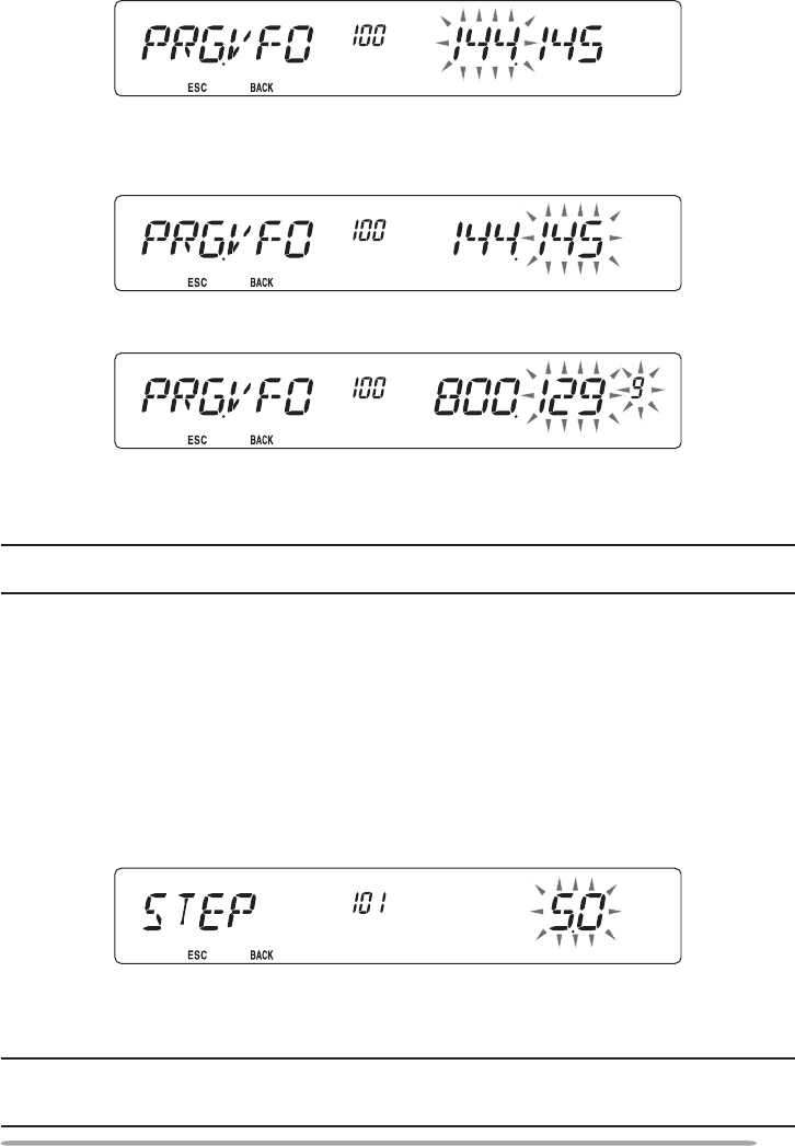
65
3 Press the Tuning control.
• The lower frequency limit blinks.
4 Rotate the Tuning control to select your desired lower frequency limit, then
press the Tuning control to set the selected value.
• The upper frequency limit blinks.
• When setting the limit for the 1200 MHz band, the 1 MHz digit appears on the
7-segment display to the right of the main display.
5 Rotate the Tuning control to select your desired upper frequency limit, then
press the Tuning control to set the selected value.
6 Press [CALL] (ESC) to exit Menu mode.
Note: You cannot program the 100 kHz and subsequent digits. The exact 100 kHz and
subsequent digits of the upper limit depend on the frequency step size you are using.
CHANGING THE FREQUENCY STEP SIZE
Choosing the correct frequency step size is essential in selecting your exact
frequency. The default step size on the 144 MHz band is 5 kHz (K type) or
12.5 kHz (E, M4 types). The default on the 430/440 MHz band is 25 kHz. For K
type models, the default on the 118, 220, or 300 MHz band is 12.5 kHz and the
default on the 1200 MHz band is 25 kHz.
1 Press the left or right [BAND SEL] to select band A or B, then press [VFO].
2 Enter Menu mode and access Menu 101 (STEP) {page 20}.
3 Set the step size to 5.0*, 6.25*, or 8.33 kHz (118 MHz band only) or to 10.0,
12.5*, 15.0, 20.0, 25.0, 30.0, 50.0, or 100.0 kHz.
*
These step sizes are not available for the 1200 MHz band.
Note: Changing between step sizes may correct the displayed frequency. For example, if
144.995 MHz is displayed with a 5 kHz step size selected, changing to a 12.5 kHz step size
corrects the displayed frequency to 144.9875 MHz.
66
PROGRAMMABLE FUNCTION KEYS
n Transceiver Front Panel
There are 2 PF (Programmable Function) keys on the transceiver front panel:
PF1 and PF2. You can assign your own desired functions to these 2 keys.
1 Enter Menu mode and access Menu 507 (PF1) and/or Menu 508 (PF2)
{page 20}.
2 Set your desired function for the key. Programmable functions available
are: WX CH (Weather Channel)/ FR.BAND/ CTRL (Control)/ MONI
(Monitor)/ VGS/ VOICE (Voice ON/OFF)/ GRP.UP/ MENU (Menu mode)/
MUTE (Speaker Mute)/ SHIFT (Shift)/ DUAL (Dual Mode)/ M>V (Memory to
VFO Copy)/ 1750 (1750 Hz Tone).
n Microphone Keys
There are 4 microphone PF (Programmable Function) keys: [PF] (PF1), [MR]
(PF2), [VF0] (PF3) and [CALL] (PF4). You can assign your own desired
functions to these 4 keys.
1 Enter Menu mode and access Menu 509 (MIC.PF1) and/or Menu 510
(MIC. PF2) and/or Menu 511 (MIC. PF2) and/or Menu 512 (MIC. PF2)
{page 20}.
2 Set your desired function for the key. Programmable functions available
are: WX CH (Weather Channel)/ FR.BAND/ CTRL (Control)/ MONI
(Monitor)/ VGS/ VOICE (Voice ON/OFF)/ GRP.UP/ MENU (Menu mode)/
MUTE (Speaker Mute)/ SHIFT (Shift)/ DUAL (Dual Mode)/ M>V (Memory to
VFO Copy)/ VFO/ MR/ CALL/ MHz/ TONE/ REV (Reverse)/ LOW/ LOCK/
A/B (Band Select A/ Band Select B)/ ENTER/ 1750 (1750 Hz Tone).
67
FREQUENCY DIRECT ENTRY
If the desired operating frequency is far from the current frequency, using the
microphone keypad is the quickest way to change the frequency. One of the
microphone PF keys must rst be programmed as ENTER {page 66},
1 Press the left or right [BAND SEL] to select band A or B, then press [VFO] or
[CALL].
2 Press the key programmed as [ENTER].
• The Direct Frequency Entry display appears.
3 Press the microphone keys ([0] ~ [9]) to enter your desired frequency.
4 To set the entered frequency, press [ENTER] or [VFO].
• Pressing [ENTER] before entering all of the digits will set the remaining digits to 0.
• Pressing [VFO] before entering all of the digits will leave the remaining digits at their
previous values.
• Entering all digits for a frequency will automatically set the frequency without
pressing [ENTER] or [VFO].
• If you need to only change the MHz digit, press the Tuning control, then enter the
new value.
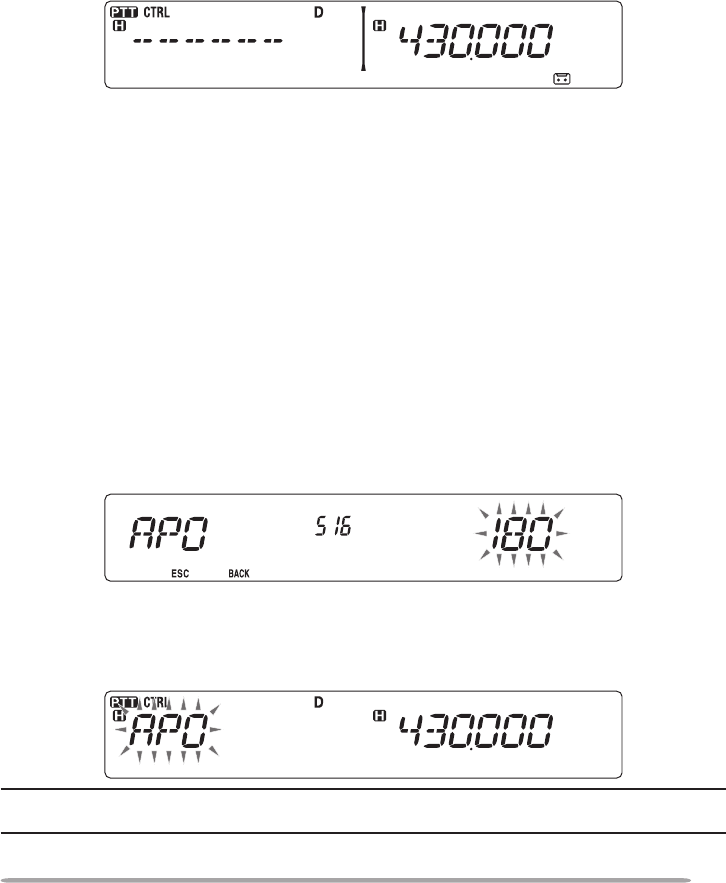
AUTOMATIC POWER OFF (APO)
Automatic Power Off is a background function that monitors whether or not any
operations have been performed (keys pressed, Tuning control turned, etc.), and
turns the transceiver power OFF if it has not been in use.
1 Enter Menu mode and access Menu 516 (APO) {page 20}.
2 Set the APO time limit to 30, 60, 90, 120, 180 minutes, or OFF.
• After the time limit passes with no operations (default is 180 minutes), APO turns
the transceiver power OFF. However, 1 minute before the power turns OFF, “APO”
appears on the display and blinks, and a warning tone sounds.
Note: If any settings are changed during while APO is ON, the timer resets. When you stop
changing the settings, the timer begins counting again from 0.
68
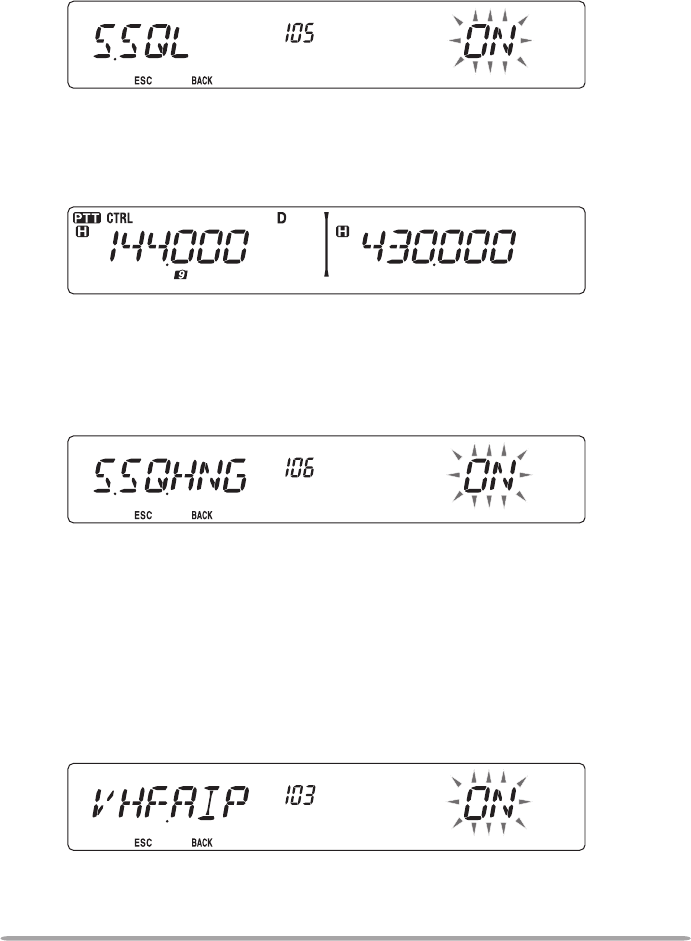
S-METER SQUELCH
S-meter Squelch causes the squelch to open only when a signal with the same or
greater strength than the S-meter setting is received. This function relieves you
from constantly resetting the squelch when receiving weak stations that you have
no interest in.
1 Enter Menu mode and access Menu 105 (S.SQL) {page 20}.
2 Set the S-Meter squelch to ON or OFF.
3 To select the desired S-meter setting, rotate the left (band A) or right (band B)
SQL control depending on which band you have selected.
• The squelch will open only at the level you have selected (for example, level 9).
n Squelch Hang Time
When using S-meter Squelch, you may want to adjust the time interval
between when the received signals drop and when the squelch closes.
1 Enter Menu mode and access Menu 106 (S.SQ.HNG) {page 20}.
2 Set the hang time to 125 or 500 ms, or OFF.
ADVANCED INTERCEPT POINT (AIP)
The VHF/UHF band is often crowded in urban areas. AIP helps eliminate
interference and reduce audio distortion caused by intermodulation. You can use
this function only while operating on the VHF/UHF band.
1 Enter Menu mode and access Menu 103 (VHF.AIP) and/or Menu 104
(UHF.AIP) {page 20}.
2 Set the AIP to ON or OFF.
69
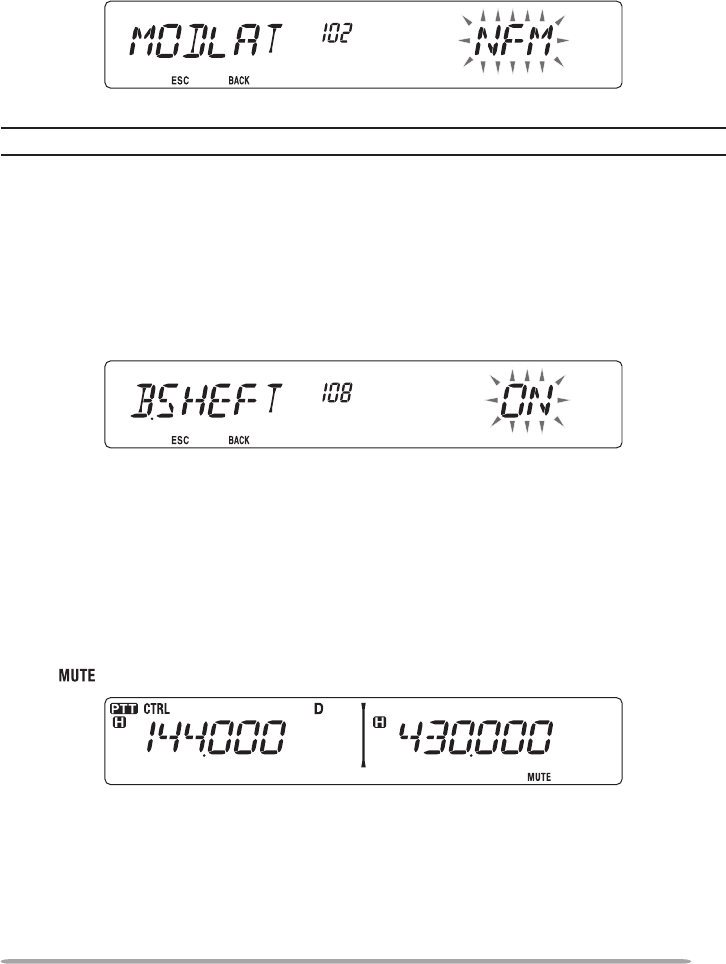
SWITCHING FM/AM MODE
This transceiver is also capable of receiving (not transmitting) in AM on band A.
The default mode on the 118 MHz band is AM while the default on the 144, 220,
300, or 430/440 MHz band is FM.
1 Enter Menu mode and access Menu 102 (MODLAT) {page 20}.
2 Set the mode to AM, FM, or NFM.
Note: You cannot switch between FM and AM to receive on band B.
BEAT SHIFT
Since the transceiver uses a microprocessor to control various transceiver
functions, the CPU clock oscillator’s harmonics or image may appear on some
spots of the reception frequencies. In this case, we recommend you turn the Beat
Shift function ON.
1 Enter Menu mode and access Menu 108 (B.SHIFT) {page 20}.
2 Set the Beat Shift to ON or OFF.
SPEAKER MUTE
While receiving or transmitting on the TX band, you may not want to hear audio
received on the other band. Use this function to mute the speaker allocated to
that band (not the TX band).
While receiving, press [LOW] to switch the mute function ON or OFF.
• The icon appears on the display when the function is ON.
70
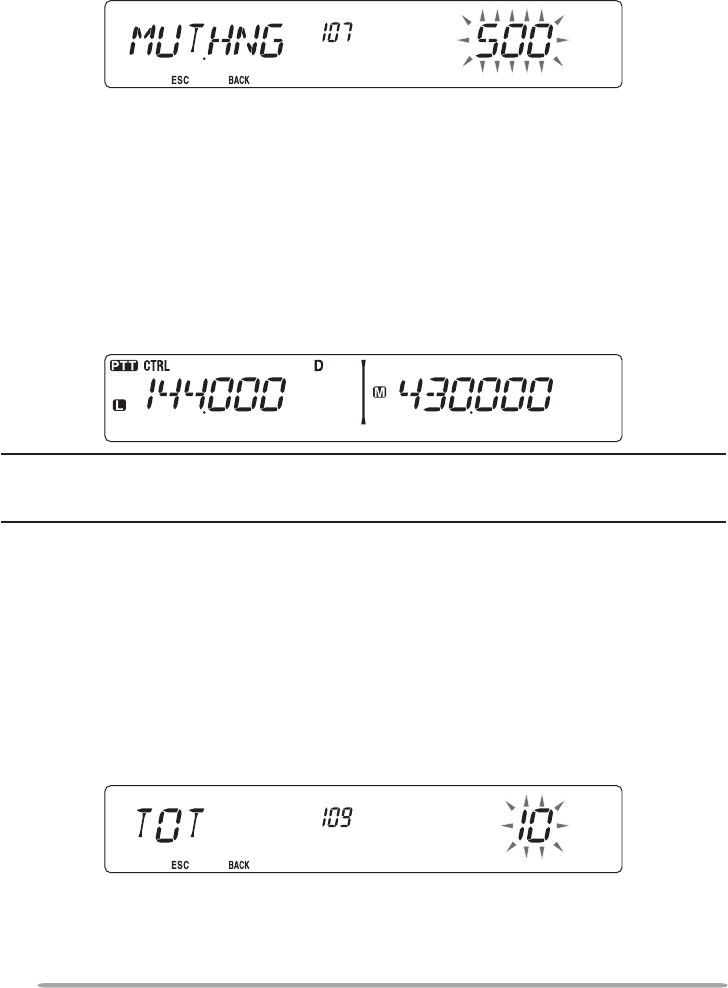
n Mute Hang Time
When using Speaker Mute, you may want to adjust the time interval between
when you receive a signal and when the speaker is muted.
1 Enter Menu mode and access Menu 107 (MUT.HNG) {page 20}.
2 Set the hang time to 125, 250, 500, 750, or 1000 ms.
SELECTING AN OUTPUT POWER
It is a good idea to select lower transmit power if communications is still reliable.
This lowers the risk of interfering with others on the band. When operating from
battery power, you will enjoy more operating time before a recharge is necessary.
Press [LOW] to select high (H) (K, E types only), medium (M), or low (L) power.
The default is high.
• You can program different power settings for bands A and B.
Note: When the transceiver overheats because of ambient high temperature or
continuous transmission, the protective circuit may function to lower transmit
output power.
TIME-OUT TIMER (TOT)
It is sometimes necessary or desirable to restrict a single transmission to a
specic maximum time. You may use this function to prevent repeater time-outs
when accessing repeaters, or to conserve battery power.
When TOT times out (default is 10 minutes), the transceiver generates beeps and
automatically returns to receive mode. To resume transmitting, release and then
press the microphone [PTT] again.
1 Enter Menu mode and access Menu 109 (TOT) {page 20}.
2 Set the timer to 3, 5, or 10 minutes.
71
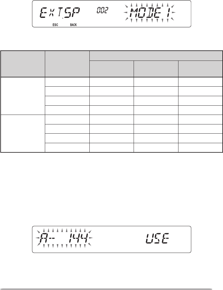
EXTERNAL SPEAKER CONFIGURATION
This transceiver has two speaker jacks for external speakers, as well as an
internal speaker. You can enjoy a variety of speaker congurations by using
one or two external speakers. Received signals on bands A and B are output
depending on how you want the internal and/or external speakers to function.
1 Enter Menu mode and access Menu 002 (EXT.SP) {page 20}.
2 Set the speaker mode to MODE 1 or MODE 2.
• Refer to the table below for congurations based on the mode selected.
Mode Speaker
Setup
Band Output
Internal
Speaker External SP1 External SP2
MODE 1
None A, B – –
SP1 only x A, B –
SP2 only A – B
SP1, SP2 x A B
MODE 2
None A, B – –
SP1 only x A, B –
SP2 only B – A
SP1, SP2 x B A
MASKING A BAND
If you have no plans to use band A or B, you can hide the frequency display on
the unused band. This saves power consumption and makes it simpler to read
the information you need.
1 Turn the transceiver power OFF.
2 Press the left or right [BAND SEL] + Power ON.
• The band mask display appears.
3 Rotate the Tuning control to select the band you want to hide (or return to
normal).
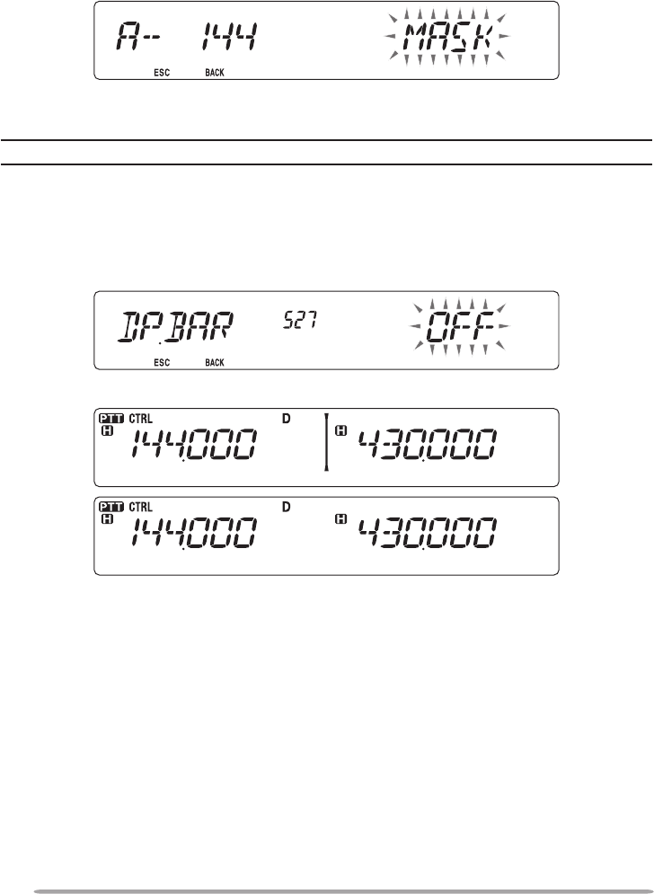
72
4 Press the Tuning control to set the selected band.
5 Rotate the Tuning control to set the band to select USE or MASK.
• USE allows you to see and use the band as normal. MASK hides the band on the
display.
6 Press the Tuning control to set the selection.
7 Press the [CALL] (ESC) to exit.
Note: You cannot operate the masked band nor use it to receive or transmit.
DISPLAY PARTITION BAR
The partition bar that appears between bands A and B can be removed if desired.
1 Enter Menu mode and access Menu 527 (DP.BAR) {page 20}.
2 Set the partition bar display to ON or OFF.
73
WEATHER ALERT (K TYPE MODELS ONLY)
The Wealther Alert is available only in the USA and Canada. When activated,
this function will check for a received NOAA 1050 Hz tone. When the tone is
received, the weather alert tone will sound.
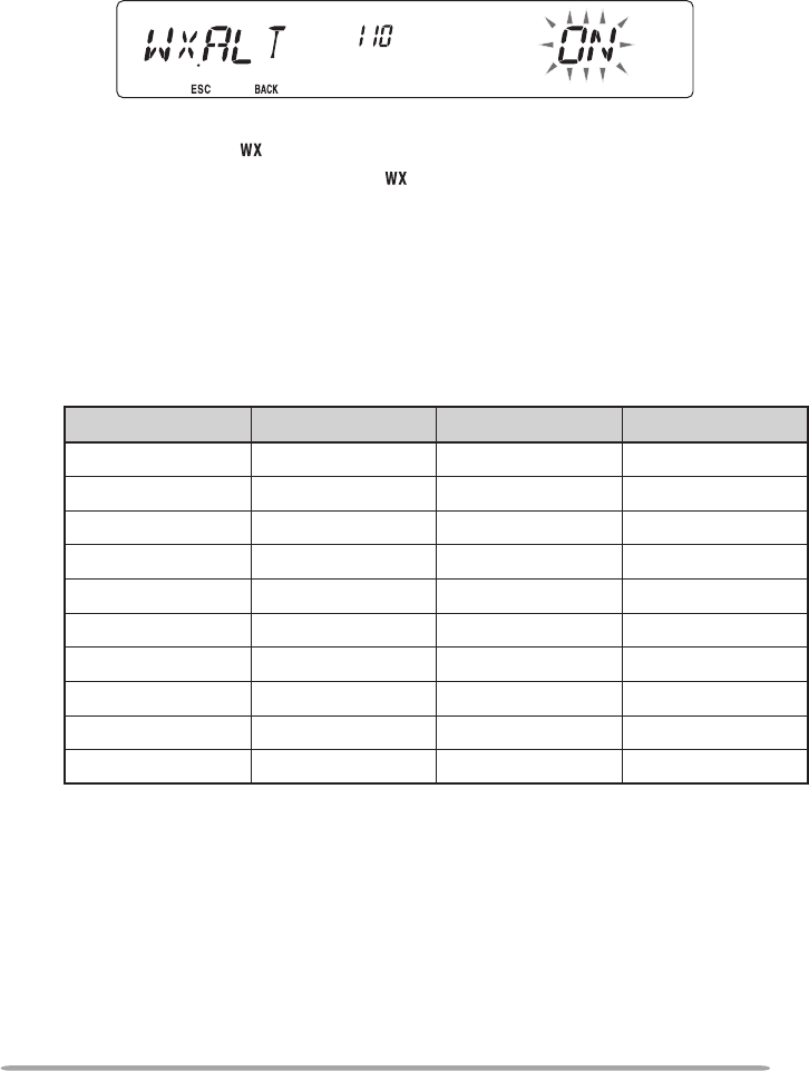
1 Enter Menu mode and access Menu 110 (WX.ALT) {page 20}.
2 Set the Weather Alert to ON or OFF.
• When activated, the icon appears on the display.
• When a signal is being received, the icon blinks.
n Weather Channel
Whether or not the Weather Alert is activated, you can still access the weather
channels. The Weather Alert simply noties you of activity on the weather
channels.
1 Press the key programmed with the WX function.
2 Rotate the Tuning control to select your desired channel.
Channel No.
Frequency (MHz)
Memory Name Location
A1 162.550 WX 1 NOAA/ Canada
A2 162.400 WX 2 NOAA/ Canada
A3 162.475 WX 3 NOAA/ Canada
A4 162.425 WX 4 NOAA
A5 162.450 WX 5 NOAA
A6 162.500 WX 6 NOAA
A7 162.525 WX 7 NOAA
A8 161.650 WX 8 Canada
A9 161.775 WX 9 Canada
A10 163.275 WX 10 –
74
PASSWORD PROTECTION
If password protection is activated, you cannot operate the transceiver without
rst entering your password, after turning the transceiver power ON. Your
password can be changed using the MCP control software.
The password can contain up to 6 digits. When using the front panel keys, you
can enter digits from 1 ~ 5. When using the microphone keypad, you can enter
digits from 0 ~ 9 and A ~ F.
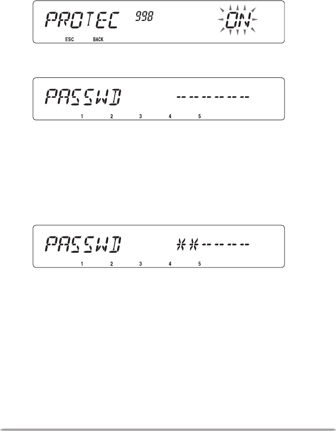
1 Enter Menu mode and access Menu 998 (PROTEC) {page 20}.
2 Set the password protection to ON or OFF.
• When set to ON, “PASSWD” appears on the display.
3 Enter your password using the microphone keypad or the transceiver front
panel keys.
• When using the transceiver front panel keys, they operate as follows:
[CALL]: 1
[F]: 2
[TONE]: 3
[REV]: 4
[LOW]: 5
4 After entering up to 6 digits, press the Tuning control to set the password.
75
VGS-1 OPTIONAL VOICE GUIDE & STORAGE UNIT
When using the optional VGS-1 voice guide & storage unit, you gain access to the
voice recorder and voice announcement functions.
VOICE ANNOUNCEMENTS
When changing modes, frequencies, settings, etc., an audio voice will announce the
new information.
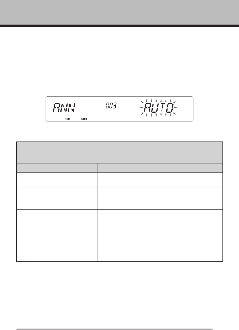
1 Enter Menu mode and access Menu 003 (ANN) {page 20}.
2 Set the announcement function to MANUAL, AUTO, or OFF.
• Refer to the tables below for announcements based on settings.
MANUAL:
A microphone PF key must be programmed as [VOICE] to use MANUAL voice
announcment.
Operation Announcement
While in VFO mode Press [VOICE]:
Operating band frequency
While in MR mode
Press [VOICE]:
“Channel” + Channel number + operating band
frequency
While in Call mode Press [VOICE]:
“Call channel” + operating band frequency
While in Menu mode
Press [VOICE]:
Menu number or setting value (some selections
have no voice announcement)
While setting up Tone/CTCSS/
DCS
Press [VOICE]:
Current frequency/code

76
AUTO:
Announcements are made automatically when changing a mode/frequency/setting.
Operation Announcement
Press [VFO] “VFO”
Press [MR] “MR”
Press [CALL] “Call”
Press [MENU] “Menu” + menu number
Press [PM] “PM”
Press [ENT] “Enter”
Change the operating band/
turn the power ON
“A”/“B” + “Channel” (for MR only) + “Call”/channel
number + “Channel (for CALL only) + operating
band frequency + output power level
Change the frequency band New receive frequency
Setting up the PM Channel number/“Off”
Frequency direct entry Entered key number
Memory Direct Entry mode Channel number
Press [F] in VFO mode “Memory in” + channel number + frequency
Press [F], [M.IN] in VFO mode “Memory in” + channel number + “Blank”
Press [A/B] in VFO mode “A”/“B” + frequency + output power level
Press [F] and then the Tuning
control in VFO mode “Menu” + menu number
Press the Tuning control in
Menu mode Setting value
Perform a Full Reset “Full reset?”
Perform a Partial Reset “Partial reset?”
Perform a VFO Reset “VFO reset?”
Perform a PM Reset “PM reset?”
Press [LOCK] (to turn the Lock
function ON) “Lock on”
Press [LOCK] (to turn the Lock
function OFF) “Lock off”
Tone frequency setup “Tone frequency” + frequency value
CTCSS frequency setup “CTCSS frequency” + frequency value
DCS code setup “DCS” + code value
MHz step frequency setup “MHz Step” + frequency value
10 MHz setup “10” + “MHz setup” + frequency value
Output power setup “TX Power” + power level
77
■ Voice Announcement Language
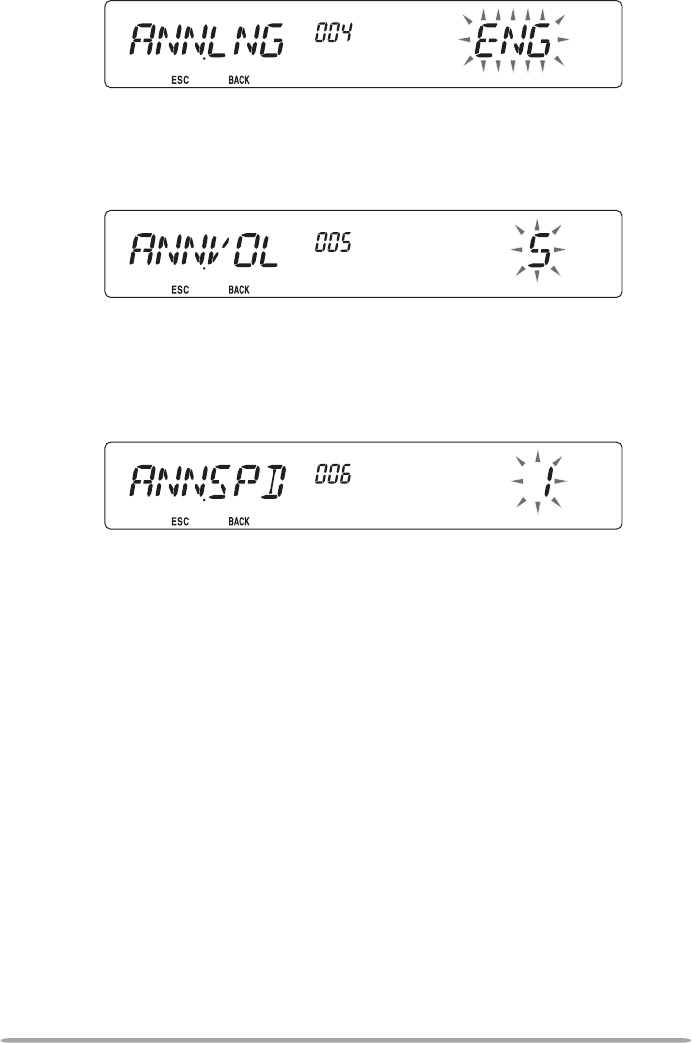
1 Enter Menu mode and access Menu 004 (ANN.LNG) {page 20}.
2 Set the language to ENG (English) or JPN (Japanese).
■ Voice Announcement Volume
1 Enter Menu mode and access Menu 005 (ANN.VOL) {page 20}.
2 Set the announcement volume level from 1 to 7.
• To turn the volume OFF, turn the announcement function OFF.
■ Voice Announcement Speed
1 Enter Menu mode and access Menu 006 (ANN.SPD) {page 20}.
2 Set the announcement speed level from 0 to 4.
• The speed settings are as follows:
0: 0.85 times normal speed
1: Normal speed
2: 1.15 times normal speed
3: 1.30 times normal speed
4: 1.45 times normal speed
78
VOICE RECORDER
The voice recorder provides you with 3 VGS channels for recording voice memos,
along with a single VGS channel for recording conversations. You can also
prepare automated message responses to received calls.
Each recording can last for up to 30 seconds.
■ Voice Memos
To record a voice memo, for later playback:
1 Press the PF key programmed as [VGS].
2 Press and hold the key for the VGS channel number you want to store the
memo in: [F] (1), [TONE] (2), or [REV] (3).
• A beep will sound and the transceiver will enter Recording mode.
3 Press and hold the VGS channel number key again (the same key you
pressed in the previous step), then speak into the microphone to record
your memo.
• Recording begins as soon as you press the VGS channel number key, and a
timer appears on the display.
• Pressing the microphone PTT switch at this time will transmit your message as
well as record it. Do not press the microphone PTT switch if you do not want to
transmit your message.
4 Release the VGS channel number key to end the recording at any time and
store it into the selected VGS channel.
• If the memory becomes full, recording will stop automatically and store the voice
memo to memory.
• “WRITING” appears on the display while the recording is being stored to
memory.
79
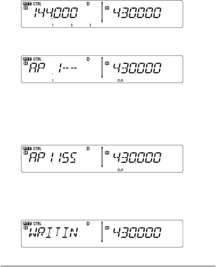
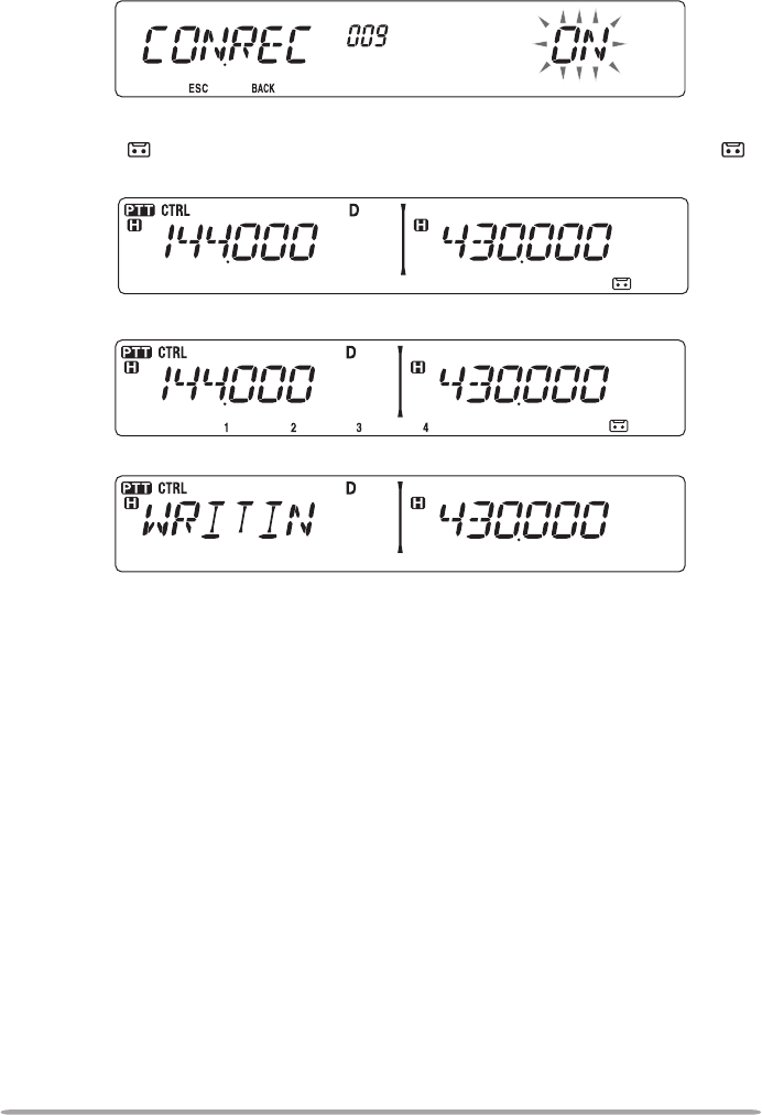
■ Conversation Recorder
To record a 30 second conversation:
1 Enter Menu mode and access Menu 009 (CON.REC) {page 20}.
2 Set the Conversation Recorder to ON (or OFF).
• The icon appears on the display when this function is activated. The icon
does not appear during playback, in Repeater mode, or in Remote Control mode.
3 Press the PF key programmed as [VGS].
4 Press [LOW] (4) (1s) to store the conversation in VGS channel 4.
80
■ Playback
1 Press the PF key programmed as [VGS].
2 Press the key for the VGS channel number you want to play back: [F] (1),
[TONE] (2), [REV] (3), or [LOW] (4).
• The recording saved in the channel you selected is played back.
• To end playback at any time, press [PF1] (CLR).
• To exit, press [VGS] again.
• During playback, you can switch to any of recordings 1, 2, or 3 by pressing the
appropriate key.
• While playing a recording, you can transmit the recording by pressing the
[PTT] switch. (Continue holding the [PTT] switch until the entire recording is
transmitted.)
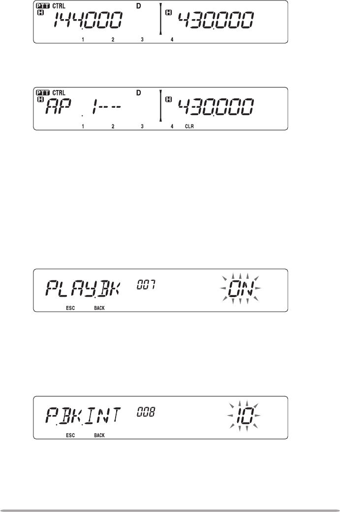
■ Playback Repeat
You can set messages to be repeatedly played back.
1 Enter Menu mode and access Menu 007 (PLAY.BK) {page 20}.
2 Set the the Playback Repeat function to ON or OFF.
■ Playback Repeat Interval
If the Playback Repeat function is activated, you can set a time interval for how
often the memo/message is played back.
1 Enter Menu mode and access Menu 008 (P.BK.INT) {page 20}.
2 Set the interval from 0 to 60 seconds.
81
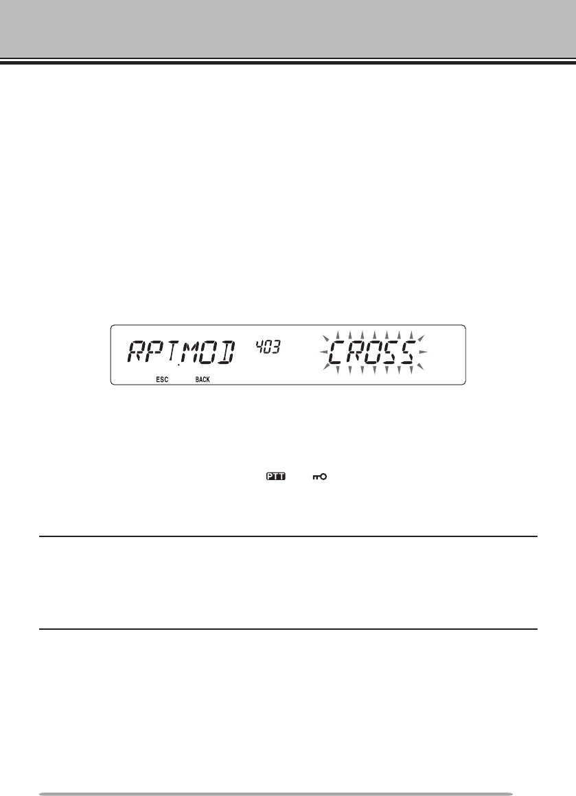
CROSS-BAND/ LOCKED-BAND OPERATION (K TYPE MODELS ONLY)
This transceiver is capable of receiving signals on one band and retransmitting
signals on the other band. This function repeats signals originating from one
band, using the other band. For example, a signal received on band A (VHF) is
retransmitted on band B (UHF). Similarly, a signal received on band B (UHF) is
retransmitted on band A (VHF).
Locked-band Repeater: The transceiver uses the same band to receive or
transmit a signal. You can set either the A band (A-TX) or B band (B-TX) as the
transmit band.
Cross-band Repeater: If receiving a signal on the TX band, the transceiver
switches the current RX only band to the TX band. This is useful when joining
in a group talk. Participants in a group talk need to set a receive and transmit
frequency on different bands so as not to miss any conversation within the group.
1 Enter Menu mode and access Menu 403 (RPT.MOD) {page 20}.
2 Set the Repeater operation mode to CROSS (cross-band), A-TX (A band), or
B-TX (B band).
3 Turn the transceiver power OFF.
4 Press [TONE] + Power ON.
• The Repeater mode is ON and the and icons blink on the display.
• You are unable to perform any transceiver functions while in Repeater mode.
• To return to normal operation, turn the transceiver power OFF, then press [TONE] +
Power ON.
Note:
u You cannot activate the Repeater function while in single band operating mode or Weather
Channel mode.
u Activating the Repeater function switches OFF the Automatic Simplex Checker (ASC).
u The Time-Out Timer is locked at 3 minutes.
u Resetting the transceiver {page 88} will not cancel the Repeater mode.
82
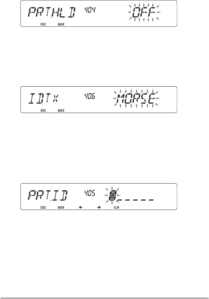
REPEATER HOLD
If necessary, you can set the transceiver to remain in the transmit mode for
500 ms after a signal drops.
1 Enter Menu mode and access Menu 404 (RPT.HLD) {page 20}.
2 Set the Repeater Hold function to ON or OFF.
REPEATER ID
If necessary, you can set the transceiver to transmit your call sign every 10
minutes.
1 Enter Menu mode and access Menu 406 (ID.TX) {page 20}.
2 Set the ID Trasmit function to OFF, MORSE, or VOICE.
• To use VOICE transmission, you must have the VGS-1 option installed. When using
the VGS-1 option, the ID Transmit function will use VGS channel 3 as the call sign
{page 78}.
• When selecting MORSE, the call sign stored in Menu 405 {see below} will be
transmitted at 20 wpm (words per minute).
n Entering your Repeater ID
1 Enter Menu mode and access Menu 405 (RPT.ID) {page 20}.
2 Enter your call sign {page 24}.
83
PACKET OPERATION
Connect this transceiver to your personal computer via a Terminal Node
Controller (TNC). You can send messages or commands to far away stations,
obtain a variety of information via your local bulletin boards, or enjoy other Packet
applications. Reference material for starting Packet operation should be available
at any store that handles Amateur Radio equipment.
Note:
u When the distance between the radio antenna and your personal computer is too close,
interference may occur.
u Do not share a power source between the transceiver and the TNC. When the distance
between the TNC and your personal computer is too close, interference may occur.
Data terminal pins:
No. Name I/O Function
qPKD Input Audio signal for packet transmission
wDE — PKD terminal ground
ePKS Input ‘L’ is transmitted and the microphone is muted
rPR9 Output 9600(bps) repeat signal
tPR1 Output 1200(bps) repeat signal
ySQC Output Squelch control signal; Closed: ‘L’, Open: ‘H’
E — Common ground
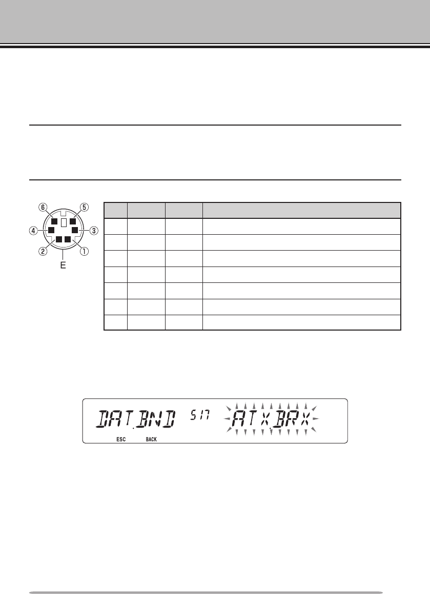
DATA BAND
Select how data will be transmited and received on your transceiver.
1 Enter Menu mode and access Menu 517 (DAT.BND) {page 20}.
2 Set the data band to A (A band receives and transmits), B (B band receives and
transmits), ATX.BRX (A band transmits and B band receives), or ARX.BTX (A
band receives and B band transmits).
DATA TERmINAl SPEED
Select 1200 or 9600 bps for the data transfer rate, depending on your TNC.
1200 bps: The transmit data input (PKD) sensitivity is 40 mVp-p, and the input impedance
is 10 kΩ.
9600 bps: The transmit data input (PKD) sensitivity is 2 Vp-p, the input impedance is
10 kΩ, and the TNC has dual speed capability with a 2 Vp-p output.
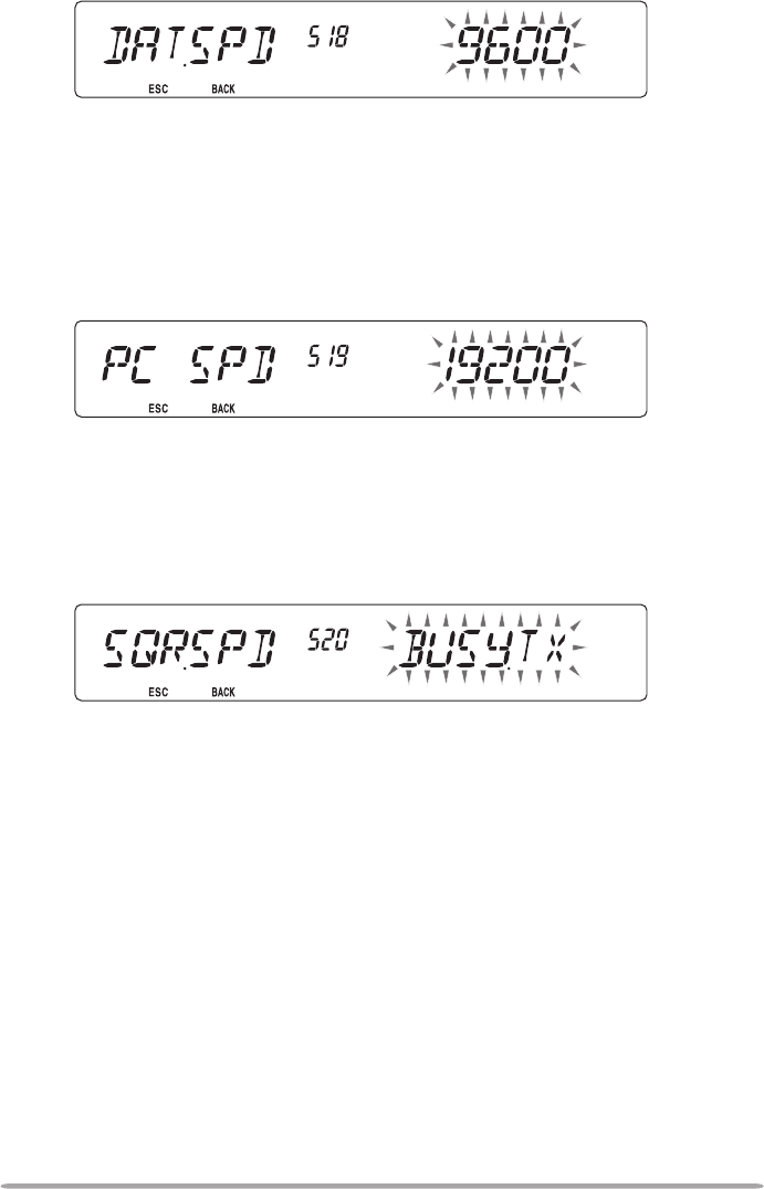
84
1 Enter Menu mode and access Menu 518 (DAT.SPD) {page 20}.
2 Set the data speed to 1200 or 9600 bps.
PC PORT SPEED
You can adjust the speed at which the computer and transceiver exchange
information, when the transceiver is connected to your computer.
1 Enter Menu mode and access Menu 519 (PC .SPD) {page 20}.
2 Set the PC port speed to 9600, 19200, 38400, or 57600 bps.
SQC OuTPuT SETTINg
You can set the condition for which the SQC output terminal becomes active.
1 Enter Menu mode and access Menu 520 (SQC.SRC) {page xx}.
2 Set the SQC output activation method to one of the following:
• OFF: SQC output remains inactive.
• BUSY: When a signal is received on the data band, the SQC output becomes active.
• SQL: While CTCSS/DCS is ON and a matching signal is received, the SQC output
becomes active. While CTCSS/DCS is OFF, the SQC output becomes active when
a busy signal is received.
• TX: While transmitting, the SQC output becomes active.
• BUSY.TX: When the conditions of BUSY and TX (above) are met, the SQC output
becomes active.
• SQL.TX: When the conditions of SQL and TX (above) are met, the SQC output
becomes active.
85
WIRELESS OPERATION (K TYPE MODELS ONLY)
If you also have a compatible Kenwood handy transceiver, you may use it as a
remote control for this mobile transceiver. You will control one band on the mobile
while sending DTMF tones to the other band from the handheld. This function is
useful, for example, when you want to control the mobile from a location outside
your vehicle.
Note:
u As a remote control, you can also use a handy transceiver which does not have a remote
control function but a DTMF function. However, you must manually send DTMF tones for
control code strings. Skip steps 1 and 3 in “PREPARATION”.
u The FCC rules permit you to send control codes only on the 440 MHz band.
PREPARATION
Let us assume band A (VHF) of the mobile transceiver will be controlled.
On the handy transceiver:
1 Program a 3-digit secret number.
• For the programming method, see the instruction manual for the handheld.
2 Select the transmit frequency on the UHF band.
3 Make the handheld enter Remote Control mode.
• For the method, see the instruction manual for the handheld. If not described,
consult your dealer.
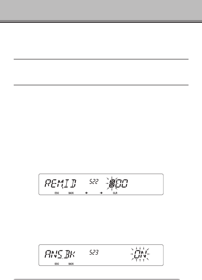
On the mobile transceiver:
4 Enter Menu mode and access Menu 522 (REM.ID) {page 20}.
5 Set the ID code to the same secret number you set on the handy transceiver.
6 Select the receive frequency on band B (UHF).
• Match this frequency with the transmit frequency on the handheld.
7 Select band A (VHF) as the TX band or Control band.
8 To cause the mobile to send a control acknowledgment to the handheld, enter
Menu 523 (ANS.BK) and set it to ON.
• DTMF tones which represent the secret number will be used as an acknowledgment.
9 Turn the transceiver power OFF.
86
10 Press [REV] + Power ON to enter Remote Control mode.
• The and icons appear on the display.
• To exit Remote Control operation, turn the transceiver power OFF, then press [REV]
+ Power ON again.
CONTROL OPERATION
While in Remote Control mode, the DTMF keys of the handheld will function as
shown in the table below. Each time you press the desired key, the handheld will
automatically enter transmit mode and send the corresponding command to the
mobile.
Operation DTMF Command
Access your mobile via the remote unit (where *** is your
3-digit secret number) A *** #
End access of your mobile via the remote unit A #
DCS ON 1
Tone ON 2
CTCSS ON 3
DCS OFF (all signalling OFF) 4
Tone OFF (all signalling OFF) 5
CTCSS OFF (all signalling OFF) 6
Call mode ON 7
VFO mode ON 8
Memory mode ON 9
Transmit power (press to toggle between High, Medium, and
Low) 0
Frequency (in VFO mode) or Memory channel (in Memory
mode) directy entry A XXXXXXX
DCS code (when DCS is ON), Tone frequency (when Tone is
ON), or CTCSS frequency (when CTCSS is ON) setup B XXX
Repeater (Cross-band or Locked-band) ON C
Repeater OFF D
Step the frequency or Memory channel down
Step the frequency or Memory channel up #
87
TRANSCEIVER RESET
There are 4 types of transceiver reset available:
VFO Reset
Use to initialize the VFO and accompanying settings.
PART (Partial) Reset
Use to initialize all settings other than the Memory channels, the DTMF memory,
and the PM channels.
PM Reset
Use to reset only the Programmable Memory channels to their default values.
FULL Reset
Use to initialize all transceiver settings that you have customized.
There are 2 ways to perform a reset on the transceiver: by key operation and by
accessing Menu mode.
Key Operation:
1 Turn the transceiver power OFF.
2 Press [F] + Power ON.
3 Rotate the Tuning control and select your desired reset type: VFO, PART,
PM, or FULL.
4 Press the Tuning control to set the reset type.
• Aconrmationmessageappearsonthedisplay.
• Press [TONE] (BACK) to return to the previous display or [F] (ESC) to cancel the
reset.
5 Press the Tuning control again to perform the reset.
Note: When in Remote Control or Repeater mode, you cannot reset the transceiver using the Key
Operation method.
88
Menu Mode:
1 Enter Menu mode and access Menu 999 (RESET) {page 20}.
2 Set the reset type to VFO, PART, PM, or FULL.
3 Press the Tuning control to set the reset type.
• Aconrmationmessageappearsonthedisplay.
• Press [TONE] (BACK) to return to the previous display or [F] (ESC) to cancel the
reset.
4 Press the Tuning control again to perform the reset.
Note: When the Channel Display function or Key Lock function is ON, the transceiver reset cannot
be performed.

89
OPTIONS
The following options are available for use with this transceiver:
• DFK-3D Detachable Front Panel Kit
• MC-45 Microphone
• MC-59 Microphone with keypad
• MCP-2A MCP (web download software)
• MJ-88 Microphone Plug Adapter
• MJ-89 Modular Plug Microphone Switch
• PG-2N DC Cable
• PG-20 DC Cable (7m)
• PG-3B Noise Filter
• PG-5A Data Cable
• PG-5G Programming Interface Cable
• PG-5H PC Interface Cable Kit
• PG-5F Extension Cable Kit
• PS-33 DC Power Supply
• PS-53 DC Power Supply
• SP-50B External Speaker
• VGS-1 Voice Guide & Storage Unit
Note: Optional accessories for use with this transceiver may change, post-production. (New
options may become available and/or current options may be discontinued.) Please refer to the
options catalog(s) for applicable transceivers.
90
CONNECTING THE PG-5G/ PG-5H INTERFACE CABLES
The PG-5G package comes with cable w (below).
The PG-5H packages comes with cables q and w (below).
q Data communications cable
w Serial communications cable
To external
TNC or other
equipment
To PC 9-pin
D-SUB terminal
INSTALLING THE DFK-3D PANEL KIT
n Installing the Sub-Panel
Data communications cable pin conguration
Serial communications cable pin conguration
(pink)
(green)
1 Detach the front operation panel from the
base unit, then remove the modular cable
from both sides.
2 Connect the 4-pin connector of the supplied
modular cable to the operation panel.
• Align the cable with the cable guide.
cable guide
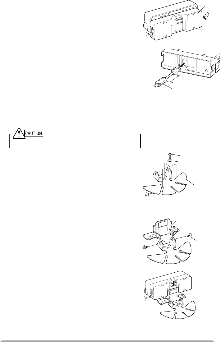
91
3 Connect the supplied sub-panel to the
operation panel.
• Install the sub-panel in a manner so as not to
disrupt the cable.
4 Connect the 8-pin connector of the supplied
modular cable to the base unit.
• The line lter is pre-installed onto the cable.
n Installing the Panel Bracket
1 Clean and dry the installation location.
Do not install the bracket close to an air bag.
2 Remove the release paper from the base
of the panel bracket, then secure it in place
using the 3 supplied self-tapping screws.
• Allow the panel to set for a while, to ensure it
remains fast. Otherwise, vibrations may occur.
• After removing the release paper, it cannot be
reused.
3 Attach the panel holder to the base bracket
using the 2 supplied SEMS screws.
4 Attach the operation panel to the panel
holder so that it locks in place.
sub-panel
Approx. 3 cm
line lter
panel bracket
Release paper
self-tapping screw
at washer
panel holder
SEMS screw
92
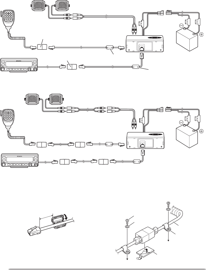
CONNECTING THE PG-5F EXTENSION CABLE
If necessary, the PG-5F extension cable kit can be used with the DFK-3D panel
kit. Using two PG-5F kits, you can extend the cables to the maximum length.
(Components marked with an asterisk * are included in the PG-5F kit.)
n Connecting Using a Single Extension Kit
n Connecting Using Two Extension Kits
microphone external speakers
operation panel
speaker cables (4 m)
* DC power cables (6 m)
* extension
connector
* extension
connector base unit
* modular cable (4 m)
* modular cable (4 m)
* line lter
* line lter
microphone
external speakers
operation panel
speaker cables (4 m) * DC power cables (6 m)
base unit
modular cable (4 m) &
extension connector (2 sets)
modular cable (4 m) &
extension connector (2 sets)
n Installing the Line Filter
Install the line lter approximately
3 cm from the connector which
attaches to the base unit.
n Affixing the Microphone Cable
Lock the microphone cable down
as shown in the illustration.
Approx. 3 cm self-tapping screw
at washer microphone
cable
cable holder
cushion
93
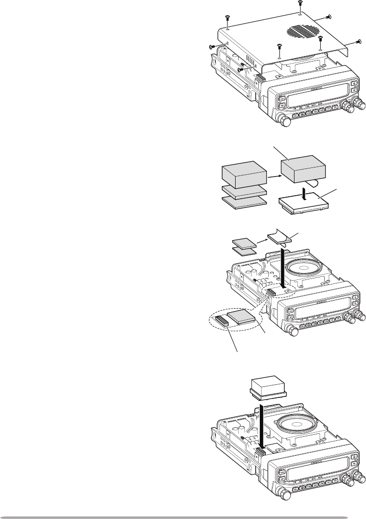
InstallIng the Vgs-1 VoIce guIde unIt
Follow the instructions below to install the VGS-1 unit.
cushion
connector
1 Remove the 8 screws from the cover of
the base unit, then remove the cover itself
from the unit.
2 From the 5 black cushions supplied with
the VGS-1, select the thickest rectangular
cushion (20 x 30 x 12 mm) and attach it to
the top surface of the VGS-1 unit.
• To prevent interferece to the terminal of the
VGS-1, ensure that you attach the thick
square cushion to the baseplate surface.
3 From the remaining cushions, select the
thickest square cushion (21 x 21 x 2.5
mm) and attach it to the printed circuit
board.
• The remaining cushions are not used
with this transceiver.
• Ensure that the cushion is placed within the
guidelines on the PCB.
4 Insert the VGS-1 unit into the connector
on the transceiver.
• Press down on the top of the VGS-1 unit
to ensure that it is securely attached to the
connector.
5 Replace the cover on the base unit and
secure it using the 8 screws.
VGS-1
cushion
guidelines
94
MAINTENANCE
GENERAL INFORMATION
This product has been factory aligned and tested to specication before shipment.
Attempting service or alignment without factory authorization can void the product
warranty.
SERVICE
When returning this product to your dealer or service center for repair, pack it in
its original box and packing material. Include a full description of the problem(s)
experienced. Include your telephone number along with your name and address
in case the service technician needs to contact you; if available, also include your
fax number and e-mail address. Don’t return accessory items unless you feel
they are directly related to the service problem.
You may return this product for service to the authorized Kenwood dealer from
whom you purchased it, or any authorized Kenwood service center. Please do
not send subassemblies or printed circuit boards; send the complete product. A
copy of the service report will be returned with the product.
SERVICE NOTE
If you desire to correspond on a technical or operational problem, please make
your note legible, short, complete, and to the point. Help us help you by providing
the following:
• Model and serial number of equipment
• Question or problem you are having
• Other equipment in your station pertaining to the problem
Do not pack the equipment in crushed newspapers for shipment! Extensive damage may result
during rough handling or shipping.
Note:
u Record the date of purchase, serial number and dealer from whom this product was purchased.
u For your own information, retain a written record of any maintenance performed on this
product.
u When claiming warranty service, please include a photocopy of the bill of sale or other
proof-of-purchase showing the date of sale.
CLEANING
To clean the case of this product, use a neutral detergent (no strong chemicals)
and a damp cloth.

95
TROUBLESHOOTING
The problems described in this table are commonly encountered operational
malfunctions and are usually not caused by circuit failure.
Problem Probable Cause Corrective Action
The transceiver will
not power up after
connecting a 13.8 V
DC power supply and
pressing [ ]. Nothing
appears on the display.
1 The power cable
was connected
backwards.
2 One or more of the
power cable fuses
are open.
1 Connect the supplied DC
power cable correctly (red
to + terminal and black to
– terminal).
2 Look for the cause of
the blown fuse(s). After
inspecting and correcting
any problems, install a
new fuse(s) with the same
ratings.
The frequency cannot
be selected by turning
the Tuning control or
by pressing microphone
[UP]/[DWN].
Memory Recall was
selected.
Press [VFO].
Most keys and the
Tuning control do not
function.
1 One of the Lock
functions is ON.
2 The transceiver is
in Channel Display
mode.
1 Unlock all of the Lock
functions.
2 With the transceiver
power OFF, press [REV] +
Power ON to exit Channel
Display mode.
Memory channels
cannot be selected
by turning the Tuning
control or by pressing
microphone
[UP]/[DWN].
No data has been stored
in any Memory channel.
Store data in some Memory
channels.
You cannot transmit
even though you are
pressing [PTT].
1 The microphone plug
was not inserted
completely into the
transceiver.
2 You selected a
transmit offset that
places the transmit
frequency outside the
allowable range.
3 The external TNC is
transmitting.
1 Switch the power OFF,
then insert the microphone
plug until the locking tab
clicks in place.
2 Turn the offset shift
function OFF.
3 Press [PTT] after the TNC
has nished transmitting.
96
SPECIFICATIONS
Specications are subject to change without notice due to advancements in
technology.
General K Type E Type M4 Type
Guaranteed
range
VHF
Band A
TX & RX
144 ~ 148 MHz
144 ~ 146 MHz
UHF
Band B
TX & RX
438 ~ 450 MHz
430 ~ 440 MHz
Frequency
range
Band A
TX 144 ~ 148 MHz —
RX 118 ~ 200 MHz —
TX (sub UHF)
438 ~ 450 MHz —
RX (sub UHF)
300 ~ 470 MHz —
RX 200 ~ 300 MHz —
Band B
TX 438 ~ 450 MHz —
RX 300 ~ 524 MHz —
TX (sub UHF)
144 ~ 148 MHz —
RX (sub UHF)
136 ~ 175 MHz —
RX 800 ~ 1300 MHz
(excluding cellular band) —
Mode F2D/ F3E
Antenna impedance 50 Ω
Operating temperature range –20°C ~ +60°C (–4°F ~ +140°F)
Power requirement 13.8 V DC ±15% (Negative ground)
Frequency stability Within ±5 ppm
Current TX
VHF
Hi Less than 11.5 A
Mid Less than 5.0 A
Low
Less than 4.0 A
UHF
Hi Less than 10.0 A
Mid Less than 6.0 A
Low
Less than 5.0 A
RX Less than 5.0 A
Dimensions
(W x H x D)
Without projections Panel: 140 x 43 x 38.2 mm (5.51" x 1.69" x 1.50")
Body: 140 x 43 x 180.7 mm (5.51" x 1.69" x 7.11")
With projections Panel: 140 x 43 x 55.4 mm (5.51" x 1.69" x 2.18")
Body: 140 x 43 x 213.1 mm (5.51" x 1.69" x 8.39")
Weight (approx.) 1.5 kg (3.3 lbs)
97
Transmitter K Type E Type M4 Type
RF power
output
Hi
50 W
—
Mid
Approx. 10 W
25W
Low Approx. 5 W
Modulation Reactance modulation
Maximum frequency deviation Within ±5 kHz
Spurious radiation Less than –60 dB
Modulation distortion
(300 Hz ~ 3 kHz) Less than 3%
Microphone impedance 600 Ω
Receiver K Type E Type M4 Type
Circuitry Double super heterodyne
Intermediate
frequency
1st (A band/ B band) 45.05 MHz/ 49.95 MHz
2nd (A band/ B band) 455 kHz/ 450 kHz
Sensitivity Less than 0.16 V
Squelch sensitivity Less than 0.1 V
Selectivity –6 dB More than 12 kHz
–40 dB Less than 28 kHz
Low frequency output (8 Ω) More than 2 W (at 5% distortion)
Note: Receiver specications apply only when using the main VHF or UHF band. They do not
apply to the sub VHF or UHF band.
Concerning the received frequency display, an unmodulated signal may be
received. This is according to the set intrinsic frequency form.
<A band> <B band>
VxU reception
(144 MHz + 45.05 MHz) x 2
–(430 MHz - 49.95 MHz) =
45.05 MHz, 49.95 MHz
(144 MHz + 45.05 MHz) x 4
–
(430 MHz - 49.95 MHz) x 2
=
45.05 MHz, 49.95 MHz
UxV reception
(430 MHz - 45.05 MHz) –
(144 MHz + 49.95 MHz) x 2
=
45.05 MHz, 49.95 MHz
(430 MHz - 45.05 MHz) x 2
–
(144 MHz + 49.95 MHz) x 4
=
45.05 MHz, 49.95 MHz