JVC KENWOOD 397700 144/440MHz FM Dual Bander User Manual User Instructions Guide
JVC KENWOOD Corporation 144/440MHz FM Dual Bander User Instructions Guide
Contents
- 1. Instruction Manual 1
- 2. Instruction Manual 2
- 3. User Manual
- 4. User Instructions Guide
- 5. User Guide Instructions
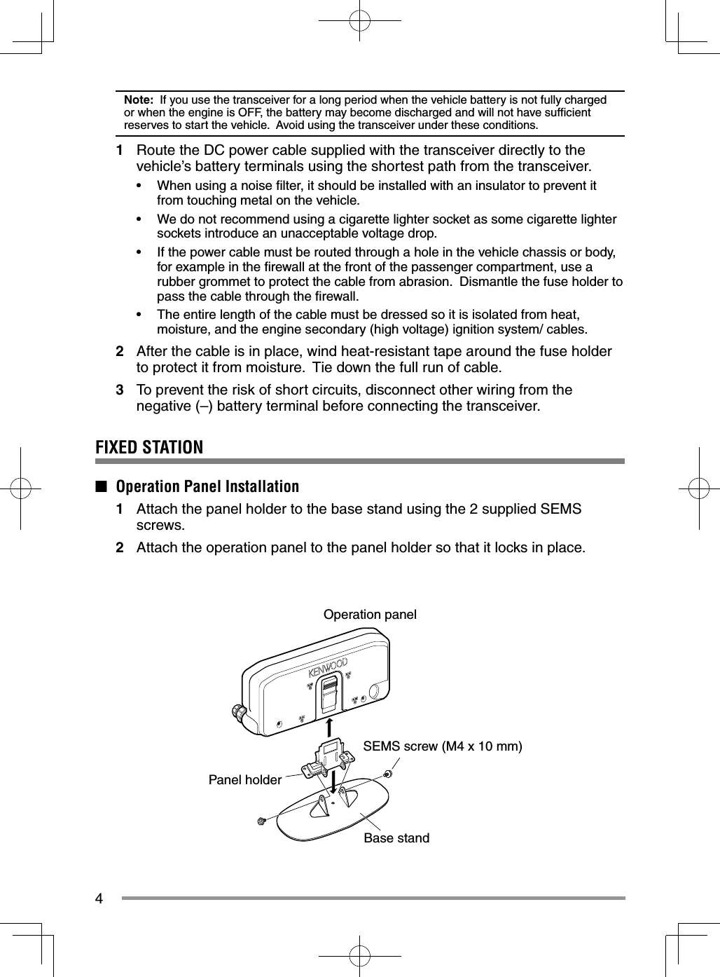
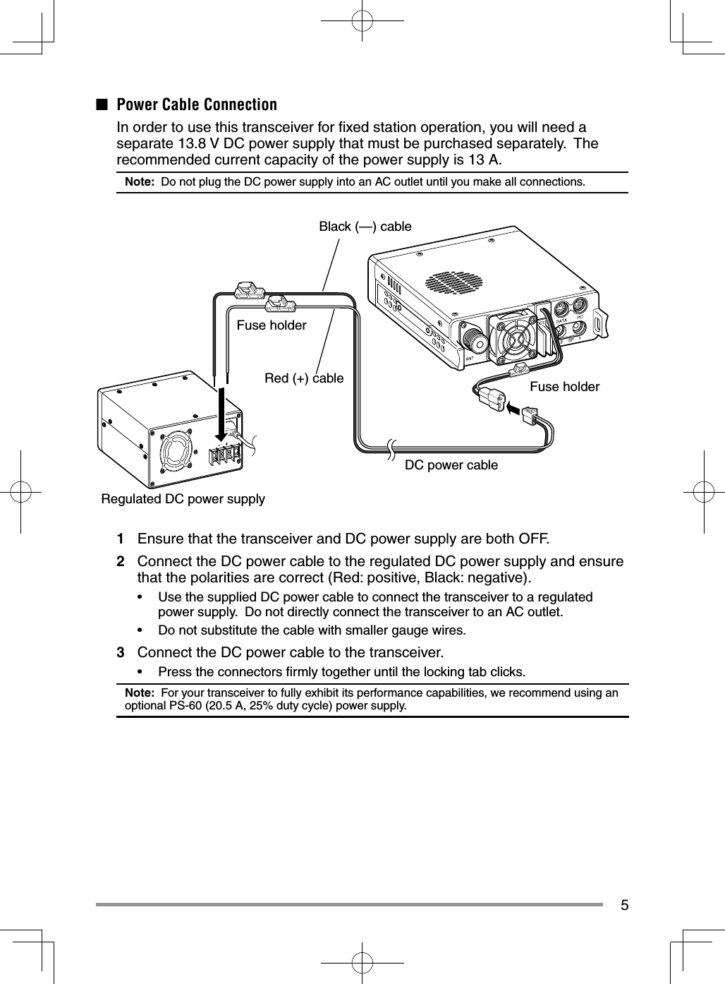
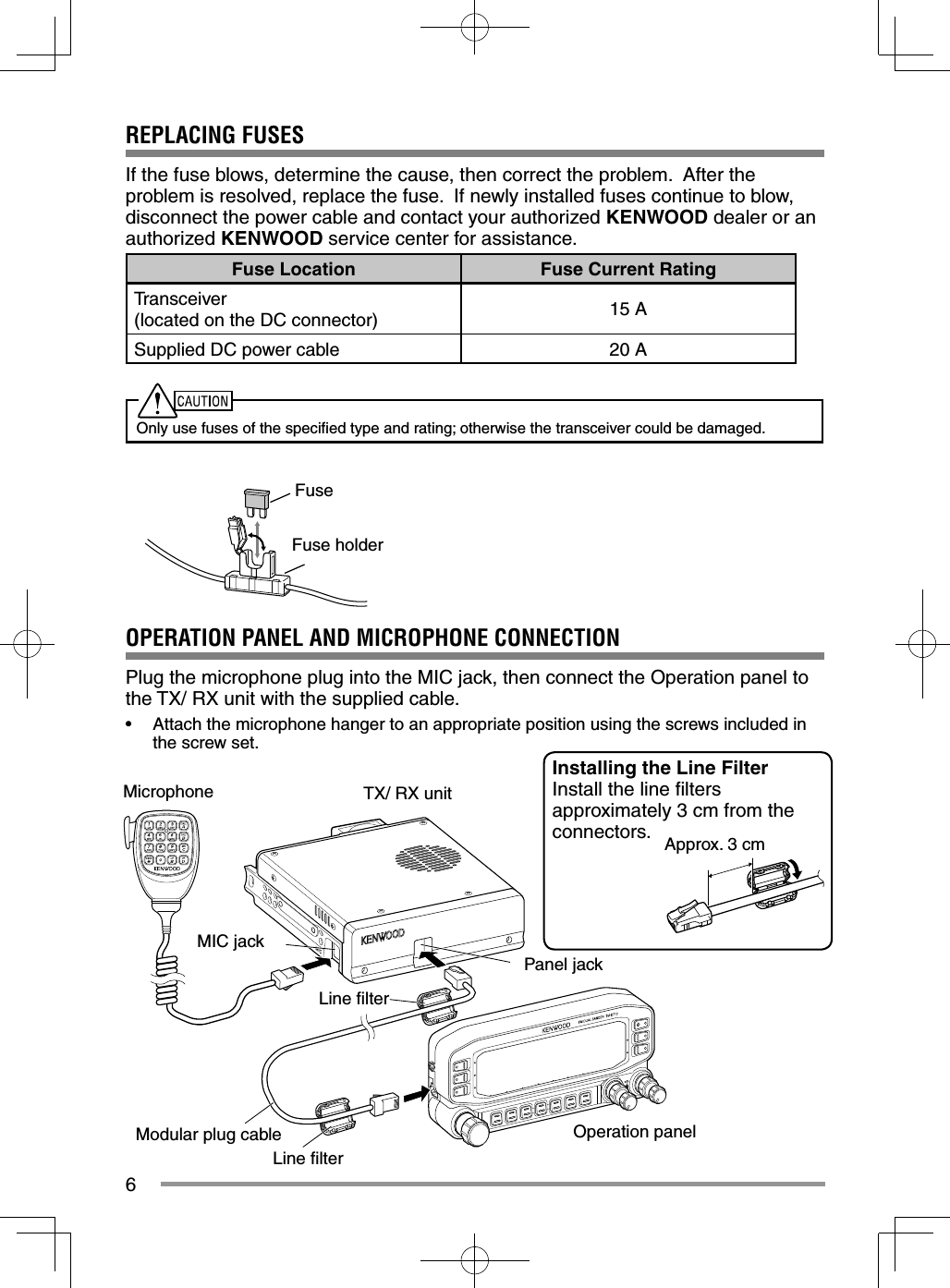
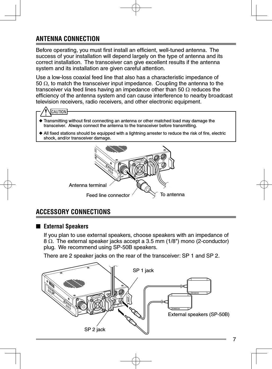
User Instructions Guide

![THANK YOUWe are grateful you decided to purchase this KENWOOD FM transceiver. KENWOOD always provides Amateur Radio products which surprise and excite serious hobbyists. This transceiver is no exception. KENWOOD believes that this product will satisfy your requirements for both voice and data communications.FEATURESThis transceiver has the following main features:• A built-in GPS receiver unit.• A built-in 5000 point GPS Logger.• Has a built-in TNC which conforms to the AX.25 protocol. With a portable computer, allows you to enjoy Packet operation quite easily.• Includes a program for dealing with data formats supported by Automatic Packet/ Position Reporting System (APRS®).• Enhanced Programmable Memory (PM) channels store virtually entire current operating environments for your quick recall.• Contains a total of 1000 Memory channels to program frequencies and other various data. Allows each Memory channel to be named using up to 8 alphanumeric characters.• Continuous Tone Coded Squelch System (CTCSS) or Digital Code Squelch (DCS) rejects unwanted calls from other stations.WRITING CONVENTIONS FOLLOWED IN THIS MANUALThe writing conventions described below have been followed to simplify instructions and avoid unnecessary repetition.Instruction ActionPress [KEY]. Momentarily press KEY.Press [KEY] (1s). Press and hold KEY for 1 second or longer.Press [KEY1], [KEY2]. Press KEY1 momentarily, release KEY1, then press KEY2.Press [F], [KEY]. Press the F key to enter Function mode, then press KEY to access its secondary function.Press [KEY] + Power ON. With the transceiver power OFF, press and hold KEY while turning the transceiver power ON.Information on Disposal of Old Electrical and Electronic Equipment and Batteries (applicable for countries that have adopted separate waste collection systems)Products and batteries with the symbol (crossed-out wheeled bin) cannot be disposed as household waste. Old electrical and electronic equipment and batteries should be recycled at a facility capable of handling these items and their waste byproducts. Contact your local authority for details in locating a recycle facility nearest to you. Proper recycling and waste disposal will help conserve resources whilst preventing detrimental effects on our health and the environment.](https://usermanual.wiki/JVC-KENWOOD/397700.User-Instructions-Guide/User-Guide-2083324-Page-4.png)
![8GETTING ACQUAINTEDOPERATION PANEL (FRONT)■ In Normal Modea CALLPress [CALL] to select the Call channel. Press [CALL] (1s) to start Call scan. b VFOPress [VFO] to enter VFO mode, then rotate the Tuning control to select an operating frequency. Press [VFO] (1s) to start VFO scan. c MRPress [MR] to enter Memory Channel mode, then rotate the Tuning control to select a Memory channel. Press [MR] (1s) to start Memory scan.d Tuning ControlRotate to select an operating frequency or Memory channel, change the scan direction, etc. Press the Tuning control to enter MHz mode (while in VFO or Call mode) or to toggle the display between the channel name and frequency (while in Memory Channel mode). Press Tuning control (1s) to start MHz scan or Group scan.e KEY Each time you press [KEY], the functions toggle as follows: APRS key function ON >> GPS key function ON >> Normalf FPress [F] to enter Function mode. Press [F] (1s) to turn the transceiver key lock function ON and OFF.](https://usermanual.wiki/JVC-KENWOOD/397700.User-Instructions-Guide/User-Guide-2083324-Page-16.png)
![9g TONEPress [TONE] to turn the Tone function ON. Each time you press [TONE], the functions toggle as follows: Tone ON >> CTCSS ON >> DCS ON >> Cross Tone ON >> OFF.h REVPress [REV] to turn the Reverse function ON or OFF. Press [REV] (1s) to turn the Automatic Simplex Checker ON.i LOWPress [LOW] to toggle the transmit output power as follows: High Power –> Middle Power –> Low Power.j PF1Press [PF1] to activate its programmable function. The default function is “Weather Channel” (TM-D710GA)/“Frequency Band Select” (TM-D710GE).k PF2Press [PF2] to activate its programmable function. The default function is “Operation Band Select”.l BAND SEL (VOL) ControlRotate the [BAND SEL] control to adjust the speaker volume. Press the left [BAND SEL] to select the A band. Press the right [BAND SEL] to select the B band. Press [BAND SEL] (1s) to toggle between single and dual-band mode.m SQL ControlRotate the [SQL] control to adjust the squelch level. Clockwise opens the squelch and counterclockwise tightens the squelch.n TNCPress [TNC] to turn the built-in TNC ON and the APRS (or NAVITRA) mode ON. Each time you press [TNC], the mode toggles as follows: APRS (or NAVITRA) mode ON >> PACKET mode ON >> TNC OFF.• When the built-in TNC turns on, “OPENING TNC” appears on the display.• When “OPENING TNC” appears on the display, the mode cannot be changed.o PMPress [PM] to enter the PM (Programmable Memory) channel selection mode. p Press [ ] to turn the transceiver power ON and OFF.](https://usermanual.wiki/JVC-KENWOOD/397700.User-Instructions-Guide/User-Guide-2083324-Page-17.png)
![10■ In Function Modea C.INPress [C.IN] to store the current operating frequency to the Call channel.b M>VPress [M>V] to copy the current Memory channel or Call channel to the VFO (memory shift).c M.INSelect a Memory channel, then press [M.IN] to store the current operating frequency in the Memory channel.d Tuning Control Press the Tuning control to enter Menu mode. e F OFFPress [F OFF] to return Normal mode. f T.SEL While Tone, CTCSS, or DCS is ON, press [T.SEL] to enter CTCSS or DCS setup mode. g SHIFT Press [SHIFT] to enter Offset Direction selection mode. Each time you press [SHIFT], the offset direction toggles as follows:plus (+) direction –> minus (–) direction –> –7.6 MHz (TM-D710GE only) –> OFF.h MUTE Press [MUTE] to turn the Mute function ON or OFF.i VISUALPress [VISUAL] to turn the Visual Scan function ON and OFF.j BAND SEL (VOL) ControlRotate the [BAND SEL] control to adjust the speaker volume. Press [BAND SEL] to select a frequency band.](https://usermanual.wiki/JVC-KENWOOD/397700.User-Instructions-Guide/User-Guide-2083324-Page-18.png)
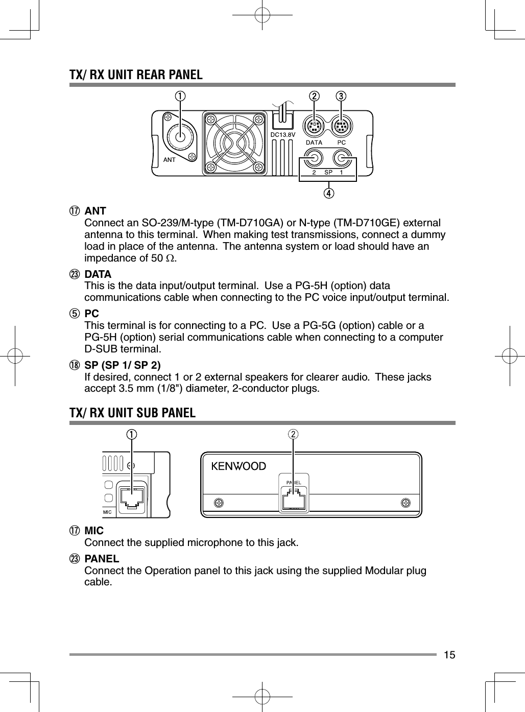
![11k SQL ControlRotate the [SQL] control to adjust the squelch level. Clockwise opens the squelch and counterclockwise tightens the squelch.l DXPress [DX] to turn the DX PacketClusters Monitor ON and OFF.m P.INPress [P.IN] to enter PM Channel registration mode.n Press [ ] to turn the transceiver power ON and OFF.OPERATION PANEL (REAR & LEFTa GPSConnect the external GPSreceiver or the Weather Station to this jack using the supplied cable with a 2.5 mm (1/10") 3-conductor plug.b COMThis terminal is for connecting to a PC. Use a PG-5G (option) cable when connecting the built-in TNC to a computer D-SUB terminal.c Panel jackConnect the TX/ RX unit to this jack using the supplied Modular plug cable.](https://usermanual.wiki/JVC-KENWOOD/397700.User-Instructions-Guide/User-Guide-2083324-Page-19.png)
![16MICROPHONE (MC-59)Keypad serial dataNo ConnectionMIC, 600 impedanceGND (MIC)PTTGNDDC 8 V, 100 mA maxNo ConnectionMicrophone Jackq PTT switchPress and hold, then speak into the microphone to transmit.w DTMF keypadPress these keys to make DTMF calls, enter frequencies, or enter characters.e CALL/ AFunctions the same as the transceiver front panel [CALL] key. This is also the PF4 key and can be reprogrammed with a programmable function.r VFO/ BFunctions the same as the transceiver front panel [VFO] key. This is also the PF3 key and can be reprogrammed with a programmable function.t MR/ CFunctions the same as the transceiver front panel [MR] key. This is also the PF2 key and can be reprogrammed with a programmable function.y PF/ DPress to toggle between bands A and B. This is also the PF1 key and can be reprogrammed with a programmable function.u UP/ DWNFunctions the same as the transceiver Tuning control.](https://usermanual.wiki/JVC-KENWOOD/397700.User-Instructions-Guide/User-Guide-2083324-Page-24.png)
![17BASIC OPERATIONSSWITCHING THE POWER ON/ OFFPress the [ ] switch to switch the transceiver ON.• The power on message momentarily appears on the display.• If the transceiver power on password has been activated {Menu No.998}, you must fi rst enter your password before you can operate the transceiver.Press the [ ] switch again to switch the transceiver OFF.ADJUSTING THE VOLUMERotate the [BAND SEL] (VOL) control of your selected band clockwise to increase the volume and counterclockwise to decrease the volume.Note: Some functions of this transceiver, such as the beep and voice announcements, have their own volume settings. Adjust those settings to your desired values.](https://usermanual.wiki/JVC-KENWOOD/397700.User-Instructions-Guide/User-Guide-2083324-Page-25.png)
![18ADJUSTING THE SQUELCHSquelch is used to mute the speaker when no signals are present. With the squelch level set correctly, you will hear sound only while actually receiving a signal. The higher the squelch level selected, the stronger the signals must be in order to hear them.Rotate the [SQL] control of your selected band, when no signals are present, and select the squelch level at which the background noise is just eliminated.SELECTING A BANDPress the left [BAND SEL] control to select band A and the right [BAND SEL] control to select band B.• The icon appears at the top of the band on which you are operating and the icon appears at the top of the band on which you are currently set to transmit. Band A (left [BAND SEL] control): Band B (right [BAND SEL] control):](https://usermanual.wiki/JVC-KENWOOD/397700.User-Instructions-Guide/User-Guide-2083324-Page-26.png)
![19Pressing [PF2] allows you to switch the operating band between bands A and B, while maintaining the original band as the transmit band. Band A is the transmit band and band B is the operating band: Band A is both the transmit and operating band:](https://usermanual.wiki/JVC-KENWOOD/397700.User-Instructions-Guide/User-Guide-2083324-Page-27.png)
![20SELECTING DUAL BAND MODE/ SINGLE BAND MODE You can switch the transceiver between dual band operation and single band operation by pressing [BAND SEL] (1s) of your selected band. Dual band mode: Single band mode (band A only):Note: You can also turn the center partition bar display off {Menu No. 928}.SELECTING A FREQUENCY BANDYou can change the default frequency band for bands A and B.1 Select band A or B by pressing the [BAND SEL] control or [PF2].2 Press [F], [BAND SEL] of your selected band.• Each time you press [F], [BAND SEL], you cycle to the next frequency band.• The default setting of the [PF1] key also allows you to cycle to the next frequency band (TM-D710GE).• When masking a band, you are restricted to using only the selectable band.• When receiving 2 signals on the same band, the image interference, sensitivity, etc., performance will decrease.• Band A: 118 >> 144 (default) >> 220 >> 300 >> 430/440 (MHz).• Band B: 144 >> 220 >> 300 >> 430/440 (default) >> 1200 (MHz).Note: TM-D710GE models use the 430 MHz band and TM-D710GA models use the 440 MHz band.](https://usermanual.wiki/JVC-KENWOOD/397700.User-Instructions-Guide/User-Guide-2083324-Page-28.png)
![21Frequency ranges:• 118 MHz: 118 ~ 135.995 MHz • 144 MHz: 136 ~ 199.995 MHz• 220 MHz: 200 ~ 299.995 MHz • 300 MHz: 300 ~ 399.995 MHz• 430/440 MHz: 400 ~ 523.995 MHz • 1200 MHz: 800 ~ 1299.990 MHz (TM-D710GA: excluding cellular band)SELECTING AN OPERATING MODEThere are 3 operating modes available to choose from: VFO mode, Memory Channel mode, and Call Channel mode.■ VFO Mode VFO mode allows you to manually change the operating frequency.1 Press [VFO] to enter VFO mode.2 Rotate the Tuning control to select your desired operating frequency.• You can also adjust the frequency by using the microphone [UP]/[DWN] keys.• The default step frequency for the Tuning control varies according to the type and operating band:Type 144 MHz 430/440 MHzTM-D710GA 5 kHz 25 kHzTM-D710GE 12.5 kHz 25 kHz• To adjust the frequency by a larger amount, you can press the Tuning control to enter MHz mode. While in MHz mode, rotate the Tuning control to adjust the frequency in steps of 1 MHz. Press the Tuning control again to exit MHz mode and adjust the frequency using the normal step frequency.](https://usermanual.wiki/JVC-KENWOOD/397700.User-Instructions-Guide/User-Guide-2083324-Page-29.png)
![22■ Memory Channel Mode Memory Channel mode allows you to quickly select a frequently used frequency and related data which you have saved in the transceiver memory.1 Press [MR] to enter Memory Channel mode.2 Rotate the Tuning control to select your desired Memory channel.■ Call Channel Mode Call Channel mode allows you to quickly select a preset channel to allow immediate calls on that frequency. The Call channel can be conveniently used as an emergency channel within your group.1 Select your desired band (A or B).• The Call channel has a dedicated frequency for both bands A and B. The default frequency for band A is 144 MHz. The default frequency for band B is 430/440 MHz. 2 Press [CALL] to enter Call Channel mode.• The icon appears on the display.3 Press [CALL] again to return to your previous operating frequency.](https://usermanual.wiki/JVC-KENWOOD/397700.User-Instructions-Guide/User-Guide-2083324-Page-30.png)
![23TRANSMITTING1 Select your desired band and frequency/channel.2 Press and hold the microphone [PTT] switch and speak into the microphone to transmit.• The icon and the RF power meter appear on the display for the selected transmit band. The RF power meter shows the relative transmit output power.• The / / icon(s) appear on the display, depending on what output power you have selected.• Speak into the microphone in your normal voice, while keeping the microphone approximately 5 cm from your mouth. Speaking too close to the microphone or too loudly may increase distortion and reduce intelligibility of your signal at the receiving station.3 When you fi nish speaking, release the [PTT] switch.Note: When the transceiver overheats because of ambient high temperature or continuous transmission, the protective circuit may function to lower transmit output power.](https://usermanual.wiki/JVC-KENWOOD/397700.User-Instructions-Guide/User-Guide-2083324-Page-31.png)
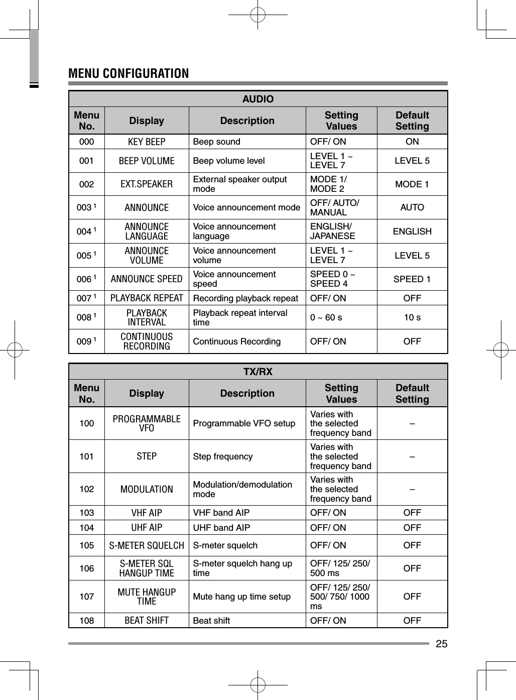
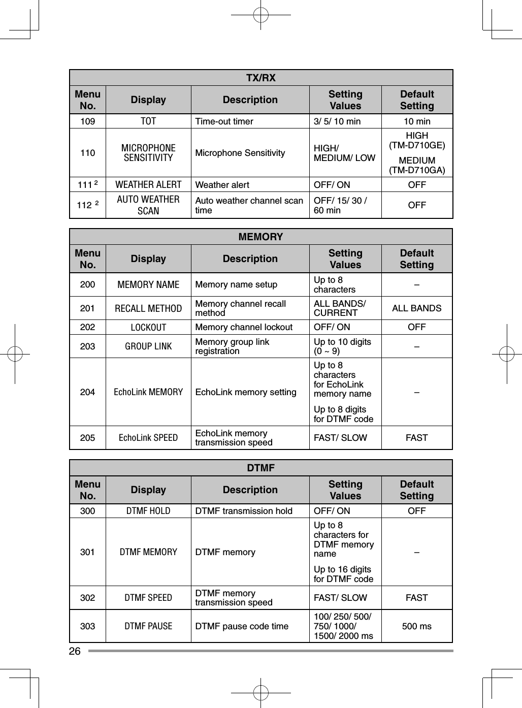
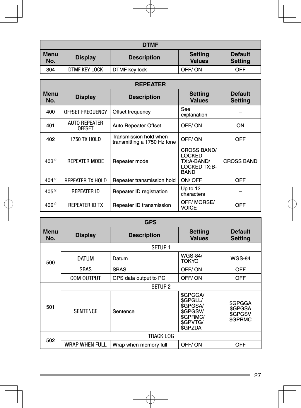
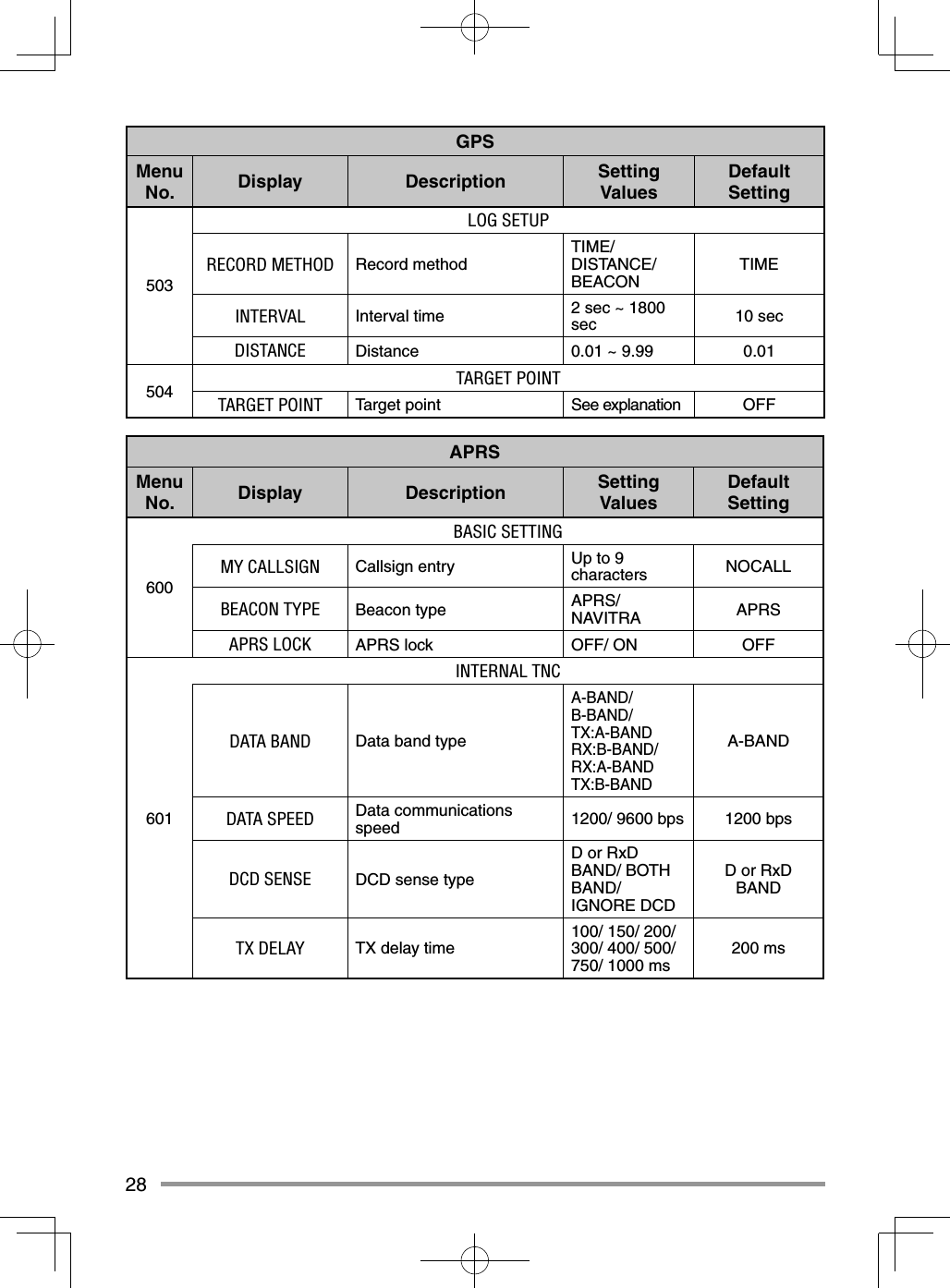
![24MENU MODEMany functions on this transceiver are selected or confi gured through the Menu instead of physical controls. Once you become familiar with the Menu system, you will appreciate the versatility it offers.MENU ACCESS1 Press [F], Tuning control to access the Menu.• The setup category name appears on the display.2 Rotate the Tuning control to select your desired setup category.3 Press the Tuning control to set the selected category.• The Menu name and number appear on the display.4 Rotate the Tuning control to select your desired Menu.5 Press the Tuning control to set the selected Menu.6 Rotate the Tuning control to select your desired value for the selected Menu.7 Press the Tuning control to set the selected value.8 Repeat steps 2 to 7 to set up additional Menus.• Press [ESC] at any time to exit Menu mode.• Press [BACK] at any time to cancel the Menu setup and return to the Menu selection.](https://usermanual.wiki/JVC-KENWOOD/397700.User-Instructions-Guide/User-Guide-2083324-Page-32.png)
![36CHARACTER ENTRYCertain menus require you to enter characters, such as the power on message and memory names. When character entry is required, a cursor will appear on the display.1 Press the Tuning control.• The cursor will blink.2 Rotate the Tuning control to select your desired character.3 Press the Tuning control to set the selected character.• The cursor will move to the next digit.• You can move the cursor to the left or right by pressing [] or [].• You can insert one space by pressing [SPACE].• You can insert a character by pressing [INS].• You can delete the selected character by pressing [CLR]. 4 Repeat steps 2 and 3 to enter the remaining characters.• Press [ESC] at any time to exit Menu mode.• Press [BACK] at any time to cancel the Menu setup and return to the Menu selection.](https://usermanual.wiki/JVC-KENWOOD/397700.User-Instructions-Guide/User-Guide-2083324-Page-44.png)
![37■ Microphone Keypad Character Entry The microphone keys can also be used to enter characters. Refer to the table below for characters corresponding to microphone keys.Key Character Display (with each press of the key) Key Character Display (with each press of the key)1QZ1 7PRS72ABC28TUV83DEF3 9WX Y 94GH I 4 0(space) 05JKL5 Not used6MNO6 #–/@For a memory name, status text, and message:Key Character Display (with each press of the key)1qz1QZ2abc2ABC3def3DEF4gh i 4GHI5jkl5JKL6mno 6MNO7p r s 7PRS8tuv8TUV9wxy9WXY0(space) 0Not used#?! ’ .,–/&#%()<>;:”@ The microphone [A] ~ [D] keys have special functions assigned to them: [A]: Functions the same as [CLR] [B]: Functions the same as [] [C]: Functions the same as [] [D]: Functions the same as the Tuning control](https://usermanual.wiki/JVC-KENWOOD/397700.User-Instructions-Guide/User-Guide-2083324-Page-45.png)
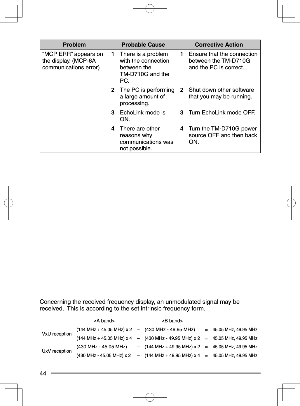
![43TROUBLESHOOTINGThe problems described in this table are commonly encountered operational malfunctions and are usually not caused by circuit failure.Problem Probable Cause Corrective ActionThe transceiver will not power up after connecting a 13.8 V DC power supply and pressing [ ]. Nothing appears on the display.1 The power cable was connected backwards.2 One or more of the power cable fuses are open.1 Connect the supplied DC power cable correctly (red to + terminal and black to – terminal).2 Look for the cause of the blown fuse(s). After inspecting and correcting any problems, install a new fuse(s) with the same ratings.The frequency cannot be selected by turning the Tuning control or by pressing microphone [UP]/[DWN].Memory Recall was selected.Press [VFO].Most keys and the Tuning control do not function.1 One of the Lock functions is ON.2 The transceiver is in Channel Display mode.1 Unlock all of the Lock functions.2 With the transceiver power OFF, press [LOW] + Power ON to exit Channel Display mode.Memory channels cannot be selected by turning the Tuning control or by pressing microphone [UP]/[DWN].No data has been stored in any Memory channel.Store data in some Memory channels.You cannot transmit even though you are pressing [PTT].1 The microphone plug was not inserted completely into the transceiver.2 You selected a transmit offset that places the transmit frequency outside the allowable range.3 The external TNC is transmitting.1 Switch the power OFF, then insert the microphone plug until the locking tab clicks in place.2 Turn the offset shift function OFF.3 Press [PTT] after the TNC has fi nished transmitting.](https://usermanual.wiki/JVC-KENWOOD/397700.User-Instructions-Guide/User-Guide-2083324-Page-51.png)