Japan Radio JRN-130K 3G/GSM IT Controller User Manual
Japan Radio Co Ltd. 3G/GSM IT Controller
UserManual.wiki
>
Japan Radio
>
JRN 130K User Manual
User manual
Navigation menu
Upload a User Manual
Namespaces
Wiki Guide
HTML
PDF
Info
Views
User Manual
Discussion / Help
Navigation
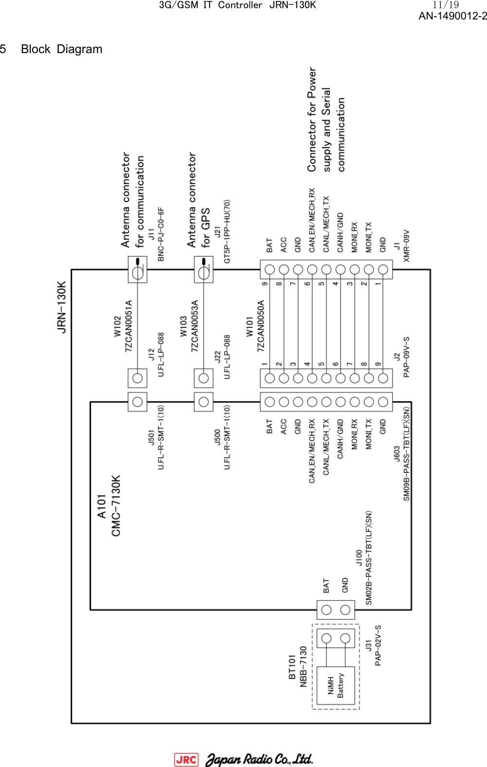
![3G/GSM IT Controller JRN-130K 10/19 AN-1490012-2 4.1 External connector specification 4.1 Software JRN-130K application software external I/F specifications is prescribed about the command list and block structure about software. Implement the software that customers have created. NO. Items Specification performance 1 Power/Serial connector XMR (JST) Model : XMR-09V [Cable side connector model : XMP-09V(JST)] 2 GPS antenna connector GT5 (HIROSE) Model : GT5P-1PP-HU(70) 3 Communication antenna BNC (Yuetsu Seiki) Model : BNC-PJ-C0-6F](https://usermanual.wiki/Japan-Radio/JRN-130K/User-Guide-2424127-Page-10.png)