Japan Radio JRN-130K 3G/GSM IT Controller User Manual
Japan Radio Co Ltd. 3G/GSM IT Controller
User manual

JRN-130K
3G/GSM IT Controller
User Manual
Doc# : AN-1490012-2 Ver.1.02
Date: Oct 15, 2014
@Copyright
Japan Radio Co., Ltd.
Mobile Communication Group
Engineering Department
Communication Products Division

3G/GSM IT Controller JRN-130K 2/19
AN-1490012-2
History
Date Number The contents of change
Sep 16, 2014 1.00 DRAFT
Oct 16, 2014 1.01
Oct 16, 2014 1.02

3G/GSM IT Controller JRN-130K 3/19
AN-1490012-2
Index
1 Introduction.............................................................................................................................. 4
2 Composition ............................................................................................................................ 5
3 Function .................................................................................................................................. 6
4 Product specification .............................................................................................................. 7
5 Block Diagram ...................................................................................................................... 11
6 External Interface ................................................................................................................. 12
7 Outline ................................................................................................................................... 14
8 Option .................................................................................................................................... 15
9 Compliance with FCC and IC Rules and Regulations ...................................................... 18
3G/GSM IT Controller JRN-130K 4/19
AN-1490012-2
1 Introduction
3G/GSM IT Controller (JRN-130K) is a vehicle small terminal to have the GPS measureme
nt function and the 3G/GSM communication function, and to use it for management and posit
ional information track / theft pursuit etc. of the vehicle.
As a communications protocol TCP/IP are mounted.
The terminal made by the Gemalto’s PHS8-P is installed.
1.1 Overview
The main specification is presented as follows.
No. Items Specification Remarks
1 Comnication
module
3G/GSM Communication modu
le
(PHS8-P Gemalto)
UMTS 800/850 BandⅥ
UMTS 800/850 BandⅤ*
UMTS 900 BandⅧ*
UMTS 1900 BandⅡ*
UMTS 2100 BandⅠ
GSM850
GSM900
GSM1800
GSM1900
*:Only compatible module
2 Data transfer
GPRS: Multislot Class 12
EGPRS: Multislot Class 12
CSD: V.110, RLP, non-transpa
rent
3 Communication
Antenna
DP-BR0-DSC(BNC)
NIPPON ANTENNA
4 GPS
Antenna NAY-3930G
5 Internal Battery NBB-1300(1300mAh/6.0V)
6 Current and Voltage DC+20V~+32V 400mA max
Power-saving : 7.5mAmax
3G/GSM IT Controller JRN-130K 5/19
AN-1490012-2
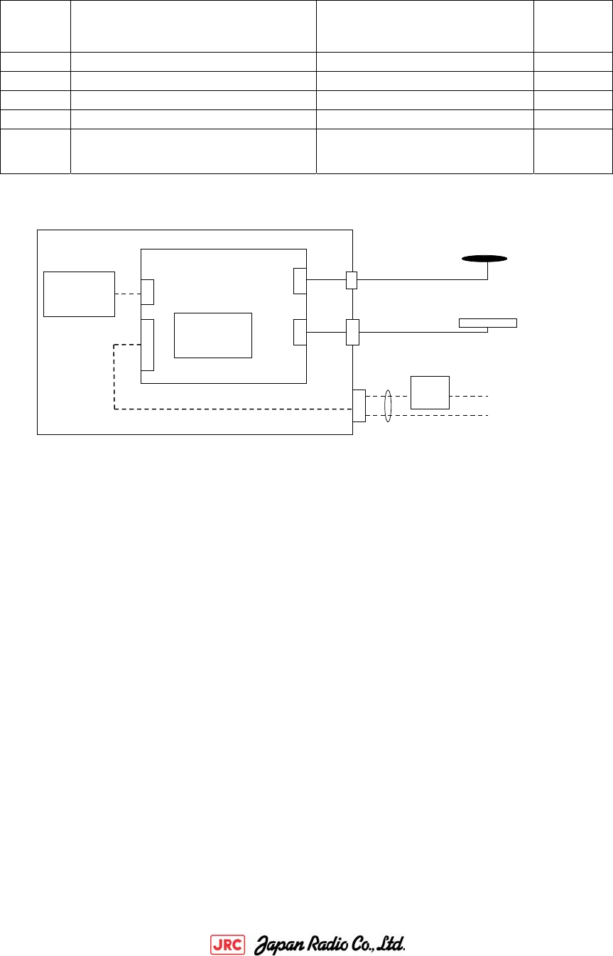
2 Composition
NO.
Equipment
Model
Quantity
1 3G/GSM Controller JRN-130K 1
(1) Communication Module PHS8-P Gemalto 1
(2) Battery pack NBB-1300 1
2 GPS Antenna NAY-3930G 1
3 3G/GSM Communication antenna DP-BR0-DSC(BNC)
NIPPON ANTENNA
1
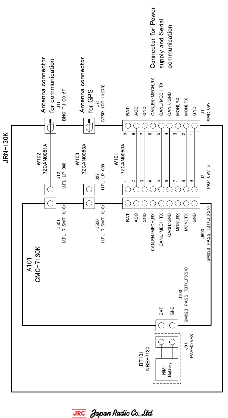
Power Supply & Control Block
Communication
Module
IT Controller
Fuse
3G/GSM Communication
Antenna
GPS Antenna
Connection I/F Cable
)
To Battery
To Construction machine
Battery pack
(Note#1)
Please prepare IF cable by the visitor side.
(Note#2)
A connection I/F cable requires a fuse because of over-current protection.
Please insert the fuse in three places of a battery, GND, and ACC.
(Note#3)
Please do not take a power supply from DC cigar.
It becomes the cause that operation is poor, according to loose connection.

3G/GSM IT Controller JRN-130K 6/19
AN-1490012-2
3 Function
(1) Operation in ACC OFF executes the following.
-1. Send data in daytime and nighttime.
-2. Respond to calling from the server.
-3. Acquisition of information on the actual location by GPS,
and Generation of warning outside area.
(2) Storage of operation data
(3) Timer
Even if the main source of power is cut, the date and time are maintained.
(4) Backup
The re-charge battery is installed.
Even if it disconnects a power supply, the operational mode and network transmission setting
of IT controller are held.
(5) Serial communication ports
Connection I/F (CAN), 115200bps(monitor)
(6) GPS function
Present location is acquired.(WGS84)
(7) 3G/GSM communication
(8) Software rewriting function
A software rewriting is done by using the monitor port.
(9) Serial communications with the external equipment are done by the serial commands.
1) Key ON
2) Engine ON
3) Key OFF
4) Alarm
5) Fuel residual quantity
6) Engine amount of water
7) Engine oil level
8) Hydraulic oil level
9) Engine oil pressure
10) Engine water temperature
11) Air cleaner
12) Charge
13) DS (compulsive key OFF)
14) RT (the present state inquiry)
15) HS (foxtail millet meter change)
16) CO (command)
17) Automatic key-off judging processing
(10) Communication protocol
It transmits to the mail server by the e-mail.
(11) Time Zone
Setting UTC+α, and operating.
3G/GSM IT Controller JRN-130K 7/19
AN-1490012-2
4 Product specification
4.1 Common Specification
NO. Items
Specification performance
1 Power supply
voltage
DC+20 to +32V
2 Battery pack NiMH rechargeable battery NBB-1300(1300mAh/6.0V)
3 SIM
Interface
1.8V/3.0V
4 Current Communication: max current Less than 400mA(+25℃)
Idle:7.5mAmax(When not charging the battery)
5 Circumference
environment
Operation: -30 to +70 degree C
Preservation: -40 to +80 degree C
Humidity of operation: 0% to 90% (don't dew)
At use in battery,
Operation: -20 to +70 degree C
0 to 70 degree C of the charge operates.
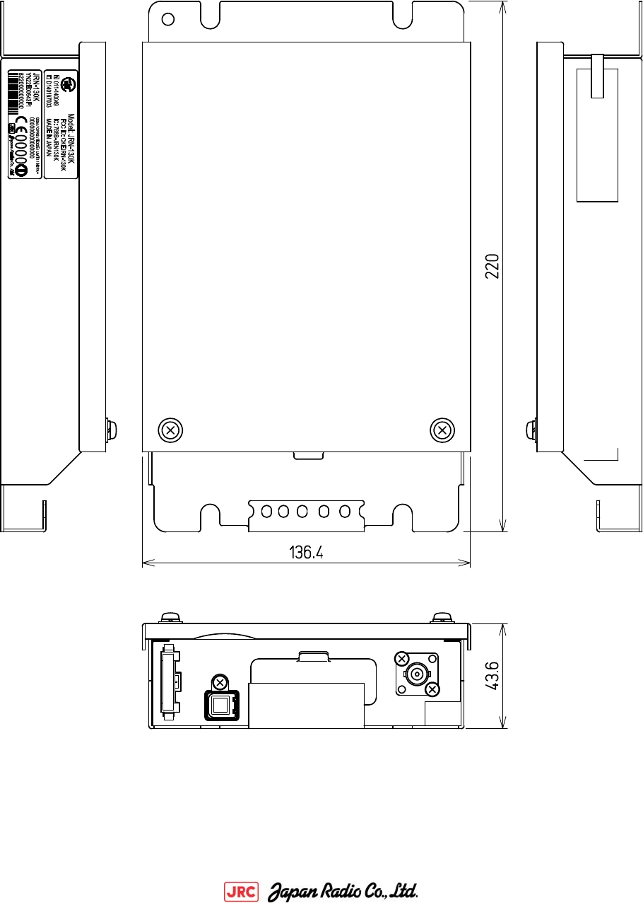
6 Dimension 136.4(W)×220.0(D)×43.6(H) mm
7 Weight 1,300g or less
8 Case material SPCC
3G/GSM IT Controller JRN-130K 8/19
AN-1490012-2
4.1 Serial Interface Specification
(1) A. DTE CAN
NO. Items Specification performance
1 Data transmission S
A
E J1939
2 Speed 250/500 kbps
3 Communication format Extension 29bit
4 Switch to the RS-232C B
y
the chi
p
j
um
p
e
r
chan
g
e
(1) B. DTE RS-232C
NO. Items Specification performance
1 Data transmission Half duplex start-stop synchronization
2 Signal level RS-232C
3 Speed 4800bps
4 Frame length Variable-length
5 Data Length 8 bit
6 Start bit 1 bit
7 Parity bit None
8 Stop bit 1 bit
(2) Console(Debug)
NO. Items Specification performance
1 Data transmission Half duplex start-stop synchronization
2 Signal level RS-232C
3 Speed 115200bps
4 Frame length Variable-length
5 Data Length 8 bit
6 Start bit 1 bit
7 Parity bit None
8 Stop bit 1 bit
9 Character EUC

3G/GSM IT Controller JRN-130K 9/19
AN-1490012-2
4.1 GPS Receiver Specification
NO. Items Specification performance
1 Model CCA-705JZ (JRC)
2 Receiving system Max 16hannel (high-speed search channel)
3 Received frequency 1575.42MHz(L1)、C/A code
4 Land survey system WGS-84(Default)
5 Time system UTC
6 Positioning accuracy
Position
5.3m 2DRMS
Speed 0.04m/sec. RMS
Direction Less than 0.14°RMS (Speed 60km/h)
7 Speed 1 sec
8 T.T.F.F
(Without signal
discontinuation)
Open skies
Hot start: 4s typ./15s max.
Warm start: 33s typ./55s max.
Cold start: 35s typ./60s max.
4.1 3G/GSM module Specification
By PHS8-P 3G/GSM communication module specification.

3G/GSM IT Controller JRN-130K 10/19
AN-1490012-2
4.1 External connector specification
4.1 Software
JRN-130K application software external I/F specifications is prescribed about the command list a
nd block structure about software.
Implement the software that customers have created.
NO. Items Specification performance
1 Power/Serial connector XMR (JST)
Model : XMR-09V
[Cable side connector model : XMP-09V(JST)]
2 GPS antenna connector GT5 (HIROSE)
Model : GT5P-1PP-HU(70)
3 Communication antenna BNC (Yuetsu Seiki)
Model : BNC-PJ-C0-6F
3G/GSM IT Controller JRN-130K 11/19
AN-1490012-2
5 Block Diagram
3G/GSM IT Controller JRN-130K 12/19
AN-1490012-2
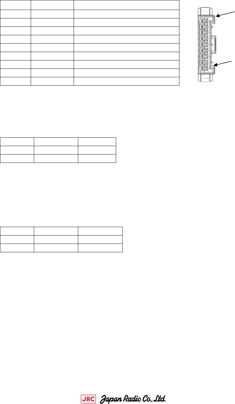
6 External Interface
6.1 External Interface Specification
Pin Assign
NO Name Remarks
1 GND GND
2 Moni-Tx Monitor→ITcontroller
3 Moni-Rx ITcontroller→Monitor
4 CAN H CAN Low-Level Voltage I/O
5 CAN L CAN High-Level Voltage I/O
6 CAN_EN CAN Enable
7 GND GND
8 ACC ACC signal
9 BAT Main battery
6.2 GPS Antenna Connector
Pin Assign
6.1 Communication Antenna Connector
Pin Assign
NO. Name Remarks
1 RF Receive
2 GND GND
NO. Name Remarks
1 RF TX/RX
2 GND GND
1
9
3G/GSM IT Controller JRN-130K 13/19
AN-1490012-2
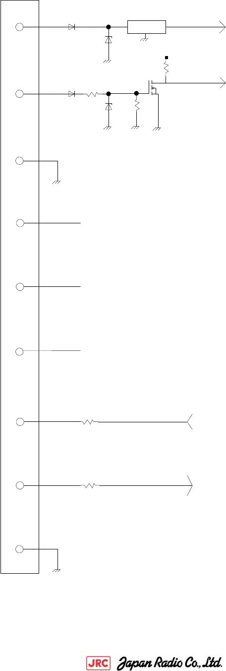
6.1 Equivalent circuit
BAT
GND
ACC
CANH
CANL
GND
MON-R
MON-T
DC/DC Converte
r
to PWR SPL
Y
+3.3V
To CPU
330
330 from Serial Interface IC
from Serial Interface
9
8
7
4
5
6
3
2
1
CAN_EN En
ab
l
e
co
n
t
r
o
l
c
ir
cu
i
t
from CAN Interface IC
from CAN Interface IC
3G/GSM IT Controller JRN-130K 14/19
AN-1490012-2
7 Outline
3G/GSM IT Controller JRN-130K 15/19
AN-1490012-2
8 Option
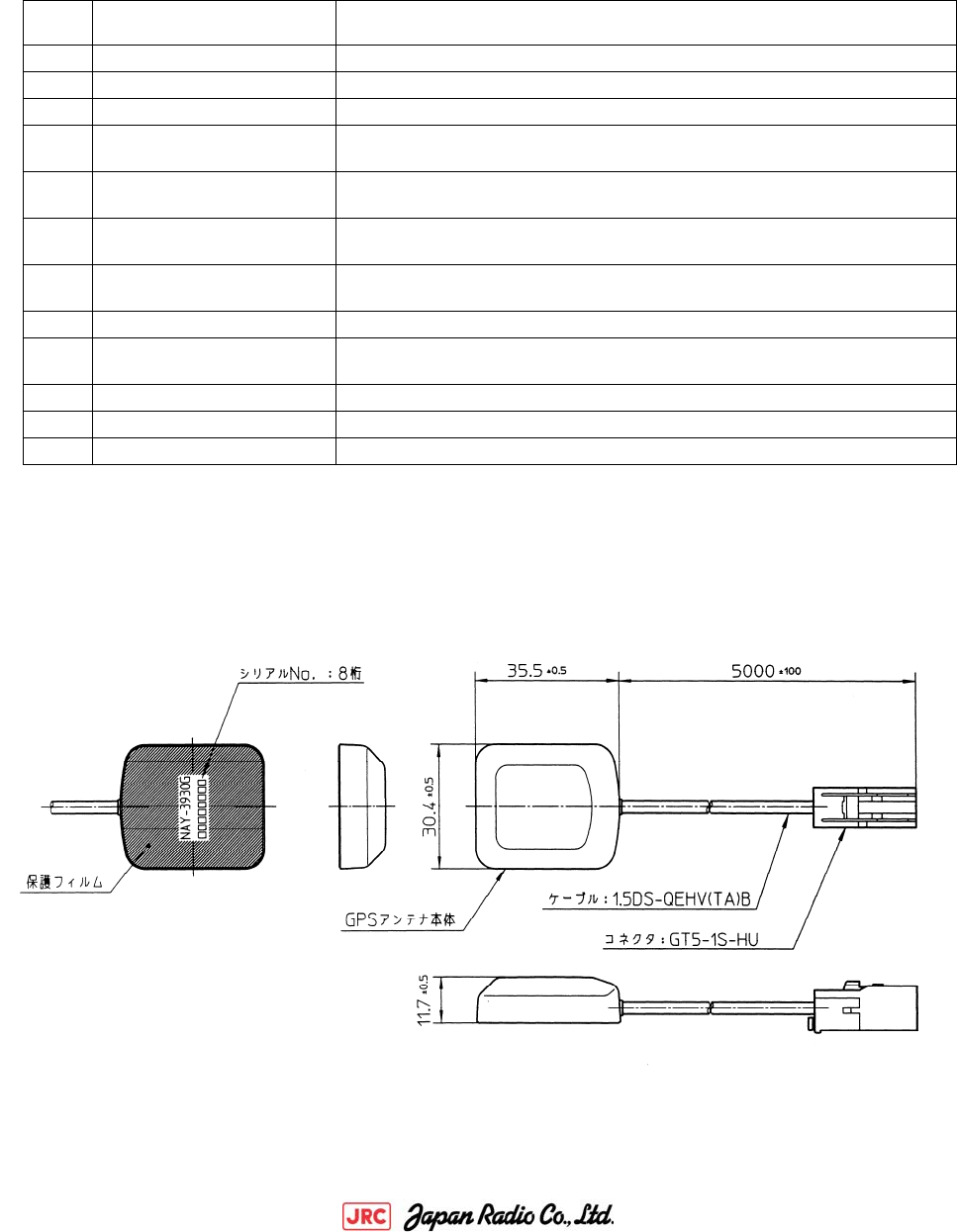
8.1 GPS antenna
(1) Specification
NO. Items Specification performance
1 Power supply voltage 2.7V to 3.3V
2 Consumption current 12mA to 30mA
3 Cable 1. 5D Cable and 5M (Black)
4 Temperature range of
operation
-30 degree C to +85 degree C
5 Storage temperature
range
-40 degree C to +100 degree C
6 Humidity 20% to 95%
(relativity, however thing without dew condensation)
7 Received frequency
range
1575. 42±1.023MHz
8 Polarized wave Right-handed circular polarization
9 Profit 25±6dBi
(ascending vertical angle = 90 degrees)
10 Output impedance 50 ohms
11 OUTPUT VSWR 2.0, or less
12 Connector GT5-1P-HU (HIROSE)
(2) Outline
単位:mm

3G/GSM IT Controller JRN-130K 16/19
AN-1490012-2
8.2 Communication antenna
(1)Specification
No. Items Specification performance
1 Model DP-BR0-DSC(BNC)
2 Antenna type λ/2 Shortened type Dipole antenna
3 Purpose For the indoor antenna, double-sided tape attachment
4 Weight approximately 70g
5 Environmental
Regulation
RoHS and ELV
6 Frequency 815MHz~2170MHz
A:US800/GSM850 824~849MHz/869~894MHz
B:GSM900 880~915MHz/925~960MHz
C:GSM1800 1710~1766MHz/1805~1880MHz
D:PCS/GSM1900 1850~1910MHz/1930~1990MHz
E:CDMA1X 815~925MHz
F:PHS 1884MHz~1920MHz
G:FOMA (1)830~880MHz/(2)1920~2170MHz
H:SBM(W-CDMA) 1960~1980MHz/2150~2170MHz
I:GPS 1575.42MHz
7 Nominal impedance 50Ω
8 VSWR 2.3 at the end of the cable.
It is measured in free space.
9 Peak gain A,B,E,G-(1) not exceeding 1.0dBi at the end of the
cable.
C,D,F,G-(2) not exceeding 3.5dBi at the end of the
cable.
10 Polarization Vertical
11 Directivity Horizontal plane omni-directional
12 Input power Not exceeding 2W
13 Cable loss
(Reference)
1.5D Coaxial cable
900MHz 1.58dB / 2.5m
2000MHz 2.45dB / 2.5m
14 Operating temperatur
e range
-30 ~+80 degree C
15 Storage temperature
range
-40 ~+85 degree C
16 Operating humidity li
mits
0%~95%
17 Connector BNC
3G/GSM IT Controller JRN-130K 17/19
AN-1490012-2
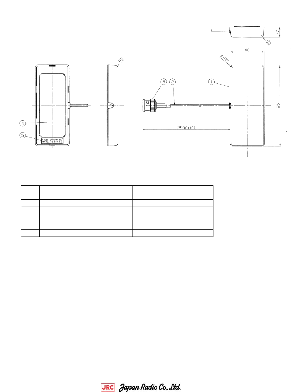
(2)Outline
NO. Items Specification performance
1 Case AES
2 1.5D Coaxial cable 2.5m±10cm
3 BNC C3604・Ep-Cu/Ni
4 Two-sided adhesive tape
5 Label Tetoron film
3G/GSM IT Controller JRN-130K 18/19
AN-1490012-2
9 Compliance with FCC and IC Rules and Regulations
・FCC
This device complies with Part 15 of the FCC Rules. Operation is subject to the following
two conditions: (1) This device may not cause harmful interference, and (2) this device must
accept any interference, including interference that may cause undesired operation.
CAUTION:
Any changes or modifications not expressly approved by the party responsible for compliance
could void the user's authority to operate the equipment.
NOTE: This equipment has been tested and found to comply with the limits for a Class B digital
device, pursuant to part 15 of the FCC Rules. These limits are designed to provide reasonable
protection against harmful interference in a residential installation. This equipment
generates, uses and can radiate radio frequency energy and, if not installed and used in
accordance with the instructions, may cause harmful interference to radio communications.
However, there is no guarantee that interference will not occur in a particular installation.
If this equipment does cause harmful interference to radio or television reception, which
can be determined by turning the equipment off and on, the user is encouraged to try to correct
the interference by one or more of the following measures:
— Reorient or relocate the receiving antenna.
— Increase the separation between the equipment and receiver.
— Connect the equipment into an outlet on a circuit different from that to which the
receiver is connected.
— Consult the dealer or an experienced radio/TV technician for help.
・IC
Operation is subject to the following two conditions: (1) this device may not cause
interference, and (2) this device must accept any interference, including interference that
may cause undesired operation of the device.
This radio transmitter (IC: 768B-JRN130K) has been approved by Industry Canada to operate
with the antenna types listed below with the maximum permissible gain and required antenna
impedance for each antenna type indicated. Antenna types not included in this list, having
a gain greater than the maximum gain indicated for that type, are strictly prohibited for
use with this device.
Antenna type/Model name : Half length dipole antenna/DP-BRO-DCS (BNC)
Maximum Antenna gain : 800MHz-1GHz -0.58dBi
(including the cable loss) 1GHz-2.5GHz +1.05dBi
Nominal impedance : 50Ω
Le présent appareil est conforme aux CNR d'Industrie Canada applicables aux appareils r
adio exempts de licence. L'exploitation est autorisée aux deux conditions suivantes :
B
B

3G/GSM IT Controller JRN-130K 19/19
AN-1490012-2
(1) l'appareil ne doit pas produire de brouillage, et (2) l'utilisateur de l'appareil d
oit accepter tout brouillage radioélectrique subi, même si le brouillage est susceptibl
e d'en compromettre le fonctionnement.
Le présent émetteur radio (IC: 768B-JRN130K) a été approuvé par Industrie Canada pour f
onctionner avec les types d'antenne énumérés ci-dessous et ayant un gain admissible max
imal et l'impédance requise pour chaque type d'antenne. Les types d'antenne non inclus
dans cette liste, ou dont le gain est supérieur au gain maximal indiqué, sont stricteme
nt interdits pour l'exploitation de l'émetteur.
Type d'antenne /Nom du modèle : Antenne dipôle demi-longueur/DP-BRO-DCS (BNC)
Le gain maximal de l'antenne : 800MHz-1GHz -0.58dBi
(La perte du câble est incluse) 1GHz-2.5GHz +1.05dBi
Impédance nominale : 50Ω
・FCC/IC
RF exposure compliance
1) To comply with FCC/IC RF exposure compliance requirements, a separation distance of at
least 20 cm must be maintained between the antenna of this device and all persons.
2) This transmitter must not be co-located or operating in conjunction with any other antenna
or transmitter.
Normes d'exposition RF
1) Afin de se conformer aux normes FCC / IC RF exigences de conformité de l'exposition,
une distance de séparation d'au moins 20 cm doit être maintenue entre l'antenne de l'a
ppareil et les personnes.
2) Cet émetteur ne doit pas être co-localisées ou opérant en conjonction avec une autre
antenne ou émetteur.